JP2011517971A - Tracking device and tracking method - Google Patents
Tracking device and tracking methodDownload PDFInfo
- Publication number
- JP2011517971A JP2011517971AJP2011501074AJP2011501074AJP2011517971AJP 2011517971 AJP2011517971 AJP 2011517971AJP 2011501074 AJP2011501074 AJP 2011501074AJP 2011501074 AJP2011501074 AJP 2011501074AJP 2011517971 AJP2011517971 AJP 2011517971A
- Authority
- JP
- Japan
- Prior art keywords
- tracking
- trackable
- freedom
- degrees
- data
- Prior art date
- Legal status (The legal status is an assumption and is not a legal conclusion. Google has not performed a legal analysis and makes no representation as to the accuracy of the status listed.)
- Pending
Links
- 238000000034methodMethods0.000titleclaimsabstractdescription28
- 238000012545processingMethods0.000claimsabstractdescription32
- 210000000988bone and boneAnatomy0.000claimsdescription36
- 238000001356surgical procedureMethods0.000claimsdescription17
- 238000012790confirmationMethods0.000claimsdescription12
- 230000003287optical effectEffects0.000description16
- 230000001133accelerationEffects0.000description8
- 238000010586diagramMethods0.000description4
- 238000004891communicationMethods0.000description2
- 238000006073displacement reactionMethods0.000description2
- 238000005516engineering processMethods0.000description2
- 210000003414extremityAnatomy0.000description2
- 230000005484gravityEffects0.000description2
- 230000005540biological transmissionEffects0.000description1
- 230000010072bone remodelingEffects0.000description1
- 238000012937correctionMethods0.000description1
- 238000002329infrared spectrumMethods0.000description1
- 238000013150knee replacementMethods0.000description1
- 239000003550markerSubstances0.000description1
- 238000005259measurementMethods0.000description1
- 230000000399orthopedic effectEffects0.000description1
- 238000002271resectionMethods0.000description1
- 230000000007visual effectEffects0.000description1
Images

Classifications
- A—HUMAN NECESSITIES
- A61—MEDICAL OR VETERINARY SCIENCE; HYGIENE
- A61B—DIAGNOSIS; SURGERY; IDENTIFICATION
- A61B34/00—Computer-aided surgery; Manipulators or robots specially adapted for use in surgery
- A61B34/20—Surgical navigation systems; Devices for tracking or guiding surgical instruments, e.g. for frameless stereotaxis
- A—HUMAN NECESSITIES
- A61—MEDICAL OR VETERINARY SCIENCE; HYGIENE
- A61B—DIAGNOSIS; SURGERY; IDENTIFICATION
- A61B17/00—Surgical instruments, devices or methods
- A61B2017/00017—Electrical control of surgical instruments
- A61B2017/00115—Electrical control of surgical instruments with audible or visual output
- A—HUMAN NECESSITIES
- A61—MEDICAL OR VETERINARY SCIENCE; HYGIENE
- A61B—DIAGNOSIS; SURGERY; IDENTIFICATION
- A61B17/00—Surgical instruments, devices or methods
- A61B2017/00681—Aspects not otherwise provided for
- A61B2017/00725—Calibration or performance testing
- A—HUMAN NECESSITIES
- A61—MEDICAL OR VETERINARY SCIENCE; HYGIENE
- A61B—DIAGNOSIS; SURGERY; IDENTIFICATION
- A61B34/00—Computer-aided surgery; Manipulators or robots specially adapted for use in surgery
- A61B34/20—Surgical navigation systems; Devices for tracking or guiding surgical instruments, e.g. for frameless stereotaxis
- A61B2034/2046—Tracking techniques
- A61B2034/2048—Tracking techniques using an accelerometer or inertia sensor
Landscapes
- Health & Medical Sciences (AREA)
- Surgery (AREA)
- Engineering & Computer Science (AREA)
- Life Sciences & Earth Sciences (AREA)
- Medical Informatics (AREA)
- Robotics (AREA)
- Biomedical Technology (AREA)
- Heart & Thoracic Surgery (AREA)
- Nuclear Medicine, Radiotherapy & Molecular Imaging (AREA)
- Molecular Biology (AREA)
- Animal Behavior & Ethology (AREA)
- General Health & Medical Sciences (AREA)
- Public Health (AREA)
- Veterinary Medicine (AREA)
- User Interface Of Digital Computer (AREA)
- Surgical Instruments (AREA)
- Measurement Of The Respiration, Hearing Ability, Form, And Blood Characteristics Of Living Organisms (AREA)
Abstract
Translated fromJapaneseDescription
Translated fromJapanese本特許出願は、2008年3月25日出願の米国仮特許出願第61/039,184号および2008年9月25日出願の米国仮特許出願第61/100,173号に対する優先権を主張する。 This patent application claims priority to US Provisional Patent Application No. 61 / 039,184, filed March 25, 2008, and US Provisional Patent Application No. 61 / 100,173, filed September 25, 2008. .
本出願は、コンピュータ支援手術システムなどで使用される追跡システムに関し、特には、コンピュータ支援手術中に手術用ツールの追跡に用いられる計器および慣性センサを較正する方法に関する。 This application relates to tracking systems used in computer assisted surgery systems and the like, and more particularly to methods for calibrating instruments and inertial sensors used to track surgical tools during computer assisted surgery.
手術器具または手術用ツールの追跡は、コンピュータ支援手術(以下、CASという)の不可欠な要素である。ツールは、体部位に関する情報が取得されるような方法で、位置および/または方向に関して追跡される。この情報は次いで、骨改造、移植片の位置決め、切開など、手術の間に生体に対して施される様々な処置(例えば、整形外科手術、神経外科手術)に用いられる。 Tracking surgical instruments or surgical tools is an integral part of computer-assisted surgery (hereinafter CAS). The tool is tracked for position and / or orientation in such a way that information about the body part is obtained. This information is then used for various procedures (eg, orthopedic surgery, neurosurgery) performed on the living body during surgery, such as bone remodeling, graft positioning, and incision.
追跡システムには、機械的追跡、音響追跡、磁気追跡、光学追跡および無線周波(RF)追跡などの種々の技術を使用できる。使用される技術によって、異なる種類の追跡可能部材が、永久的または一時的に、追跡を要する器具に固定される。例えば、人工膝関節置換術(TKR)の間、追跡可能部材は肢および別の手術器具に固定され、これら追跡可能部材は追跡システムによって追跡される。CASシステムは、追跡に関連する位置および方向データを計算し、コンピュータが表示する情報は、肢に対して使われる(複数の)器具の位置を視覚化または数値で表すために、外科医によって使用される。 The tracking system can use various techniques such as mechanical tracking, acoustic tracking, magnetic tracking, optical tracking, and radio frequency (RF) tracking. Depending on the technique used, different types of trackable members are permanently or temporarily secured to the instrument that requires tracking. For example, during knee replacement (TKR), the trackable members are secured to the limb and another surgical instrument, and these trackable members are tracked by the tracking system. The CAS system calculates position and orientation data related to tracking, and the information displayed by the computer is used by the surgeon to visualize or numerically represent the position of the instrument (s) used relative to the limb. The
2種類の追跡システムが一般的に用いられる。能動追跡システムは、追跡すべきツール上に追跡可能部材である送信機を設け、その送信機は、CASシステムのプロセッサが受信する信号を発し、プロセッサは、受信した信号の関数として、ツールの位置および/または方向を計算する。能動追跡システムの送信機は、例えば、CASシステムに配線されるか、または独自の電源を設けることにより作動して、信号を発する。 Two types of tracking systems are commonly used. The active tracking system provides a transmitter, which is a trackable member, on the tool to be tracked, the transmitter emitting a signal received by the processor of the CAS system, the processor as a function of the received signal, the position of the tool. And / or calculate direction. The transmitter of the active tracking system is activated, for example, by wiring to the CAS system or by providing its own power source.
受動追跡システムは、追跡可能部材である能動送信機をツール上に設けない。受動追跡に関連するCASシステムは、光学センサ装置を有し、ツール上の光学素子を視覚的に検出する。光学素子は受動的であるので、それに関する電源は無い。 The passive tracking system does not provide an active transmitter on the tool that is a trackable member. The CAS system associated with passive tracking has an optical sensor device and visually detects the optical elements on the tool. Since the optical element is passive, there is no power supply associated with it.
位置および/または方向に関する値を求めるためには、光学素子が光学センサ装置の視程内になくてはならない。従って、受動追跡システムを用いる場合、光学センサ装置と光学素子との間に必要な視程関数として、所定の向きで手術が行われる。 In order to determine values for position and / or orientation, the optical element must be within the visibility of the optical sensor device. Therefore, when using a passive tracking system, surgery is performed in a predetermined orientation as a required visibility function between the optical sensor device and the optical element.
能動であれ、受動であれ、現在使用されている追跡可能部材は、その使用技術によっては、かなり大型となる。電磁システムでは、ケーシングがCASシステムに配線され、器具または患者に対して固定される。光学式システムでは、追跡可能部材は、通常、少なくとも3つの光学素子を備える。例えば、光学素子は、CASシステムに配線され、不等辺三角形を形成する光源である。光源を、基部上に個々に固定または配置できる。この第2の構成において、組立体は大きく場所をとるものである。 Whether active or passive, currently used trackable members can be quite large depending on the technology used. In an electromagnetic system, the casing is wired to the CAS system and secured to the instrument or patient. In an optical system, the trackable member typically comprises at least three optical elements. For example, the optical element is a light source that is wired to the CAS system and forms an unequal triangle. The light sources can be individually fixed or arranged on the base. In this second configuration, the assembly takes up a lot of space.
また、光源の代わりに受動反射面またはパッチを使用でき、光源は(赤外線スペクトルで)それらを照射するのに用いられる。 Alternatively, passive reflective surfaces or patches can be used in place of the light source, which is used to illuminate them (in the infrared spectrum).
追跡システムの種類を選択する際には、幾つかの要素を考慮しなければならない。これら要素には、無菌帯における能動追跡可能部材用の配線の有無、光学追跡を用いる際のナビゲーションに必要な視程、手術中の所要精度を実現するための追跡可能部材のサイズ、外科医が手術中の整合情報をコンピュータスクリーンに視覚化する必要性、座標系を構築するために外科医が骨の標識点をディジタル化する必要性、現行の光学センサ、電磁センサ、または無線周波センサの大きさのため、これらを使い捨て器具に統合することの難しさ、が含まれる。 There are several factors to consider when choosing the type of tracking system. These elements include the presence or absence of wiring for active trackable members in the sterile band, the visibility required for navigation when using optical tracking, the size of the trackable member to achieve the required accuracy during surgery, and the surgeon during surgery Because of the need to visualize the alignment information of the computer on the computer screen, the need for the surgeon to digitize the bone landmarks to build a coordinate system, and the size of current optical, electromagnetic, or radio frequency sensors , And the difficulty of integrating them into a disposable device.
したがって、本出願の目的は、新規の追跡可能部材および追跡システムを提供することである。 Accordingly, it is an object of the present application to provide a new trackable member and tracking system.
本出願のさらなる目的は、追跡システムをコンピュータ支援手術で用いることである。 A further object of the present application is to use the tracking system in computer assisted surgery.
第1の実施形態によると、手術中に器具および骨を追跡するコンピュータ支援手術システムが提供され、方向ベースのデータを少なくとも作成する第1慣性センサユニットを有する第1追跡可能部材と、方向ベースのデータを少なくとも作成する第2慣性センサユニットを有する第2追跡可能部材であって、複数の追跡可能部材の一方が器具に接続されて、複数の追跡可能部材の他方が骨に接続される第2追跡可能部材と、複数の追跡可能部材から方向ベースのデータを受信する処理ユニットであって、前記両方の追跡可能部材の方向ベースのデータから、第1追跡可能部材に対する第2追跡可能部材の方向を計算する方向計算部を有することにより、骨に対する器具の方向を計算する処理ユニットと、を備える。 According to a first embodiment, a computer-assisted surgical system for tracking instruments and bones during surgery is provided, a first trackable member having a first inertial sensor unit that generates at least direction-based data, A second trackable member having a second inertial sensor unit for generating at least data, wherein one of the plurality of trackable members is connected to the instrument and the other of the plurality of trackable members is connected to the bone. A processing unit for receiving a trackable member and direction-based data from a plurality of trackable members, wherein the direction of the second trackable member relative to the first trackable member from the direction-based data of both trackable members A processing unit for calculating the direction of the instrument relative to the bone.
さらに、第1の実施形態によると、第1追跡可能部材および第2追跡可能部材は位置ベースのデータを作成し、処理ユニットは、複数の追跡可能部材の少なくとも一方を骨と関連付ける幾何学的データと、複数の追跡可能部材の他方を器具と関連付ける幾何学的データとを格納し、これにより、方向計算部は、骨に対する器具の位置および方向を計算する。 Further, according to the first embodiment, the first trackable member and the second trackable member generate position-based data, and the processing unit is geometric data that associates at least one of the plurality of trackable members with the bone. And geometric data associating the other of the plurality of trackable members with the instrument, whereby the direction calculator calculates the position and orientation of the instrument relative to the bone.
さらに、第1の実施形態によると、処理ユニットは、第2追跡可能部材の物理的な一部である。 Furthermore, according to the first embodiment, the processing unit is a physical part of the second trackable member.
さらに、第1の実施形態によると、第2追跡可能部材は、ユーザインターフェースを有し、第1追跡可能部材に対する第2追跡可能部材の方向を表示する。 Further, according to the first embodiment, the second trackable member has a user interface and displays the direction of the second trackable member relative to the first trackable member.
さらに、第1の実施形態によると、複数の追跡可能部材の少なくとも1つは、処理ユニットから信号を受信する確認インジケータを有し、前記少なくとも1つの追跡可能部材からの命令確認を視覚的に表示する。 Further, according to the first embodiment, at least one of the plurality of trackable members has a confirmation indicator for receiving a signal from the processing unit and visually displaying a command confirmation from the at least one trackable member. To do.
さらに、第1の実施形態によると、第1慣性センサユニットは、骨に取り付けられる加速度計ベースのユニットであり、2自由度の方向に関する方向データを作成し、第2慣性センサユニットは、骨に取り付けられる加速度計ベースのユニットであり、2自由度の方向に関する報告データを作成し、方向計算部は、第1慣性センサユニットの2自由度のうち一方の軸線回りを骨が回転している間に、第1慣性センサユニットおよび第2慣性センサユニットの角変化率を決定し、処理ユニットは、決定した角変化率を使用することにより、第1慣性センサユニットを基準にして骨の方向を較正する較正計算部をさらに備え、第1慣性センサユニットの第3自由度の方向を決定し、これにより骨は3自由度の方向で追跡可能となる。 Further, according to the first embodiment, the first inertial sensor unit is an accelerometer-based unit attached to the bone, and generates direction data regarding the direction of two degrees of freedom, and the second inertial sensor unit is attached to the bone. This is an accelerometer-based unit that is attached, and creates report data on the direction of two degrees of freedom, and the direction calculation unit while the bone rotates around one of the two degrees of freedom of the first inertial sensor unit. The angular change rate of the first inertial sensor unit and the second inertial sensor unit is determined, and the processing unit uses the determined angular change rate to calibrate the bone direction with respect to the first inertial sensor unit. A calibration calculator for determining the direction of the third degree of freedom of the first inertial sensor unit, so that the bone can be tracked in the direction of three degrees of freedom.
第2の実施形態によると、物体の3自由度の方向を追跡するための方法が提供され、この方法は、物体に取り付けられた加速度ベースの基準追跡部材から、2自由度の方向に関する方向データを受信することと、物体に取り付けられた加速度ベースの較正追跡部材から、2自由度の方向に関する方向データを受信することと、基準追跡部材の2自由度の方向のうち一方のみの軸線回りを物体が回転している間に、基準追跡部材および較正追跡部材の角変化率を決定することと、決定した角変化率を使用することにより、基準追跡部材を基準に物体の方向を較正して、基準追跡部材の第3自由度の方向を決定することとを含み、これにより物体は3自由度の方向で追跡可能となる。 According to a second embodiment, a method for tracking the direction of three degrees of freedom of an object is provided, the method comprising: direction data relating to a direction of two degrees of freedom from an acceleration-based reference tracking member attached to the object. , Receiving direction data relating to the direction of two degrees of freedom from an acceleration-based calibration tracking member attached to the object, and traveling around the axis of only one of the two degrees of freedom direction of the reference tracking member. While the object is rotating, calibrate the direction of the object relative to the reference tracking member by determining the angular change rate of the reference tracking member and the calibration tracking member and using the determined angular change rate. Determining the direction of the third degree of freedom of the reference tracking member so that the object can be tracked in the direction of three degrees of freedom.
さらに、第2の実施形態によると、方向データを受信することは、骨に取り付けられた基準および較正追跡部材から方向データを受信することを含む。さらに、第2の実施形態によると、基準追跡部材および較正追跡部材の角変化率を決定することは、操作者に物体を移動させるために、基準追跡部材の2自由度の方向のうち一方のみの軸線回りの角変化率に関するデータを表示することを含む。 Further, according to the second embodiment, receiving direction data includes receiving direction data from a reference and calibration tracking member attached to the bone. Further, according to the second embodiment, determining the angular rate of change of the reference tracking member and the calibration tracking member is only for one of the two degrees of freedom directions of the reference tracking member to move the object to the operator. Displaying data relating to the rate of angular change about the axis of the.
さらに、第2の実施形態によると、この方法は骨モデルまたは死体で行われる。 Furthermore, according to a second embodiment, the method is performed on a bone model or cadaver.
さらに、第2の実施形態によると、物体の追跡は、較正後に3自由度の方向でインターフェース上に表示される。 Furthermore, according to the second embodiment, the object tracking is displayed on the interface in the direction of three degrees of freedom after calibration.
さらに、第2の実施形態によると、角変化率を決定することは、前記軸線回りの方向が最大値を超えて変動する場合に、角変化率を拒絶することを含む。 Further, according to the second embodiment, determining the angular change rate includes rejecting the angular change rate when the direction around the axis fluctuates beyond a maximum value.
第3の実施形態によると、物体の3自由度の方向を追跡するためのシステムが提供され、このシステムは、物体に取り付けられる加速度計ベースの基準追跡部材であって、2自由度の方向に関する方向データを作成する基準追跡部材と、物体に取り付けられる加速度計ベースの較正追跡部材であって、2自由度の方向に関する方向データを作成する較正追跡部材と、基準追跡部材および較正追跡部材から方向データを受信する処理ユニットであって、基準追跡部材の2自由度のうち一方の軸線回りを物体が回転している間に、基準追跡部材および較正追跡部材の角変化率を決定する方向計算部と、決定した角変化率を使用することにより基準追跡部材を基準に物体の方向を較正する較正計算部とを備えて、基準追跡部材の第3自由度の方向を決定することにより、物体は3自由度の方向で追跡可能となる処理ユニットと、を備える。 According to a third embodiment, a system for tracking the direction of three degrees of freedom of an object is provided, which is an accelerometer-based reference tracking member attached to the object, which relates to a direction of two degrees of freedom. A reference tracking member that creates direction data, an accelerometer-based calibration tracking member that is attached to an object, and that generates direction data for a direction of two degrees of freedom, and a direction from the reference tracking member and the calibration tracking member A direction calculation unit that receives data and determines an angular change rate of the reference tracking member and the calibration tracking member while the object is rotating around one of the two degrees of freedom of the reference tracking member. And a calibration calculation unit that calibrates the direction of the object with respect to the reference tracking member by using the determined angular change rate, and determines the direction of the third degree of freedom of the reference tracking member. By constant, the object includes a processing unit to be traceable in the direction of the three degrees of freedom, the.
さらに、第3の実施形態によると、システムはコンピュータ支援手術システムであり、物体は骨であり、基準追跡部材および較正追跡部材は骨に取り付けられる。 Further, according to a third embodiment, the system is a computer assisted surgical system, the object is a bone, and the reference tracking member and the calibration tracking member are attached to the bone.
さらに、第3の実施形態によると、システムは、操作者に物体を移動させるため、基準追跡部材の2自由度の方向のうち一方のみの軸線回りの角変化率に関するデータを表示するユーザインターフェースをさらに備える。 Further, according to the third embodiment, the system displays a user interface that displays data related to the angular change rate around only one of the two degrees of freedom of the reference tracking member in order to move the object to the operator. Further prepare.
さらに、第3の実施形態によると、ユーザインターフェースは、較正後に、物体の追跡を3自由度の方向でインターフェース上に表示する。 Further, according to the third embodiment, after calibration, the user interface displays object tracking on the interface in the direction of three degrees of freedom.
さらに、第3の実施形態によると、処理ユニットは、前記軸線回りの方向が最大値を超えて変動する場合に、角変化率を拒絶する。 Further, according to the third embodiment, the processing unit rejects the angular change rate when the direction around the axis fluctuates beyond a maximum value.
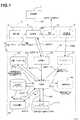
図1を参照すると、本出願の実施形態に係る微小電気機械素子(MEMS)追跡可能部材の全体を、手術用ツールまたは身体要素(例えば骨)などの追跡要素10に固定されている状態で12に示す。 Referring to FIG. 1, an entire microelectromechanical element (MEMS) trackable member according to an embodiment of the present application is secured 12 to a
MEMS追跡可能部材12は、追跡システム(CAS追跡システムなど)に用いられ、追跡回路20(例えば、慣性センサユニット)と、送信機21(または、無線送信機、送受信機など同種の通信回路)と、任意の確認インジケータ22と、受動追跡可能副部材23とを備える。別段に記載がない限り、以降、送信機への言及には送受信機を含むものとする。 The MEMS
本開示の実施形態において、追跡回路は、6自由度(以下、DOFという)の集積回路であってもよい。追跡回路20は、追跡可能部材12の位置および方向に関するデータを出力する。 In the embodiment of the present disclosure, the tracking circuit may be an integrated circuit having six degrees of freedom (hereinafter referred to as DOF). The
追跡回路20としての使用に適した装置の例には、他の候補の中でも、容量型加速度センサ(CAPAS)、電解傾斜センサおよび3軸線センサ(TAS)がある。CAPASは、追跡要素10に固定されることによって、その加速度(例えば重力)の2軸線測定を行う。一実施形態において、CAPASの物理的大きさは、縦7.4、横7.0、高さ3.5mmである。 Examples of devices suitable for use as the
加速度センサベースの追跡回路20が3DOFの方向を提供するように、加速度センサベースの追跡回路20を較正する方法およびシステムを以下で説明する。一部の用途においては、3DOFの方向追跡で十分である。3DOFを上回る方向を提供するように追跡回路20を構成する必要はなく、DOF位置を提供する受動追跡可能部材に追跡回路20を接続する必要もない。 A method and system for calibrating accelerometer-based
CAPASの作動状態において、加速度の変動はCAPASの方向の修正を反映している。CAPASの出力は、2軸線(またはCAPASが較正される場合は3軸線)の相対角度値である。従って、較正された追跡回路20、または前述の構成で2個のCAPASを有する追跡回路20は、追跡回路20の実時間方向データを提供し、それにより追跡要素10の実時間方向データを提供する。 In the operational state of CAPAS, the acceleration variation reflects the correction of the CAPAS direction. The output of CAPAS is a relative angle value of two axes (or three axes if CAPAS is calibrated). Accordingly, the calibrated
別の実施形態において、追跡可能副部材23は、追跡可能部材12に関する位置データを提供するために、追跡可能部材12の一部であってもよい。従って、追跡回路20が出力する方向データは、追跡可能副部材23の追跡から得られる位置データと組み合わされて、追跡要素の空間位置および方向を提供する。追跡可能副部材23には、超音波、光学素子およびRFエミッタなどの公知の技術を使用できる。一実施形態では、逆反射素子(例えば、球体、幾何パッチ)を使用する。単一の追跡可能副部材23(例えば、1球体)が、位置データを取得する追跡可能副部材23として必要であることが指摘される。但し、位置データの精度を高めるために、または光学追跡の場合には追跡可能部材23の視認性を高めるために、2個以上の追跡可能副部材23を使用することができる。従って、単一の追跡可能副部材23を有する追跡回路20としてCAPASを使用することによって、追跡可能部材12は、小型装置の6DOFの位置および方向を提供する。 In another embodiment, the trackable
別の実施形態において、3軸線加速度センサが用いられ、追跡可能副部材23の位置データを提供する。経時的な直線加速度を積分することにより、既知の初期位置からの変位量を算出して、副部材23の現在位置を提供できる。 In another embodiment, a triaxial acceleration sensor is used to provide position data for the trackable
追跡回路20のCAPASの代替として、TASが位置および方向データを提供する。TASは、集積回路に埋み込まれた3個のジャイロスコープおよび3個の加速度センサから構成される。一例として、利用可能なTASの物理的大きさは、縦23、横32、高さ5mmである。従って、これらTASの1つを使用することによって、一対のCAPASと追跡可能副部材23との組合せの場合と同様に位置および方向データが提供されるが、このTASは後者の組合せよりも大型である。 As an alternative to the CAPAS of the
送信機21は、追跡回路20に接続されて、追跡回路20の追跡データをCASシステムの処理システムに送信する。データの送信は、無線または有線接続によって行われてもよい。RFなど送信機21で使用される技術は、手術環境で作動するように選択されてもよい。一例として、Bluetooth(商標)、Zigbee(商標)またはWi-Fi送信機がその普及率に因って考慮され、追跡可能部材12の手術器具への統合を可能にする。追跡可能部材12は、単一の使い捨てユニットとして製造でき、場合によっては移植用計器(例えば、TKR用の使い捨て自己追跡切除ガイド)に統合できる。代替的な実施形態として、複数のセンサは、それらの間で必要な情報を通信するように構成可能である。 The
追跡可能部材12について考えられる別の特徴には、操作者または外科医にデータを提供する確認インジケータ22がある。例えば、手術用ツールの適当な位置/方向に関する指示がツール上に直接提供されることで、ツールを扱う外科医/操作者の手順を容易にしてもよい。確認インジケータ22は、CASシステムから受信した信号もしくは命令に対応する、オンオフ式のLED(例えば、赤色LEDおよび緑色LED)または別の適当な形態の小型電子ディスプレーを有する回路である。追跡可能装置12が確認インジケータ22を使用する実施形態において、送信機21は、CASシステムの処理システムから信号を受信する送受信機である。確認インジケータ22は、送受信機の回路に接続されて信号を受信し、それら信号を操作者/外科医に提供する可視信号に変換する。 Another possible feature for the
確認インジケータ22の別の実施形態は、追跡可能部材12が固定された器具の位置および方向に従ってオンになる一連のLEDまたは別の適当な形態の小型電子ディスプレーを包含する。このことは、外科医/操作者が様々な手術器具を扱っている時に、それらの整列/位置情報の通信を可能にするので、外科医は、当該情報をコンピュータスクリーンで見る必要がなくなる。 Another embodiment of the
追跡要素10として使用される手術用ツールには、登録ポインタ、切除ブロック、ドリル、やすり、ライティングスティックなどがある。 Surgical tools used as the tracking
追跡要素10が手術器具である場合に、追跡可能部材12を有する追跡要素10を較正するためには、器具の先端を基準点(較正マーカー)に突合せて、CASシステムが器具の方向を追跡できるようにする。他種の較正も追跡可能部材12で使用できる。例えば、図5を参照して、追跡要素10の方向を較正する方法を以下に記述する。 If the
さらに図1を参照すると、追跡可能部材12を組み込む追跡システムの全体が100で示され、1個以上の追跡可能部材12と共に使用される。追跡システムは、コンピュータ支援手術システム(CASシステム)であってもよく、プロセッサを有するコンピュータを典型的に備える処理ユニット101を有する。処理ユニット101には受信機102が設けられ、追跡可能部材12からの位置/方向データ信号を受信する。追跡可能部材12が確認インジケータ22を有する実施形態において、受信機201は、確認信号を追跡可能部材12に送信する送受信機である。 Still referring to FIG. 1, the entire tracking system incorporating the
制御部104は、受信機102に接続されている。従って、制御部104は、受信機102から信号データを受信する。 The
位置/方向計算部105は、受信/送受信機102から受信した信号データを追跡可能部材12用の位置/方向データに変換するよう用いられる。具体的に、追跡回路20がCAPASまたは較正CAPASの組合せである場合、信号データは追跡可能部材12の方向に変換される。追跡回路20がTASである場合、信号データは追跡可能部材12の位置および方向に変換される。 The position /
所定のCAS応用例の較正データ、および登録ポインタを用いて定義した骨モデルなどの他の術中データ、物体の軸線および座標系を格納する、幾何学的データベース106が設けられる。従って、位置データがその用途に必要である場合、較正データは、追跡要素10と追跡可能部材12との関係性となる。追跡可能副部材23を用いる実施形態において、較正データは、追跡可能副部材23を追跡要素10と関連付ける幾何学的データを備える。 A
従って、位置データを必要とする用途において、制御部104は、位置/方向計算部105から位置/方向データを受信し、データベース106が提供する関係データを用いることにより、追跡要素10の位置/方向を計算する。このようにして、制御部104は、位置/方向データをユーザインターフェース110に対して出力する。 Thus, in applications that require position data, the
追跡可能副部材23を一対のCAPASまたは較正CAPASと組み合わせて使用する実施形態において、処理ユニット101は、追跡可能部材12の追跡可能副部材23を追跡するために、センサユニット107(例えば、光学センサ装置)を任意で有する。通常、センサユニット102は、一対のセンサ(例えば、ナビトラック(商標))を包含する。 In embodiments where the
制御部104に関連して、位置計算部108を設けてもよい。位置計算部108は、センサユニット107による追跡から得られる追跡データを制御部104から受信する。データベース106が提供する幾何学的データにより、位置計算部108は追跡要素10の位置を計算する。 In relation to the
追跡要素10の位置が制御部104に送られ、追跡要素10の方向と組み合わされることによって、制御部104は追跡要素10の位置および方向を作成する。 The position of the
追跡システム10に、較正計算部109を設けてもよい。較正計算部109は、図3および図4に示すように、一対の2DOF方向追跡可能部材12(例えばCAPAS)と共に用いられ、第3DOFの方向が既知かつ追跡可能であるように、複数の追跡可能部材12の1つを較正する。 A
この情報がユーザインターフェース110に送られることで、システム100のユーザは、コンピュータ支援手術で公知の様々な形態(例えば、視覚表示、角度や距離などの数値)で追跡要素の位置および方向に関する情報を取得する。データベース106が制御部104の一部であったほうがよいことを指摘しておく。 This information is sent to the
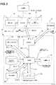
図2を参照すると、追跡可能部材の一実施形態が12’で示され、ここで自己閉鎖型処理ユニットは、追跡要素10に接続される。追跡可能部材12’は、追跡可能部材12に関して上述した追跡回路20、送受信機21および確認インジケータ22を有し、さらに制御部104、位置/方向計算部105、幾何学的データベース106、較正計算部109およびユーザインターフェース110も有し、これら全てを追跡要素10に直接固定される小型の自己閉鎖ケーシング内に有する。従って、送受信機21は、外科手術中に併用される他の追跡可能部材12’と情報を共有するために使用される。 With reference to FIG. 2, one embodiment of a trackable member is shown at 12 ′, where the self-closing processing unit is connected to the
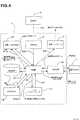
図3および図4の実施形態において、少なくとも2個の追跡可能部材12/12’が組み合わされて使用され、第1の追跡可能部材12’は、骨または他の体部位に固定される一方で、第2の追跡可能部材12/12’は、較正用にツール/器具または骨に装着される。従って、その追跡可能部材12’の追跡回路20が如何なる骨の変位も入手し、この情報はツール/器具上の追跡可能部材12’に送信される。追跡データが複数の追跡可能部材12’間で共有されることで、ユーザインターフェース110に提供される情報は、骨とツール/器具との間の相対移動を表す。 In the embodiment of FIGS. 3 and 4, at least two
場合によっては、骨と器具との間の方向(例えば軸線)だけが必要とされる。このような場合、追跡可能部材12’の追跡回路21は、CAPASを活用する。 In some cases, only the direction between the bone and the instrument (eg, the axis) is required. In such a case, the
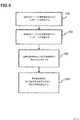
図5を参照すると、2DOFの方向に関する方向データを提供する、加速度計を有する追跡可能部材12/12’を較正する方法が提供され、これにより追跡可能部材12/12’の3(第3)DOFが提供される。 Referring to FIG. 5, a method is provided for calibrating a
図3〜図5に示すように、この方法は、加速度計を有する2個の追跡可能部材12/12’を設けることと、両方の追跡可能部材12/12’を物体10に装着することとを含む。複数の追跡可能部材12/12’の一方は基準追跡部材であり、他方は較正追跡部材である。従って、両方の追跡可能部材12/12’が、物体に関する2DOFの方向データを作成する。 As shown in FIGS. 3-5, the method includes providing two
150および154によると、両方の追跡可能部材12/12’からの方向データを追跡システム100の処理ユニットが受信する。操作者は次いで、物体が追跡可能部材12/12’の1DOF周りを移動するように、物体の運動を実行する。例えば、基準追跡部材12/12’の動きが手動で制限されることで、2DOFの方向が変わらぬ一方で、2DOFの他方の方向および較正追跡部材12/12’により追跡される2DOFの方向が変動する。 According to 150 and 154, the processing unit of the
158によると、追跡システム100の処理ユニットが、基準追跡部材12/12’および較正追跡部材12/12’の角変化率を決定する一方で、物体10は、上述のように、基準追跡部材の2自由度のうち一方の軸線を中心に回転する。 158, while the processing unit of the
これら角変化によって、追跡システム100の処理ユニットは、基準追跡部材12/12’の3(第3)DOFを決定できる。従って、162において、追跡システム100の処理ユニットは、決定した角変化率を使用することにより、基準追跡部材12/12’を基準に物体の方向を較正し、基準追跡部材12/12’の3(第3)自由度の方向を決定する。この較正手順により、基準追跡部材12/12’が提供する追跡データを通して、3自由度の方向で物体10を追跡できる。 These angular changes allow the processing unit of the
当該方法は、重力ベクトルおよび基準追跡部材12/12’の軸線の1つと整合する局所座標系を決定することと、基準追跡部材12/12’の3(第3)自由度を制限することとを包含する。基準追跡部材12/12’および較正追跡部材12/12’の方向は、上述の制限された回転の前後に、この局所座標系で表される。これにより、制限された回転の前後に、局所座標系における較正追跡部材12/12’の第3自由度に対応する2個の未知数を有する、完全に決定された方程式系が提供される。この方程式系を解くことにより、基準追跡部材12/12’に対する較正追跡部材12/12’の完全な3自由度が提供される。 The method includes determining a local coordinate system that is aligned with the gravity vector and one of the axes of the
図5の方法について、基準追跡部材12/12’および較正追跡部材12/12’が2DOFの方向の如何なる軸線とも整列しないことが好ましい。さらに、物体の移動がより大きな角変化率の値をもたらすので、158では、物体に対して振幅の大きな移動を行うことが好ましい。大きな角変化率により、3(第3)DOFの較正においてさらなる精度が得られる。 For the method of FIG. 5, it is preferred that the
基準追跡部材12/12’の回転軸線に関連するDOFの角変化率がないことが好ましいが、僅かな誤差が許容されてもよい。較正に関するデータの収集中に、処理ユニット101は、回転軸線の方向の角変化が最大閾値を超える際に、較正用の追跡データを受信しないようにプログラムされてもよい。 Although there is preferably no DOF angular rate of change associated with the axis of rotation of the
Claims (17)
Translated fromJapanese方向ベースのデータを少なくとも作成する第1慣性センサユニットを有する、第1追跡可能部材と、
方向ベースのデータを少なくとも作成する第2慣性センサユニットを有する、第2追跡可能部材であって、前記複数の追跡可能部材の一方は器具に接続され、前記複数の追跡可能部材の他方は骨に接続される第2追跡可能部材と、
前記複数の追跡可能部材から前記方向ベースのデータを受信する処理ユニットであって、前記処理ユニットは、前記両方の追跡可能部材の前記方向ベースのデータから、前記第1追跡可能部材に対する第2追跡可能部材の方向を計算する方向計算部を有し、これにより前記骨に対する前記器具の方向を計算する処理ユニットと、
を備えるコンピュータ支援手術システム。A computer assisted surgical system for tracking instruments and bone during surgery,
A first trackable member having a first inertial sensor unit that generates at least direction-based data;
A second trackable member having a second inertial sensor unit that generates at least direction-based data, wherein one of the plurality of trackable members is connected to an instrument and the other of the plurality of trackable members is to a bone A second traceable member connected;
A processing unit that receives the direction-based data from the plurality of trackable members, the processing unit from a second tracking for the first trackable member from the direction-based data of the both trackable members. A processing unit for calculating a direction of the possible member, thereby calculating a direction of the instrument relative to the bone;
A computer-assisted surgery system comprising:
前記第2慣性センサユニットは、前記骨に取り付けられ、2自由度の方向に関する方向データを作成する、加速度計ベースのユニットであり、
前記方向計算部は、前記骨が前記第1慣性センサユニットの2自由度のうち一方の軸線回りを回転している間に、第1慣性センサユニットおよび前記第2慣性センサユニットの角変化率を決定し、
前記処理ユニットは、前記決定した角変化率を用いることにより、前記第1慣性センサユニットを基準に前記骨の方向を較正する較正計算部をさらに備えて、前記第1慣性センサユニットの第3自由度の方向を決定し、これにより前記骨は3自由度の方向で追跡可能となる請求項1に記載のコンピュータ支援手術システム。The first inertial sensor unit is an accelerometer-based unit that is attached to the bone and creates direction data relating to a direction of two degrees of freedom;
The second inertial sensor unit is an accelerometer-based unit that is attached to the bone and creates directional data relating to a direction of two degrees of freedom;
The direction calculation unit calculates angular change rates of the first inertial sensor unit and the second inertial sensor unit while the bone rotates around one of the two degrees of freedom of the first inertial sensor unit. Decide
The processing unit further includes a calibration calculation unit that calibrates the direction of the bone with respect to the first inertial sensor unit by using the determined angular change rate, and a third free sensor of the first inertial sensor unit. The computer-aided surgical system of claim 1, wherein a direction of degrees is determined so that the bone can be tracked in directions of three degrees of freedom.
前記物体に取り付けられた加速度計ベースの基準追跡部材から、2自由度の方向に関する方向データを受信することと、
前記物体に取り付けられた加速度計ベースの較正追跡部材から、2自由度の方向に関する方向データを受信することと、
前記物体が前記基準追跡部材の前記2自由度の方向のうち一方の軸線回りを回転している間に、前記基準追跡部材および前記較正追跡部材の角変化率を決定することと、
前記決定した角変化率を用いることにより、前記基準追跡部材を基準に前記物体の方向を較正し、前記基準追跡部材の第3自由度の方向を決定することと、
を含み、これにより、前記物体は3自由度の方向で追跡可能となる方法。A method of tracking the direction of an object with 3 degrees of freedom,
Receiving direction data for a direction of two degrees of freedom from an accelerometer-based reference tracking member attached to the object;
Receiving direction data for a direction of two degrees of freedom from an accelerometer-based calibration tracking member attached to the object;
Determining an angular rate of change of the reference tracking member and the calibration tracking member while the object is rotating about one of the two degrees of freedom directions of the reference tracking member;
Calibrating the direction of the object with reference to the reference tracking member by using the determined angular rate of change, and determining the direction of the third degree of freedom of the reference tracking member;
Whereby the object can be tracked in a direction of three degrees of freedom.
前記物体に取り付けられる加速度計ベースの基準追跡部材であって、2自由度の方向に関する方向データを作成する基準追跡部材と、
前記物体に取り付けられる加速度計ベースの較正追跡部材であって、2自由度の方向に関する方向データを作成する較正追跡部材と、
前記基準追跡部材および前記較正追跡部材から前記方向データを受信する処理ユニットであって、前記物体が前記基準追跡部材の前記2自由度のうち一方のみの軸線回りを回転している間に、前記基準追跡部材および前記較正追跡部材の角変化率を決定する方向計算部と、前記決定した角変化率を使用することにより、前記基準追跡部材を基準に前記物体の方向を較正し、前記基準追跡部材の第3自由度の方向を決定する、較正計算部とを備え、これにより、前記物体は3自由度の方向で追跡可能となる処理ユニットと、
を備えるシステム。A system for tracking the direction of three degrees of freedom of an object,
An accelerometer-based reference tracking member attached to the object, the reference tracking member creating directional data relating to a direction of two degrees of freedom;
An accelerometer-based calibration tracking member attached to the object, the calibration tracking member creating directional data for directions of two degrees of freedom;
A processing unit for receiving the direction data from the reference tracking member and the calibration tracking member, wherein the object rotates about only one of the two degrees of freedom of the reference tracking member; A direction calculation unit for determining an angular change rate of the reference tracking member and the calibration tracking member, and using the determined angular change rate, the direction of the object is calibrated with reference to the reference tracking member, and the reference tracking is performed. A processing unit for determining the direction of the third degree of freedom of the member, whereby the object can be tracked in the direction of three degrees of freedom;
A system comprising:
Applications Claiming Priority (5)
| Application Number | Priority Date | Filing Date | Title |
|---|---|---|---|
| US3918408P | 2008-03-25 | 2008-03-25 | |
| US61/039,184 | 2008-03-25 | ||
| US10017308P | 2008-09-25 | 2008-09-25 | |
| US61/100,173 | 2008-09-25 | ||
| PCT/CA2009/000405WO2009117832A1 (en) | 2008-03-25 | 2009-03-25 | Tracking system and method |
Related Child Applications (1)
| Application Number | Title | Priority Date | Filing Date |
|---|---|---|---|
| JP2014174515ADivisionJP6114241B2 (en) | 2008-03-25 | 2014-08-28 | Tracking device and tracking method |
Publications (2)
| Publication Number | Publication Date |
|---|---|
| JP2011517971Atrue JP2011517971A (en) | 2011-06-23 |
| JP2011517971A5 JP2011517971A5 (en) | 2012-04-05 |
Family
ID=47558993
Family Applications (1)
| Application Number | Title | Priority Date | Filing Date |
|---|---|---|---|
| JP2011501074APendingJP2011517971A (en) | 2008-03-25 | 2009-03-25 | Tracking device and tracking method |
Country Status (7)
| Country | Link |
|---|---|
| US (1) | US9144470B2 (en) |
| EP (1) | EP2257771A4 (en) |
| JP (1) | JP2011517971A (en) |
| CN (1) | CN101978243B (en) |
| AU (1) | AU2009227956B2 (en) |
| CA (1) | CA2715898C (en) |
| WO (1) | WO2009117832A1 (en) |
Cited By (5)
| Publication number | Priority date | Publication date | Assignee | Title |
|---|---|---|---|---|
| JP2014513572A (en)* | 2011-02-25 | 2014-06-05 | オーソソフト インコーポレイティド | Bone and tool tracking by MEMS in computer-assisted surgery |
| WO2016024797A1 (en)* | 2014-08-13 | 2016-02-18 | 주식회사 고영테크놀러지 | Tracking system and tracking method using same |
| JP2017080484A (en)* | 2011-02-08 | 2017-05-18 | ザ ジェネラル ホスピタル コーポレイション | Patient positioning system and method |
| JP2019088840A (en)* | 2013-01-16 | 2019-06-13 | ストライカー・コーポレイション | Navigation system and method for indicating and reducing line of sight errors |
| JP2021098032A (en)* | 2013-12-09 | 2021-07-01 | ラシュワン マフホウズ,モハメド | Bone reconstruction and orthopedic implants |
Families Citing this family (51)
| Publication number | Priority date | Publication date | Assignee | Title |
|---|---|---|---|---|
| US7559931B2 (en) | 2003-06-09 | 2009-07-14 | OrthAlign, Inc. | Surgical orientation system and method |
| WO2004112610A2 (en) | 2003-06-09 | 2004-12-29 | Vitruvian Orthopaedics, Llc | Surgical orientation device and method |
| US20090001969A1 (en)* | 2007-06-29 | 2009-01-01 | General Electric Company | System and method for electromagnetic navigation of a magnetic field generating probe |
| US11224443B2 (en) | 2008-03-25 | 2022-01-18 | Orthosoft Ulc | Method and system for planning/guiding alterations to a bone |
| JP5651579B2 (en)* | 2008-03-25 | 2015-01-14 | オーソソフト インコーポレイテッド | Method and system for planning / inducing changes to bone |
| AU2009273863B2 (en) | 2008-07-24 | 2014-12-18 | OrthAlign, Inc. | Systems and methods for joint replacement |
| AU2009291743B2 (en) | 2008-09-10 | 2015-02-05 | Orthalign, Inc | Hip surgery systems and methods |
| US8444564B2 (en)* | 2009-02-02 | 2013-05-21 | Jointvue, Llc | Noninvasive diagnostic system |
| US8118815B2 (en) | 2009-07-24 | 2012-02-21 | OrthAlign, Inc. | Systems and methods for joint replacement |
| US10869771B2 (en) | 2009-07-24 | 2020-12-22 | OrthAlign, Inc. | Systems and methods for joint replacement |
| US9115998B2 (en) | 2010-01-19 | 2015-08-25 | Orthosoft Inc. | Tracking system and method |
| WO2011089606A1 (en)* | 2010-01-20 | 2011-07-28 | Creative Team Instruments Ltd. | Orientation dector for use with a hand-held surgical or dental tool |
| AU2011341678B2 (en) | 2010-01-21 | 2014-12-11 | OrthAlign, Inc. | Systems and methods for joint replacement |
| US8652148B2 (en) | 2010-02-25 | 2014-02-18 | Zimmer, Inc. | Tracked cartilage repair system |
| US9901405B2 (en) | 2010-03-02 | 2018-02-27 | Orthosoft Inc. | MEMS-based method and system for tracking a femoral frame of reference |
| US9706948B2 (en) | 2010-05-06 | 2017-07-18 | Sachin Bhandari | Inertial sensor based surgical navigation system for knee replacement surgery |
| US9597156B2 (en)* | 2010-07-30 | 2017-03-21 | Orthosoft Inc. | Bone tracking with a gyroscope sensor in computer-assisted surgery |
| US10070869B2 (en)* | 2011-02-25 | 2018-09-11 | Orthosoft Inc. | Bone and tool tracking with MEMS in computer-assisted surgery |
| DE102011050240A1 (en) | 2011-05-10 | 2012-11-15 | Medizinische Hochschule Hannover | Apparatus and method for determining the relative position and orientation of objects |
| US9549742B2 (en) | 2012-05-18 | 2017-01-24 | OrthAlign, Inc. | Devices and methods for knee arthroplasty |
| AU2013296108B2 (en) | 2012-07-24 | 2017-08-31 | Orthosoft Ulc | Patient specific instrumentation with mems in surgery |
| US9649160B2 (en) | 2012-08-14 | 2017-05-16 | OrthAlign, Inc. | Hip replacement navigation system and method |
| US9993273B2 (en) | 2013-01-16 | 2018-06-12 | Mako Surgical Corp. | Bone plate and tracking device using a bone plate for attaching to a patient's anatomy |
| GB201304411D0 (en)* | 2013-03-12 | 2013-04-24 | Meredith Neil | Improvements in Surgical Instruments |
| US9585768B2 (en) | 2013-03-15 | 2017-03-07 | DePuy Synthes Products, Inc. | Acetabular cup prosthesis alignment system and method |
| FR3010628B1 (en) | 2013-09-18 | 2015-10-16 | Medicrea International | METHOD FOR REALIZING THE IDEAL CURVATURE OF A ROD OF A VERTEBRAL OSTEOSYNTHESIS EQUIPMENT FOR STRENGTHENING THE VERTEBRAL COLUMN OF A PATIENT |
| US9924950B2 (en) | 2013-09-25 | 2018-03-27 | Zimmer, Inc. | Patient specific instrumentation (PSI) for orthopedic surgery and systems and methods for using X-rays to produce same |
| FR3012030B1 (en) | 2013-10-18 | 2015-12-25 | Medicrea International | METHOD FOR REALIZING THE IDEAL CURVATURE OF A ROD OF A VERTEBRAL OSTEOSYNTHESIS EQUIPMENT FOR STRENGTHENING THE VERTEBRAL COLUMN OF A PATIENT |
| US10258256B2 (en) | 2014-12-09 | 2019-04-16 | TechMah Medical | Bone reconstruction and orthopedic implants |
| DE102014200326A1 (en) | 2014-01-10 | 2015-07-16 | Siemens Aktiengesellschaft | A method of supporting navigation of a medical instrument |
| US10363149B2 (en) | 2015-02-20 | 2019-07-30 | OrthAlign, Inc. | Hip replacement navigation system and method |
| FR3034004A1 (en)* | 2015-03-24 | 2016-09-30 | Ostesys | GUIDING SYSTEM FOR IMPLEMENTING OSTEOTOMY |
| CN104758066B (en)* | 2015-05-06 | 2017-05-10 | 中国科学院深圳先进技术研究院 | Equipment for surgical navigation and surgical robot |
| AU2016291149B2 (en) | 2015-07-08 | 2019-10-10 | Zimmer, Inc. | Sensor-based shoulder system and method |
| US10456211B2 (en) | 2015-11-04 | 2019-10-29 | Medicrea International | Methods and apparatus for spinal reconstructive surgery and measuring spinal length and intervertebral spacing, tension and rotation |
| US11064904B2 (en) | 2016-02-29 | 2021-07-20 | Extremity Development Company, Llc | Smart drill, jig, and method of orthopedic surgery |
| US10537395B2 (en) | 2016-05-26 | 2020-01-21 | MAKO Surgical Group | Navigation tracker with kinematic connector assembly |
| WO2018058247A1 (en) | 2016-09-29 | 2018-04-05 | Orthosoft Inc. | Computer-assisted surgery system and method for calculating a distance with inertial sensors |
| WO2018109556A1 (en) | 2016-12-12 | 2018-06-21 | Medicrea International | Systems and methods for patient-specific spinal implants |
| EP3595554A4 (en) | 2017-03-14 | 2021-01-06 | OrthAlign, Inc. | Hip replacement navigation systems and methods |
| CA3056495A1 (en) | 2017-03-14 | 2018-09-20 | OrthAlign, Inc. | Soft tissue measurement & balancing systems and methods |
| EP3612122B1 (en) | 2017-04-21 | 2023-12-20 | Medicrea International | A system for developing one or more patient-specific spinal implants |
| US10918422B2 (en) | 2017-12-01 | 2021-02-16 | Medicrea International | Method and apparatus for inhibiting proximal junctional failure |
| US12349982B2 (en) | 2019-02-21 | 2025-07-08 | Surgical Targeted Solutions Inc. | Instrument bourne optical time of flight kinematic position sensing system for precision targeting and methods of surgery |
| US11944385B2 (en) | 2019-04-02 | 2024-04-02 | Medicrea International | Systems and methods for medical image analysis |
| US11877801B2 (en) | 2019-04-02 | 2024-01-23 | Medicrea International | Systems, methods, and devices for developing patient-specific spinal implants, treatments, operations, and/or procedures |
| US11925417B2 (en) | 2019-04-02 | 2024-03-12 | Medicrea International | Systems, methods, and devices for developing patient-specific spinal implants, treatments, operations, and/or procedures |
| US12059804B2 (en) | 2019-05-22 | 2024-08-13 | Mako Surgical Corp. | Bidirectional kinematic mount |
| US11769251B2 (en) | 2019-12-26 | 2023-09-26 | Medicrea International | Systems and methods for medical image analysis |
| CN115701948A (en) | 2020-08-04 | 2023-02-14 | 史赛克公司 | System and method for visualizing a trajectory with a surgical instrument |
| US12318144B2 (en) | 2021-06-23 | 2025-06-03 | Medicrea International SA | Systems and methods for planning a patient-specific spinal correction |
Citations (3)
| Publication number | Priority date | Publication date | Assignee | Title |
|---|---|---|---|---|
| JPH05212056A (en)* | 1992-02-10 | 1993-08-24 | Olympus Optical Co Ltd | Device for adjusting microscope for operation |
| JP2002090650A (en)* | 2000-07-11 | 2002-03-27 | Asahi Optical Co Ltd | Anti-vibration microscope |
| WO2008044679A1 (en)* | 2006-10-10 | 2008-04-17 | Saga University | Surgery support system |
Family Cites Families (26)
| Publication number | Priority date | Publication date | Assignee | Title |
|---|---|---|---|---|
| US3868565A (en)* | 1973-07-30 | 1975-02-25 | Jack Kuipers | Object tracking and orientation determination means, system and process |
| US5645077A (en)* | 1994-06-16 | 1997-07-08 | Massachusetts Institute Of Technology | Inertial orientation tracker apparatus having automatic drift compensation for tracking human head and other similarly sized body |
| US5971976A (en)* | 1996-02-20 | 1999-10-26 | Computer Motion, Inc. | Motion minimization and compensation system for use in surgical procedures |
| US6122538A (en)* | 1997-01-16 | 2000-09-19 | Acuson Corporation | Motion--Monitoring method and system for medical devices |
| AU768975B2 (en)* | 1999-05-03 | 2004-01-15 | Ao Technology Ag | Position detector with auxiliary means for detecting the direction of the gravity vector |
| US7386339B2 (en)* | 1999-05-18 | 2008-06-10 | Mediguide Ltd. | Medical imaging and navigation system |
| AU2002230578A1 (en)* | 2000-10-30 | 2002-05-15 | Naval Postgraduate School | Method and apparatus for motion tracking of an articulated rigid body |
| US7065393B2 (en)* | 2002-07-11 | 2006-06-20 | Cedara Software Corp. | Apparatus, system and method of calibrating medical imaging systems |
| US20050113646A1 (en)* | 2003-11-24 | 2005-05-26 | Sotos John G. | Method and apparatus for evaluation of sleep disorders |
| US20040039396A1 (en)* | 2002-08-23 | 2004-02-26 | Orthosoft Inc. | Universal positioning block |
| US7736368B2 (en)* | 2002-08-23 | 2010-06-15 | Orthosoft Inc. | Surgical universal positioning block and tool guide |
| EP1615577A2 (en)* | 2003-02-04 | 2006-01-18 | Orthosoft, Inc. | Cas modular bone reference assembly and limb position measurement system |
| WO2004091419A2 (en)* | 2003-04-08 | 2004-10-28 | Wasielewski Ray C | Use of micro-and miniature position sensing devices for use in tka and tha |
| US7559931B2 (en)* | 2003-06-09 | 2009-07-14 | OrthAlign, Inc. | Surgical orientation system and method |
| JP4009617B2 (en) | 2004-05-26 | 2007-11-21 | オリンパス株式会社 | Position relation detection apparatus and position relation detection system |
| US7702379B2 (en)* | 2004-08-25 | 2010-04-20 | General Electric Company | System and method for hybrid tracking in surgical navigation |
| DE102004057933A1 (en)* | 2004-12-01 | 2006-06-08 | Fraunhofer-Gesellschaft zur Förderung der angewandten Forschung e.V. | A method and apparatus for navigating and positioning an object relative to a patient |
| WO2006088845A2 (en)* | 2005-02-15 | 2006-08-24 | Walleye Technologies, Inc. | Electromagnetic scanning imager |
| US8632461B2 (en)* | 2005-06-21 | 2014-01-21 | Koninklijke Philips N.V. | System, method and apparatus for navigated therapy and diagnosis |
| US20070032748A1 (en)* | 2005-07-28 | 2007-02-08 | 608442 Bc Ltd. | System for detecting and analyzing body motion |
| SE529403C2 (en)* | 2005-12-15 | 2007-07-31 | Sven-Ingvar Lundahl | Device for a pair of goggles |
| CN100493471C (en)* | 2006-01-26 | 2009-06-03 | 清华大学深圳研究生院 | Puncture navigation system in computer-aided percutaneous nephrolithotomy |
| US7594933B2 (en)* | 2006-08-08 | 2009-09-29 | Aesculap Ag | Method and apparatus for positioning a bone prosthesis using a localization system |
| US8915866B2 (en)* | 2008-01-18 | 2014-12-23 | Warsaw Orthopedic, Inc. | Implantable sensor and associated methods |
| BRPI0907765A8 (en)* | 2008-02-05 | 2016-04-26 | Bayer Materialscience Ag | SECURITY ELEMENT |
| IL203642A (en)* | 2010-02-01 | 2014-01-30 | Yesaiahu Redler | Apparatus and method for optimizinmg current use during control of multiple motors and a projectile device containing the same |
- 2009
- 2009-03-25CACA2715898Apatent/CA2715898C/ennot_activeExpired - Fee Related
- 2009-03-25WOPCT/CA2009/000405patent/WO2009117832A1/enactiveApplication Filing
- 2009-03-25AUAU2009227956Apatent/AU2009227956B2/ennot_activeCeased
- 2009-03-25EPEP09723657.4Apatent/EP2257771A4/ennot_activeCeased
- 2009-03-25CNCN2009801099990Apatent/CN101978243B/enactiveActive
- 2009-03-25JPJP2011501074Apatent/JP2011517971A/enactivePending
- 2009-03-25USUS12/410,854patent/US9144470B2/enactiveActive
Patent Citations (3)
| Publication number | Priority date | Publication date | Assignee | Title |
|---|---|---|---|---|
| JPH05212056A (en)* | 1992-02-10 | 1993-08-24 | Olympus Optical Co Ltd | Device for adjusting microscope for operation |
| JP2002090650A (en)* | 2000-07-11 | 2002-03-27 | Asahi Optical Co Ltd | Anti-vibration microscope |
| WO2008044679A1 (en)* | 2006-10-10 | 2008-04-17 | Saga University | Surgery support system |
Cited By (10)
| Publication number | Priority date | Publication date | Assignee | Title |
|---|---|---|---|---|
| JP2017080484A (en)* | 2011-02-08 | 2017-05-18 | ザ ジェネラル ホスピタル コーポレイション | Patient positioning system and method |
| JP2014513572A (en)* | 2011-02-25 | 2014-06-05 | オーソソフト インコーポレイティド | Bone and tool tracking by MEMS in computer-assisted surgery |
| JP2019088840A (en)* | 2013-01-16 | 2019-06-13 | ストライカー・コーポレイション | Navigation system and method for indicating and reducing line of sight errors |
| JP2021098032A (en)* | 2013-12-09 | 2021-07-01 | ラシュワン マフホウズ,モハメド | Bone reconstruction and orthopedic implants |
| JP7395525B2 (en) | 2013-12-09 | 2023-12-11 | ラシュワン マフホウズ,モハメド | Bone reconstruction and orthopedic implants |
| WO2016024797A1 (en)* | 2014-08-13 | 2016-02-18 | 주식회사 고영테크놀러지 | Tracking system and tracking method using same |
| KR20160020065A (en)* | 2014-08-13 | 2016-02-23 | 주식회사 고영테크놀러지 | Tracking system and tracking method using the tracking system |
| KR101645392B1 (en) | 2014-08-13 | 2016-08-02 | 주식회사 고영테크놀러지 | Tracking system and tracking method using the tracking system |
| US10799299B2 (en) | 2014-08-13 | 2020-10-13 | Koh Young Technology Inc. | Tracking system and tracking method using same |
| US11730547B2 (en) | 2014-08-13 | 2023-08-22 | Koh Young Technology Inc. | Tracking system and tracking method using same |
Also Published As
| Publication number | Publication date |
|---|---|
| CN101978243A (en) | 2011-02-16 |
| US20090247863A1 (en) | 2009-10-01 |
| CN101978243B (en) | 2013-04-24 |
| EP2257771A1 (en) | 2010-12-08 |
| AU2009227956A1 (en) | 2009-10-01 |
| CA2715898A1 (en) | 2009-10-01 |
| US9144470B2 (en) | 2015-09-29 |
| CA2715898C (en) | 2018-05-08 |
| EP2257771A4 (en) | 2014-03-12 |
| WO2009117832A1 (en) | 2009-10-01 |
| AU2009227956B2 (en) | 2014-04-10 |
Similar Documents
| Publication | Publication Date | Title |
|---|---|---|
| JP6114241B2 (en) | Tracking device and tracking method | |
| JP2011517971A (en) | Tracking device and tracking method | |
| US9115998B2 (en) | Tracking system and method | |
| CN111417352B (en) | Method and system for setting trajectory and target location for image guided surgery | |
| JP2011517971A5 (en) | ||
| US9706948B2 (en) | Inertial sensor based surgical navigation system for knee replacement surgery | |
| US7797849B2 (en) | Portable metrology device | |
| EP2720634B1 (en) | Device for determining the mechanical axis of a bone | |
| EP4218647A1 (en) | System for computer assisted surgery | |
| JP2002533721A (en) | Hybrid 3D probe tracked by multiple sensors | |
| EP3302268B1 (en) | Leg length and offset calculation in computer-assisted surgery using rangefinder | |
| AU2008329463A1 (en) | Optical tracking CAS system | |
| US20230111411A1 (en) | Navigational and/or robotic tracking methods and systems | |
| TWI663954B (en) | Installation angle sensing system and method for artificial hip joint replacement |
Legal Events
| Date | Code | Title | Description |
|---|---|---|---|
| A521 | Request for written amendment filed | Free format text:JAPANESE INTERMEDIATE CODE: A523 Effective date:20120216 | |
| A621 | Written request for application examination | Free format text:JAPANESE INTERMEDIATE CODE: A621 Effective date:20120216 | |
| RD04 | Notification of resignation of power of attorney | Free format text:JAPANESE INTERMEDIATE CODE: A7424 Effective date:20130306 | |
| A977 | Report on retrieval | Free format text:JAPANESE INTERMEDIATE CODE: A971007 Effective date:20130425 | |
| A131 | Notification of reasons for refusal | Free format text:JAPANESE INTERMEDIATE CODE: A131 Effective date:20130430 | |
| A601 | Written request for extension of time | Free format text:JAPANESE INTERMEDIATE CODE: A601 Effective date:20130729 | |
| A602 | Written permission of extension of time | Free format text:JAPANESE INTERMEDIATE CODE: A602 Effective date:20130805 | |
| A521 | Request for written amendment filed | Free format text:JAPANESE INTERMEDIATE CODE: A523 Effective date:20131030 | |
| A02 | Decision of refusal | Free format text:JAPANESE INTERMEDIATE CODE: A02 Effective date:20140428 |