JP2011517274A - Telecommunications cable entry device - Google Patents
Telecommunications cable entry deviceDownload PDFInfo
- Publication number
- JP2011517274A JP2011517274AJP2011504039AJP2011504039AJP2011517274AJP 2011517274 AJP2011517274 AJP 2011517274AJP 2011504039 AJP2011504039 AJP 2011504039AJP 2011504039 AJP2011504039 AJP 2011504039AJP 2011517274 AJP2011517274 AJP 2011517274A
- Authority
- JP
- Japan
- Prior art keywords
- cable
- housing
- telecommunications
- incoming line
- incoming
- Prior art date
- Legal status (The legal status is an assumption and is not a legal conclusion. Google has not performed a legal analysis and makes no representation as to the accuracy of the status listed.)
- Pending
Links
- 230000006835compressionEffects0.000claimsabstractdescription12
- 238000007906compressionMethods0.000claimsabstractdescription12
- 239000013307optical fiberSubstances0.000claimsdescription16
- 238000004891communicationMethods0.000claimsdescription12
- RYGMFSIKBFXOCR-UHFFFAOYSA-NCopperChemical compound[Cu]RYGMFSIKBFXOCR-UHFFFAOYSA-N0.000claimsdescription9
- 230000014759maintenance of locationEffects0.000claimsdescription6
- 229910052802copperInorganic materials0.000claimsdescription5
- 239000010949copperSubstances0.000claimsdescription5
- 239000000835fiberSubstances0.000description17
- 238000007789sealingMethods0.000description11
- 230000003287optical effectEffects0.000description8
- 230000002787reinforcementEffects0.000description7
- 230000000994depressogenic effectEffects0.000description6
- 210000003811fingerAnatomy0.000description6
- 238000004873anchoringMethods0.000description5
- 239000012141concentrateSubstances0.000description5
- 230000000116mitigating effectEffects0.000description5
- 230000007613environmental effectEffects0.000description4
- 230000001681protective effectEffects0.000description4
- 239000004760aramidSubstances0.000description3
- 238000012986modificationMethods0.000description3
- 230000004048modificationEffects0.000description3
- 229920003235aromatic polyamidePolymers0.000description2
- 239000011248coating agentSubstances0.000description2
- 238000000576coating methodMethods0.000description2
- 238000007796conventional methodMethods0.000description2
- 238000013461designMethods0.000description2
- 239000003365glass fiberSubstances0.000description2
- 238000001746injection mouldingMethods0.000description2
- 238000003780insertionMethods0.000description2
- 230000037431insertionEffects0.000description2
- 238000000034methodMethods0.000description2
- 239000004033plasticSubstances0.000description2
- 230000003014reinforcing effectEffects0.000description2
- 241000196324EmbryophytaSpecies0.000description1
- 241000238631HexapodaSpecies0.000description1
- 240000005428Pistacia lentiscusSpecies0.000description1
- 229920006231aramid fiberPolymers0.000description1
- 230000004323axial lengthEffects0.000description1
- 230000000295complement effectEffects0.000description1
- 239000004519greaseSubstances0.000description1
- 238000009434installationMethods0.000description1
- 239000002184metalSubstances0.000description1
- 229910052751metalInorganic materials0.000description1
- 238000003825pressingMethods0.000description1
- 210000003813thumbAnatomy0.000description1
- XLYOFNOQVPJJNP-UHFFFAOYSA-NwaterSubstancesOXLYOFNOQVPJJNP-UHFFFAOYSA-N0.000description1
Images


Classifications
- H—ELECTRICITY
- H01—ELECTRIC ELEMENTS
- H01R—ELECTRICALLY-CONDUCTIVE CONNECTIONS; STRUCTURAL ASSOCIATIONS OF A PLURALITY OF MUTUALLY-INSULATED ELECTRICAL CONNECTING ELEMENTS; COUPLING DEVICES; CURRENT COLLECTORS
- H01R13/00—Details of coupling devices of the kinds covered by groups H01R12/70 or H01R24/00 - H01R33/00
- H01R13/58—Means for relieving strain on wire connection, e.g. cord grip, for avoiding loosening of connections between wires and terminals within a coupling device terminating a cable
- H01R13/59—Threaded ferrule or bolt operating in a direction parallel to the cable or wire
- G—PHYSICS
- G02—OPTICS
- G02B—OPTICAL ELEMENTS, SYSTEMS OR APPARATUS
- G02B6/00—Light guides; Structural details of arrangements comprising light guides and other optical elements, e.g. couplings
- G02B6/44—Mechanical structures for providing tensile strength and external protection for fibres, e.g. optical transmission cables
- G02B6/4439—Auxiliary devices
- G02B6/4471—Terminating devices ; Cable clamps
- G02B6/4477—Terminating devices ; Cable clamps with means for strain-relieving to interior strengths element
- H—ELECTRICITY
- H01—ELECTRIC ELEMENTS
- H01R—ELECTRICALLY-CONDUCTIVE CONNECTIONS; STRUCTURAL ASSOCIATIONS OF A PLURALITY OF MUTUALLY-INSULATED ELECTRICAL CONNECTING ELEMENTS; COUPLING DEVICES; CURRENT COLLECTORS
- H01R13/00—Details of coupling devices of the kinds covered by groups H01R12/70 or H01R24/00 - H01R33/00
- H01R13/73—Means for mounting coupling parts to apparatus or structures, e.g. to a wall
- H01R13/74—Means for mounting coupling parts in openings of a panel
- H01R13/741—Means for mounting coupling parts in openings of a panel using snap fastening means
- H01R13/743—Means for mounting coupling parts in openings of a panel using snap fastening means integral with the housing
- H—ELECTRICITY
- H02—GENERATION; CONVERSION OR DISTRIBUTION OF ELECTRIC POWER
- H02G—INSTALLATION OF ELECTRIC CABLES OR LINES, OR OF COMBINED OPTICAL AND ELECTRIC CABLES OR LINES
- H02G3/00—Installations of electric cables or lines or protective tubing therefor in or on buildings, equivalent structures or vehicles
- H02G3/22—Installations of cables or lines through walls, floors or ceilings, e.g. into buildings
- G—PHYSICS
- G02—OPTICS
- G02B—OPTICAL ELEMENTS, SYSTEMS OR APPARATUS
- G02B6/00—Light guides; Structural details of arrangements comprising light guides and other optical elements, e.g. couplings
- G02B6/44—Mechanical structures for providing tensile strength and external protection for fibres, e.g. optical transmission cables
- G02B6/4439—Auxiliary devices
- G02B6/4471—Terminating devices ; Cable clamps
- G02B6/4478—Bending relief means
- H—ELECTRICITY
- H01—ELECTRIC ELEMENTS
- H01R—ELECTRICALLY-CONDUCTIVE CONNECTIONS; STRUCTURAL ASSOCIATIONS OF A PLURALITY OF MUTUALLY-INSULATED ELECTRICAL CONNECTING ELEMENTS; COUPLING DEVICES; CURRENT COLLECTORS
- H01R13/00—Details of coupling devices of the kinds covered by groups H01R12/70 or H01R24/00 - H01R33/00
- H01R13/56—Means for preventing chafing or fracture of flexible leads at outlet from coupling part
- H01R13/562—Bending-relieving
Landscapes
- Engineering & Computer Science (AREA)
- Architecture (AREA)
- Civil Engineering (AREA)
- Structural Engineering (AREA)
- Physics & Mathematics (AREA)
- Optics & Photonics (AREA)
- General Physics & Mathematics (AREA)
- Light Guides In General And Applications Therefor (AREA)
- Installation Of Indoor Wiring (AREA)
- Cable Accessories (AREA)
- Insertion, Bundling And Securing Of Wires For Electric Apparatuses (AREA)
- Telephone Set Structure (AREA)
- Details Of Connecting Devices For Male And Female Coupling (AREA)
Abstract
Translated fromJapaneseDescription
Translated fromJapanese本発明は、光ファイバー、銅線又は同軸ケーブルを含む電気通信ケーブルを電気通信エンクロージャー、例えば、端子密閉部、予めスタブされた端子、光ネットワーク端子、又は他の配線接続ボックスに挿入するための入線装置に関する。 The present invention relates to an incoming device for inserting a telecommunication cable including an optical fiber, a copper wire or a coaxial cable into a telecommunication enclosure, for example, a terminal seal, a pre-stubbed terminal, an optical network terminal, or other wiring connection box. About.
電気通信ケーブルは至る所に存在し、データを広範なネットワークにわたって配信するために使用されている。ますます大量のデータが伝送されるにつれて、光ファイバーケーブルの使用が電気通信ネットワークで急増しつつあるが、ケーブルの大半は電気導電性ケーブル(通常は銅)である。 Telecommunications cables are ubiquitous and are used to distribute data across a wide range of networks. As increasingly large amounts of data are transmitted, the use of fiber optic cables is rapidly increasing in telecommunications networks, but the majority of cables are electrically conductive cables (usually copper).
電気通信ケーブルが、データネットワークの隅から隅まで張り巡らされているので、その中の1つ以上の通信回線をスプライスして、これによりデータを通信ネットワークの他のケーブル又は「分岐」へ分配することが可能になるようにケーブルを定期的に開くことが必要である。電気通信ケーブルが開けられる各地点では、ケーブルの露出した内部を保護するために、電気通信エンクロージャーを設けることが必要である。ケーブル枝線は、ネットワークが個人宅、企業、オフィスなどに達するまで更に分配することができる。 As telecommunications cables are routed from corner to corner of a data network, one or more communication lines within it are spliced, thereby distributing data to other cables or “branches” of the communication network. It is necessary to open the cable regularly so that it is possible. At each point where a telecommunications cable can be opened, it is necessary to provide a telecommunications enclosure to protect the exposed interior of the cable. Cable branches can be further distributed until the network reaches private homes, businesses, offices, etc.
端子エンクロージャーは、典型的には最終的なサービスをエンドユーザに配信するためにエンドユーザの近くに設置される電気通信エンクロージャーの一種である。典型的なファイバー端子は、典型的には4人から12人のエンドユーザを有する少数の施設にサービスを引き込むように(サービス接続を提供するように)設計される。ファイバー端子からの最終サービス接続は、ドロップケーブルを使用して、エンドユーザの所に設置された光ネットワーク端子(ONT)になされる。例えば、光ファイバーネットワークにおいて、ONTは、エンドユーザの壁の上に取り付けられてもよい。ONTは、この光信号を通常の電気信号に変換して、音声(電話)、インターネット(データ)、及び映像信号をエンドユーザに提供する。 A terminal enclosure is a type of telecommunications enclosure that is typically installed near an end user to deliver the final service to the end user. A typical fiber terminal is designed to draw service (providing service connections) to a small number of facilities, typically having 4 to 12 end users. The final service connection from the fiber terminal is made to the optical network terminal (ONT) installed at the end user using a drop cable. For example, in an optical fiber network, the ONT may be mounted on the end user's wall. The ONT converts this optical signal into a normal electrical signal and provides voice (telephone), internet (data), and video signals to the end user.
多くの従来の電気通信エンクロージャーは、エンクロージャーにケーブルを導入するために、マスチック、又はゴムグロメットのどちらかを利用している。米国特許第6,487,344号及び米国特許公開第2009−0060421−A1号に記載されている従来の入線装置は、電気通信エンクロージャーの壁のポートに挿入することのできるものである。 Many conventional telecommunications enclosures utilize either mastics or rubber grommets to introduce cables into the enclosure. The conventional incoming devices described in US Pat. No. 6,487,344 and US Patent Publication No. 2009-0060421-A1 are those that can be inserted into a port on the wall of a telecommunications enclosure.
電気通信エンクロージャーに電気通信ケーブルを挿入するための入線装置が本書に記載される。入線装置は、ハウジング及び圧縮部材を含む。ハウジングは、第一末端部及び第二末端部を有し、ハウジングは、ハウジングの第二末端部で圧縮性部分、及びハウジングの第一末端部に隣接する固定領域を含む。固定領域は、電気通信エンクロージャーの密閉ポート内に入線装置を固定させるためにハウジングの反対側から突出している複数の変形可能なロッキング要素を含む。 A line-in device for inserting a telecommunications cable into a telecommunications enclosure is described herein. The incoming line device includes a housing and a compression member. The housing has a first end and a second end, the housing including a compressible portion at the second end of the housing and a securing region adjacent to the first end of the housing. The securing region includes a plurality of deformable locking elements that project from the opposite side of the housing to secure the incoming device within the sealed port of the telecommunications enclosure.
別の実施形態では、入線装置は、ハウジング、ケーブル固定装置及び締め付けナットを含む。ハウジングは、第一末端部及び第二末端部を有し、ハウジングは、ハウジングの第二末端部で圧縮性部分、及びハウジングの第一末端部に隣接する固定領域を含む。固定領域は、電気通信エンクロージャーの密閉ポート内に入線装置を固定させるためにハウジングの反対側から突出している複数の変形可能なロッキング要素を含む。ケーブル固定装置は、入線装置内に電気通信ケーブルを集中させるためにハウジングの圧縮部分を圧縮している。締め付けナットは、ケーブル保持装置の第二末端部に固定されている。 In another embodiment, the incoming line device includes a housing, a cable securing device and a clamping nut. The housing has a first end and a second end, the housing including a compressible portion at the second end of the housing and a securing region adjacent to the first end of the housing. The securing region includes a plurality of deformable locking elements that project from the opposite side of the housing to secure the incoming device within the sealed port of the telecommunications enclosure. The cable fixing device compresses the compression portion of the housing to concentrate the telecommunications cable within the incoming device. The clamping nut is fixed to the second end of the cable holding device.
別の実施形態では、入線装置は、電気通信エンクロージャー内に取り付けられてもよい。 In another embodiment, the incoming device may be mounted within a telecommunications enclosure.
本発明の上記の概要は、本発明の各図示の実施形態又は全ての実施を説明しようとするものではない。下記の図及び発明を実施するための形態によって、これらの実施形態を更に詳細に例示する。 The above summary of the present invention is not intended to describe each illustrated embodiment or every implementation of the present invention. These embodiments are illustrated in further detail by the following figures and modes for carrying out the invention.
本発明は、添付図面を参照して更に詳しく記述される。
本発明は種々の修正及び代替の形態に容易に応じるが、その細部は一例として図面にされており、また詳しく説明することにする。しかしながら、その意図は、記載された特定の実施形態に本発明を限定することにないことを理解するべきである。むしろ、付随する請求項によって定義される本発明の範囲内に入る修正、等価物、及び代替物すべてを網羅することを意図するものである。 While the invention is amenable to various modifications and alternative forms, specifics thereof have been shown by way of example in the drawings and will be described in detail. However, it should be understood that the intention is not to limit the invention to the particular embodiments described. Rather, the intention is to cover all modifications, equivalents, and alternatives falling within the scope of the invention as defined by the appended claims.
好ましい実施形態の以下の詳細な説明において、本発明を実施できる具体的な実施形態を説明する添付図面を参照する。説明する実施形態は、本発明によるすべての実施形態を網羅することを意図したものではない。他の実施形態を利用することもでき、また、構造的又は論理的な変更が、本発明の範囲から逸脱することなくなされ得ることが理解される。したがって、以下の詳細な説明は、限定的な意味で解釈されるべきではなく、また本発明の範囲は、添付の特許請求の範囲によって定義される。 In the following detailed description of the preferred embodiments, reference is made to the accompanying drawings that illustrate specific embodiments in which the invention can be practiced. The described embodiments are not intended to be exhaustive of all embodiments according to the invention. It will be understood that other embodiments may be utilized and structural or logical changes may be made without departing from the scope of the present invention. The following detailed description is, therefore, not to be taken in a limiting sense, and the scope of the present invention is defined by the appended claims.
本明細書の代表的な実施形態は、電気通信エンクロージャーに電気通信ケーブル(例えば、光ファイバーケーブル、銅線又は同軸ケーブル)を挿入するための入線装置を提供する。本入線装置の設計の具体的な利点には、単一ファイバーケーブル又は複数ファイバーケーブルのどちらかをデバイス内に集中させる、低コストで現場取り付け可能な入線装置が挙げられる。本発明の入線装置は、いくつかの従来の入線装置よりも少ない、簡単に現場で取り付けられる部品の数を有する。 Exemplary embodiments herein provide an entry device for inserting a telecommunications cable (eg, fiber optic cable, copper wire or coaxial cable) into a telecommunications enclosure. Particular advantages of this line-in device design include a low-cost field-installable line-in device that concentrates either a single fiber cable or multiple fiber cables in the device. The incoming line device of the present invention has fewer parts that can be easily installed in the field than some conventional incoming line devices.
代表的な入線装置は、ポートに電気通信ケーブルを固定するために、通信ケーブルに取り付けられ、電気通信エンクロージャー内のポートに挿入されてもよい。通信ネットワークアーキテクチャに依存して、電気通信エンクロージャーは、埋め込み式密閉部、空中の密閉部又は端子、屋外プラント若しくは壁取り付け通信ボックス内のファイバー配線ハブ若しくは光ネットワーク端子、構内用途のファイバー配線ハブ、壁取り付けパッチパネル、又は光ネットワーク端子であってよい。 A typical incoming device may be attached to a communication cable and inserted into a port in a telecommunications enclosure to secure the telecommunications cable to the port. Depending on the telecommunications network architecture, telecommunications enclosures can be embedded enclosures, airtight enclosures or terminals, fiber distribution hubs or optical network terminals in outdoor plants or wall-mounted communication boxes, fiber distribution hubs for indoor use, walls It may be an attached patch panel or an optical network terminal.
代表的な実施態様において、電気通信ケーブルは、光ファイバーケーブルである。光ファイバーケーブルは、典型的には、少なくとも1つの光ファイバー及び少なくとも1つの強度部材を囲む半剛性のシースを含む。光ファイバーは、1つ以上の緩いバッファー菅に同封されてもよく、又は1つ以上の光ファイバーリボンケーブルとして提供されてもよい。1〜12の光ファイバーを、遮水ジェル又はグリースによって囲まれた緩いバッファー菅内に存在させてもよい。リボンケーブルのそれぞれは、1〜24の光ファイバーを有することができる。各光ファイバーは、ガラス繊維を囲み保護する高分子コーティングを有する。代表的な光ファイバーケーブルの例には、レシリンク(ResiLink ADF)(商標)オールディエレクトリックフラットドロップケーブル(All-Dielectric Flad Drop Cable)(ピレリケーブルアンドシステムズ(Pirelli Cable and Systems)、ノースカロライナ州コロンビア(Columbia)から入手可能)、又はEZドロップケーブル(EZ Drop Cable)(ドラカ(Draka)、ノースカロライナ州クレアモント(Claremont))、及びミニDPフラットドロップケーブル(Mini DP Flat Cable)(OFS、ジョージア州ノースクロス(Northcross)から入手可能)がある。光ファイバーは、ガラス繊維を囲み保護する高分子コーティングを有する。強化部材は、半剛性の棒材、又は例えばアラミド繊維でできた解繊繊維の集まりのいずれかであってよい。 In an exemplary embodiment, the telecommunications cable is a fiber optic cable. A fiber optic cable typically includes a semi-rigid sheath surrounding at least one optical fiber and at least one strength member. The optical fiber may be enclosed in one or more loose buffer bottles or provided as one or more optical fiber ribbon cables. One to twelve optical fibers may be present in a loose buffer tub surrounded by a water shielding gel or grease. Each of the ribbon cables can have 1 to 24 optical fibers. Each optical fiber has a polymeric coating that surrounds and protects the glass fibers. Examples of typical fiber optic cables include the ResiLink ADF ™ All-Dielectric Flad Drop Cable (Pirelli Cable and Systems, Columbia, NC) Or EZ Drop Cable (Draka, Claremont, NC), and Mini DP Flat Cable (OFS, Northcross, GA) Available). The optical fiber has a polymeric coating that surrounds and protects the glass fiber. The reinforcing member may be either a semi-rigid bar or a collection of defibrated fibers made of aramid fibers, for example.
あるいは、電気通信ケーブルは、複数の銅線対又は銅製の同軸ケーブルを囲む半剛性シースを有する低カウントの銅線であってもよい。 Alternatively, the telecommunications cable may be a low count copper wire having a semi-rigid sheath surrounding a plurality of copper wire pairs or copper coaxial cable.
図1A〜1Cを参照すると、代表的な入線装置100は、第一末端部111及び第二末端部112を有するハウジング110、ハウジングの第二末端部内に受け入れられるように成形された内部シール部材140、並びにハウジングの第二末端部に取り付けられる圧縮部材を含む。圧縮部材は、ケーブル固定装置160、締め付けナット150、又は入線装置ハウジングの第二末端部にラジアル力を適用することのできるデバイスであってよい。図1A〜1Cに示されるように、圧縮部材は、ハウジング110の第二末端部111に取り付けられたケーブル固定装置160、及びケーブル固定装置160の第二末端部162に取り付けられた締め付けナットを含む。別の態様において、ケーブル固定装置は省略されてもよく、圧縮部材は、ハウジングの第二末端部に直接係合する締め付けナット150を含む。入線装置100は、従来の方法、例えば射出成形により、プラスチックで形成されることができる。 With reference to FIGS. 1A-1C, an
ハウジングは、一般的に円筒状の形状であり、内側通路113を含み、内側通路113は、ハウジングの第一末端部111から第二末端部112までハウジングの長さに沿って延びている。ハウジングは、内側通路の第一末端部111にある通路入り口114、及び単一ファイバードロップケーブル、複数ファイバーケーブル、銅の通信ケーブル、又は同軸ケーブルを含む、電気通信ケーブルの特定の種類に対応するように構成された通路出口116を内側通路113の第二末端部112に含む。 The housing is generally cylindrical in shape and includes an
入線装置が電気通信エンクロージャーのポートに十分に挿入されると、ハウジングの第一末端部は、電気通信エンクロージャー内にある。入線装置が電気通信エンクロージャーのポートに十分に挿入されると、ハウジングの第二末端部は、電気通信エンクロージャーのポート内に位置し得る。別の方法としては、管状体の第二末端部は、電気通信エンクロージャーのポートを完全に通って延びてもよい。 When the incoming device is fully inserted into the port of the telecommunications enclosure, the first end of the housing is in the telecommunications enclosure. When the incoming device is fully inserted into the port of the telecommunications enclosure, the second end of the housing may be located within the port of the telecommunications enclosure. Alternatively, the second end of the tubular body may extend completely through the port of the telecommunications enclosure.
ケーブル保持装置117は、ハウジング110の第一末端部111に隣接する位置にあってもよい。図1A及び2Aに示される代表的な一実施形態において、ケーブル保持装置117は、ハウジング110と一体化して形成されてもよい。ケーブル保持装置は、クリップ117a及びタイ部分117bを含んでもよい。クリップ117aは、例えば、締まりばめによって、ケーブル50をケーブル保持装置117内に保持することができる。場合によっては、ケーブルは、クリップ117aによって確実に保持されなくてもよく、その場合には、装置117内にケーブルを保持するために、ケーブルタイ又はストリング(図示せず)がタイ部分117b及びケーブルの周りで固定されてもよい。別の方法としては、光ファイバーケーブルをケーブル保持装置117に固定するために、いくつかの光ファイバーケーブル内にあるアラミド強化部材を、ケーブル部分117bの周りにアラミド強化部材の長さを巻き付け、それらを結んでまとめることによって、使用してもよい。図2Cに示される別の実施形態では、別のケーブル保持装置117’は、ケーブル保持装置117’の底部側の戻り止め又は正孔117a’にハウジング110’の延長部110a上に配置されたバンプ110bを位置決めすることにより適所にロックされるまで、ハウジングの第一末端部にケーブル保持装置上の舌状ピン117b’を挿入することなどによって、ハウジング110’の第一末端部111に固定できる別個の部品であってもよい。そのようなケーブル保持装置の代表的な実施形態は、米国特許第6,487,344号に説明されており、これは参照により、その全体が本明細書に組み込まれる。 The
ハウジング110は、ハウジングの第一末端部111に隣接する固定領域130を有してもよい。固定領域は、ハウジング110の側面から突出する1つ以上のロッキング要素132を含んでもよい。入線装置の代表的な実施形態では、ハウジングの反対側に配置された一対のロッキング要素が含まれ、押し下げたときに曲がることができる変形可能な片持梁構造を有してもよい。図2Bに示されるように、片持梁構造は、自由端137及び取り付け末端部136を含んでもよい。取り付け末端部136は、ハウジング110に結合され、片持梁構造132用のリビングヒンジとしての役割を果たす。図1C及び2Bに示される代表的な実施形態では、片持梁構造の自由端137は、内側へのラジアル力134を適用することによって押し下げられることができる。押し下げられるとき、片持梁構造の自由端137は、入線装置の内部の電気通信ケーブル50と片持梁構造132との間に形成されたギャップ135内に移動でき、その結果、片持梁構造は、その領域のハウジングの外側表面を越えて突出しない。この状態で、入線装置は、電気通信エンクロージャーの密閉取りつけポートから取り除くことができる。したがって、挿入後、ロッキング要素は、ハウジングの外側表面を越えて確実に突出して、入線装置を電気通信エンクロージャーの密閉取りつけポートにロックすることができる。更に、入線装置は、片持梁構造が十分に押し下げられたときに、密閉取りつけポートから取り除くことができる。 The
片持梁構造132は、図2A〜Cに示されるように、3つの側面上でハウジング110を有さない片持梁構造を切断することによって作られてもよい。別の方法として、片持梁構造132は、ハウジングが(例えば、射出成形によって)形成される場合に作られてもよい。別の実施形態では、ロッキング要素は、バネ仕掛けであってもよいし、又は入線装置のハウジングにロッキング要素を結合するヒンジピンを有してもよい。別の方法として、2つを超えるロッキング要素が使用されてもよい。好ましくは、ロッキング要素は、ハウジングの周囲に等しい間隔をあけて置かれてある。更に別の実施形態では、固定領域は、入線装置を電気通信エンクロージャーのポートに固定するために分岐状のロッキングデバイスが挿入され得る受け入れチャネルを含んでもよい。 The
溝146は、固定領域130とO−リングなどの外部密封部材145を受け入れるためのハウジング110の第二末端部112との間に位置してもよい。この外部密封部材は、入線装置が完全に中に設置されると、入線装置と電気通信エンクロージャーとの間に環境シールを提供することができる。 The
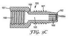
ハウジング110は、溝146とハウジング110の第二末端部112との間に位置する外部ねじ部118を有してもよい。外部ねじ部118は、圧縮部材(例えば、それぞれケーブル固定装置160又は締め付けナット150)の対応する内部ねじ部168、158(例えば、図3C及び4Bを参照)と協働して、入線装置に取り付けられた通信ケーブルの外側表面にハウジング110の圧縮性部分115をぴったり一致させる。 The
圧縮性部分115は、ハウジングの第二末端部112で形成される。外部のラジアル力が、締め付けナット150又はケーブル固定装置160の適用等によって圧縮性部分に及ぶ場合には、圧縮性部分115は小さいサイズ(直径)でもよい。入線装置が、電気通信ケーブル上に設置されると、圧縮性部分115は、入線装置100内に電気通信ケーブルを集中させる。圧縮性部分115は、通路出口116を囲む複数の相隔たった可撓性フィンガー115aを含んでもよい。フィンガー115aは、ケーブル固定装置160又は締め付けナット150のどちらかが、ハウジングの第二末端部に取り付けられた際に、互いに締め付けられ得る。埋められた又は他の地中の電気通信エンクロージャー設備で必要となり得る電気通信ケーブルの周りの入線装置の密封性を改善するために、任意の内側密封部材140が、ハウジング110の圧縮性部分115の内にある内側通路113に嵌め込まれてもよい。電気通信ケーブルが、入線装置100内に設置される場合、電気通信ケーブル50は、内側密封部材140を貫通する。ハウジングの折り畳み可能部分の上のケーブル固定装置又は締め付けナットの締め付けが、内側密封部材を圧縮する。構内設備のようなある種の用途においては、環境保護の度合いの要求はより少なく、内側密封部材140は、省かれてもよい。この場合、ハウジングの圧縮性部分は、それを通して挿入されたケーブルを直接しっかりと掴む。 The
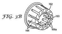
更に、図1Bに示されるように、ケーブル固定装置160は、ハウジング110の第二末端部112に取り付けられてもよい。図3A及び3Bは、本発明の代表的な態様によるケーブル固定装置160の代表的な実施形態を示している。ケーブル固定装置160は、第一末端部161から第二末端部162に延びる中央穴163を備えた細長い構造を有してもよい。ケーブル固定装置は、その第一末端部111に内側ねじ部168(図1C)、及び内側ねじ部168に隣接して内側傾斜壁部169を有することになる。内側ねじは、ハウジングの第二末端部上で外部ねじに対応することができる。内側傾斜壁部169は、ハウジング110の圧縮性部分115の上でラジアル力を及ぼして、入線装置内のケーブルを集中させるためにフィンガー115aをより緊密に押圧させる。折り畳み可能部分が、折り畳まれると、フィンガー115aに強く押圧することで、電気通信ケーブルに対して内側密封部材140(図1A)が圧縮されて、入線装置を貫通する電気通信ケーブルの周囲に環境シールを提供する。 Further, as shown in FIG. 1B, the
代表的な実施形態において、ケーブル固定装置160は、内側ねじ部168の位置に対応するケーブル固定装置の外側表面上に把持表面164を有してもよい。外側把持表面は、図3Aに示されるように、ツール又は手によるケーブル固定装置の把持を助けるように、六角形状の断面を有してもよい。把持表面領域は、円筒形の形状、矩形形状又は他の多角形の形状のような他の幾何学的形状を有してもよい。更に、把持表面は、ケーブル固定装置の把持を更に容易にするために非平滑化(例えば、畝状又は斜め交差の外見)されてもよい。 In the exemplary embodiment,
ケーブル固定装置160は、ケーブル固定装置の第二末端部162から延びている複数の相隔たる突起166を有してもよい。更に、外側ねじ部167は、把持表面164と突起166との間でケーブル固定装置の外側表面の上に配置されてもよい。 The
各突起166は、内側末端部(即ち、中央穴に向いている突起の側面)の近くに配置される返し166a及び/又は複数の歯(図示せず)を有してもよい。締め付けナット150がケーブル固定装置160の第二末端部162に固定される場合には、返し166aは、電気通信ケーブルのシースを貫通してもよい。締め付けナットは、相隔たる突起166上でラジアル力を及ぼして、それらを内側に押し、電気通信ケーブルのシース内に返し166aを押し込む。 Each
建物内の配線接続ボックスへのケーブル挿入のような構内用途では、入線装置は、環境密封要求性を低減させてもよい。これらの場合、ハウジングの圧縮性部分のフィンガーが、ケーブル固定装置160に関して上述したような返し又は歯を有する、短い軸長を有する入線装置を使用してもよい。したがって、このような用途に関して、上述のロッキング要素を備えた代表的な入線装置では、ケーブル固定装置及び内側密封部材を省略して、よりコンパクトな入線装置構造としてもよい。 For premises applications such as cable insertion into a wiring connection box in a building, the line entry device may reduce environmental sealing requirements. In these cases, a wire entry device having a short axial length may be used in which the fingers of the compressible portion of the housing have barbs or teeth as described above with respect to the
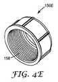
図4A〜4Eは、ケーブル締め付けナット150A〜150Eのいくつかの実施形態を説明している。締め付けナットの基本構造を、図4Dに関して説明する。図4Dに示されるケーブル締め付けナット150Dは、第一側面151と第二側面152との間で広がる内側チャンバー153を有する。内側チャンバー153は、ハウジング110(図2A)の第二末端部112及び/又はケーブル固定装置160(図3A)の第二末端部162を受け入れるために、第一末端部151に第一開口部154を有する。チャンバー153は、それを通る電気通信ケーブルの通路に対応するために、ケーブル締め付けナット150Dの第二末端部151に、より小さな第二開口部(図示せず)を有する。チャンバー153は、ケーブル締め付けナットがハウジング及び/又はケーブル固定装置に固定されるようにするために、ハウジングの第二末端部及び/又はケーブル固定装置の第二末端部上で外側ねじに対応することができる内側ねじ部158を有する。 4A-4E illustrate several embodiments of cable clamping nuts 150A-150E. The basic structure of the clamping nut is described with respect to FIG. 4D. The
代表的な実施形態において、ケーブル締め付けナット150Dは、内側ねじ部158の位置に対応するケーブル締め付けナットの外側表面上に把持表面157を有することができる。外側把持表面は、図4Dに示されるように、ツール又は手によるケーブル固定装置の把持を容易にするために六角形状断面であってもよい。把持表面領域は、円形断面(図4E)、矩形断面、又は他の多角形断面のような、他の幾何学的形状を有してもよい。更に、把持表面は、ケーブル固定装置の把持を更に容易にするために非平滑化(例えば、畝状又は斜め交差の外見)されてもよい。 In an exemplary embodiment, the
別の締め付けナット150Aが、図4Aに示されている。ケーブル締め付けナット150Aの基本構造は、締め付けナット150Dの基本構造に類似している。しかしながら、ケーブル締め付けナット150Aは、締め付け(claming)ナット150Aの第二側面162から延びる変形緩和ブラケット156を含む。変形緩和ブラケット156は、入線装置に設置されたときに、電気通信ケーブルと略一致し、それを受ける、凹形状の内表面156aを有してもよい。更に、変形緩和ブラケット156は、電気通信ケーブルを締め付けナット150Aに固定するために使用されるケーブルタイ(図示せず)に適合させるために、その外側表面に複数のノッチ156b又はチャネルを有してもよい。 Another clamping
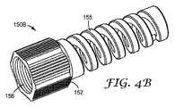
図4Bは、締め付けナットの第二末端部152上に配置された一体式曲げ制御ブート155を含むもう1つ別のケーブル締め付けナット150Bを示している。曲げ制御ブートは、電気通信ケーブルが、電気通信ケーブルで送られる信号の低下をもたらし得る、その最少曲げ半径を超えるのを防ぐ。ケーブル締め付けナットのこの実施形態の第二開口部は、図1Cに示される開口部154bである。 FIG. 4B shows another
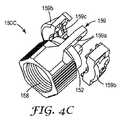
図4Cを参照すると、もう1つ別のケーブル締め付けナット150Cが示されている。ケーブル締め付けナット150Cは、電気通信ケーブルを確実に保持するために、ケーブル締め付けナット150Cの第二末端部152上に配置された保持クランプ159を含む。2つの長手方向側タブ159aは、締め付けナット150Cの第二末端部152から突出している。保持クランプ159の2つの半部分30及び31は、スクリューやリベットのような従来の機械的な留め金具(図示せず)によって、長手方向側タブに固定されることができる。2つのクランプの半部分の内面159cは、代表的な入線装置に設置される場合、凹形状であってよく、電気通信ケーブルを更に確実に掴むために電気通信ケーブルのシースに噛み合わせるための隆起又は返しを有してもよい。別の実施形態では、保持クランプの半部分の1つは、必要な部品の数を減らすために長手方向側タブと一体的に形成されてもよい。 Referring to FIG. 4C, another
図5は、第一末端部211及び第二末端部212を有するハウジング210の別の実施形態を示している。ハウジング210は、略円筒状であってよく、ハウジングの第一末端部211から第二末端部212までハウジングの長さに沿って延びている内側通路213を含む。ハウジングは、単一ファイバードロップケーブル及び複数ファイバーケーブルなどの電気通信ケーブルの特定の種類に対応するように構成され得る通路入り口を、内側通路213の第二末端部212に含む。 FIG. 5 illustrates another embodiment of a
ハウジング210は、ハウジングの第一末端部211に隣接する固定領域230を有してもよい。固定領域230は、ハウジング210の反対側から突出する一対のロッキング要素232を含んでもよい。代表的な入線装置において、ロッキング要素は、先述のように押し下げたときに曲がることができる変形可能な片持梁構造を有してもよい。 The
代表的なハウジング210は、ハウジングの第二末端部212に形成される圧縮性部分215を含む。圧縮性部分215は、保護スリーブ(図示せず)の適用によるように、外力がその上で半径方向に働く場合には、寸法を小さくしてもよい。入線装置が電気通信ケーブル上に設置される場合、圧縮性部分215は、電気通信ケーブルを入線装置の中に集中させる。圧縮性部分215は、通路入り口を囲む複数の相隔たる可撓性フィンガー215aを含んでもよい。この別の態様において、締め付けナット及びケーブル固定装置/締め付けナットの組み合わせは省かれてもよい。 The
ハウジング210の他の特徴には、ケーブル変形緩和アタッチメント表面260、配向制御部分270、外側密封部材を保持するための環状チャネル280(例えば、及びO−リング、図示せず)、及びケーブル保持装置217を挙げることができ、これらは全てハウジング210と一体的に形成される。 Other features of the
ハウジングの上に設置される場合、保護スリーブ(例えば、熱収縮チューブの一部分、図示せず)は、電気通信ケーブルの周りに防水性及び/又は防塵シールを固定しそれを提供するためにケーブル変形緩和アタッチメント表面260の上に嵌められてもよい。保護スリーブは、加熱されるにつれて圧縮性部分215を折り畳むラジアル力を及ぼす。更に、この保護スリーブは、電気通信エンクロージャーに設置されたときに、ケーブルの適切な曲げ半径を維持することによって、ケーブルに変形緩和を提供することができる。ケーブル変形緩和部材はまた、引き抜き力に逆らってケーブルを保持する。 When installed over a housing, a protective sleeve (eg, a portion of a heat shrink tube, not shown) can be used to secure and provide a waterproof and / or dust-proof seal around the telecommunications cable. It may be fitted over the
配向制御部分270は、入線装置200が、電気通信エンクロージャー300内の補完的ポート構造を有するポートに、既知の又は制御された配向で挿入される場合に利用され得る。 The
図6は、固定領域330がハウジング310の第一末端部311に隣接している、入線装置の別の固定領域構成を示している。固定領域330は、ハウジング310の第一末端部の反対側から突出する一対の弾力的なロッキング支柱332を含んでもよい。各ロッキング支柱332は、その外側遠位端の上に位置する脚333を有する。電気通信エンクロージャー内に設置されたとき、各支柱の上の脚は、電気通信エンクロージャー内の入線装置を保持するようにポートの入り口を越えて延びている。代表的な実施形態において、ロッキング支柱332は、入線装置の軸の長さに対して垂直の内向力334を適用することによって押し下げられることができる。押し下げれられたとき、各ロッキング支柱上の脚は、ハウジング310の外側表面を越えて突出する脚がないように位置決めされる。この状態で、入線装置は、電気通信エンクロージャーの密閉取りつけポートから取り除かれることができる。したがって、十分に挿入されたとき、ロッキング支柱332の末端部上の脚333は、入線装置を電気通信エンクロージャーの密閉取りつけポートにロックするためにハウジングの外側表面を越えて突出しているが、入線装置は、ロッキング支柱が十分に押し下げられる場合には、密閉取りつけポートから取り除かれることができる。 FIG. 6 shows another fixed region configuration of the line-fitting device where the fixed
図8は、代表的入線装置600のもう1つの別の実施形態を示している。入線装置600の特徴は、図1Bに示される入線装置100の特徴に類似している。しかしながら、入線装置600は、ケーブル固定装置160の第二末端部上に取り付けられ、締め付けナット150が定位置に固定されたときに定位置にロックされる、補助的な強化部材ホルダー620を含む。強化部材ホルダー620を、ドラカ(Draka)(ノースカロライナ州クレアモント(Claremont))から入手可能なEZドロップ(EZ-DROP)8の字形ドロップケーブルのような「8の字形」のドロップケーブルを伴う用途に使用してもよい。「8の字形」のドロップケーブル650は、光ファイバードロップケーブル652に取り付けられた外側強化部材又はメッセンジャー654を含む。代表的な強化部材ホルダー620は、環形ベース622に取り付けられた矩形のヨーク624を含む略鍵穴形を有してもよい。ヨーク624は、それを貫通する開口部628を有する。「8の字形」のドロップケーブルのメッセンジャーは、開口部628を通して挿入され、機械的なデバイス又は留め金具、例えば、親指スクリュー626、又は止めねじによって、定位置にロックされることができる。強化部材ホルダー620は、従来の方法によってプラスチック又は金属から形成されてよい。別の方法としては、強化部材ホルダー620は、締め付けナット150の第一末端部151上に一体的に形成されてよい。 FIG. 8 illustrates another alternative embodiment of the exemplary
電気通信ケーブルが開けられる各地点では、ケーブルの露出した内部を保護するために、電気通信エンクロージャーが設けられる。端子密閉部は、エンドユーザにサービスを分与するために通信ネットワークで使用される電気通信エンクロージャーの一種である。端子密閉部は、典型的に4人〜12人のエンドユーザを有する多くの家庭又は企業にサービス接続を提供するように設計される。 At each point where the telecommunications cable is opened, a telecommunications enclosure is provided to protect the exposed interior of the cable. Terminal seals are a type of telecommunications enclosure used in communication networks to distribute services to end users. Terminal seals are designed to provide service connections to many homes or businesses that typically have 4 to 12 end users.
本発明の1つの実施形態による代表的な電気通信エンクロージャー又は端子密閉部400を図7Aに示す。端子密閉部400は、ベース410及び取り外し可能でベースに固定可能なカバー又はハウジング(図示せず)を含む。ベース410は、入線装置100を受け入れるために少なくとも1つのポート420を含む。ベースは、特定の端子密閉部に必要とされる、1つ、2つ又はそれ以外の数のポート400を有し得る。図7Aに示される実施形態において、ポート420は、入線装置の形状によって可能になる六角形の最密充填構造内に配置される。この配列は、より小さい量の空隙内により多くのポートを適用することを可能にし、したがって、端子密閉部の容量が増大する可能性がある。六角形のケーブル固定装置及び/又は締め付けナットを有する入線装置に対応するようにポートが設計される場合、ポートの構造は蜂の巣に似たようなものにすることができる。カバーは、ベイル、クランプ又は他の機械的な締結方法によってベース410に固定されてもよい。係合すると、ベース及びカバーは、端子密閉部400の内部構成要素を、風雨、虫及び他の外部障害から保護する。 An exemplary telecommunications enclosure or
図7Bは、入線装置100が設置された場合に、入線装置100のロッキング要素132が端子エンクロージャーに係合している端子エンクロージャー400’の内部を示している。 FIG. 7B shows the interior of the
本明細書で説明される代表的な入線装置は、光ネットワーク端子(ONT)内に設置されてもよい。図7Cは、光ネットワーク端子500に挿入される入線装置100を示しており、顧客の家又は他の建物の場所の側面に位置し得るものである。ONTは、この光信号を従来の電気信号に変換して、ハイブリッド通信ネットワークにおいてエンドユーザに音声(電話)、インタネット(データ)、及びビデオ信号を提供する。 The typical incoming line device described herein may be installed in an optical network terminal (ONT). FIG. 7C shows the
上述した入線装置の実施形態は、簡単でユーザフレンドリーな設計を提供し、それによって、エンドユーザにFTTHネットワークの最後の支柱の取り付けを著しく容易にする。 The inlet device embodiment described above provides a simple and user-friendly design, thereby significantly facilitating the installation of the last post of the FTTH network to the end user.
入線装置の使用を、電気通信銅ケーブル又は同軸銅ケーブルを用いた用途、等価なプロセス、並びに本発明が応用され得る多数の構造に展開する様々な修正例が、本発明の対象とされる当業者には、本明細書を検討すれば容易に明らかとなろう。 Various modifications that extend the use of the wireline device to applications using telecommunications or coaxial copper cables, equivalent processes, and numerous structures to which the present invention can be applied, are covered by the present invention. It will be readily apparent to those skilled in the art after reviewing this specification.
Claims (12)
Translated fromJapanese第一末端部及び第二末端部を有するハウジングであって、前記ハウジングが、前記ハウジングの前記第二末端部で圧縮性部分、及び電気通信エンクロージャーの密閉取りつけポート内に前記入線装置を固定するための前記ハウジングの前記第一末端部に隣接する固定領域を含み、前記固定領域が、前記ハウジングの反対側から突出している複数の変形可能なロッキング要素を含む、ハウジング、並びに
圧縮部材
を含む、入線装置。An incoming line device attached to a communication cable, wherein the device is
A housing having a first end and a second end, wherein the housing secures the inlet device in a compressible portion at the second end of the housing and a hermetic mounting port of a telecommunications enclosure. Including a securing region adjacent to the first end of the housing for the housing, the securing region including a plurality of deformable locking elements projecting from opposite sides of the housing, and a compression member; Line entry device.
Applications Claiming Priority (3)
| Application Number | Priority Date | Filing Date | Title |
|---|---|---|---|
| US4365208P | 2008-04-09 | 2008-04-09 | |
| US61/043,652 | 2008-04-09 | ||
| PCT/US2009/037336WO2009126411A1 (en) | 2008-04-09 | 2009-03-17 | Telecommunications cable inlet device |
Publications (1)
| Publication Number | Publication Date |
|---|---|
| JP2011517274Atrue JP2011517274A (en) | 2011-05-26 |
Family
ID=40547596
Family Applications (1)
| Application Number | Title | Priority Date | Filing Date |
|---|---|---|---|
| JP2011504039APendingJP2011517274A (en) | 2008-04-09 | 2009-03-17 | Telecommunications cable entry device |
Country Status (8)
| Country | Link |
|---|---|
| US (1) | US8313250B2 (en) |
| EP (1) | EP2277241B1 (en) |
| JP (1) | JP2011517274A (en) |
| CN (1) | CN101981760B (en) |
| ES (1) | ES2764968T3 (en) |
| MX (1) | MX2010010708A (en) |
| TW (1) | TW200950227A (en) |
| WO (1) | WO2009126411A1 (en) |
Cited By (6)
| Publication number | Priority date | Publication date | Assignee | Title |
|---|---|---|---|---|
| JP2011070191A (en)* | 2009-09-28 | 2011-04-07 | Tyco Electronics Nederland Bv | Sealing enclosure and method of sealing |
| JP2014002189A (en)* | 2012-06-15 | 2014-01-09 | Occ Corp | End structure of optical fiber cable and manufacturing method of end structure |
| WO2015019503A1 (en)* | 2013-08-09 | 2015-02-12 | 星和電機株式会社 | Lock device for optical drop cable |
| JP2015056981A (en)* | 2013-09-12 | 2015-03-23 | ヒロセ電機株式会社 | Cable holding device |
| JP2019037094A (en)* | 2017-08-21 | 2019-03-07 | デンカエレクトロン株式会社 | Cable gland |
| US10955636B2 (en) | 2015-04-03 | 2021-03-23 | CommScope Connectivity Belgium BVBA | Low cost hardened fiber optic connection system |
Families Citing this family (48)
| Publication number | Priority date | Publication date | Assignee | Title |
|---|---|---|---|---|
| JP2011517274A (en)* | 2008-04-09 | 2011-05-26 | スリーエム イノベイティブ プロパティズ カンパニー | Telecommunications cable entry device |
| WO2010014476A2 (en) | 2008-08-01 | 2010-02-04 | 3M Innovative Properties Company | Optical fiber cable inlet device with integral optical device |
| EP3660996B1 (en) | 2008-10-21 | 2025-07-16 | Corning Research & Development Corporation | Mechanical cable entry port |
| CN102141655B (en)* | 2010-02-01 | 2013-07-03 | 鸿富锦精密工业(深圳)有限公司 | Optical fiber connector |
| ES2575887T3 (en)* | 2010-06-15 | 2016-07-01 | Commscope Technologies Llc | Cable wrap systems, plugs and methods to use them |
| CN102375190B (en)* | 2010-08-27 | 2014-01-22 | 鸿富锦精密工业(深圳)有限公司 | Optical cable protecting mechanism |
| US8903216B2 (en)* | 2011-03-07 | 2014-12-02 | Tyco Electronics Corporation | Cable strain relief clamping devices and methods for using the same |
| DE202011050094U1 (en)* | 2011-05-10 | 2012-10-05 | Tyco Electronics Nederland B.V. | End piece for a cable with sealing projection and housing arrangement with end piece |
| US20130216187A1 (en) | 2011-08-17 | 2013-08-22 | Douglas Ferris Dowling | Distributed passive optical networks |
| CN103166163A (en)* | 2011-12-14 | 2013-06-19 | 海洋王照明科技股份有限公司 | Cable connector |
| RU2597075C2 (en)* | 2012-01-13 | 2016-09-10 | Зм Инновейтив Пропертиз Компани | Connector for telecommunication enclosures |
| BR112013024020B1 (en)* | 2012-06-15 | 2022-06-28 | João Martins Neto | CABLE GOLD WITH TIGHTENING INDICATOR |
| CN102854225A (en)* | 2012-08-31 | 2013-01-02 | 常熟市德虞矿山机电有限公司 | Smog sensor |
| US8934751B2 (en)* | 2012-11-13 | 2015-01-13 | 3M Innovative Properties Company | Telecommunications cable inlet device |
| US9201205B2 (en) | 2013-01-16 | 2015-12-01 | 3M Innovative Properties Company | Telecommunications cable inlet device |
| WO2015050605A1 (en) | 2013-07-16 | 2015-04-09 | 3M Innovative Properties Company | Strain relief assembly |
| US9977198B2 (en) | 2013-07-16 | 2018-05-22 | 3M Innovative Properties Company | High retention force optical coupling |
| CA2916720A1 (en) | 2013-07-16 | 2015-04-02 | 3M Innovative Properties Company | Connector for telecommunication enclosures |
| US9310568B2 (en) | 2013-11-15 | 2016-04-12 | 3M Innovative Properties Company | Hybrid fiber connector patch cord assemblies |
| CN105940569B (en)* | 2014-01-31 | 2019-11-12 | 理想工业公司 | plug connector |
| AU2015200237B2 (en) | 2014-02-03 | 2019-01-17 | Prysmian S.P.A. | Cable gland |
| US10107786B2 (en)* | 2014-02-04 | 2018-10-23 | General Electric Company | Ultrasonic flow meter clamp |
| EP2960695B1 (en)* | 2014-06-24 | 2020-08-12 | TE Connectivity Nederland B.V. | Connector for a cable and connector assembly |
| DE102014012335A1 (en)* | 2014-08-20 | 2016-02-25 | Kostal Kontakt Systeme Gmbh | Electric device |
| US9448365B2 (en)* | 2014-12-31 | 2016-09-20 | Commscope, Inc. Of North Carolina | Trunk gland adapters and related trunk gland units and methods of connecting trunk cables to fiber optic enclosures |
| US10811862B2 (en) | 2015-05-21 | 2020-10-20 | CommScope Connectivity Belgium BVBA | Sealable cable port assemblies for telecommunications enclosure |
| CN104867615A (en)* | 2015-05-22 | 2015-08-26 | 重庆万泰电力科技有限公司 | Communication cable |
| US10007081B2 (en)* | 2015-08-14 | 2018-06-26 | Electric Motion Company, Inc. | Buffer tube pullback preventer assembly |
| IT201600091280A1 (en)* | 2016-09-09 | 2018-03-09 | Techno Group S R L | CABLE PRESS DEVICE FOR ELECTRICAL INTERCONNECTION OF ELECTRIC CABLES |
| DE102016120040B4 (en)* | 2016-10-20 | 2024-02-29 | Delfingen Fr-Anteuil S.A. | Acorn nut arrangement and cable gland |
| CN106785629B (en)* | 2017-02-17 | 2022-09-09 | 江苏天昇光伏科技有限公司 | Cable connecting seat and cable connector corresponding to same |
| CN108934184A (en)* | 2017-03-24 | 2018-12-04 | 华为技术有限公司 | A kind of detachable connecting device and communication terminal box for sealing cable |
| WO2018204864A1 (en) | 2017-05-04 | 2018-11-08 | Go!Foton Holding, Inc. | Cable termination assembly |
| WO2018217461A1 (en)* | 2017-05-23 | 2018-11-29 | Corning Research & Development Corporation | Mechanical cable entry port |
| CN111051945B (en) | 2017-06-28 | 2023-12-29 | 康宁研究与开发公司 | Compact fiber optic connector, cable assembly and method of making the same |
| DE102018107466A1 (en)* | 2018-03-28 | 2019-10-02 | Elena Stark | strain relief |
| EP3803486B1 (en) | 2018-05-30 | 2022-08-10 | Corning Research & Development Corporation | Cable sealing device |
| US11703651B2 (en) | 2018-11-02 | 2023-07-18 | Go!Foton Holdings, Inc. | Cable termination assembly with disengagement prevention structures |
| US11531170B2 (en) | 2018-11-28 | 2022-12-20 | Go!Foton Holdings, Inc. | Intelligent patch panel |
| US11721932B2 (en)* | 2019-07-09 | 2023-08-08 | Arris Enterprises Llc | Tool-less service cable connector and corresponding systems and methods |
| US11460655B2 (en)* | 2020-02-16 | 2022-10-04 | Corning Research & Development Corporation | Cable entry sealing systems for telecommunication enclosures |
| JP2023527519A (en)* | 2020-05-20 | 2023-06-29 | コムスコープ テクノロジーズ リミティド ライアビリティ カンパニー | active optical cable assembly |
| US11604320B2 (en) | 2020-09-30 | 2023-03-14 | Corning Research & Development Corporation | Connector assemblies for telecommunication enclosures |
| AU2021368055A1 (en) | 2020-10-30 | 2023-06-08 | Corning Research & Development Corporation | Female fiber optic connectors having a rocker latch arm and methods of making the same |
| US11994722B2 (en) | 2020-11-30 | 2024-05-28 | Corning Research & Development Corporation | Fiber optic adapter assemblies including an adapter housing and a locking housing |
| US11880076B2 (en) | 2020-11-30 | 2024-01-23 | Corning Research & Development Corporation | Fiber optic adapter assemblies including a conversion housing and a release housing |
| US20230168458A1 (en)* | 2021-11-30 | 2023-06-01 | Corning Research & Development Corporation | Cable attachment device |
| CN116826428B (en)* | 2023-08-28 | 2024-01-26 | 合肥松果智造智能科技有限公司 | Charging cable and electric vehicle |
Family Cites Families (50)
| Publication number | Priority date | Publication date | Assignee | Title |
|---|---|---|---|---|
| GB1209445A (en)* | 1966-12-28 | 1970-10-21 | Plessey Co Ltd | Improvements in or relating to strain-relieving cable clamps |
| US4408353A (en)* | 1980-10-17 | 1983-10-04 | Amp Incorporated | Coaxial cable/fiber optic bus network |
| JPS5773256A (en)* | 1980-10-22 | 1982-05-07 | Aisin Warner Ltd | Sealing wire terminal |
| AT387295B (en)* | 1982-06-08 | 1988-12-27 | Neutrik Ag | Electrical plug connection |
| US5059747A (en)* | 1989-12-08 | 1991-10-22 | Thomas & Betts Corporation | Connector for use with metal clad cable |
| US5042901A (en)* | 1990-07-31 | 1991-08-27 | Siecor Corporation | Preconnectorized optical splice closure |
| US5122076A (en)* | 1990-09-28 | 1992-06-16 | Amp Incorporated | Data connector locking mechanism |
| US5231688A (en)* | 1991-10-07 | 1993-07-27 | Siecor Corporation | Furcation kit |
| US5280556A (en) | 1992-09-25 | 1994-01-18 | At&T Bell Laboratories | Cable closure which includes a cable sheath gripping assembly |
| CN1095805A (en)* | 1992-11-30 | 1994-11-30 | 麦卡伯工业有限公司 | A kind of fixing device |
| WO1994024598A1 (en) | 1993-04-16 | 1994-10-27 | Raychem Corporation | Bonding assembly for fiber optic cable and associated method |
| FI960974L (en) | 1993-09-03 | 1996-04-30 | Raychem Sa Nv | Optical fiber termination |
| US5416874A (en)* | 1994-07-01 | 1995-05-16 | Siecor Corporation | Optical receiver stub fitting |
| FR2728079B1 (en)* | 1994-12-08 | 1997-01-10 | Alcatel Cable Interface | DEVICE FOR MAINTAINING AT LEAST ONE OPTICAL FIBER CABLE AND SPLICING BOX BY APPLYING IT |
| US5793920A (en)* | 1995-03-20 | 1998-08-11 | Psi Telecommunications, Inc. | Method and apparatus for anchoring an optical fiber cable |
| JP3066739B2 (en)* | 1996-07-15 | 2000-07-17 | セイコーインスツルメンツ株式会社 | General-purpose optical connector and basic plug |
| KR0178003B1 (en)* | 1996-11-01 | 1999-04-01 | 삼성전자주식회사 | Negative band digital filter bank design method |
| US5745633A (en)* | 1996-12-24 | 1998-04-28 | Siecor Corporation | Fiber optic cable assembly for securing a fiber optic cable within an input port of a splice closure |
| US5838861A (en)* | 1997-03-06 | 1998-11-17 | Newport News Shipbuilding And Dry Dock Company | Transition assembly for optical fiber |
| US5943462A (en) | 1997-11-12 | 1999-08-24 | Methode Electronics, Inc. | Fiber optic stub assembly having a water resistant barrier and method for manufacturing the same |
| US6017243A (en)* | 1998-03-26 | 2000-01-25 | Leviton Manufacturing Co., Inc. | Strain-relieved, water-tight cord grip |
| FR2782171B1 (en)* | 1998-08-04 | 2001-11-30 | Pouyet Sa | FIBER OPTIC CABLES CONNECTION DEVICE |
| FR2782172B1 (en)* | 1998-08-04 | 2001-11-30 | Pouyet Sa | OPTICAL FIBER CABLE INPUT DEVICE |
| US6028974A (en)* | 1998-08-10 | 2000-02-22 | Alcatel | Seal for underwater cable joint |
| US6278831B1 (en)* | 1999-01-08 | 2001-08-21 | Priority Electronics Inc. | Fiber optic cable assembly |
| ATE237822T1 (en) | 1999-05-19 | 2003-05-15 | Tyco Electronics Raychem Nv | CABLE END PIECE |
| US6736545B2 (en)* | 1999-10-14 | 2004-05-18 | Ocean Design, Inc. | Wet mateable connector |
| US6539160B2 (en)* | 2000-10-27 | 2003-03-25 | Corning Cable Systems Llc | Optical fiber splicing and connecting assembly with coupler cassette |
| US6466725B2 (en)* | 2000-11-29 | 2002-10-15 | Corning Cable Systems Llc | Apparatus and method for splitting optical fibers |
| US6738555B1 (en)* | 2001-03-28 | 2004-05-18 | Corning Cable Systems Llc | Furcation kit |
| EP1428056A2 (en)* | 2001-09-07 | 2004-06-16 | PIRELLI GENERAL plc | Joining optical fibres |
| DE50203493D1 (en)* | 2002-02-08 | 2005-08-04 | Diamond Sa | Plug part for an optical connector |
| US6771861B2 (en)* | 2002-05-07 | 2004-08-03 | Corning Cable Systems Llc | High performance, flexible optical fiber furcation |
| CA2454438A1 (en)* | 2003-02-07 | 2004-08-07 | Hypertronics Corporation | Connecting device |
| US6814601B2 (en)* | 2003-04-04 | 2004-11-09 | Jia-Sheng Lin | Microphone connector |
| US7390027B2 (en)* | 2003-08-13 | 2008-06-24 | Bridgeport Fittings, Inc. | Weatherproof compression connecting assembly for securing electrical metal tubing |
| US7048578B2 (en)* | 2003-10-14 | 2006-05-23 | Thomas & Betts International, Inc. | Tooless coaxial connector |
| EP1575134A1 (en)* | 2004-03-12 | 2005-09-14 | Thomson Multimedia Broadband Belgium | Securing device for electrical connectors and application thereof |
| US7381078B2 (en)* | 2004-03-16 | 2008-06-03 | Motorola, Inc. | Connector assembly |
| US7146090B2 (en)* | 2004-06-17 | 2006-12-05 | Corning Cable Systems Llc | Fiber optic cable and plug assembly |
| US7277614B2 (en)* | 2004-12-03 | 2007-10-02 | Corning Cable Systems Llc | Tether assembly having individual connector ports |
| US7428366B2 (en)* | 2004-12-22 | 2008-09-23 | Tyco Electronics Corporation | Optical fiber termination apparatus with connector adaptor and method for using the same |
| US7097486B2 (en)* | 2005-02-03 | 2006-08-29 | Cushcraft Corporation | Low-cost weatherproof cable feedthrough |
| US20070003204A1 (en)* | 2005-06-30 | 2007-01-04 | Elli Makrides-Saravanos | Methods and apparatus for splitter modules and splitter module housings |
| US7568943B2 (en)* | 2005-07-27 | 2009-08-04 | Corning Cable Systems Llc | Sealing and retaining cable attachment for telecommunications closures |
| US7715678B2 (en)* | 2006-02-10 | 2010-05-11 | 3M Innovative Properties Company | Optical fiber loopback test system and method |
| US7512308B2 (en)* | 2006-06-30 | 2009-03-31 | Corning Incorporated | Optical fiber transition device |
| US7738759B2 (en)* | 2007-03-16 | 2010-06-15 | 3M Innovative Properties Company | Optical fiber cable inlet device |
| US8270799B2 (en) | 2007-11-19 | 2012-09-18 | 3M Innovative Properties Company | Telecommunications cable inlet device |
| JP2011517274A (en) | 2008-04-09 | 2011-05-26 | スリーエム イノベイティブ プロパティズ カンパニー | Telecommunications cable entry device |
- 2009
- 2009-03-17JPJP2011504039Apatent/JP2011517274A/enactivePending
- 2009-03-17ESES09730801Tpatent/ES2764968T3/enactiveActive
- 2009-03-17WOPCT/US2009/037336patent/WO2009126411A1/enactiveApplication Filing
- 2009-03-17EPEP09730801.9Apatent/EP2277241B1/enactiveActive
- 2009-03-17MXMX2010010708Apatent/MX2010010708A/enactiveIP Right Grant
- 2009-03-17USUS12/934,438patent/US8313250B2/enactiveActive
- 2009-03-17CNCN200980111638.XApatent/CN101981760B/ennot_activeExpired - Fee Related
- 2009-03-26TWTW098110007Apatent/TW200950227A/enunknown
Cited By (12)
| Publication number | Priority date | Publication date | Assignee | Title |
|---|---|---|---|---|
| JP2011070191A (en)* | 2009-09-28 | 2011-04-07 | Tyco Electronics Nederland Bv | Sealing enclosure and method of sealing |
| JP2014002189A (en)* | 2012-06-15 | 2014-01-09 | Occ Corp | End structure of optical fiber cable and manufacturing method of end structure |
| WO2015019503A1 (en)* | 2013-08-09 | 2015-02-12 | 星和電機株式会社 | Lock device for optical drop cable |
| JP5715704B1 (en)* | 2013-08-09 | 2015-05-13 | 星和電機株式会社 | Lock device for optical drop cable |
| US9261665B2 (en) | 2013-08-09 | 2016-02-16 | Seiwa Electric Mfg. Co., Ltd. | Locking devise for optical drop cable |
| JP2015056981A (en)* | 2013-09-12 | 2015-03-23 | ヒロセ電機株式会社 | Cable holding device |
| US10955636B2 (en) | 2015-04-03 | 2021-03-23 | CommScope Connectivity Belgium BVBA | Low cost hardened fiber optic connection system |
| US10962731B2 (en) | 2015-04-03 | 2021-03-30 | CommScope Connectivity Belgium BVBA | Low cost hardened fiber optic connection system |
| US11372189B2 (en) | 2015-04-03 | 2022-06-28 | CommScope Connectivity Belgium BVBA | Low cost hardened fiber optic connection system |
| US11822142B2 (en) | 2015-04-03 | 2023-11-21 | CommScope Connectivity Belgium BVBA | Low cost hardened fiber optic connection system |
| US12124099B2 (en) | 2015-04-03 | 2024-10-22 | CommScope Connectivity Belgium BVBA | Low cost hardened fiber optic connection system |
| JP2019037094A (en)* | 2017-08-21 | 2019-03-07 | デンカエレクトロン株式会社 | Cable gland |
Also Published As
| Publication number | Publication date |
|---|---|
| MX2010010708A (en) | 2010-10-26 |
| EP2277241A1 (en) | 2011-01-26 |
| CN101981760B (en) | 2014-03-26 |
| US20110033157A1 (en) | 2011-02-10 |
| WO2009126411A1 (en) | 2009-10-15 |
| TW200950227A (en) | 2009-12-01 |
| ES2764968T3 (en) | 2020-06-05 |
| CN101981760A (en) | 2011-02-23 |
| US8313250B2 (en) | 2012-11-20 |
| EP2277241B1 (en) | 2019-11-06 |
Similar Documents
| Publication | Publication Date | Title |
|---|---|---|
| JP2011517274A (en) | Telecommunications cable entry device | |
| US8934751B2 (en) | Telecommunications cable inlet device | |
| US10324263B2 (en) | Telecommunication enclosure and coupling with insertion orientation features | |
| US9864156B1 (en) | Multi-purpose sealing device | |
| CN102197557B (en) | mechanical cable entry | |
| JP2011525695A (en) | Telecommunications cable entry device | |
| US7738759B2 (en) | Optical fiber cable inlet device | |
| US20180224610A1 (en) | Connector for telecommunication enclosures | |
| RU2597075C2 (en) | Connector for telecommunication enclosures | |
| US8184939B2 (en) | Optical fiber cable inlet device with integral optical device | |
| US8270799B2 (en) | Telecommunications cable inlet device | |
| WO2019231963A1 (en) | Cable sealing device | |
| EP3866288A1 (en) | Cable entry sealing systems for telecommunication enclosures | |
| TW201001857A (en) | Telecommunications cable inlet device | |
| JP2003066263A (en) | Optical cable connection tube |