JP2011513852A - pointing device - Google Patents
pointing deviceDownload PDFInfo
- Publication number
- JP2011513852A JP2011513852AJP2010549559AJP2010549559AJP2011513852AJP 2011513852 AJP2011513852 AJP 2011513852AJP 2010549559 AJP2010549559 AJP 2010549559AJP 2010549559 AJP2010549559 AJP 2010549559AJP 2011513852 AJP2011513852 AJP 2011513852A
- Authority
- JP
- Japan
- Prior art keywords
- curved surface
- pointing
- unit
- movement
- sensor
- Prior art date
- Legal status (The legal status is an assumption and is not a legal conclusion. Google has not performed a legal analysis and makes no representation as to the accuracy of the status listed.)
- Pending
Links
Images


Classifications
- G—PHYSICS
- G06—COMPUTING OR CALCULATING; COUNTING
- G06F—ELECTRIC DIGITAL DATA PROCESSING
- G06F3/00—Input arrangements for transferring data to be processed into a form capable of being handled by the computer; Output arrangements for transferring data from processing unit to output unit, e.g. interface arrangements
- G06F3/01—Input arrangements or combined input and output arrangements for interaction between user and computer
- G06F3/03—Arrangements for converting the position or the displacement of a member into a coded form
- G06F3/033—Pointing devices displaced or positioned by the user, e.g. mice, trackballs, pens or joysticks; Accessories therefor
- G06F3/0354—Pointing devices displaced or positioned by the user, e.g. mice, trackballs, pens or joysticks; Accessories therefor with detection of 2D relative movements between the device, or an operating part thereof, and a plane or surface, e.g. 2D mice, trackballs, pens or pucks
- G06F3/03548—Sliders, in which the moving part moves in a plane
- G—PHYSICS
- G06—COMPUTING OR CALCULATING; COUNTING
- G06F—ELECTRIC DIGITAL DATA PROCESSING
- G06F3/00—Input arrangements for transferring data to be processed into a form capable of being handled by the computer; Output arrangements for transferring data from processing unit to output unit, e.g. interface arrangements
- G06F3/01—Input arrangements or combined input and output arrangements for interaction between user and computer
- G06F3/03—Arrangements for converting the position or the displacement of a member into a coded form
- G06F3/033—Pointing devices displaced or positioned by the user, e.g. mice, trackballs, pens or joysticks; Accessories therefor
- G06F3/0338—Pointing devices displaced or positioned by the user, e.g. mice, trackballs, pens or joysticks; Accessories therefor with detection of limited linear or angular displacement of an operating part of the device from a neutral position, e.g. isotonic or isometric joysticks
- G—PHYSICS
- G06—COMPUTING OR CALCULATING; COUNTING
- G06F—ELECTRIC DIGITAL DATA PROCESSING
- G06F3/00—Input arrangements for transferring data to be processed into a form capable of being handled by the computer; Output arrangements for transferring data from processing unit to output unit, e.g. interface arrangements
- G06F3/01—Input arrangements or combined input and output arrangements for interaction between user and computer
- G06F3/03—Arrangements for converting the position or the displacement of a member into a coded form
- G06F3/033—Pointing devices displaced or positioned by the user, e.g. mice, trackballs, pens or joysticks; Accessories therefor
- G06F3/0354—Pointing devices displaced or positioned by the user, e.g. mice, trackballs, pens or joysticks; Accessories therefor with detection of 2D relative movements between the device, or an operating part thereof, and a plane or surface, e.g. 2D mice, trackballs, pens or pucks
- G06F3/03541—Mouse/trackball convertible devices, in which the same ball is used to track the 2D relative movement
- G—PHYSICS
- G06—COMPUTING OR CALCULATING; COUNTING
- G06F—ELECTRIC DIGITAL DATA PROCESSING
- G06F3/00—Input arrangements for transferring data to be processed into a form capable of being handled by the computer; Output arrangements for transferring data from processing unit to output unit, e.g. interface arrangements
- G06F3/01—Input arrangements or combined input and output arrangements for interaction between user and computer
- G06F3/03—Arrangements for converting the position or the displacement of a member into a coded form
- G06F3/033—Pointing devices displaced or positioned by the user, e.g. mice, trackballs, pens or joysticks; Accessories therefor
- G06F3/0354—Pointing devices displaced or positioned by the user, e.g. mice, trackballs, pens or joysticks; Accessories therefor with detection of 2D relative movements between the device, or an operating part thereof, and a plane or surface, e.g. 2D mice, trackballs, pens or pucks
- G06F3/03545—Pens or stylus
- G06F3/03546—Pens or stylus using a rotatable ball at the tip as position detecting member
- G—PHYSICS
- G06—COMPUTING OR CALCULATING; COUNTING
- G06F—ELECTRIC DIGITAL DATA PROCESSING
- G06F3/00—Input arrangements for transferring data to be processed into a form capable of being handled by the computer; Output arrangements for transferring data from processing unit to output unit, e.g. interface arrangements
- G06F3/01—Input arrangements or combined input and output arrangements for interaction between user and computer
- G06F3/03—Arrangements for converting the position or the displacement of a member into a coded form
- G06F3/033—Pointing devices displaced or positioned by the user, e.g. mice, trackballs, pens or joysticks; Accessories therefor
- G06F3/0354—Pointing devices displaced or positioned by the user, e.g. mice, trackballs, pens or joysticks; Accessories therefor with detection of 2D relative movements between the device, or an operating part thereof, and a plane or surface, e.g. 2D mice, trackballs, pens or pucks
- G06F3/03547—Touch pads, in which fingers can move on a surface
- G—PHYSICS
- G06—COMPUTING OR CALCULATING; COUNTING
- G06F—ELECTRIC DIGITAL DATA PROCESSING
- G06F3/00—Input arrangements for transferring data to be processed into a form capable of being handled by the computer; Output arrangements for transferring data from processing unit to output unit, e.g. interface arrangements
- G06F3/01—Input arrangements or combined input and output arrangements for interaction between user and computer
- G06F3/03—Arrangements for converting the position or the displacement of a member into a coded form
- G06F3/033—Pointing devices displaced or positioned by the user, e.g. mice, trackballs, pens or joysticks; Accessories therefor
- G06F3/0354—Pointing devices displaced or positioned by the user, e.g. mice, trackballs, pens or joysticks; Accessories therefor with detection of 2D relative movements between the device, or an operating part thereof, and a plane or surface, e.g. 2D mice, trackballs, pens or pucks
- G06F3/03549—Trackballs
Landscapes
- Engineering & Computer Science (AREA)
- General Engineering & Computer Science (AREA)
- Theoretical Computer Science (AREA)
- Human Computer Interaction (AREA)
- Physics & Mathematics (AREA)
- General Physics & Mathematics (AREA)
- Position Input By Displaying (AREA)
Abstract
Translated fromJapaneseDescription
Translated fromJapanese本発明は、ポインティングデバイスに関し、より詳細には、デスクトップ用コンピュータ、ノートブック、及びモバイル機器などに利用され得るポインティングデバイスに関する。 The present invention relates to a pointing device, and more particularly to a pointing device that can be used in desktop computers, notebooks, mobile devices, and the like.
一般に、マウスは、モニタ上に表現されたマウスポインタを移動させることができる入力装置のうちの1つである。 Generally, a mouse is one of input devices that can move a mouse pointer represented on a monitor.
ところが、このようなマウスの形態として、デスクトップ用コンピュータではボールマウス、センサマウスなどがあり、ノートブックなどのような携帯用コンピュータまたはモバイル機器ではタッチパッド型マウスなどがあった。ここで、携帯用コンピュータのような小さな本体に内蔵されるマウスとしては、初期にボールマウスが搭載され、現在にはタッチパッド型マウスが通常搭載されている。 However, as a form of such a mouse, there are a ball mouse and a sensor mouse in a desktop computer, and a touch pad type mouse in a portable computer or mobile device such as a notebook. Here, as a mouse built in a small main body such as a portable computer, a ball mouse is initially mounted, and a touchpad mouse is usually mounted at present.
このように、タッチパッド型マウスが通常搭載される一番大きな理由は、携帯用コンピュータの小さな本体にその原因がある。 Thus, the biggest reason why a touchpad mouse is usually mounted is the small body of a portable computer.
一般的なボールマウスの場合には、ボールを回転させてマウスポインタを移動させることができることにより、微細な動きのための作業には便利であったが、マウスポインタを動かすためには、マウス自体の動きが必要であり、このために、所定の空間も確保されなければならなかった。 In the case of a general ball mouse, the mouse pointer can be moved by rotating the ball, which is convenient for work for fine movement, but in order to move the mouse pointer, the mouse itself Therefore, a predetermined space has to be secured.
また、近年、携帯電話またはPDAなどのようなモバイル機器が次第に小型化されるにともない、ボールマウスの場合には、ボールの物理的大きさなどの制限によって内蔵され難いという問題があり、仮に、小さな大きさのボールを用いるとしても小さなボールの大きさによって、ボールの1回転当りのモニタ上のポインタの移動距離は相対的に小さくなり、ボールを複数回回転させなければならないという問題があった。 In recent years, as mobile devices such as mobile phones or PDAs are gradually reduced in size, in the case of a ball mouse, there is a problem that it is difficult to be built in due to restrictions on the physical size of the ball. Even if a small ball is used, the movement distance of the pointer on the monitor per rotation of the ball is relatively small due to the size of the small ball, and the ball has to be rotated a plurality of times. .
一方、ボールマウスのボールは、マウスの外側、すなわち、外部に露出しており、ボールの外表面に異物が付着するようになるが、このとき、マウスの動きを読み込むセンサは、ボールの外部に位置することにより、センサが正確なボールの動きを測定し難いという問題があった。 On the other hand, the ball of the mouse is exposed to the outside of the mouse, that is, the outside, and foreign matter adheres to the outer surface of the ball. At this time, the sensor that reads the movement of the mouse is outside the ball. Due to the positioning, there is a problem that it is difficult for the sensor to accurately measure the movement of the ball.
上述したような問題のため、現在は、通常ノートブックのような携帯用コンピュータの場合にはタッチパッド型マウスを用いている。タッチパッド型マウスの場合には、タッチパッドに広く触れている指の動きを感知するため、空間活用度の側面ではボールマウスに比べて有利になったが、繊細な動きはボールマウスほど効率的でなかった。 Due to the problems described above, a touchpad mouse is currently used for portable computers such as notebooks. In the case of a touchpad type mouse, it senses the movement of fingers that are widely touching the touchpad, which is advantageous compared to the ball mouse in terms of space utilization, but the delicate movement is more efficient than the ball mouse. It was not.
したがって、本発明の目的は、このような従来の問題点を解決するためのものであって、制限された空間内に設置され得るポインティングデバイスを提供することにある。 Accordingly, an object of the present invention is to solve such a conventional problem, and to provide a pointing device that can be installed in a limited space.
また、本発明の目的は、微細にマウスポインタを動かすことができるポインティングデバイスを提供することにある。 Another object of the present invention is to provide a pointing device that can move a mouse pointer minutely.
さらに、本発明の目的は、制限された空間内で微細なマウスポインタの動きが可能であり、小さな大きさのモバイル機器に適したポインティングデバイスを提供することにある。 Furthermore, an object of the present invention is to provide a pointing device which can move a mouse pointer in a limited space and is suitable for a mobile device having a small size.
そこで、上記の目的を達成するための本発明のポインティングデバイスは、曲面を含む曲面支持部と、該曲面支持部の上部に位置し、前記曲面支持部の曲面に沿って摺動されるように設置されるポインティング部と、該ポインティング部の動きを感知するセンサ部とを備え、前記ポインティング部が前記曲面支持部の曲面に沿って摺動する移動量に対応して、画面上にポインティング部の動きを表わすことを特徴とする。 Therefore, a pointing device of the present invention for achieving the above object is provided with a curved surface support portion including a curved surface, and is positioned above the curved surface support portion and is slid along the curved surface of the curved surface support portion. A pointing unit to be installed; and a sensor unit that senses the movement of the pointing unit. The pointing unit is arranged on the screen in accordance with the amount of movement of the pointing unit along the curved surface of the curved surface supporting unit. It is characterized by representing movement.
ここで、前記曲面支持部と、前記ポインティング部と、前記センサ部とが内設されるハウジング本体をさらに備えることができる。 Here, the housing may further include a housing body in which the curved surface support portion, the pointing portion, and the sensor portion are provided.
また、前記センサ部が、ポインティング部の底面であるポインティング移動部の動きをセンシングすることが好ましい。 Further, it is preferable that the sensor unit senses a movement of a pointing moving unit that is a bottom surface of the pointing unit.
さらに、前記ポインティング部または前記曲面支持部が、前記ポインティング部が前記曲面支持部の曲面に沿って摺動されて移動した後、元の位置に回復するように磁力部またはばね部を備えることができる。 Further, the pointing unit or the curved surface support unit may include a magnetic force unit or a spring unit so that the pointing unit is restored to the original position after being moved along the curved surface of the curved surface support unit. it can.
一方、前記曲面支持部が、前記センサ部を収容するようにセンサ定着部が形成され得る。 Meanwhile, a sensor fixing portion may be formed so that the curved surface support portion accommodates the sensor portion.
このとき、前記センサ定着部が、孔または溝のうち、いずれか1つでありうる。 At this time, the sensor fixing unit may be any one of a hole and a groove.
また、前記ポインティング部が、前記曲面支持部の曲面に沿って摺動する移動量に対応して、画面上にポインティング部の動きを表わすように設けられた制御モジュールをさらに備えることができる。 The pointing unit may further include a control module provided on the screen so as to represent the movement of the pointing unit corresponding to the amount of movement along the curved surface of the curved surface supporting unit.
本発明によれば、制限された空間内で設置され得るポインティングデバイスが提供される。 According to the present invention, a pointing device that can be installed in a confined space is provided.
また、微細にマウスポインタを動かすことのできるポインティングデバイスが提供される。 In addition, a pointing device that can move the mouse pointer minutely is provided.
さらに、制限された空間内で設置されることができ、小型の携帯用コンピュータまたは携帯電話、PDAなどに適したポインティングデバイスが提供される。 Further, a pointing device that can be installed in a limited space and is suitable for a small portable computer, a mobile phone, a PDA, or the like is provided.
説明に先立ち、様々な実施形態において、同じ構成を有する構成要素に対しては、同じ符号を用いて代表的に第1の実施形態で説明し、その他の実施形態では、第1の実施形態と異なる構成に対して説明する。 Prior to the description, in various embodiments, components having the same configuration are typically described in the first embodiment using the same reference numerals, and other embodiments are the same as those in the first embodiment. Different configurations will be described.
以下、添付した図面を参照して、本発明の第1の実施形態に係るポインティングデバイスについて詳細に説明する。 Hereinafter, a pointing device according to a first embodiment of the present invention will be described in detail with reference to the accompanying drawings.
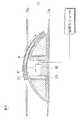
図1は、本発明の第1の実施形態に係るポインティングデバイスの分解斜視図であり、図2は、本発明の第1の実施形態に係るポインティングデバイスの断面図であり、図3は、本発明の第1の実施形態に係るポインティングデバイスの結合断面図である。 1 is an exploded perspective view of the pointing device according to the first embodiment of the present invention, FIG. 2 is a cross-sectional view of the pointing device according to the first embodiment of the present invention, and FIG. 1 is a cross-sectional view of a pointing device according to a first embodiment of the present invention.
図1ないし図3に示すように、本発明の第1の実施形態に係るポインティングデバイスは、ハウジング本体10と、曲面支持部20と、ポインティング部30と、センサ部40と、制御モジュール50とを備えて構成される。 As shown in FIGS. 1 to 3, the pointing device according to the first embodiment of the present invention includes a
ハウジング本体10は、後述する曲面支持部20と、ポインティング部30と、センサ部40とが内設され得る通常の携帯用コンピュータの外部ハウジング、または携帯電話、あるいはPDAなどのモバイル機器の外部ハウジングでありうる。これにより、ハウジング本体10は、上部パネル10aと下部パネル10bとで構成され、上部パネル10aと下部パネル10bとは、所定の間隔を維持するように互いに離隔して向かい合っている形態で設けられる。 The
一方、上部パネル10aは、所定領域に後述するポインティング部30の上部の一部が外部に露出するように所定領域に孔11が形成される。 On the other hand, in the
曲面支持部20は、曲面を有した形態であって、凹曲面また凸曲面が形成され得る。本実施形態では、球の一部を切断した形態である凸形態の曲面を仮定して説明する。 The curved
曲面支持部20は、球の一部を切断した形態であって、球の曲面21及び切断された面の基底部22を備えている。また、曲面支持部20の内側には、後述するセンサ部40が収容されて定着され得るように、上方に開口を有する溝形態のセンサ定着部23が形成され得る。このとき、センサ定着部23は、曲面支持部20の中央部に形成されることが好ましい。また、前記センサ定着部23は、孔形態で形成されることもできる。 The curved
一方、磁力部は、センサ定着部23の隣接領域に設置される第1の磁力部24と、前記隣接領域の外側に設置された第2の磁力部25と、後述するポインティング部30に内設される第3の磁力部33とを備えて構成される。 On the other hand, the magnetic part is installed in the first
ここで、前記磁力部のうち、曲面支持部20の内部には、センサ定着部23の隣接領域と、曲面21の隣接領域と、基底部22の隣接領域とに至る領域まで第1の磁力部24と第2の磁力部25とが設置される。このとき、前記第1の磁力部24と前記第2の磁力部25とは、互いに反対の極性を有することが好ましい。 Here, among the magnetic force portions, the first magnetic force portion is provided in the curved
すなわち、第1の磁力部24の極性がN極またはS極のうち、N極で設置されると、第2の磁力部25の極性はS極で設置され、第1の磁力部24の極性がS極で設置されると、第2の磁力部25の極性はN極で設置されることができる。 That is, when the polarity of the first
また、このような第1の磁力部24と第2の磁力部25とは、互いに異なる極性で設置され、後述するポインティング部30に設置される第3の磁力部33と相互作用することにより、曲面支持部20に沿って摺動された後のポインティング部30が元の位置に回復されるようになる。 In addition, the first
また、このような形態の曲面支持部20は、基底部22がハウジング本体10の下部パネル10bの上部に結合され、前記センサ定着部23と上部パネル10aの孔11とが向かい合うように結合されることができる。 Further, the curved
次に、ポインティング部30について説明する。ポインティング部30は、所定の厚さを有し、前記曲面支持部20のセンサ定着部23を覆うことができるように形成され得るが、曲面21の長さに比べて短かったり長く形成されることができ、望ましくは、曲面21の長さより短い長さ(曲面支持部の最上端地点から左側または右側終端部までの長さより短い長さ)で形成され得る。ただ、ポインティング部30の長さは移動の時センサ定着部23が露出しないように形成されることが好ましい。 Next, the pointing
また、ポインティング部30の底面であるポインティング移動部31は、前記曲面支持部20の曲面21に沿って摺動するように曲面21と対応する形態、すなわち、曲面21と同心球の形態で形成され得る。 In addition, the
一方、ポインティング部30の上面32は、ハウジング本体10の上部パネル10aによって支持された状態で、ポインティング移動部31が曲面21に沿って摺動するとき、上部パネル10aとの円滑な接触のために曲面形態で形成されることができ、望ましくは、ポインティング移動部31と同心球の形態で形成されることができる。 On the other hand, the
ここで、ポインティング部30の内部には、前記曲面支持部20の第1の磁力部24及び第2の磁力部25と同じ材質である第3の磁力部33が内設され得る。 Here, a third
前記第3の磁力部33の極性は、曲面支持部20の第1の磁力部24と反対であるため、引力が作用し、第2の磁力部25の極性とは同じ極性を有するように設置されることにより、斥力が作用してポインティング部30が曲面支持部20の曲面21に沿って摺動された後、元の位置に回復される。 Since the polarity of the third
また、ポインティング部30が曲面支持部20の上部に設置されることにより、曲面支持部20及びポインティング部30に設けられた各々の第1の磁力部24と、第2の磁力部25と、第3の磁力部33との磁力が相互作用するようになり、ポインティング部30は、曲面支持部20の中央領域、すなわち、センサ定着部23の上部に位置できるようになる。 Further, since the
このとき、前記ハウジング本体10の上部パネル10aによってポインティング部30が支持されているので、より安定的に曲面支持部20の上部に位置できるようになる。 At this time, since the pointing
また、ポインティング部30は、前記ハウジング本体10の上部パネル10aに形成された孔11を介して上部の一部が露出していることにより、ユーザがポインティング部30に一方向に外力を加えると、前記ポインティング部30が曲面支持部20の曲面21に沿って摺動されるようにすることができる。 In addition, since the
次に、センサ部40及び制御モジュール50について説明する。センサ部40は、曲面支持部20のセンサ定着部23に収容されて定着した状態で、曲面支持部20の曲面21に沿って摺動するポインティング部30のポインティング移動部31の動きを感知するように設置され得る。ここで、センサ部40がセンシングするポイントは、ポインティング移動部31の1地点、すなわち、1ポイントのみをセンシングするように設置されることが好ましいが、複数個のセンサを用いてセンシングできるように設置されることもできる。 Next, the
このとき、センサ部40は、ポインティング部30の外部に露出しないポインティング移動部31をセンシングするように設置されることにより、従来、ボールの外部露出部分をセンシングして発生する問題を改善することができるという効果がある。 At this time, the
制御モジュール50は、センサ部40に接続されており、センサ部40がセンシングしたポインティング移動部31の動きを伝送され、所定のアルゴリズムによって画面上にポインティング部30の動きを表示可能なように構成されることができ、望ましくは、画面上のマウスポインタをポインティング移動部30の動きに対応して移動させるように構成される。 The control module 50 is connected to the
このとき、制御モジュール50は、ポインティング部30が曲面21に沿って摺動した後、曲面支持部20の第1の磁力部24とポインティング部30の第3の磁力部33との相互間に作用する引力と、曲面支持部20の第2の磁力部25とポインティング部30の第3の磁力部33との相互間に作用する斥力によって元の位置に戻る場合には、マウスポインタを移動しないように構成されることができる。 At this time, after the
一方、本発明の第1の実施形態では、磁力部を用いてポインティング部が曲面支持部の曲面に沿って摺動するように構成されているが、所定のばねを用いてポインティング部が移動した後、弾性回復するように構成されることもできる。 On the other hand, in the first embodiment of the present invention, the pointing part is configured to slide along the curved surface of the curved surface support part using the magnetic part, but the pointing part is moved using a predetermined spring. Later, it may be configured to recover elastically.
このように構成された本発明の第1の実施形態に係るポインティングデバイスは、従来のボールマウスの長所であるマウスポインタの微細な動きを実現することができる一方、限定的な空間でも設置されることができ、携帯機器のような制限された空間内に容易に設置されることができるという長所がある。 The pointing device according to the first embodiment of the present invention configured as described above can realize a fine movement of the mouse pointer, which is an advantage of the conventional ball mouse, but is also installed in a limited space. It can be easily installed in a limited space such as a portable device.
次いで、上述したポインティングデバイスの第1の実施形態の作動について説明する。 Next, the operation of the above-described pointing device according to the first embodiment will be described.
図4ないし図6は、本発明の第1の実施形態に係るポインティングデバイスの作動状態を示している。図4ないし図6を参照すると、図4のように、最初、ポインティング部30が移動する前の状態では、センサ部40がA地点をセンシングするようになる。 4 to 6 show the operating state of the pointing device according to the first embodiment of the present invention. 4 to 6, as shown in FIG. 4, in the state before the
その後、図5のように、ユーザがポインティング部30に右側方向に所定の力を加えると、ポインティング部30は、曲面21に沿って移動するようになり、このとき、センサ部40は、A’地点をセンシングするようになる。すなわち、A地点からA’地点までポインティング部30は曲面21に沿って摺動し移動するようになるものであり、センサ部40は、A地点からA’地点までのポインティング移動部31の各ポイントをセンシングするとともに、センシングされた信号を制御モジュール50に伝送するようになる。これと同時に、センサ部40でセンシングされた信号を伝送された制御モジュール50は、所定のアルゴリズムによってポインティング部30の摺動に対応するように、画面上のマウスポインタを移動させるものである。 Thereafter, as shown in FIG. 5, when the user applies a predetermined force to the
その後、ユーザがポインティング部30に加える力を解除するようになると、図6のように、曲面支持部20の第1の磁力部24とポインティング部30の第3の磁力部33とは互いに異なる極性で構成されて引力が作用し、曲面支持部20の第2の磁力部25とポインティング部30の第3の磁力部33とは互いに同じ極性で構成されて斥力が作用することにより、ポインティング部30は元の位置に移動できるようになる。 Thereafter, when the user releases the force applied to the pointing
このとき、ポインティング部30の上部に位置する上部パネル10aによって支持されており、円滑に元の位置に戻ることができるようになる。 At this time, it is supported by the
一方、制御モジュール50は、ポインティング部30が第1の磁力部24と第3の磁力部33とによって元の位置に移動するものであるため、画面上のマウスポインタは移動させない。 On the other hand, the control module 50 does not move the mouse pointer on the screen because the
上述した方向以外に、ユーザがいずれの方向にポインティング部30に力を加えて摺動させる場合にも、同じ方法で画面上のマウスポインタを移動させることができる。 In addition to the directions described above, the mouse pointer on the screen can be moved by the same method when the user slides the
このように、外部に露出していない部分をセンシングしてマウスポインタを動作させることができることにより、センサ部の誤作動防止及び寿命を向上させることができる。 As described above, since the mouse pointer can be operated by sensing a portion that is not exposed to the outside, it is possible to prevent malfunction of the sensor unit and improve its life.
また、曲面の曲率に変化を与えることができ、様々な大きさに変形適用が可能なだけでなく、薄い厚さを要求するモバイル機器のハウジング本体にも適するように設計できるという長所がある。 In addition, the curvature of the curved surface can be changed, and not only can the deformation be applied to various sizes, but also it can be designed to be suitable for a housing body of a mobile device that requires a small thickness.
本発明の権利範囲は上述した実施形態に限定されるものではなく、添付した特許請求の範囲内で様々な形態の実施形態によって実現できる。特許請求の範囲で請求する本発明の要旨を逸脱することなく、当該発明の属する技術分野における通常の知識を有した者であれば誰でも変形可能な多様な範囲まで本発明の請求の範囲の記載の範囲内にあるものとみなす。 The scope of rights of the present invention is not limited to the above-described embodiments, and can be realized by various embodiments within the scope of the appended claims. Without departing from the gist of the present invention claimed in the claims, anyone with ordinary knowledge in the technical field to which the invention belongs can be modified to various extents that can be transformed. It is considered to be within the scope of the description.
本発明の産業上利用可能性は、近年次第に小型化されつつ、携帯性を強調しているノートブック、PDA、またはモバイル機器などの様々な携帯機器に別途のマウスを備えなくとも微細な動きを感知できるポインティングデバイスを設置することができることにより、ユーザにとって優れた感度のポインティングデバイスを提供することができ、微細な動きを必要とする作業者などに携帯機器の利便性を提供することができるようになる。 The industrial applicability of the present invention has been gradually miniaturized in recent years, and it has been able to move finely even without a separate mouse in various portable devices such as notebooks, PDAs, or mobile devices that emphasize portability. By being able to install a pointing device that can be sensed, it is possible to provide a pointing device with excellent sensitivity for a user, and to provide convenience of a portable device to an operator who requires fine movement. become.
10 ・・・ ハウジング本体
10a ・・・ 上部パネル
10b ・・・ 下部パネル
11 ・・・ 孔
20 ・・・ 曲面支持部
21 ・・・ 曲面
22 ・・・ 基底部
23 ・・・ センサ定着部
24 ・・・ 第1の磁力部
25 ・・・ 第2の磁力部
30 ・・・ ポインティング部
31 ・・・ ポインティング移動部
32 ・・・ 上面
33 ・・・ 第3の磁力部
40 ・・・ センサ部
50 ・・・ 制御モジュールDESCRIPTION OF
Claims (7)
Translated fromJapanese該曲面支持部の上部に位置し、前記曲面支持部の曲面に沿って摺動されるように設置されるポインティング部と、
該ポインティング部の動きを感知するセンサ部と、
を備え、
前記ポインティング部が、前記曲面支持部の曲面に沿って摺動する移動量に対応して、画面上にポインティング部の動きを表わすことを特徴とするポインティングデバイス。A curved surface support including a curved surface;
A pointing unit that is positioned above the curved surface support portion and is slid along the curved surface of the curved surface support portion;
A sensor unit for sensing movement of the pointing unit;
With
The pointing device according to claim 1, wherein the pointing unit represents a movement of the pointing unit on a screen in accordance with an amount of movement along the curved surface of the curved surface supporting unit.
The control unit according to claim 1, further comprising a control module provided on the screen to represent the movement of the pointing unit corresponding to the amount of movement along the curved surface of the curved surface supporting unit. The pointing device according to any one of 1 to 6.
Applications Claiming Priority (2)
| Application Number | Priority Date | Filing Date | Title |
|---|---|---|---|
| KR1020080020175AKR100909546B1 (en) | 2008-03-04 | 2008-03-04 | Pointing device |
| PCT/KR2009/000896WO2009110694A1 (en) | 2008-03-04 | 2009-02-25 | Pointing device |
Publications (1)
| Publication Number | Publication Date |
|---|---|
| JP2011513852Atrue JP2011513852A (en) | 2011-04-28 |
Family
ID=41056214
Family Applications (1)
| Application Number | Title | Priority Date | Filing Date |
|---|---|---|---|
| JP2010549559APendingJP2011513852A (en) | 2008-03-04 | 2009-02-25 | pointing device |
Country Status (5)
| Country | Link |
|---|---|
| US (1) | US20110006989A1 (en) |
| JP (1) | JP2011513852A (en) |
| KR (1) | KR100909546B1 (en) |
| CN (1) | CN101796473A (en) |
| WO (1) | WO2009110694A1 (en) |
Cited By (1)
| Publication number | Priority date | Publication date | Assignee | Title |
|---|---|---|---|---|
| WO2015029335A1 (en)* | 2013-08-27 | 2015-03-05 | 株式会社デンソー | Manipulation device |
Citations (6)
| Publication number | Priority date | Publication date | Assignee | Title |
|---|---|---|---|---|
| WO1992021084A1 (en)* | 1991-05-15 | 1992-11-26 | Fujitsu Limited | Pointing device and controlling method therefor |
| JPH09212292A (en)* | 1996-02-01 | 1997-08-15 | Matsushita Electric Ind Co Ltd | Coordinate input device |
| JPH10207616A (en)* | 1997-01-20 | 1998-08-07 | Sharp Corp | Input device |
| JPH11203037A (en)* | 1998-01-12 | 1999-07-30 | Smk Corp | Coordinate input device |
| JP2000276294A (en)* | 1999-03-23 | 2000-10-06 | Hosiden Corp | Pointing device |
| WO2004066138A1 (en)* | 2003-01-20 | 2004-08-05 | Asahi Kasei Emd Corporation | Pointing device |
Family Cites Families (7)
| Publication number | Priority date | Publication date | Assignee | Title |
|---|---|---|---|---|
| US5889236A (en)* | 1992-06-08 | 1999-03-30 | Synaptics Incorporated | Pressure sensitive scrollbar feature |
| KR19990001106A (en)* | 1997-06-12 | 1999-01-15 | 윤종용 | Personal Computer Input and Locator (MOUSE) |
| JP4233174B2 (en)* | 1999-04-30 | 2009-03-04 | 富士通コンポーネント株式会社 | pointing device |
| JP2004133703A (en)* | 2002-10-10 | 2004-04-30 | Fujitsu Component Ltd | Pointing device and portable information device |
| US7429976B2 (en) | 2003-11-24 | 2008-09-30 | Avago Technologies Ecbu Ip (Singapore) Pte. Ltd. | Compact pointing device |
| US7423628B2 (en)* | 2004-02-27 | 2008-09-09 | Research In Motion Limited | Track wheel with reduced space requirements |
| JP2005250595A (en)* | 2004-03-01 | 2005-09-15 | Nec Saitama Ltd | Portable terminal |
- 2008
- 2008-03-04KRKR1020080020175Apatent/KR100909546B1/ennot_activeExpired - Fee Related
- 2009
- 2009-02-25USUS12/919,585patent/US20110006989A1/ennot_activeAbandoned
- 2009-02-25CNCN200980100007Apatent/CN101796473A/enactivePending
- 2009-02-25JPJP2010549559Apatent/JP2011513852A/enactivePending
- 2009-02-25WOPCT/KR2009/000896patent/WO2009110694A1/enactiveApplication Filing
Patent Citations (6)
| Publication number | Priority date | Publication date | Assignee | Title |
|---|---|---|---|---|
| WO1992021084A1 (en)* | 1991-05-15 | 1992-11-26 | Fujitsu Limited | Pointing device and controlling method therefor |
| JPH09212292A (en)* | 1996-02-01 | 1997-08-15 | Matsushita Electric Ind Co Ltd | Coordinate input device |
| JPH10207616A (en)* | 1997-01-20 | 1998-08-07 | Sharp Corp | Input device |
| JPH11203037A (en)* | 1998-01-12 | 1999-07-30 | Smk Corp | Coordinate input device |
| JP2000276294A (en)* | 1999-03-23 | 2000-10-06 | Hosiden Corp | Pointing device |
| WO2004066138A1 (en)* | 2003-01-20 | 2004-08-05 | Asahi Kasei Emd Corporation | Pointing device |
Cited By (3)
| Publication number | Priority date | Publication date | Assignee | Title |
|---|---|---|---|---|
| WO2015029335A1 (en)* | 2013-08-27 | 2015-03-05 | 株式会社デンソー | Manipulation device |
| JP2015045931A (en)* | 2013-08-27 | 2015-03-12 | 株式会社デンソー | Operation device |
| US10013080B2 (en) | 2013-08-27 | 2018-07-03 | Denso Corporation | Manipulation apparatus |
Also Published As
| Publication number | Publication date |
|---|---|
| KR100909546B1 (en) | 2009-07-27 |
| US20110006989A1 (en) | 2011-01-13 |
| CN101796473A (en) | 2010-08-04 |
| WO2009110694A1 (en) | 2009-09-11 |
Similar Documents
| Publication | Publication Date | Title |
|---|---|---|
| JP6516813B2 (en) | Standardization of pressure sensitive keys | |
| US20030006959A1 (en) | Method of operating a handheld device for directional input | |
| US20090033620A1 (en) | Portable Electronic Device and Touch Pad Device for the Same | |
| JP2006164275A (en) | System and directional input device for displaying images in a plurality of directions | |
| CN112578902A (en) | Finger wearable input assembly for controlling an electronic device | |
| US20090071808A1 (en) | Rotary input apparatus | |
| JP2010527470A (en) | Variable electronic device | |
| JP2014127155A (en) | Key input device | |
| JP6065984B2 (en) | Electronic equipment and hinge unit | |
| KR20100005872A (en) | Digital processing unit having key input unit and key input method | |
| US8624759B2 (en) | Apparatus and method for an actuator in an electronic device | |
| JPH04125723A (en) | Pointing controller | |
| EP1825460B1 (en) | Pointing device with extended travel | |
| US8203544B2 (en) | Input device and mobile communication device having same | |
| JP6864532B2 (en) | Input device, information processing device and manufacturing method of input device | |
| US7356769B2 (en) | Method and apparatus for providing inputs to a communication or computing device | |
| JP2011513852A (en) | pointing device | |
| CN101359264A (en) | Portable electronic device and touch pad device thereof | |
| US8885846B2 (en) | Electronic device | |
| KR20020014430A (en) | Portable wireless terminal with a pointing device | |
| JP2005228043A (en) | Equipment having jog dial input device and display using the same | |
| JP2006073249A (en) | Portable apparatus | |
| US20120026087A1 (en) | Movable operation plate module and electronic device with the same | |
| JP2005228043A5 (en) | ||
| JP6721199B1 (en) | Pointing device and electronic equipment |
Legal Events
| Date | Code | Title | Description |
|---|---|---|---|
| A131 | Notification of reasons for refusal | Free format text:JAPANESE INTERMEDIATE CODE: A131 Effective date:20120515 | |
| A977 | Report on retrieval | Free format text:JAPANESE INTERMEDIATE CODE: A971007 Effective date:20120516 | |
| A02 | Decision of refusal | Free format text:JAPANESE INTERMEDIATE CODE: A02 Effective date:20121016 |