JP2011512693A - Synchronization method and apparatus therefor - Google Patents
Synchronization method and apparatus thereforDownload PDFInfo
- Publication number
- JP2011512693A JP2011512693AJP2010530436AJP2010530436AJP2011512693AJP 2011512693 AJP2011512693 AJP 2011512693AJP 2010530436 AJP2010530436 AJP 2010530436AJP 2010530436 AJP2010530436 AJP 2010530436AJP 2011512693 AJP2011512693 AJP 2011512693A
- Authority
- JP
- Japan
- Prior art keywords
- signal
- transceiver
- pulse
- tag
- reader
- Prior art date
- Legal status (The legal status is an assumption and is not a legal conclusion. Google has not performed a legal analysis and makes no representation as to the accuracy of the status listed.)
- Granted
Links
- 238000000034methodMethods0.000titleclaimsabstractdescription160
- 230000005540biological transmissionEffects0.000claimsabstractdescription111
- 230000006854communicationEffects0.000claimsabstractdescription77
- 238000004891communicationMethods0.000claimsabstractdescription77
- 230000001172regenerating effectEffects0.000claimsabstractdescription61
- 238000001514detection methodMethods0.000claimsdescription100
- 238000010791quenchingMethods0.000claimsdescription42
- 230000004044responseEffects0.000claimsdescription39
- 230000010355oscillationEffects0.000claimsdescription23
- 238000012360testing methodMethods0.000claimsdescription14
- 230000008859changeEffects0.000claimsdescription4
- 238000004590computer programMethods0.000claimsdescription3
- 238000012795verificationMethods0.000description25
- 238000010586diagramMethods0.000description22
- 230000001360synchronised effectEffects0.000description20
- 230000008569processEffects0.000description12
- 101100368149Mus musculus Sync geneProteins0.000description10
- 230000008901benefitEffects0.000description10
- 239000003999initiatorSubstances0.000description10
- 230000015654memoryEffects0.000description9
- 238000012546transferMethods0.000description9
- 238000001208nuclear magnetic resonance pulse sequenceMethods0.000description6
- 230000007704transitionEffects0.000description6
- 238000000411transmission spectrumMethods0.000description6
- 230000000875corresponding effectEffects0.000description5
- 238000005259measurementMethods0.000description5
- 238000012545processingMethods0.000description5
- 230000003111delayed effectEffects0.000description4
- 238000001228spectrumMethods0.000description4
- 238000005516engineering processMethods0.000description3
- 230000006870functionEffects0.000description3
- 230000006872improvementEffects0.000description3
- 230000008929regenerationEffects0.000description3
- 238000011069regeneration methodMethods0.000description3
- 230000003321amplificationEffects0.000description2
- 238000013459approachMethods0.000description2
- 238000012937correctionMethods0.000description2
- 230000000694effectsEffects0.000description2
- 230000007246mechanismEffects0.000description2
- 238000003199nucleic acid amplification methodMethods0.000description2
- 230000001105regulatory effectEffects0.000description2
- 230000035945sensitivityEffects0.000description2
- 238000007493shaping processMethods0.000description2
- 230000001960triggered effectEffects0.000description2
- VCUFZILGIRCDQQ-KRWDZBQOSA-NN-[[(5S)-2-oxo-3-(2-oxo-3H-1,3-benzoxazol-6-yl)-1,3-oxazolidin-5-yl]methyl]-2-[[3-(trifluoromethoxy)phenyl]methylamino]pyrimidine-5-carboxamideChemical compoundO=C1O[C@H](CN1C1=CC2=C(NC(O2)=O)C=C1)CNC(=O)C=1C=NC(=NC=1)NCC1=CC(=CC=C1)OC(F)(F)FVCUFZILGIRCDQQ-KRWDZBQOSA-N0.000description1
- 230000004913activationEffects0.000description1
- 230000002411adverseEffects0.000description1
- 230000006399behaviorEffects0.000description1
- 230000009286beneficial effectEffects0.000description1
- 230000007175bidirectional communicationEffects0.000description1
- 230000002457bidirectional effectEffects0.000description1
- 230000015572biosynthetic processEffects0.000description1
- 238000012790confirmationMethods0.000description1
- 230000002596correlated effectEffects0.000description1
- 230000009977dual effectEffects0.000description1
- 239000000463materialSubstances0.000description1
- 238000012986modificationMethods0.000description1
- 230000004048modificationEffects0.000description1
- 230000001151other effectEffects0.000description1
- 230000000737periodic effectEffects0.000description1
- 238000000819phase cycleMethods0.000description1
- 230000000171quenching effectEffects0.000description1
- 230000009467reductionEffects0.000description1
- 238000001028reflection methodMethods0.000description1
- 238000005316response functionMethods0.000description1
- 230000002441reversible effectEffects0.000description1
- 102220198146rs1057519886Human genes0.000description1
- 238000000926separation methodMethods0.000description1
- 230000008054signal transmissionEffects0.000description1
- 230000003595spectral effectEffects0.000description1
- 230000007480spreadingEffects0.000description1
- 238000003786synthesis reactionMethods0.000description1
- 230000008685targetingEffects0.000description1
Images


Classifications
- H—ELECTRICITY
- H04—ELECTRIC COMMUNICATION TECHNIQUE
- H04B—TRANSMISSION
- H04B1/00—Details of transmission systems, not covered by a single one of groups H04B3/00 - H04B13/00; Details of transmission systems not characterised by the medium used for transmission
- H04B1/69—Spread spectrum techniques
- H04B1/7163—Spread spectrum techniques using impulse radio
- H04B1/7183—Synchronisation
- H—ELECTRICITY
- H04—ELECTRIC COMMUNICATION TECHNIQUE
- H04B—TRANSMISSION
- H04B7/00—Radio transmission systems, i.e. using radiation field
- H04B7/14—Relay systems
- H04B7/15—Active relay systems
- H04B7/204—Multiple access
- H04B7/212—Time-division multiple access [TDMA]
- H04B7/2125—Synchronisation
- H—ELECTRICITY
- H04—ELECTRIC COMMUNICATION TECHNIQUE
- H04L—TRANSMISSION OF DIGITAL INFORMATION, e.g. TELEGRAPHIC COMMUNICATION
- H04L1/00—Arrangements for detecting or preventing errors in the information received
- H04L1/004—Arrangements for detecting or preventing errors in the information received by using forward error control
- H04L1/0041—Arrangements at the transmitter end
- H—ELECTRICITY
- H04—ELECTRIC COMMUNICATION TECHNIQUE
- H04L—TRANSMISSION OF DIGITAL INFORMATION, e.g. TELEGRAPHIC COMMUNICATION
- H04L1/00—Arrangements for detecting or preventing errors in the information received
- H04L1/004—Arrangements for detecting or preventing errors in the information received by using forward error control
- H04L1/0045—Arrangements at the receiver end
Landscapes
- Engineering & Computer Science (AREA)
- Computer Networks & Wireless Communication (AREA)
- Signal Processing (AREA)
- Near-Field Transmission Systems (AREA)
Abstract
Translated fromJapaneseDescription
Translated fromJapanese本発明は、送受信機を入来信号に同期させるための方法および装置に関する。具体的には、本発明は、第1の送受信機と第2の送受信機との間のパルス超広帯域(UWB)無線周波数(RF)通信などのパルス無線通信を同期させるための方法および装置に関するが、これに限られるものではない。 The present invention relates to a method and apparatus for synchronizing a transceiver to an incoming signal. Specifically, the present invention relates to a method and apparatus for synchronizing pulsed radio communications, such as pulsed ultra-wideband (UWB) radio frequency (RF) communications between a first transceiver and a second transceiver. However, it is not limited to this.
無線自動識別(RFID)の分野が徐々に進歩するにつれ、10Mビット/秒以上の規模の高速のデータ転送速度を有するRFIDシステムに対する要求が増加している。高ビットレートのRFIDシステムに対する要求は、継続的に不揮発性メモリの電力消費が低くなってきておりかつ価格が安くなってきていることに基づいている。価格および電力消費を低下させることに関して新たな見解をもたらす、より新規のメモリ技術が次第に開発されてきている。メモリ技術の発展により、リーダまたは別の装置によって遠隔的に駆動されるパッシブRFIDタグにおいて、メガ〜ギガバイト規模のサイズの大容量メモリを使用することが可能となる。しかしながら、現在のRFIDのエア・インターフェースは、一般に数百キロビット/秒程度までのデータ転送速度を支援し、かつ主に連続波信号の後方散乱および変調に基づく。しかしながらそのような方法には、性能に関していくつか技術的に限界があり、特に、RFIDリーダの機能が、物理的に寸法の小さい装置に組み込まれるときに、これらの限界があることを強く感じる。 As the field of wireless automatic identification (RFID) gradually advances, there is an increasing demand for RFID systems with high data transfer rates on the order of 10 Mbit / s or more. The demand for high bit rate RFID systems is based on the continually lower consumption of non-volatile memories and lower prices. Newer memory technologies are increasingly being developed that provide new insights on reducing price and power consumption. Advances in memory technology have enabled the use of large-capacity memories on the order of mega to gigabytes in passive RFID tags that are driven remotely by a reader or another device. However, current RFID air interfaces typically support data rates up to several hundred kilobits per second and are primarily based on backscattering and modulation of continuous wave signals. However, such methods have some technical limitations on performance, and I feel strongly that these limitations are present, especially when the functionality of the RFID reader is incorporated into a physically smaller device.
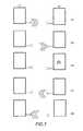
インパルス無線ベースのUWBは、広帯域幅が利用可能であるため高速データ転送速度通信アプリケーションに対して興味深い解決法を提供する。連続搬送周波数を変調するというよりは、パルスUWB通信は短パルス信号の伝送に基づいている。図1に示すように、変調は、パルス信号の有無(OOK変調)、パルス信号位置(PPM)またはパルス極性(B−PSK)に基づいて行うことができる。短パルス信号の持続期間のために、周波数スペクトルの幅は広い。シャノン(Shannon)理論によれば、これにより、伝統的な狭帯域の解決法で達成できるものよりも高速のデータ転送速度を達成することが可能となる。 Impulse radio based UWB offers an interesting solution for high data rate communication applications because of the wide bandwidth available. Rather than modulating the continuous carrier frequency, pulse UWB communication is based on the transmission of short pulse signals. As shown in FIG. 1, the modulation can be performed based on the presence or absence of a pulse signal (OOK modulation), the pulse signal position (PPM), or the pulse polarity (B-PSK). Due to the duration of the short pulse signal, the frequency spectrum is wide. According to Shannon theory, this makes it possible to achieve higher data transfer rates than can be achieved with traditional narrowband solutions.
UWBは、利用可能な帯域幅が広いので、1パルスの持続期間がデータのシンボル持続期間よりも遙かに短い、非常に短いパルスを伝送し得る。これは、システムの低デューティサイクルをもたらす。例として、目標とするデータ転送速度が10Mビット/秒である場合、最大シンボル間隔は100ns/シンボルである。しかしながら、UWBパルス持続期間は、例えば1〜10nsと、それよりも遙かに短い場合がある。10nsのパルス持続期間を用いても、デューティサイクルは10%にすぎない。より短いパルスの場合には、当然ながらデューティサイクルはさらに低くなる。エア・インターフェースにおける低デューティサイクルは、好都合にも、送受信機の電力消費に直接利用することができる。デューティサイクルに依存して、例えば時間の10%、送受信機をアクティブにのみ保つことを必要とし得る。これを可能とするためには、送信装置と受信装置との間の周波数および位相同期が良好である必要がある。実際には、通常、受信機のタイミングを伝送に適合させることは、その逆を行うことよりも簡単であり、それゆえ、作業の大部分は一般に、受信側において、伝送されたパルス信号の受信機による受信を同期させることにある。通信を開始する装置、例えばRFIDリーダは、一般に連続RF波を伝送して、他方の側、例えばRFIDタグをパワーアップし、かつ両側に対して共通のクロック基準としての機能を果たして、両側が同じ周波数で確実に動作できるようにする。インパルスUWBによるデータ通信が可能となる前に、協働する装置間の位相同期を達成する必要がある。 Because UWB has a wide bandwidth available, it can transmit very short pulses, where the duration of one pulse is much shorter than the symbol duration of the data. This results in a low duty cycle for the system. As an example, if the target data rate is 10 Mbit / s, the maximum symbol interval is 100 ns / symbol. However, the UWB pulse duration may be much shorter, for example 1-10 ns. Even with a 10 ns pulse duration, the duty cycle is only 10%. Of course, for shorter pulses, the duty cycle is even lower. The low duty cycle at the air interface can be advantageously used directly for transceiver power consumption. Depending on the duty cycle, it may be necessary to keep the transceiver only active, for example 10% of the time. In order to make this possible, the frequency and phase synchronization between the transmitting device and the receiving device needs to be good. In practice, it is usually easier to adapt the timing of the receiver to the transmission than to do the reverse, so the majority of the work is generally done at the receiver side to receive the transmitted pulse signal. It is to synchronize reception by the machine. A device that initiates communication, such as an RFID reader, generally transmits a continuous RF wave, powers up the other side, eg, an RFID tag, and serves as a common clock reference for both sides, both sides being the same Ensure reliable operation at frequency. Before data communication by impulse UWB is possible, it is necessary to achieve phase synchronization between cooperating devices.
UWB通信における周波数および位相同期は、多くの課題を示す。特に、伝送は連続的ではなくパルス的に行われるため、通信装置の送受信機が連続的にアクティブではない場合、すなわち受信機の検出が不連続である場合、受信装置のアクティブな受信期間のタイミングを何らかの方法で、送信装置から伝送された入来信号と同期させる必要がある。そうでなければ、受信装置は、送信装置によって伝送された入来信号を受信しそこなう可能性が高い。それゆえ、受信装置のアクティブな受信期間を、送信機からの信号の伝送に同期させる必要がある。 Frequency and phase synchronization in UWB communication presents many challenges. In particular, since the transmission is performed in pulses rather than continuously, the timing of the active receiving period of the receiving device when the transceiver of the communication device is not continuously active, ie when the detection of the receiver is discontinuous. Must be synchronized with the incoming signal transmitted from the transmitter in some way. Otherwise, the receiving device is likely to miss the incoming signal transmitted by the transmitting device. It is therefore necessary to synchronize the active reception period of the receiving device with the transmission of the signal from the transmitter.
大容量メモリタグの遠隔的な駆動および最大通信距離を実現可能とするには、RFIDタグの電力が極めて最適にされかつ可能な限り低く保たれていることを必要とする。結果として、PLL(位相ロックループ)やDLL(遅延ロックループ)のような、電力を多く必要とする(power hungry)高周波数合成およびデジタルトラッキングシステムを、十分な周波数および位相同期のためにタグに実装すべきではない。なぜなら、そうでなければ、電力消費量が、遠隔的な駆動を実行不可能にするレベルまで容易に高くなり得るためである。 In order to be able to achieve remote drive and maximum communication distance of a large capacity memory tag, the power of the RFID tag needs to be very optimized and kept as low as possible. As a result, power hungry high frequency synthesis and digital tracking systems, such as PLLs (Phase Locked Loops) and DLLs (Delayed Locked Loops), can be added to tags for sufficient frequency and phase synchronization. Should not be implemented. This is because otherwise power consumption can easily be increased to a level that makes remote driving infeasible.
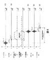
UWBインパルス無線の同期を妨害する別の要素は、UWB透過スペクトルに対する規制である。UWBシステムでは、伝送信号に存在するパルスの繰り返しがもたらすスペクトル線を取り除くために、長い拡散シーケンス(時間ホッピング符号(time−hopping code))が必要とされる。図2に、一例として、オンオフキーイング変調を使用する、時間区間における時間ホッピングの原理を示す。このオンオフキーイング変調は、UWBインパルス無線でよく使用される。符号シーケンスをまた、複数のユーザアクセスに効果的に使用することもできる。 Another factor that hinders the synchronization of UWB impulse radio is the restriction on the UWB transmission spectrum. In a UWB system, a long spreading sequence (time-hopping code) is required to remove spectral lines caused by repetition of pulses present in the transmitted signal. FIG. 2 shows the principle of time hopping in a time interval using on-off keying modulation as an example. This on-off keying modulation is often used in UWB impulse radio. The code sequence can also be effectively used for multiple user access.
時間ホッピングの利点は透過スペクトルの観点から明らかであるため、時間ホッピングをUWBインパルス無線通信において使用することは興味深い。しかしながら、その使用は、より時間のかかる同期手順となる。なぜなら、信頼性のある通信リンクを築く前に、時間ホッピングスキームの位相についてシステムの送信機および受信機の双方が知っている必要があるためである。実際は、一定のパルス繰り返しにおいて、必要な反復ラウンド(round)の最大数は、そのまま、1つのシンボル内で取り得るパルス位置の数であり、その数は図2の例では4である。しかしながら、時間ホッピングスキームを使用する場合、必要な反復ラウンドの最大数は、時間ホッピングスキームに使用されたシンボルの数に、シンボル毎の時間ホッピング位置の数を乗じた数にまで増大する。容易に理解できるように、時間ホッピングを使用することにより、位相同期手順は時間がかかるものとなるが、平滑な透過スペクトルを達成するためには必要である。 It is interesting to use time hopping in UWB impulse radio communications because the advantages of time hopping are obvious from a transmission spectrum perspective. However, its use becomes a more time-consuming synchronization procedure. This is because both the transmitter and receiver of the system need to know the phase of the time hopping scheme before building a reliable communication link. In practice, the maximum number of repetition rounds required in a fixed pulse repetition is the number of pulse positions that can be taken in one symbol as it is, and the number is 4 in the example of FIG. However, when using a time hopping scheme, the maximum number of iteration rounds required increases to the number of symbols used in the time hopping scheme multiplied by the number of time hopping positions per symbol. As can be readily appreciated, the use of time hopping makes the phase synchronization procedure time consuming but is necessary to achieve a smooth transmission spectrum.
要するに、低出力のUWBインパルス無線システムにおける位相同期を難しいものにする主な要因のいくつかは:
・平均電力消費を妥当な水準に保つために必要な低デューティサイクル;および
・透過スペクトルを平滑に保つために必要なUWBパルスの時間ホッピング
である。In summary, some of the main factors that make phase synchronization difficult in low-power UWB impulse radio systems are:
The low duty cycle needed to keep the average power consumption at a reasonable level; and the time hopping of the UWB pulses needed to keep the transmission spectrum smooth.
2つ以上のUWB装置間の位相同期を見つけるための従来技術の方法は、参照シーケンスのタイミングをずらしかつ微調整することによって、入来パルスシーケンスと公知の参照符号シーケンスとの間の相関関係を求めることを伴う。受信信号と参照符号との間の位相が正しいとすぐに、相関ピークが出現する。この方法は、直列検索と呼ばれている。並列検索は代替的な方法であり、同期プロセスを迅速化する。それにもかかわらず、並列検索は、各ブランチが重複しているため複雑な回路受信機を必要とする。 Prior art methods for finding the phase synchronization between two or more UWB devices shifts and fine-tunes the timing of the reference sequence, thereby correlating the correlation between the incoming pulse sequence and the known reference code sequence. Entails seeking. As soon as the phase between the received signal and the reference code is correct, a correlation peak appears. This method is called serial search. Parallel search is an alternative method that speeds up the synchronization process. Nevertheless, parallel search requires complex circuit receivers because each branch is duplicated.
図3にそのような方法の図の例を示す。この例では、リーダは、時間ホッピング同期シーケンスを周期的に伝送する。相手方の装置、この場合はタグが、同期シーケンスを受け取り(listen)、かつ入力データを参照シーケンスに相関させる。各相関関係ラウンド後、入来シーケンスが最終的に参照シーケンスと合致するように、ポーズを入れてもよい。相関関係が十分高くなるとすぐに、タグ自体が、予め定められたタイムスロット中にリーダに情報を送信するための準備をし得る。しかしながら、平滑な透過スペクトルを達成するために時間ホッピングシーケンスは比較的長い必要があるため、特に、上述のように電力消費の最適化のためにシステムの両側において受信機のデューティサイクルが低い場合には、シーケンス間の正しい位相を見つけるのに時間がかかる。 FIG. 3 shows an example diagram of such a method. In this example, the reader periodically transmits a time hopping synchronization sequence. The counterpart device, in this case the tag, receives the synchronization sequence and correlates the input data to the reference sequence. After each correlation round, a pause may be made so that the incoming sequence eventually matches the reference sequence. As soon as the correlation is high enough, the tag itself can be ready to send information to the reader during a predetermined time slot. However, the time hopping sequence needs to be relatively long to achieve a smooth transmission spectrum, especially when the receiver duty cycle is low on both sides of the system to optimize power consumption as described above. Takes time to find the correct phase between sequences.
従来技術の直列検索同期方法の別の弱点は、エミッタにおいてではなく受信機側において複雑さがあることである。このために、従来技術の方法を使用するには、パッシブメモリタグの場合に、タグが入来符号シーケンスと公知の参照シーケンスとの間の相関を行うことが可能であることが必要となる。他の代替的な方法は、当然ながら、タグが同期シーケンスのエミッタであり、それにより、タグの複雑さの低減を図れる。通信フィールドに入り込むと、タグは、調整器の時間基準で同期パルスを送信し、かつリーダはそれ自体をタグの同期パルスに同期する必要がある。この挙動は、「タグトークファースト(tag talk first)」原理として周知である。しかしながら、そのような構造の欠点は衝突の管理であり、それは、このフィールドにあるまたは入る各タグがチャネルの飽和に寄与し得るためである。 Another weakness of prior art serial search synchronization methods is the complexity on the receiver side, not on the emitter. For this reason, the use of prior art methods requires that, in the case of passive memory tags, the tag can be correlated between the incoming code sequence and a known reference sequence. Another alternative is, of course, that the tag is the emitter of the synchronization sequence, thereby reducing the complexity of the tag. Upon entering the communication field, the tag transmits a sync pulse on the regulator's time base, and the reader needs to synchronize itself with the tag's sync pulse. This behavior is known as the “tag talk first” principle. However, a drawback of such a structure is collision management, since each tag in or entering this field can contribute to channel saturation.
拡散スペクトルシーケンスによる伝統的な直列検索方法に対するいくつかの改良方法が、上述の問題のいくつかに対処する試みにおいて、米国特許出願公開第2006/0093077号明細書に提案されている。この文献には、入力信号とテンプレートパルス列との間の相互相関に基づく同期方法が説明されている。しかしながら、システムは上述の問題の全てに対処しているわけではない。 Several improvements to the traditional serial search method with spread spectrum sequences have been proposed in US 2006/0093077 in an attempt to address some of the problems described above. This document describes a synchronization method based on cross-correlation between an input signal and a template pulse train. However, the system does not address all of the above issues.
直列検索同期手法の実施形態は、超再生アーキテクチャに基づく。このアーキテクチャは戦時中、レーダ識別用のパルス応答機に広く使用された。そのようなシステムでは、質問機が質問パルスを、識別されるべきトランスポンダに送信する。超再生の基本的な理論は、この間に確立された。最近では、超再生受信機の適用は、コスト削減および低電力消費が必要とされる狭帯域システムまで拡張されている。この技術は、ごく最近では、超再生アーキテクチャの最適化に関して新規な手法を含む超広帯域パルス通信まで拡張された。この技術では、送受信機間の双方向通信の同期に正確なタイミングが必要となる。それゆえ、超再生受信機に基づくUWB通信において同期問題に対処する電力効率方法が求められている。 An embodiment of the serial search synchronization approach is based on a super-regenerative architecture. This architecture was widely used in pulse response machines for radar identification during the war. In such a system, the interrogator sends an interrogation pulse to the transponder to be identified. The basic theory of super regeneration was established during this time. Recently, the application of super regenerative receivers has been extended to narrowband systems where cost reduction and low power consumption are required. Most recently, this technology has been extended to ultra-wideband pulse communications, including a novel approach for optimizing super-regenerative architectures. This technique requires accurate timing for synchronization of bidirectional communication between the transceivers. Therefore, there is a need for a power efficient method that addresses the synchronization problem in UWB communications based on super regenerative receivers.
超再生技術を使用することによって直面し得る問題は、例えば別の送受信機からの入来信号に応答してまたは雑音や他の干渉に起因して、協働する送受信機からの伝送パルスの入来がないときにも、送受信機における超再生機によって信号が発生することである。問題は、協働する送受信機からの意図的な入来パルスと、他の影響に起因する入来信号との区別が困難であることにある。 Problems that can be faced by using super-regenerative techniques are, for example, the input of transmission pulses from cooperating transceivers in response to incoming signals from another transceiver or due to noise or other interference. Even when it does not come, a signal is generated by the super regenerator in the transceiver. The problem is that it is difficult to distinguish between intentional incoming pulses from cooperating transceivers and incoming signals due to other effects.
本発明は、上述の問題を克服するまたは少なくとも改善するという一般的な目的によって、パルス無線通信における、具体的にはUWB通信における同期方法およびそのための装置を提供することを目指す。 The present invention aims to provide a synchronization method and apparatus for pulse radio communication, in particular UWB communication, with the general object of overcoming or at least improving the above-mentioned problems.
大まかに言えば、本発明は、第1の送受信機において、伝送パルスに応答して第2の送受信機によって伝送された反射パルスを検出することによって、第2の送受信機のアクティブ受信および検出タイムスロットと、第1の送受信機の伝送パルスとを同期させる方法を提供する。反射パルス情報を使用して、2つの装置の最適な位相同期を見つける。本発明の文脈では、用語「反射信号」は、第1の送受信機から伝送されて第2の送受信機において受信された入来伝送信号に応答して、第2の送受信機によって伝送される信号を指すことを理解されたい。反射信号は、受信された入来信号と時間的に離れていてもいなくてもよいことを理解されたい。 Broadly speaking, the present invention relates to the active reception and detection time of the second transceiver by detecting the reflected pulse transmitted by the second transceiver in response to the transmission pulse in the first transceiver. A method is provided for synchronizing a slot and a transmission pulse of a first transceiver. The reflected pulse information is used to find the optimal phase synchronization of the two devices. In the context of the present invention, the term “reflected signal” is a signal transmitted by a second transceiver in response to an incoming transmission signal transmitted from the first transceiver and received at the second transceiver. It should be understood that It should be understood that the reflected signal may or may not be temporally separated from the received incoming signal.
本発明の第1の態様では、方法(特に、パルス無線通信のための、第1の送受信機と第2の送受信機との間の同期方法)を提供し、その方法は:第1の送受信機から第2の送受信機へ伝送パルス信号を伝送すること;第2の送受信機において第2の送受信機のアクティブな受信タイムスロット期間内に伝送パルスが受信される場合、伝送パルス信号に応答して第2の送受信機から第1の送受信機へ反射信号を伝送すること;および反射信号を検出して、第1の送受信機と第2の送受信機との同期を判定することを含む。 In a first aspect of the invention, a method is provided, in particular a synchronization method between a first transceiver and a second transceiver for pulsed radio communication, the method comprising: first transmission / reception Transmitting a transmission pulse signal from the transmitter to the second transceiver; if the transmission pulse is received in the second transceiver within the active reception time slot period of the second transceiver, in response to the transmission pulse signal Transmitting a reflected signal from the second transceiver to the first transceiver; and detecting the reflected signal to determine synchronization between the first transceiver and the second transceiver.
本発明の第2の態様は、方法(特に、送受信機を、協働する送受信機と同期させる方法)を提供し、その方法は:協働する送受信機から伝送パルス信号を受信すること;伝送パルス信号に応答して反射信号を発生し、かつ伝送パルス信号が、送受信機のアクティブな受信タイムスロット期間内に受信される場合、反射信号を前記協働する送受信機に伝送して、受信した伝送パルス信号との同期を判定できるようにすることを含む。 A second aspect of the present invention provides a method, in particular a method of synchronizing a transceiver with a cooperating transceiver, the method comprising: receiving a transmission pulse signal from the cooperating transceiver; If a reflected signal is generated in response to the pulse signal and the transmitted pulse signal is received within the active receive time slot period of the transceiver, the reflected signal is transmitted to the cooperating transceiver and received. Including enabling determination of synchronization with the transmission pulse signal.
本発明の第3の態様は、方法(特に、送受信機を、協働する送受信機と同期させる方法)を提供し、その方法は、伝送パルス信号を伝送すること;伝送パルス信号が、協働する送受信機のアクティブな受信タイムスロット期間内に受信された場合、伝送パルス信号に応答して前記協働する送受信機によって伝送された反射信号を受信すること;および反射信号を検出して、協働する送受信機との同期を判定することを含む。 A third aspect of the present invention provides a method (especially a method of synchronizing a transceiver with a cooperating transceiver), the method transmitting a transmission pulse signal; Receiving a reflected signal transmitted by the cooperating transceiver in response to a transmitted pulse signal; and detecting the reflected signal when received within an active receive time slot period of the transmitting / receiving transceiver; Including determining synchronization with a working transceiver.
これらの態様のいずれか1つによる方法は、送受信機の電力消費が低デューティサイクルを用いて最適にされる低電力システムにおいてとりわけ有用であり、信号の伝送は、UWB規制に従って動作するインパルス無線の場合のように、擬似ランダム化時間ホッピングシーケンスを使用してまたは使用せずにパルス化される。そのような方法により、電力消費を最小限に保つことが可能になり、それにより、電力効率のよい同期方法を提供できる。 The method according to any one of these aspects is particularly useful in low power systems where the power consumption of the transceiver is optimized using a low duty cycle, and the transmission of signals is for an impulse radio that operates according to UWB regulations. As is the case, it is pulsed with or without a pseudo-randomized time hopping sequence. Such a method makes it possible to keep power consumption to a minimum, thereby providing a power efficient synchronization method.
さらに、従来技術方法と比べると、本発明の態様のいずれか1つによる方法は、直ちに確認応答を提供して、UWBインパルス無線通信における同期を確認する。確認応答情報に基づいて、UWB通信に伝統的に使用された方法と比べて同期処理を加速できる。なぜなら、本発明の一部の実施形態では、同期シーケンスの長さを単一の伝送パルスとし得るためである。 Furthermore, compared to prior art methods, the method according to any one of the aspects of the present invention immediately provides an acknowledgment to confirm synchronization in UWB impulse radio communications. Based on the acknowledgment information, the synchronization process can be accelerated compared to the methods traditionally used for UWB communication. This is because in some embodiments of the present invention, the length of the synchronization sequence may be a single transmission pulse.
さらに、反射信号は、反射を開始する伝送パルスが受信側によって検出されたことを示すことができ、それにより、受信側の代わりに伝送側において同期アルゴリズムを実施することが可能となる。それゆえ、RFIDリーダの場合、例えば、第1の送受信機をリーダとし、第2の送受信機を対応するタグとすることができる場合、同期アルゴリズムをタグにおいて実施する必要はなく、それにより、タグは電力消費が低くなり、かつより単純な回路アーキテクチャを有するようにできる。 Furthermore, the reflected signal can indicate that a transmission pulse that starts reflection has been detected by the receiving side, thereby allowing a synchronization algorithm to be implemented on the transmitting side instead of the receiving side. Thus, in the case of an RFID reader, for example, if the first transceiver can be the reader and the second transceiver can be the corresponding tag, the synchronization algorithm need not be implemented on the tag, thereby Can have lower power consumption and have a simpler circuit architecture.
高速データ転送速度のRFIDシステムにおいて本発明の実施形態による同期手順を用いることは、多くの利点を有し得る。同期アルゴリズムは、タグの観点からより単純であり、それにより、タグにおける電力消費を削減することが可能となる。大容量メモリでは、RFIDの実装、例えば、アルゴリズムの複雑さは、主に、一般にタグよりも、システムに関する電力消費条件が厳しくないリーダにある。さらに、同期方法は、2つの送受信機間の双方向通信を支援するものであり、それゆえRFIDシステムを、例えば、リーダおよびタグに、類似のRF送受信機構造を使用することにより、実装することができる。そのような同期方法はまた、多重アクセスに匹敵する。 Using a synchronization procedure according to embodiments of the present invention in a high data rate RFID system may have many advantages. The synchronization algorithm is simpler from the tag's point of view, which can reduce power consumption in the tag. For large-capacity memories, the complexity of RFID implementations, eg, algorithms, is primarily in the reader where the power consumption requirements for the system are generally less stringent than the tags. In addition, the synchronization method supports two-way communication between two transceivers, and therefore an RFID system can be implemented, for example, by using a similar RF transceiver structure for readers and tags. Can do. Such a synchronization method is also comparable to multiple access.
反射信号を発振器によって第2のまたは協働する送受信機において発生してもよい。本発明の実施形態によれば、反射信号は超再生発振器によって発生する。 The reflected signal may be generated by an oscillator at a second or cooperating transceiver. According to an embodiment of the invention, the reflected signal is generated by a super regenerative oscillator.
このように、従来技術方法とは異なり、超再生発振を好都合に利用して、検出可能な反射信号を提供できる。これに関連する利点は、回路アーキテクチャにおいて別個の増幅器を必要とすることなく信号が増幅され、電力消費を削減し、かつ回路アーキテクチャ全体を単純にすることである。 Thus, unlike the prior art methods, super regenerative oscillation can be advantageously used to provide a detectable reflected signal. The advantages associated with this are that the signal is amplified without the need for a separate amplifier in the circuit architecture, reducing power consumption and simplifying the overall circuit architecture.
例えば、短通信距離では、いずれの余分なLNAおよび/またはPAも受信または伝送パルスの増幅に使用する必要がなく、それにより、狭帯域応用において重要である全ての反射信号を、低雑音増幅器(LNA)ステージを使用して排除する従来技術方法とは異なり、送受信機のアンテナと超再生発振器との間に単純な回路構造を有することを可能にする。 For example, at short communication distances, no extra LNA and / or PA need be used to amplify received or transmitted pulses, thereby reducing all reflected signals that are important in narrowband applications to low noise amplifiers ( Unlike prior art methods that eliminate using LNA) stages, it is possible to have a simple circuit structure between the transceiver antenna and the super regenerative oscillator.
それゆえ、本発明の実施形態は、超再生受信機に基づいたUWB通信において同期問題に対処する電力効率方法を提供する。 Therefore, embodiments of the present invention provide a power efficient method that addresses the synchronization problem in UWB communications based on super regenerative receivers.
超再生発振器はクエンチ信号を受信して、超再生発振器の自励発振を開始する(build−up)ことを可能にできる。それゆえ、第2の送受信機のアクティブな受信期間を、クエンチ信号波形によって制御する。例えば、パルス幅、期間、振幅、勾配などのパラメータを使用してパルス検出処理を制御する。これにより、システムの条件に従って、第2のまたは協働する送受信機の受信期間を調整することが可能となる。 The super regenerative oscillator may receive a quench signal and allow the super regenerative oscillator to start self-oscillating (build-up). Therefore, the active reception period of the second transceiver is controlled by the quench signal waveform. For example, the pulse detection process is controlled using parameters such as pulse width, period, amplitude, and gradient. This makes it possible to adjust the reception period of the second or cooperating transceiver according to the conditions of the system.
例えば、第2のまたは協働する送受信機のアクティブな受信期間を、伝送パルス信号のピーク包絡線と、超再生発振器の減衰率が負になるときとの一致によって定義できる。これにより、クエンチ信号と入来伝送パルスとの間の最適な同期を可能にする。 For example, the active reception period of the second or cooperating transceiver can be defined by the coincidence between the peak envelope of the transmitted pulse signal and when the attenuation factor of the super regenerative oscillator becomes negative. This allows optimal synchronization between the quench signal and the incoming transmission pulse.
クエンチ信号の持続時間を変更して、伝送パルス信号と反射信号との間の時間遅延を調整できる。これにより、リーダにおける反射信号の検出を最適にすることが可能となる。 The time delay between the transmitted pulse signal and the reflected signal can be adjusted by changing the duration of the quench signal. This makes it possible to optimize the detection of the reflected signal in the reader.
クエンチ信号の振幅および期間の少なくとも一方を調整して、反射信号の振幅を変化させることができる。これは、特定の応用のニーズに対して調整できる柔軟なシステムをもたらす。 The amplitude of the reflected signal can be varied by adjusting at least one of the amplitude and duration of the quench signal. This provides a flexible system that can be tailored to the needs of a particular application.
超再生による解決法の代わりに、反射信号をパルス発生モジュールによって発生し得る。 Instead of a super regenerative solution, the reflected signal can be generated by a pulse generation module.
本発明の一部の実施形態では、第2のまたは協働する送受信機は、送信機によって伝送されたパルスがたどる信号経路と同じ信号経路に反射信号を伝送し得る。その信号経路は双方向である。 In some embodiments of the present invention, the second or cooperating transceiver may transmit the reflected signal on the same signal path that the pulse transmitted by the transmitter follows. The signal path is bidirectional.
必要な場合には、反射信号を増幅できる。 If necessary, the reflected signal can be amplified.
反射信号の振幅を検出してもよい。第1の送受信機をこの測定に使用して、第1の送受信機と第2の送受信機との間の同期を検出してもよい。 The amplitude of the reflected signal may be detected. A first transceiver may be used for this measurement to detect synchronization between the first transceiver and the second transceiver.
反射信号を検出するために、検出信号を、反射パルス信号に応答して、第1の送受信機における発振器によって発生させ得る。検出信号を、反射信号に応答して、第1の送受信機における超再生発振器によって発生させ得る。 In order to detect the reflected signal, the detected signal may be generated by an oscillator in the first transceiver in response to the reflected pulse signal. The detection signal may be generated by a super regenerative oscillator in the first transceiver in response to the reflected signal.
検出信号のピーク値を測定して、第1の送受信機の伝送信号のタイミングを調整して、同期を調整するようにし、かつ第2の送受信機のクエンチ信号に対する最適な整列を見つけるようにするようにできる。 The peak value of the detection signal is measured to adjust the timing of the transmission signal of the first transceiver to adjust the synchronization and to find the optimum alignment for the quench signal of the second transceiver. You can
検出信号を、第1の送受信機から第2の送受信機へ伝送し得る。これを使用して、第2の送受信機に、例えば、データがタグからリーダへ伝送されるときに、確認応答を提供し得る。 A detection signal may be transmitted from the first transceiver to the second transceiver. This can be used to provide an acknowledgment to the second transceiver, for example when data is transmitted from the tag to the reader.
第1の送受信機は、伝送パルスを有するシーケンスからテストパルス信号を伝送してもよく、その場合、テストパルス信号に応答したテスト反射信号を検出することは第1の送受信機と第2の送受信機との間に干渉があることを示す。そのようなステップにより、伝搬環境および干渉反射パルスを生じ得る反射性構造の存在を測定することが可能になる。 The first transceiver may transmit a test pulse signal from a sequence having a transmission pulse, in which case detecting a test reflection signal in response to the test pulse signal is a second transmission / reception with the first transceiver. Indicates that there is interference with the machine. Such a step makes it possible to measure the propagation environment and the presence of reflective structures that can cause interference reflected pulses.
本方法はさらに、予め定められたシーケンスに従って伝送パルス信号のシーケンスを第1の送受信機から第2の送受信機へ伝送すること;伝送パルス信号が第2の送受信機内のアクティブ受信期間内に受信される場合、伝送パルス信号の少なくとも1つに応じて反射パルス信号を第2の送受信機から第1の送受信機へ伝送すること;および少なくとも1つの反射信号を検出して、第1の送受信機と第2の送受信機との間の連続的な同期を判定することを含み得る。このステップによって、第1の送受信機と第2の送受信機との間の同期の検証が可能になる。例えば、第1の検出反射信号が、第2の送受信機からの代わりに干渉による場合、残りのシーケンスに対する反射パルスは、発生しそうになく、かつ同期のプロセスを再び開始することができる。このステップを用いて、相関関係が十分良好であるかどうかまたは送受信機間の同期が失われたかどうかを確認することもできる。 The method further includes transmitting a sequence of transmission pulse signals from the first transceiver to the second transceiver according to a predetermined sequence; the transmission pulse signals are received within an active reception period in the second transceiver. Transmitting a reflected pulse signal from the second transceiver to the first transceiver in response to at least one of the transmitted pulse signals; and detecting at least one reflected signal with the first transceiver Determining continuous synchronization with the second transceiver. This step allows verification of synchronization between the first transceiver and the second transceiver. For example, if the first detected reflected signal is due to interference instead of from the second transceiver, reflected pulses for the remaining sequences are unlikely to occur and the synchronization process can be started again. This step can also be used to check whether the correlation is good enough or whether synchronization between the transceivers has been lost.
第1の送受信機と第2の送受信機との間の同期が一旦確立されると、第2の送受信機を起動停止し得る。これにより、第2の送受信機から干渉されずに、第1の送受信機と他の送受信機との同期を確立することが可能になる。 Once synchronization between the first transceiver and the second transceiver is established, the second transceiver can be turned off. This makes it possible to establish synchronization between the first transceiver and the other transceiver without interference from the second transceiver.
データは、伝送パルスまたは反射パルスに含まれ得る。 Data may be included in the transmitted pulse or reflected pulse.
送受信機間の伝送パルスおよび/または反射信号の飛行時間を測定して、第2の送受信機と第1の送受信機との間の距離を推定し得る。 The time of flight of transmission pulses and / or reflected signals between the transceivers may be measured to estimate the distance between the second transceiver and the first transceiver.
本発明の第4の態様によれば、第1の送受信機と第2の送受信機との間のデータ通信の方法が提供され、その方法は、上述の方法に従って第1の送受信機と第2の送受信機との間の位相を同期させること;および第1の送受信機と第2の送受信機との間でデータを伝送することを含む。本方法はさらに、第1の送受信機と第2の送受信機との周波数を同期させることを含み得る。 According to a fourth aspect of the present invention, there is provided a method of data communication between a first transceiver and a second transceiver, the method comprising the first transceiver and the second according to the method described above. Synchronizing the phase between the first and second transceivers; and transmitting data between the first transceiver and the second transceiver. The method may further include synchronizing the frequencies of the first transceiver and the second transceiver.
本発明の第5の態様は、第1の送受信機と第2の送受信機との間のパルス無線通信を同期させる同期システムを提供し、その装置は:パルス信号を第1の送受信機から第2の送受信機へ伝送するように動作可能な第1の送受信機;パルス信号を受信し、パルス信号に応答して反射信号を発生し、かつ、伝送パルスを第2の送受信機において第2の送受信機のアクティブな受信期間内に受信する場合、反射信号を第1の送受信機に伝送するように動作可能な第2の送受信機を含み、第1の送受信機は、反射信号を検出して、第1の送受信機と第2の送受信機との間の位相同期を判定するように動作可能である。 A fifth aspect of the present invention provides a synchronization system that synchronizes pulsed wireless communication between a first transceiver and a second transceiver, the apparatus comprising: a pulse signal from a first transceiver A first transceiver operable to transmit to a second transceiver; receiving a pulse signal, generating a reflected signal in response to the pulse signal, and transmitting a transmission pulse at a second transceiver A second transceiver operable to transmit the reflected signal to the first transceiver when received within an active reception period of the transceiver, the first transceiver detecting the reflected signal , Operable to determine phase synchronization between the first transceiver and the second transceiver.
第2の送受信機は、第1の送受信機から受信したパルス信号に応答して反射信号を発生するように動作可能な発振器を含み得る。発振器を超再生発振器とし得る。さらに、超再生発振器を、クエンチ信号を受信して、超再生発振器を起動するように動作可能とし得る。 The second transceiver may include an oscillator operable to generate a reflected signal in response to a pulse signal received from the first transceiver. The oscillator can be a super regenerative oscillator. Further, the super regenerative oscillator may be operable to receive the quench signal and activate the super regenerative oscillator.
超再生発振器を第2の送受信機のアンテナに直接結合し得る。それゆえ、発生した発振パルスの反射を用いて、第2の送受信機から第1の送受信機へ反射信号を伝送することができる。 A super regenerative oscillator may be directly coupled to the antenna of the second transceiver. Therefore, it is possible to transmit a reflected signal from the second transceiver to the first transceiver using reflection of the generated oscillation pulse.
第1の送受信機は発振器を含んで、反射信号に応答して検出信号を発生し得る。 The first transceiver may include an oscillator and generate a detection signal in response to the reflected signal.
第1の送受信機は、検出信号のピーク値を測定するための測定手段を含み得る。第2の送受信機は、反射パルス信号の振幅が、予め定められた閾値を超えたかどうかを判定するための振幅検出器を含み得る。 The first transceiver may include measurement means for measuring the peak value of the detection signal. The second transceiver may include an amplitude detector for determining whether the amplitude of the reflected pulse signal exceeds a predetermined threshold.
第1の送受信機を、伝送パルス信号を有するシーケンスからテスト信号を伝送するように動作可能としうる。 The first transceiver may be operable to transmit a test signal from a sequence having a transmission pulse signal.
システムはさらに、第1の送受信機と第2の送受信機との間の伝送パルスおよび/または反射信号の飛行時間を測定するための距離測定手段を含んで、第1の送受信機と第2の送受信機との間の距離を判断し得る。 The system further includes distance measuring means for measuring a time of flight of transmission pulses and / or reflected signals between the first transceiver and the second transceiver, the first transceiver and the second transceiver. The distance to the transceiver can be determined.
あるいは、第2の送受信機は、反射パルス信号を発生するためのパルス発生モジュールを含み得る。システムはさらに、伝送パルス信号を検出するためのパルス復調器を含み得る。 Alternatively, the second transceiver may include a pulse generation module for generating a reflected pulse signal. The system may further include a pulse demodulator for detecting the transmitted pulse signal.
第1の送受信機をRFIDリーダとし、かつ第2の送受信機をRFIDタグとするか、またはその逆にする。 The first transceiver is an RFID reader and the second transceiver is an RFID tag, or vice versa.
本発明の第6の態様によれば、装置(特に、パルス無線通信のための送受信機)が提供され、その装置は:パルス信号を受信するための受信機;受信パルス信号が送受信機のアクティブな受信タイムスロット期間内に受信される場合、パルス信号に応答して反射信号を発生するための信号発生器;受信パルス信号との同期を判定できるようにするために、反射信号を、協働する送受信機へ伝送するための送信機を含む。 According to a sixth aspect of the present invention, there is provided an apparatus (especially a transceiver for pulsed radio communication), the apparatus comprising: a receiver for receiving a pulse signal; a received pulse signal is active in the transceiver A signal generator for generating a reflected signal in response to the pulse signal if received within a different receive time slot; the reflected signal is co-operated in order to be able to determine synchronization with the received pulse signal Including a transmitter for transmitting to the transceiver.
信号発生器を装置のアンテナに直接結合して、反射信号をアンテナから放射できるようにし得る。信号発生器を超再生発振器とし得る。 A signal generator may be coupled directly to the antenna of the device so that the reflected signal can be radiated from the antenna. The signal generator can be a super regenerative oscillator.
本発明の第7の態様によれば、装置(特に、パルス無線通信のための送受信機)が提供され、その装置は、パルス信号を、協働する送受信機へ伝送するように動作可能な送信機;伝送パルス信号が、協働する送受信機のアクティブな受信タイムスロット期間内に受信された場合、パルス信号に応答して、協働する送受信機から伝送された反射信号を受信するように動作可能な受信機;および反射信号を検出して、協働する送受信機との同期を判定するように動作可能な検出器を含む。 According to a seventh aspect of the present invention, there is provided an apparatus (especially a transceiver for pulsed radio communication), which apparatus is operable to transmit a pulse signal to a cooperating transceiver. Operative to receive a reflected signal transmitted from the cooperating transceiver in response to the pulse signal if the transmitted pulse signal is received within the active receiving time slot period of the cooperating transceiver A possible receiver; and a detector operable to detect the reflected signal and determine synchronization with a cooperating transceiver.
本発明の第8の態様は、プログラムプロダクトが、プロセッサベースの装置、端末装置、ネットワーク装置、携帯端末、家庭用電子機器、または無線通信を可能にする端末で、実行されるときに、上述の方法を実施するために機械可読媒体に記憶されたプログラムコードを含むコンピュータプログラムプロダクトを提供する。 The eighth aspect of the present invention provides a program product as described above when executed on a processor-based device, a terminal device, a network device, a portable terminal, a home electronic device, or a terminal that enables wireless communication. A computer program product is provided that includes program code stored on a machine-readable medium for performing the method.
本発明の第9の態様は、上述の方法を実行するように構成されたチップセットを提供する。チップセットは1つ以上のチップを含み得る。 A ninth aspect of the present invention provides a chipset configured to perform the method described above. A chipset may include one or more chips.
本発明の第10の態様は、パルス信号を受信するための受信手段;受信パルス信号が受信手段のアクティブな受信タイムスロット期間内に受信される場合、受信パルス信号に応答して反射信号を発生するための信号発生手段;および反射信号を、協働する送受信機に伝送して、受信パルス信号との同期を判定できるようにする伝送手段を含む装置を提供する。 A tenth aspect of the present invention is a receiving means for receiving a pulse signal; when the received pulse signal is received within an active reception time slot period of the receiving means, a reflected signal is generated in response to the received pulse signal And a transmission means for transmitting the reflected signal to the cooperating transceiver to determine synchronization with the received pulse signal.
本発明の第11の態様は、パルス信号を伝送するための伝送手段;伝送パルス信号が協働する送受信機のアクティブな受信タイムスロット期間内に受信された場合、パルス信号に応答して、協働する送受信機によって伝送された反射信号を受信するための受信手段;および協働する送受信機との同期を判定するために反射信号を検出する検出手段を含む装置を提供する。 An eleventh aspect of the present invention provides a transmission means for transmitting a pulse signal; when the transmitted pulse signal is received within an active reception time slot period of a cooperating transceiver, in response to the pulse signal, An apparatus is provided comprising receiving means for receiving a reflected signal transmitted by a working transceiver; and detecting means for detecting the reflected signal to determine synchronization with a cooperating transceiver.
本発明の実施形態によれば、第1の送受信機は、2つの伝送パルス信号を連続的に伝送し、ここで、第2の送受信機による2つの連続的な伝送パルス信号の検出は、第1の送受信機と第2の送受信機との同期を判定し得る。 According to an embodiment of the present invention, the first transceiver continuously transmits two transmission pulse signals, where detection of the two consecutive transmission pulse signals by the second transceiver is the first Synchronization between one transceiver and the second transceiver may be determined.
そのような方法は、対応するリーダからの伝送信号の代わりにアンテナの入力側において雑音または干渉(ゼロ信号と称す)を受信するRFIDタグに起因し得るフォールスアラームを排除することを支援する。雑音信号の受信は、ゴースト信号として公知のタグからの反射信号の発生および伝送をもたらし得る。今度は、第1の送受信機は、第2の送受信機からのゴースト信号の受信に応答してゴースト信号を発生し得る。2つの連続的な伝送信号を伝送および検出することによって、雑音または干渉からのそのような伝送信号を容易に区別する。 Such a method helps to eliminate false alarms that may be due to RFID tags receiving noise or interference (referred to as zero signals) at the input side of the antenna instead of the transmitted signal from the corresponding reader. The reception of the noise signal can result in the generation and transmission of a reflected signal from the tag, known as a ghost signal. In turn, the first transceiver may generate a ghost signal in response to receiving the ghost signal from the second transceiver. By transmitting and detecting two consecutive transmission signals, such transmission signals from noise or interference are easily distinguished.
第2の送受信機は、第1の検出期間中、第1の信号を検出し、および第1の検出期間に検出された第1の信号の振幅が第1の予め定められた閾値よりも大きい場合、第2の連続する検出期間、第2の信号を検出し、この場合、第2の信号の振幅が第2の予め定められた閾値を超える場合、第1の送受信機と第2の送受信機との同期を判定し得る。第1および第2の予め定められた閾値を同じ値とし得る。 The second transceiver detects the first signal during the first detection period, and the amplitude of the first signal detected during the first detection period is greater than the first predetermined threshold The second signal is detected during a second consecutive detection period, and in this case, if the amplitude of the second signal exceeds a second predetermined threshold, the second transceiver and the second transceiver Synchronization with the machine can be determined. The first and second predetermined thresholds may be the same value.
第2の送受信機のアクティブな受信タイムスロットのタイミングを、第1の伝送パルス信号のパルス間隔に従って調整し得る。ゴーストパルスの公知の検出を、調整のための入力として使用し得る。従って、リーダからくる意図的な伝送パルスであって、ゴーストパルスではないというその後の合致の確率を、高めることができる。 The timing of the active reception time slot of the second transceiver may be adjusted according to the pulse interval of the first transmission pulse signal. Known detection of ghost pulses can be used as input for adjustment. Therefore, it is possible to increase the probability of a subsequent match that is an intentional transmission pulse coming from the reader and not a ghost pulse.
別の実施形態によれば、第1の送受信機は、設定されたビットパターンに従ってパルスのシーケンスを伝送する。マルチビットパターンを使用することにより、位相同期の検出をより信頼性高いものとし、かつフォールスアラームの発生を低減させる助けをする。さらにタグから反射された信号パターンを使用して、リーダとタグとの間のRFリンクに関する追加的な情報を得ることができる。好ましくは、設定したビットパターンは少なくとも1つのゼロを含み、リーダからの不要な反射、いわゆるゴーストパルスに関する問題を回避する。 According to another embodiment, the first transceiver transmits a sequence of pulses according to a set bit pattern. Using a multi-bit pattern helps to make phase synchronization detection more reliable and reduce the occurrence of false alarms. Further, the signal pattern reflected from the tag can be used to obtain additional information about the RF link between the reader and the tag. Preferably, the set bit pattern includes at least one zero to avoid problems with unwanted reflections from the reader, so-called ghost pulses.
一部の実施形態では、第2の送受信機は、リーダから伝送パルスを受信し、かつ伝送パルスに応答して反射信号を発生した後、別の伝送パルスを第1の送受信機へ伝送し得る。次いで、第1の送受信機は、別の伝送パルスの受信に応答して別の反射信号を第2の送受信機に伝送し得る;および第2の送受信機は、別の反射信号を検出し得る。そのような方法は、位相同期の信頼性を改善する助けをする。別の伝送パルスを、反射信号後の遅延Tval後に伝送し得る。 In some embodiments, the second transceiver may receive a transmission pulse from the reader and generate a reflected signal in response to the transmission pulse and then transmit another transmission pulse to the first transceiver. . The first transceiver may then transmit another reflected signal to the second transceiver in response to receiving another transmission pulse; and the second transceiver may detect another reflected signal. . Such a method helps to improve the reliability of phase synchronization. Another transmission pulse may be transmitted after a delay Tval after the reflected signal.
本発明の実施形態を以下、例示としてのみ、図面を参照して説明する。 Embodiments of the invention will now be described, by way of example only, with reference to the drawings.
例示のために、本発明の実施形態を、リーダおよびタグを備えるRFID通信システムを参照して説明するが、本発明を、第1の送受信機が第2の送受信機と協働する他の無線通信システムにも適用し得ることを理解されたい。 For purposes of illustration, embodiments of the present invention will be described with reference to an RFID communication system comprising a reader and a tag, but the present invention is not limited to other radios in which a first transceiver cooperates with a second transceiver. It should be understood that the present invention can also be applied to a communication system.
図4に、本発明の第1の実施形態による、簡単にするためにRFIDリーダ11として示すRFIDトランスポンダ用のRFIDリーダインターフェースと、RFIDタグ12として公知のRFIDトランスポンダとを含むRFIDシステムのブロック図を示す。RFIDリーダ11は、リーダ回路110と、無線周波数(RF)信号を送受信するためのアンテナ111とを含む。RFIDタグ12はパッシブRFIDタグであり、リーダ11によって活性化されることができ、かつタグ回路120およびアンテナ121を含む。タグを、例えば、超高周波(UHF)の工業、科学および医療(ISM)帯域において連続波RF伝送を使用して、リーダによって遠隔的に駆動することができる。そのようなタグを、一般に小さな容器に収容することができ、および/または物体に組み込んだり、人や動物に装着したりしてもよい。リーダ11を、携帯端末や固定端末などのホストシステムに結合できる。リーダ11およびタグは双方ともモバイル機器としてもよい。本発明の実施形態のいくつかにおいて、リーダおよびタグの一方または双方を固定してもよいことを理解されたい。 FIG. 4 shows a block diagram of an RFID system including an RFID reader interface for an RFID transponder, shown as
図5Aに、本発明の第1の実施形態のRFIDタグ12の通信送受信機をより詳細に示す。この送受信機は、RF信号を送受信するためのアンテナ121と、超再生発振器123および信号処理モジュール124を含む超再生回路122とを備える。信号処理モジュールは、包絡線検波器を含み、それに続いて低域通過フィルタ、およびデジタル処理を含み得る復調器を含む。そのような超再生回路の動作は、発振器123における自励発振の開始および衰退の繰り返しに基づいている。発振器123を、周期的なクエンチ信号を受信して自励発振の開始および減衰を行うことができるように、配置する。この信号により、発振器123の減衰率を外部から制御することが可能となる。外部信号を全く用いずに、熱雑音から発振の開始が開始され、これは、比較的緩慢なプロセスとし得る。例えばリーダ11から、十分なエネルギーの入来RF信号を適用することによって、発振の開始は、より迅速になる。超再生受信機に基づくタグを使用することの利点は、そのような受信機が単純な構造を有し、かつ低電力消費であることである。これらの特徴により、超再生受信機を無線短距離通信によく適したものにする。 FIG. 5A shows the communication transceiver of the
図5Bに、図4のRFIDリーダおよびタグの通信送受信機をより詳細に示す。リーダ12は、タグ11と同様の構造を有し、かつRF信号を送受信するためのアンテナ111と、超再生発振器113および信号処理モジュール114を含む超再生回路112とを含む。超再生発振器113は、タグ12の超再生発振器と同様に動作する。2つの送受信機11および12のRF前部は、互いに類似しており、かつ同じ信号経路を使用して送受信することができる。RFID適用に必要な通信距離が短く、かつ超再生送受信機に固有のパルスの反射を可能とするため、発振器とアンテナとの間の増幅段が省略されている。 FIG. 5B shows the RFID reader and tag communication transceiver of FIG. 4 in more detail. The
そのようなアーキテクチャでは、タグ12の感度は、限られた時間だけ高いため、リーダ11からの入来RFパルス信号と、タグ12に適用されたクエンチ信号との間の正確なタイミングが、タグ12による入来信号の正確な検出を達成するために、非常に重要になる。これは、連続波信号ではなくUWB通信の場合のように、短パルス信号を使用するときに、より重要になる。UWB適用では、入来パルスがタグ12のアンテナ121で収集されるときに、クエンチ信号はトリガされる必要がある。パルス幅が短いほど、同期はより正確である必要がある。実際に、超再生アーキテクチャでは、正確にその瞬間を捉えないと、受信機の感度は低下する。本発明のこの実施形態による方法は、この条件を満たす解決法を提供する。 In such an architecture, the sensitivity of the
本発明の少なくとも一実施形態によるRFIDシステムのリーダ11とタグ12との間のパルスUWB RF通信のための位相同期方法を、図6〜図8を参照して以下説明する。この方法は、本方法を実施するためにプログラムされたコンピュータプログラムプロダクトによって、または本方法を実行するようにされた1つ以上のチップを含むチップセットによって実行し得る。 A phase synchronization method for pulsed UWB RF communication between a
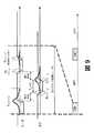
リーダ11は、アンテナ111を介してタグ12にUWBパルス信号を伝送する(S1)。飛行時間(TOF)期間後、伝搬損によって弱められたパルス信号は、タグ12のアンテナ121に達する(S2)。伝送パルス信号が、タグの超再生発振器123へのクエンチ信号の供給に対応するタイムスロットに、すなわちタグ12のアクティブな受信タイムスロット中に受信されると、超再生期間またはクエンチ期間Tq中、発振器123の発振が、タグ受信機によって検出可能なレベルまで増幅されるS3。超再生期間Tqによって、超再生ゲインによって達成された経路損失補償により発振信号を再生することができる。クエンチ信号の供給と入来パルスの受信との間の最適な同期は、tsyncにおいて入来パルスのピーク包絡線が、クエンチ信号によって制御される、発振器の減衰率が図8(iv)に示すように負になるときに対応することを示す。タグ12の入力部に入来パルス信号が受信されない場合、いずれにしても雑音により発振が開始される。しかしながら、結果として得られる、達成可能な発振の振幅は、クエンチ信号の初めに入来パルス信号がある場合よりも遙かに(少なくとも1桁)小さい。リーダ11からの入来パルス信号と、タグ12の超再生発振器123へのクエンチ信号の適用との間のタイミングが正しく同期されると、超再生発振器123において生じた発振は、図8(v)に示すパルス信号に似た検出可能な振幅になる。The
発振ピークのタイミングを、クエンチ信号のパラメータを調整することによって微調整することができる。クエンチ信号の振幅および持続期間の双方により、発振の振幅を微調整することができる。 The timing of the oscillation peak can be fine-tuned by adjusting the quench signal parameters. The oscillation amplitude can be fine-tuned by both the amplitude and duration of the quench signal.
図5Aに示すRFIDタグ回路120のアーキテクチャでは、発振器123をアンテナ121に直接結合している。その結果、発振器123全体に生じた発振をアンテナ121によって直接再放射することができるS4。 In the
発振パルスのリークまたは反射は、再生受信機の典型的な特徴であり、従来技術とは対照的に、本発明のこの実施形態の方法で効果的に使用される。この現象は、反射信号が入来信号自体に干渉するため、伝統的に超再生狭帯域システムにおける問題として見なされている。これは、狭帯域による解決法で使用される固有の連続波形によるものである。しかしながらこれは、UWB通信においては当てはまらない。なぜなら、2つの信号は、時間的に離れており、かつパルス持続期間が短いことから、重なり合わないためである。これにより、従来技術の狭帯域超再生アーキテクチャに必要とされる、アンテナと発振器との間の、電力を多く必要とする低雑音増幅器(LNA)ステージを排除することが可能となる。 Oscillation pulse leakage or reflection is a typical feature of regenerative receivers and, in contrast to the prior art, is effectively used in the method of this embodiment of the invention. This phenomenon has traditionally been viewed as a problem in super-regenerative narrowband systems because the reflected signal interferes with the incoming signal itself. This is due to the inherent continuous waveform used in the narrowband solution. However, this is not true for UWB communications. This is because the two signals do not overlap because they are separated in time and the pulse duration is short. This makes it possible to eliminate the power-intensive low noise amplifier (LNA) stage between the antenna and the oscillator, which is required for the prior art narrow band super regenerative architecture.
入来RFパルス信号と反射RF信号との間の時間遅延を、クエンチ信号の持続時間(Tq)を微調整することにより、延長することができる。従って、クエンチ信号の持続時間を、入来RFパルス信号と、タグから伝送された反射信号との間の時間差が、リーダ側における反射信号の検出に好適となるように選択することができる。図8(v)に示すように、アンテナ121と超再生発振器123との間を適切に絶縁分離することなく、発振器122によって生じたパルス信号を、アンテナ121によって放射して、クエンチ信号の持続時間である時間Tq後にピーク値が発生するようにする。本発明の一部の実施形態では、必要な場合には、反射信号を発生後に、好適な増幅器を用いて増幅してもよい。本実施形態のもののようなパッシブ大容量メモリタグでは、増幅に実現可能な値は、2デシベルの規模のものである。 The time delay between the incoming RF pulse signal and the reflected RF signal can be extended by fine tuning the quench signal duration (Tq). Accordingly, the duration of the quench signal can be selected such that the time difference between the incoming RF pulse signal and the reflected signal transmitted from the tag is suitable for detection of the reflected signal on the reader side. As shown in FIG. 8 (v), the pulse signal generated by the
飛行時間(TOF)後、タグ12からの反射パルス信号はリーダ11のアンテナ111に達しS5、そこで、反射パルス信号はリーダによって検出される。反射信号に得られた振幅を検出することによって、リーダ11は、タグ12に関する情報を得ることができる。 After the time of flight (TOF), the reflected pulse signal from the
この実施形態による方法の背後にある主な意図は、擬似ランダム化パルスシーケンスの位相同期における超再生受信機の固有の特性を利用することにある。この方法は、タグ装置12からリーダ11によって伝送されたパルスの反射に基づく。リーダの観点では、リーダからの初期伝送パルスの伝送と、反射信号のリーダにおける受信との間の時間差が妥当であるように、反射を好適に遅延させる。リーダからの伝送パルスのタイミングとタグにおける検出のタイミングとが正しく合致したときにのみ、反射は発生する。タグから得られる反射を、リーダによって検出することもできる。システムの両側で検出されたこの瞬間をさらに、装置間の同期通信にタイムスタンプとして使用することができる。当然ながら、場合によっては、リーダとタグとの間の第1の合致した反射に関して追加的な検証フェーズが必要になることもあるが、この方法は、いずれの場合も、インパルスUWB送受信機の同期に伝統的に使用された従来の同期方法よりも迅速であるおよび/または単純である。 The main intention behind the method according to this embodiment is to take advantage of the inherent characteristics of the super regenerative receiver in the phase synchronization of the pseudo-randomized pulse sequence. This method is based on the reflection of pulses transmitted by the
本発明の本実施形態では、リーダ回路110はタグ12のタグ回路120に類似した超再生発振器に基づいている。リーダにおける反射パルスの検出は、超再生受信機回路における検出パルスの発生によって達成される。しかしながら、本発明の一部の実施形態では、リーダは、リーダからタグへの反射を利用するように機能しなくてもよい。従って、そのような場合、不要な反射信号がリーダからタグへ伝送されるのを回避するために、アンテナとリーダの発振器との間がより良好に絶縁分離されていてもよい。加えて、リーダ11の電力源はタグ12の電力源ほど制限されていないため、本発明の別の実施形態では、リーダに、より良好な性能を有するより複雑な送受信機を実装することが可能である。 In the present embodiment of the invention, the
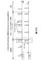
図9にリーダ11とタグ12との間の通信の全体的なタイミングを示し、ここで、破線で示す時間帯Txは、パルス信号の伝送時間を表し、かつ破線で示す時間帯Rxは、信号の受信時間を表す。リーダからの伝送パルス信号の受信に応答して、タグ12の超再生発振器123においてタグ反射パルス信号が発生し、かつタグ12からの反射パルス信号の検出に応答して、リーダ11の超再生発振器においてリーダ反射パルス信号が発生する。本発明のこの実施形態では、リーダでは伝送パルス信号を伝送用に発生させるため、リーダ11のデューティサイクルはタグ12のデューティサイクルよりも(2倍超)長い。本発明のこの実施形態では、リーダ11において超再生受信機を使用して反射パルス信号を検出するため、入来反射パルス信号を増幅する必要があり、それは伝送と同程度長くなり得る。さらに、リーダは、リーダからタグへ、そしてリーダへの信号の双方向の飛行時間を考慮する必要がある。しかしながら、高速RFIDシステムにありそうな短距離では、一方の送受信機から他方の送受信機への信号の飛行時間は、数百ピコ秒程度である。30cmの距離において、自由空間の飛行時間はほぼ1nsである(双方向のTOFは2ns)。しかしながら、本発明のこの実施形態による方法が、例えばUWBポジショニングシステムなどの、送受信機間の距離がより長い低データ転送速度システムに適用される場合、伝搬に必要な時間は著しく長くなる。 FIG. 9 shows the overall timing of communication between the
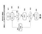
RFIDシステムのリーダとタグとの間の完全な同期手順における本発明の少なくとも一実施形態による位相同期方法の実装例を、図10および図11を参照して説明する。 An example implementation of a phase synchronization method according to at least one embodiment of the invention in a complete synchronization procedure between a reader and a tag of an RFID system will be described with reference to FIGS.
完全な同期手順を、4つ以上のステップに分けることができる:周波数同期(S21)、同期パルスの検索(S22)および同期の検証(S23)。検証フェーズ後、実データ転送または通信を実行することができる(S24)。 The complete synchronization procedure can be divided into four or more steps: frequency synchronization (S21), synchronization pulse search (S22) and synchronization verification (S23). After the verification phase, actual data transfer or communication can be executed (S24).
同期手順または少なくとも検証フェーズを、通常一定期間後に繰り返して、同期が依然として正しいことを保証することができる。 The synchronization procedure or at least the verification phase can usually be repeated after a period of time to ensure that the synchronization is still correct.
周波数同期のステップ(S21)に使用され得る方法の例は、相互クロック基準を引き出すために装置間で共有された共通の連続波長(CW)信号に基づく方法であるか、またはリーダおよびタグの双方ともが、十分正確でありかつ1通信パケットの通信中に周波数に著しいドリフトが生じない周波数合成器を有する代替的な方法である。高ビットレートRFIDは、第1の代替方法に基づいたものとすることができる。 Examples of methods that can be used for the frequency synchronization step (S21) are methods based on a common continuous wavelength (CW) signal shared between devices to derive a mutual clock reference, or both reader and tag Both are alternative methods having a frequency synthesizer that is sufficiently accurate and does not cause significant drift in frequency during the communication of one communication packet. High bit rate RFID may be based on a first alternative method.
周波数同期ステップ(S21)後、リーダおよびタグのクロックは、同じ周波数で動く。しかしながら、このステージでは、リーダおよびタグは、それらの相手方の装置の位相は分かっていない状態にある。次いで、装置の一方、例えばリーダが、一連の伝送パルスTxを伝送することによって位相同期検索S22の伝送を始める。短い周期のパルスシーケンスの伝送はUWB規制に従って実行可能ではないため、同期シーケンスを例えば、十分に平滑な透過スペクトルをもたらす時間ホッピングシーケンスとし得る。各伝送パルスTx後に、上述のように反射パルス信号が存在することをリーダが検証できるように、リーダの送受信機を配置する。タグ側では、クエンチ信号によって、それ自体の予め定められた同期シーケンスに従って超再生受信機をアクティブにする。換言すれば、タグのクエンチ信号が超再生機発振器の減衰率を制御し、それにより、予め定められたシーケンスに従って発振器を不安定な性質にすることができる。符号シーケンスを、例えば電源の利用可能性、フィールド内でのタグの数、干渉の問題などの環境の状況に依存して最適にすることができる。 After the frequency synchronization step (S21), the reader and tag clocks run at the same frequency. However, at this stage, the reader and tag are in a state where the phase of their counterpart device is unknown. Then, one of the devices, for example the reader, starts transmitting the phase synchronization search S22 by transmitting a series of transmission pulses Tx. Since transmission of short-period pulse sequences is not feasible according to UWB regulations, the synchronization sequence can be, for example, a time hopping sequence that results in a sufficiently smooth transmission spectrum. After each transmission pulse Tx, the reader's transceiver is arranged so that the reader can verify the presence of the reflected pulse signal as described above. On the tag side, the quench signal activates the super regenerative receiver according to its own predetermined synchronization sequence. In other words, the tag quench signal controls the attenuation factor of the super regenerator oscillator, thereby making the oscillator unstable in accordance with a predetermined sequence. The code sequence can be optimized depending on the circumstances of the environment, for example the availability of the power supply, the number of tags in the field, the interference problem.
タグにおける受信機のデューティサイクルは短いが、受信シーケンスを最適にして、タグのアクティブな受信期間の少なくとも1つが、位相同期検索中に高確率でリーダからの入来伝送信号と合致するようにするS22。タグ12のクエンチ期間(Tq)間の分離を一定とすることができ、それは、リーダ11による伝送とタグ12による受信との間の合致を迅速化する助けとなり得る。最適化された擬似ランダム符号を、S22中にタグ12のクエンチシーケンスに使用してもよい。リーダは、1パルスに対するリーダとタグとの間の正確なタイミングを示すタグからの反射信号を検出するまで、または同期処理の状態機械が、予め定められた計数値の終りまでカウントするまで、パルス信号を伝送し続ける。リーダからの伝送パルス信号と、タグにおける受信機のクエンチ期間のタイミングとが合致する場合、入来伝送パルスが、反射信号の形態でタグ12から反射されて戻り、リーダ11によって検出される。クエンチ期間中、検出レベルを超えるために、入来伝送パルスに応答して、タグ12において超再生発振器123によって発生された信号が十分に高い振幅に達するときにのみ、検出可能な反射パルス信号が発生する。伝送パルスTxとタグのクエンチ期間との間の正確なタイミングが、両装置によってすぐに検出されるため、第1の合致が位相同期検索S22で発生した後、位相同期の検証S23を開始できる。 Although the receiver's duty cycle at the tag is short, the receive sequence is optimized so that at least one of the tag's active receive periods matches the incoming transmission signal from the reader with high probability during the phase synchronization search. S22. The separation between the quench periods (Tq) of the
位相同期検証フェーズS23では、リーダ11からの伝送パルス信号と、タグ発振器123のクエンチ信号との間のタイミングの微調整を実行することができ、同期シーケンスの相関関係を保証する。同期符号の時間ホッピングシーケンスは、リーダおよびタグの双方がシーケンスに従うことができるように予め定められている。上述のように、周波数同期を他の手段によって実施することもでき、そのため、シーケンスの開始が反射パルス信号の第1の検出によって確認された後に、両装置が、十分な正確さをもって時間ホッピングシーケンスに従うことができることを前提としている。第1の反射が意図されたものでない場合、例えば、干渉のためにリーダで反射信号が検出される場合、時間ホッピングシーケンスの残りの反射の発生はなさそうであり、リーダはステップS22の同期検索に戻ってもよい。相関関係が十分に良好でない場合または検証フェーズS23中に同期が失われる場合、両装置はステップS22に戻って、もう一度やり直してもよい。 In the phase synchronization verification phase S23, fine adjustment of the timing between the transmission pulse signal from the
十分な期間後、すなわち十分に長い同期シーケンス後、フォールスアラームの可能性は十分に小さい。そこで、リーダとタグとの間の同期は、十分良好であると見なされ、通信を開始することができる。通信フェーズでは、反射パルス信号を検出する必要はない。しかしながら、本発明の一部の実施形態では、反射信号を使用して、誤り検査または誤り訂正のために確認応答情報を転送することができる。同期検証ステップS22を一定期間後に繰り返して、同期が依然として十分良好であることを保証することができる。通信フェーズS23中に接続が途切れる場合には、両装置は再び位相同期検索フェーズS22から始めるか、または同様に周波数同期が失われる場合には周波数同期フェーズS21から始めることができる。 After a sufficient period of time, i.e. after a sufficiently long synchronization sequence, the possibility of a false alarm is sufficiently small. Thus, the synchronization between the reader and the tag is considered sufficiently good and communication can be started. In the communication phase, it is not necessary to detect the reflected pulse signal. However, in some embodiments of the invention, the reflected signal can be used to transfer acknowledgment information for error checking or error correction. The synchronization verification step S22 can be repeated after a certain period to ensure that the synchronization is still good enough. If the connection is interrupted during the communication phase S23, both devices can start again from the phase synchronization search phase S22, or similarly from the frequency synchronization phase S21 if frequency synchronization is lost.
図12を参照すると、同期の微調整を、1つ以上の検出反射信号、および場合によっては各検出反射信号を使用して、リーダによって位相同期の検証ステージにおいて行うことができる。これは、リーダの超再生受信機において、得られる発振のピーク値を測定することにより行われる。位相同期検索期間S22後、リーダおよび1つまたは複数のタグは位相同期検証期間S23において同期手順を続けることができ、次いで、パルスがリーダから伝送されて、予め定められたシーケンスに従ってタグから反射される。リーダとタグとの間のタイミングが最適でない場合、タグ12における内部発振のピーク値は、可能な最適なタイミングで達成される場合よりも低くなる。リーダ11の反射パルスによってトリガされた内部発振のピーク値を測定することができ、それに応じて、同期パルスのタイミングを、タグのタイミングにより良好に合致するように微調整することができる。 Referring to FIG. 12, fine tuning of the synchronization can be performed by the reader in the phase synchronization verification stage using one or more detected reflected signals and possibly each detected reflected signal. This is done by measuring the peak value of the oscillation obtained in the reader super reproduction receiver. After the phase synchronization search period S22, the reader and one or more tags can continue the synchronization procedure in the phase synchronization verification period S23, and then a pulse is transmitted from the reader and reflected from the tag according to a predetermined sequence. The If the timing between the reader and the tag is not optimal, the peak value of internal oscillation at the
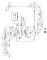
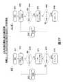
図13に、リーダの観点から本発明の一部の実施形態による同期手順全体をより詳細に示し、および図14に、対応して、タグの観点から同じ手順を示す。 FIG. 13 shows the overall synchronization procedure according to some embodiments of the present invention in more detail from the reader's perspective, and FIG. 14 correspondingly shows the same procedure from the tag's perspective.
図13を参照すると、リーダ11は、同期コマンドを待ちのアイドル状態S31から開始される。同期コマンドが、リーダが関連しているシステムの上位層によって与えられるとすぐにS32、例えばUHF CW伝送を開始することによって、周波数同期から始まって同期処理が開始されるS33。開始期間が満了すると、システムは位相同期検索ステージS33を続けて、予め定められた時間ホッピングスケジュールに従って同期パルスを伝送し始めるS33a。位相同期検索フェーズは、リーダが応答を検出するまでS33b、または特定のカウンタがゼロをカウントするまでS33c続く。このフェーズ中にカウンタがゼロをカウントする場合、タグが見つからなかったステータスがシステムの上位層に報告され、リーダはアイドル状態S31に戻る。あるいは、リーダが反射信号を検出する場合、リーダは位相同期検証フェーズS34を続け、反射間の相関関係、および実行される場合には、タイミング微調整手順S35を開始する。このフェーズ中に反射信号が失われるかまたは検出されない場合、リーダは位相同期検索ステージS33Aに戻ってもよい。同期シーケンス全体が十分に高い相関関係で検出される場合、システムは同期通信フェーズに入って、「同期成立」フラグを有するステータスを上位層に戻しS36、かつ対象のタグに対して実データのやりとりの転送を始めてもよいS37。 Referring to FIG. 13, the
図14を参照すると、タグは、対応してアイドル状態S41から開始される。タグの電力レベルが十分に高くなるとすぐにS42、タグは周波数同期手順を実行しS43、UHF CW信号でロックし得る。次いでタグは位相同期検索フェーズに入り、予め定められたスケジュールに従って発振器の制御信号のクエンチを開始するS44。タグは、パルスを検出するまでS45、または時間ホッピングシーケンスの終了をカウントするまでS46続く。第1のシーケンス後、タグは新しいシーケンスに入るか、または最初の1つの初めから継続する(クエンチシーケンスのパルス繰り返し率もまた一定とし得る)。位相同期検索フェーズ中にタグがパルスを検出すると、タグは検証フェーズに直接入るS47。同期パルスのスケジュールに従って検証フェーズが実行され、およびまた、相関関係が十分に高い場合、システムは実際の同期データ転送状態に入ってもよいS48。 Referring to FIG. 14, the tag is correspondingly started from the idle state S41. As soon as the power level of the tag is high enough, S42, the tag can perform a frequency synchronization procedure and lock with S43, UHF CW signal. The tag then enters the phase synchronization search phase and initiates quenching of the oscillator control signal according to a predetermined schedule S44. The tag continues S45 until a pulse is detected, or S46 until the end of the time hopping sequence is counted. After the first sequence, the tag enters a new sequence or continues from the beginning of the first one (the pulse repetition rate of the quench sequence may also be constant). If the tag detects a pulse during the phase synchronization search phase, the tag enters the verification phase directly S47. If the verification phase is performed according to the schedule of sync pulses and the correlation is high enough, the system may enter the actual sync data transfer state S48.
従来技術の方法と比べると、本発明による方法は、UWBインパルス無線通信における同期を確認する即時確認応答を提供する。確認応答情報に基づいて、1つの同期シーケンスの長さを単一の伝送パルスともし得るために、UWB通信において伝統的に使用された方法と比較して同期処理を加速させることができる。 Compared to the prior art method, the method according to the present invention provides an immediate confirmation response confirming synchronization in UWB impulse radio communication. Based on the acknowledgment information, the synchronization process can be accelerated compared to methods traditionally used in UWB communications because the length of one synchronization sequence can also be a single transmission pulse.
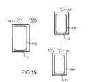
本発明の一部の実施形態では、リーダの通信距離またはカバレージエリア内の複数のタグの存在を支援可能とするためにRFIDシステムが必要とされ得ることを理解されたい。そのような場合では、同期スキームは、多重アクセスをサポートすることができる必要がある。本発明の第1の実施形態による方法を、3つ以上のタグのアクセスをサポートするように簡単に拡張することができる。図15および図16に、2つのタグ12および13がリーダ11の近傍にある場合の本発明の第2の実施形態による方法の使用を示す。タグ13は、上述のようにタグ12と同様に動作する。 It should be understood that in some embodiments of the present invention, an RFID system may be required to be able to support the presence of multiple tags within a reader's communication range or coverage area. In such cases, the synchronization scheme needs to be able to support multiple access. The method according to the first embodiment of the invention can easily be extended to support access of more than two tags. 15 and 16 illustrate the use of the method according to the second embodiment of the present invention when two
位相同期検索ステップS52では、タグ12および13の双方とも、リーダ11によって伝送された伝送パルスの検索シーケンスを受け取る。タグ12および13の受け取り期間は位相同期されないであろう。タグの受け取り期間の位相差は、公知の方法を使用することによって達成されてもよい−受け取り期間の選択は、例えばある程度のランダム処理を含み、および一定期間後に期間もまた変化してもよい。タグ受信活動のデューティサイクルに依存して、複数のタグが、重なり合うことなく同時にアクティブになり得る。タグのうちの1つ、例えばタグ13のアクティブな受信期間が、リーダ11からの伝送と合致するとすぐに、リーダ11およびタグ13は位相同期の検証ステージS53に入る。タグ13とリーダ11との間の位相同期の検証ステージS53中、タグ12が入来パルスを検出して反射パルスを伝送すると、タイミングが間違っていると推測される。なぜなら、タグ13およびリーダ11が既に、予め定められた時間ホッピングシーケンスに従って位相同期の検証ステージに進んでいるためである−すなわちリーダ11は、タグ12とは異なるアクティブな受信期間を有するタグ13と順々に動く必要がある。タグ12は、タグ13またはリーダ11によって伝送されたパルスを検出し得る。それらパルスを、図16のタグ12の時間軸で第1および第2の円印によって示す。しかしながら、タグ12は、期間T1後、別のどのパルスも検出する必要がないため、誤った検出または意図的でない不一致後に位相同期検索ステージS52に戻る。 In the phase synchronization search step S52, both the
本発明の一部の実施形態では、通信システムはまた、一定回数の散発性の誤った検出があった後にタグが反射メカニズムを止めるようにするいわゆるバックオフメカニズムを含み得る。これは、タグ13とリーダ11との間の通信における干渉を低減する役割を果たす。さらに、タグ12は、リーダ11がすでにタグ12との位相同期を達成した場合にはバックオフステージに入ってもよいが、リーダ11はスキャンモードを続けて、通信距離内の全てのタグを1つずつ検出しようとする。 In some embodiments of the present invention, the communication system may also include a so-called back-off mechanism that allows the tag to stop the reflection mechanism after a certain number of sporadic false detections. This serves to reduce interference in communication between the
本発明の一部の実施形態では、第1の同期処理後であってかつ第1のタグが認識された後、リーダは、タグを「応答しない」状態に設定する。これは、別のタグがリーダによって見つけられる可能性を高くするための一定期間中は、タグが同期パルスに応答しないことを意味する。 In some embodiments of the invention, after the first synchronization process and after the first tag is recognized, the reader sets the tag to a “not responding” state. This means that the tag does not respond to the sync pulse for a period of time to increase the likelihood that another tag will be found by the reader.
同期通信フェーズS54中、タグ12に起因する衝突の回数を、例えば、同期通信フェーズに新しい同期ワードを、位相同期検証フェーズに使用されたデフォルトのワードの代わりに選択することによって、最小限することができる。他の装置は、位相検証フェーズで使用されたシーケンスから開始してもよいが、タグ13は、少なくとも一定期間、リーダ11によって規定されたシーケンスから開始する。 Minimizing the number of collisions due to the
UWB通信に超再生アーキテクチャを使用することは、狭帯域解決法のパルス反射の弱点を同期に好都合に利用できるため、本発明の上述の実施形態では魅力がある。それにより、提案された方法は、そのような受信機をインパルスUWB通信に使用することを可能にし、かつそれを改善する。 Using a super-regenerative architecture for UWB communications is attractive in the above-described embodiments of the present invention because the weakness of the narrowband solution's pulse reflection can be exploited for synchronization. Thereby, the proposed method enables and improves such a receiver to be used for impulse UWB communications.
しかしながら本発明による同期方法は、超再生送受信機に限定されず、代替的な回路アーキテクチャの別の実施形態を使用してもよいことを理解されたい。 However, it should be understood that the synchronization method according to the present invention is not limited to super regenerative transceivers and may use alternative embodiments of alternative circuit architectures.
図17に、代替的な回路アーキテクチャをタグに使用する本発明の別の実施形態を示す。本発明の別の実施形態による回路220は、受信機アンテナ221に結合された低雑音増幅器LNA222と、LNA222に結合されたパルス復調器223と、制御論理224と、パルス整形モジュール225と、送信機アンテナ227に結合された増幅器226とを含む。装置のアクティブな受信期間を制御論理によって規定できる。 FIG. 17 illustrates another embodiment of the present invention that uses an alternative circuit architecture for the tag.
一定の時間間隔で、パルス復調器223はアンテナ221において入力パルスをチェックする。入力パルスが検出される場合、パルス整形モジュール225が制御論理224の制御下でパルスを発生して、パルス増幅器226および送信アンテナ227を介してパルスをリーダ装置に伝送する。次いで、パルスはリーダによって検出されて、リーダとタグのアクティブな受信期間との間の同期が正しいことを示す。 At regular time intervals, the
代替的な回路はまた、リーダにおいても実装される。 Alternative circuitry is also implemented in the reader.
本発明の代替的な実施形態においては、例えばアンテナスイッチを有する単一のアンテナを、先の実施形態の2つのアンテナ221および227と好都合に置き換えることができることを理解されたい。 It should be understood that in alternative embodiments of the present invention, a single antenna, for example with an antenna switch, can be advantageously replaced with the two
当業者であれば、例示のためにRFIDシステムを参照して位相同期の原理を説明したが、本方法を、UWB通信システムにおける他のタイプの送受信機の同期に使用し得ることも理解するであろう。例えば、本発明による方法を用いて、ビーコンの電力消費を最小限に保つ必要のあるUWBポジショニング装置間の同期を達成し得る。同期後、例えば、伝送信号および/または反射信号の飛行時間(TOF)に基づいた距離推定を実行することができる。そのようなシステムでは、必要なデータ転送速度はより低速であり、かつ通信範囲はより広範である。 Those skilled in the art will understand the principle of phase synchronization with reference to an RFID system for illustration, but it will also be appreciated that the method can be used to synchronize other types of transceivers in a UWB communication system. I will. For example, the method according to the invention may be used to achieve synchronization between UWB positioning devices that need to keep beacon power consumption to a minimum. After synchronization, distance estimation based on, for example, the time of flight (TOF) of the transmitted signal and / or reflected signal can be performed. In such a system, the required data transfer rate is lower and the communication range is wider.
本発明の別の実施形態では、タグにおけるデータ内容の暗号化またはロッキングを、リーダとタグとの間の相互に合意した時間ホッピングシーケンスに基づいて行うことができる。次いで、通常の同期手順後にこの時間ホッピングシーケンスを用いて、プライベートデータの伝送中にセキュリティを提供することができる。リーダが時間ホッピングシーケンスを知らない場合には、つまり、リーダがタグのデータへのアクセス許可を有しない場合には、リーダは、シーケンスが十分に長いと非常に高い確率でタグとの同期を解く。 In another embodiment of the invention, the encryption or locking of the data content at the tag can be based on a mutually agreed time hopping sequence between the reader and the tag. This time hopping sequence can then be used after the normal synchronization procedure to provide security during the transmission of private data. If the reader does not know the time hopping sequence, i.e. if the reader does not have permission to access the tag's data, the reader will unsynchronize with the tag with a very high probability if the sequence is long enough. .
反射の原理を両方向に用いることができることを理解されたい。従って、タグはまた、データがタグからリーダに転送されるときにリーダからの反射を検出することも可能である。これは、データをタグからリーダに転送するときには、タグが自動的にリーダから確認応答情報を得るため、現実的である。類似の方法を適用することによって誤りを検出して訂正してもよい。 It should be understood that the principle of reflection can be used in both directions. Thus, the tag can also detect reflections from the reader as data is transferred from the tag to the reader. This is realistic because when the data is transferred from the tag to the reader, the tag automatically obtains acknowledgment information from the reader. An error may be detected and corrected by applying a similar method.
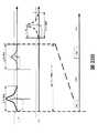
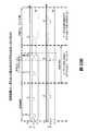
リーダによって伝送されたRFパルスもまた、カバレージエリア内で他のパッシブ構造によって反射されることがあるため、本発明の一部の実施形態では、シーケンス同期の検証期間中にテストパルスを使用することによって伝搬環境の測定を行うことが好都合であろう。従って、リーダが第1の反射パルスを検出して、予め定められた時間ホッピングスキームに従って同期シーケンスの伝送を開始した後、タグの検出シーケンスと同期している必要のないいくつかの追加的なパルスも伝送し得る。このことは有利なことであり、その理由は、追加的なパルスの一部またはすべてが反射してリーダに戻される場合、パルスが反射性材料などから意図せず反射されることを示しているからである。伝送されたテストパルスに対する反射/応答がない場合またはリーダによって検出することができる反射が非常に弱い場合、リーダは、実装置と同期していると結論付けてよい。図18にその手順を示す。図18では、追加的なテストパルスおよび対応する反射信号を破線で示し、および同期伝送パルスおよび関連の反射信号を実線で示す。追加的なテストパルスは、位相シーケンス同期の検証期間中に伝送される。原理上、位相同期検索フェーズにおいてもテスト測定は可能であるが、その場合、タグがパルスに応答しているかどうかを検証することは不可能であり得る。位相同期検証期間では、タグは、同期スキームに従って主伝送パルスに応答する必要がある。同期スキームによれば、タグは追加的なテストパルスに応答するべきではない。しかしながら、強すぎる反射が発生して、リーダに検出されると、リーダの近傍に反射層があり、通信が妨げられているという結論になり得る。他方で、一定期間後であってかつ双方向の飛行時間直後ではないときに正しい反射が発生するようにタグのクエンチ信号を規定してもよい。さらに、タグは上述のように反射を著しく増幅する必要があり、それゆえ、正しい反射は、パッシブ物体からのファントム反射よりもはるかに強力である必要がある。 Because some RF pulses transmitted by the reader may also be reflected by other passive structures within the coverage area, some embodiments of the invention use test pulses during the sequence synchronization verification period. It may be convenient to make a measurement of the propagation environment. Thus, after the reader detects the first reflected pulse and initiates transmission of the synchronization sequence according to a predetermined time hopping scheme, several additional pulses that need not be synchronized with the tag detection sequence Can also be transmitted. This is advantageous because the reason is that if some or all of the additional pulses are reflected back to the reader, the pulses are unintentionally reflected from reflective material etc. Because. If there is no reflection / response to the transmitted test pulse or if the reflection that can be detected by the reader is very weak, it may be concluded that the reader is synchronized with the real device. FIG. 18 shows the procedure. In FIG. 18, additional test pulses and corresponding reflected signals are indicated by dashed lines, and synchronous transmission pulses and associated reflected signals are indicated by solid lines. Additional test pulses are transmitted during the phase sequence synchronization verification period. In principle, test measurements are also possible in the phase synchronization search phase, but in that case it may not be possible to verify whether the tag is responding to a pulse. In the phase synchronization verification period, the tag needs to respond to the main transmission pulse according to the synchronization scheme. According to the synchronization scheme, the tag should not respond to additional test pulses. However, if a too strong reflection occurs and is detected by the reader, it can be concluded that there is a reflective layer in the vicinity of the reader, preventing communication. On the other hand, the tag quench signal may be defined so that the correct reflection occurs after a certain period and not just after the two-way flight time. In addition, the tag needs to significantly amplify the reflection as described above, so the correct reflection needs to be much stronger than the phantom reflection from a passive object.
本発明の別の実施形態では、反射パルスのタイミングに対する厳しい条件を使用して、通信距離を一定の限界よりも下にすることができる。これは、短距離通信における秘密性を高めるため、すなわち、規制限度を上回る高電力レベルを使用しかつ意図されたよりも長い通信距離を有する「スパイ」装置で遠隔点から大容量メモリタグを読み取られることを回避するために必要である。例えば、タグがリーダからの反射を検出する、またはその逆を行う期間を使用して、応答時間が十分に短いことを検出し、かつ例えば秘密性の保護限界よりも長距離離れた点からの反射の発生を回避することができる。さらに、反射パルス信号に基づいた距離測定を、接続セットアッププロトコルに有利に使用して、システムの論理的な有用性を改善することができる。2つ以上のタグがリーダの読み取り範囲内に存在する場合には、見つかったタグのリストのうち最も近いタグがまずアクセスされるかまたはまずリストされるように通信プロトコルを実施して、それがリーダのユーザインターフェースに示されるようにしてもよい。 In another embodiment of the present invention, stringent conditions on the timing of the reflected pulses can be used to reduce the communication distance below a certain limit. This increases the secrecy in short-range communications, i.e. reads high capacity memory tags from a remote point with "spy" devices that use high power levels above regulatory limits and have longer communication distances than intended It is necessary to avoid that. For example, a period in which the tag detects reflection from the reader or vice versa is used to detect that the response time is sufficiently short, and for example from a point far away from the confidentiality protection limit. The occurrence of reflection can be avoided. In addition, distance measurements based on reflected pulse signals can be advantageously used in connection setup protocols to improve the logical usefulness of the system. If more than one tag is present in the reader's reading range, the communication protocol is implemented so that the closest tag in the list of found tags is accessed or listed first, It may be shown on the user interface of the reader.
本発明の一部の実施形態では、例えば、十分な電力源を有する装置において複数の並列超再生受信機を使用して、同期処理を加速することができることを理解されたい。検出間隔は超再生受信機間でインターリーブされ得る。 It should be understood that in some embodiments of the invention, multiple parallel super-regenerative receivers can be used, for example, in a device with sufficient power sources to accelerate the synchronization process. The detection interval can be interleaved between super regenerative receivers.
電力レベルがより高い電力消費を許す場合には、超再生受信機のデューティサイクルを同期フェーズにおいて増大させて同期を迅速化することができることにも理解されたい。 It should also be understood that if the power level allows higher power consumption, the super regenerative receiver duty cycle can be increased in the synchronization phase to speed up the synchronization.
上述の実施形態では同期シーケンスはリーダで開始されるが、本発明の別の実施形態では同期シーケンスをリーダまたはタグのいずれによって開始してもよいことを理解されたい。 In the embodiments described above, the synchronization sequence is initiated at the reader, but it should be understood that in other embodiments of the invention, the synchronization sequence may be initiated by either the reader or the tag.
当業者はまた、位相同期に関して上述した方法と同じ反射方法を、装置間の実データ転送に利用することが可能であることを理解するであろう。情報を、例えば同期を確立した後にタグにおいて反射パルスを可能にしたり省略したりすることによって、反射パルスに含めることができる。しかしながら、同期が十分良好である場合には、データ転送中、反射は連続的である必要はない。不要な反射検出によってシステム全体の電力消費を増大させ、それゆえ、実データが転送されるときにデータを一方向のみに伝送するのにより効率的となり得る。さらに、この方法はまた確認応答キャラクタおよび誤り訂正に使用することもできる。 One skilled in the art will also appreciate that the same reflection method described above with respect to phase synchronization can be utilized for actual data transfer between devices. Information can be included in the reflected pulse, for example by enabling or omitting the reflected pulse in the tag after establishing synchronization. However, if the synchronization is good enough, the reflection need not be continuous during the data transfer. Unnecessary reflection detection increases the power consumption of the entire system and can therefore be more efficient in transmitting data in only one direction when real data is transferred. In addition, this method can also be used for acknowledgment characters and error correction.
インパルスUWB RFIDシステムにおいて超再生送受信機の使用に関連して起こりうる問題は、アンテナへの入力部における雑音の入力または干渉から生じたタグによる反射信号の伝送である−そのような場合を以下、ゼロの検出と呼ぶ(すなわち受信機のアンテナにおいて意図的な伝送信号の入来がない)。図19に示すように、論理「0」の検出(すなわちタグのアンテナ入力部において雑音のみ)が、タグの超再生発振器に有意義なパルスを発生させる場合がある。好ましくは発振器とアンテナとの間に緩衝増幅器を使用しないため、反射信号はその後アンテナによって伝送され得る。 A possible problem associated with the use of a super regenerative transceiver in an impulse UWB RFID system is the transmission of a reflected signal by a tag resulting from noise input or interference at the input to the antenna-such a case is described below. Called zero detection (ie no intentional incoming transmission at the receiver antenna). As shown in FIG. 19, detection of logic “0” (that is, only noise at the antenna input portion of the tag) may cause a significant pulse to be generated in the super reproduction oscillator of the tag. Since preferably no buffer amplifier is used between the oscillator and the antenna, the reflected signal can then be transmitted by the antenna.
ピーク値「1」、すなわち意図的な入来伝送パルスが検出されていることと、ピーク値「0」、すなわち雑音のみが検出されていることとの間の推定比を、場合によっては約5〜10とし得る。従って、発生したパルスのピーク値は、「1」のときには、「0」のときよりも5〜10倍大きい必要がある。超再生受信機では、単純な包絡線検波器の出力部において結果的に生じる発振の振幅を観察することによって、受信した「1」と受信した「0」との間の差を得ることができる。上述のように、受信タイミングの最も重要なポイントは、クエンチ信号によって制御された発振器減衰率のゼロ交差である。ゼロ交差中に入来RFパルスがある場合、検出結果は「1」となるはずである。それ以外は、検出した値は「0」となる。 The estimated ratio between the peak value “1”, i.e. the intentional incoming transmission pulse being detected, and the peak value “0”, i.e. only the noise being detected, is approximately 5 in some cases. -10. Therefore, the peak value of the generated pulse needs to be 5 to 10 times larger at “1” than at “0”. In a super regenerative receiver, the difference between the received “1” and the received “0” can be obtained by observing the amplitude of the resulting oscillation at the output of a simple envelope detector. . As mentioned above, the most important point of reception timing is the zero crossing of the oscillator attenuation factor controlled by the quench signal. If there is an incoming RF pulse during the zero crossing, the detection result should be “1”. Otherwise, the detected value is “0”.
タグからのパルスの反射を可能にしかつタグの電力消費を最小限にするために、発振器とアンテナとの間に緩衝増幅器を使用していないため、ゼロの検出は、発振器に、タグのアンテナから伝送されるパルスを発生させることができる。初期のゴーストパルスに応答してリーダからゴーストパルスが伝送されてもよい。入来「ゼロ」の検出の結果として伝送されたこれらの意図的でない信号を、以下ゴーストパルスと呼ぶ。 Since no buffer amplifier is used between the oscillator and the antenna to allow reflection of the pulse from the tag and to minimize the power consumption of the tag, the detection of zero is from the tag antenna to the oscillator. Transmitted pulses can be generated. A ghost pulse may be transmitted from the reader in response to the initial ghost pulse. These unintentional signals transmitted as a result of incoming “zero” detection are hereinafter referred to as ghost pulses.
そのようなゴーストパルスに起こり得る問題は、タグが、リーダによって発せられたゴーストパルスを、リーダによって伝送された値「1」の意図的なパルスと区別することが困難であることである。この理由は、自由空間の経路損失のために、30cmの範囲内でさえ減衰が、図20に示すように著しく変化することである(例えば、短距離RFID通信において目標とされている7.9GHzにおいて2〜30cmの間で約30dBの減衰)。「0」の検出(雑音)と「1」の検出(意図的な伝送パルス)との間の推定振幅比は、信号対雑音および干渉比に強く依存し、これらは、場合によっては、経路損失が変化することによる振幅変動よりも小さくなり得る。その結果、タグによって受信された2つの異なるパルスの振幅は、その目的が全く異なっても、同じとなり得る:例えば1パルスをリーダからの意図的な伝送パルスとして伝送し(装置間の距離が長い、例えば30cmのとき)、かつ別のパルスを、リーダから意図せずに伝送されたゴーストパルスとし得る(装置間の距離が短い、例えば10cmのとき)。 A possible problem with such ghost pulses is that it is difficult for the tag to distinguish ghost pulses emitted by the reader from intentional pulses of value “1” transmitted by the reader. The reason for this is that due to path loss in free space, even within the 30 cm range, the attenuation varies significantly as shown in FIG. 20 (eg, 7.9 GHz targeted in short range RFID communications). At about 30 dB attenuation between 2 and 30 cm). The estimated amplitude ratio between the detection of “0” (noise) and the detection of “1” (intentional transmission pulse) depends strongly on the signal-to-noise and interference ratio, which in some cases may be path loss. It can be smaller than the amplitude variation due to the change of. As a result, the amplitude of two different pulses received by the tag can be the same, even if their purpose is completely different: for example, one pulse is transmitted as an intentional transmission pulse from the reader (the distance between the devices is long) ,
以下説明する実施形態を、ゴーストパルスに起因して起こり得るいずれの欠点も最小限にするように設計する。 The embodiments described below are designed to minimize any drawbacks that can occur due to ghost pulses.
図21Aに、本発明の少なくとも一実施形態による3つのフェーズ(同期検索、同期シーケンスおよび微調整、および通信)を含む例示的な同期スキーム全体を示す。一番上の時間軸は、リーダの信号を示し、一番下の時間軸はタグの信号を示す。この場合、リーダによって伝送され(破線の囲み)、かつタグによって反射されるパルスの第1の合致を、上手く使用して、装置間の同期通信を検出しかつ開始する。図21Bに、第1の反射期間中のパルスのタイミングを示す拡大図を示す。一番上の時間軸はリーダの信号を示し、中央の時間軸はタグの信号を示し、および一番下の時間軸はデータのデューティサイクルを示す。パルスの第1の合致は、時間的に正確に整列されるので、ゴーストパルスの悪影響は経験されない。 FIG. 21A illustrates an overall exemplary synchronization scheme including three phases (synchronous search, synchronization sequence and fine-tuning, and communication) in accordance with at least one embodiment of the invention. The top time axis shows the reader signal, and the bottom time axis shows the tag signal. In this case, the first match of the pulses transmitted by the reader (dotted box) and reflected by the tag is successfully used to detect and initiate synchronous communication between the devices. FIG. 21B shows an enlarged view showing the timing of the pulses during the first reflection period. The top time axis shows the reader signal, the middle time axis shows the tag signal, and the bottom time axis shows the data duty cycle. Since the first match of the pulse is accurately aligned in time, no ghost pulse adverse effects are experienced.
図22Aに、同期のフォールスアラームがタグで発生する状況を示す。破線の囲みの拡大図を図22Bに示す。図22Bのリーダの時間軸上の第1のパルスは、リーダによって伝送される値「1」の実際のパルスである。図21Bと同様に、伝送パルスの後には、リーダにおいて検出期間が続き、この期間内にリーダにおいて検出パルスが発生される。いずれのタグからも第1の意図的な伝送パルスへの反射信号がないので、リーダにおける発振は、入来「1」パルスを示すために定められた検出閾値を超えない。しかしながら、得られる発振は、リーダによってその後に伝送されるゴーストパルスとして見られ、かつ(リーダからの)ゴーストパルスの伝送が、タグの検出時間に関して正しいときに発生するので、タグによって検出される(装置間にそれ以前の同期は達成されていない)。値「1」の意図的な伝送パルスよりもゴーストパルスの振幅は小さいが、モバイル機器間の距離が変化することで生じる経路損失変動のために、フォールスアラームが発生する。起こり得る問題は、タグが、リーダからの誤った確認応答として入来ゴーストパルスを検出するために、同期手順においてフェーズ2を続ける(あるいはデータ転送を開始する)ことである。これに対し、リーダは、その検出期間中にいかなるRFパルスも検出しなかったため、いかなる状態遷移も行わない。 FIG. 22A shows a situation where a synchronous false alarm occurs on the tag. An enlarged view of the dashed box is shown in FIG. 22B. The first pulse on the time axis of the reader in FIG. 22B is an actual pulse of value “1” transmitted by the reader. Similar to FIG. 21B, the transmission pulse is followed by a detection period in the reader, and a detection pulse is generated in the reader within this period. Since there is no reflected signal from either tag to the first intentional transmission pulse, the oscillation at the reader does not exceed the detection threshold set to indicate an incoming “1” pulse. However, the resulting oscillation is detected by the tag as it appears as a ghost pulse that is subsequently transmitted by the reader and occurs when the transmission of the ghost pulse (from the reader) is correct with respect to the tag detection time ( Previous synchronization between devices has not been achieved). Although the amplitude of the ghost pulse is smaller than the intentional transmission pulse having the value “1”, a false alarm is generated due to a path loss variation caused by a change in the distance between the mobile devices. A possible problem is that the tag continues phase 2 (or initiates data transfer) in the synchronization procedure to detect incoming ghost pulses as a false acknowledgment from the reader. In contrast, the reader did not detect any RF pulse during its detection period and therefore does not make any state transitions.
従来技術の方法による意図的でないパルスの伝送を回避する最も単純な方法は、受信機にLNAを使用して、発振器とアンテナとの間の緩衝器としての機能を果たすことである。しかしながら、LNAはまた、入来「1」を受信するときに反射信号の伝送を回避する。1つの可能性は、TxおよびRx信号に専用の経路を使用することであるが、これは、送受信機をより複雑にし、かつ電力消費を増大させる。緩衝LNAが存在しないことが、本発明の実施形態の主な態様の1つであり、それにより、パルスの反射および反射の利用を位相同期および通信において好都合にできる。それゆえ、緩衝増幅器に対する代替的な解決法を、特に超低電力システムを標的とするRFID適用の場合にゴーストパルスに起因して起こり得るいかなる問題も克服するように考慮する必要がある。 The simplest way to avoid unintentional pulse transmission by prior art methods is to use an LNA in the receiver to serve as a buffer between the oscillator and the antenna. However, the LNA also avoids the transmission of reflected signals when receiving an incoming “1”. One possibility is to use dedicated paths for Tx and Rx signals, but this makes the transceiver more complex and increases power consumption. The absence of a buffered LNA is one of the main aspects of embodiments of the present invention, which can favor the reflection of pulses and the use of reflection in phase synchronization and communication. Therefore, alternative solutions for buffer amplifiers need to be considered to overcome any problems that can occur due to ghost pulses, especially in the case of RFID applications targeting ultra-low power systems.
従って、図23A〜図23Dおよび図24を参照して本発明の別の実施形態を説明する。別の実施形態の方法によれば、先の実施形態で上述したように、同期検索フェーズ1中にタグにおいて行われる3つの異なる検出の代替方法がある。代替方法のそれぞれを図23Aに示す。 Accordingly, another embodiment of the present invention will be described with reference to FIGS. 23A-23D and FIG. According to the method of another embodiment, there are three different detection alternatives that are performed on the tag during the
タグで発生した第1の信号は、タグのアンテナ入力部における雑音によるものであり、リーダから受信した入来伝送パルスによるものではない(図23Aの破線の囲み内の信号)。これは、イニシエータ、この場合リーダからのパルスシーケンスとの合致が見つからないことが分かったことを意味する。意図的な信号の入来がないことを検出すると(SD3)(すなわちゼロの検出)、タグにおいてこれ以上の検出動作を引き起こさない。しかしながら、タグおよびリーダの双方とも、通常その予め定められた時間ホッピングスキームに従って、低デューティサイクル検出シーケンスを続ける(SD2)。 The first signal generated at the tag is due to noise at the antenna input section of the tag, not due to the incoming transmission pulse received from the reader (the signal within the dashed box in FIG. 23A). This means that it was found that no match was found with the pulse sequence from the initiator, in this case the reader. If it is detected that no intentional signal is received (SD3) (ie, detection of zero), no further detection operation is caused in the tag. However, both the tag and the reader continue the low duty cycle detection sequence, usually according to its predetermined time hopping scheme (SD2).
図23Aのタグの時間軸に示すようにタグで発生した次の信号は、振幅がより大きく、かつタグで検出される(一番左の破線の囲み内の信号)。しかしながら、この信号の発生は、リーダによって伝送されたゴーストパルスに起因する。経路損失が変動するために、入来パルスが、リーダの検出期間に由来するゴーストパルスの、リーダからの実際に意図的な伝送パルス(または他の干渉からの)であるかどうか、タグは判断できない。図23Bに、このシナリオをより詳細に示す。提案した別の実施形態によれば、タグにおける第1の検出期間(SD3)の後には、追加的な検出期間(SD4)が続く。この追加的な検出期間は、第1の検出ビットが「1」である場合にのみアクティブにされる。これを「条件付き」二重検出と呼ぶ。なぜなら、第1の検出が「0」のときには二重検出が行われない、すなわち第2の検出期間が省略されるためである。図23Bに示すように、後者の検出期間中はタグにおいて入来パルスが受信されておらず、全体的な検出結果は「10」となっている。この結果から、タグは、第1のパルスはフォールスアラームであったこと、そして結果として同期フェーズ1に留まる(SD1)と結論し得る。 As shown on the time axis of the tag in FIG. 23A, the next signal generated by the tag has a larger amplitude and is detected by the tag (the signal in the leftmost dashed box). However, the generation of this signal is due to ghost pulses transmitted by the reader. Because the path loss fluctuates, the tag determines whether the incoming pulse is actually a deliberate transmission pulse (or from other interference) from the reader that is a ghost pulse derived from the reader's detection period. Can not. FIG. 23B shows this scenario in more detail. According to another proposed embodiment, the first detection period (SD3) in the tag is followed by an additional detection period (SD4). This additional detection period is activated only when the first detection bit is “1”. This is called “conditional” double detection. This is because double detection is not performed when the first detection is “0”, that is, the second detection period is omitted. As shown in FIG. 23B, no incoming pulse is received by the tag during the latter detection period, and the overall detection result is “10”. From this result, the tag can conclude that the first pulse was a false alarm and consequently stay in synchronization phase 1 (SD1).
システムのさらなる改善点として、タグはその検出タイミングを、(リーダの)TxおよびRxの期間のパルス間隔に対応する期間だけタイミングを進めることによって微調整し得る(SD7)。ゴーストパルスの認識された検出を、調整のための入力として使用し得る。そうすることで、リーダから来るパルスとの次の合致が、「1」の振幅で伝送された実際のパルスでありゴーストパルスではない可能性が高くなる。これは、リーダが、パルスの伝送および受信に同じ長さの期間を必要とするためであり、かつタグが最初に、リーダにおける検出に起因するゴーストパルスを検出する場合、タグにおける次の検出のタイミングを、リーダのTx(伝送)期間とRx(受信)期間との間の間隔に等しい期間だけ進めることが有利であるためである。実際には、リーダは、擬似ランダム時間ホッピングシーケンスに従ってパルスを伝送し、かつ、連続したTxパルス間の時間は、ランダムな整数×スロットの持続時間である(インパルスUWBフレームをスロットに分割するため)。タグによって検出された第1のパルスが、リーダのRx期間に関連したゴーストパルスである場合、スロット持続時間(SD7)の半分だけ(タグにおいて)タイミングを進めることによって、後に続く同期シーケンスの合致中に正しいパルス(リーダから「1」)を検出する確率は高くなる。 As a further improvement of the system, the tag may fine tune its detection timing by advancing the timing by a period corresponding to the pulse interval of the (reader) Tx and Rx periods (SD7). The recognized detection of ghost pulses can be used as an input for adjustment. By doing so, it is more likely that the next match with the pulse coming from the reader is an actual pulse transmitted with an amplitude of “1” and not a ghost pulse. This is because the reader needs the same length of time to transmit and receive the pulse, and if the tag first detects a ghost pulse due to detection at the reader, the next detection at the tag This is because it is advantageous to advance the timing by a period equal to the interval between the reader's Tx (transmission) period and Rx (reception) period. In practice, the reader transmits pulses according to a pseudo-random time hopping sequence, and the time between successive Tx pulses is a random integer times the duration of the slot (to divide the impulse UWB frame into slots). . If the first pulse detected by the tag is a ghost pulse associated with the reader's Rx period, the timing of the following sync sequence is matched by advancing the timing (at the tag) by half the slot duration (SD7) The probability of detecting a correct pulse ("1" from the reader) is high.
図23Aに示すように、タグにおいて後に続く検出期間は「11」となる(第2の破線の囲み)。このシナリオを詳細に図23Cに示す。当然ながら、タグにおいて、「10」検出と「11」との間にゼロを複数検出することは可能であり得る。図23Cでは、タグにおける「1」の第1の検出(SD3)は、リーダによって伝送された意図的な伝送パルスに起因する。しかしながら、上述のように、モバイル機器間の距離が変化するためにこれはタグには明らかでない。それゆえ、入来パルスがリーダから意図的に伝送されたパルスであるかどうか判断するために、追加的な検出(SD4)がタグにおいて必要となる。この場合、後者の検出(SD4)もまた「1」を生じ、それは、第1のパルスがゴーストパルスではなかったことを意味する。この実施形態の方法によると、タグにおける「11」の検出の結果として、先の実施形態で説明したように、タグは同期手順のフェーズ2(SD6)(位相同期検証フェーズ)を続ける。検証および微調整期間が完了するまで、必要であればフェーズ2の期間中に二重検出を使用することができる。リーダの観点から、手順は先の実施形態の方法に類似している。反射信号が、時間内に正しい瞬間にタグから受信される場合、反射信号はリーダに検出され、かつ上述のように同期フェーズ2を続ける。 As shown in FIG. 23A, the detection period that follows in the tag is “11” (enclosed by the second broken line). This scenario is shown in detail in FIG. 23C. Of course, it may be possible to detect multiple zeros between “10” detection and “11” in the tag. In FIG. 23C, the first detection of “1” in the tag (SD3) is due to an intentional transmission pulse transmitted by the reader. However, as mentioned above, this is not obvious to the tag because the distance between mobile devices changes. Therefore, additional detection (SD4) is required at the tag to determine if the incoming pulse is a pulse intentionally transmitted from the reader. In this case, the latter detection (SD4) also yields “1”, which means that the first pulse was not a ghost pulse. According to the method of this embodiment, as a result of the detection of “11” in the tag, the tag continues in phase 2 (SD6) (phase synchronization verification phase) of the synchronization procedure as described in the previous embodiment. Dual detection can be used during
図24に示すように、第1の検出(SD3)の結果が「1」となる場合、タグにおいて二重検出(SD4)を使用する必要があるだけである。フェーズ1では、第1の検出の結果が「0」となる場合、タグにおいて2つの検出期間を有する必要はない。さらに、フェーズ3の同期通信中、タグにおいて二重検出を使用する必要はない。 As shown in FIG. 24, when the result of the first detection (SD3) is “1”, it is only necessary to use double detection (SD4) in the tag. In
同期方法の代替的な実施形態について、以下、図25を参照して説明する。この代替的な実施形態によってもたらされる重要な改善点は、同期フェーズ1および2の期間中に単一のインパルスを伝送する代わりに、リーダが、予め定められたビットパターンを使用してインパルスのシーケンス(またはバースト)を伝送することである。ビットパターンは、少なくとも1つのゼロを含んで、リーダからの不要な反射(「ゴーストパルス」)に関連する問題を回避できるようにする必要がある。説明のため、位相同期手順において単純な3ビットパターン「101」を使用するときに、この方法がどのように働くかを説明する。代替的なビットパターンを使用し得ることを理解されたい。 An alternative embodiment of the synchronization method is described below with reference to FIG. An important improvement brought about by this alternative embodiment is that instead of transmitting a single impulse during the synchronization phases 1 and 2, the reader uses a predetermined bit pattern to sequence the impulses. (Or burst) is transmitted. The bit pattern should include at least one zero so that problems associated with unwanted reflections from the reader ("ghost pulses") can be avoided. For illustration purposes, we will explain how this method works when using a simple 3-bit pattern “101” in the phase synchronization procedure. It should be understood that alternative bit patterns can be used.
図25に、タグとの位相同期を得ようとするときにリーダがビットパターン「101」を伝送する例を示す。リーダ側において、実線によって示されたインパルスは、リーダによって伝送された「1」信号を表す。点線で示されたインパルスは、リーダによって受信されたインパルスを表す。タグ側において、実線で示されたインパルスは、タグによって受信された信号を表す。同期ビットパターンにはゼロがあるとき、リーダは実際に何も伝送せず、タグから発生し得る反射信号を受け取るだけでよいことに留意されたい。タグ側の受信機は、リーダ側において同じタイミングのパターンを使用してアクティブにされる。 FIG. 25 shows an example in which the reader transmits the bit pattern “101” when attempting to obtain phase synchronization with the tag. On the reader side, the impulse indicated by the solid line represents the “1” signal transmitted by the reader. Impulses indicated by dotted lines represent impulses received by the reader. On the tag side, impulses indicated by solid lines represent signals received by the tag. Note that when there is a zero in the sync bit pattern, the reader does not actually transmit anything and only needs to receive the reflected signal that can be generated from the tag. The tag side receiver is activated using the same timing pattern on the reader side.
図25(i)は、リーダおよびタグが同相にある最適なケースを示す。この場合、タグによって受信されたビットパターンは、公知の同期パターン(この例では「101」)と合致し、位相同期が成立したことを示す。リーダおよびタグが同相にあるとき、タグによって受信されたビットパターンは、上述の実施形態の反射信号の送信と類似の方法で、反射されてリーダに戻る。このように、リーダは、位相同期に達したことを検出することができる。 FIG. 25 (i) shows the optimal case where the reader and tag are in phase. In this case, the bit pattern received by the tag matches a known synchronization pattern (in this example, “101”), indicating that phase synchronization has been established. When the reader and tag are in phase, the bit pattern received by the tag is reflected back to the reader in a manner similar to the transmission of the reflected signal in the embodiment described above. In this way, the reader can detect that phase synchronization has been reached.
図25(ii)は、タグのタイミングがわずかにリーダより遅れており、タグ受信スロットが、リーダによって発生された不要なゴーストパルスと一致した、タグおよびリーダの位相が不一致であるケースを示す。フェーズ1からフェーズ2へ移るときに、判断基準として唯一個のパルスの反射を使用した場合、同期手順において、フォールスアラームが発生する可能性がある。しかしながら、図25(ii)に示すように、タグによって受信されたビットパターンは「111」(およびリーダによるものは「000」)であり、それは同期パターン「101」に合致しない。それゆえタグ(およびリーダ)は、位相同期にまだ達していないことを検出することができ、それにより、フォールスアラームが発生し得る危険性を排除する。 FIG. 25 (ii) shows the case where the tag timing is slightly behind the reader and the tag receive slot matches the unwanted ghost pulse generated by the reader and the tag and reader phases are mismatched. When moving from
上述の実施形態のいくつかの変形例が可能であることを理解されたい。例えば、位相同期手順の頑健性をさらに改善するために、より長いビットシーケンスを使用することが可能である。さらに、ビットパターンの選択(換言すれば、「ゼロ」の位置)を変更して、同期手順を微調整することができる。装置はまた、検出されたインパルスに依存して伝送/検出ビットパターンの長さを動的に微調整し得る。 It should be understood that several variations of the above-described embodiments are possible. For example, longer bit sequences can be used to further improve the robustness of the phase synchronization procedure. Further, the selection of the bit pattern (in other words, the position of “zero”) can be changed to fine-tune the synchronization procedure. The device may also dynamically fine tune the length of the transmission / detection bit pattern depending on the detected impulse.
原理上、連続的な伝送同期パターンの伝送間のアイドル期間を、任意に選択することができる。しかしながら、伝送RFスペクトルは規制限度内にあることを保証するために、バーストは、均一な間隔では発生しないが、バースト間の間隔は、インパルスUWB通信における方法で広く使用されているいくつかの(擬似)ランダムタイミングパターンに従うことは必要であり得る。放射されたRFスペクトルをさらに調整するために、同期パターン内のパルスのタイミングを調整することが可能である。1つのパターン内のパルスは、時間内において等しい間隔である必要はない。例えば、上述の例示的な3パルスシーケンスの場合、第1のパルスと第2のパルスとの間の時間は、第2のパルスと第3のパルスとの間の時間と異なってもよい。 In principle, the idle period between transmissions of successive transmission synchronization patterns can be arbitrarily selected. However, to ensure that the transmitted RF spectrum is within regulatory limits, bursts do not occur at uniform intervals, but the intervals between bursts are some of the widely used methods in impulse UWB communications ( It may be necessary to follow a pseudo) random timing pattern. In order to further adjust the emitted RF spectrum, the timing of the pulses in the synchronization pattern can be adjusted. The pulses in a pattern need not be equally spaced in time. For example, in the exemplary three-pulse sequence described above, the time between the first pulse and the second pulse may be different from the time between the second pulse and the third pulse.
上述の実施形態と比べて、この実施形態による同期手順の主な利点は、マルチビット同期パターンを使用することにより、同期の検出の信頼性がより高くなることにある。同期検索(フェーズ1)から微調整(フェーズ2)への移行がなされるとき、判断決定を支援するために利用可能なデータがより多くあり、かつフォールスアラームの確率は低くなる。タグから反射される同期パターンをまた使用して、リーダとタグとの間のRFリンクに関する追加的な情報を得ることができる。例えば、「1」および「0」シンボルの振幅レベルをリーダによって観察することができ(同期パターンは少なくとも1つの「0」シンボルを含む)、かつこの情報を使用して、リーダの受信機において「1」と「0」との間の閾値を自動的に調整できる。 Compared to the embodiment described above, the main advantage of the synchronization procedure according to this embodiment is that the detection of synchronization is more reliable by using a multi-bit synchronization pattern. When the transition from synchronous search (Phase 1) to fine tuning (Phase 2) is made, there is more data available to support decision making and the probability of false alarms is low. The synchronization pattern reflected from the tag can also be used to obtain additional information about the RF link between the reader and the tag. For example, the amplitude levels of the “1” and “0” symbols can be observed by the reader (the synchronization pattern includes at least one “0” symbol), and this information can be used to “ The threshold between “1” and “0” can be automatically adjusted.
図26〜図27を参照して本発明のさらに別の実施形態について説明する。本発明のこの実施形態による位相同期の方法を相互後方散乱同期と呼ぶ。この文脈において用語「相互同期」は、通信装置の位相同期が、開始機能と応答機能との間の役割の切り替えを含むことを意味する。上述の方法では、イニシエータは常に反射を検出している。しかしながら、パルスの反射に基づく同期方法のロバストネスを改善するために、応答機/タグ装置もまたパルスを開始し、かつ開始されたパルスに対する反射を検出することが有益である。この文脈において用語「後方散乱」は、確認応答パルス(入来パルスに対する応答)が、応答機によって質問機に直接後方散乱されることを意味する。 Still another embodiment of the present invention will be described with reference to FIGS. The method of phase synchronization according to this embodiment of the invention is called mutual backscatter synchronization. The term “mutual synchronization” in this context means that the phase synchronization of the communication device includes a role switch between the start function and the response function. In the above method, the initiator always detects reflection. However, to improve the robustness of the synchronization method based on the reflection of the pulse, it is beneficial that the transponder / tag device also initiates the pulse and detects the reflection for the initiated pulse. The term “backscatter” in this context means that the acknowledgment pulse (response to the incoming pulse) is backscattered directly by the responder to the interrogator.
この実施形態による同期手順の第1のフェーズでは、第1の装置(例えば、リーダ)は、2つの装置間の通信用のイニシエータとして動作し、同期を示す可能性のある信号が検出される場合、システムの他方の側(例えばタグ)が、予め定められた期間Tval後に反対方向にイニシエータの機能を繰り返すことによって同期を検証する。換言すると、イニシエータの役割を一時的に切り替えて、検出結果が正しかったかどうか検証し、かつフォールスアラームに起因し得るいかなる問題も回避する。検証状態の結果が正しくない場合、意図せずに同期フェーズ2に変化した装置は、すぐにフェーズ1に戻ってもよい。In the first phase of the synchronization procedure according to this embodiment, the first device (eg, reader) operates as an initiator for communication between the two devices and a signal that may indicate synchronization is detected. The other side of the system (eg tag) verifies the synchronization by repeating the function of the initiator in the opposite direction after a predetermined period Tval . In other words, the role of the initiator is temporarily switched to verify whether the detection result was correct and to avoid any problems that may be caused by a false alarm. If the verification status result is incorrect, a device that has unintentionally changed to
図26を参照して、パルスの後方散乱に基づく相互同期の原理を説明する。同期フェーズ1の期間中、タグには、3つの機能的な代替物がある可能性がある(それぞれ図26に示す)。フェーズ1に伝送された最後の信号は、同期フェーズ1からフェーズ2への正しい移行を生じる。この実施形態に従って動作するタグおよびリーダの例示的な状態図を図27に示す。同期フェーズ1の開始時、リーダおよびタグは上述の実施形態と同様に動作する。リーダは開始伝送パルスを伝送しSR2、伝送パルスの伝送後、反射信号を検出するSR3。タグは、予め定められた時間ホッピングスキームに従って、リーダからの入来パルスを検出するST2、ST3。 The principle of mutual synchronization based on pulse backscattering will be described with reference to FIG. During the
図26では、タグにおける雑音による第1の検出の結果がゼロとなる(破線の囲み)。ゼロの検出は、タグにおいていかなる状態遷移も引き起こさないが、タグおよびリーダの双方とも、その予め定められた時間ホッピングスキームに従って検出を続ける(ST2、SR2)。 In FIG. 26, the result of the first detection due to noise in the tag is zero (boxed line). Zero detection does not cause any state transitions in the tag, but both the tag and reader continue to detect according to their predetermined time hopping scheme (ST2, SR2).
タグで検出された第2の信号は「1」となり、それは、図26において一番左の破線の囲みで示される。検出結果「1」は、リーダ装置によって伝送されたゴーストパルスによって引き起こされる。しかしながら、正しいアラームとフォールスアラームとの判断決定を簡単に行うために、タグはイニシエータ状態に移り、公知の期間tval後にパルスを伝送するST4。それに対応して、リーダは、開始パルス後に「1」を検出した場合には、イニシエータ状態から応答機状態に切り替わるSR3。タグによって検出されたパルスが、リーダからの正しい同期パルスであった場合、リーダは第1の反射を「1」として検出し、かつtval後に、タグによって伝送された開始パルスに対して応答したであろうSR4。しかしながら、この場合タグはゴーストパルスを検出したため、その結果リーダは「0」を検出しSR5(すなわちタグからの同期パルスはない)、リーダにおいて状態遷移は生じず、その結果タグはその開始パルスに対する応答を獲得しない、すなわちタグは「0」を検出して、同期フェーズ1に戻るSR1。上述の実施形態と同様に、リーダおよびタグは、微調整プロセスを経由してもよいST7、SR7。 The second signal detected by the tag is “1”, which is indicated by the leftmost dashed box in FIG. The detection result “1” is caused by a ghost pulse transmitted by the reader device. However, in order to easily make the determination of the correct alarm and the false alarm, the tag moves to the initiator state and transmits a pulse after a known period tval ST4. Correspondingly, if the reader detects “1” after the start pulse, SR3 switches from the initiator state to the responder state. If the pulse detected by the tag was the correct sync pulse from the reader, the reader detected the first reflection as “1” and after tval responded to the start pulse transmitted by the tag SR4. In this case, however, the tag has detected a ghost pulse, so that the reader detects “0” and SR5 (ie, there is no sync pulse from the tag), and no state transition occurs in the reader, so that the tag is relative to its start pulse. SR1 that does not get a response, ie the tag detects “0” and returns to
パルスのタイミングが正しく合致していることを、図26の最も右側の破線の囲みに示す。この場合、リーダおよびタグの双方とも、「実際」の反射の結果、「1」を正しく検出するST3、SR3。検出結果が正しいことを保証するために、イニシエータから応答機への役割の切り替え(リーダにおいて)、およびその逆(タグにおいて)が実施されるST4、SR4。ハードウェア実装を単純にするために、予め定められた期間tvalは、次の反射のタイミングを規定する。上述のように、期間tval後、タグはイニシエータとして動作し(開始パルスを伝送し、かつ反射信号を検出する)、リーダは応答機として動作する(入来開始パルスのみを検出する)。両装置における検出結果が「1」である場合、システムの両側とも、高い確率で、第1の検出パルスが正しかったことを確信し得る。 The fact that the timing of the pulses matches correctly is shown in the rightmost dashed box in FIG. In this case, both the reader and the tag ST3, SR3 which correctly detects “1” as a result of “actual” reflection. In order to ensure that the detection result is correct, switching of the role from the initiator to the responder (in the reader) and vice versa (in the tag) ST4, SR4. In order to simplify the hardware implementation, the predetermined period tval defines the timing of the next reflection. As described above, after the period tval, the tag operates as an initiator (transmits a start pulse and detects a reflected signal), and the reader operates as a responder (detects only an incoming start pulse). If the detection results in both devices are “1”, both sides of the system can be confident that the first detection pulse was correct with high probability.
異なる役割における反射の数を2以上とし、フェーズ3(通信状態)への移行前に正しい同期の確率を高め得ることを理解されたい。図26に示す例では、イニシエータ−応答機の組み合わせにおける2つの反射が、例示的な通信がオン/オフキーイング(OOK)を使用して行われる通信フェーズ3への最終的な移行前に行われる(合計4つの反射を生じる)。 It should be understood that the number of reflections in different roles can be 2 or more to increase the probability of correct synchronization before entering phase 3 (communication state). In the example shown in FIG. 26, two reflections in the initiator-responder combination occur before the final transition to
ここで説明した実施形態の主な利点は、上述の条件付き二重検出の実施形態と比べてタイミングの条件が緩やかなことである。tvalの持続時間を、例えば、インパルスUWB時間ホッピングスキームの観点から1フレーム以上とし得る。タグの電力レベルもまた、tvalの選択において考慮に入れてもよい。なぜなら、イニシエータとしての動作は、入来パルスの検出のみよりもわずかに多くの電力を消費するためである。所望の収集時間と、送受信機の性能のための条件セットとの間のトレードオフを、tvalに対して最も好適な値を見つけるために、柔軟に使用することができる。tvalの選択に対する主な条件は、他の動作状態の時間ホッピングスキームにおいて同じ期間が度々発生すべきではないことである(同期フェーズ1のように)。他の時間ホッピングシーケンスにおいてtvalが存在しないことにより、収集時間全体を長くする連続的なフォールスアラームの確率を最小限にする。 The main advantage of the embodiment described here is that the timing conditions are lenient compared to the conditional double detection embodiment described above. The duration of tval can be, for example, one frame or more from the viewpoint of an impulse UWB time hopping scheme. The power level of the tag may also be taken into account in tval selection. This is because the operation as an initiator consumes slightly more power than just detecting the incoming pulse. The trade-off between the desired acquisition time and the condition set for transceiver performance can be flexibly used to find the most suitable value for tval. The main condition for the selection of tval is that the same period should not occur frequently in other operating state time hopping schemes (as in synchronization phase 1). The absence of tval in other time hopping sequences minimizes the probability of continuous false alarms that lengthen the overall acquisition time.
上述の方法のより一般的な実施形態を、以下図28A〜図28Cを参照して説明する。上述の各実施形態は、送受信機構造が、リーダ装置によって伝送された開始パルスへの応答として即座に反射信号を伝送すると仮定している。ここで説明する実施形態では、送受信機を、検出期間中すぐにゴーストパルスを伝送しないが、同期を見つけるために「遅延反射」を使用する、より高品質な送受信機とし得る。 A more general embodiment of the above method is described below with reference to FIGS. 28A-28C. Each of the embodiments described above assumes that the transceiver structure transmits a reflected signal immediately in response to the start pulse transmitted by the reader device. In the embodiments described herein, the transceiver may be a higher quality transceiver that does not transmit ghost pulses immediately during the detection period, but uses “delayed reflection” to find synchronization.
ここで説明する実施形態は、上述した超再生受信機の固有の反射を利用する必要はない。受信状態では、超再生発振器からの信号の意図的でない伝送を、LNAなどの緩衝増幅器を使用することにより回避し得る。換言すると、高品質の送受信機を用いると、ゴーストパルスに関連した問題は少なくなるが、送受信機の効率的な位相同期については依然として課題がある。本実施形態によれば、パルスが検出された場合にのみ確認応答が発生され、および確認応答は、予め定められた遅延後に発生される。超再生送受信機アーキテクチャを使用する場合、これを、再生パルスが入来パルスを示した後に、発生パルスを適用することによって達成できる。 The embodiments described here do not have to take advantage of the inherent reflection of the super regenerative receiver described above. In the receive state, unintentional transmission of the signal from the super regenerative oscillator can be avoided by using a buffer amplifier such as an LNA. In other words, the use of a high quality transceiver reduces the problems associated with ghost pulses, but there are still issues with efficient phase synchronization of the transceiver. According to this embodiment, an acknowledgment is generated only when a pulse is detected, and the acknowledgment is generated after a predetermined delay. When using a super regenerative transceiver architecture, this can be achieved by applying the generated pulse after the regenerative pulse exhibits an incoming pulse.
この原理に基づいて一般的な相互同期順序付けを提案する:(1)まず、リーダが伝送パルスを発生させ、予め定められた時間ウィンドウ後に、フィールド内のタグの確認応答を受け取る。タグは、フィールド内の入来パルスを受け取り、パルスが検出されるときかつそのときに限り、予め定められた遅延後に確認応答を発生する;(2)第1のシーケンスを達成した後、リーダおよびタグの双方とも、上述の実施形態で導入された役割切り替えに匹敵する第2のシーケンスを開始し、タグが伝送パルスを発生し、かつリーダからの確認応答を受け取る。リーダがタグからの入来伝送パルスを受け取って、確認応答を返信する。そのフェーズ2のパルスが発生するときに、予め定められる。 Based on this principle, a general mutual synchronization ordering is proposed: (1) First, the reader generates a transmission pulse and receives an acknowledgment of the tag in the field after a predetermined time window. The tag receives an incoming pulse in the field and generates an acknowledgment after a predetermined delay when and only when a pulse is detected; (2) after achieving the first sequence, the reader and Both tags initiate a second sequence comparable to the role switch introduced in the above embodiment, the tag generates a transmission pulse, and receives an acknowledgment from the reader. The reader receives an incoming transmission pulse from the tag and sends back an acknowledgment. It is predetermined when the
この2位相同期順序付けの例を図28Aに示す。「Osc(発振)」、「クエンチ」および「データ」プロットは、それぞれ、発振ピーク包絡線、クエンチ信号(または、超再生アーキテクチャではない場合にはいずれかの受信機/エミッタ起動信号)、および回路によって検出された論理状態を表す。ゴーストパルスを発生しない送受信機を使用している場合には、破線で表されたパルスを省略できる。発振ピーク包絡線振幅によれば、論理信号が発生され、かついずれかの再生クエンチ信号の各立ち下がりにサンプルされる。その結果はデータ信号である。データ信号は、送受信機の同期ステータスを特徴づける(同期または非同期)。提案した順序付けは、2位相同期処理を達成した後に、リーダおよびタグの双方とも同期されるか(リーダおよびタグにおいてデータ=「1」)、または双方とも非同期にされる(リーダおよびタグにおいてデータ=「0」)ことを保証する。図28Bおよび図28Cに、緩衝増幅器を使用しない低コストの送受信機の場合に可能であるゴーストパルス検出の場合の順序付けを示す。発生パルスと再生パルスとの間のタイミングおよびまたフェーズIとIIとの間のタイミングを、フォールスアラームの良好な拒絶を保証するために適切な方法で定義する必要がある。 An example of this two-phase synchronization ordering is shown in FIG. 28A. The “Osc (Oscillation)”, “Quench” and “Data” plots are respectively the oscillation peak envelope, the quench signal (or any receiver / emitter activation signal if not a super regenerative architecture), and the circuit. Represents the logical state detected by. When a transceiver that does not generate a ghost pulse is used, the pulse represented by a broken line can be omitted. According to the oscillation peak envelope amplitude, a logic signal is generated and sampled at each falling edge of any regeneration quench signal. The result is a data signal. The data signal characterizes the synchronization status of the transceiver (synchronous or asynchronous). The proposed ordering, after achieving the two-phase synchronization process, either the reader and the tag are either synchronized (data = “1” at the reader and tag) or both are asynchronous (data at the reader and tag = “0”). FIGS. 28B and 28C illustrate the ordering for ghost pulse detection that is possible with a low cost transceiver that does not use a buffer amplifier. The timing between the generated pulse and the regenerative pulse and also the timing between phase I and II must be defined in an appropriate manner to ensure good rejection of false alarms.
この実施形態で説明した相互同期順序付けはまた、上述のマルチビット同期パターン実施形態の延長線上にあることが考慮される。 It is contemplated that the mutual synchronization ordering described in this embodiment is also an extension of the multi-bit synchronization pattern embodiment described above.
本実施形態の一般化相互同期または「遅延反射」に関する1つの欠点は、同期フェーズにおいてパルス数が多くなり、それにより干渉レベルを増大させ得ることである。ゴーストパルスを発生する送受信機の場合に本方法を上述の実施形態と比較すると、1回の反射で発生されたパルスの全体数は、上述の実施形態では3つであるのに対し、本実施形態では4つである。 One drawback with this embodiment of generalized cross-synchronization or “delayed reflection” is that the number of pulses in the synchronization phase can be increased, thereby increasing the interference level. When this method is compared with the above-described embodiment in the case of a transceiver that generates ghost pulses, the total number of pulses generated in one reflection is three in the above-described embodiment, whereas There are four in form.
しかしながら、上述のように、この実施形態による一般化相互同期方法をまた、検出期間中にゴーストパルスを発生しないインパルスUWB送受信機の位相同期に使用することができる。そのような場合では、一般化相互同期を使用して送受信機のタイミング条件を緩める。 However, as described above, the generalized cross-synchronization method according to this embodiment can also be used for phase synchronization of impulse UWB transceivers that do not generate ghost pulses during the detection period. In such cases, generalized mutual synchronization is used to relax the transceiver timing requirements.
本発明の実施形態によってもたらされた主な利点は、システムのプロトコル層(L2)上の物理層L1に存在する低コストの超再生送受信機の欠点のいくつかを改善する可能性があることである。提案した実施形態は、高速データ転送速度を目的とする超低電力(インパルス無線ベースの)UWB RFIDシステムに対して期待できる解決法とみられる新規の同期方法の有用性を改善する。 The main advantage provided by the embodiments of the present invention is that it may improve some of the shortcomings of low cost super regenerative transceivers present in the physical layer L1 above the system protocol layer (L2). It is. The proposed embodiment improves the usefulness of the new synchronization method, which appears to be a promising solution for ultra-low power (impulse radio based) UWB RFID systems aimed at high data rates.
以上、特定の実施形態を参照して本発明を説明したが、本発明は特定の実施形態に限定されず、当業者には本発明の範囲内にある修正形態が明白である。 Although the present invention has been described above with reference to specific embodiments, the present invention is not limited to specific embodiments, and modifications within the scope of the present invention will be apparent to those skilled in the art.
Claims (23)
Translated fromJapanese前記第2の送受信機において前記第2の送受信機のアクティブな受信タイムスロット期間内に前記伝送パルス信号が受信される場合、前記伝送パルス信号に応答して前記第2の送受信機から前記第1の送受信機へ反射信号を伝送すること、および
前記第1の送受信機と前記第2の送受信機との同期を判定するために前記反射信号を検出すること
を含む方法。Transmitting a transmission pulse signal from the first transceiver to the second transceiver;
When the transmission / reception signal is received in the second transceiver within an active reception time slot period of the second transceiver, the first transceiver receives the first transmission from the second transceiver in response to the transmission pulse signal. Transmitting a reflected signal to the first transceiver and detecting the reflected signal to determine synchronization between the first transceiver and the second transceiver.
予め定められたシーケンスに従って前記第1の送受信機から前記第2の送受信機へ伝送パルス信号のシーケンスを伝送するステップ;
伝送パルス信号が前記第2の送受信機のアクティブな受信タイムスロットに受信される場合、前記伝送パルス信号の少なくとも1つに応答して前記第2の送受信機から前記第1の送受信機へ反射信号を伝送するステップ;および
少なくとも1つの反射信号を検出して、前記第1の送受信機と前記第2の送受信機との間の連続同期を判定するステップ
を含む請求項1〜10のいずれか一項に記載の方法。further,
Transmitting a sequence of transmission pulse signals from the first transceiver to the second transceiver according to a predetermined sequence;
If a transmission pulse signal is received in an active reception time slot of the second transceiver, a reflected signal from the second transceiver to the first transceiver in response to at least one of the transmission pulse signals And detecting at least one reflected signal to determine continuous synchronization between the first transceiver and the second transceiver. The method according to item.
前記受信パルス信号が前記受信機のアクティブな受信タイムスロット期間内に受信される場合、前記受信パルス信号に応答して反射信号を発生するように構成された信号発生器;
前記受信パルス信号との同期を判定できるように、協働する送受信機へ前記反射信号を伝送するように構成された送信機
を含む装置。A receiver configured to receive a pulse signal;
A signal generator configured to generate a reflected signal in response to the received pulse signal when the received pulse signal is received within an active receive time slot period of the receiver;
An apparatus comprising a transmitter configured to transmit the reflected signal to a cooperating transceiver so that synchronization with the received pulse signal can be determined.
前記伝送パルス信号が、協働する送受信機のアクティブな受信タイムスロット期間内に受信された場合、前記パルス信号に応答して、前記協働する送受信機によって伝送された反射信号を受信するように構成された受信機;および
前記反射信号を検出して、前記協働する送受信機との同期を判定するように構成された検出器
を含む装置。A transmitter configured to transmit a pulse signal;
If the transmitted pulse signal is received within an active receive time slot period of a cooperating transceiver, the reflected signal transmitted by the cooperating transceiver is received in response to the pulse signal. An apparatus comprising: a configured receiver; and a detector configured to detect the reflected signal and determine synchronization with the cooperating transceiver.
Applications Claiming Priority (3)
| Application Number | Priority Date | Filing Date | Title |
|---|---|---|---|
| EP07119336AEP2053755A1 (en) | 2007-10-25 | 2007-10-25 | Method of and apparatus for synchronisation |
| EP07119336.1 | 2007-10-25 | ||
| PCT/EP2008/064268WO2009053381A1 (en) | 2007-10-25 | 2008-10-22 | Method of and apparatus for synchronisation |
Publications (2)
| Publication Number | Publication Date |
|---|---|
| JP2011512693Atrue JP2011512693A (en) | 2011-04-21 |
| JP5608933B2 JP5608933B2 (en) | 2014-10-22 |
Family
ID=39356698
Family Applications (1)
| Application Number | Title | Priority Date | Filing Date |
|---|---|---|---|
| JP2010530436AExpired - Fee RelatedJP5608933B2 (en) | 2007-10-25 | 2008-10-22 | Synchronization method and apparatus therefor |
Country Status (6)
| Country | Link |
|---|---|
| US (1) | US9014238B2 (en) |
| EP (2) | EP2053755A1 (en) |
| JP (1) | JP5608933B2 (en) |
| KR (1) | KR20110003310A (en) |
| CN (1) | CN102027681B (en) |
| WO (1) | WO2009053381A1 (en) |
Cited By (3)
| Publication number | Priority date | Publication date | Assignee | Title |
|---|---|---|---|---|
| KR20130080227A (en)* | 2012-01-04 | 2013-07-12 | 삼성전자주식회사 | Ultra low power super-regenerative receiving apparatus and method thereof |
| WO2018037712A1 (en)* | 2016-08-22 | 2018-03-01 | 株式会社デンソー | Distance estimating system |
| JP2020526142A (en)* | 2017-06-30 | 2020-08-27 | トランスファート プラスTransfert Plus | Energy efficient ultra wideband impulse radio system and method |
Families Citing this family (43)
| Publication number | Priority date | Publication date | Assignee | Title |
|---|---|---|---|---|
| US7953216B2 (en) | 2007-05-04 | 2011-05-31 | 3V Technologies Incorporated | Systems and methods for RFID-based access management of electronic devices |
| US9110771B2 (en) | 2008-06-13 | 2015-08-18 | New York University | Computations using a polychronous wave propagation system |
| JP5634054B2 (en)* | 2009-04-28 | 2014-12-03 | パナソニック株式会社 | Wireless terminal device and wireless base station device |
| GB0912082D0 (en)* | 2009-07-10 | 2009-08-19 | Ubisense Ltd | Lacation sysstem |
| KR101313273B1 (en)* | 2009-07-15 | 2013-09-30 | 한국전자통신연구원 | Time stamping apparatus and method for network timing synchronization |
| US8804483B2 (en)* | 2009-07-31 | 2014-08-12 | Qualcomm Incorporated | System and method for transmission and detection of frame including bursts of pulses |
| KR101068308B1 (en)* | 2009-12-23 | 2011-09-28 | 주식회사 하이닉스반도체 | RFID device |
| EP2369754A1 (en)* | 2010-03-26 | 2011-09-28 | Nokia Corporation | Radio unit reconfiguration |
| CN102624367B (en)* | 2011-01-30 | 2015-11-25 | 深圳迈瑞生物医疗电子股份有限公司 | Multichannel impulsive synchronization recognition device and method |
| RU2446592C1 (en)* | 2011-03-28 | 2012-03-27 | Александр Иосифович Иванов | Device for automatic adjustment of incoming data rate of asynchronous data stream |
| EP2605032B1 (en)* | 2011-12-15 | 2018-03-21 | Commissariat à l'Énergie Atomique et aux Énergies Alternatives | Localization method and system using non-regenerative UWB relays |
| EP2695307B1 (en) | 2012-03-06 | 2015-04-22 | Fraunhofer Gesellschaft zur Förderung der angewandten Forschung e.V. | Receiver |
| WO2013140303A1 (en)* | 2012-03-20 | 2013-09-26 | Koninklijke Philips N.V. | Interference detection in a network of active sensors |
| US9413418B2 (en)* | 2012-07-12 | 2016-08-09 | Datalogic Ip Tech S.R.L. | Synchronization of a real-time UWB locating system |
| US9450745B2 (en)* | 2012-10-11 | 2016-09-20 | Samsung Electronics Co., Ltd. | Method and apparatus for radio frequency (RF) pulse synchronization in super regenerative receiver (SRR) |
| KR102036126B1 (en)* | 2012-10-11 | 2019-10-24 | 삼성전자주식회사 | Method and system for rf pulse synchronization in super regerative receiver |
| US9184959B2 (en)* | 2012-10-25 | 2015-11-10 | Samsung Electronics Co., Ltd. | Method and apparatus for joint packet detection and radio frequency (RF) pulse synchronization in a super-regenerative receiver (SRR) |
| KR102020852B1 (en)* | 2012-10-25 | 2019-09-11 | 삼성전자주식회사 | Method and system for joint packet detection and rf pulse synchronization in a super-regenerative receiver |
| KR101929242B1 (en) | 2013-07-03 | 2018-12-17 | 삼성전자주식회사 | Super-regenerative receiving method and super-regenerative receiver circuit with high frequency-selectivity |
| KR102208957B1 (en)* | 2013-08-09 | 2021-01-28 | 삼성전자주식회사 | Timing Synchronization System and Method for Super Regenerative Receiver based Ultra Low Power Communications |
| US9240816B2 (en)* | 2013-08-09 | 2016-01-19 | Samsung Electronics Co., Ltd. | Timing synchronization system and method of super regenerative receiver based on ultra low power communication |
| DE102014202649B4 (en)* | 2014-02-13 | 2015-12-10 | Siemens Aktiengesellschaft | Silent MR imaging through a variable number of pulse sequence sections between two pre-pulses |
| US9661523B1 (en)* | 2014-03-17 | 2017-05-23 | Marvell International Ltd. | Method and apparatus for dynamically adapting a transmission rate of a wireless communication device in a wireless network |
| KR102202358B1 (en) | 2014-04-07 | 2021-01-13 | 삼성전자주식회사 | Reception device with dual reception structure and method to receive signal using dual reception structure |
| KR102272243B1 (en)* | 2014-09-18 | 2021-07-06 | 삼성전자주식회사 | Card reader and operation method thereof |
| US9692588B2 (en) | 2015-07-07 | 2017-06-27 | Samsung Electronics Co., Ltd. | System and method for performing synchronization and interference rejection in super regenerative receiver (SRR) |
| EP3121755B1 (en) | 2015-07-21 | 2019-03-13 | STMicroelectronics International N.V. | Radio-frequency identification transponder and method for data transmission by means of radio-frequency identification technology |
| WO2017096538A1 (en)* | 2015-12-08 | 2017-06-15 | 深圳大学 | Mimo radar system and phase synchronization method therefor at dynamic target end |
| US10212576B2 (en)* | 2016-09-08 | 2019-02-19 | Samsung Electronics Co., Ltd. | Near field communication device |
| KR102554150B1 (en) | 2016-11-21 | 2023-07-12 | 삼성전자주식회사 | Receiver |
| TWI691224B (en)* | 2017-11-29 | 2020-04-11 | 宏達國際電子股份有限公司 | Communication system and synchoronization method thereof |
| US10263715B1 (en)* | 2018-02-14 | 2019-04-16 | M31 Technology Corporation | Transmitter and a post-cursor compensation system thereof |
| CN108964870B (en)* | 2018-07-05 | 2020-04-28 | 西南交通大学 | Security enhancement method of railway transponder message based on self-synchronizing chaotic cipher |
| CN109709542B (en)* | 2019-01-08 | 2023-01-03 | 武汉大学 | Portable high-frequency ground wave radar system |
| US10495737B1 (en) | 2019-02-07 | 2019-12-03 | Clairvoyant Networks, LLC | Methods, systems, and computer readable media for time-slotted ultra-wide-band object tracking |
| US10567035B1 (en) | 2019-03-06 | 2020-02-18 | Clairvoyant Networks, LLC | Methods, systems, and computer readable media for distribution of time synchronization information to ultra-wide-band devices |
| US10484833B1 (en) | 2019-04-12 | 2019-11-19 | Clairvoyant Networks, LLC | Methods, systems and computer readable media for providing and using ultra wideband local area networks (LANs) |
| CN114667684B (en)* | 2019-12-16 | 2023-06-27 | 华为技术有限公司 | Reflective communication method and communication device |
| GB2601494A (en)* | 2020-12-01 | 2022-06-08 | Nordic Semiconductor Asa | Determining distance between two radio transceivers |
| CN112541559B (en)* | 2020-12-28 | 2022-08-19 | 高新兴智联科技有限公司 | Reader equipment and method based on UWB technology |
| CN113015106B (en)* | 2021-04-19 | 2023-04-21 | 南京中感微电子有限公司 | Stereo playing method and device for broadcast networking and electronic equipment |
| CN118614033A (en)* | 2022-01-14 | 2024-09-06 | Oppo广东移动通信有限公司 | Wireless communication method, terminal device and energy supply node |
| WO2024040403A1 (en)* | 2022-08-22 | 2024-02-29 | Oppo广东移动通信有限公司 | Wireless communication method and device |
Citations (3)
| Publication number | Priority date | Publication date | Assignee | Title |
|---|---|---|---|---|
| JP2005527337A (en)* | 2002-05-31 | 2005-09-15 | メド−エル・エレクトロメディツィニシェ・ゲラーテ・ゲーエムベーハー | Low power transmission |
| JP2005304008A (en)* | 2004-03-17 | 2005-10-27 | Brother Ind Ltd | Transponder, interrogator and wireless communication system |
| JP2007507923A (en)* | 2003-09-29 | 2007-03-29 | コーニンクレッカ フィリップス エレクトロニクス エヌ ヴィ | System, station, apparatus and method for acquiring physical quantity |
Family Cites Families (15)
| Publication number | Priority date | Publication date | Assignee | Title |
|---|---|---|---|---|
| US5687169A (en)* | 1995-04-27 | 1997-11-11 | Time Domain Systems, Inc. | Full duplex ultrawide-band communication system and method |
| US6570487B1 (en)* | 1997-01-24 | 2003-05-27 | Axcess Inc. | Distributed tag reader system and method |
| US5852630A (en)* | 1997-07-17 | 1998-12-22 | Globespan Semiconductor, Inc. | Method and apparatus for a RADSL transceiver warm start activation procedure with precoding |
| CN100566172C (en)* | 2001-02-08 | 2009-12-02 | 传感电子公司 | The method and apparatus that is used for wireless synchronization electronic article surveillance system |
| US6745042B1 (en)* | 2001-05-02 | 2004-06-01 | Ensure Technologies, Inc. | Synchronization of wireless communication between devices |
| CN1553601A (en)* | 2003-06-03 | 2004-12-08 | 西门子(中国)有限公司 | Method for eliminating self generated interference in time division duplex system |
| EP1503513A1 (en)* | 2003-07-30 | 2005-02-02 | Mitsubishi Electric Information Technology Centre Europe B.V. | Method for identifying the beginning of a UWB pulse sequence |
| EP1553426A1 (en)* | 2004-01-08 | 2005-07-13 | Institut de Microtechnique de l'Université de Neuchâtel | Method and receiver apparatus for wireless data communication with Ultra Wide Band time coded signals |
| US7613257B2 (en) | 2004-10-29 | 2009-11-03 | Ecole Polytechnique Federale De Lausanne | Synchronizing method for impulse radio network |
| ATE358916T1 (en)* | 2004-11-04 | 2007-04-15 | Freelux S R L | METHOD FOR MODULATING SHAPED IMPULSES |
| WO2007055350A1 (en)* | 2005-11-14 | 2007-05-18 | National Institute Of Information And Communications Technology Incorporated Administrative Agency | Interactive wireless communication device |
| FR2898224A1 (en) | 2006-03-03 | 2007-09-07 | Commissariat Energie Atomique | ULTRA-WIDEBAND RECEPTION DEVICE AND METHOD USING SUPER-REGENERATION DETECTOR |
| JP4227633B2 (en)* | 2006-07-19 | 2009-02-18 | テクトロニクス・インターナショナル・セールス・ゲーエムベーハー | Characteristic display device and characteristic display method |
| US7890135B2 (en)* | 2007-03-09 | 2011-02-15 | Sony Ericsson Mobile Communication Ab | System and method for protecting data based on geographic presence of a restricted device |
| US8155055B2 (en)* | 2007-09-14 | 2012-04-10 | Sony Ericsson Mobile Communications Ab | Automatic re-connection of a previously lost connection in a frequency hopping communication system |
- 2007
- 2007-10-25EPEP07119336Apatent/EP2053755A1/ennot_activeWithdrawn
- 2008
- 2008-07-01EPEP20080159455patent/EP2053756B1/ennot_activeNot-in-force
- 2008-10-22JPJP2010530436Apatent/JP5608933B2/ennot_activeExpired - Fee Related
- 2008-10-22KRKR1020107011447Apatent/KR20110003310A/ennot_activeWithdrawn
- 2008-10-22WOPCT/EP2008/064268patent/WO2009053381A1/enactiveApplication Filing
- 2008-10-22USUS12/739,846patent/US9014238B2/enactiveActive
- 2008-10-22CNCN200880122440.7Apatent/CN102027681B/ennot_activeExpired - Fee Related
Patent Citations (3)
| Publication number | Priority date | Publication date | Assignee | Title |
|---|---|---|---|---|
| JP2005527337A (en)* | 2002-05-31 | 2005-09-15 | メド−エル・エレクトロメディツィニシェ・ゲラーテ・ゲーエムベーハー | Low power transmission |
| JP2007507923A (en)* | 2003-09-29 | 2007-03-29 | コーニンクレッカ フィリップス エレクトロニクス エヌ ヴィ | System, station, apparatus and method for acquiring physical quantity |
| JP2005304008A (en)* | 2004-03-17 | 2005-10-27 | Brother Ind Ltd | Transponder, interrogator and wireless communication system |
Cited By (7)
| Publication number | Priority date | Publication date | Assignee | Title |
|---|---|---|---|---|
| KR20130080227A (en)* | 2012-01-04 | 2013-07-12 | 삼성전자주식회사 | Ultra low power super-regenerative receiving apparatus and method thereof |
| KR101945178B1 (en) | 2012-01-04 | 2019-02-07 | 삼성전자주식회사 | Ultra low power super-regenerative receiving apparatus and method thereof |
| WO2018037712A1 (en)* | 2016-08-22 | 2018-03-01 | 株式会社デンソー | Distance estimating system |
| JP2018031601A (en)* | 2016-08-22 | 2018-03-01 | 株式会社デンソー | Distance estimation system |
| JP2020526142A (en)* | 2017-06-30 | 2020-08-27 | トランスファート プラスTransfert Plus | Energy efficient ultra wideband impulse radio system and method |
| JP2022105181A (en)* | 2017-06-30 | 2022-07-12 | トランスファート プラス | Energy efficient ultra-wideband impulse radio systems and methods |
| JP7289957B2 (en) | 2017-06-30 | 2023-06-12 | トランスファート プラス | Energy Efficient Ultra Wideband Impulse Radio System and Method |
Also Published As
| Publication number | Publication date |
|---|---|
| EP2053756B1 (en) | 2012-11-28 |
| JP5608933B2 (en) | 2014-10-22 |
| WO2009053381A1 (en) | 2009-04-30 |
| KR20110003310A (en) | 2011-01-11 |
| US9014238B2 (en) | 2015-04-21 |
| EP2053756A1 (en) | 2009-04-29 |
| EP2053755A1 (en) | 2009-04-29 |
| CN102027681B (en) | 2015-03-18 |
| US20110274141A1 (en) | 2011-11-10 |
| CN102027681A (en) | 2011-04-20 |
Similar Documents
| Publication | Publication Date | Title |
|---|---|---|
| JP5608933B2 (en) | Synchronization method and apparatus therefor | |
| US8674808B2 (en) | Interrogation of RFID communication units | |
| US8284027B2 (en) | Position detecting system, responder and interrogator, wireless communication system, position detecting method, position detecting program, and information recording medium | |
| EP1832004B1 (en) | Ultra wideband radio frequency identification techniques | |
| US6859485B2 (en) | Geolocation system with controllable tags enabled by wireless communications to the tags | |
| US20070046459A1 (en) | Methods and apparatus for asset tracking | |
| US20100060424A1 (en) | Range Extension and Multiple Access in Modulated Backscatter Systems | |
| US7609147B2 (en) | Method and apparatus for improving wireless data transmission | |
| US20100328047A1 (en) | Communication session establishment | |
| US20240187986A1 (en) | Sync scatter low power backscatter wake up receiver | |
| EP2987113B1 (en) | Defining a radio frequency identification read area | |
| Dardari | Pseudorandom active UWB reflectors for accurate ranging | |
| EP1547265A2 (en) | A composite waveform for ultra-wideband system | |
| Jantunen et al. | A new symmetric transceiver architecture for pulsed short-range communication | |
| JP4333424B2 (en) | Transponder, interrogator, and pulse signal transmission / reception system | |
| JP4650053B2 (en) | Interrogator, transponder, position detection method, and position detection program | |
| JP2007506367A (en) | Method for distinguishing SAW (surface acoustic wave) identification tags | |
| US20250199157A1 (en) | Ultra-wideband radar device, method for authorizing a control action and method for secure localization | |
| Jantunen et al. | Connection set-up and synchronization in RF memory tag system |
Legal Events
| Date | Code | Title | Description |
|---|---|---|---|
| A621 | Written request for application examination | Free format text:JAPANESE INTERMEDIATE CODE: A621 Effective date:20111024 | |
| A521 | Request for written amendment filed | Free format text:JAPANESE INTERMEDIATE CODE: A523 Effective date:20121226 | |
| A521 | Request for written amendment filed | Free format text:JAPANESE INTERMEDIATE CODE: A523 Effective date:20130228 | |
| A072 | Dismissal of procedure [no reply to invitation to correct request for examination] | Free format text:JAPANESE INTERMEDIATE CODE: A072 Effective date:20130507 | |
| A977 | Report on retrieval | Free format text:JAPANESE INTERMEDIATE CODE: A971007 Effective date:20130703 | |
| A131 | Notification of reasons for refusal | Free format text:JAPANESE INTERMEDIATE CODE: A131 Effective date:20130723 | |
| A521 | Request for written amendment filed | Free format text:JAPANESE INTERMEDIATE CODE: A523 Effective date:20131023 | |
| A521 | Request for written amendment filed | Free format text:JAPANESE INTERMEDIATE CODE: A523 Effective date:20131219 | |
| A131 | Notification of reasons for refusal | Free format text:JAPANESE INTERMEDIATE CODE: A131 Effective date:20140204 | |
| A521 | Request for written amendment filed | Free format text:JAPANESE INTERMEDIATE CODE: A523 Effective date:20140502 | |
| A01 | Written decision to grant a patent or to grant a registration (utility model) | Free format text:JAPANESE INTERMEDIATE CODE: A01 Effective date:20140527 | |
| A61 | First payment of annual fees (during grant procedure) | Free format text:JAPANESE INTERMEDIATE CODE: A61 Effective date:20140616 | |
| A61 | First payment of annual fees (during grant procedure) | Free format text:JAPANESE INTERMEDIATE CODE: A61 Effective date:20140814 | |
| R150 | Certificate of patent or registration of utility model | Ref document number:5608933 Country of ref document:JP Free format text:JAPANESE INTERMEDIATE CODE: R150 | |
| LAPS | Cancellation because of no payment of annual fees |