JP2011512108A - Waveguide electroacoustic conversion - Google Patents
Waveguide electroacoustic conversionDownload PDFInfo
- Publication number
- JP2011512108A JP2011512108AJP2010546815AJP2010546815AJP2011512108AJP 2011512108 AJP2011512108 AJP 2011512108AJP 2010546815 AJP2010546815 AJP 2010546815AJP 2010546815 AJP2010546815 AJP 2010546815AJP 2011512108 AJP2011512108 AJP 2011512108A
- Authority
- JP
- Japan
- Prior art keywords
- acoustic
- waveguide
- volume
- loudspeaker assembly
- length
- Prior art date
- Legal status (The legal status is an assumption and is not a legal conclusion. Google has not performed a legal analysis and makes no representation as to the accuracy of the status listed.)
- Granted
Links
- 238000006243chemical reactionMethods0.000title1
- 230000005855radiationEffects0.000claimsabstractdescription29
- 230000008878couplingEffects0.000claimsdescription9
- 238000010168coupling processMethods0.000claimsdescription9
- 238000005859coupling reactionMethods0.000claimsdescription9
- 230000004044responseEffects0.000claimsdescription9
- 230000001066destructive effectEffects0.000claims1
- 230000000694effectsEffects0.000description9
- 230000004888barrier functionEffects0.000description5
- 230000008859changeEffects0.000description4
- 238000010586diagramMethods0.000description4
- 230000008901benefitEffects0.000description3
- 230000002411adverseEffects0.000description2
- 239000012814acoustic materialSubstances0.000description1
- 230000006378damageEffects0.000description1
- 230000001788irregularEffects0.000description1
- 238000004519manufacturing processMethods0.000description1
- 238000000034methodMethods0.000description1
- 238000012986modificationMethods0.000description1
- 230000004048modificationEffects0.000description1
Images


Classifications
- H—ELECTRICITY
- H04—ELECTRIC COMMUNICATION TECHNIQUE
- H04R—LOUDSPEAKERS, MICROPHONES, GRAMOPHONE PICK-UPS OR LIKE ACOUSTIC ELECTROMECHANICAL TRANSDUCERS; DEAF-AID SETS; PUBLIC ADDRESS SYSTEMS
- H04R1/00—Details of transducers, loudspeakers or microphones
- H04R1/20—Arrangements for obtaining desired frequency or directional characteristics
- H04R1/22—Arrangements for obtaining desired frequency or directional characteristics for obtaining desired frequency characteristic only
- H04R1/28—Transducer mountings or enclosures modified by provision of mechanical or acoustic impedances, e.g. resonator, damping means
- H04R1/2807—Enclosures comprising vibrating or resonating arrangements
- H04R1/2853—Enclosures comprising vibrating or resonating arrangements using an acoustic labyrinth or a transmission line
- H04R1/2857—Enclosures comprising vibrating or resonating arrangements using an acoustic labyrinth or a transmission line for loudspeaker transducers
Landscapes
- Health & Medical Sciences (AREA)
- Otolaryngology (AREA)
- Physics & Mathematics (AREA)
- Engineering & Computer Science (AREA)
- Acoustics & Sound (AREA)
- Signal Processing (AREA)
- Obtaining Desirable Characteristics In Audible-Bandwidth Transducers (AREA)
- Soundproofing, Sound Blocking, And Sound Damping (AREA)
Abstract
Translated fromJapaneseDescription
Translated fromJapanese本明細書は、改良された音響導波路(ウェーブガイド)を説明する。 The present specification describes an improved acoustic waveguide.
音響導波路については、特許文献1に一般的に説明されている。音響導波路の特定の態様のいくつかについては、特許文献2及び特許文献3に説明されている。 The acoustic waveguide is generally described in
一態様では、ラウドスピーカアセンブリは、音響導波路と、第一の表面から導波路内に音波を放射してその音波が導波路から放射されるように導波路に取り付けられた音響ドライバと、導波路に沿った或る位置において音響導波路に音響的に結合された音響体積部とを有し、その音響体積部の位置及び寸法が、音響導波路から放射される音波の振幅の増大をもたらす。音響導波路は実質的にロスレスであり得る。音響体積部は、導波路の有効音響長さに等しい波長の音波の振幅を増大させ得る。音響導波路は、音響体積部の壁を形成する湾曲した壁を有し得る。音響導波路は、導波路からの音響放射を増大させるために音響導波路に音響的に結合された音響体積部の壁を形成する湾曲した壁を有し得る。音響体積部はティアドロップ型であり得る。導波路の壁は、音響導波路に結合された他の音響体積部の壁を形成し得る。ラウドスピーカアセンブリは更に、音響体積部内に配置された電子部品を備え得る。ラウドスピーカアセンブリは更に、音響導波路を音響体積部に音響的に結合するための結合体積部を備え得て、結合体積部及び音響体積部の組み合わせが、ラウドスピーカアセンブリの動作範囲外のヘルムホルツ共鳴周波数を有し得るヘルムホルツ共鳴器を形成し得る。音響ドライバは、音響ドライバの第二の表面が周囲環境に直接放射するように、取り付けられ得る。導波路は、複数の音響経路を実質的に定める複数の湾曲部分を備え得て、各音響経路は、ラウドスピーカアセンブリの有効音響長さの10%未満の長さを有するか、又は、音響経路は、ラウドスピーカアセンブリの有効音響長さの10%よりも長くて周波数応答のディップが生じない長さ範囲内にある長さを有し得る。音響体積部は、音響経理の長さがその長さ範囲内にあるようにするバッフル構造を備え得る。導波路は、実質的に一定の断面積を有し得る。音響ドライバに隣接する導波路の閉口端は、導波路の開口端よりも大きな断面積を有し得る。 In one aspect, a loudspeaker assembly includes an acoustic waveguide, an acoustic driver attached to the waveguide such that sound waves are emitted from the first surface into the waveguide, and the sound waves are emitted from the waveguide. An acoustic volume acoustically coupled to the acoustic waveguide at a location along the waveguide, the location and size of the acoustic volume causing an increase in the amplitude of the sound wave emitted from the acoustic waveguide. . The acoustic waveguide can be substantially lossless. The acoustic volume may increase the amplitude of a sound wave with a wavelength equal to the effective acoustic length of the waveguide. The acoustic waveguide may have a curved wall that forms the wall of the acoustic volume. The acoustic waveguide may have a curved wall that forms a wall of an acoustic volume that is acoustically coupled to the acoustic waveguide to increase acoustic radiation from the waveguide. The acoustic volume may be a teardrop type. The walls of the waveguide may form walls of other acoustic volumes that are coupled to the acoustic waveguide. The loudspeaker assembly may further comprise electronic components disposed within the acoustic volume. The loudspeaker assembly may further comprise a coupling volume for acoustically coupling the acoustic waveguide to the acoustic volume, wherein the combination of the coupling volume and the acoustic volume is outside the operating range of the loudspeaker assembly. A Helmholtz resonator can be formed that can have a frequency. The acoustic driver can be mounted such that the second surface of the acoustic driver radiates directly to the surrounding environment. The waveguide may comprise a plurality of curved portions that substantially define a plurality of acoustic paths, each acoustic path having a length that is less than 10% of the effective acoustic length of the loudspeaker assembly, or an acoustic path. May have a length that is greater than 10% of the effective acoustic length of the loudspeaker assembly and that is in a length range that does not cause a frequency response dip. The acoustic volume may comprise a baffle structure that allows the acoustic accounting length to be within its length range. The waveguide may have a substantially constant cross-sectional area. The closed end of the waveguide adjacent to the acoustic driver may have a larger cross-sectional area than the open end of the waveguide.
他の態様では、ラウドスピーカアセンブリは、音響ドライバと、音響ドライバの第一の表面が音響導波路内に放射し導波路が導波路の開口端から音響放射を放射するように音響ドライバに音響的に結合された実質的に連続的な壁を備えた音響導波路と、を備え、導波路は、導波路の開口端から放射される音響放射の振幅を増大させるための構造を備える。振幅を増大させるための構造は、音響導波路に音響的に結合された音響体積部を備え得る。音響導波路は実質的にロスレスであり得る。音響導波路は、導波路からの音響放射を増大させるために音響導波路に音響的に結合された音響体積部の壁を形成する湾曲した壁を有し得る。音響導波路は、ティアドロップ型の音響体積部の壁を形成し得る。導波路の壁は、音響導波路に結合された他の音響体積部の壁を形成し得る。ラウドスピーカアセンブリは更に、音響体積部内に配置された電子部品を含み得る。ラウドスピーカアセンブリは更に、音響導波路を音響体積部に音響的に結合するための結合体積部を備え得て、結合体積部及び音響体積部の組み合わせが、ラウドスピーカアセンブリの動作範囲外のヘルムホルツ共鳴周波数を有するヘルムホルツ共鳴器を形成し得る。音響ドライバは、音響ドライバの第二の表面が周囲環境に放射するように、取り付けられ得る。導波路は、音響導波路に結合された少なくとも一つの音響体積部を実質的に画定する複数の湾曲部分を備え得る。音響導波路は、音響導波路に結合された他の音響体積部を実質的に画定し得る。音響体積部はティアドロップ型であり得る。導波路が或る有効音響長さを有し得て、音響体積部が複数の音響経路を有し得て、各音響経路が、ラウドスピーカアセンブリの有効音響長さの10%未満の長さを有するか、又は、各音響経路が、ラウドスピーカアセンブリの有効音響長さの10%よりも長くて周波数応答のディップが生じない長さ範囲内にある長さを有する。音響体積部は、音響経路の長さがその長さ範囲内にあるようにするバッフル構造を備え得る。導波路は、実質的に一定の断面積を有し得る。導波路は、音響ドライバに隣接する閉口端において、開口端におけるよりも大きな断面積を有し得る。 In another aspect, the loudspeaker assembly is acoustic to the acoustic driver such that the acoustic driver and the first surface of the acoustic driver radiate into the acoustic waveguide and the waveguide radiates acoustic radiation from the open end of the waveguide. An acoustic waveguide with a substantially continuous wall coupled to the waveguide, the waveguide comprising a structure for increasing the amplitude of acoustic radiation emitted from the open end of the waveguide. The structure for increasing the amplitude may comprise an acoustic volume acoustically coupled to the acoustic waveguide. The acoustic waveguide can be substantially lossless. The acoustic waveguide may have a curved wall that forms a wall of an acoustic volume that is acoustically coupled to the acoustic waveguide to increase acoustic radiation from the waveguide. The acoustic waveguide may form a teardrop-type acoustic volume wall. The walls of the waveguide may form walls of other acoustic volumes that are coupled to the acoustic waveguide. The loudspeaker assembly may further include electronic components disposed within the acoustic volume. The loudspeaker assembly may further comprise a coupling volume for acoustically coupling the acoustic waveguide to the acoustic volume, wherein the combination of the coupling volume and the acoustic volume is outside the operating range of the loudspeaker assembly. A Helmholtz resonator having a frequency may be formed. The acoustic driver can be mounted such that the second surface of the acoustic driver radiates to the surrounding environment. The waveguide may comprise a plurality of curved portions that substantially define at least one acoustic volume coupled to the acoustic waveguide. The acoustic waveguide may substantially define other acoustic volumes coupled to the acoustic waveguide. The acoustic volume may be a teardrop type. The waveguide may have an effective acoustic length, the acoustic volume may have multiple acoustic paths, and each acoustic path has a length that is less than 10% of the effective acoustic length of the loudspeaker assembly. Or each acoustic path has a length that is greater than 10% of the effective acoustic length of the loudspeaker assembly and is within a length range that does not cause a frequency response dip. The acoustic volume may comprise a baffle structure that allows the length of the acoustic path to be within its length range. The waveguide may have a substantially constant cross-sectional area. The waveguide may have a larger cross-sectional area at the closed end adjacent to the acoustic driver than at the open end.
他の態様では、ラウドスピーカ装置は、音響導波路と、第一の放射表面及び第二の放射表面を有する音響ドライバとを備え、音響ドライバは、第一の表面が音響導波路内に音響エネルギーを放射し音響放射が導波路から放射されるように、導波路に取り付けられる。ラウドスピーカ装置は、第二の表面からの放射が導波路からの放射とは位相がずれているキャンセル周波数によって特徴付けられ、導波路からの放射と第二の表面からの放射との間の破壊的な干渉がもたらされ、キャンセル周波数においてラウドスピーカ装置からの音響出力のディップがもたらされる。ラウドスピーカ装置は、導波路からの放射の振幅を増大させるために導波路に音響的に結合された音響体積部を有し得て、キャンセル周波数におけるラウドスピーカ装置からの音響出力のディップが少なくなる。 In another aspect, a loudspeaker device includes an acoustic waveguide and an acoustic driver having a first radiating surface and a second radiating surface, the acoustic driver having acoustic energy within the acoustic waveguide. , And acoustic radiation is emitted from the waveguide. A loudspeaker device is characterized by a cancellation frequency in which the radiation from the second surface is out of phase with the radiation from the waveguide, and the destruction between the radiation from the waveguide and the radiation from the second surface Interference, resulting in a dip in the sound output from the loudspeaker device at the cancellation frequency. The loudspeaker device can have an acoustic volume acoustically coupled to the waveguide to increase the amplitude of radiation from the waveguide, reducing the dip in the acoustic output from the loudspeaker device at the cancellation frequency. .
他の特徴、課題及び利点は、添付図面と共に以下の詳細な説明を読むことによって明らかになる。 Other features, problems and advantages will become apparent upon reading the following detailed description in conjunction with the accompanying drawings.
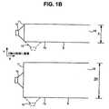
図1A及び図1Bは、以下の一部図面を理解するのに有用な幾何学的対象物を示す。図1Aは、二つの導波路6及び7の等角図である。導波路6及び7は、Y‐Z平面に矩形の断面を有し、Y及びZ方向の寸法よりもX方向の寸法が長い構造として示されている。導波路6のY‐Z平面の面積(以下、“面積”と称する)はAで、Y軸に沿った線寸法(長さ寸法)はhである。ここでは、面積の変化について述べる。対応する図面では、面積の変化が、Y方向の寸法の変化によって示されていて、Z方向の寸法は一定に保たれている。例えば、面積2Aの導波路7を、Y軸に沿って長さhを2hに二倍にすることによって、対応する図面に示されている。図1Bは、図1Aの導波路をX‐Y平面の断面図として示し、いくつか追加要素を含む。特に断らない限り、以下の図面の導波路は、X‐Y平面の断面図として示され、最も長い寸法はX方向に沿っている。特に断らない限り、“長さ”は、導波路にわたる音響経路の長さを指称する。導波路は頻繁に曲げられるので、長さは、導波路を含むデバイスのX方向の寸法よりも長くなり得る。音響導波路は典型的に、少なくとも一つの開口端18を有していて、また、閉口端11を有し得る。音響ドライバ10は典型的には図示されるように閉口端11に取り付けられるが、破線で示されるように壁13の一つに取り付けられ得る。以下の図面では、音響ドライバは閉口端11に取り付けられているものとして示される。 1A and 1B show geometric objects useful for understanding the following partial drawings. FIG. 1A is an isometric view of two
図2は第一の導波路アセンブリ100を示す。音響ドライバ10は、導波路の動作周波数範囲にわたって低ロス(低損失)、好ましくは実質的にロスレス(損失なし)の導波路12Aの一端に取り付けられる。導波路12Aは、断面積A及び有効音響長さlを有する。導波路は、導波路の有効音響長さによって基本的には決められる同調周波数(チューニング周波数)を有し、その有効音響長さは物理的長さに端効果補正を足したものである。端効果補正は、推定方法を用いて又は経験的に決められる。簡単のため、図面では、長さlは、物理的長さとして示され、“長さ”という用語は、有効音響長さを指称するものとする。導波路12Aは体積lAを有する。 FIG. 2 shows the
図3Aは第二の導波路アセンブリを示す。音響ドライバ10は、導波路の動作周波数範囲にわたって低ロス、好ましくは実質的にロスレスの導波路12Bに結合される。導波路12Bは、物理的長さβl及び断面積βAを有し、ここで、βは1未満の係数である。導波路12Bの体積は、β2lAである。音響体積部つまりチャンバ22は、開口部34によって導波路12Bに音響的に結合される。チャンバ22の体積は、lA−β2lAであり、導波路12Bの体積にチャンバ22の体積を足したものが、図2の導波路12Aの体積と同じになる。チャンバ22の効果は、導波路12Bが、長さが短いにもかかわらず、図2の導波路12Aと本質的に同じ同調周波数を有するようにすることである。図3Aの導波路の利点は、チャンバ22が正確な体積を有する限りにおいて、そのチャンバ22が多様な形状となり得ることである(以下のヘルムホルツ共鳴器の議論及び図6A及び図6Bの議論を除く)。例えば、図3Bに示されるように、チャンバ22の壁は、緩やかに湾曲した表面31を形成し得て、その表面が導波路12Bの壁を形成する。緩やかな湾曲を有する導波路は、より急な湾曲や方向の変化を有する導波路よりも、乱流や望ましくないノイズが少なく、また、空間を効率的に使える。予定の体積が維持されている限りにおいて、チャンバ22の寸法は、多様な値を有し得るが、以下の図6A及び図6Bの議論は除く。FIG. 3A shows a second waveguide assembly. The
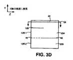
図3C及び図3Dは、導波路アセンブリのY‐Z平面の断面図を示し、X方向の寸法(導波路の最も長い寸法)は紙面に垂直である。図3Cの導波路では、チャンバ22が、導波路12BのY及びZ方向の寸法よりも大きなY方向及びZ方向の寸法を有していて、チャンバが導波路を部分的に又は完全に包み込んでいる。必要であれば、例えば製造を簡単にするため、バリア46若しくはバリア48又はこれらを両方とも導波路12B、チャンバにそれぞれ配置し得て、(二つの導波路12B‐1及び12B‐2、二つのチャンバ22A及び22B、又はこれら全部が存在するようにして)、あたかもバリアが存在しないのと同じような音響的な結果を達成する。視線52、54,56は以下で参照する。高周波数ピークをなくすため、図3Aの導波路及び以下の図面の全ての導波路には、特許文献4による耐音響材料が少量存在し得る。 3C and 3D show cross-sectional views of the waveguide assembly in the YZ plane, with the dimension in the X direction (the longest dimension of the waveguide) being perpendicular to the page. In the waveguide of FIG. 3C, the
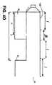
図3A及び図3Bに示されるように導波路の断面積及び長さを減少させ、また、導波路にチャンバを追加するというコンセプトは、導波路(例えばステップ型導波路)全体に対してだけではなく、導波路の一部(例えばステップ型導波路のステップ部分)に適用可能である。図4Aは、特許文献2によるステップ型導波路12Cを示す。音響ドライバ10は、ステップ型導波路12Cの一端に取り付けられる。ステップ型導波路12Cは、導波路の長さ方向に沿って四つの部分24〜27を有し、部分24は音響ドライバに隣接し、部分27は導波路の開口端18に隣接する。これら部分は、実質的に長さlのものである。部分24は、断面積A1を有し、部分25は、A1よりも大きな断面積A2を有し、部分26は、断面積A3を有し、部分27は、A3よりも大きな断面積A4を有する。部分24の体積V1はA1lであり、部分25の体積V2はA2lであり、部分26の体積V3はA3lであり、部分27の体積V4はA4lである。従来の導波路では、周囲環境に面する音響ドライバの表面(以下、外面と称する)からの放射は、導波路内に面する音響ドライバの表面からの放射とは位相がずれている。導波路の有効音響長さに等しい波長では、導波路からの放射と、導波路の外面からの放射とは破壊的に干渉し、導波路及び音響ドライバの放射の組み合わせを減じる。図4Aによる導波路システムでは、導波路からの放射は、音響ドライバの外面からの放射よりも大きいので、導波路及び外面からの放射の組み合わせにおけるディップがなくなる。図4Aの導波路アセンブリの一実施形態では、A1=A3、A2=A4であり、
図4Bは、導波路に音響的に結合されたチャンバを用いた導波路システムを示し、その導波路が、対応する従来の導波路よりも短くなっている。音響ドライバ10は、導波路12Dの一端に取り付けられている。導波路12D及び以下の図面の導波路は、導波路の動作周波数範囲にわたって低ロス、好ましくは実質的にロスレスである。導波路12Dは、図4Aの導波路の部分24及び26の断面積A1に等しい断面積を有する。図4Aの部分25及び27はそれぞれ部分25’、27’に置換されている。部分25’及び27’は、長さβlと、βA2に等しい断面積A’2を有し、ここで、βは0よりも大きく1未満の数である。本例では、
開口部34又は38は、それぞれチャンバ22又は29と共に、導波路システムの動作に悪い音響効果を有し得るヘルムホルツ共鳴器を形成し得るような面積を有し得る。ヘルムホルツ共鳴器については、例えば、非特許文献1に説明されている。しかしながら、開口部34及びチャンバ22の寸法は、ヘルムホルツ共鳴周波数が、導波路システムの動作に悪影響を与えない周波数、又は導波路の動作周波数範囲外の周波数であるように、選択可能である。ヘルムホルツ共鳴周波数が導波路の動作周波数外であるように寸法を選択することは、チャンバ22及び29に対するそれぞれ開口部34及び38の幅を、チャンバの幅に近く(例えばチャンバの幅の50%よりも大きく)することによってなすことができる。 The
図4Bの導波路12Dの同調は、図4Aの導波路12Cの同調と本質的には同じである。図4Bの部分24’及び26’は、図4Aの部分24及び26と同じ導波路の同調に対する効果を有する。図4Bの部分25’及び27’の物理的長さは、図1の部分25及び27の物理的長さlよりも短いβl(β<1)であるが、図4Bの部分25’及び27’は、図4Aの部分25及び27と同じ導波路の同調に対する効果を有する。 The tuning of the
上述の図面は単に例示的なものであり、包括的なものではなく、多様な変形例が考えられる。例えば、導波路が四つよりも多くの部分を有したり、部分25’及び27’等の部分が異なる長さを有したり、部分25’及び27’等の部分の体積が異なったり、V3及びV4等の体積の組み合わせがV2に等しくなかったり、以下で説明するように、チャンバの異なる構成が考えられる(例えば、以下で説明するように、チャンバの数が異なったり、チャンバが異なる体積、形状、導波路に沿った配置を有したりする)。The drawings described above are merely illustrative and are not exhaustive, and various modifications are possible. For example, the waveguide has more than four parts, parts such as parts 25 'and 27' have different lengths, parts 25 'and 27' etc. have different volumes, Combinations of volumes such as V3 and V4 are not equal to V2 , or different configurations of chambers are possible, as will be described below (eg, different numbers of chambers, May have different volumes, shapes, and arrangements along the waveguide).
より短い長さの導波路で同じ同調周波数を提供することに加えて、図4Bの導波路システムは、対応する波長が導波路の有効長さに等しい周波数における、音響ドライバ及び導波路の出力の組み合わせのディップをなくす点に関して、図4Aと同じ利点を有する。こうした周波数において、導波路の音響出力は、音響ドライバによって周囲環境に直接放射される音響出力よりも大きくて、導波路及び音響ドライバからの放射の組み合わせが、従来の導波路システムからの出力の組み合わせよりも大きくなる。また、図4Bの導波路アセンブリは、図4Aの導波路アセンブリよりも、急な面積の不連続性において生じ得るウインドノイズ(風切音)が少ない。 In addition to providing the same tuning frequency with shorter length waveguides, the waveguide system of FIG. 4B allows the output of the acoustic driver and waveguide at a frequency where the corresponding wavelength is equal to the effective length of the waveguide. It has the same advantages as FIG. 4A in terms of eliminating the combination dip. At these frequencies, the acoustic output of the waveguide is greater than the acoustic output radiated directly by the acoustic driver into the surrounding environment, and the combination of radiation from the waveguide and the acoustic driver is a combination of outputs from conventional waveguide systems. Bigger than. Also, the waveguide assembly of FIG. 4B has less wind noise (wind noise) that can occur at a steep area discontinuity than the waveguide assembly of FIG. 4A.
図4Cは、図4Bの導波路アセンブリの変形例を示す。図4Cの導波路アセンブリでは、図4Bのチャンバ22が、チャンバ22A及び22Bに置換されていて、チャンバ22A及び22Bの総体積がチャンバ22の体積に等しい。チャンバ22Aへの入口34Aは、音響ドライバからの距離d1に、l<d1<l+(βl/2)となるように、一例ではd1=l+(βl/4)となるように配置され、チャンバ22Bへの入口34Bは、音響ドライバからの距離d2に、l+(βl/2)<d2<l+βlとなるように、一例ではd2=l+(3βl/4)となるように配置される。図4Bのチャンバ29はチャンバ29A及び29Bに置換されていて、チャンバ29A及び29Bの総体積がチャンバ29の体積に等しい。チャンバ29Aへの入口38Aは、音響ドライバからの距離d3に、l+βl+l<d3<l+βl+l+(βl/2)となるように、一例ではd3=l+βl+l+(βl/4)となるように配置され、チャンバ29Bへの入口38Bは、音響ドライバからの距離d4に、l+βl+l+(βl/2)<d4<l+βl+l+βlとなるように、一例ではd4=l+βl+l+(3βl/4)となるように配置される。チャンバ22A及び22Bの導波路アセンブリの同調の効果は、図4Bのチャンバ22の効果と実質的に同じであり、チャンバ29A及び29Bの導波路アセンブリの同調の効果は、図4Bのチャンバ29の効果と実質的に同じであり、波長が導波路の有効長さに等しい周波数における、導波路アセンブリの出力のディップを軽減するという同じ有利な効果を有する。一般的に、複数のチャンバを用いることによって、同調周波数を、図4Aの導波路等のような等価なステップ型導波路の同調周波数により適合させることができる。FIG. 4C shows a variation of the waveguide assembly of FIG. 4B. In the waveguide assembly of FIG. 4C,
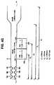
図4A、図4B及び図4Cの態様を組み合わせることができる。例えば、図4Dの導波路アセンブリは、導波路12Eに第一の部分において距離d1(ここでl<d1<l+βl)で結合されたチャンバ32と、距離d2=l+βl+lで始まるステップ部分27とを有する。図4Eの導波路アセンブリは、距離d1=lで始まるステップ部分25を備えた導波路12Fと、距離d2>l+l+lにチャンバ29とを有する。図4A、図4B及び図4Cの態様は、特許文献2の図1に示されるタイプの場合、本願の図4Fに示されるようにテーパ型導波路としても実施可能である。テーパ型導波路の使用について、チャンバのサイズと、導波路からチャンバへの開口部の位置とは、モデル化によって決定可能である。図4Fの導波路等のように実質的に連続的な壁を備えた導波路等の導波路は、急な面積の不連続部において生じる可能性のあるウインドノイズが少ない。図4Gの導波路アセンブリは、図4A〜図4Eの要素を取り入れた実際の導波路アセンブリの概略図である。図4Gの実施態様は、六つの2.25インチ音響ドライバ10A〜10Fを有し、図面に示された寸法を有する。The aspects of FIGS. 4A, 4B and 4C can be combined. For example, the waveguide assembly of FIG. 4D includes a chamber 32 coupled at a distance d1 (where l <d1 <l + βl) to a waveguide 12E in a first portion, and a
図5Aは、図4Bに概略的に示される導波路アセンブリの実施態様を示し、チャンバ22及び29の壁が複数の湾曲した表面31A及び31Bを形成し、それら表面31A及び31Bも導波路の壁を形成していることによって、空間を効率的に使用しつつ、より急な湾曲で生じるよりも乱流が少なくなっている。図5Aの参照符号は、図4Bの対応する導波路システムと同様に符号が付された要素を示す。図5Bは、図4Eに概略的に示される導波路の実施態様を示し、チャンバ29の壁及びステップ部分25が示されている。図5Bの参照符号は、図4Eの対応する導波路システムと同様に符号が付された要素を示す。 FIG. 5A shows an embodiment of the waveguide assembly schematically shown in FIG. 4B, where the walls of
図6A及び図6Bは、導波路アセンブリの他の特徴を示す。図6Aでは、導波路12Bは、開口部34を介してチャンバ22に音響的に結合されている。音波は、開口部34に入り、複数の音響経路(例えば、経路66A)に沿って、音波が音響境界にあたるまで、チャンバ22内を伝播する。音波が伝播する音響経路は多数存在し得るが、簡単のため、一つだけ示されている。 6A and 6B illustrate other features of the waveguide assembly. In FIG. 6A, the
一般的に、全ての音響経路の長さが、導波路12Bの有効音響長さの四分の一よりも顕著に短くなるようにチャンバを構成することが望ましい。音響経路のうち一つの長さが導波路の有効音響長さの四分の一よりも顕著に短くないと(例えば、10%未満ではない)、特定の周波数において、出力ディップが生じ得る。一例では、図4Bの導波路アセンブリと同様の導波路アセンブリは44Hzに同調されて、1.96m(6.43フィート)の有効音響長さを有する。1851.1cc(114立方インチ)の体積のチャンバ22は、閉口端11から39.6cm(15.6インチ)の位置で導波路12Bに結合される。チャンバ22は、長さ40.6cm(16インチ)の音響経路66A(図6Aを参照)を有し、つまり、導波路アセンブリの有効音響長さの(40.6cm/1.96m)×100=20.7%となる。周波数応答の望ましくないディップは、略200Hzで生じ得る。開口端11からのチャンバ22の距離等の因子に応じて、音響経路66Aの長さが25.4cm(10インチ)の短さ、つまり、導波路12Bの有効音響長さの(25.4cm/1.96m)×100=13.0%の場合に、周波数応答のディップが生じ得る。 In general, it is desirable to configure the chamber so that the length of all acoustic paths is significantly shorter than a quarter of the effective acoustic length of the
周波数応答のディップをなくす方法の一つは、音響経路66Aが、導波路システムの有効音響長さの10%未満の長さ(この場合、19.6cm)を有するようにチャンバ22を再構成することである。しかしながら、実際の導波路では、音響経路66Aが、導波路システムの有効音響長さの10%未満の長さを有するように再構成することが難しいことがある。 One way to eliminate the frequency response dip is to reconfigure the
周波数応答のディップをなくす他の方法は、66A等の音響経路の長さを周波数応答のディップを起さない長さに変化させる構造をチャンバ22に追加することである。図6Bは、音響経路66Bが50.8±1.3cm(20±0.5インチ)となるようにチャンバ内に挿入されたバッフル42を備えた図6Aの導波路システムを示す。図6Bの導波路システムは、図6Aの導波路システムの周波数応答のディップを有さない。ディップが生じ得る経路の長さ、ディップが生じない経路の長さの範囲、導波路の端に対して相対的なチャンバの開口部の配置に関する経路の長さの変化は、モデル化や実験によって決定可能である。図6A及び図6Bに示される状況では、許容範囲(ディップが生じない経路の長さの範囲)が広くなるので、経路の長さを短くすることが一般的に望ましい。上述の例では、25.4cm未満の長さが適切であるが、より長い音響経路の許容範囲はわずか±1.3cmである。 Another way to eliminate the frequency response dip is to add a structure to the
図7A及び図7Bは、これまでの図面で概略的に示された特徴を有する導波路アセンブリを取り入れたオーディオ再生機器の実際の実施態様を示す。図7A及び図7Bの要素は、これまでの図面の同様に符号の付された要素に対応する。図7A及び図7Bの破線は、チャンバ22及び29の境界を示す。図7Aは、オーディオ再生機器のX‐Z平面の断面図である。導波路アセンブリ12Bは、図3Cの導波路アセンブリの形状を有し、その断面は、図3Cの視線52又は54に対応する視線に沿ったものであり、視線52及び54に対応する視線に沿った断面は実質的に同一である。バリア46(図3のものであるが、図示せず)が存在し、二つの導波路を有する導波路アセンブリとなっている。図7Bは、図3Cの視線56に対応する視線に沿った、X‐Z平面の断面である。音響ドライバ10(これまでの図面のもの)は、図示されてはいないが、導波路12Bに結合される。コンパートメント58及び60は、高周波数音響ドライバ(図示せず)用であり、導波路アセンブリに密接な関係はない。図7A及び図7Bの実施態様では、チャンバ22の体積V1は略1861cm3(114立方インチ)であり、チャンバ29の体積V2は略836cm3(51立方インチ)であり、導波路の物理的長さは略132.1cm(52インチ)であり、チャンバ22に対する開口部34の中心は、開口端11から略39.6cm(15.6インチ)に位置し、開口部34の幅は略3.8cm(1.5インチ)であり、チャンバ29に対する開口部38の中心は、導波路の開口端18から略11.7cm(4.6インチ)であり、開口部38の幅は略3.8cm(1.5インチ)であり、導波路は略44Hzに同調されている。7A and 7B show an actual embodiment of an audio playback device incorporating a waveguide assembly having the features schematically shown in the previous drawings. Elements in FIGS. 7A and 7B correspond to like-labeled elements in the previous drawings. The dashed lines in FIGS. 7A and 7B indicate the boundaries of the
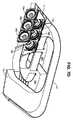
図7Cの導波路アセンブリは、二つの低周波数音響ドライバ10A及び10Bを有する。図7Cの要素は、これまでの図面の同様に符号の付された要素に対応する。導波路12の第二の部分は、開口部34A及び34Bによってそれぞれ二つのチャンバ22A及び22Bに結合されている。導波路12の第四の部分は開口部38によって単一のチャンバ26に結合されている。導波路12の壁はチャンバ22A及び22Bの壁(この応用のために、壁と同じアウトラインに実質的に従うことを含む)を形成し、チャンバ22A及び22Bを実質的に包み込んでいる。チャンバ22A及び22Bは、“ティアドロップ”型であり、導波路用の大きな同調半径を提供し、より小さな同調半径や急な湾曲の場合に生じる乱流を少なくする。チャンバ26は、低気流速度の大型チャンバを提供し、電子部品36用に便利な配置を提供する。低気流速度によって、電子部品36にあたる際の乱流が少なくなる。チャンバ26の不規則で何回も湾曲した形状によって、小型デバイス筐体34内にアセンブリを効率的に適合させることができる。高周波数音響ドライバは導波路12内には放射しない。 The waveguide assembly of FIG. 7C has two low frequency
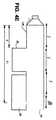
図7Dの導波路アセンブリは、図4Fに概略的に示される導波路の実際の実施態様である。図7Dの要素は、図4Fの同様の参照符号に対応する。 The waveguide assembly of FIG. 7D is an actual implementation of the waveguide schematically shown in FIG. 4F. Elements in FIG. 7D correspond to similar reference numbers in FIG. 4F.
他の実施形態は特許請求の範囲内に存する。 Other embodiments are within the scope of the claims.
10 音響ドライバ
11 閉口端(音響ドライバ端)
12 導波路
18 開口端
22、29 チャンバ(音響体積部)
34、38 開口部
42 バッフル
46、48 バリア10
12
34, 38
Claims (15)
Translated fromJapanese第一の表面が前記音響導波路内に音波を放射して該音波が前記音響導波路から放射されるように、前記音響導波路に取り付けられた音響ドライバと、
前記音響導波路から放射される音波の振幅を増大させるために、前記音響導波路に音響的に結合された音響体積部と、を備えたラウドスピーカアセンブリ。An acoustic waveguide;
An acoustic driver attached to the acoustic waveguide such that a first surface emits acoustic waves into the acoustic waveguide and the acoustic waves are emitted from the acoustic waveguide;
A loudspeaker assembly comprising: an acoustic volume acoustically coupled to the acoustic waveguide for increasing the amplitude of sound waves emitted from the acoustic waveguide.
前記ラウドスピーカアセンブリの有効音響長さの10%未満の長さ、又は、
前記ラウドスピーカアセンブリの有効音響長さの10%よりも大きく周波数応答のディップを生じさせない長さ範囲内の長さを有する、請求項1に記載のラウドスピーカアセンブリ。The acoustic waveguide has an effective acoustic length, the acoustic volume has a plurality of acoustic paths, and each acoustic path is
Less than 10% of the effective acoustic length of the loudspeaker assembly, or
The loudspeaker assembly of claim 1, wherein the loudspeaker assembly has a length that is greater than 10% of the effective acoustic length of the loudspeaker assembly and does not cause a dip in frequency response.
第一の放射表面及び第二の放射表面を有する音響ドライバであって、前記第一の放射表面が前記音響導波路内に音響エネルギーを放射し、音響放射が前記音響導波路から放射されるように前記音響導波路に取り付けられた音響ドライバと、を備えたラウドスピーカ装置であって、
前記第二の放射表面からの放射が前記音響導波路からの放射と位相がずれているキャンセル周波数が、前記音響導波路からの放射と前記第二の放射表面からの放射との間の破壊的な干渉をもたらし、前記キャンセル周波数における前記ラウドスピーカ装置からの音響出力の減少をもたらすことを特徴とし、
前記音響導波路からの放射の振幅を増大させて前記キャンセル周波数における前記ラウドスピーカ装置からの音響出力の減少を少なくするために前記音響導波路に音響的に結合された音響体積部を更に備えたラウドスピーカ装置。An acoustic waveguide;
An acoustic driver having a first radiating surface and a second radiating surface, wherein the first radiating surface radiates acoustic energy into the acoustic waveguide such that acoustic radiation is radiated from the acoustic waveguide. A loudspeaker device comprising: an acoustic driver attached to the acoustic waveguide;
The cancellation frequency at which the radiation from the second radiation surface is out of phase with the radiation from the acoustic waveguide is destructive between the radiation from the acoustic waveguide and the radiation from the second radiation surface. Resulting in a decrease in sound output from the loudspeaker device at the cancellation frequency,
And further comprising an acoustic volume acoustically coupled to the acoustic waveguide to increase the amplitude of radiation from the acoustic waveguide to reduce a decrease in acoustic output from the loudspeaker device at the cancellation frequency. Loud speaker device.
Applications Claiming Priority (3)
| Application Number | Priority Date | Filing Date | Title |
|---|---|---|---|
| US12/020,978US8351629B2 (en) | 2008-02-21 | 2008-02-21 | Waveguide electroacoustical transducing |
| US12/020,978 | 2008-02-21 | ||
| PCT/US2009/032241WO2009105313A1 (en) | 2008-02-21 | 2009-01-28 | Waveguide electroacoustical transducing |
Publications (3)
| Publication Number | Publication Date |
|---|---|
| JP2011512108Atrue JP2011512108A (en) | 2011-04-14 |
| JP2011512108A5 JP2011512108A5 (en) | 2012-08-02 |
| JP5472880B2 JP5472880B2 (en) | 2014-04-16 |
Family
ID=40496575
Family Applications (1)
| Application Number | Title | Priority Date | Filing Date |
|---|---|---|---|
| JP2010546815AActiveJP5472880B2 (en) | 2008-02-21 | 2009-01-28 | Waveguide electroacoustic conversion |
Country Status (6)
| Country | Link |
|---|---|
| US (1) | US8351629B2 (en) |
| EP (1) | EP2258115B1 (en) |
| JP (1) | JP5472880B2 (en) |
| CN (1) | CN101933341B (en) |
| CA (1) | CA2710025C (en) |
| WO (1) | WO2009105313A1 (en) |
Cited By (3)
| Publication number | Priority date | Publication date | Assignee | Title |
|---|---|---|---|---|
| JP2013538538A (en)* | 2010-09-21 | 2013-10-10 | ボーズ・コーポレーション | Low frequency enclosure for video display devices |
| JP2013538509A (en)* | 2010-08-12 | 2013-10-10 | ボーズ・コーポレーション | Active and passive directional acoustic radiation |
| WO2019235317A1 (en)* | 2018-06-08 | 2019-12-12 | ヤマハ株式会社 | Speaker |
Families Citing this family (18)
| Publication number | Priority date | Publication date | Assignee | Title |
|---|---|---|---|---|
| US8615097B2 (en) | 2008-02-21 | 2013-12-24 | Bose Corportion | Waveguide electroacoustical transducing |
| US8351629B2 (en) | 2008-02-21 | 2013-01-08 | Robert Preston Parker | Waveguide electroacoustical transducing |
| US8351630B2 (en) | 2008-05-02 | 2013-01-08 | Bose Corporation | Passive directional acoustical radiating |
| WO2011007436A1 (en)* | 2009-07-16 | 2011-01-20 | 株式会社 東芝 | Acoustic reproduction device |
| US8094855B2 (en)* | 2009-09-08 | 2012-01-10 | Clements Philip R | Inverse horn loudspeakers |
| US8139774B2 (en) | 2010-03-03 | 2012-03-20 | Bose Corporation | Multi-element directional acoustic arrays |
| US20110242504A1 (en)* | 2010-03-31 | 2011-10-06 | Andrew Olcott | Rear Projection System |
| US8553894B2 (en) | 2010-08-12 | 2013-10-08 | Bose Corporation | Active and passive directional acoustic radiating |
| US9571921B2 (en)* | 2011-08-22 | 2017-02-14 | Knowles Electronics, Llc | Receiver acoustic low pass filter |
| US9173018B2 (en) | 2012-06-27 | 2015-10-27 | Bose Corporation | Acoustic filter |
| US9451355B1 (en) | 2015-03-31 | 2016-09-20 | Bose Corporation | Directional acoustic device |
| US10057701B2 (en) | 2015-03-31 | 2018-08-21 | Bose Corporation | Method of manufacturing a loudspeaker |
| BR112018069250A2 (en)* | 2016-03-31 | 2019-01-22 | Sony Corp | acoustic tube and acoustic playback device |
| EP3556111B1 (en) | 2016-12-14 | 2021-10-06 | Dolby Laboratories Licensing Corporation | Multi-driver loudspeaker with cross-coupled dual wave-columns |
| EP3696618B1 (en) | 2019-02-14 | 2024-11-20 | Montres Breguet S.A. | Chiming or musical watch with arrangement for guiding the acoustic waves |
| ES2997357T3 (en)* | 2019-09-03 | 2025-02-17 | Genelec Oy | Directive multiway loudspeaker with a waveguide |
| DE102020201533A1 (en)* | 2020-02-07 | 2021-08-12 | Fraunhofer-Gesellschaft zur Förderung der angewandten Forschung e.V. | DEVICE FOR SOUND CONVERSION WITH AN ACOUSTIC FILTER |
| US11640816B1 (en)* | 2022-02-23 | 2023-05-02 | Acoustic Metamaterials LLC | Metamaterial acoustic impedance matching device for headphone-type devices |
Citations (6)
| Publication number | Priority date | Publication date | Assignee | Title |
|---|---|---|---|---|
| JPS6468099A (en)* | 1987-09-08 | 1989-03-14 | Matsushita Electric Industrial Co Ltd | Speaker system |
| JPH01241296A (en)* | 1988-03-23 | 1989-09-26 | Yamaha Corp | Acoustic equipment |
| JPH04336795A (en)* | 1991-05-13 | 1992-11-24 | Mitsubishi Electric Corp | Speaker system |
| JPH06253383A (en)* | 1993-02-24 | 1994-09-09 | Matsushita Electric Ind Co Ltd | Speaker device |
| US5740259A (en)* | 1992-06-04 | 1998-04-14 | Bose Corporation | Pressure wave transducing |
| JP2000092583A (en)* | 1998-09-03 | 2000-03-31 | Bose Corp | Electroacoustic transducer by waveguide |
Family Cites Families (131)
| Publication number | Priority date | Publication date | Assignee | Title |
|---|---|---|---|---|
| US1577880A (en) | 1925-10-31 | 1926-03-23 | Alexander A S Stuart | Surgical knife |
| US1755636A (en) | 1927-09-22 | 1930-04-22 | Radio Patents Corp | Loud-speaker |
| US2293181A (en) | 1940-07-17 | 1942-08-18 | Int Standard Electric Corp | Sound absorbing apparatus |
| GB631799A (en) | 1946-06-24 | 1949-11-10 | John Forrester | Improvements in or relating to loud speakers |
| FR1359616A (en) | 1960-07-05 | 1964-04-30 | Csf | New acoustic wave projector |
| US3378814A (en) | 1966-06-13 | 1968-04-16 | Gen Instrument Corp | Directional transducer |
| US3486578A (en) | 1967-12-21 | 1969-12-30 | Lawrence Albarino | Electro-mechanical reproduction of sound |
| US4965776A (en) | 1969-01-22 | 1990-10-23 | The United States Of America As Represented By The Secretary Of The Navy | Planar end-fire array |
| SE358800B (en) | 1972-02-29 | 1973-08-06 | Bostedt J | |
| US3940576A (en) | 1974-03-19 | 1976-02-24 | Schultz Herbert J | Loudspeaker having sound funnelling element |
| US4340778A (en) | 1979-11-13 | 1982-07-20 | Bennett Sound Corporation | Speaker distortion compensator |
| US4373606A (en) | 1979-12-31 | 1983-02-15 | Clements Philip R | Loudspeaker enclosure and process for generating sound radiation |
| US4628528A (en) | 1982-09-29 | 1986-12-09 | Bose Corporation | Pressure wave transducing |
| US4616731A (en)* | 1984-03-02 | 1986-10-14 | Robinson James R | Speaker system |
| US4747142A (en) | 1985-07-25 | 1988-05-24 | Tofte David A | Three-track sterophonic system |
| US4930596A (en) | 1987-06-16 | 1990-06-05 | Matsushita Electric Industrial Co., Ltd. | Loudspeaker system |
| US5012890A (en)* | 1988-03-23 | 1991-05-07 | Yamaha Corporation | Acoustic apparatus |
| US4942939A (en)* | 1989-05-18 | 1990-07-24 | Harrison Stanley N | Speaker system with folded audio transmission passage |
| DE59002494D1 (en) | 1989-06-12 | 1993-09-30 | Josef Gail | PISTON MACHINE. |
| FR2653630B1 (en) | 1989-10-23 | 1994-01-14 | Di Carlo Gilles Scotto | ACOUSTIC SPEAKER STRUCTURE. |
| NL8902831A (en)* | 1989-11-16 | 1991-06-17 | Philips Nv | SPEAKER SYSTEM CONTAINING A HELMHOLTZ RESONATOR COUPLED WITH AN ACOUSTIC TUBE. |
| JPH03236691A (en) | 1990-02-14 | 1991-10-22 | Hitachi Ltd | Audio circuit for television receiver |
| US5105905A (en) | 1990-05-07 | 1992-04-21 | Rice Winston C | Co-linear loudspeaker system |
| US5197103A (en)* | 1990-10-05 | 1993-03-23 | Kabushiki Kaisha Kenwood | Low sound loudspeaker system |
| DE4036374A1 (en) | 1990-11-15 | 1992-05-21 | Bsg Schalttechnik | CHARGING DEVICE FOR RECHARGEABLE BATTERIES |
| US5373564A (en) | 1992-10-02 | 1994-12-13 | Spear; Robert J. | Transmission line for planar waves |
| US5426702A (en) | 1992-10-15 | 1995-06-20 | U.S. Philips Corporation | System for deriving a center channel signal from an adapted weighted combination of the left and right channels in a stereophonic audio signal |
| DE69423922T2 (en) | 1993-01-27 | 2000-10-05 | Koninkl Philips Electronics Nv | Sound signal processing arrangement for deriving a central channel signal and audio-visual reproduction system with such a processing arrangement |
| US6002781A (en)* | 1993-02-24 | 1999-12-14 | Matsushita Electric Industrial Co., Ltd. | Speaker system |
| US6278789B1 (en) | 1993-05-06 | 2001-08-21 | Bose Corporation | Frequency selective acoustic waveguide damping |
| US5400408A (en) | 1993-06-23 | 1995-03-21 | Apple Computer, Inc. | High performance stereo sound enclosure for computer visual display monitor and method for construction |
| US5802194A (en) | 1993-10-01 | 1998-09-01 | Sony Corporation | Stereo loudspeaker system with tweeters mounted on rotatable enlongated arms |
| US5742690A (en) | 1994-05-18 | 1998-04-21 | International Business Machine Corp. | Personal multimedia speaker system |
| DK171338B1 (en) | 1994-10-10 | 1996-09-09 | Brueel & Kjaer As | Circular sound source |
| US6223853B1 (en) | 1994-12-23 | 2001-05-01 | Graeme John Huon | Loudspeaker system incorporating acoustic waveguide filters and method of construction |
| JP3514857B2 (en) | 1995-02-06 | 2004-03-31 | 株式会社東芝 | TV set speaker system |
| GB2302231B (en)* | 1995-03-14 | 1999-01-13 | Matsushita Electric Industrial Co Ltd | Speaker system |
| US5610992A (en) | 1995-03-17 | 1997-03-11 | Hewlett-Packard Company | Portable electronic device having a ported speaker enclosure |
| US5673329A (en) | 1995-03-23 | 1997-09-30 | Wiener; David | Omni-directional loudspeaker system |
| US6075868A (en)* | 1995-04-21 | 2000-06-13 | Bsg Laboratories, Inc. | Apparatus for the creation of a desirable acoustical virtual reality |
| US5644109A (en) | 1995-05-30 | 1997-07-01 | Newman; Ottis G. | Speaker enclosure |
| US5870484A (en) | 1995-09-05 | 1999-02-09 | Greenberger; Hal | Loudspeaker array with signal dependent radiation pattern |
| US5794164A (en) | 1995-11-29 | 1998-08-11 | Microsoft Corporation | Vehicle computer system |
| US5821471A (en) | 1995-11-30 | 1998-10-13 | Mcculler; Mark A. | Acoustic system |
| US5828759A (en) | 1995-11-30 | 1998-10-27 | Siemens Electric Limited | System and method for reducing engine noise |
| US5726395A (en) | 1996-10-30 | 1998-03-10 | Sony Corporation | Isolation/damping mounting system for loudspeaker crossover network |
| US5963640A (en) | 1996-11-07 | 1999-10-05 | Ericsson, Inc. | Radiotelephone having an acoustical wave guide coupled to a speaker |
| DE19648986C1 (en) | 1996-11-26 | 1998-04-09 | Raida Hans Joachim | Directional rod-type acoustic radiator |
| US5809153A (en) | 1996-12-04 | 1998-09-15 | Bose Corporation | Electroacoustical transducing |
| US5832099A (en) | 1997-01-08 | 1998-11-03 | Wiener; David | Speaker system having an undulating rigid speaker enclosure |
| US7016501B1 (en) | 1997-02-07 | 2006-03-21 | Bose Corporation | Directional decoding |
| US5815589A (en) | 1997-02-18 | 1998-09-29 | Wainwright; Charles E. | Push-pull transmission line loudspeaker |
| US5881989A (en) | 1997-03-04 | 1999-03-16 | Apple Computer, Inc. | Audio enclosure assembly mounting system and method |
| US5732145A (en) | 1997-03-18 | 1998-03-24 | Tsao; Ye-Ming | Speaker system and device rack arrangement |
| US6067362A (en) | 1997-04-24 | 2000-05-23 | Bose Corporation | Mechanical resonance reducing |
| WO1998051122A1 (en) | 1997-05-08 | 1998-11-12 | Ericsson Inc. | Horn loaded microphone with helmholtz resonator attenuator |
| JPH11220789A (en) | 1998-01-30 | 1999-08-10 | Sony Corp | Electrical acoustic conversion device |
| US6144751A (en) | 1998-02-24 | 2000-11-07 | Velandia; Erich M. | Concentrically aligned speaker enclosure |
| US6359994B1 (en) | 1998-05-28 | 2002-03-19 | Compaq Information Technologies Group, L.P. | Portable computer expansion base with enhancement speaker |
| DE19861018C2 (en) | 1998-12-15 | 2001-06-13 | Fraunhofer Ges Forschung | Controlled acoustic waveguide for sound absorption |
| US6928169B1 (en) | 1998-12-24 | 2005-08-09 | Bose Corporation | Audio signal processing |
| US6374120B1 (en) | 1999-02-16 | 2002-04-16 | Denso Corporation | Acoustic guide for audio transducers |
| US6694200B1 (en) | 1999-04-13 | 2004-02-17 | Digital5, Inc. | Hard disk based portable device |
| KR100308042B1 (en) | 1999-04-15 | 2001-09-26 | 구자홍 | multiple damping device for speaker system in video display appliance |
| US6477042B1 (en) | 1999-11-18 | 2002-11-05 | Siemens Energy & Automation, Inc. | Disk drive mounting system for absorbing shock and vibration in a machining environment |
| US6704425B1 (en) | 1999-11-19 | 2004-03-09 | Virtual Bass Technologies, Llc | System and method to enhance reproduction of sub-bass frequencies |
| US6255800B1 (en) | 2000-01-03 | 2001-07-03 | Texas Instruments Incorporated | Bluetooth enabled mobile device charging cradle and system |
| US6431309B1 (en) | 2000-04-14 | 2002-08-13 | C. Ronald Coffin | Loudspeaker system |
| EP1148758A1 (en) | 2000-04-18 | 2001-10-24 | THOMSON multimedia S.A. | Cabinet for audio devices |
| US20010039200A1 (en) | 2000-04-20 | 2001-11-08 | Henry Azima | Portable communications equipment |
| US6791481B2 (en) | 2000-05-18 | 2004-09-14 | Echo Mobile Music, Llc | Portable CD-ROM/ISO to HDD/MP3 recorder with simultaneous CD-Read/MP3-Encode/HDD-Write, or HDD-Read/MP3-Decode, to play, power saving buffer, and enhanced sound output |
| CN1442029A (en) | 2000-07-17 | 2003-09-10 | 皇家菲利浦电子有限公司 | Stereo audio processing device for deriving auxiliary audio signals such as direction and centre audio signals |
| GB2369758A (en) | 2000-07-21 | 2002-06-05 | Media Tools Plc | Audio processing apparatus in the form of a personal computer |
| US6415036B1 (en) | 2000-08-24 | 2002-07-02 | Thomson Licensing, S.A. | Apparatus for reducing vibrations generated by a loudspeaker in a television cabinet |
| DE20019525U1 (en) | 2000-11-17 | 2001-01-04 | Holland, Bert E., Ringwood | Briefcase or carrying case with integrated speaker system |
| US7426280B2 (en)* | 2001-01-02 | 2008-09-16 | Bose Corporation | Electroacoustic waveguide transducing |
| US6597794B2 (en) | 2001-01-23 | 2003-07-22 | Hewlett-Packard Development Company, L.P. | Portable electronic device having an external speaker chamber |
| US20020115480A1 (en) | 2001-02-13 | 2002-08-22 | Huang Chih Chen | Adapter set |
| US8477958B2 (en) | 2001-02-26 | 2013-07-02 | 777388 Ontario Limited | Networked sound masking system |
| US6662627B2 (en) | 2001-06-22 | 2003-12-16 | Desert Research Institute | Photoacoustic instrument for measuring particles in a gas |
| GB0123451D0 (en) | 2001-09-28 | 2001-11-21 | Mitel Knowledge Corp | Device for reducing structural-acoustical coupling between the diaphragm vibration field and the enclosure acoustic modes |
| GB0124046D0 (en) | 2001-10-05 | 2007-01-10 | Bae Sema Ltd | Sonar localisation |
| KR100718613B1 (en) | 2001-10-22 | 2007-05-16 | 애플 인크. | How to Synchronize Media Contents of a Host Computer and Media Player |
| US20030167318A1 (en) | 2001-10-22 | 2003-09-04 | Apple Computer, Inc. | Intelligent synchronization of media player with host computer |
| AU2002358225A1 (en) | 2001-12-05 | 2003-06-17 | Koninklijke Philips Electronics N.V. | Circuit and method for enhancing a stereo signal |
| EP1487233A4 (en) | 2002-03-15 | 2005-12-07 | Sharp Kk | Image display device |
| US7618345B2 (en) | 2002-07-26 | 2009-11-17 | Unisen, Inc. | Exercise equipment with universal PDA cradle |
| US6820431B2 (en) | 2002-10-31 | 2004-11-23 | General Electric Company | Acoustic impedance-matched fuel nozzle device and tunable fuel injection resonator assembly |
| US20040204056A1 (en) | 2002-12-06 | 2004-10-14 | William Phelps | Charger with rotating pocket and detachable pocket insert |
| US8155342B2 (en) | 2002-12-11 | 2012-04-10 | Ira Marlowe | Multimedia device integration system |
| US20050239434A1 (en) | 2002-12-11 | 2005-10-27 | Marlowe Ira M | Multimedia device integration system |
| GB0304126D0 (en) | 2003-02-24 | 2003-03-26 | 1 Ltd | Sound beam loudspeaker system |
| US6792907B1 (en) | 2003-03-04 | 2004-09-21 | Visteon Global Technologies, Inc. | Helmholtz resonator |
| US7719830B2 (en) | 2005-05-09 | 2010-05-18 | Apple Inc. | Universal docking station for hand held electronic devices |
| US20050018839A1 (en) | 2003-07-23 | 2005-01-27 | Weiser William Bruce | Electronic device cradle organizer |
| US7542815B1 (en) | 2003-09-04 | 2009-06-02 | Akita Blue, Inc. | Extraction of left/center/right information from two-channel stereo sources |
| US7584820B2 (en) | 2004-03-19 | 2009-09-08 | Bose Corporation | Acoustic radiating |
| US20040234085A1 (en) | 2004-04-16 | 2004-11-25 | Lennox Timothy Jon | Portable audio amplifying apparatus for handheld multimedia devices and uses thereof |
| US8783574B2 (en) | 2004-05-05 | 2014-07-22 | Khyber Technologies Corporation | Peripheral unit adapted to variably sized handheld host devices |
| KR100663535B1 (en) | 2004-05-17 | 2007-01-02 | 삼성전자주식회사 | Speaker-compatible interchangeable mount / charger for portable devices |
| US7490044B2 (en) | 2004-06-08 | 2009-02-10 | Bose Corporation | Audio signal processing |
| US20060013411A1 (en) | 2004-07-14 | 2006-01-19 | Chung-Hung Lin | On a support seat of an audio player |
| GB2431314B (en) | 2004-08-10 | 2008-12-24 | 1 Ltd | Non-planar transducer arrays |
| US20060046778A1 (en) | 2004-08-30 | 2006-03-02 | Hembree Ryan M | System for listening to playback of music files by a portable audio device while in a vehicle |
| US7283634B2 (en) | 2004-08-31 | 2007-10-16 | Dts, Inc. | Method of mixing audio channels using correlated outputs |
| US8085962B2 (en) | 2004-09-01 | 2011-12-27 | Bose Corporation | Audio system for portable device |
| US7155214B2 (en) | 2004-09-09 | 2006-12-26 | Dana Innovations | I-port controller |
| JP2006125381A (en) | 2004-09-29 | 2006-05-18 | Toyoda Gosei Co Ltd | Resonator |
| KR101243687B1 (en) | 2004-11-23 | 2013-03-14 | 코닌클리케 필립스 일렉트로닉스 엔.브이. | A device and a method to process audio data, a computer program element and a computer-readable medium |
| US7668576B2 (en) | 2004-12-16 | 2010-02-23 | Dashjack, Inc. | Incorporating a portable digital music player into a vehicle audio system |
| US20060181840A1 (en) | 2005-01-05 | 2006-08-17 | Jonatan Cvetko | Cradle for portable devices on a vehicle |
| US20060253879A1 (en) | 2005-01-20 | 2006-11-09 | Ten Technology, Inc. | Mounting system for multimedia playback devices |
| SG127770A1 (en) | 2005-05-31 | 2006-12-29 | Creactive Technology Ltd | Methods of invoking various functions of a digitalmedia player using a single switch of the digital media player |
| US7480138B2 (en) | 2005-06-30 | 2009-01-20 | Symbol Technologies, Inc. | Reconfigurable mobile device docking cradle |
| GB0514361D0 (en) | 2005-07-12 | 2005-08-17 | 1 Ltd | Compact surround sound effects system |
| TWM285873U (en) | 2005-07-13 | 2006-01-11 | Lite On Technology Corp | Multimedia speaker mount |
| JP2007037058A (en) | 2005-07-29 | 2007-02-08 | Sony Corp | Speaker system |
| US7352567B2 (en) | 2005-08-09 | 2008-04-01 | Apple Inc. | Methods and apparatuses for docking a portable electronic device that has a planar like configuration and that operates in multiple orientations |
| GB2429573A (en) | 2005-08-23 | 2007-02-28 | Digifi Ltd | Multiple input and output media playing network |
| US7835537B2 (en) | 2005-10-13 | 2010-11-16 | Cheney Brian E | Loudspeaker including slotted waveguide for enhanced directivity and associated methods |
| GB2431813B (en) | 2005-10-28 | 2008-06-04 | Eleanor Johnson | Audio system |
| EP1946610A2 (en) | 2005-11-01 | 2008-07-23 | Koninklijke Philips Electronics N.V. | Sound reproduction system and method |
| CN101341479B (en) | 2005-12-12 | 2010-11-10 | 精工爱普生株式会社 | Video docking station for portable media player |
| US8045719B2 (en) | 2006-03-13 | 2011-10-25 | Dolby Laboratories Licensing Corporation | Rendering center channel audio |
| DE102007039598B4 (en) | 2006-09-05 | 2010-07-22 | DENSO CORPORATION, Kariya-shi | Ultrasonic sensor and obstacle detector device |
| US8103035B2 (en) | 2006-12-22 | 2012-01-24 | Bose Corporation | Portable audio system having waveguide structure |
| US8351629B2 (en) | 2008-02-21 | 2013-01-08 | Robert Preston Parker | Waveguide electroacoustical transducing |
| JP4655098B2 (en) | 2008-03-05 | 2011-03-23 | ヤマハ株式会社 | Audio signal output device, audio signal output method and program |
| TW200942063A (en) | 2008-03-20 | 2009-10-01 | Weistech Technology Co Ltd | Vertically or horizontally placeable combinative array speaker |
| US8345909B2 (en) | 2008-04-03 | 2013-01-01 | Bose Corporation | Loudspeaker assembly |
| US8351630B2 (en) | 2008-05-02 | 2013-01-08 | Bose Corporation | Passive directional acoustical radiating |
- 2008
- 2008-02-21USUS12/020,978patent/US8351629B2/enactiveActive
- 2009
- 2009-01-28JPJP2010546815Apatent/JP5472880B2/enactiveActive
- 2009-01-28WOPCT/US2009/032241patent/WO2009105313A1/enactiveApplication Filing
- 2009-01-28CNCN200980103524.0Apatent/CN101933341B/ennot_activeExpired - Fee Related
- 2009-01-28CACA2710025Apatent/CA2710025C/ennot_activeExpired - Fee Related
- 2009-01-28EPEP09712212.1Apatent/EP2258115B1/enactiveActive
Patent Citations (6)
| Publication number | Priority date | Publication date | Assignee | Title |
|---|---|---|---|---|
| JPS6468099A (en)* | 1987-09-08 | 1989-03-14 | Matsushita Electric Industrial Co Ltd | Speaker system |
| JPH01241296A (en)* | 1988-03-23 | 1989-09-26 | Yamaha Corp | Acoustic equipment |
| JPH04336795A (en)* | 1991-05-13 | 1992-11-24 | Mitsubishi Electric Corp | Speaker system |
| US5740259A (en)* | 1992-06-04 | 1998-04-14 | Bose Corporation | Pressure wave transducing |
| JPH06253383A (en)* | 1993-02-24 | 1994-09-09 | Matsushita Electric Ind Co Ltd | Speaker device |
| JP2000092583A (en)* | 1998-09-03 | 2000-03-31 | Bose Corp | Electroacoustic transducer by waveguide |
Cited By (5)
| Publication number | Priority date | Publication date | Assignee | Title |
|---|---|---|---|---|
| JP2013538509A (en)* | 2010-08-12 | 2013-10-10 | ボーズ・コーポレーション | Active and passive directional acoustic radiation |
| JP2013538538A (en)* | 2010-09-21 | 2013-10-10 | ボーズ・コーポレーション | Low frequency enclosure for video display devices |
| WO2019235317A1 (en)* | 2018-06-08 | 2019-12-12 | ヤマハ株式会社 | Speaker |
| JP2019213149A (en)* | 2018-06-08 | 2019-12-12 | ヤマハ株式会社 | Speaker |
| JP7135463B2 (en) | 2018-06-08 | 2022-09-13 | ヤマハ株式会社 | speaker |
Also Published As
| Publication number | Publication date |
|---|---|
| CN101933341B (en) | 2014-09-17 |
| CA2710025A1 (en) | 2009-08-27 |
| JP5472880B2 (en) | 2014-04-16 |
| WO2009105313A1 (en) | 2009-08-27 |
| EP2258115A1 (en) | 2010-12-08 |
| EP2258115B1 (en) | 2017-07-19 |
| CA2710025C (en) | 2015-06-16 |
| AU2009215768A1 (en) | 2009-08-27 |
| CN101933341A (en) | 2010-12-29 |
| US20090214066A1 (en) | 2009-08-27 |
| US8351629B2 (en) | 2013-01-08 |
Similar Documents
| Publication | Publication Date | Title |
|---|---|---|
| JP5472880B2 (en) | Waveguide electroacoustic conversion | |
| US8615097B2 (en) | Waveguide electroacoustical transducing | |
| JP2011512108A5 (en) | ||
| US9549242B2 (en) | Acoustic filter | |
| JP5759551B2 (en) | Low frequency enclosure for video display devices | |
| EP2328141A2 (en) | Acoustic resonator and sound chamber | |
| Tang | Narrow sidebranch arrays for low frequency duct noise control | |
| JP2010087174A (en) | Silencer for electronic equipment | |
| JP5817762B2 (en) | Sound equipment | |
| US20140291065A1 (en) | Loudspeaker having external extension | |
| EP2043382B1 (en) | Sound system | |
| US9473848B2 (en) | Transmission line loudspeaker | |
| JP2016194682A (en) | Noise reduction device | |
| AU2009215768B2 (en) | Waveguide electroacoustical transducing | |
| CN112219408B (en) | Loudspeaker | |
| HK1149411B (en) | Waveguide electroacoustical transducing | |
| HK1149411A (en) | Waveguide electroacoustical transducing | |
| JP4770477B2 (en) | Speaker unit | |
| JPH09307985A (en) | Speaker device | |
| JP2019191343A (en) | Noise reduction structure | |
| EP4230873A1 (en) | Noise reduced blower means and their use in electric power tools and devices | |
| JP3668678B2 (en) | Soundproof device | |
| JP2006207508A (en) | Fan noise reduction device and fan noise reduction method | |
| KR20250110916A (en) | Transformer-generated noise reduction devices and systems | |
| JP3170085U (en) | Reflective speaker |
Legal Events
| Date | Code | Title | Description |
|---|---|---|---|
| A131 | Notification of reasons for refusal | Free format text:JAPANESE INTERMEDIATE CODE: A131 Effective date:20111213 | |
| A601 | Written request for extension of time | Free format text:JAPANESE INTERMEDIATE CODE: A601 Effective date:20120313 | |
| A602 | Written permission of extension of time | Free format text:JAPANESE INTERMEDIATE CODE: A602 Effective date:20120321 | |
| A524 | Written submission of copy of amendment under article 19 pct | Free format text:JAPANESE INTERMEDIATE CODE: A524 Effective date:20120613 | |
| A131 | Notification of reasons for refusal | Free format text:JAPANESE INTERMEDIATE CODE: A131 Effective date:20121218 | |
| A601 | Written request for extension of time | Free format text:JAPANESE INTERMEDIATE CODE: A601 Effective date:20130318 | |
| A602 | Written permission of extension of time | Free format text:JAPANESE INTERMEDIATE CODE: A602 Effective date:20130326 | |
| A521 | Request for written amendment filed | Free format text:JAPANESE INTERMEDIATE CODE: A523 Effective date:20130618 | |
| TRDD | Decision of grant or rejection written | ||
| A01 | Written decision to grant a patent or to grant a registration (utility model) | Free format text:JAPANESE INTERMEDIATE CODE: A01 Effective date:20140107 | |
| A61 | First payment of annual fees (during grant procedure) | Free format text:JAPANESE INTERMEDIATE CODE: A61 Effective date:20140128 | |
| R150 | Certificate of patent or registration of utility model | Ref document number:5472880 Country of ref document:JP Free format text:JAPANESE INTERMEDIATE CODE: R150 Free format text:JAPANESE INTERMEDIATE CODE: R150 | |
| R250 | Receipt of annual fees | Free format text:JAPANESE INTERMEDIATE CODE: R250 | |
| R250 | Receipt of annual fees | Free format text:JAPANESE INTERMEDIATE CODE: R250 | |
| R250 | Receipt of annual fees | Free format text:JAPANESE INTERMEDIATE CODE: R250 | |
| R250 | Receipt of annual fees | Free format text:JAPANESE INTERMEDIATE CODE: R250 | |
| R250 | Receipt of annual fees | Free format text:JAPANESE INTERMEDIATE CODE: R250 | |
| R250 | Receipt of annual fees | Free format text:JAPANESE INTERMEDIATE CODE: R250 | |
| R250 | Receipt of annual fees | Free format text:JAPANESE INTERMEDIATE CODE: R250 | |
| R250 | Receipt of annual fees | Free format text:JAPANESE INTERMEDIATE CODE: R250 | |
| R250 | Receipt of annual fees | Free format text:JAPANESE INTERMEDIATE CODE: R250 |