JP2011511701A - Graft inner frame with axially variable properties - Google Patents
Graft inner frame with axially variable propertiesDownload PDFInfo
- Publication number
- JP2011511701A JP2011511701AJP2010546938AJP2010546938AJP2011511701AJP 2011511701 AJP2011511701 AJP 2011511701AJP 2010546938 AJP2010546938 AJP 2010546938AJP 2010546938 AJP2010546938 AJP 2010546938AJP 2011511701 AJP2011511701 AJP 2011511701A
- Authority
- JP
- Japan
- Prior art keywords
- section
- prosthesis
- tubular
- strut
- ring
- Prior art date
- Legal status (The legal status is an assumption and is not a legal conclusion. Google has not performed a legal analysis and makes no representation as to the accuracy of the status listed.)
- Pending
Links
- 238000000034methodMethods0.000claimsdescription67
- 206010002329AneurysmDiseases0.000claimsdescription63
- 239000000463materialSubstances0.000claimsdescription39
- 210000000709aortaAnatomy0.000claimsdescription12
- 229920000642polymerPolymers0.000claimsdescription12
- 210000004204blood vesselAnatomy0.000claimsdescription11
- 238000004519manufacturing processMethods0.000claimsdescription9
- 238000011065in-situ storageMethods0.000claimsdescription6
- 239000003814drugSubstances0.000claimsdescription5
- 229940124597therapeutic agentDrugs0.000claimsdescription5
- 238000003698laser cuttingMethods0.000claimsdescription4
- 230000008081blood perfusionEffects0.000claimsdescription3
- 238000009760electrical discharge machiningMethods0.000claimsdescription3
- 229920000295expanded polytetrafluoroethylenePolymers0.000claimsdescription3
- 238000005496temperingMethods0.000claimsdescription3
- 210000000702aorta abdominalAnatomy0.000claimsdescription2
- 238000005304joiningMethods0.000claimsdescription2
- 238000011144upstream manufacturingMethods0.000claimsdescription2
- 238000005530etchingMethods0.000claims1
- 208000007474aortic aneurysmDiseases0.000description24
- 238000004904shorteningMethods0.000description15
- 208000002223abdominal aortic aneurysmDiseases0.000description11
- 210000003090iliac arteryAnatomy0.000description11
- 230000007704transitionEffects0.000description9
- 210000000746body regionAnatomy0.000description8
- 230000008439repair processEffects0.000description8
- 238000011282treatmentMethods0.000description8
- 201000008982Thoracic Aortic AneurysmDiseases0.000description6
- 210000002254renal arteryAnatomy0.000description6
- 210000003484anatomyAnatomy0.000description4
- 239000004744fabricSubstances0.000description4
- 208000003457familial thoracic 1 aortic aneurysmDiseases0.000description4
- 210000001367arteryAnatomy0.000description3
- 238000001259photo etchingMethods0.000description3
- PXHVJJICTQNCMI-UHFFFAOYSA-NNickelChemical compound[Ni]PXHVJJICTQNCMI-UHFFFAOYSA-N0.000description2
- 208000007536ThrombosisDiseases0.000description2
- 230000008901benefitEffects0.000description2
- 230000017531blood circulationEffects0.000description2
- 230000007423decreaseEffects0.000description2
- 238000013461designMethods0.000description2
- 230000000694effectsEffects0.000description2
- 238000003780insertionMethods0.000description2
- 230000037431insertionEffects0.000description2
- 230000007246mechanismEffects0.000description2
- 238000002355open surgical procedureMethods0.000description2
- 230000000737periodic effectEffects0.000description2
- 230000035945sensitivityEffects0.000description2
- 238000001356surgical procedureMethods0.000description2
- 210000005166vasculatureAnatomy0.000description2
- 229910000531Co alloyInorganic materials0.000description1
- 229910000599Cr alloyInorganic materials0.000description1
- 208000002251Dissecting AneurysmDiseases0.000description1
- 208000001750EndoleakDiseases0.000description1
- HTTJABKRGRZYRN-UHFFFAOYSA-NHeparinChemical compoundOC1C(NC(=O)C)C(O)OC(COS(O)(=O)=O)C1OC1C(OS(O)(=O)=O)C(O)C(OC2C(C(OS(O)(=O)=O)C(OC3C(C(O)C(O)C(O3)C(O)=O)OS(O)(=O)=O)C(CO)O2)NS(O)(=O)=O)C(C(O)=O)O1HTTJABKRGRZYRN-UHFFFAOYSA-N0.000description1
- 229910000990Ni alloyInorganic materials0.000description1
- -1NitinolChemical compound0.000description1
- 239000002202Polyethylene glycolSubstances0.000description1
- 206010064396Stent-graft endoleakDiseases0.000description1
- 229910001069Ti alloyInorganic materials0.000description1
- 210000001015abdomenAnatomy0.000description1
- 230000003187abdominal effectEffects0.000description1
- WYTGDNHDOZPMIW-RCBQFDQVSA-NalstonineNatural productsC1=CC2=C3C=CC=CC3=NC2=C2N1C[C@H]1[C@H](C)OC=C(C(=O)OC)[C@H]1C2WYTGDNHDOZPMIW-RCBQFDQVSA-N0.000description1
- 210000002376aorta thoracicAnatomy0.000description1
- 230000001174ascending effectEffects0.000description1
- 238000005452bendingMethods0.000description1
- 230000002490cerebral effectEffects0.000description1
- 230000008859changeEffects0.000description1
- 239000000788chromium alloySubstances0.000description1
- 239000010941cobaltSubstances0.000description1
- GUTLYIVDDKVIGB-UHFFFAOYSA-Ncobalt atomChemical compound[Co]GUTLYIVDDKVIGB-UHFFFAOYSA-N0.000description1
- 230000006835compressionEffects0.000description1
- 238000007906compressionMethods0.000description1
- 230000008602contractionEffects0.000description1
- 230000008878couplingEffects0.000description1
- 238000010168coupling processMethods0.000description1
- 238000005859coupling reactionMethods0.000description1
- 230000003247decreasing effectEffects0.000description1
- 230000010339dilationEffects0.000description1
- 238000009826distributionMethods0.000description1
- 230000010102embolizationEffects0.000description1
- 210000004013groinAnatomy0.000description1
- 230000002008hemorrhagic effectEffects0.000description1
- 229960002897heparinDrugs0.000description1
- 229920000669heparinPolymers0.000description1
- 239000007943implantSubstances0.000description1
- 238000002513implantationMethods0.000description1
- 230000001788irregularEffects0.000description1
- 239000007788liquidSubstances0.000description1
- 238000003754machiningMethods0.000description1
- 239000012528membraneSubstances0.000description1
- 229910052751metalInorganic materials0.000description1
- 239000002184metalSubstances0.000description1
- 230000005012migrationEffects0.000description1
- 238000013508migrationMethods0.000description1
- 238000012986modificationMethods0.000description1
- 230000004048modificationEffects0.000description1
- 229910001000nickel titaniumInorganic materials0.000description1
- HLXZNVUGXRDIFK-UHFFFAOYSA-Nnickel titaniumChemical compound[Ti].[Ti].[Ti].[Ti].[Ti].[Ti].[Ti].[Ti].[Ti].[Ti].[Ti].[Ni].[Ni].[Ni].[Ni].[Ni].[Ni].[Ni].[Ni].[Ni].[Ni].[Ni].[Ni].[Ni].[Ni]HLXZNVUGXRDIFK-UHFFFAOYSA-N0.000description1
- 230000010412perfusionEffects0.000description1
- 229920001223polyethylene glycolPolymers0.000description1
- 230000001681protective effectEffects0.000description1
- 238000011084recoveryMethods0.000description1
- 230000009467reductionEffects0.000description1
- 238000000926separation methodMethods0.000description1
- 239000010935stainless steelSubstances0.000description1
- 229910001220stainless steelInorganic materials0.000description1
Images


Classifications
- A—HUMAN NECESSITIES
- A61—MEDICAL OR VETERINARY SCIENCE; HYGIENE
- A61F—FILTERS IMPLANTABLE INTO BLOOD VESSELS; PROSTHESES; DEVICES PROVIDING PATENCY TO, OR PREVENTING COLLAPSING OF, TUBULAR STRUCTURES OF THE BODY, e.g. STENTS; ORTHOPAEDIC, NURSING OR CONTRACEPTIVE DEVICES; FOMENTATION; TREATMENT OR PROTECTION OF EYES OR EARS; BANDAGES, DRESSINGS OR ABSORBENT PADS; FIRST-AID KITS
- A61F2/00—Filters implantable into blood vessels; Prostheses, i.e. artificial substitutes or replacements for parts of the body; Appliances for connecting them with the body; Devices providing patency to, or preventing collapsing of, tubular structures of the body, e.g. stents
- A61F2/82—Devices providing patency to, or preventing collapsing of, tubular structures of the body, e.g. stents
- A61F2/86—Stents in a form characterised by the wire-like elements; Stents in the form characterised by a net-like or mesh-like structure
- A61F2/90—Stents in a form characterised by the wire-like elements; Stents in the form characterised by a net-like or mesh-like structure characterised by a net-like or mesh-like structure
- A61F2/91—Stents in a form characterised by the wire-like elements; Stents in the form characterised by a net-like or mesh-like structure characterised by a net-like or mesh-like structure made from perforated sheets or tubes, e.g. perforated by laser cuts or etched holes
- A61F2/915—Stents in a form characterised by the wire-like elements; Stents in the form characterised by a net-like or mesh-like structure characterised by a net-like or mesh-like structure made from perforated sheets or tubes, e.g. perforated by laser cuts or etched holes with bands having a meander structure, adjacent bands being connected to each other
- A—HUMAN NECESSITIES
- A61—MEDICAL OR VETERINARY SCIENCE; HYGIENE
- A61F—FILTERS IMPLANTABLE INTO BLOOD VESSELS; PROSTHESES; DEVICES PROVIDING PATENCY TO, OR PREVENTING COLLAPSING OF, TUBULAR STRUCTURES OF THE BODY, e.g. STENTS; ORTHOPAEDIC, NURSING OR CONTRACEPTIVE DEVICES; FOMENTATION; TREATMENT OR PROTECTION OF EYES OR EARS; BANDAGES, DRESSINGS OR ABSORBENT PADS; FIRST-AID KITS
- A61F2/00—Filters implantable into blood vessels; Prostheses, i.e. artificial substitutes or replacements for parts of the body; Appliances for connecting them with the body; Devices providing patency to, or preventing collapsing of, tubular structures of the body, e.g. stents
- A61F2/02—Prostheses implantable into the body
- A61F2/04—Hollow or tubular parts of organs, e.g. bladders, tracheae, bronchi or bile ducts
- A61F2/06—Blood vessels
- A61F2/07—Stent-grafts
- A—HUMAN NECESSITIES
- A61—MEDICAL OR VETERINARY SCIENCE; HYGIENE
- A61F—FILTERS IMPLANTABLE INTO BLOOD VESSELS; PROSTHESES; DEVICES PROVIDING PATENCY TO, OR PREVENTING COLLAPSING OF, TUBULAR STRUCTURES OF THE BODY, e.g. STENTS; ORTHOPAEDIC, NURSING OR CONTRACEPTIVE DEVICES; FOMENTATION; TREATMENT OR PROTECTION OF EYES OR EARS; BANDAGES, DRESSINGS OR ABSORBENT PADS; FIRST-AID KITS
- A61F2/00—Filters implantable into blood vessels; Prostheses, i.e. artificial substitutes or replacements for parts of the body; Appliances for connecting them with the body; Devices providing patency to, or preventing collapsing of, tubular structures of the body, e.g. stents
- A61F2/82—Devices providing patency to, or preventing collapsing of, tubular structures of the body, e.g. stents
- A61F2/86—Stents in a form characterised by the wire-like elements; Stents in the form characterised by a net-like or mesh-like structure
- A61F2/90—Stents in a form characterised by the wire-like elements; Stents in the form characterised by a net-like or mesh-like structure characterised by a net-like or mesh-like structure
- A61F2/91—Stents in a form characterised by the wire-like elements; Stents in the form characterised by a net-like or mesh-like structure characterised by a net-like or mesh-like structure made from perforated sheets or tubes, e.g. perforated by laser cuts or etched holes
- A—HUMAN NECESSITIES
- A61—MEDICAL OR VETERINARY SCIENCE; HYGIENE
- A61F—FILTERS IMPLANTABLE INTO BLOOD VESSELS; PROSTHESES; DEVICES PROVIDING PATENCY TO, OR PREVENTING COLLAPSING OF, TUBULAR STRUCTURES OF THE BODY, e.g. STENTS; ORTHOPAEDIC, NURSING OR CONTRACEPTIVE DEVICES; FOMENTATION; TREATMENT OR PROTECTION OF EYES OR EARS; BANDAGES, DRESSINGS OR ABSORBENT PADS; FIRST-AID KITS
- A61F2/00—Filters implantable into blood vessels; Prostheses, i.e. artificial substitutes or replacements for parts of the body; Appliances for connecting them with the body; Devices providing patency to, or preventing collapsing of, tubular structures of the body, e.g. stents
- A61F2/02—Prostheses implantable into the body
- A61F2/04—Hollow or tubular parts of organs, e.g. bladders, tracheae, bronchi or bile ducts
- A61F2/06—Blood vessels
- A61F2002/065—Y-shaped blood vessels
- A61F2002/067—Y-shaped blood vessels modular
- A—HUMAN NECESSITIES
- A61—MEDICAL OR VETERINARY SCIENCE; HYGIENE
- A61F—FILTERS IMPLANTABLE INTO BLOOD VESSELS; PROSTHESES; DEVICES PROVIDING PATENCY TO, OR PREVENTING COLLAPSING OF, TUBULAR STRUCTURES OF THE BODY, e.g. STENTS; ORTHOPAEDIC, NURSING OR CONTRACEPTIVE DEVICES; FOMENTATION; TREATMENT OR PROTECTION OF EYES OR EARS; BANDAGES, DRESSINGS OR ABSORBENT PADS; FIRST-AID KITS
- A61F2/00—Filters implantable into blood vessels; Prostheses, i.e. artificial substitutes or replacements for parts of the body; Appliances for connecting them with the body; Devices providing patency to, or preventing collapsing of, tubular structures of the body, e.g. stents
- A61F2/02—Prostheses implantable into the body
- A61F2/04—Hollow or tubular parts of organs, e.g. bladders, tracheae, bronchi or bile ducts
- A61F2/06—Blood vessels
- A61F2/07—Stent-grafts
- A61F2002/075—Stent-grafts the stent being loosely attached to the graft material, e.g. by stitching
- A—HUMAN NECESSITIES
- A61—MEDICAL OR VETERINARY SCIENCE; HYGIENE
- A61F—FILTERS IMPLANTABLE INTO BLOOD VESSELS; PROSTHESES; DEVICES PROVIDING PATENCY TO, OR PREVENTING COLLAPSING OF, TUBULAR STRUCTURES OF THE BODY, e.g. STENTS; ORTHOPAEDIC, NURSING OR CONTRACEPTIVE DEVICES; FOMENTATION; TREATMENT OR PROTECTION OF EYES OR EARS; BANDAGES, DRESSINGS OR ABSORBENT PADS; FIRST-AID KITS
- A61F2/00—Filters implantable into blood vessels; Prostheses, i.e. artificial substitutes or replacements for parts of the body; Appliances for connecting them with the body; Devices providing patency to, or preventing collapsing of, tubular structures of the body, e.g. stents
- A61F2/02—Prostheses implantable into the body
- A61F2/04—Hollow or tubular parts of organs, e.g. bladders, tracheae, bronchi or bile ducts
- A61F2/06—Blood vessels
- A61F2/07—Stent-grafts
- A61F2002/077—Stent-grafts having means to fill the space between stent-graft and aneurysm wall, e.g. a sleeve
- A—HUMAN NECESSITIES
- A61—MEDICAL OR VETERINARY SCIENCE; HYGIENE
- A61F—FILTERS IMPLANTABLE INTO BLOOD VESSELS; PROSTHESES; DEVICES PROVIDING PATENCY TO, OR PREVENTING COLLAPSING OF, TUBULAR STRUCTURES OF THE BODY, e.g. STENTS; ORTHOPAEDIC, NURSING OR CONTRACEPTIVE DEVICES; FOMENTATION; TREATMENT OR PROTECTION OF EYES OR EARS; BANDAGES, DRESSINGS OR ABSORBENT PADS; FIRST-AID KITS
- A61F2/00—Filters implantable into blood vessels; Prostheses, i.e. artificial substitutes or replacements for parts of the body; Appliances for connecting them with the body; Devices providing patency to, or preventing collapsing of, tubular structures of the body, e.g. stents
- A61F2/82—Devices providing patency to, or preventing collapsing of, tubular structures of the body, e.g. stents
- A61F2/86—Stents in a form characterised by the wire-like elements; Stents in the form characterised by a net-like or mesh-like structure
- A61F2/90—Stents in a form characterised by the wire-like elements; Stents in the form characterised by a net-like or mesh-like structure characterised by a net-like or mesh-like structure
- A61F2/91—Stents in a form characterised by the wire-like elements; Stents in the form characterised by a net-like or mesh-like structure characterised by a net-like or mesh-like structure made from perforated sheets or tubes, e.g. perforated by laser cuts or etched holes
- A61F2/915—Stents in a form characterised by the wire-like elements; Stents in the form characterised by a net-like or mesh-like structure characterised by a net-like or mesh-like structure made from perforated sheets or tubes, e.g. perforated by laser cuts or etched holes with bands having a meander structure, adjacent bands being connected to each other
- A61F2002/91533—Stents in a form characterised by the wire-like elements; Stents in the form characterised by a net-like or mesh-like structure characterised by a net-like or mesh-like structure made from perforated sheets or tubes, e.g. perforated by laser cuts or etched holes with bands having a meander structure, adjacent bands being connected to each other characterised by the phase between adjacent bands
- A61F2002/91541—Adjacent bands are arranged out of phase
- A—HUMAN NECESSITIES
- A61—MEDICAL OR VETERINARY SCIENCE; HYGIENE
- A61F—FILTERS IMPLANTABLE INTO BLOOD VESSELS; PROSTHESES; DEVICES PROVIDING PATENCY TO, OR PREVENTING COLLAPSING OF, TUBULAR STRUCTURES OF THE BODY, e.g. STENTS; ORTHOPAEDIC, NURSING OR CONTRACEPTIVE DEVICES; FOMENTATION; TREATMENT OR PROTECTION OF EYES OR EARS; BANDAGES, DRESSINGS OR ABSORBENT PADS; FIRST-AID KITS
- A61F2/00—Filters implantable into blood vessels; Prostheses, i.e. artificial substitutes or replacements for parts of the body; Appliances for connecting them with the body; Devices providing patency to, or preventing collapsing of, tubular structures of the body, e.g. stents
- A61F2/82—Devices providing patency to, or preventing collapsing of, tubular structures of the body, e.g. stents
- A61F2/86—Stents in a form characterised by the wire-like elements; Stents in the form characterised by a net-like or mesh-like structure
- A61F2/90—Stents in a form characterised by the wire-like elements; Stents in the form characterised by a net-like or mesh-like structure characterised by a net-like or mesh-like structure
- A61F2/91—Stents in a form characterised by the wire-like elements; Stents in the form characterised by a net-like or mesh-like structure characterised by a net-like or mesh-like structure made from perforated sheets or tubes, e.g. perforated by laser cuts or etched holes
- A61F2/915—Stents in a form characterised by the wire-like elements; Stents in the form characterised by a net-like or mesh-like structure characterised by a net-like or mesh-like structure made from perforated sheets or tubes, e.g. perforated by laser cuts or etched holes with bands having a meander structure, adjacent bands being connected to each other
- A61F2002/9155—Adjacent bands being connected to each other
- A61F2002/91558—Adjacent bands being connected to each other connected peak to peak
- A—HUMAN NECESSITIES
- A61—MEDICAL OR VETERINARY SCIENCE; HYGIENE
- A61F—FILTERS IMPLANTABLE INTO BLOOD VESSELS; PROSTHESES; DEVICES PROVIDING PATENCY TO, OR PREVENTING COLLAPSING OF, TUBULAR STRUCTURES OF THE BODY, e.g. STENTS; ORTHOPAEDIC, NURSING OR CONTRACEPTIVE DEVICES; FOMENTATION; TREATMENT OR PROTECTION OF EYES OR EARS; BANDAGES, DRESSINGS OR ABSORBENT PADS; FIRST-AID KITS
- A61F2/00—Filters implantable into blood vessels; Prostheses, i.e. artificial substitutes or replacements for parts of the body; Appliances for connecting them with the body; Devices providing patency to, or preventing collapsing of, tubular structures of the body, e.g. stents
- A61F2/82—Devices providing patency to, or preventing collapsing of, tubular structures of the body, e.g. stents
- A61F2/86—Stents in a form characterised by the wire-like elements; Stents in the form characterised by a net-like or mesh-like structure
- A61F2/90—Stents in a form characterised by the wire-like elements; Stents in the form characterised by a net-like or mesh-like structure characterised by a net-like or mesh-like structure
- A61F2/91—Stents in a form characterised by the wire-like elements; Stents in the form characterised by a net-like or mesh-like structure characterised by a net-like or mesh-like structure made from perforated sheets or tubes, e.g. perforated by laser cuts or etched holes
- A61F2/915—Stents in a form characterised by the wire-like elements; Stents in the form characterised by a net-like or mesh-like structure characterised by a net-like or mesh-like structure made from perforated sheets or tubes, e.g. perforated by laser cuts or etched holes with bands having a meander structure, adjacent bands being connected to each other
- A61F2002/9155—Adjacent bands being connected to each other
- A61F2002/91575—Adjacent bands being connected to each other connected peak to trough
- A—HUMAN NECESSITIES
- A61—MEDICAL OR VETERINARY SCIENCE; HYGIENE
- A61F—FILTERS IMPLANTABLE INTO BLOOD VESSELS; PROSTHESES; DEVICES PROVIDING PATENCY TO, OR PREVENTING COLLAPSING OF, TUBULAR STRUCTURES OF THE BODY, e.g. STENTS; ORTHOPAEDIC, NURSING OR CONTRACEPTIVE DEVICES; FOMENTATION; TREATMENT OR PROTECTION OF EYES OR EARS; BANDAGES, DRESSINGS OR ABSORBENT PADS; FIRST-AID KITS
- A61F2230/00—Geometry of prostheses classified in groups A61F2/00 - A61F2/26 or A61F2/82 or A61F9/00 or A61F11/00 or subgroups thereof
- A61F2230/0002—Two-dimensional shapes, e.g. cross-sections
- A61F2230/0028—Shapes in the form of latin or greek characters
- A61F2230/0034—D-shaped
- A—HUMAN NECESSITIES
- A61—MEDICAL OR VETERINARY SCIENCE; HYGIENE
- A61F—FILTERS IMPLANTABLE INTO BLOOD VESSELS; PROSTHESES; DEVICES PROVIDING PATENCY TO, OR PREVENTING COLLAPSING OF, TUBULAR STRUCTURES OF THE BODY, e.g. STENTS; ORTHOPAEDIC, NURSING OR CONTRACEPTIVE DEVICES; FOMENTATION; TREATMENT OR PROTECTION OF EYES OR EARS; BANDAGES, DRESSINGS OR ABSORBENT PADS; FIRST-AID KITS
- A61F2230/00—Geometry of prostheses classified in groups A61F2/00 - A61F2/26 or A61F2/82 or A61F9/00 or A61F11/00 or subgroups thereof
- A61F2230/0063—Three-dimensional shapes
- A61F2230/0067—Three-dimensional shapes conical
- A—HUMAN NECESSITIES
- A61—MEDICAL OR VETERINARY SCIENCE; HYGIENE
- A61F—FILTERS IMPLANTABLE INTO BLOOD VESSELS; PROSTHESES; DEVICES PROVIDING PATENCY TO, OR PREVENTING COLLAPSING OF, TUBULAR STRUCTURES OF THE BODY, e.g. STENTS; ORTHOPAEDIC, NURSING OR CONTRACEPTIVE DEVICES; FOMENTATION; TREATMENT OR PROTECTION OF EYES OR EARS; BANDAGES, DRESSINGS OR ABSORBENT PADS; FIRST-AID KITS
- A61F2230/00—Geometry of prostheses classified in groups A61F2/00 - A61F2/26 or A61F2/82 or A61F9/00 or A61F11/00 or subgroups thereof
- A61F2230/0063—Three-dimensional shapes
- A61F2230/0073—Quadric-shaped
- A61F2230/0078—Quadric-shaped hyperboloidal
- A—HUMAN NECESSITIES
- A61—MEDICAL OR VETERINARY SCIENCE; HYGIENE
- A61F—FILTERS IMPLANTABLE INTO BLOOD VESSELS; PROSTHESES; DEVICES PROVIDING PATENCY TO, OR PREVENTING COLLAPSING OF, TUBULAR STRUCTURES OF THE BODY, e.g. STENTS; ORTHOPAEDIC, NURSING OR CONTRACEPTIVE DEVICES; FOMENTATION; TREATMENT OR PROTECTION OF EYES OR EARS; BANDAGES, DRESSINGS OR ABSORBENT PADS; FIRST-AID KITS
- A61F2250/00—Special features of prostheses classified in groups A61F2/00 - A61F2/26 or A61F2/82 or A61F9/00 or A61F11/00 or subgroups thereof
- A61F2250/0003—Special features of prostheses classified in groups A61F2/00 - A61F2/26 or A61F2/82 or A61F9/00 or A61F11/00 or subgroups thereof having an inflatable pocket filled with fluid, e.g. liquid or gas
- A—HUMAN NECESSITIES
- A61—MEDICAL OR VETERINARY SCIENCE; HYGIENE
- A61F—FILTERS IMPLANTABLE INTO BLOOD VESSELS; PROSTHESES; DEVICES PROVIDING PATENCY TO, OR PREVENTING COLLAPSING OF, TUBULAR STRUCTURES OF THE BODY, e.g. STENTS; ORTHOPAEDIC, NURSING OR CONTRACEPTIVE DEVICES; FOMENTATION; TREATMENT OR PROTECTION OF EYES OR EARS; BANDAGES, DRESSINGS OR ABSORBENT PADS; FIRST-AID KITS
- A61F2250/00—Special features of prostheses classified in groups A61F2/00 - A61F2/26 or A61F2/82 or A61F9/00 or A61F11/00 or subgroups thereof
- A61F2250/0014—Special features of prostheses classified in groups A61F2/00 - A61F2/26 or A61F2/82 or A61F9/00 or A61F11/00 or subgroups thereof having different values of a given property or geometrical feature, e.g. mechanical property or material property, at different locations within the same prosthesis
- A61F2250/0039—Special features of prostheses classified in groups A61F2/00 - A61F2/26 or A61F2/82 or A61F9/00 or A61F11/00 or subgroups thereof having different values of a given property or geometrical feature, e.g. mechanical property or material property, at different locations within the same prosthesis differing in diameter
Landscapes
- Health & Medical Sciences (AREA)
- Engineering & Computer Science (AREA)
- Biomedical Technology (AREA)
- Heart & Thoracic Surgery (AREA)
- Life Sciences & Earth Sciences (AREA)
- Cardiology (AREA)
- Oral & Maxillofacial Surgery (AREA)
- Transplantation (AREA)
- Veterinary Medicine (AREA)
- Vascular Medicine (AREA)
- Public Health (AREA)
- Animal Behavior & Ethology (AREA)
- General Health & Medical Sciences (AREA)
- Optics & Photonics (AREA)
- Physics & Mathematics (AREA)
- Gastroenterology & Hepatology (AREA)
- Pulmonology (AREA)
- Prostheses (AREA)
Abstract
Translated fromJapaneseDescription
Translated fromJapanese本発明は、一般に、治療のための医療用装置および方法に関する。より詳細には、本発明は、動脈瘤を治療するためのプロテーゼおよび方法に関する。 The present invention relates generally to medical devices and methods for treatment. More particularly, the present invention relates to prostheses and methods for treating aneurysms.
動脈瘤は、血管における膨張部または「隆起部」であり、それは、破裂することが多く、したがって、患者に対して重大な危険を引き起こす。動脈瘤は、どの血管においても生ずる可能性があるが、脳血管系または患者の大動脈中で生じたとき特に問題となる。 An aneurysm is a dilation or “protrusion” in a blood vessel that often ruptures and therefore poses a significant risk to the patient. Aneurysms can occur in any blood vessel, but are particularly problematic when they occur in the cerebral vasculature or the patient's aorta.
本発明は、特に、大動脈で生ずる動脈瘤、特に、大動脈瘤と呼ばれるものに関係する。腹部大動脈瘤(AAA)は、大動脈内のその位置、ならびにその形状および複雑さに基づいて分類される。腎動脈の下で見出される動脈瘤は、腎動脈下腹部大動脈瘤と呼ばれる。腎動脈上腹部大動脈瘤は、腎動脈の上で発生し、胸部大動脈瘤(TAA)は、上部大動脈の上行、横行、または下行部分で生ずる。 The invention relates in particular to aneurysms that occur in the aorta, in particular those called aortic aneurysms. An abdominal aortic aneurysm (AAA) is classified based on its location within the aorta and its shape and complexity. An aneurysm found under the renal arteries is called a subrenal abdominal aortic aneurysm. A renal abdominal abdominal aortic aneurysm occurs above the renal artery, and a thoracic aortic aneurysm (TAA) occurs in the ascending, transverse, or descending portion of the upper aorta.
腎動脈下動脈瘤は、最も一般的なものであり、すべての大動脈瘤のうちの約80パーセント(%)を占めている。腎動脈上動脈瘤は、あまり一般的ではないが、大動脈瘤の約20%を占めている。胸部大動脈瘤は最もまれなものであるが、治療するのが最も困難であることが多い。大部分の、またはすべての現在の血管内システムはまた、経皮挿入するためには大きすぎる(12Fを超える)。 Subrenal aneurysms are the most common and account for about 80 percent (%) of all aortic aneurysms. Suprarenal aneurysms are less common, but account for about 20% of aortic aneurysms. Thoracic aortic aneurysms are the rarest but are often the most difficult to treat. Most or all current intravascular systems are also too large for transcutaneous insertion (greater than 12F).
動脈瘤の最も一般的な形は、「紡錘形」であり、その場合、膨張部は、動脈の円周全体に対して延びている。あまり一般的ではないが、動脈瘤は、狭い頸部(neck)で付着した血管の片側上の隆起部により特徴付けることができる。胸部大動脈瘤は、通常、中間層(medial layer)内で、動脈壁中の出血性分離により生ずる解離性動脈瘤であることが多い。動脈瘤のこれらのタイプおよび形態のそれぞれに対する最も一般的な治療は、開腹手術修復である。開腹手術修復は、その他では適度に健康であり、重大な併存疾患のない患者においては、非常に成功する。しかし、このような開腹手術手技は、腹部および胸部大動脈へのアクセスを行うのが困難であること、および大動脈をクランプする必要があり、患者の心臓に大きな負担をかけることから問題がある。 The most common form of aneurysm is the “spindle shape”, in which case the inflated portion extends over the entire circumference of the artery. Less commonly, an aneurysm can be characterized by a ridge on one side of a blood vessel attached with a narrow neck. A thoracic aortic aneurysm is often a dissecting aneurysm, usually caused by hemorrhagic separation in the arterial wall, in the medial layer. The most common treatment for each of these types and forms of aneurysms is open surgical repair. Laparoscopic surgical repair is very successful in patients who are otherwise reasonably healthy and without significant comorbidities. However, such open surgical procedures are problematic because it is difficult to access the abdomen and thoracic aorta, and the aorta needs to be clamped, placing a heavy burden on the patient's heart.
過去10年にわたり、開腹手術手技を受けられない患者において、大動脈瘤の治療に対して管腔内グラフトが広く使用されるようになってきた。概して、管腔内修復は、鼠径部の腸骨動脈のいずれかまたは両方を介して、管腔内的に動脈瘤にアクセスする。通常、様々なステント構造により支持され、取り付けられた織物または膜の管であるグラフトが、次いで、植え込まれるが、通常、いくつかの部品またはモジュールが原位置(in situ)で組み立てられることを必要とする。成功した管腔内手技は、開腹手術手技よりもはるかに短い回復期間を有する。 Over the past decade, endoluminal grafts have become widely used for the treatment of aortic aneurysms in patients who cannot undergo open surgery procedures. In general, endoluminal repair accesses the aneurysm intraluminally via either or both of the groin iliac arteries. Usually a graft, which is a fabric or membrane tube supported and attached by various stent structures, is then implanted, but usually some components or modules are assembled in situ. I need. Successful endoluminal procedures have a much shorter recovery period than open surgical procedures.
しかし、現在の管腔内大動脈瘤修復はいくつかの制限を受ける。かなりの数の管腔内修復患者は、最初の修復手技の2年以内に、近位の接合部(心臓に最も近い取付け点)において漏れを経験している。このような漏れは、しばしば、さらなる管腔内手技により修理することができるが、このような後追い治療を受ける必要性は、大幅にコストを増加させ、患者にとって望ましくないことは間違いない。あまり多くはないが、より重大な問題は、グラフトが移動することである。グラフトが、その意図する位置から移動またはスリップする場合には、開腹手術修復が必要となる。管腔内グラフトを受ける患者は、開腹手術に対する良好な候補者とは見なされない患者であることが多いので、これは特に問題である。現在の管腔内グラフト・システムのさらなる欠点は、展開および形態の両方に関する。現在のデバイスは、堅く、送出するのが困難であり、かつ多くの幾何学的に複雑な動脈瘤、特に、短い頸部のまたは頸部を有しない動脈瘤と呼ばれる、腎動脈と動脈瘤上端との間のスペースがほとんどない腎動脈下動脈瘤を治療するのに不適切である環状の支持フレームを有することが多い。蛇行する幾何形状を有する動脈瘤もまた、治療するのが困難である。 However, current intraluminal aortic aneurysm repair is subject to several limitations. A significant number of endoluminal repair patients experience a leak at the proximal junction (the attachment point closest to the heart) within two years of the initial repair procedure. Such leaks can often be repaired by additional endoluminal procedures, but the need to receive such follow-up treatments can add significant cost and is undesired to the patient. A less serious but more serious problem is the migration of the graft. If the graft moves or slips from its intended location, open surgical repair is required. This is particularly a problem because patients who undergo endoluminal grafts are often patients who are not considered good candidates for open surgery. A further drawback of current endoluminal graft systems relates to both deployment and morphology. Current devices are stiff, difficult to deliver, and many geometrically complex aneurysms, especially those with short or no cervical aneurysms, the renal arteries and upper aneurysms Often, it has an annular support frame that is inadequate for treating subrenal aneurysms with little space between them. Aneurysms with serpentine geometry are also difficult to treat.
これらの理由のため、大動脈瘤を管腔内で最小の侵襲性治療を行うために、改善された方法およびシステムを提供することが望ましいはずである。特に、経皮的に挿入できる、また蛇行する管中をたどり、かつ展開することのできるシステムおよび方法を提供することが望ましいはずである。移動しないように抵抗し、可撓性があり展開するのが比較的容易であって、かつすべての動脈瘤の形態ではないにしても、短い頸部および頸部のない動脈瘤、ならびに非常に不規則かつ非対称の幾何形状を有するものを含む多くの動脈瘤を治療することのできる、内部漏れが最小または全くないプロテーゼを提供することもまた望ましいはずである。単一の管腔ステントおよびグラフト、2つに分岐するステントおよびグラフト、平行なステントおよびグラフトを含む管腔内ステントおよびグラフトに対する現在の設計と互換性があり、かつ以下で述べる、本願の権利者が所有する同時係属の出願の主題である二重壁の充填構造と互換性のあるシステムおよび方法を提供することはさらに望ましいはずである。本システムおよび方法は、ステントおよびグラフトが最初に配置された時点で、ステントおよびグラフトを展開可能であることが望ましいはずである。さらに、以前に植え込まれた動脈ステントおよびグラフトを管腔内で、または経皮的に修復するためのシステムおよび方法を提供することも望ましいはずである。これらの目的の少なくともいくつかは、本明細書の以下で述べる本発明により満たされることになる。 For these reasons, it would be desirable to provide improved methods and systems for minimally invasive treatment of aortic aneurysms in the lumen. In particular, it would be desirable to provide a system and method that can be inserted percutaneously and that can be traced and deployed in tortuous tubes. A short neckless and non-cervical aneurysm, which is resistant to movement, flexible and relatively easy to deploy, and not in the form of all aneurysms, and very It would also be desirable to provide a prosthesis with minimal or no endoleak that can treat many aneurysms, including those with irregular and asymmetric geometries. Right holder of this application compatible with current designs for single lumen stents and grafts, bifurcated stents and grafts, intraluminal stents and grafts including parallel stents and grafts, and described below It would be further desirable to provide a system and method that is compatible with the double-walled filling structure that is the subject of copending applications owned by. The system and method should be capable of deploying the stent and graft once the stent and graft are initially deployed. In addition, it would be desirable to provide a system and method for intraluminal or percutaneous repair of previously implanted arterial stents and grafts. At least some of these objectives will be met by the invention described hereinbelow.
米国特許出願公開第2006/0025853号は、大動脈および他の動脈瘤を治療するための二重壁の充填構造について述べる。同時係属の、本願の権利者が所有する米国特許出願公開第2006/0212112号は、このような二重壁の充填構造を大動脈内に固定し、シールするためのライナおよび伸張器の使用法を述べる。これらの両方の公開の完全な開示は、参照により本明細書に組み込まれる。PCT公開番号第WO 01/21108号は、大動脈瘤を満たすための中心グラフトに取り付けられた拡大可能なインプラントについて述べる。さらに、米国特許第5,330,528号、第5,534,024号、第5,843,160号、第6,168,592号、第6,190,402号、第6,312,462号、第6,312,463号、米国特許出願公開第2002/0045848号、第2003/0014075号、第2004/0204755号、第2005/0004660号、およびPCT公開第WO 02/102282号も参照のこと。 US 2006/0025853 describes a double-walled filling structure for treating aorta and other aneurysms. Co-pending U.S. Patent Application Publication No. 2006/0212112, owned by the present owner, describes the use of liners and stretchers to secure and seal such double-walled filling structures in the aorta. State. The complete disclosures of both of these publications are incorporated herein by reference. PCT Publication No.
本発明は、動脈瘤、特に、腹部大動脈瘤(AAA)および胸部大動脈瘤(TAA)を共に含む大動脈瘤を治療するための装置および方法を提供する。 The present invention provides devices and methods for treating aneurysms, particularly aortic aneurysms that include both abdominal aortic aneurysms (AAA) and thoracic aortic aneurysms (TAA).
本発明の第1の態様では、プロテーゼは、収縮した形態から半径方向に拡大された形態へと拡大可能な管状の本体を備える。管状の本体は、ある合計長を有し、かつ第1のセクション、第2のセクション、およびそれらの間に配置される中央セクションを備える。拡大された形態における管状の本体の合計長は、収縮した形態における管状の本体の合計長の少なくとも95%であることが好ましく、少なくとも98%であることがさらに好ましい。第1のセクションは、複数の管状リングを備え、各リングは、ある長さを有する複数のストラットを備える。第1のセクションのストラットは、円周で一連のピーク部および谷部を形成するように共に結合され、またコネクタが、隣接する管状リングを共に結合する。第2のセクションは、複数の管状リングを備え、各リングは、ある長さを有する複数のストラットを備える。第2のセクションのストラットは、円周で一連のピーク部および谷部を形成するように共に結合され、コネクタが、隣接する管状リングを共に結合する。中央セクションは、複数の管状リングを備え、各リングが、ある長さを有する複数のストラットを備えている。中央セクションのストラットは、円周で一連のピーク部および谷部を形成するように共に結合され、またコネクタが、隣接する管状リングを共に結合する。中央セクションのストラット長は、第1および第2のセクションのストラット長とは異なる。さらに、中央セクションは、第1および第2のセクションと結合される。 In a first aspect of the invention, the prosthesis comprises a tubular body that is expandable from a contracted configuration to a radially expanded configuration. The tubular body has a total length and comprises a first section, a second section, and a central section disposed therebetween. The total length of the tubular body in the expanded configuration is preferably at least 95% and more preferably at least 98% of the total length of the tubular body in the contracted configuration. The first section comprises a plurality of tubular rings, each ring comprising a plurality of struts having a length. The struts of the first section are coupled together to form a series of peaks and valleys at the circumference, and a connector couples adjacent tubular rings together. The second section comprises a plurality of tubular rings, each ring comprising a plurality of struts having a length. The struts of the second section are joined together to form a series of peaks and valleys at the circumference, and a connector joins adjacent tubular rings together. The central section comprises a plurality of tubular rings, each ring comprising a plurality of struts having a length. The central section struts are joined together to form a series of peaks and valleys at the circumference, and a connector joins adjacent tubular rings together. The strut length of the central section is different from the strut length of the first and second sections. Further, the central section is coupled with the first and second sections.
いくつかの実施形態では、第1のセクションのストラット長は、第2のセクションのストラット長、および中央セクションのストラット長よりも大きくすることができる。さらに、中央セクションのストラット長は、第2のセクションのストラット長よりも大きくすることができ、したがって、第1のセクションは、拡大された形態における第2および中央セクションの直径よりも大きい拡大された形態における直径を有することができる。拡大された形態における中央セクションの直径は、拡大された形態における第2のセクションの直径よりも大きくすることができ、また第1のセクションは、最初に半径方向に拡大するように適合させることができ、その後に続いて、中央セクションを半径方向に拡大させ、それに続いて、第2のセクションを半径方向に拡大させる。 In some embodiments, the strut length of the first section can be greater than the strut length of the second section and the strut length of the central section. Further, the strut length of the central section can be larger than the strut length of the second section, and thus the first section has been enlarged that is larger than the diameter of the second and central sections in the expanded configuration. Can have a diameter in form. The diameter of the central section in the expanded configuration can be larger than the diameter of the second section in the expanded configuration, and the first section can be adapted to initially expand radially. Followed by a radially expanded central section followed by a radially expanded second section.
時には、管状の本体は、拡大された形態における第1のセクションの外側表面と、拡大された形態における中央セクションの外側表面との間に段付き領域を備えることもできる。段付き領域はまた、拡大された形態における中央セクションの外側表面と、拡大された形態における第2のセクションの外側表面との間に存在することもできる。他の実施形態では、第1のセクションは、第1のリングおよび第2のリングを備えることができる。第1のリングは、第1のセクションのストラット長を有するストラットを備えることができ、また第2のリングは、第1のセクションのストラット長未満の長さを有するストラットを備えることができる。第2のリングのストラット長はまた、第2のセクションのストラット長および中央セクションのストラット長よりも大きくすることができ、したがって、拡大された形態における管状の本体は、第1のセクションから、中央セクションおよび第2のセクションへと実質的に一様にテーパを付けることができる。 Sometimes, the tubular body can comprise a stepped region between the outer surface of the first section in the expanded configuration and the outer surface of the central section in the expanded configuration. A stepped region can also exist between the outer surface of the central section in the expanded configuration and the outer surface of the second section in the expanded configuration. In other embodiments, the first section can comprise a first ring and a second ring. The first ring can comprise a strut having a first section strut length, and the second ring can comprise a strut having a length less than the strut length of the first section. The strut length of the second ring can also be greater than the strut length of the second section and the strut length of the central section, so that the tubular body in the expanded configuration is centered from the first section. The section and the second section can be substantially uniformly tapered.
中央セクションのストラット長は、第1のセクションのストラット長および第2のセクションのストラット長の両方に満たない長さとすることができる。したがって、中央セクションは、第1のセクションおよび第2のセクションが半径方向に拡大した後、半径方向に拡大するように適合させることができる。他の実施形態では、第1のセクションのストラット長および第2のセクションのストラット長は、中央セクションのストラット長よりも大きくすることができる。したがって、第1のセクションおよび第2のセクションは、中央セクションが半径方向に拡大する前に、半径方向に拡大するように適合させることができる。 The central section strut length may be less than both the first section strut length and the second section strut length. Thus, the central section can be adapted to expand radially after the first section and the second section expand radially. In other embodiments, the strut length of the first section and the strut length of the second section can be greater than the strut length of the central section. Thus, the first section and the second section can be adapted to expand radially before the central section expands radially.
時には、第1のセクションは、第1のリングおよび第2のリングを備えることができる。第2のリングは、第1のリングよりも中央セクションに近接させることができる。第1のリングは、第1のセクションのストラット長を有するストラットを備えることができ、また第2のリングは、第1のセクションのストラット長に満たない長さを有するストラットを備えることができる。拡大された形態における管状のプロテーゼはまた、第1および第2のリングを備える第1の末広がりの端部を備えることができる。第1のリングは、第2のリングの拡大された直径よりも大きい拡大された直径を有することができる。第2のセクションは、第1のリングおよび第2のリングを備えることができ、第2のリングが、第1のリングよりも中央セクションに対して近接している。第2のセクションの第1のリングは、第2のセクションのストラット長を有するストラットを備えることができ、また第2のセクションの第2のリングは、第2のセクションのストラット長未満の長さを有するストラットを備えることができる。したがって、拡大された形態における管状のプロテーゼは、第1の末広がりの端部の反対側に第2の末広がりの端部を備えることができる。第2の末広がりの端部は、第2のセクションの第1および第2のリングを備えることができ、第2のセクションの第1のリングは、第2のセクション中の第2のリングの拡大された直径よりも大きい拡大された直径を有する。いくつかの実施形態は、第4のセクションを備えることができる。第4のセクションは、第1のセクションと中央セクションの間、または中央セクションと第2のセクションの間に配置することができる。第4のセクションは、複数の管状リングを備えることができ、各リングは、ある長さを有する複数のストラットを備える。第4のセクションのストラットは、円周で一連のピーク部および谷部を形成するように共に結合することができ、またコネクタが、隣接する管状リングを共に結合することができる。 Sometimes the first section can comprise a first ring and a second ring. The second ring can be closer to the central section than the first ring. The first ring can comprise a strut having a first section strut length, and the second ring can comprise a strut having a length less than the strut length of the first section. The tubular prosthesis in the expanded configuration can also comprise a first divergent end comprising first and second rings. The first ring can have an enlarged diameter that is greater than the enlarged diameter of the second ring. The second section can comprise a first ring and a second ring, the second ring being closer to the central section than the first ring. The first ring of the second section can comprise a strut having a strut length of the second section, and the second ring of the second section has a length less than the strut length of the second section. There can be provided a strut having Accordingly, the tubular prosthesis in the expanded configuration can include a second divergent end opposite the first divergent end. The second divergent end can comprise a first and second ring of the second section, the first ring of the second section being an extension of the second ring in the second section. Having an enlarged diameter that is larger than the measured diameter. Some embodiments may comprise a fourth section. The fourth section can be located between the first section and the central section or between the central section and the second section. The fourth section can comprise a plurality of tubular rings, each ring comprising a plurality of struts having a length. The struts of the fourth section can be joined together to form a series of peaks and valleys at the circumference, and connectors can join adjacent tubular rings together.
第2のセクションのストラット長は、第1のセクションのストラット長および中央セクションのストラット長の両方に満たない長さとすることができ、また第2のセクションは、第1のセクションおよび中央セクションが半径方向に拡大した後、半径方向に拡大するように適合させることができる。いくつかの実施形態は、中央セクションと第2のセクションの間に配置できる第4のセクションを含む。第4のセクションは、複数の管状リングを備えることができ、各リングは、ある長さを有する複数のストラットを備える。第4のセクションのストラットは、円周で一連のピーク部および谷部を形成するように共に結合することができ、またコネクタは、隣接する管状リングを共に結合することができる。第2のセクションおよび第4のセクションにおけるストラット長は、第1のセクションおよび中央セクションにおけるストラット長未満とすることができ、また第1のセクションおよび中央セクションは、第2および第4のセクションが半径方向に拡大される前に、半径方向に拡大するように適合させることができる。 The strut length of the second section may be less than both the strut length of the first section and the strut length of the central section, and the second section is radiused by the first section and the central section. After expanding in the direction, it can be adapted to expand in the radial direction. Some embodiments include a fourth section that can be disposed between the central section and the second section. The fourth section can comprise a plurality of tubular rings, each ring comprising a plurality of struts having a length. The fourth section struts can be joined together to form a series of peaks and valleys at the circumference, and the connector can join together adjacent tubular rings. The strut length in the second section and the fourth section can be less than the strut length in the first section and the central section, and the first section and the central section are radiused by the second and fourth sections. It can be adapted to expand radially before being expanded in the direction.
中央セクションのストラット長は、第1のセクションのストラット長および第2のセクションのストラット長よりも大きくすることができ、したがって、中央セクションを、第1および第2のセクションの両方が半径方向に拡大する前に、半径方向に拡大するように適合させることができる。 The strut length of the central section can be greater than the strut length of the first section and the second section, and thus the central section is expanded radially by both the first and second sections. Before it can be adapted to expand radially.
管状の本体は、収縮した形態において第1の直径を有し、かつ拡張した形態において第2の直径を有することができる。第1の直径に対する第2の直径の比は、1よりも大きく、約15未満とすることができる。管状の本体は、拡大可能なバルーンとすることができる。セクションは、半径方向に拡大した形態においてある直径を有することができ、またセクションのそれぞれは、約60と約1000mmHgの間の外部から受ける半径方向差圧が外部から与えられたとき、その半径方向に拡大した直径の少なくとも50%を維持することができる。 The tubular body can have a first diameter in the contracted configuration and a second diameter in the expanded configuration. The ratio of the second diameter to the first diameter can be greater than 1 and less than about 15. The tubular body can be an expandable balloon. The sections can have a diameter in a radially expanded configuration, and each of the sections can receive a radial differential pressure received from the exterior between about 60 and about 1000 mmHg when applied in the radial direction. Can maintain at least 50% of the expanded diameter.
第1のセクションでは、第1の管状リングのピーク部は、隣接する管状リングのピーク部に対して位相をずらすことができる。第1のセクションは、2つの管状リングを備えることができる。第1のコネクタは、第1の管状リングを第2の管状リングと結合することができ、またコネクタの一端は、第2の管状リングの谷部と結合することができる。第2のコネクタは、第2の管状リングを隣接する管状リングと結合することができる。第2のコネクタの一端は、第2の管状リングにおけるピーク部の内側半径と結合することができる。時には、第1のコネクタは、第1および第2の端部を有することができ、また第1のコネクタは、第1の管状リングを第2の管状リングと結合することができる。第1の端部は、第1の管状リング中のピーク部の内側半径と結合することができ、また第2の端部は、第2のリング中の谷部と結合することができる。さらに他の実施形態では、第1のセクション中のコネクタは、第1の管状リング中の谷部に結合された第1の端部を有することができ、また第2の端部は、隣接する管状リング中のピーク部または谷部に結合することができる。第2の端部は、隣接する管状リング中のピーク部の内側半径に結合することができる。第1のセクション中のコネクタは、山形状の形を有する領域を備えることができる。コネクタは、プロテーゼが、キンク(折れ)を形成することなく、0.2インチ(0.508cm)以上の半径を有する湾曲部へと形成されることを可能にする。キンクは、拡大された形態における管状のプロテーゼの直径の50%未満の、拡大された形態における直径を有する管状のプロテーゼの収縮した領域を含み得る。キンクはまた、収縮していない横断面面積の50%未満の横断面面積を有する管状のプロテーゼの収縮した領域を含むことある。 In the first section, the peak portion of the first tubular ring can be out of phase with the peak portion of the adjacent tubular ring. The first section can comprise two tubular rings. The first connector can couple the first tubular ring with the second tubular ring and one end of the connector can couple with the valley of the second tubular ring. The second connector can couple the second tubular ring with an adjacent tubular ring. One end of the second connector can be coupled to the inner radius of the peak in the second tubular ring. Sometimes the first connector can have first and second ends, and the first connector can couple the first tubular ring with the second tubular ring. The first end can be coupled to the inner radius of the peak in the first tubular ring, and the second end can be coupled to the valley in the second ring. In still other embodiments, the connector in the first section can have a first end coupled to a trough in the first tubular ring, and the second end is adjacent. It can be bonded to a peak or valley in the tubular ring. The second end can be coupled to the inner radius of the peak in the adjacent tubular ring. The connector in the first section may comprise a region having a mountain shape. The connector allows the prosthesis to be formed into a curved portion having a radius of 0.2 inches (0.508 cm) or greater without forming a kink. The kink can include a contracted region of the tubular prosthesis having a diameter in the expanded configuration that is less than 50% of the diameter of the tubular prosthesis in the expanded configuration. The kink may also include a contracted region of a tubular prosthesis having a cross-sectional area that is less than 50% of the uncontracted cross-sectional area.
第1のセクションでは、ストラットはある幅を有することができ、またピーク部は、ストラット幅よりも大きな幅を有することができる。第1のセクションのコネクタは、ある幅を有することができ、またストラットは、コネクタの幅よりも広い幅を有することができる。第1のセクションのストラットは、ある幅を有することができ、その幅は、ストラットの長手方向軸に沿って変化することができる。第1のセクションのストラットは、第1の端部、その反対側の第2の端部、およびそれらの間の中央領域を有することができ、またストラット幅は、ストラットの中央領域から、第1の端部または第2の端部へと増加することができる。第1のセクションのストラットは、ある幅を有することができ、またその幅を、ピーク部で最大にすることができる。 In the first section, the struts can have a width and the peak can have a width that is greater than the strut width. The connector of the first section can have a width, and the strut can have a width that is wider than the width of the connector. The struts of the first section can have a width that can vary along the longitudinal axis of the strut. The struts of the first section can have a first end, a second end opposite thereto, and a central region therebetween, and the strut width is from the central region of the strut to the first Or the second end. The struts of the first section can have a width and the width can be maximized at the peak.
中央セクションのストラット長は、第1のセクションのストラット長未満とすることができる。中央セクションでは、第1の管状リングのピーク部を、隣接する管状リング中のピーク部と同位相とすることができる。時には、中央セクションは、少なくとも4つの管状リングを備える。中央セクションのコネクタは、第1の管状リング中のピーク部に結合された第1の端部を有することができ、また第2の端部は、隣接する管状リング中のピーク部または谷部に結合することができる。第1の端部は、ピーク部の内側半径に結合されうる。中央セクション中のコネクタは、第1の管状リング中の谷部に結合された第1の端部を有することができ、第2の端部を、隣接する管状リング中のピーク部または谷部に結合することができる。中央セクション中のコネクタは、山形状の形を有する領域を備えることができる。コネクタは、プロテーゼが、キンクを形成することなく、0.2インチ(0.508cm)以上の半径を有する湾曲部へと形成されることを可能にする。キンクは、概して、上記で前に述べたものと同様の形態をとることができる。 The strut length of the central section can be less than the strut length of the first section. In the central section, the peak portion of the first tubular ring can be in phase with the peak portion in the adjacent tubular ring. Sometimes the central section comprises at least four tubular rings. The connector of the central section can have a first end coupled to a peak in the first tubular ring, and the second end can be in a peak or valley in the adjacent tubular ring. Can be combined. The first end may be coupled to the inner radius of the peak portion. The connector in the central section can have a first end coupled to a trough in the first tubular ring, with the second end at a peak or trough in the adjacent tubular ring. Can be combined. The connector in the central section can comprise a region having a mountain shape. The connector allows the prosthesis to be formed into a bend having a radius of 0.2 inches (0.508 cm) or greater without forming a kink. The kink can generally take a form similar to that previously described above.
中央セクションでは、ストラットは、ある幅を有することができ、そのピーク部は、ストラットの幅よりも広い幅を有することができる。さらに、中央セクションでは、コネクタは、ある幅を有することができ、またストラットは、コネクタの幅よりも広い幅を有することができる。中央セクションのストラットは、ある幅を有することができ、その幅は、ストラットの長手方向軸に沿って変化することができる。中央セクションのストラットは、第1の端部、その反対側の第2の端部、およびそれらの間の中央領域を有することができ、またストラット幅は、ストラットの中央領域から、第1の端部または第2の端部へと増加することができる。中央セクションのストラットは、ある幅を有することができ、その幅は、ピーク部で最大にすることができる。 In the central section, the strut can have a certain width and its peak can have a width wider than the width of the strut. Further, in the central section, the connector can have a width and the struts can have a width wider than the width of the connector. The central section struts can have a width, which can vary along the longitudinal axis of the struts. The central section struts can have a first end, a second end opposite thereto, and a central region therebetween, and the strut width can be adjusted from the central region of the strut to the first end. Part or the second end. The central section struts can have a certain width, which can be maximized at the peak.
第2のセクションのストラット長は、中央セクションのストラット長未満とすることができる。第2のセクションでは、管状リングのピッチが、第1のセクションまたは中央セクション中の管状リングのピッチよりも大きくすることができる。第2のセクション中の第1の管状リングのピーク部は、隣接する管状リングにおけるピーク部と同位相とすることができる。第2のセクションは4つの管状リングを備えることができる。第2のセクション中のコネクタは、第1の管状リング中のピーク部に結合された第1の端部を有することができ、また第2の端部は、隣接する管状リング中のピーク部または谷部に結合することができる。第2の端部は、隣接する管状リング中のピーク部の内側半径に結合することができる。第2のセクション中のコネクタは、第1の管状リング中の谷部に結合された第1の端部を有することができ、また第2の端部は、隣接する管状リング中のピーク部または谷部に結合することができる。第2のセクション中のコネクタは、山形状の形を有する領域を備えることができる。コネクタは、プロテーゼが、キンクを形成することなく、0.2インチ(0.508cm)以上の半径を有する湾曲部へと形成されることを可能にする。キンクは、概して、上記で前に述べたものと同様の形態をとることができる。 The strut length of the second section can be less than the strut length of the central section. In the second section, the pitch of the tubular ring can be greater than the pitch of the tubular ring in the first section or the central section. The peak portion of the first tubular ring in the second section can be in phase with the peak portion in the adjacent tubular ring. The second section can comprise four tubular rings. The connector in the second section can have a first end coupled to a peak in the first tubular ring, and the second end can be a peak in an adjacent tubular ring or Can be joined to the valley. The second end can be coupled to the inner radius of the peak in the adjacent tubular ring. The connector in the second section can have a first end coupled to a trough in the first tubular ring, and the second end can be a peak in an adjacent tubular ring or Can be joined to the valley. The connector in the second section may comprise a region having a chevron shape. The connector allows the prosthesis to be formed into a bend having a radius of 0.2 inches (0.508 cm) or greater without forming a kink. The kink can generally take a form similar to that previously described above.
第2のセクションでは、ストラットは、ある幅を有することができ、またピーク部は、ストラット幅よりも広い幅を有することができる。第2のセクションでは、コネクタは、ある幅を有することができ、またストラットは、コネクタの幅よりも広い幅を有することができる。第2のセクションのストラットは、ある幅を有することができ、その幅は、ストラットの長手方向軸に沿って変化することができる。第2のセクションのストラットは、第1の端部、その反対側の第2の端部、およびそれらの間の中央領域を有することができ、またストラット幅は、ストラットの中央領域から、第1の端部または第2の端部へと増加することができる。第2のセクションのストラットは、ある幅を有することができ、またはその幅は、ピーク部で最大にすることができる。 In the second section, the struts can have a width and the peak can have a width wider than the strut width. In the second section, the connector can have a width, and the struts can have a width wider than the width of the connector. The struts of the second section can have a width that can vary along the longitudinal axis of the strut. The struts of the second section can have a first end, a second end opposite thereto, and a central region therebetween, and the strut width is from the central region of the strut to the first Or the second end. The second section struts can have a width, or the width can be maximized at the peak.
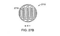
プロテーゼは、管状の本体の少なくとも一部に結合されたカバーをさらに備えることができる。カバーは、ePTFEなどのポリマーから作られた膨張可能な部材を含むことができる。 The prosthesis can further comprise a cover coupled to at least a portion of the tubular body. The cover can include an inflatable member made from a polymer such as ePTFE.
第1、第2、または中央セクション中のコネクタの少なくとも1つは、細長く延びるテーパが付けられたストラットを備えることができる。コネクタはまた、山形状の形を有するストラットを含むことができる。ストラットの最も広い幅は、山形の頂点における幅とすることができる。コネクタは、プロテーゼが、キンクを形成することなく、0.2インチ(0.508cm)以上の半径を有する湾曲部へと形成されることを可能にする。キンクは、拡大された形態における管状のプロテーゼの直径の50%未満の、拡大された形態における直径を有する管状のプロテーゼの収縮した領域を備えることができる。キンクはまた、収縮していない横断面面積の50%未満の横断面面積を有する管状のプロテーゼの収縮した領域を備えることもできる。第1、第2、または中央セクション中のコネクタの少なくとも1つは、山形状のパターンを形成するストラットを含むことができ、その場合、ストラットは、山形が収縮するのを阻止するように適合された止め要素をさらに備える。止め要素は、ストラットの第1の隆起させた領域、およびストラットの第2の隆起させた領域を備えることができる。第1および第2の隆起させた領域は、山形の両側に配置することができる。 At least one of the connectors in the first, second, or central section can comprise an elongated taper strut. The connector can also include struts having a chevron shape. The widest width of the strut can be the width at the apex of the chevron. The connector allows the prosthesis to be formed into a bend having a radius of 0.2 inches (0.508 cm) or greater without forming a kink. The kink can comprise a contracted region of the tubular prosthesis having a diameter in the expanded configuration that is less than 50% of the diameter of the tubular prosthesis in the expanded configuration. The kink can also comprise a contracted region of a tubular prosthesis having a cross-sectional area of less than 50% of the non-contracted cross-sectional area. At least one of the connectors in the first, second, or central section can include struts that form a chevron pattern, where the struts are adapted to prevent the chevron from contracting. It further comprises a stop element. The stop element can comprise a first raised region of struts and a second raised region of struts. The first and second raised regions can be located on both sides of the chevron.
本発明の他の態様では、血管中の動脈瘤を治療するための方法は、プロテーゼを結合させたデリバリ・カテーテルを提供するステップを含む。プロテーゼは、収縮した形態から半径方向に拡大された形態へと拡大可能な管状の本体を備える。管状の本体は、ある合計長を有しており、第1のセクション、第2のセクション、およびその間に配置される中央セクションを備え、各セクションは、ある長手方向長さを有する。収縮させたプロテーゼは、動脈瘤の方向に送られ、またプロテーゼを半径方向に拡大することにより、第1セクション、中央セクション、および第2のセクションのそれぞれがある拡大された直径へと拡大される。中央セクションは、第1のセクションの拡大された直径、および第2のセクションの拡大された直径とは異なる直径に拡大される。半径方向に拡大した形態における管状の本体の合計長は、収縮した形態における管状の本体の合計長の少なくとも95%であることが好ましく、いくつかの実施形態では、少なくとも98%であることがさらに好ましい。デリバリ・カテーテルは、次いで、動脈瘤から除去される。 In another aspect of the invention, a method for treating an aneurysm in a blood vessel includes providing a delivery catheter having a prosthesis attached thereto. The prosthesis includes a tubular body that is expandable from a contracted configuration to a radially expanded configuration. The tubular body has a total length and comprises a first section, a second section, and a central section disposed therebetween, each section having a longitudinal length. The contracted prosthesis is sent in the direction of the aneurysm and is expanded to an enlarged diameter with each of the first section, the central section, and the second section by radially expanding the prosthesis. . The central section is expanded to a diameter different from the expanded diameter of the first section and the expanded diameter of the second section. The total length of the tubular body in the radially expanded configuration is preferably at least 95% of the total length of the tubular body in the contracted configuration, and in some embodiments it is further at least 98%. preferable. The delivery catheter is then removed from the aneurysm.
プロテーゼを半径方向に拡大するステップは、中央セクションを半径方向に拡大する前に、第1のセクションを半径方向に拡大するステップと、第2のセクションを半径方向に拡大する前に、中央セクションを半径方向に拡大するステップとを含むことができる。第1のセクションの拡大された直径は、中央セクションの拡大した直径よりも大きくすることができ、また中央セクションの拡大した直径は、第2のセクションの拡大した直径よりも大きくすることができる。プロテーゼを半径方向に拡大するステップは、第1のセクションの外側表面と、中央セクションの外側表面の間で段付き領域を形成するステップを含むことができる。段付き領域はまた、中央セクションの外側表面と、第2のセクションの外側表面の間とすることもできる。プロテーゼを半径方向に拡大するステップは、第1のセクションから、中央セクションおよび第2のセクションへと実質的に滑らかなテーパを形成するステップを含むことができる。 The step of radially expanding the prosthesis includes the step of radially expanding the first section before radially expanding the central section and the step of expanding the central section before radially expanding the second section. Radially expanding step. The enlarged diameter of the first section can be larger than the enlarged diameter of the central section, and the enlarged diameter of the central section can be larger than the enlarged diameter of the second section. The step of radially expanding the prosthesis can include forming a stepped region between the outer surface of the first section and the outer surface of the central section. The stepped region can also be between the outer surface of the central section and the outer surface of the second section. The step of radially expanding the prosthesis may include forming a substantially smooth taper from the first section to the central section and the second section.
プロテーゼを半径方向に拡大するステップは、第1のセクションおよび第2のセクションを半径方向に拡大した後に、中央セクションを半径方向に拡大するステップを含むことができる。プロテーゼを半径方向に拡大するステップはまた、中央セクションを半径方向に拡大する前に、第1のセクションおよび第2のセクションを半径方向に拡大するステップを含むことができる。いくつかの実施形態では、プロテーゼを半径方向に拡大するステップは、第1のセクションまたは第2のセクションの少なくとも一方を末広がりにするステップを含むことができるが、一方、他の実施形態では、プロテーゼを半径方向に拡大するステップは、第1のセクションおよび中央セクションを半径方向に拡大した後に、第2のセクションを半径方向に拡大するステップを含む。さらに他の実施形態では、管状の本体は、中央セクションと第2のセクションの間に配置できる第4のセクションをさらに備えることができる。プロテーゼを半径方向に拡大するステップは、第2のセクションおよび第4のセクションを半径方向に拡大する前に、第1のセクションおよび中央セクションを半径方向に拡大するステップを含むことができる。さらに他の実施形態では、プロテーゼを半径方向に拡大するステップは、第1のセクションおよび第2のセクションを共に半径方向に拡大する前に、中央セクションを半径方向に拡大するステップを含むことができる。 The step of radially expanding the prosthesis may include the step of radially expanding the central section after the first section and the second section are radially expanded. The step of radially expanding the prosthesis may also include the step of radially expanding the first section and the second section before radially expanding the central section. In some embodiments, radially expanding the prosthesis can include diverging at least one of the first section or the second section, while in other embodiments, the prosthesis Expanding the second section radially includes expanding the first section and the central section in the radial direction and then expanding the second section in the radial direction. In still other embodiments, the tubular body can further comprise a fourth section that can be disposed between the central section and the second section. Radially expanding the prosthesis can include radially expanding the first section and the central section prior to radially expanding the second section and the fourth section. In still other embodiments, radially expanding the prosthesis can include radially expanding the central section before radially expanding the first section and the second section together. .
プロテーゼを半径方向に拡大するステップは、第1の直径に対する第2の直径の比が、1より大きく、かつ約15未満となりうるように、収縮した形態における第1の直径から、半径方向に拡大した形態における第2の直径へとプロテーゼを拡大するステップを含むことができる。さらに、プロテーゼを半径方向に拡大するステップは、デリバリ・カテーテル上に配置されたバルーンなどの拡大可能な部材を拡大するステップを含むことができる。 The step of radially expanding the prosthesis radially expands from the first diameter in the contracted configuration such that the ratio of the second diameter to the first diameter is greater than 1 and less than about 15. Expanding the prosthesis to a second diameter in the configured configuration. Further, radially expanding the prosthesis may include expanding an expandable member, such as a balloon disposed on the delivery catheter.
管状のプロテーゼは、半径方向に拡大した形態で、ある直径を有することができ、また方法はさらに、外部から受ける約60mmHgから約1000mmHgの間の半径方向差圧が与えられたとき、管状のプロテーゼの少なくとも一部に沿って、半径方向に拡大された直径の少なくとも50%を維持するステップを含むことができる。時には、管状のプロテーゼ中に、湾曲部が形成される可能性がある。湾曲部は、キンクを形成することなく、0.2インチ(0.508cm)以上の半径を有することができる。キンクは、拡大された形態における管状のプロテーゼの直径の50%未満の、拡大された形態における直径を有する管状のプロテーゼの収縮した領域を備えることができる。キンクはまた、収縮していない横断面面積の50%未満の横断面面積を有する管状のプロテーゼの収縮した領域を備えることができる。 The tubular prosthesis can have a diameter in a radially expanded configuration, and the method can further include a tubular prosthesis when subjected to a radial differential pressure between about 60 mmHg and about 1000 mmHg received from the outside. Maintaining at least 50% of the radially expanded diameter along at least a portion thereof. Sometimes curved portions can be formed in a tubular prosthesis. The curved portion can have a radius of 0.2 inches (0.508 cm) or more without forming a kink. The kink can comprise a contracted region of the tubular prosthesis having a diameter in the expanded configuration that is less than 50% of the diameter of the tubular prosthesis in the expanded configuration. The kink can also comprise a contracted region of a tubular prosthesis having a cross-sectional area of less than 50% of the non-contracted cross-sectional area.
プロテーゼは、管状の本体と結合された膨張可能な部材をさらに備えることができ、また方法は、膨張可能な部材を膨張させるステップをさらに含むことができる。膨張可能な部材を、60〜1000mmHgの差圧へと原位置で硬化可能なポリマーを用いて充填することができるが、拡大されたプロテーゼは、なお、膨張可能な部材の充填中、および硬化中に、そこを通る血液灌流を可能にすることができる。膨張可能な部材は膨張して、動脈瘤の壁と係合することができる。時には、膨張可能な部材を、原位置で硬化可能なポリマーと共に膨張させることもできる。膨張させるステップはさらに、膨張可能な部材および管状の本体を動脈瘤と固定するステップを含むことができる。 The prosthesis can further comprise an inflatable member coupled with the tubular body, and the method can further comprise inflating the inflatable member. The expandable member can be filled with a polymer that can be cured in situ to a differential pressure of 60-1000 mmHg, but the expanded prosthesis is still filling and expanding the expandable member. In addition, blood perfusion therethrough can be enabled. The expandable member can expand and engage the aneurysm wall. Sometimes the expandable member can be expanded with a polymer that is curable in situ. Inflating can further include securing the inflatable member and the tubular body with the aneurysm.
プロテーゼの第1のセクションは、動脈瘤の上流に配置することができ、また中央セクションは、動脈瘤中に配置することができる。第2のセクションは、動脈瘤の下流に配置することができる。動脈瘤は、腹部大動脈を含む大動脈の任意の部分に位置するはずである。デリバリ・カテーテルは、その上に配置された規制部材を備えることができ、プロテーゼを半径方向に拡大するステップは、管状のプロテーゼから、その規制部材を除去するステップを含むことができる。デリバリ・カテーテルを除去するステップは、デリバリ・カテーテル上に配置された膨張可能な部材を収縮させるステップを含む。プロテーゼは、それに結合された治療薬を備えることができ、また方法は、治療薬を制御された方法で投与するステップをさらに含むことができる。 The first section of the prosthesis can be placed upstream of the aneurysm and the central section can be placed in the aneurysm. The second section can be placed downstream of the aneurysm. An aneurysm should be located in any part of the aorta, including the abdominal aorta. The delivery catheter can include a restricting member disposed thereon, and radially expanding the prosthesis can include removing the restricting member from the tubular prosthesis. Removing the delivery catheter includes deflating an inflatable member disposed on the delivery catheter. The prosthesis can comprise a therapeutic agent coupled thereto, and the method can further comprise administering the therapeutic agent in a controlled manner.
本発明の他の態様では、長手方向軸、および軸方向に変化可能な特性を有する管状のプロテーゼを製作する方法は、管状のプロテーゼの第1の領域を製作するステップを含み、第1の領域は、第1の組の材料特性を有する。本方法はまた、管状のプロテーゼの第2の領域を製作するステップを含み、第2の領域は、第2の組の材料特性を有する。さらに、本方法は、管状のプロテーゼの第3の領域を製作するステップを含み、第3の領域は、第3の組の材料特性を有する。第1の領域、第2の領域、および第3の領域は、長手方向軸に沿って軸方向に整列され、また第1の組の材料特性は、第2の組の材料特性とは異なる。第2の組の材料特性は、第3の組の材料特性とは異なる。第1の領域は、管状のプロテーゼが半径方向に拡大されるとき、第2または第3の領域の前に半径方向に拡大する。 In another aspect of the invention, a method of fabricating a tubular prosthesis having a longitudinal axis and an axially variable property includes fabricating a first region of the tubular prosthesis, the first region Has a first set of material properties. The method also includes fabricating a second region of the tubular prosthesis, the second region having a second set of material properties. In addition, the method includes fabricating a third region of the tubular prosthesis, the third region having a third set of material properties. The first region, the second region, and the third region are axially aligned along the longitudinal axis, and the first set of material properties is different from the second set of material properties. The second set of material properties is different from the third set of material properties. The first region expands radially before the second or third region when the tubular prosthesis is expanded radially.
第1の領域、第2の領域、または第3の領域を製作するステップは、管、または実質的に平坦なシート材の放電加工、レーザ切断、または光化学エッチングを含むことができる。第2の領域は、プロテーゼの第1の領域と第3の領域の間に配置することができる。 The step of fabricating the first region, the second region, or the third region can include electrical discharge machining, laser cutting, or photochemical etching of a tube or a substantially flat sheet material. The second region can be disposed between the first region and the third region of the prosthesis.
本方法は、管状のプロテーゼの第4の領域を作成するステップをさらに含むことができ、第4の領域は、第4の組の材料特性を有する。第4の組の材料特性は、第1の組の材料特性とは異なることができる。さらに、第4の領域は、展開されたとき、管状のプロテーゼの第1の領域の後に、半径方向に拡大することができる。第1、第2、第3、または第4の組の材料特性は、ストラット長、ストラット幅、ストラットの厚さ、セル当たりのストラット数、コネクタ半径、コネクタの厚さ、コネクタの幾何形状、材料の焼戻し硬度、材料の強度、およびそれらの組合せからなる群から選択された少なくとも1つの機械的性質を含むことができる。 The method can further include creating a fourth region of the tubular prosthesis, the fourth region having a fourth set of material properties. The fourth set of material properties may be different from the first set of material properties. Furthermore, the fourth region can expand radially after the first region of the tubular prosthesis when deployed. The first, second, third, or fourth set of material properties includes strut length, strut width, strut thickness, number of struts per cell, connector radius, connector thickness, connector geometry, material At least one mechanical property selected from the group consisting of tempering hardness, material strength, and combinations thereof.
これらの、および他の実施形態が、添付の図面と関連する以下の記述でさらに詳細に述べられる。 These and other embodiments are described in further detail in the following description, taken in conjunction with the accompanying drawings.
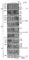
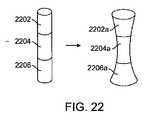
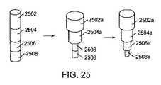
本発明の原理による図1は、3つの別個の領域を有する管状のプロテーゼ100の例示的な実施形態を示している。プロテーゼ100は、動脈瘤の治療において、ポリマーまたは織物のカバーと共に使用できる植込み可能な内部フレームを表す。プロテーゼは、単独で使用することができるが、それに隣接して配置された他のプロテーゼと組み合わせて使用することもできる。プロテーゼ100は、頸部領域110、本体領域120、および腸骨領域130を有する。各セクションは、コネクタと共に結合されるいくつかの管状リングからなり、3つの領域はまた、コネクタと共に結合される。各領域中の管状リングは、その長さに沿って軸方向にプロテーゼ100の機械的性質を変化させるように、異なる開放セル型(open cell)幾何形状を有する。 FIG. 1, in accordance with the principles of the present invention, illustrates an exemplary embodiment of a
図1で示され、また図2で拡大された頸部領域110は、近位セクションとも呼ばれるが、それは、動脈瘤に対して近位に配置されることが多いからである(本出願における近位とは、患者の心臓に最も近い方向を指すことになる)。近位セクション110は、2つの管状リング140を備えるが、リング数は、それより多いことも少ないこともありうる。各管状リング140は、円周で一連のピーク部144および谷部146を形成するように共に結合された複数の軸方向に方向付けられたストラット142からなる。近位領域中のストラット142は、本体領域120におけるストラット162、または腸骨領域130におけるストラット182よりも長い。近位セクション110で最も長いストラット長を有することは、近位セクション110が、プロテーゼ100の残りの部分よりもより大きい直径に拡大できることを保証する。プロテーゼ100は、最高で約15対1の拡大比を有することができる。近位セクション110における大きな拡大比により、このセクションは、手技後の調整(例えば、手技後の膨張またはトラッキング)中にさらに拡大させることを可能にする。さらに、近位セクション110で最長のストラット長を有することは、プロテーゼのこの部分が、展開中に、中央セクション120および遠位セクション130に対して最初に半径方向に拡大し、かつ開くことを保証する。 The
半径方向に拡大された形態において、近位セクション110は、ストラットの極限引張強度を超えることになる、または血管中に植え込まれている間の周期的な疲労の影響に耐えるためのプロテーゼ100の能力を損なう過度の応力をピーク部144および谷部146で生ずることなく適切な半径方向強度を与えうるように、ストラット長は最適化される。典型的なストラット長は、約2mmから約8mmの長さの範囲とすることができ、好ましい実施形態では、約3mmから約5mmの長さの範囲とすることができる。 In a radially expanded configuration, the
管状リング140を所望の直径にまで半径方向に拡大させることをなお可能にしながら、高い半径方向強度を与えるように、ストラット142の長さを最適化された状態に保つことは、ピーク部144の頂点および谷部146の底部で大量の歪みを生ずることになる。この歪みは、ストラット142の材料の性質を超えて障害を生ずるおそれがある。この課題を克服するために、ピーク部144の頂点および谷部146の底部におけるストラット142の幅は、歪みを低減するために、ストラット142の残りの部分よりも広くすることができる。さらに、ストラットの幅は、注意して調整する必要があるが、それは、過度のストラット幅は、ストラットのピーク部および谷部でより小さい曲率半径を生ずることになり、それは、次いで、望ましくない応力上昇を生ずることになり、さらにストラット142中により多くの材料を有することはまた、挿入中に低い外形へと縮めるべき管状リング140の機能を妨害するからである。したがって、好ましい実施形態ではストラット142にはテーパが付けられる。ストラット142は、管状リング140の円周の中心線にて最も細く、ピーク部144または谷部146へと延びるにつれて外側方向にテーパが付けられている。ストラット142は、ピーク部144の頂点および谷部146の底部で最も太い。ストラット幅は、約0.1mmから約1mmの範囲とすることができ、また好ましい実施形態では、約0.2mmから約0.5mmの範囲とすることができる。1つの管状リング内のストラットの最も幅の広いセクションと、最も狭いセクションの間の比として定義されるストラット幅比は、約1.1から約4の範囲とすることができ、また好ましい実施形態では、約1.5から約2.5の範囲とすることができる。 Keeping the length of the
軸方向に延びるストラット150、152を有するコネクタ148は、隣接する管状リング140を共に結合する。隣接する管状リング140のピーク部144は、互いに位相がずれているので、一方の管状リング140中の各ピーク部144は、隣接する管状リング140中の谷部146と結合される。軸方向ストラット150、152は、プロテーゼ100の長手方向軸に対して実質的に平行である。一方のリング140において、ピーク部144から谷部146へと延びる長さを有する軸方向ストラット150、152の長い長さにより、隣接する管状リングには、他の市販されているプロテーゼで一般的に見られる短いコネクタよりもより大きな可撓性が得られることになる。コネクタ148は、「v」または「山形」状に形成されており、また一方の軸方向ストラット150は、ピーク部144の内側半径に結合されるが、反対側の軸方向ストラット152は、隣接する管状リング140中の谷部146の内側半径に結合される。コネクタのこの構成は、半径方向に拡大中の近位セクションの短縮化が最小となることを保証できるようにする。好ましい実施形態では、短縮化は約5%以下であり、より好ましい実施形態では、短縮化は約2%以下である。コネクタ148の幅は、約0.025mmから約0.3mmの範囲とすることができ、また好ましい実施形態では、幅は、約0.075mmから約0.2mmの範囲とすることができる。固定化されたコネクタ幅を有する管状リング内のストラット幅に対するコネクタ幅の比は、約0.1から約1.25の範囲とすることができ、また好ましい実施形態では、その比は、約0.2から約0.5の範囲とすることができる。コネクタ幅が、テーパまたは他の幾何形状により変化する実施形態では、この比は、約0.65から約1.0まで変化することができる。 A
図1における本体領域120はまた、中央セクションとも呼ばれ、4つの管状リング160を備えているが、リング数は、必要に応じて変えることができる。中央セクション120の最も近位の領域は、山形の形状をしたコネクタ172を介して、近位セクション110における最も遠位のリングと結合される。コネクタ172の一方の端部は、ピーク部164の外側半径に結合され、または他方の端部は、ピーク部144の内側半径と結合される。各管状リング160は、円周上に一連のピーク部164および谷部166を形成するように共に結合された複数の軸方向に方向付けられたストラット162からなる。中央セクション120におけるストラット162は、近位セクション110のストラット142よりも短いが、ストラット162は、プロテーゼ100の腸骨領域130中のストラット182よりもさらに長く、したがって、中央セクション120は、近位セクション110が拡大を開始した後に、ただし、腸骨領域130が拡大する前に拡大を開始する。半径方向に拡大された形態において、中央セクションは、ストラットの極限引張強度を超えることになる、または血管中に植え込まれている間の周期的な疲労の影響に耐えるためのプロテーゼの能力を損なう過度の応力をピーク部および谷部で生ずることなく動脈瘤の嚢部分に配置されることの多い中央セクション120における適切な半径方向強度を与えうるように、ストラット長は最適化される。近位領域におけるストラット長に対する本体領域におけるストラット長の比は、約0.3から約1.0の範囲とすることができ、また好ましい実施形態では、約0.7から約0.9の範囲とすることができる。 The
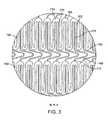
ちょうど近位セクション110におけるものと同様に、ストラット長162は、高い半径方向強度を与えるように最適化されるが、ピーク部164および谷部166を過度に歪ませることなく、管状リング160は、なお、所望の直径へと半径方向に拡大することが可能である。したがって、好ましい実施形態では、ストラット162にはテーパが付けられる。ストラット162は、管状リング160の円周における中心線で最も細く、ピーク部164または谷部166へと延びるにつれて外側方向にテーパが付けられる。ストラット162は、ピーク部164の頂点で、かつ谷部166の底部で最も太く、これは図3で示されている。本体領域におけるストラット幅は、近位セクションにおけるストラット長に関して前に述べたものと同様である。図4は、有限要素解析モデリング技法を用いて計算された、拡大したプロテーゼ100におけるピーク部164の周囲の応力分布を示す。 Just as in the
軸方向に延びるストラット170、172を有するコネクタ168は、隣接する管状リング160を共に結合する。中央セクション120では、隣接する管状リング上のピーク部164は、互いに同位相であり、したがって、一方の管状リング160における各ピーク部164は、隣接する管状リング160のピーク部164と結合される。しかし、近位セクション110とは異なり、中央セクションでは、一方の軸方向に延びるストラット170は、他方の軸方向に延びるストラット172よりもかなり長く、したがって、より長いストラット170は、ピーク部164の内側半径に結合され、より短いストラット172は、隣接する管状リング160のピーク部164の外側半径の頂点に結合される。より長いストラット170は十分細いので、隣接する管状リング160上の隣接するストラット162間で入れ子にすることができ、これは、収縮した形態にあるとき、プロテーゼの外形を縮小することを助ける。軸方向に延びるストラット170は、主要な耐負荷部材ではないので、ストラット162よりもかなり細くすることができる。軸方向に延びるストラット170、172はまた、プロテーゼ100の長手方向軸と実質的に平行であり、またコネクタ168は、「v」または山形状に形成される。コネクタ168の構成は、隣接する管状リング160の中心線間で相対的な動きがほとんどないか、全くないことを保証し、したがって、中央セクション120の短縮化は、半径方向の拡大中に最小となる。この実施形態では、短縮化は約2%以下である。図5は、プロテーゼ100の中央セクション120におけるコネクタ168を示している。コネクタ168の寸法は、近位セクションにおけるコネクタ148に関して前に述べたものと同様である。 A
図1はまた、遠位セクションとも呼ばれるプロテーゼ100の腸骨領域130を示す。遠位セクション130は、山形に形成されたコネクタ171を介して中央セクション120に結合される。コネクタ171は、ピーク部184の外側半径と、ピーク部164の内側半径とに結合される。遠位セクション130は、4つの管状リング180を備えるが、この数は、必要に応じて修正することができる。各管状リング180は、円周で一連のピーク部184および谷部186を形成するように、共に結合された複数の軸方向に方向付けられたストラット182を備える。遠位セクション130におけるストラット182は、近位セクションのストラット142、および中央セクションのストラット162と比較して、プロテーゼ100中で最も短いストラットである。ストラット182は、最も短いので、遠位セクション130は、展開中に半径方向に拡大するプロテーゼ100のうちの最後のセクションとなる。さらに、遠位セクション130における最短のストラットは、動脈瘤に対して遠位に配置されることが多く、かつ大動脈中に配置できる近位セクション110の直径と比較して、直径がかなり小さい腸骨動脈中もしくは近傍に配置されることが多い遠位セクション130の円周にわたって、より一様に拡大することを保証できるようにする。遠位セクション130により長いストラットを使用することは、血管の直径に一致させるために、いくつかのストラットが開くだけとなるはずであり、この結果は、プロテーゼ100を拡大するために使用される拡大可能なバルーンが一様に畳まれない場合、さらに悪化させるおそれがある。このような例では、プロテーゼ100は、バルーンの折り畳み部が最初に開くいずれかの側に対して偏倚して拡大することになり、ストラットは、その側で広く開くことになるが、一方、プロテーゼの反対側のストラットは、実質的に閉じたままとなる。示したように、より短いストラットを使用することは、不均一な拡大に対する遠位セクション130の感度を低下させる。さらに、遠位セクション130の短いストラット182の長さにより、直線長さ当たりのリング数、またはピッチが、プロテーゼ100の他のセクションと比較して増加する。この特徴は、遠位セクション130が、腸骨動脈中でしばしば見られる血管中のきつい湾曲部に適合することを可能にするさらなる利点を有する。本体領域におけるストラット長に対する遠位端におけるストラット長の比は、約0.3から約1.0の範囲とすることができ、また好ましい実施形態では、約0.7から0.9の範囲とすることができる。 FIG. 1 also shows the iliac region 130 of the
遠位セクション130におけるストラット182にはまた、近位セクションのストラット142、および中央セクションのストラット162と同様にテーパを付けられる。ストラット182は、管状リング180の円周の中心線で最も細く、幅には、ピーク部184または谷部186へと延びるにつれて外側方向にテーパが付けられる。ストラット182は、したがって、ピーク部184の頂点で、かつ谷部186の底部で最も太い。ストラット182の幅は、プロテーゼの本体セクションおよび近位セクションにおけるストラット162および142に関して前に述べたものと同様である。 The
軸方向に延びるストラット190、192を有するコネクタ188は、隣接する管状リング180を共に結合する。遠位セクション130では、隣接する管状リング上のピーク部184が互いに同位相であり、したがって、一方の管状リング180における各ピーク部184は、隣接する管状リング180におけるピーク部180と結合される。コネクタ188は、他方の軸方向に延びるストラット192よりもかなり長い一方の軸方向に延びるストラット190を有しており、より長いストラット190は、ピーク部184の内側半径に結合されるが、一方、より短いストラット192は、隣接する管状リング180におけるピーク部184の外側半径に結合される。中央セクション120と同様に、より長いストラット190は十分細いので、一方の管状リング180における隣接するストラット182間で入れ子にすることができ、これは、収縮した形態におけるプロテーゼ100の外形を縮小させることを助ける。さらに、軸方向に延びるストラット190は、主要な耐負荷部材ではないので、ストラット182よりもかなり細くすることができる。軸方向に延びるストラット190、192はまた、プロテーゼ100の長手方向軸に対して実質的に平行であり、またコネクタ188は、「v」または山形状に形成される。コネクタ188の構成は、隣接する管状リング180の中心線間で相対的な動きがほとんどない、または全くなく、したがって、遠位セクション130の短縮化が半径方向の拡大中に最小となることを保証する。この実施形態では、短縮化は約5%以下であり、より好ましくは、2%以下である。プロテーゼの3つのセクションのそれぞれにおける短縮化が約5%以下に、より好ましくは約2%以下に制限されるので、拡大された形態における全体の人口装具長さは、拡大されていないプロテーゼ長さの約95%以上となり、より好ましくは、約98%以上となる。図5は、プロテーゼ100の遠位セクション130の拡大図である。さらに、プロテーゼ100の遠位セクション130における最も遠位の管状リング194が、図7に示されている。管状リング194は、遠位セクション130における最後のリングであるため、ピーク部184の外側半径に結合されたコネクタ188を有するだけである。コネクタの幅は、プロテーゼの近位領域および本体領域におけるコネクタに関して上記で論じたものと同様である。 A
プロテーゼ100のすべての領域におけるストラットの厚さは、約0.2から約1.0mmの範囲とすることができるが、好ましい実施形態では、約0.3mmから約0.4mmの範囲とすることができる。プロテーゼ100のすべての領域のためのストラット幅に対するストラットの厚さの間のアスペクト比は、したがって、約0.3から約3の範囲とすることができるが、好ましい実施形態では、ストラットの最も幅が広い点における約0.75から、ストラットの最も幅が狭い点における約2までの範囲とすることができる。 The strut thickness in all regions of the
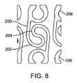
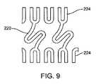
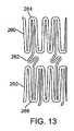
図1の例示的な実施形態は、プロテーゼがキンクに抗するのを助ける利点を有する「v」形、または山形に形成されたコネクタを説明している。山形に形成されたコネクタを使用するこの、または他の実施形態では、プロテーゼを、よじれることなく、0.2インチ(0.508cm)以上の半径を有する湾曲部へと曲げることができる。キンクは、拡大された形態におけるプロテーゼ直径の50%未満の直径を有する拡大された形態におけるプロテーゼの収縮した部分と定義される。キンクはまた、収縮していない横断面面積の50%未満の横断面面積を有する管状のプロテーゼの収縮した領域を含むこともできる。さらに、当業者であれば、多くの他のコネクタ幾何形状も使用できることが理解されよう。例えば、真っ直ぐなコネクタ、またはS字状のコネクタを、当業者に知られた他のものと同様に使用することができる。図8〜13、および図16〜17は、プロテーゼの近位、中央、または遠位セクション内で使用できる、または近位−中央セクション、もしくは中央−遠位セクションを共に結合するために使用できる代替のコネクタ実施形態を示している。図8は、隣接する管状リング206を共に結合するために使用できるコネクタ200を示す。この実施形態では、コネクタ200は、互いに隣接する2つの拡大されたヘッド領域202、204を形成する弓状の形状を有する。拡大されたヘッド領域は、「陰陽」記号に類似したパターンを形成し、かつコネクタ200が、最小のピーク部応力で軸方向に拡大することを可能にする。同様に、図9は、弓状のコネクタ220が、隣接する管状リング224間で、コネクタ220の軸方向の拡大をさらに可能にするS字状の形を形成する他のコネクタ実施形態220を示している。図10は、隣接する管状リング238を共に結合するために使用されるさらに他の実施形態のコネクタ230を示す。しかし、コネクタ230は、前に述べた山形に形成されたコネクタと同様のものであり、この実施形態では、コネクタの幅は、軸方向に延びる232、234の近傍の細い領域と共にテーパが付けられている。ストラット幅は、細い領域から、ストラットが最も太い山形236の頂点まで増加する。テーパに設計することは、コネクタの軸方向強度を高めるのを助けることができるが、なお、コネクタが、軸方向に拡大することを可能にし、かつ頂点における応力を最小化することができる。図11は、ほぼ閉じたコネクタ設計を有するコネクタ実施形態を示している。図11では、コネクタ240は、狭い頸部領域と、拡大されたヘッド領域244を形成する2つの脚部246、248を有する弓状のストラットを含む。コネクタ240は、隣接する管状リング242を共に結合する。拡大されたヘッド領域244により、コネクタ240は、軸方向に拡大することを可能にし、一方、脚部246、248により形成される狭い頸部領域は、コネクタ240が圧縮時に軸方向に収縮しないようにすることを助ける。 The exemplary embodiment of FIG. 1 illustrates a “v” shaped or chevron shaped connector that has the advantage of helping the prosthesis resist kinks. In this or other embodiments using a chevron shaped connector, the prosthesis can be bent into a bend with a radius of 0.2 inches (0.508 cm) or greater without kinking. A kink is defined as a contracted portion of a prosthesis in an expanded configuration that has a diameter of less than 50% of the prosthesis diameter in the expanded configuration. The kink can also include a contracted region of a tubular prosthesis having a cross-sectional area of less than 50% of the non-contracted cross-sectional area. Further, those skilled in the art will appreciate that many other connector geometries can be used. For example, straight connectors or S-shaped connectors can be used as well as others known to those skilled in the art. FIGS. 8-13, and FIGS. 16-17 are alternatives that can be used in the proximal, central, or distal section of the prosthesis, or that can be used to join the proximal-central section, or the central-distal section together 1 illustrates a connector embodiment. FIG. 8 shows a
他のコネクタ構成もまた、プロテーゼの短縮化を制御するために使用することができる。例えば、図12は、互いに位相のずれたピーク部を有し、かつ弓状のコネクタ252を共に結合する2つの隣接する管状リングを示す。コネクタ252の両端は、隣接する管状リング上のピーク部254、256の外側半径に接続される。この構成により、半径方向に拡大中に短縮化を可能にする。図13は、隣接する位相のずれた管状リング260間のS字状に形成されたコネクタ262が、一方のピーク部264の内側半径に結合され、また反対側の端部が、谷部266の内側半径に結合される実施形態を示し、それにより、半径方向に拡大中に伸張されることを可能にする実施形態を示している。これらのコネクタの様々な組合せは、2つのプロテーゼを互いに突き合わせるときに必要となりうる、一方の側を長くし、反対側を短くするプロテーゼを提供するために使用することができる。図17は、2つの突出部904、906を、山形の両側に有し、それにより、止め要素を形成する山形に形成されたコネクタ902を示す。山形は、外方向に拡大することができるが、圧縮時の動きは制限され、これは、プロテーゼの拡大中の短縮化を低減するのに有用である。図16は、隣接する管状リングを共に結合する山形に形成されたコネクタ802を示す。テーパを付けたストラット802に加えて、コネクタは、コネクタ802のステム804が、コネクタ802の軸方向部分の残りよりも広くなるように、かつ山形806の頂点が、コネクタ802の最も広い部分であるようにテーパが付けられる。コネクタ804をより広く作ることにより、より堅くなり、これは、半径方向に拡大中に短縮化すること、ならびにプロテーゼの曲げおよび座屈することを低減するのを助ける。 Other connector configurations can also be used to control prosthesis shortening. For example, FIG. 12 shows two adjacent tubular rings that have peaks that are out of phase with each other and that connect
図1の実施形態では、近位セクションと中央セクションの間の遷移、ならびに中央セクションと遠位セクションの間の遷移は、幾分、急峻である。ストラット長が、セクションからセクションへと、ある長さからより短い長さへと変化している。これは、プロテーゼが拡大されたとき、段付きの領域を生ずる可能性がある。図19は、収縮した形態および拡大した形態の図1におけるものと同様のプロテーゼの概略図を示している。プロテーゼは、第1の領域1902、第2の領域1906、および中央領域1904を有しており、それぞれが、図1と同様のピーク部および谷部の幾何形状を有するが、各領域は異なるストラット長を有する。1つの領域から次の領域へとストラット長が劇的に変化する場合、段付き領域1908が、拡大された第1の領域1902a、第2の領域1906a、および中央領域1906bの間で形成される可能性がある。段付き領域を滑らかにすることが望ましいはずであり、また解剖学的構造によく一致しかつ血流に対してより滑らかな経路を設けるために、より滑らかにし、テーパを付けた拡大プロテーゼを提供することは望ましいはずである。したがって、プロテーゼを、ストラット長の変化、ならびに対応する性能特性の変化が、より漸進的であるように変更することができるが、これは、いくつかの隣接する管状リングのコースにわたりストラット長を徐々に変化させることにより達成することができ、したがって、近位、中央、および遠位セクションの間に別個の分割線がなくなる。図20は、図1と同様のプロテーゼであり、同様のピーク部および谷部の幾何形状を有するプロテーゼの概略図を示す。図20のプロテーゼは、収縮した形態で、第1の領域2002、第2の領域2006、および中央領域2004を有しており、また第1の領域2002a、第2の領域2006a、および中央領域2004aが拡大されたとき、結果として得られるプロテーゼの滑らかなテーパを有する。図20はまた、図1に関して上記で述べた同様のピーク部および谷部の幾何形状を含む。図14は、段付きの形状ではなく、よりテーパの付けられた拡大された形状を生成することになる、プロテーゼの領域間のさらに漸進的な遷移を有する管状のプロテーゼの例示的な実施形態を示す。図14のプロテーゼは、平坦に示されており、見やすくするために展開されている。 In the embodiment of FIG. 1, the transition between the proximal section and the central section, and the transition between the central section and the distal section are somewhat steep. The strut length changes from section to section, from one length to a shorter length. This can result in a stepped area when the prosthesis is enlarged. FIG. 19 shows a schematic view of a prosthesis similar to that in FIG. 1 in a contracted and expanded configuration. The prosthesis has a
図14で見られるプロテーゼ300は、図1の実施形態と同様のものである。それは、3つの別個の領域、すなわち、近位セクション310、中央セクション320、および遠位セクション330を有する。図14と図1の実施形態の間の主な差は、近位セクション310におけるストラット長、およびコネクタの構成である。プロテーゼ300はまた、動脈瘤の治療におけるポリマーまたは織物カバーと共に使用することのできる植込み可能な内部フレームである。プロテーゼ300は、単独で使用することができるが、それに隣接して配置された他のプロテーゼと組み合わせて使用することもできる。 The
近位セクション310は、2つの隣接する管状リング340、350を備えているが、管状リングの数は、多くすることも少なくすることもできる。各管状リング340、350は、円周で一連のピーク部344および谷部346を形成するように共に結合される複数の軸方向に方向付けられたストラット342、352からなる。ストラット342は、ストラット352よりも長く、またストラット342、352は共に、プロテーゼ300の中央セクション320におけるストラット362、および遠位セクション330のストラット382よりも長い。したがって、管状リング340は、プロテーゼ300中の他のリングよりも拡大するために必要とする力は少ないので、リング340は、最初に拡大を開始し、続いて、リング350が開始し、次いで、中央セクション320および遠位セクション330のリングが拡大を開始する。さらに、管状リング340は、プロテーゼ300における最大の直径に拡大することができるが、それは、近位セクション340が、最大の直径を有する大動脈瘤に対して近位の領域中に植え込まれることが多いので望ましい(近位方向は、患者の心臓に最も近い方向である)。さらに、近位セクション340は、手技後の調整(例えば、手技後の膨張または「トラッキング」)において、さらに拡大することができる。近位セクションにおけるストラット長は、前に述べた図1の実施形態における近位セクションのストラットのものと同様であり、したがって、プロテーゼ300の拡大比は、図1の実施形態に関して前に論じたものと同様である。 The
ストラット342および352はまた、ストラットの最も細い部分が、管状リング340、350の円周の中心線であるように、テーパが付けられる。幅は、ピーク部344または谷部346へと延びるにつれて外方向にテーパが付けられる。ストラット342および352は、したがって、ピーク部344の頂点、および谷部346の底部で最も太い。ストラット幅は、図1の実施形態に関して開示された近位セクションのストラット幅のものと同様である。
軸方向に延びるストラット347、349を有するコネクタ348は、隣接する管状リング340、350を共に結合する。コネクタ348は、隣接する管状リング上のピーク部と谷部の間のギャップを横断するだけである従来のコネクタよりも長いが、長いコネクタ348には、より可撓性がある。図14の実施形態では、リング340、350のピーク部344は、互いに同位相であり、したがって、コネクタ348は、その両端で、隣接する管状リング340、350におけるピーク部344に結合される。コネクタ348は、一方のピーク部344の頂点の外側半径に結合される、より短い軸方向に延びるストラット347を有するが、一方、より長い軸方向に延びるストラット349は、隣接する管状リング340におけるピーク部344の内側半径に結合される。コネクタ348は、「v」または山形の形状を有しており、また軸方向に方向付けられたストラット347、349は、プロテーゼ300の長手方向軸に対して実質的に平行である。この構成は、プロテーゼ300が半径方向に拡大したとき、近位セクション310の軸方向収縮を最小化する。コネクタ寸法は、図1の実施形態に対して近位セクションのコネクタ寸法に関して述べたものと同様である。 A
中央セクション320は、4つの隣接する管状リング360を備えるが、この数は、必要に応じて変えることができる。中央セクション320の最も近位の管状リングは、山形に形成されたコネクタ371を介して近位セクション310の最も遠位の管状リングと結合される。コネクタ371の一端は、ピーク部364の外側半径に結合され、コネクタ371の反対側の端部は、ピーク部364の内側半径と結合される。各管状リング360は、円周で一連のピーク部364および谷部366を形成するように、共に結合された複数の軸方向に方向付けられたストラット362からなる。中央セクション320におけるストラット362は、近位セクション310のストラット342、352よりも短いが、なお、ストラット362は、遠位セクション330におけるストラット382よりも長い。したがって、中央セクション320は、近位セクション310が拡大を開始した後であるが、遠位セクション330が拡大する前に拡大を開始することになる。代替の実施形態では、中央セクションにおけるストラット362は、1つの管状リングから次のものへと減少する長さを有することができる。これはさらに、拡大した形態におけるプロテーゼに沿って滑らかに遷移することを促進する。したがって、近位セクションに最も近いリング中のストラット362が最も長く、また近位セクションから最も離れたリング中のストラット362が最も短く、その間のリング中のストラット長は、比例して減少する。ストラット362の長さは、その幅にテーパを付けることによって最適化され、したがって、ストラットの最も細い部分は、管状リング360の円周の中心線におけるものである。幅は、ピーク部364または谷部366へと延びるにつれて外方向にテーパが付けられる。ストラット362は、したがって、ピーク部364の頂点、および谷部366の底部で最も太くなる。ストラット寸法は、図1の実施形態で中央セクションに関連して前に述べたものと同様である。 The
軸方向に延びるストラット367、369を有するコネクタ368は、隣接する管状リング360を共に結合する。中央セクション320では、隣接する管状リング上のピーク部364は、互いに同位相であり、したがって、一方の管状リング360における各ピーク部364は、隣接する管状リング360のピーク部364と結合される。さらに、近位セクション310と同様に、一方の軸方向に延びるストラット369は、他方の軸方向に延びるストラット369よりもかなり長く、したがって、より長いストラット369は、ピーク部364の内側半径に結合され、またより短いストラット367は、隣接する管状リング360におけるピーク部364の外側半径の頂点に結合される。より長いストラット369は十分細いので、隣接する管状リング360上の隣接するストラット362間で入れ子にすることができ、これは、収縮した形態にあるとき、プロテーゼ300の外形を縮小することを助ける。軸方向に延びるストラット369は、主要な耐負荷部材ではないので、ストラット362よりもかなり細くすることができる。軸方向に延びるストラット367、369はまた、プロテーゼ300の長手方向軸に対して実質的に平行であり、またコネクタ368は、「v」または山形状に形成される。コネクタ368の構成は、隣接する管状リング360の円周の中心線間で相対的な動きがほとんどないか、全くないことを保証し、したがって、中央セクション320は、半径方向の拡大中に最小量で短縮化する。この実施形態における短縮化は、図1に関して上記で述べたものと同様である。コネクタの寸法は、図1の中央セクションのコネクタ寸法に関して前に開示したものと同様である。 A
図14はまた、プロテーゼ300の遠位領域320を示している。遠位セクション330は、山形に形成されたコネクタ371を介して中央セクションに結合される。コネクタ371は、ピーク部384の頂点の外側半径に結合され、またコネクタ371の反対側の端部は、ピーク部364の内側半径に結合される。遠位セクション330は、4つの管状リング380を備えるが、この数は、必要に応じて変えることができる。各管状リング380は、円周で一連のピーク部384および谷部386を形成するように、共に結合される複数の軸方向に方向付けられたストラット382を備える。遠位セクション330におけるストラット382は、中央セクション320のストラット362、ならびに近位セクション310のストラット352および342と比較して、プロテーゼ300中で最短のストラットである。ストラット382が最も短いので、遠位セクション330は、展開中に半径方向に拡大するプロテーゼ300の最後のセクションとなる。さらに、遠位セクション330における最短のストラットは、動脈瘤に対して遠位に、かつ大動脈中に配置できる近位セクション310の直径と比較して直径がかなり小さい腸骨動脈中もしくは近傍に配置されることが多い遠位セクション330の円周にわたり、より一様な拡大を保証できるようにする。遠位セクション330でより長いストラットを使用することは、上記で前に論じたように、血管の直径に一致させるために、いくつかのストラットが開くだけとなるはずであり、この結果は、プロテーゼ300を拡大するために使用される拡大可能なバルーンが一様に畳まれない場合、さらに悪化させるおそれがある。したがって、遠位セクション330でより短いストラットを使用することは、不均一な拡大に対する遠位セクション330の感度を低下させる。代替の実施形態では、ストラット長はまた、プロテーゼが拡大したとき、さらに良好で、滑らかな遷移を行うために、遠位領域内でリングごとに変えることができる。したがって、中央領域に最も近いリング中のストラットが最も長く、中央領域から最も離れたリング中のストラットは最も短くなり、その間に中間的な長さが存在する。ストラット382はまた、プロテーゼ300の近位セクション310および中央セクション320のストラットと同様にテーパが付けられる。ストラット382は、ストラットの最も細い部分が、管状リング380の円周における中心線にあるようにテーパが付けられる。幅は、ピーク部384または谷部386へと延びるにつれて外側方向にテーパが付けられる。ストラット382は、したがって、ピーク部384の頂点で、かつ谷部386の底部で最も太い。ストラット382の寸法は、図1で示した遠位領域ストラットと同様である。図14の実施形態のすべての領域におけるストラットの厚さおよびアスペクト比は、図1の実施形態に関して前に開示したものと同様である。短縮化、キンク抵抗など、図14で示された実施形態の他の性能特性もまた、図1を参照して述べたものと同様である。 FIG. 14 also shows the
さらに、遠位セクション330における短いストラット382長により、直線長さ当たりのリング数、またはピッチは、プロテーゼ300の他のセクションに対して増加する。この特徴は、遠位セクション330が、腸骨動脈中でしばしば見られる血管中のきつい曲がりに対してよじれることなく適合することを可能にする。 Further, due to the
コネクタ388は、軸方向に延びるストラット387、389を有しており、かつ隣接する管状リング380を共に結合する。遠位セクション330では、隣接する管状リング上のピーク部384が互いに同位相であり、したがって、一方の管状リング380における各ピーク部384は、隣接する管状リング380におけるピーク部380と結合される。コネクタ388は、他方の軸方向に延びるストラット387よりもかなり長い一方の軸方向に延びるストラット389を有しており、より長いストラット389は、ピーク部384の内側半径に結合されるが、一方、より短いストラット387は、隣接する管状リング380におけるピーク部384の外側半径に結合される。中央セクション320と同様に、より長いストラット389は十分細いので、一方の管状リング380における隣接するストラット382間で入れ子にすることができ、またこれは、収縮した形態におけるプロテーゼ300の外形を縮小することを助ける。さらに、軸方向に延びるストラット389は、主要な耐負荷部材ではないので、ストラット382よりもかなり細くすることができる。軸方向に延びるストラット387、389はまた、プロテーゼ300の長手方向軸に対して実質的に平行であり、またコネクタ388は、「v」または山形状に形成される。コネクタ388の構成は、隣接する管状リング380の円周における中心線間で相対な動きがほとんどない、または全くないことを保証し、したがって、遠位セクション330の短縮化はまた、プロテーゼの残りのものと同様である。短縮化は、したがって、プロテーゼ300の半径方向の拡大中に約2%以下である。コネクタの寸法は、図1の実施形態に関して前に開示された遠位領域のコネクタ寸法と同様である。 The
図18は、拡大された状態におけるプロテーゼ300の近位セクション310、中央セクション320、および遠位セクション330を示す。 FIG. 18 shows the
図27A〜27Cは、軸方向に変化可能な特性を有するプロテーゼのさらに他の例示的な実施形態を示している。図27Aで示す実施形態は、上記の図14で示した前の実施形態と同様であり、主な差は、リング当たりのピーク部の数と、さらにコネクタの幾何形状である。図27Aの実施形態の他の側面は、概して、図14にて上記で述べたものと同じである。例えば、リングは、隣接するリングがコネクタと共に結合される状態で、一連のピーク部および谷部を形成するように、共に接続される複数のストラットから形成される。図27Aでは、プロテーゼは、4つの領域、すなわち、頸部領域2702、テーパ領域2704、本体領域2706、および末広がり領域2708からなる。4つの領域は、動脈瘤の中であることが多いが、患者の中で半径方向に拡大するとき、プロテーゼに沿って滑らかに遷移することを可能にする。リング当たり10個のピーク部を有する図14の実施形態とは異なり、図27Aでは、各リングは8個のピーク部2714を有する。リング当たりのピーク部の数は変えることができ、他の例示的な実施形態では、リング当たり12個のピーク部を使用できることを、当業者であれば、当然、理解されよう。頸部領域セクションの第2のリングにおけるピーク部および谷部を形成する領域2710中のストラットは、より詳細に図27Bで強調表示されている。同様に、隣接するリングを共に結合している領域2712におけるコネクタが、図27Cでより詳細に強調表示される。図27Cはまた、この実施形態におけるコネクタ2716には、ピーク部の内側半径とのその接続点に向けてテーパが付けられていることを示す。 FIGS. 27A-27C illustrate yet another exemplary embodiment of a prosthesis having axially variable properties. The embodiment shown in FIG. 27A is similar to the previous embodiment shown in FIG. 14 above, the main differences being the number of peaks per ring and the connector geometry. Other aspects of the embodiment of FIG. 27A are generally the same as those described above in FIG. For example, a ring is formed from a plurality of struts that are connected together to form a series of peaks and valleys with adjacent rings joined together with a connector. In FIG. 27A, the prosthesis consists of four regions: a
図14の例示的な実施形態は、「v」形に、または山形に形成されたコネクタを示しているが、前に述べられたコネクタおよび接続点の任意のものをこの実施形態で使用することができる。さらに、管状リングは、所望に応じて、それらが互いに同位相であるように、または位相がずれるように構成することができる。したがって、本明細書で述べる機構の任意の組合せを、軸方向に変化可能な性質を有するプロテーゼで使用することができる。本明細書で開示されたプロテーゼは、単独で拡大することができるが、バルーンで拡大することもできる。単独で拡大するプロテーゼは、ニチノールなどのニッケルとチタンの合金から製作されることが多いが、バルーンで拡大可能なプロテーゼは、ステンレス鋼、コバルトとクロムの合金などから構成されることが多い。ポリマーもまた、プロテーゼを製作するために使用することができ、それは、通常、管材のレーザ切断またはEDM(放電加工)、または平坦なシート素材の光化学的エッチングにより製作される。エッチングされたシートは、次いで、管へと巻かれて、その両端部が共に溶接される。さらに、ヘパリンなどの治療薬をプロテーゼにより搬送することができ、植込み後の血栓症の危険を低減するために制御可能に投与することができる。 The exemplary embodiment of FIG. 14 shows a connector formed in a “v” shape or in a chevron shape, but any of the previously described connectors and connection points may be used in this embodiment. Can do. Furthermore, the tubular rings can be configured so that they are in phase with each other or out of phase, as desired. Thus, any combination of mechanisms described herein can be used with a prosthesis that has axially variable properties. The prosthesis disclosed herein can be expanded alone, but can also be expanded with a balloon. A prosthesis that expands independently is often made from a nickel and titanium alloy such as Nitinol, but a balloon expandable prosthesis is often composed of stainless steel, a cobalt and chromium alloy, and the like. Polymers can also be used to fabricate prostheses, which are typically fabricated by laser cutting or EDM (electric discharge machining) of tubing, or photochemical etching of flat sheet material. The etched sheet is then wound into a tube and its ends are welded together. In addition, therapeutic agents such as heparin can be delivered by the prosthesis and can be administered in a controllable manner to reduce the risk of thrombosis after implantation.
したがって、プロテーゼのセクションごとにストラット長を変化させることは、軸方向に変化可能な特性を有するプロテーゼを生成する。その場合、プロテーゼが拡大する直径および順序を制御することができる。他の例示的な実施形態は、これだけに限らないが、以下のものを含む。図21は、3セクションのプロテーゼを概略示している。収縮した形態では、プロテーゼは、第1のセクション2102、中央セクション2104、および第2のセクション2106を有する。中央セクション2104におけるストラットは、第1のセクション2102、または第2のセクション2106中のストラットよりも短く、したがって、拡大すると、第1のセクションおよび第2のセクションは、中央セクションの前に、その拡大された直径2102a、2106aへと半径方向に拡大する。中央セクション2104aはその後に拡大する。第1のセクションおよび第2のセクションにおけるストラット長は、所望の拡大された形態を得るために変えることができる。図21で、第1のセクション2102および第2のセクション2106のストラットは、ほぼ同じ長さであり、したがって、両方のセクションの拡大された直径2102a、2106aは、大体同じである。しかし、第2のセクション2106のストラット長は、第2のセクションが、第1のセクションよりも小さな直径へと拡大するように、第1のセクション2102のストラットよりも短くすることもできる。他の変形形態もまた可能である。 Thus, varying the strut length from section to section of the prosthesis creates a prosthesis having axially variable properties. In that case, the diameter and order in which the prosthesis expands can be controlled. Other exemplary embodiments include, but are not limited to: FIG. 21 schematically illustrates a three-section prosthesis. In the contracted configuration, the prosthesis has a
図22は、第1のセクション2202、中央セクション2204、および第2のセクション2206を有する拡大されていない形態の他の3セクションプロテーゼを示している。第1のセクション2202および第2のセクション2206は、拡大された形態では、プロテーゼが、末広がりの一方または両方の端部を有するように、ストラット長を各端部に向かって徐々に増加させた複数のリングを有することもできる。末広がりの端部2202aおよび2206aにより、プロテーゼは、患者の解剖学的構造により正確に一致することができ、またプロテーゼへの出入に対して滑らかに遷移させることが可能になる。これは、腸骨動脈中で使用される可能性があるなど、延長プロテーゼと連結することを容易にすることができる。末広がり領域はまた、動脈瘤からの血小板放出および塞栓形成を阻止するのを助ける。中央セクション2204aはまた、漸進的な末広がりまたはテーパを有することができ、したがって、それは、第1のセクション2202aと第2のセクション2206aの間の滑らかな遷移を提供する。 FIG. 22 illustrates another three-section prosthesis in an unexpanded form having a
図23は、さらに他の実施形態を示しており、今度は4セクションのプロテーゼである。拡大されていない形態では、4つのセクション2302、2304、2306、および2308は、概して、同様の拡大されていない直径を有する。各セクション中のストラット長を変えることは、拡大された形態を制御することを可能にする。例えば、この実施形態では、第1のセクションおよび第4のセクションにおけるストラットは、2つの残りのセクション2304、2306よりも大きくすることができ、したがって、拡大された形態では、末広がりの端部2302aおよび2308aを得ることができる。2つの残りのセクション2304a、2306aは、末広がりの端部間で滑らかな遷移を提供する。当業者であれば、所望の拡大特性を有する所望のプロテーゼ長さを提供するために、任意の数のセクションを使用できることが理解されよう。 FIG. 23 shows yet another embodiment, this time a four-section prosthesis. In the unexpanded form, the four
さらに他の実施形態では、3セクションのプロテーゼを、一方の端部が最後に開くようにストラット長を変えることにより作成することができる。それは、プロテーゼが、デリバリ中にバルーンをしっかり保持する、または抱え込むことを可能にし、プロテーゼが、デリバリ・カテーテルに対して望ましくない排出、または他の動きを行わないようにするので有利である。図24では、拡大されていないプロテーゼは、第1のセクション2402、中央セクション2404、および第2のセクション2406を有する。半径方向に拡大すると、第1のセクション2402aおよび中央セクション2404aが最初に開く。第2のセクション2406aは最後に開く。これに対する4セクションの変形形態が図25で示されている。図25では、収縮した形態のプロテーゼは、第1、第2,第3、および第4のセクション2502、2504、2506、2508を有する。最初の2つのセクション2502、2504は、他の2つのセクション2506、2508よりも長いストラットを有しており、したがって、最初の2つのセクション2502a、2504bが最初に拡大し、その後に続いて、最後の2つのセクション2506a、2508aが拡大する。この実施形態では、プロテーゼに第1のセクション2502aから最後のセクション2508aまでテーパを付けていることが示されているが、当業者であれば、各セクションにおけるストラット長を、一方または両端を末広がりにすること、中央セクションを両端部よりも大きくすることなどを含む任意の数の他の構成に調整できることが理解されよう。 In still other embodiments, a three-section prosthesis can be created by varying the strut length so that one end opens last. It is advantageous because it allows the prosthesis to hold or hold the balloon securely during delivery, and prevents the prosthesis from performing unwanted drainage or other movement on the delivery catheter. In FIG. 24, the unexpanded prosthesis has a
図26は、軸方向に変化可能なプロテーゼの他の例示的な実施形態を示す。図26では、収縮したプロテーゼは、第1のセクション2602、第2のセクション2606、および中央セクション2604を有する。中央セクション2604中のストラットは、2つの他のセクション2602、2606よりも長く、したがって、半径方向に拡大すると、中央セクション2604aが最初に拡大し、その後に続いて、2つの他のセクション2602a、2606aが拡大する。 FIG. 26 shows another exemplary embodiment of an axially changeable prosthesis. In FIG. 26, the contracted prosthesis has a
図19〜26に示された例示的な諸実施形態は、概略図である。これらの実施形態のセクションのそれぞれは、上記で前に述べた複数のリング、ストラット、およびコネクタ幾何形状のうちのいずれか、ならびに当業者に知られた他の幾何形状を有することができる。したがって、本明細書で開示された機構のいずれかを使用して、軸方向に変化可能な特性を有するプロテーゼを作成することができる。 The exemplary embodiments shown in FIGS. 19-26 are schematic. Each of these embodiment sections can have any of the ring, strut, and connector geometries previously described above, as well as other geometries known to those skilled in the art. Accordingly, any of the mechanisms disclosed herein can be used to create a prosthesis having axially variable properties.
上記で開示された諸実施形態は、プロテーゼの拡大順序および直径を制御するために、主としてストラット長を利用しているが、当業者であれば、プロテーゼのいくつかの他の性質を、同様の結果を得るために変えることができることも理解されよう。例えば、様々な幾何形状および材料特性を変化させることができる。これらのいくつかは、これだけに限らないが、ストラット長、ストラット幅、ストラットの厚さ、セル当たりのストラット数、コネクタ半径、コネクタの厚さ、コネクタの幾何形状、材料の焼戻し硬度、材料の強度、およびそれらの組合せを含む。したがって、軸方向に変化可能な特性を有するプロテーゼは、1組のこれらの性質を有するプロテーゼの第1のセクションを作成し、次いで、これらの性質の第2の組を有するプロテーゼの第2のセクションを作成することにより製作することができる。他のセクションと同じまたは異なる特性を有する、より長いプロテーゼを得るために、プロテーゼのさらなるセクションを作成することもできる。10個以上のセクションを有するプロテーゼを作成することができるが、プロテーゼは、5〜7個のセクションを有することが好ましく、さらに好ましくは、3〜4個のセクションである。製作技法は、金属、ポリマー、または他の材料の管材または平坦なシートのレーザ切断、放電加工、または光化学エッチングを含むことが多い。 Although the embodiments disclosed above primarily utilize strut length to control the expansion order and diameter of the prosthesis, those skilled in the art will recognize several other properties of the prosthesis as well. It will also be appreciated that it can be changed to obtain a result. For example, various geometric shapes and material properties can be varied. Some of these include, but are not limited to, strut length, strut width, strut thickness, number of struts per cell, connector radius, connector thickness, connector geometry, material tempering hardness, material strength , And combinations thereof. Thus, a prosthesis having axially variable properties creates a first section of a prosthesis having a set of these properties, and then a second section of the prosthesis having a second set of these properties It can be manufactured by creating. Additional sections of the prosthesis can be created to obtain longer prostheses that have the same or different characteristics as other sections. Although a prosthesis having 10 or more sections can be made, the prosthesis preferably has 5-7 sections, more preferably 3-4 sections. Fabrication techniques often include laser cutting, electrical discharge machining, or photochemical etching of tubing or flat sheets of metal, polymer, or other material.
本明細書で述べるプロテーゼのどれも、動脈瘤を治療するために、ePTFE二重壁の充填可能な構造など、織物またはポリマーのカバーと共に使用することができる。二重壁の充填可能な構造は、米国特許出願公開第2006/0025853号で開示され、そのコンテンツの全体を参照により本明細書に組み込む。図15A〜15Fは、本明細書で述べたものなど、2つの内部フレームを用いて動脈瘤を治療する例示的な方法を示している。各内部フレームは、二重壁の充填可能な構造を用いて組み合わされている。図15Aは、腎動脈RAと腸骨動脈IAの間に位置する腎動脈下腹部大動脈瘤(AAA)の解剖学的構造を示す。動脈瘤性嚢は、その内部表面部分にわたって壁在性血栓Tの部位を有する可能性がある。 Any of the prostheses described herein can be used with a fabric or polymer cover, such as an ePTFE double wall fillable structure, to treat an aneurysm. A double wall fillable structure is disclosed in
腎動脈下腹部大動脈瘤の治療において、プロテーゼ512および612を形成するために、充填構造を有する1対の内部フレームが組み合わされ、また図15Aで示すように、腸骨動脈(IA)のそれぞれから1つ、1対のガイドワイヤ(GW)が最初に挿入されることになる。次いで、図15Bで示すように、第1のデリバリ・カテーテル514が、大動脈瘤(AAA)を横断して二重壁の充填構造512を有する内部フレームを配置するために、ガイドワイヤの一方の上に配置される。次いで、図15Cで示すように、第2のデリバリ・カテーテル614が、動脈瘤(AAA)内の第1の構造512に隣接して、充填構造612を有する第2の内部フレームを配置するために他方のガイドワイヤ(GW)の上に送られる。通常、保護シース(図示されていない)を後退させ、図15Dで示すように、プロテーゼ512または612および関連するバルーン516または616の一方を最初に拡大し、その後に続いて、他方のプロテーゼおよびバルーンを拡大するが、その場合、バルーン516に沿った内部フレームおよび充填構造512を、図15Dで示すように、動脈瘤の容積の概して半分を満たすように膨張させる。内部フレームを半径方向に拡大することは、そこを通る血流のための管腔を生成すること、ならびに動脈瘤の中および周りにプロテーゼを固定することを助ける。したがって、内部フレームの管状の本体は、拡大すると、原位置で硬化するポリマーで充填される充填可能な内部グラフト格納システムを用いて内部フレームを囲むことにより形成される1つまたは複数の管腔に対する内部フレームまたは内部骨格支持構造を作成する。充填可能な構造はまた、デバイスを動脈瘤嚢中に固定できるようにし、さらにプロテーゼが横方向に移動しないように助けるが、それは、後で形成される漏れの機会を低減する。充填構造512は、動脈瘤の容積の約半分だけを占めるように拡大される。最初の充填構造512が、米国特許出願公開第2006/0025853号で開示されたポリエチレングリコールもしくは他の材料などの液で充填された後、図15Eで示すように、第2の内部フレームおよび充填構造612を充填することができる。バルーン516および616の上端部は、大動脈の壁に対して、ならびに互いに対して、充填構造の管状の管腔を適合させることになり、一方、バルーン516および616の下端部は、各腸骨(IA)動脈中に管状の管腔を適合させることになる。他の実施形態では、拡大された内部フレームを囲む充填構造は共に、同時に充填することもできる。さらに、拡大された内部フレームを囲む充填構造のいずれか、または両方を、膨張させた状態のバルーンで、またはしぼませた状態のバルーンで満たすことができ、灌流を可能にし、かつ血管系の蛇行、または大動脈の頸部および腸骨動脈の解剖学的構造に対して内部フレームを適合もしくは並置(apposition)させることを可能にする。拡大した形態における管状の内部フレームは、約60mmHgから約1000mmHgの外部からの半径方向差圧が加えられたとき、その拡大された直径の少なくとも50%を維持するように十分強度を有するべきである。同様に、2つの内部プロテーゼが共に使用された場合、それぞれの近位セクションは、同様に、拡大された直径で50%を超える縮小を生ずることなく、約60mmHgから約1000mmHgの外部から受ける半径方向差圧に耐えることができるべきである。したがって、内部フレームは、充填中、および充填構造の硬化中に、血液の灌流を可能にし、または維持する。 In the treatment of a subrenal abdominal aortic aneurysm, a pair of internal frames with a filling structure are combined to form
図15Eで示すように、内部フレームを拡大させ、かつ充填構造512および612を充填した後、充填材料または媒体が硬化される、またはその他の形で硬化されて、デリバリ・カテーテル514および614がそれぞれ除かれる。硬化した充填構造は、次いで、図15Fの破線で示すように、腎動脈下の大動脈から、右および左の腸骨動脈へと開口している1対の管状の管腔を形成することになる。図15Fで示すように、動脈瘤の内部表面(S)に適合する充填構造512および612の機能は、構造が、ほとんど移動することなく、または全く移動せずに、動脈瘤内で不動化されたまま留まることを保証できるようにする。充填構造512および612の不動化は、前に参照により本明細書に組み込まれた米国特許出願公開第2006/0025853号で述べられた表面機構のいずれかを設けることによりさらに高めることができる。 As shown in FIG. 15E, after enlarging the inner frame and filling the filling
上記のものは、本発明の好ましい実施形態の完全な説明であるが、様々な代替形態、変更形態、および均等な形態を使用することができる。したがって、上記の記述は、添付の特許請求の範囲により定義される本発明の範囲を限定するものとして解釈されるべきではない。 While the above is a complete description of the preferred embodiments of the invention, various alternatives, modifications, and equivalents may be used. Therefore, the above description should not be taken as limiting the scope of the invention which is defined by the appended claims.
300 プロテーゼ; 310 近位セクション; 320 中央セクション;
330 遠位セクション; 340、350、360 管状リング;
344、364、384 ピーク部; 346、386 谷部;
342、349、352、362、369、382 ストラット;
348、368 コネクタ。300 prosthesis; 310 proximal section; 320 central section;
330 distal section; 340, 350, 360 tubular ring;
344, 364, 384 peak; 346, 386 valley;
342, 349, 352, 362, 369, 382 struts;
348, 368 connectors.
Claims (109)
Translated fromJapanese前記拡大された形態における前記管状の本体の前記合計長が、前記収縮した形態における前記管状の本体の前記合計長の少なくとも95%であり、
前記第1のセクションが複数の管状リングを備え、各リングが、ある長さを有する複数のストラットを備え、前記第1のセクションの前記ストラットが、円周で一連のピーク部および谷部を形成するように共に結合され、コネクタが、隣接する管状リングを共に結合しており、
前記第2のセクションが複数の管状リングを備え、各リングが、ある長さを有しかつ円周で一連のピーク部および谷部を形成するように共に結合される複数のストラットを備え、かつコネクタが、隣接する管状リングを共に結合しており、
前記中央セクションが複数の管状リングを備え、各リングが、ある長さを有しかつ円周で一連のピーク部および谷部を形成するように共に結合される複数のストラットを備え、かつコネクタが、隣接する管状リングを共に結合し、前記中心セクションのストラット長が、前記第1および前記第2のセクションのストラット長とは異なっており、さらに
前記中央セクションが、前記第1のセクションおよび前記第2のセクションと結合されて成る、
ことを特徴とするプロテーゼ。A tubular body expandable from a contracted configuration to a radially expanded configuration having a total length and a first section, a second section, and a center disposed therebetween A tubular body with sections,
The total length of the tubular body in the expanded configuration is at least 95% of the total length of the tubular body in the contracted configuration;
The first section comprises a plurality of tubular rings, each ring comprising a plurality of struts having a length, the struts of the first section forming a series of peaks and valleys on the circumference Coupled together, and the connector couples adjacent tubular rings together,
The second section comprises a plurality of tubular rings, each ring comprising a plurality of struts having a length and joined together to form a series of peaks and valleys on the circumference; and A connector joins adjacent tubular rings together;
The central section comprises a plurality of tubular rings, each ring comprising a plurality of struts having a length and joined together to form a series of peaks and valleys at a circumference; and a connector Connecting adjacent tubular rings together, the strut length of the central section being different from the strut lengths of the first and second sections, and the central section further comprising the first section and the first section. Combined with two sections,
Prosthesis characterized by that.
前記中央セクションのストラットの前記長さが、前記第2のセクションのストラットの前記長さよりも大きく、
前記第1のセクションは、前記拡大された形態における前記第2のセクションおよび前記中央セクションの直径よりも大きい、前記拡大された形態における直径を有しており、
前記拡大された形態における前記中央セクションの前記直径が、前記拡大された形態における前記第2のセクションの前記直径よりも大きく、さらに
前記第1のセクションが、最初に半径方向に拡大するように適合され、その後に続いて前記中央セクションの半径方向の拡大が行われ、その後に続いて、前記第2のセクションの半径方向の拡大が行われる、請求項1に記載のプロテーゼ。The length of the struts of the first section is greater than the length of the struts of the second section and the length of the struts of the central section;
The length of the struts of the central section is greater than the length of the struts of the second section;
The first section has a diameter in the expanded configuration that is greater than a diameter of the second section and the central section in the expanded configuration;
The diameter of the central section in the expanded configuration is greater than the diameter of the second section in the expanded configuration, and the first section is adapted to expand radially first The prosthesis of claim 1, wherein subsequent radial expansion of the central section is performed, followed by radial expansion of the second section.
前記第1のリングが、前記第1のセクションのストラット長を有するストラットを備え、また前記第2のリングが、前記第1のセクションのストラット長に満たない長さを有するストラットを備え、前記前記第2のリングのストラット長はまた、前記第2のセクションのストラット長および前記中央セクションのストラット長よりも大きく、さらに
前記拡大された形態における前記管状の本体が、前記第1のセクションから前記中央セクションおよび前記第2のセクションへと実質的に一様にテーパが付けられる、請求項1に記載のプロテーゼ。The first section comprises a first ring and a second ring;
The first ring comprises a strut having a strut length of the first section, and the second ring comprises a strut having a length less than the strut length of the first section; The strut length of the second ring is also greater than the strut length of the second section and the strut length of the central section, and the tubular body in the expanded configuration is The prosthesis of claim 1, wherein the prosthesis is substantially uniformly tapered to the section and the second section.
前記第1のリングが、前記第1のセクションのストラット長を有するストラットを備え、かつ前記第2のリングが、前記第1のセクションのストラット長未満の長さを有するストラットを備え、さらに
前記拡大された形態における前記管状のプロテーゼが第1の末広がりの端部を備え、前記第1の末広がりの端部が、前記第1のリングおよび前記第2のリングを備え、前記第1のリングが、前記第2のリングの拡大された直径よりも大きい拡大された直径を有する、請求項1に記載のプロテーゼ。The first section comprises a first ring and a second ring, the second ring being closer to the central section than the first ring;
The first ring comprises a strut having a strut length of the first section, and the second ring comprises a strut having a length less than the strut length of the first section; The tubular prosthesis in a configured configuration comprises a first divergent end, the first divergent end comprising the first ring and the second ring, wherein the first ring comprises: The prosthesis of claim 1, having an enlarged diameter that is greater than an enlarged diameter of the second ring.
前記第2のセクションの前記第1のリングが、前記第2のセクションのストラット長を有するストラットを備え、また前記第2のセクションの前記第2のリングが、前記第2のセクションのストラット長未満の長さを有するストラットを備え、さらに
拡前記大された形態における前記管状のプロテーゼが、前記第1の末広がりの端部の反対側に第2の末広がりの端部を備え、前記第2の末広がりの端部が、前記第2のセクションの前記第1および第2のリングを備え、前記第2のセクションの前記第1のリングが、前記第2のセクションにおける前記第2のリングの拡大された直径よりも大きい拡大された直径を有する、請求項7に記載のプロテーゼ。The second section comprises a first ring and a second ring, the second ring being closer to the central section than the first ring;
The first ring of the second section comprises a strut having a strut length of the second section, and the second ring of the second section is less than the strut length of the second section The tubular prosthesis in the expanded configuration has a second divergent end opposite the first divergent end, and the second divergent end. An end of the second section comprising the first and second rings of the second section, wherein the first ring of the second section is an enlargement of the second ring in the second section The prosthesis of claim 7, having an enlarged diameter that is greater than the diameter.
前記第4のセクションが、複数の管状リングを備え、各リングが、ある長さを有する複数のストラットを備え、前記第4のセクションの前記ストラットが、円周で一連のピーク部および谷部を形成するように共に結合され、コネクタが、隣接する管状リングを共に結合する、請求項7に記載のプロテーゼ。A fourth section disposed between the first section and the central section or between the central section and the second section;
The fourth section comprises a plurality of tubular rings, each ring comprising a plurality of struts having a length, the struts of the fourth section having a series of peaks and troughs around the circumference. 8. The prosthesis of claim 7, wherein the prosthesis is joined together to form and the connector joins adjacent tubular rings together.
前記第4のセクションが、複数の管状リングを備え、各リングが、ある長さを有する複数のストラットを備え、前記第4のセクションの前記ストラットが、円周で一連のピーク部および谷部を形成するように共に結合され、コネクタが、隣接する管状リングを共に結合しており、
前記第2のセクションおよび前記第4のセクションにおける前記ストラット長が、前記第1のセクションおよび前記中央セクションにおける前記ストラット長未満であり、さらに
前記前記第1のセクションおよび前記中央セクションが、前記第2のセクションおよび前記第4のセクションの半径方向の拡大の前に、半径方向に拡大するように適合される、請求項1に記載のプロテーゼ。A fourth section disposed between the central section and the second section;
The fourth section comprises a plurality of tubular rings, each ring comprising a plurality of struts having a length, the struts of the fourth section having a series of peaks and troughs around the circumference. Joined together to form a connector, joining together adjacent tubular rings;
The strut lengths in the second section and the fourth section are less than the strut lengths in the first section and the central section, and further, the first section and the central section are the second section The prosthesis of claim 1, wherein the prosthesis is adapted to radially expand prior to radial expansion of the section and the fourth section.
第1のコネクタが、前記第1の管状リングを記第2の管状リングと結合し、また前記第1のコネクタの一端が、前記第2の管状リングの谷部と結合され、さらに
第2のコネクタが、前記第2の管状リングを隣接する管状リングと結合し、また前記第2のコネクタの一端が、前記第2の管状リングのピーク部の内側半径と結合される、請求項17に記載のプロテーゼ。The two tubular rings comprise a first tubular ring and a second tubular ring adjacent thereto;
A first connector couples the first tubular ring to the second tubular ring, and one end of the first connector is coupled to a trough of the second tubular ring; 18. The connector of claim 17, wherein the connector couples the second tubular ring with an adjacent tubular ring, and one end of the second connector is coupled with an inner radius of the peak portion of the second tubular ring. Prosthesis.
第1の端部および第2の端部を有する第1のコネクタが、前記第1の管状リングを前記第2の管状リングと結合し、さらに
前記第1の端部が、前記第1の管状リングのピーク部の内側半径と結合され、また前記第2の端部が、前記第2のリングの谷部と結合される、請求項17に記載のプロテーゼ。The two tubular rings comprise a first tubular ring and a second tubular ring adjacent thereto;
A first connector having a first end and a second end couples the first tubular ring with the second tubular ring, and wherein the first end is the first tubular The prosthesis of claim 17, wherein the prosthesis is coupled to an inner radius of a peak of the ring and the second end is coupled to a trough of the second ring.
結合されたプロテーゼを有するデリバリ・カテーテルを提供するステップであって、前記プロテーゼが、収縮した形態から半径方向に拡大した形態へと拡大可能な管状の本体を備え、前記管状の本体が、ある合計長さを有しかつ第1のセクション、第2のセクション、およびそれらの間に配置される中央セクションを備えており、各セクションがある長手方向長さを有する、デリバリ・カテーテルを提供するステップと、
前記プロテーゼを前記動脈瘤の方向へと前進させるステップと、
前記第1のセクション、前記中央セクション、および前記第2のセクションのそれぞれが、ある直径へと拡大するように、前記プロテーゼを半径方向に拡大するステップであって、前記中央セクションが、前記第1のセクションの前記拡大した直径および前記第2のセクションの前記拡大した直径とは異なる直径へと拡大し、前記半径方向に拡大した形態における前記管状の本体の前記合計長が、前記収縮した形態における前記管状の本体の前記合計長の少なくとも95%である、前記プロテーゼを半径方向に拡大するステップと、
前記デリバリ・カテーテルを前記動脈瘤から除去するステップと
を含む方法。A method for treating an aneurysm in a blood vessel, comprising:
Providing a delivery catheter having a combined prosthesis, the prosthesis comprising a tubular body expandable from a contracted configuration to a radially expanded configuration, the tubular body comprising a total Providing a delivery catheter having a length and having a first section, a second section, and a central section disposed therebetween, each section having a longitudinal length; ,
Advancing the prosthesis in the direction of the aneurysm;
Radially expanding the prosthesis such that each of the first section, the central section, and the second section expands to a diameter, the central section including the first section; The total length of the tubular body in the radially expanded configuration is expanded to a diameter different from the expanded diameter of the section and the expanded diameter of the second section. Radially expanding the prosthesis, which is at least 95% of the total length of the tubular body;
Removing the delivery catheter from the aneurysm.
前記中央セクションを半径方向に拡大する前に、前記第1のセクションを半径方向に拡大するステップと、
前記第2のセクションを半径方向に拡大する前に、前記中央セクションを半径方向に拡大するステップとを含み、
前記第1のセクションの前記拡大した直径が、前記中央セクションの前記拡大した直径よりも大きく、また前記中央セクションの前記拡大した直径が、前記第2のセクションの前記拡大した直径よりも大きくなる、請求項72に記載の方法。The step of radially expanding the prosthesis;
Radially expanding the first section before radially expanding the central section;
Expanding the central section radially before expanding the second section radially;
The enlarged diameter of the first section is greater than the enlarged diameter of the central section and the enlarged diameter of the central section is greater than the enlarged diameter of the second section; 73. The method of claim 72.
第1の組の材料特性を有する、前記管状のプロテーゼの第1の領域を製作するステップと、
第2の組の材料特性を有する、前記管状のプロテーゼの第2の領域を製作するステップと、
第3の組の材料特性を有する、前記管状のプロテーゼの第3の領域を製作するステップと
を備え、
前記第1の領域、第2の領域、および第3の領域が、長手方向軸に沿って軸方向に整列され、
前記第1の組の材料特性が、前記第2の組の材料特性とは異なっており、また前記第2の組の材料特性が、前記第3の組の材料特性とは異なっており、
前記管状のプロテーゼが半径方向に拡大されたとき、前記第2の領域または前記第3の領域の前に、前記第1の領域が半径方向に拡大する、
ことを特徴とする、プロテーゼの製造方法。A method of manufacturing a tubular prosthesis having a longitudinal axis and axially variable properties comprising:
Fabricating a first region of the tubular prosthesis having a first set of material properties;
Fabricating a second region of the tubular prosthesis having a second set of material properties;
Producing a third region of the tubular prosthesis having a third set of material properties;
The first region, the second region, and the third region are axially aligned along a longitudinal axis;
The material properties of the first set are different from the material properties of the second set, and the material properties of the second set are different from the material properties of the third set;
When the tubular prosthesis is radially expanded, the first region expands radially before the second region or the third region;
A method for manufacturing a prosthesis.
前記第4の組の材料特性が、前記第1の組材料特性とは異なっており、
前記第4の領域は、展開されたとき、前記管状のプロテーゼの前記第1の領域の後に、半径方向に拡大する、請求項103に記載の製造方法。Further comprising fabricating a fourth region of the tubular prosthesis having a fourth set of material properties;
The material properties of the fourth set are different from the first material properties;
104. The method of claim 103, wherein the fourth region, when deployed, expands radially after the first region of the tubular prosthesis.
Applications Claiming Priority (3)
| Application Number | Priority Date | Filing Date | Title |
|---|---|---|---|
| US2845308P | 2008-02-13 | 2008-02-13 | |
| US2922508P | 2008-02-15 | 2008-02-15 | |
| PCT/US2009/034136WO2009103011A1 (en) | 2008-02-13 | 2009-02-13 | Graft endoframe having axially variable characteristics |
Publications (1)
| Publication Number | Publication Date |
|---|---|
| JP2011511701Atrue JP2011511701A (en) | 2011-04-14 |
Family
ID=40957288
Family Applications (1)
| Application Number | Title | Priority Date | Filing Date |
|---|---|---|---|
| JP2010546938APendingJP2011511701A (en) | 2008-02-13 | 2009-02-13 | Graft inner frame with axially variable properties |
Country Status (7)
| Country | Link |
|---|---|
| US (1) | US20100004728A1 (en) |
| EP (1) | EP2242454A1 (en) |
| JP (1) | JP2011511701A (en) |
| CN (1) | CN101909554A (en) |
| AU (1) | AU2009214507A1 (en) |
| CA (1) | CA2714570A1 (en) |
| WO (1) | WO2009103011A1 (en) |
Cited By (1)
| Publication number | Priority date | Publication date | Assignee | Title |
|---|---|---|---|---|
| JP2020096825A (en)* | 2013-03-15 | 2020-06-25 | アトリウム メディカル コーポレーションAtrium Medical Corporation | Stent device with reduced shortening and recoil and method of making same |
Families Citing this family (68)
| Publication number | Priority date | Publication date | Assignee | Title |
|---|---|---|---|---|
| EP1542616B1 (en)* | 2002-09-20 | 2015-04-22 | Endologix, Inc. | Stent-graft with positioning anchor |
| US7641686B2 (en)* | 2004-04-23 | 2010-01-05 | Direct Flow Medical, Inc. | Percutaneous heart valve with stentless support |
| CA2563426C (en) | 2004-05-05 | 2013-12-24 | Direct Flow Medical, Inc. | Unstented heart valve with formed in place support structure |
| US8048145B2 (en) | 2004-07-22 | 2011-11-01 | Endologix, Inc. | Graft systems having filling structures supported by scaffolds and methods for their use |
| ATE540640T1 (en)* | 2004-07-22 | 2012-01-15 | Nellix Inc | SYSTEMS FOR THE TREATMENT OF ENDOVASCULAR ANEURYSMS |
| CA2610669A1 (en)* | 2005-06-07 | 2006-12-14 | Direct Flow Medical, Inc. | Stentless aortic valve replacement with high radial strength |
| JP2009500121A (en) | 2005-07-07 | 2009-01-08 | ネリックス・インコーポレーテッド | System and method for treatment of an intraluminal aneurysm |
| US20070150041A1 (en)* | 2005-12-22 | 2007-06-28 | Nellix, Inc. | Methods and systems for aneurysm treatment using filling structures |
| US7790273B2 (en)* | 2006-05-24 | 2010-09-07 | Nellix, Inc. | Material for creating multi-layered films and methods for making the same |
| US8133213B2 (en) | 2006-10-19 | 2012-03-13 | Direct Flow Medical, Inc. | Catheter guidance through a calcified aortic valve |
| US7935144B2 (en) | 2006-10-19 | 2011-05-03 | Direct Flow Medical, Inc. | Profile reduction of valve implant |
| WO2008053469A2 (en)* | 2006-10-29 | 2008-05-08 | Alon Shalev | An extra-vascular wrapping for treating aneurysmatic aorta and methods thereof |
| WO2009026563A2 (en)* | 2007-08-23 | 2009-02-26 | Direct Flow Medical, Inc. | Translumenally implantable heart valve with formed in place support |
| EP2278939B1 (en) | 2008-04-25 | 2021-04-14 | Endologix LLC | Stent graft delivery system |
| EP2299931B1 (en) | 2008-06-04 | 2020-01-08 | Endologix, Inc. | Sealing apparatus |
| CA2726452A1 (en)* | 2008-06-04 | 2009-12-30 | Nellix, Inc. | Docking apparatus and methods of use |
| JP2012525239A (en) | 2009-05-01 | 2012-10-22 | エンドロジックス、インク | Transcutaneous methods and devices for treating dissociation (priority information and incorporation by reference) |
| US10772717B2 (en) | 2009-05-01 | 2020-09-15 | Endologix, Inc. | Percutaneous method and device to treat dissections |
| CA3009244C (en) | 2009-06-23 | 2020-04-28 | Endospan Ltd. | Vascular prostheses for treating aneurysms |
| WO2011004374A1 (en) | 2009-07-09 | 2011-01-13 | Endospan Ltd. | Apparatus for closure of a lumen and methods of using the same |
| WO2011017123A2 (en) | 2009-07-27 | 2011-02-10 | Endologix, Inc. | Stent graft |
| ES2758798T3 (en)* | 2009-10-06 | 2020-05-06 | Sahajanand Medical Tech Private Limited | Bioresorbable vascular implant that has homogeneously distributed stresses under radial load |
| CN102740807B (en) | 2009-11-30 | 2015-11-25 | 恩多斯潘有限公司 | Multi-component stent-graft system for implantation into vessels with multiple branches |
| EP2506799A4 (en)* | 2009-12-01 | 2014-10-29 | Altura Medical Inc | Modular endograft devices and associated systems and methods |
| EP2509535B1 (en) | 2009-12-08 | 2016-12-07 | Endospan Ltd | Endovascular stent-graft system with fenestrated and crossing stent-grafts |
| US20110276078A1 (en) | 2009-12-30 | 2011-11-10 | Nellix, Inc. | Filling structure for a graft system and methods of use |
| US9468517B2 (en) | 2010-02-08 | 2016-10-18 | Endospan Ltd. | Thermal energy application for prevention and management of endoleaks in stent-grafts |
| US20110208289A1 (en)* | 2010-02-25 | 2011-08-25 | Endospan Ltd. | Flexible Stent-Grafts |
| US9603708B2 (en) | 2010-05-19 | 2017-03-28 | Dfm, Llc | Low crossing profile delivery catheter for cardiovascular prosthetic implant |
| US9433501B2 (en) | 2010-05-19 | 2016-09-06 | Direct Flow Medical, Inc. | Inflation media for implants |
| US9393100B2 (en) | 2010-11-17 | 2016-07-19 | Endologix, Inc. | Devices and methods to treat vascular dissections |
| US20120179238A1 (en)* | 2011-01-10 | 2012-07-12 | Peritec Biosciences, Ltd. | Stent having variable stiffness |
| US8801768B2 (en) | 2011-01-21 | 2014-08-12 | Endologix, Inc. | Graft systems having semi-permeable filling structures and methods for their use |
| CA2826022A1 (en) | 2011-02-03 | 2012-08-09 | Endospan Ltd. | Implantable medical devices constructed of shape memory material |
| WO2012111006A1 (en) | 2011-02-17 | 2012-08-23 | Endospan Ltd. | Vascular bands and delivery systems therefor |
| WO2012117395A1 (en) | 2011-03-02 | 2012-09-07 | Endospan Ltd. | Reduced-strain extra- vascular ring for treating aortic aneurysm |
| US9028540B2 (en)* | 2011-03-25 | 2015-05-12 | Covidien Lp | Vascular stent with improved vessel wall apposition |
| EP2693980B1 (en) | 2011-04-06 | 2022-07-13 | Endologix LLC | System for endovascular aneurysm treatment |
| US10285798B2 (en)* | 2011-06-03 | 2019-05-14 | Merit Medical Systems, Inc. | Esophageal stent |
| US8574287B2 (en) | 2011-06-14 | 2013-11-05 | Endospan Ltd. | Stents incorporating a plurality of strain-distribution locations |
| US8951298B2 (en) | 2011-06-21 | 2015-02-10 | Endospan Ltd. | Endovascular system with circumferentially-overlapping stent-grafts |
| US9254209B2 (en) | 2011-07-07 | 2016-02-09 | Endospan Ltd. | Stent fixation with reduced plastic deformation |
| US9839510B2 (en) | 2011-08-28 | 2017-12-12 | Endospan Ltd. | Stent-grafts with post-deployment variable radial displacement |
| US9427339B2 (en) | 2011-10-30 | 2016-08-30 | Endospan Ltd. | Triple-collar stent-graft |
| US8986368B2 (en) | 2011-10-31 | 2015-03-24 | Merit Medical Systems, Inc. | Esophageal stent with valve |
| US9597204B2 (en) | 2011-12-04 | 2017-03-21 | Endospan Ltd. | Branched stent-graft system |
| US9445897B2 (en) | 2012-05-01 | 2016-09-20 | Direct Flow Medical, Inc. | Prosthetic implant delivery device with introducer catheter |
| WO2013171730A1 (en) | 2012-05-15 | 2013-11-21 | Endospan Ltd. | Stent-graft with fixation elements that are radially confined for delivery |
| KR102313261B1 (en) | 2012-06-05 | 2021-10-14 | 메리트 메디컬 시스템즈, 인크. | Esophageal stent |
| CA2881535A1 (en) | 2012-08-10 | 2014-02-13 | Altura Medical, Inc. | Stent delivery systems and associated methods |
| US9254205B2 (en) | 2012-09-27 | 2016-02-09 | Covidien Lp | Vascular stent with improved vessel wall apposition |
| EP2964148A4 (en) | 2013-03-05 | 2016-08-24 | Merit Medical Systems Inc | REINFORCED VALVE |
| US9668892B2 (en) | 2013-03-11 | 2017-06-06 | Endospan Ltd. | Multi-component stent-graft system for aortic dissections |
| BR112015022688B1 (en) | 2013-03-14 | 2020-10-06 | Endologix, Inc. | METHOD FOR FORMING A MATERIAL IN SITU THROUGH INCREASING THE VOLUME OF AN EXPANDABLE MEMBER OF A MEDICAL DEVICE |
| WO2014150130A1 (en) | 2013-03-15 | 2014-09-25 | Merit Medical Systems, Inc. | Esophageal stent |
| WO2014144809A1 (en) | 2013-03-15 | 2014-09-18 | Altura Medical, Inc. | Endograft device delivery systems and associated methods |
| WO2014186107A1 (en)* | 2013-04-24 | 2014-11-20 | Vascular Dynamics, Inc. | Implantable vascular device having longitudinal struts |
| AU2014284216B2 (en) | 2013-06-21 | 2017-10-05 | Boston Scientific Scimed, Inc. | Stent with deflecting connector |
| WO2015075708A1 (en) | 2013-11-19 | 2015-05-28 | Endospan Ltd. | Stent system with radial-expansion locking |
| WO2016065086A1 (en)* | 2014-10-22 | 2016-04-28 | Boston Scientific Scimed, Inc. | Stent with flexible hinge |
| CN106029005B (en) | 2014-12-18 | 2018-01-19 | 恩都思潘有限公司 | The Endovascular stent-graft of horizontal conduit with tired resistance |
| GB201601471D0 (en)* | 2016-01-26 | 2016-03-09 | Univ Hospitals Of Leicester Nhs Trust | Branch stent |
| GB201704720D0 (en)* | 2017-03-24 | 2017-05-10 | Oxford Endovascular Ltd | A expandable tube for deployment within a blood vessel |
| US10849769B2 (en) | 2017-08-23 | 2020-12-01 | Vesper Medical, Inc. | Non-foreshortening stent |
| US10932927B2 (en)* | 2018-08-29 | 2021-03-02 | DePuy Synthes Products, Inc. | Stent with longitudinal variable width struts |
| EP3920855B1 (en)* | 2019-02-07 | 2025-07-23 | NXT Biomedical, LLC | Rivet shunt |
| CN112353535B (en)* | 2020-11-09 | 2024-07-19 | 首都医科大学附属北京天坛医院 | Self-expanding stent applicable to intracranial venous sinus and conveying system thereof |
| GB2623373A (en)* | 2022-10-14 | 2024-04-17 | Otsuka Medical Devices Co Ltd | Stents |
Family Cites Families (51)
| Publication number | Priority date | Publication date | Assignee | Title |
|---|---|---|---|---|
| GB8927282D0 (en)* | 1989-12-01 | 1990-01-31 | Univ Strathclyde | Vascular surgical devices |
| WO1995008289A2 (en)* | 1993-09-16 | 1995-03-30 | Scimed Life Systems, Inc. | Percutaneous repair of cardiovascular anomalies and repair compositions |
| US5534024A (en)* | 1994-11-04 | 1996-07-09 | Aeroquip Corporation | Intraluminal stenting graft |
| US5785679A (en)* | 1995-07-19 | 1998-07-28 | Endotex Interventional Systems, Inc. | Methods and apparatus for treating aneurysms and arterio-venous fistulas |
| US5665117A (en)* | 1995-11-27 | 1997-09-09 | Rhodes; Valentine J. | Endovascular prosthesis with improved sealing means for aneurysmal arterial disease and method of use |
| US6168622B1 (en)* | 1996-01-24 | 2001-01-02 | Microvena Corporation | Method and apparatus for occluding aneurysms |
| US5843160A (en)* | 1996-04-01 | 1998-12-01 | Rhodes; Valentine J. | Prostheses for aneurysmal and/or occlusive disease at a bifurcation in a vessel, duct, or lumen |
| US6544276B1 (en)* | 1996-05-20 | 2003-04-08 | Medtronic Ave. Inc. | Exchange method for emboli containment |
| US6190402B1 (en)* | 1996-06-21 | 2001-02-20 | Musc Foundation For Research Development | Insitu formable and self-forming intravascular flow modifier (IFM) and IFM assembly for deployment of same |
| US5980514A (en)* | 1996-07-26 | 1999-11-09 | Target Therapeutics, Inc. | Aneurysm closure device assembly |
| US6254633B1 (en)* | 1997-02-12 | 2001-07-03 | Corvita Corporation | Delivery device for a medical device having a constricted region |
| US6190406B1 (en)* | 1998-01-09 | 2001-02-20 | Nitinal Development Corporation | Intravascular stent having tapered struts |
| DE69929036T2 (en)* | 1998-02-12 | 2006-08-31 | Thomas R. North Vancouver Marotta | ENDOVASCULAR PROSTHESIS |
| US5931866A (en)* | 1998-02-24 | 1999-08-03 | Frantzen; John J. | Radially expandable stent featuring accordion stops |
| US5938697A (en)* | 1998-03-04 | 1999-08-17 | Scimed Life Systems, Inc. | Stent having variable properties |
| US6463317B1 (en)* | 1998-05-19 | 2002-10-08 | Regents Of The University Of Minnesota | Device and method for the endovascular treatment of aneurysms |
| US6296603B1 (en)* | 1998-05-26 | 2001-10-02 | Isostent, Inc. | Radioactive intraluminal endovascular prosthesis and method for the treatment of aneurysms |
| US6196230B1 (en)* | 1998-09-10 | 2001-03-06 | Percardia, Inc. | Stent delivery system and method of use |
| US6547814B2 (en)* | 1998-09-30 | 2003-04-15 | Impra, Inc. | Selective adherence of stent-graft coverings |
| US6293967B1 (en)* | 1998-10-29 | 2001-09-25 | Conor Medsystems, Inc. | Expandable medical device with ductile hinges |
| US6083259A (en)* | 1998-11-16 | 2000-07-04 | Frantzen; John J. | Axially non-contracting flexible radially expandable stent |
| US6022359A (en)* | 1999-01-13 | 2000-02-08 | Frantzen; John J. | Stent delivery system featuring a flexible balloon |
| US6187034B1 (en)* | 1999-01-13 | 2001-02-13 | John J. Frantzen | Segmented stent for flexible stent delivery system |
| US6663607B2 (en)* | 1999-07-12 | 2003-12-16 | Scimed Life Systems, Inc. | Bioactive aneurysm closure device assembly and kit |
| US6312462B1 (en)* | 1999-09-22 | 2001-11-06 | Impra, Inc. | Prosthesis for abdominal aortic aneurysm repair |
| US6331184B1 (en)* | 1999-12-10 | 2001-12-18 | Scimed Life Systems, Inc. | Detachable covering for an implantable medical device |
| US6312463B1 (en)* | 2000-02-01 | 2001-11-06 | Endotex Interventional Systems, Inc. | Micro-porous mesh stent with hybrid structure |
| AU769900B2 (en)* | 2000-03-03 | 2004-02-05 | Cook Medical Technologies Llc | Endovascular device having a stent |
| US20020026217A1 (en)* | 2000-04-26 | 2002-02-28 | Steven Baker | Apparatus and method for repair of perigraft flow |
| US6692486B2 (en)* | 2000-05-10 | 2004-02-17 | Minnesota Medical Physics, Llc | Apparatus and method for treatment of cerebral aneurysms, arterial-vascular malformations and arterial fistulas |
| US6695833B1 (en)* | 2000-09-27 | 2004-02-24 | Nellix, Inc. | Vascular stent-graft apparatus and forming method |
| US6730119B1 (en)* | 2000-10-06 | 2004-05-04 | Board Of Regents Of The University Of Texas System | Percutaneous implantation of partially covered stents in aneurysmally dilated arterial segments with subsequent embolization and obliteration of the aneurysm cavity |
| GB0114918D0 (en)* | 2001-06-19 | 2001-08-08 | Vortex Innovation Ltd | Devices for repairing aneurysms |
| US20030014075A1 (en)* | 2001-07-16 | 2003-01-16 | Microvention, Inc. | Methods, materials and apparatus for deterring or preventing endoleaks following endovascular graft implanation |
| US9861517B2 (en)* | 2001-07-26 | 2018-01-09 | Cook Medical Technologies Llc | Vessel closure member, delivery apparatus, and method of inserting the member |
| US20060292206A1 (en)* | 2001-11-26 | 2006-12-28 | Kim Steven W | Devices and methods for treatment of vascular aneurysms |
| US6656220B1 (en)* | 2002-06-17 | 2003-12-02 | Advanced Cardiovascular Systems, Inc. | Intravascular stent |
| US6833003B2 (en)* | 2002-06-24 | 2004-12-21 | Cordis Neurovascular | Expandable stent and delivery system |
| EP1542616B1 (en)* | 2002-09-20 | 2015-04-22 | Endologix, Inc. | Stent-graft with positioning anchor |
| US20040098096A1 (en)* | 2002-10-22 | 2004-05-20 | The University Of Miami | Endograft device to inhibit endoleak and migration |
| US7625401B2 (en)* | 2003-05-06 | 2009-12-01 | Abbott Laboratories | Endoprosthesis having foot extensions |
| US8048145B2 (en)* | 2004-07-22 | 2011-11-01 | Endologix, Inc. | Graft systems having filling structures supported by scaffolds and methods for their use |
| ATE540640T1 (en)* | 2004-07-22 | 2012-01-15 | Nellix Inc | SYSTEMS FOR THE TREATMENT OF ENDOVASCULAR ANEURYSMS |
| US20070032850A1 (en)* | 2004-12-16 | 2007-02-08 | Carlos Ruiz | Separable sheath and method for insertion of a medical device into a bodily vessel using a separable sheath |
| JP5523700B2 (en)* | 2005-04-04 | 2014-06-18 | フレキシブル ステンティング ソリューションズ,インク. | Flexible stent |
| JP2009500121A (en)* | 2005-07-07 | 2009-01-08 | ネリックス・インコーポレーテッド | System and method for treatment of an intraluminal aneurysm |
| US20070150041A1 (en)* | 2005-12-22 | 2007-06-28 | Nellix, Inc. | Methods and systems for aneurysm treatment using filling structures |
| US7790273B2 (en)* | 2006-05-24 | 2010-09-07 | Nellix, Inc. | Material for creating multi-layered films and methods for making the same |
| EP2278939B1 (en)* | 2008-04-25 | 2021-04-14 | Endologix LLC | Stent graft delivery system |
| CA2726452A1 (en)* | 2008-06-04 | 2009-12-30 | Nellix, Inc. | Docking apparatus and methods of use |
| EP2299931B1 (en)* | 2008-06-04 | 2020-01-08 | Endologix, Inc. | Sealing apparatus |
- 2009
- 2009-02-13EPEP09711435Apatent/EP2242454A1/ennot_activeWithdrawn
- 2009-02-13AUAU2009214507Apatent/AU2009214507A1/ennot_activeAbandoned
- 2009-02-13CACA2714570Apatent/CA2714570A1/ennot_activeAbandoned
- 2009-02-13WOPCT/US2009/034136patent/WO2009103011A1/enactiveApplication Filing
- 2009-02-13JPJP2010546938Apatent/JP2011511701A/enactivePending
- 2009-02-13CNCN200980102070.5Apatent/CN101909554A/enactivePending
- 2009-02-13USUS12/371,087patent/US20100004728A1/ennot_activeAbandoned
Cited By (6)
| Publication number | Priority date | Publication date | Assignee | Title |
|---|---|---|---|---|
| JP2020096825A (en)* | 2013-03-15 | 2020-06-25 | アトリウム メディカル コーポレーションAtrium Medical Corporation | Stent device with reduced shortening and recoil and method of making same |
| JP7092734B2 (en) | 2013-03-15 | 2022-06-28 | アトリウム メディカル コーポレーション | Stent devices with reduced shortening and recoil and methods of their manufacture |
| JP2022180588A (en)* | 2013-03-15 | 2022-12-06 | アトリウム メディカル コーポレーション | Stent device having reduced foreshortening and recoil and method of making the same |
| US11865018B2 (en) | 2013-03-15 | 2024-01-09 | Atrium Medical Corporation | Stent device having reduced foreshortening and recoil and method of making same |
| JP7586873B2 (en) | 2013-03-15 | 2024-11-19 | アトリウム メディカル コーポレーション | STENT DEVICE HAVING REDUCED FORSHIM AND RECOIL AND METHOD FOR MANUFACTURING SAME - Patent application |
| JP2025016752A (en)* | 2013-03-15 | 2025-02-04 | アトリウム メディカル コーポレーション | STENT DEVICE HAVING REDUCED FORSHIM AND RECOIL AND METHOD FOR MANUFACTURING SAME - Patent application |
Also Published As
| Publication number | Publication date |
|---|---|
| AU2009214507A1 (en) | 2009-08-20 |
| EP2242454A1 (en) | 2010-10-27 |
| CN101909554A (en) | 2010-12-08 |
| US20100004728A1 (en) | 2010-01-07 |
| WO2009103011A1 (en) | 2009-08-20 |
| CA2714570A1 (en) | 2009-08-20 |
Similar Documents
| Publication | Publication Date | Title |
|---|---|---|
| JP2011511701A (en) | Graft inner frame with axially variable properties | |
| US20250057534A1 (en) | Graft with expandable region and methods of making and using the same | |
| US6270524B1 (en) | Flexible, radially expansible luminal prostheses | |
| US8679171B2 (en) | Devices and methods for treatment of abdominal aortic aneurysm | |
| CN101431964B (en) | Fracture-resistant helical support including bistable cells | |
| JP5719327B2 (en) | Helical stent | |
| CN102413791B (en) | flexible device | |
| US12213897B2 (en) | Tandem modular endograft | |
| US12201510B2 (en) | Self-curving stent-graft | |
| CN101083956A (en) | Optimized flexible link for expandable stents | |
| WO2020160476A2 (en) | Expandable luminal stents and methods of use | |
| US20130261734A1 (en) | Advanced kink resistant stent graft | |
| KR20150008401A (en) | Uniformly expandable stent | |
| WO2004103451A1 (en) | Temporarily indwelled stent and stent graft | |
| KR20020012574A (en) | Stent-graft with increased flexibility | |
| JP2004521722A (en) | Intravascular stent placement medical device | |
| US9486346B2 (en) | Balloon expandable stent graft and apparatus and method for expanding a balloon expandable stent graft | |
| US20150112418A1 (en) | Segmented Balloon Expandable Stent Graft With Reduced Foreshortening |