JP2011510791A - Implant for spine - Google Patents
Implant for spineDownload PDFInfo
- Publication number
- JP2011510791A JP2011510791AJP2010545922AJP2010545922AJP2011510791AJP 2011510791 AJP2011510791 AJP 2011510791AJP 2010545922 AJP2010545922 AJP 2010545922AJP 2010545922 AJP2010545922 AJP 2010545922AJP 2011510791 AJP2011510791 AJP 2011510791A
- Authority
- JP
- Japan
- Prior art keywords
- distal
- implant
- proximal
- configuration
- spacer
- Prior art date
- Legal status (The legal status is an assumption and is not a legal conclusion. Google has not performed a legal analysis and makes no representation as to the accuracy of the status listed.)
- Pending
Links
- 239000007943implantSubstances0.000titleclaimsdescription582
- 125000006850spacer groupChemical group0.000claimsabstractdescription301
- 230000014759maintenance of locationEffects0.000claimsabstractdescription250
- 238000000034methodMethods0.000claimsabstractdescription144
- 230000008569processEffects0.000claimsabstractdescription121
- 230000007704transitionEffects0.000claimsdescription28
- 230000000295complement effectEffects0.000claimsdescription15
- 238000003780insertionMethods0.000description104
- 230000037431insertionEffects0.000description104
- 210000001519tissueAnatomy0.000description21
- 230000006641stabilisationEffects0.000description19
- 238000011105stabilizationMethods0.000description19
- 230000001154acute effectEffects0.000description18
- 239000000463materialSubstances0.000description18
- 230000013011matingEffects0.000description15
- 210000003041ligamentAnatomy0.000description12
- 230000008878couplingEffects0.000description11
- 238000010168coupling processMethods0.000description11
- 238000005859coupling reactionMethods0.000description11
- 210000000988bone and boneAnatomy0.000description7
- 238000002513implantationMethods0.000description4
- 229910001069Ti alloyInorganic materials0.000description3
- 239000008186active pharmaceutical agentSubstances0.000description3
- 201000010099diseaseDiseases0.000description3
- 208000037265diseases, disorders, signs and symptomsDiseases0.000description3
- 230000004927fusionEffects0.000description3
- 230000001737promoting effectEffects0.000description3
- 238000011282treatmentMethods0.000description3
- 239000004696Poly ether ether ketoneSubstances0.000description2
- 235000002597Solanum melongenaNutrition0.000description2
- 244000061458Solanum melongenaSpecies0.000description2
- 230000008468bone growthEffects0.000description2
- 230000012010growthEffects0.000description2
- 238000004519manufacturing processMethods0.000description2
- 238000005259measurementMethods0.000description2
- 229920002530polyetherether ketonePolymers0.000description2
- 229920000049Carbon (fiber)Polymers0.000description1
- 241000257303HymenopteraSpecies0.000description1
- 239000004698PolyethyleneSubstances0.000description1
- 206010041549Spinal cord compressionDiseases0.000description1
- 208000020307Spinal diseaseDiseases0.000description1
- RTAQQCXQSZGOHL-UHFFFAOYSA-NTitaniumChemical compound[Ti]RTAQQCXQSZGOHL-UHFFFAOYSA-N0.000description1
- 230000003213activating effectEffects0.000description1
- 239000000956alloySubstances0.000description1
- 238000013459approachMethods0.000description1
- 239000004917carbon fiberSubstances0.000description1
- 239000000835fiberSubstances0.000description1
- 230000007246mechanismEffects0.000description1
- 229910001092metal group alloyInorganic materials0.000description1
- 238000002324minimally invasive surgeryMethods0.000description1
- 239000004033plasticSubstances0.000description1
- 229920003023plasticPolymers0.000description1
- -1polyethylenePolymers0.000description1
- 229920000573polyethylenePolymers0.000description1
- 210000000278spinal cordAnatomy0.000description1
- 239000010935stainless steelSubstances0.000description1
- 229910001220stainless steelInorganic materials0.000description1
- 238000001356surgical procedureMethods0.000description1
- 229910000811surgical stainless steelInorganic materials0.000description1
- 239000010936titaniumSubstances0.000description1
- 229910052719titaniumInorganic materials0.000description1
Images


Classifications
- A—HUMAN NECESSITIES
- A61—MEDICAL OR VETERINARY SCIENCE; HYGIENE
- A61B—DIAGNOSIS; SURGERY; IDENTIFICATION
- A61B17/00—Surgical instruments, devices or methods
- A61B17/56—Surgical instruments or methods for treatment of bones or joints; Devices specially adapted therefor
- A61B17/58—Surgical instruments or methods for treatment of bones or joints; Devices specially adapted therefor for osteosynthesis, e.g. bone plates, screws or setting implements
- A61B17/68—Internal fixation devices, including fasteners and spinal fixators, even if a part thereof projects from the skin
- A61B17/70—Spinal positioners or stabilisers, e.g. stabilisers comprising fluid filler in an implant
- A61B17/7062—Devices acting on, attached to, or simulating the effect of, vertebral processes, vertebral facets or ribs ; Tools for such devices
- A61B17/7065—Devices with changeable shape, e.g. collapsible or having retractable arms to aid implantation; Tools therefor
- A—HUMAN NECESSITIES
- A61—MEDICAL OR VETERINARY SCIENCE; HYGIENE
- A61B—DIAGNOSIS; SURGERY; IDENTIFICATION
- A61B90/00—Instruments, implements or accessories specially adapted for surgery or diagnosis and not covered by any of the groups A61B1/00 - A61B50/00, e.g. for luxation treatment or for protecting wound edges
- A61B90/06—Measuring instruments not otherwise provided for
- A—HUMAN NECESSITIES
- A61—MEDICAL OR VETERINARY SCIENCE; HYGIENE
- A61F—FILTERS IMPLANTABLE INTO BLOOD VESSELS; PROSTHESES; DEVICES PROVIDING PATENCY TO, OR PREVENTING COLLAPSING OF, TUBULAR STRUCTURES OF THE BODY, e.g. STENTS; ORTHOPAEDIC, NURSING OR CONTRACEPTIVE DEVICES; FOMENTATION; TREATMENT OR PROTECTION OF EYES OR EARS; BANDAGES, DRESSINGS OR ABSORBENT PADS; FIRST-AID KITS
- A61F2/00—Filters implantable into blood vessels; Prostheses, i.e. artificial substitutes or replacements for parts of the body; Appliances for connecting them with the body; Devices providing patency to, or preventing collapsing of, tubular structures of the body, e.g. stents
- A61F2/02—Prostheses implantable into the body
- A61F2/30—Joints
- A61F2/44—Joints for the spine, e.g. vertebrae, spinal discs
- A61F2/4455—Joints for the spine, e.g. vertebrae, spinal discs for the fusion of spinal bodies, e.g. intervertebral fusion of adjacent spinal bodies, e.g. fusion cages
- A—HUMAN NECESSITIES
- A61—MEDICAL OR VETERINARY SCIENCE; HYGIENE
- A61F—FILTERS IMPLANTABLE INTO BLOOD VESSELS; PROSTHESES; DEVICES PROVIDING PATENCY TO, OR PREVENTING COLLAPSING OF, TUBULAR STRUCTURES OF THE BODY, e.g. STENTS; ORTHOPAEDIC, NURSING OR CONTRACEPTIVE DEVICES; FOMENTATION; TREATMENT OR PROTECTION OF EYES OR EARS; BANDAGES, DRESSINGS OR ABSORBENT PADS; FIRST-AID KITS
- A61F2/00—Filters implantable into blood vessels; Prostheses, i.e. artificial substitutes or replacements for parts of the body; Appliances for connecting them with the body; Devices providing patency to, or preventing collapsing of, tubular structures of the body, e.g. stents
- A61F2/02—Prostheses implantable into the body
- A61F2/30—Joints
- A61F2/46—Special tools for implanting artificial joints
- A61F2/4603—Special tools for implanting artificial joints for insertion or extraction of endoprosthetic joints or of accessories thereof
- A61F2/4611—Special tools for implanting artificial joints for insertion or extraction of endoprosthetic joints or of accessories thereof of spinal prostheses
- A—HUMAN NECESSITIES
- A61—MEDICAL OR VETERINARY SCIENCE; HYGIENE
- A61F—FILTERS IMPLANTABLE INTO BLOOD VESSELS; PROSTHESES; DEVICES PROVIDING PATENCY TO, OR PREVENTING COLLAPSING OF, TUBULAR STRUCTURES OF THE BODY, e.g. STENTS; ORTHOPAEDIC, NURSING OR CONTRACEPTIVE DEVICES; FOMENTATION; TREATMENT OR PROTECTION OF EYES OR EARS; BANDAGES, DRESSINGS OR ABSORBENT PADS; FIRST-AID KITS
- A61F2/00—Filters implantable into blood vessels; Prostheses, i.e. artificial substitutes or replacements for parts of the body; Appliances for connecting them with the body; Devices providing patency to, or preventing collapsing of, tubular structures of the body, e.g. stents
- A61F2/02—Prostheses implantable into the body
- A61F2/30—Joints
- A61F2/46—Special tools for implanting artificial joints
- A61F2/4657—Measuring instruments used for implanting artificial joints
- A—HUMAN NECESSITIES
- A61—MEDICAL OR VETERINARY SCIENCE; HYGIENE
- A61B—DIAGNOSIS; SURGERY; IDENTIFICATION
- A61B17/00—Surgical instruments, devices or methods
- A61B17/02—Surgical instruments, devices or methods for holding wounds open, e.g. retractors; Tractors
- A61B17/025—Joint distractors
- A61B2017/0256—Joint distractors for the spine
- A—HUMAN NECESSITIES
- A61—MEDICAL OR VETERINARY SCIENCE; HYGIENE
- A61B—DIAGNOSIS; SURGERY; IDENTIFICATION
- A61B90/00—Instruments, implements or accessories specially adapted for surgery or diagnosis and not covered by any of the groups A61B1/00 - A61B50/00, e.g. for luxation treatment or for protecting wound edges
- A61B90/06—Measuring instruments not otherwise provided for
- A61B2090/061—Measuring instruments not otherwise provided for for measuring dimensions, e.g. length
- A—HUMAN NECESSITIES
- A61—MEDICAL OR VETERINARY SCIENCE; HYGIENE
- A61F—FILTERS IMPLANTABLE INTO BLOOD VESSELS; PROSTHESES; DEVICES PROVIDING PATENCY TO, OR PREVENTING COLLAPSING OF, TUBULAR STRUCTURES OF THE BODY, e.g. STENTS; ORTHOPAEDIC, NURSING OR CONTRACEPTIVE DEVICES; FOMENTATION; TREATMENT OR PROTECTION OF EYES OR EARS; BANDAGES, DRESSINGS OR ABSORBENT PADS; FIRST-AID KITS
- A61F2/00—Filters implantable into blood vessels; Prostheses, i.e. artificial substitutes or replacements for parts of the body; Appliances for connecting them with the body; Devices providing patency to, or preventing collapsing of, tubular structures of the body, e.g. stents
- A61F2/02—Prostheses implantable into the body
- A61F2/30—Joints
- A61F2002/30001—Additional features of subject-matter classified in A61F2/28, A61F2/30 and subgroups thereof
- A61F2002/30316—The prosthesis having different structural features at different locations within the same prosthesis; Connections between prosthetic parts; Special structural features of bone or joint prostheses not otherwise provided for
- A61F2002/30329—Connections or couplings between prosthetic parts, e.g. between modular parts; Connecting elements
- A61F2002/30476—Connections or couplings between prosthetic parts, e.g. between modular parts; Connecting elements locked by an additional locking mechanism
- A61F2002/30507—Connections or couplings between prosthetic parts, e.g. between modular parts; Connecting elements locked by an additional locking mechanism using a threaded locking member, e.g. a locking screw or a set screw
- A—HUMAN NECESSITIES
- A61—MEDICAL OR VETERINARY SCIENCE; HYGIENE
- A61F—FILTERS IMPLANTABLE INTO BLOOD VESSELS; PROSTHESES; DEVICES PROVIDING PATENCY TO, OR PREVENTING COLLAPSING OF, TUBULAR STRUCTURES OF THE BODY, e.g. STENTS; ORTHOPAEDIC, NURSING OR CONTRACEPTIVE DEVICES; FOMENTATION; TREATMENT OR PROTECTION OF EYES OR EARS; BANDAGES, DRESSINGS OR ABSORBENT PADS; FIRST-AID KITS
- A61F2/00—Filters implantable into blood vessels; Prostheses, i.e. artificial substitutes or replacements for parts of the body; Appliances for connecting them with the body; Devices providing patency to, or preventing collapsing of, tubular structures of the body, e.g. stents
- A61F2/02—Prostheses implantable into the body
- A61F2/30—Joints
- A61F2002/30001—Additional features of subject-matter classified in A61F2/28, A61F2/30 and subgroups thereof
- A61F2002/30316—The prosthesis having different structural features at different locations within the same prosthesis; Connections between prosthetic parts; Special structural features of bone or joint prostheses not otherwise provided for
- A61F2002/30535—Special structural features of bone or joint prostheses not otherwise provided for
- A61F2002/30537—Special structural features of bone or joint prostheses not otherwise provided for adjustable
- A61F2002/3055—Special structural features of bone or joint prostheses not otherwise provided for adjustable for adjusting length
- A—HUMAN NECESSITIES
- A61—MEDICAL OR VETERINARY SCIENCE; HYGIENE
- A61F—FILTERS IMPLANTABLE INTO BLOOD VESSELS; PROSTHESES; DEVICES PROVIDING PATENCY TO, OR PREVENTING COLLAPSING OF, TUBULAR STRUCTURES OF THE BODY, e.g. STENTS; ORTHOPAEDIC, NURSING OR CONTRACEPTIVE DEVICES; FOMENTATION; TREATMENT OR PROTECTION OF EYES OR EARS; BANDAGES, DRESSINGS OR ABSORBENT PADS; FIRST-AID KITS
- A61F2/00—Filters implantable into blood vessels; Prostheses, i.e. artificial substitutes or replacements for parts of the body; Appliances for connecting them with the body; Devices providing patency to, or preventing collapsing of, tubular structures of the body, e.g. stents
- A61F2/02—Prostheses implantable into the body
- A61F2/30—Joints
- A61F2002/30001—Additional features of subject-matter classified in A61F2/28, A61F2/30 and subgroups thereof
- A61F2002/30316—The prosthesis having different structural features at different locations within the same prosthesis; Connections between prosthetic parts; Special structural features of bone or joint prostheses not otherwise provided for
- A61F2002/30535—Special structural features of bone or joint prostheses not otherwise provided for
- A61F2002/30537—Special structural features of bone or joint prostheses not otherwise provided for adjustable
- A61F2002/30556—Special structural features of bone or joint prostheses not otherwise provided for adjustable for adjusting thickness
- A—HUMAN NECESSITIES
- A61—MEDICAL OR VETERINARY SCIENCE; HYGIENE
- A61F—FILTERS IMPLANTABLE INTO BLOOD VESSELS; PROSTHESES; DEVICES PROVIDING PATENCY TO, OR PREVENTING COLLAPSING OF, TUBULAR STRUCTURES OF THE BODY, e.g. STENTS; ORTHOPAEDIC, NURSING OR CONTRACEPTIVE DEVICES; FOMENTATION; TREATMENT OR PROTECTION OF EYES OR EARS; BANDAGES, DRESSINGS OR ABSORBENT PADS; FIRST-AID KITS
- A61F2/00—Filters implantable into blood vessels; Prostheses, i.e. artificial substitutes or replacements for parts of the body; Appliances for connecting them with the body; Devices providing patency to, or preventing collapsing of, tubular structures of the body, e.g. stents
- A61F2/02—Prostheses implantable into the body
- A61F2/30—Joints
- A61F2002/30001—Additional features of subject-matter classified in A61F2/28, A61F2/30 and subgroups thereof
- A61F2002/30316—The prosthesis having different structural features at different locations within the same prosthesis; Connections between prosthetic parts; Special structural features of bone or joint prostheses not otherwise provided for
- A61F2002/30535—Special structural features of bone or joint prostheses not otherwise provided for
- A61F2002/30579—Special structural features of bone or joint prostheses not otherwise provided for with mechanically expandable devices, e.g. fixation devices
- A—HUMAN NECESSITIES
- A61—MEDICAL OR VETERINARY SCIENCE; HYGIENE
- A61F—FILTERS IMPLANTABLE INTO BLOOD VESSELS; PROSTHESES; DEVICES PROVIDING PATENCY TO, OR PREVENTING COLLAPSING OF, TUBULAR STRUCTURES OF THE BODY, e.g. STENTS; ORTHOPAEDIC, NURSING OR CONTRACEPTIVE DEVICES; FOMENTATION; TREATMENT OR PROTECTION OF EYES OR EARS; BANDAGES, DRESSINGS OR ABSORBENT PADS; FIRST-AID KITS
- A61F2/00—Filters implantable into blood vessels; Prostheses, i.e. artificial substitutes or replacements for parts of the body; Appliances for connecting them with the body; Devices providing patency to, or preventing collapsing of, tubular structures of the body, e.g. stents
- A61F2/02—Prostheses implantable into the body
- A61F2/30—Joints
- A61F2/46—Special tools for implanting artificial joints
- A61F2/4657—Measuring instruments used for implanting artificial joints
- A61F2002/4658—Measuring instruments used for implanting artificial joints for measuring dimensions, e.g. length
- A—HUMAN NECESSITIES
- A61—MEDICAL OR VETERINARY SCIENCE; HYGIENE
- A61F—FILTERS IMPLANTABLE INTO BLOOD VESSELS; PROSTHESES; DEVICES PROVIDING PATENCY TO, OR PREVENTING COLLAPSING OF, TUBULAR STRUCTURES OF THE BODY, e.g. STENTS; ORTHOPAEDIC, NURSING OR CONTRACEPTIVE DEVICES; FOMENTATION; TREATMENT OR PROTECTION OF EYES OR EARS; BANDAGES, DRESSINGS OR ABSORBENT PADS; FIRST-AID KITS
- A61F2220/00—Fixations or connections for prostheses classified in groups A61F2/00 - A61F2/26 or A61F2/82 or A61F9/00 or A61F11/00 or subgroups thereof
- A61F2220/0025—Connections or couplings between prosthetic parts, e.g. between modular parts; Connecting elements
- A—HUMAN NECESSITIES
- A61—MEDICAL OR VETERINARY SCIENCE; HYGIENE
- A61F—FILTERS IMPLANTABLE INTO BLOOD VESSELS; PROSTHESES; DEVICES PROVIDING PATENCY TO, OR PREVENTING COLLAPSING OF, TUBULAR STRUCTURES OF THE BODY, e.g. STENTS; ORTHOPAEDIC, NURSING OR CONTRACEPTIVE DEVICES; FOMENTATION; TREATMENT OR PROTECTION OF EYES OR EARS; BANDAGES, DRESSINGS OR ABSORBENT PADS; FIRST-AID KITS
- A61F2250/00—Special features of prostheses classified in groups A61F2/00 - A61F2/26 or A61F2/82 or A61F9/00 or A61F11/00 or subgroups thereof
- A61F2250/0004—Special features of prostheses classified in groups A61F2/00 - A61F2/26 or A61F2/82 or A61F9/00 or A61F11/00 or subgroups thereof adjustable
- A61F2250/0009—Special features of prostheses classified in groups A61F2/00 - A61F2/26 or A61F2/82 or A61F9/00 or A61F11/00 or subgroups thereof adjustable for adjusting thickness
Landscapes
- Health & Medical Sciences (AREA)
- Orthopedic Medicine & Surgery (AREA)
- Engineering & Computer Science (AREA)
- Biomedical Technology (AREA)
- Life Sciences & Earth Sciences (AREA)
- Neurology (AREA)
- Heart & Thoracic Surgery (AREA)
- Veterinary Medicine (AREA)
- Public Health (AREA)
- Surgery (AREA)
- Animal Behavior & Ethology (AREA)
- General Health & Medical Sciences (AREA)
- Transplantation (AREA)
- Oral & Maxillofacial Surgery (AREA)
- Vascular Medicine (AREA)
- Cardiology (AREA)
- Nuclear Medicine, Radiotherapy & Molecular Imaging (AREA)
- Medical Informatics (AREA)
- Molecular Biology (AREA)
- Physical Education & Sports Medicine (AREA)
- Biophysics (AREA)
- Pathology (AREA)
- Prostheses (AREA)
Abstract
Translated fromJapaneseDescription
Translated fromJapanese本発明は、全般的に、脊椎疾患の治療に関し、より詳細には、隣接する棘突起間に移植するための経皮的脊椎インプラントおよび/または椎間板に付随する空間内に移植するための経皮的脊椎インプラントを使用する脊髄圧迫の治療に関する。 The present invention relates generally to the treatment of spinal disorders, and more particularly percutaneous spinal implants for implantation between adjacent spinous processes and / or percutaneous for implantation in the space associated with the intervertebral disc. Relates to the treatment of spinal cord compression using a spinal implant.
大手術が必要ないように、隣接する棘突起間の空間へのアクセスを実現する低侵襲処置が開発されてきた。しかし、そのような既知の処置は、棘突起がひどく圧迫されている疾患では適切ではない可能性がある。さらに、そのような処置は、通常、大きな切開または複数の切開を伴う。さらに、椎間板に付随する空間内に挿入されるように構成されている既知のインプラントのいくつかは、拡張不能であり、侵襲的な開放処置を伴う。 Minimally invasive procedures have been developed that provide access to the space between adjacent spinous processes so that major surgery is not required. However, such known treatments may not be appropriate for diseases in which the spinous processes are severely compressed. Furthermore, such procedures usually involve large incisions or multiple incisions. Furthermore, some of the known implants that are configured to be inserted into the space associated with the intervertebral disc are non-expandable and involve an invasive open procedure.
したがって、隣接する棘突起間に移植するための脊椎インプラントの改善が必要である。さらに、椎間板に付随する空間内に移植するための脊椎インプラントの改善が必要である。さらに、脊椎インプラントを配置する際に使用される器具の改善が必要である。 Accordingly, there is a need for improved spinal implants for implantation between adjacent spinous processes. Further, there is a need for improved spinal implants for implantation in the space associated with the intervertebral disc. Furthermore, there is a need for improved instruments used in placing spinal implants.
脊椎インプラントおよび方法が本明細書に記載されている。いくつかの実施形態では、装置は、スペーサと、近位保持部材と、遠位保持部材と、作動装置とを含む。スペーサは長手方向軸を画定しており、近位面と、近位面の反対側の遠位面とを含む。スペーサは、第1の棘突起および第2の棘突起に係合するように構成されている。近位保持部材は、スペーサに連結されており、近位保持部材の一部がスペーサの近位面に接触しているようになっている。遠位保持部材は、第1の面と第2の面とを含む。遠位保持部材は、スペーサに可動式に連結されており、第2の面がスペーサの遠位面に接触しているようになっている。遠位保持部材の第1の面により画定されている平面内の軸が、スペーサにより画定されている長手方向軸に平行でなく、かつ垂直でない。作動装置は、スペーサに可動式に連結されており、スペーサにより画定されている長手方向軸に沿って、スペーサに対して移動するように構成されている。作動装置は、遠位保持部材の第1の面に滑動可能に連結されており、それに略平行な作動面を含む。 Spinal implants and methods are described herein. In some embodiments, the device includes a spacer, a proximal retention member, a distal retention member, and an actuation device. The spacer defines a longitudinal axis and includes a proximal surface and a distal surface opposite the proximal surface. The spacer is configured to engage the first spinous process and the second spinous process. The proximal retaining member is coupled to the spacer such that a portion of the proximal retaining member contacts the proximal surface of the spacer. The distal retaining member includes a first surface and a second surface. The distal retaining member is movably coupled to the spacer such that the second surface is in contact with the distal surface of the spacer. The axis in the plane defined by the first surface of the distal retaining member is not parallel to and perpendicular to the longitudinal axis defined by the spacer. The actuator is movably coupled to the spacer and is configured to move relative to the spacer along a longitudinal axis defined by the spacer. The actuating device is slidably coupled to the first surface of the distal retaining member and includes an actuating surface substantially parallel thereto.
いくつかの実施形態では、装置は、スペーサと、近位保持部材と、遠位保持部材と、作動装置とを含む。スペーサは長手方向軸を画定しており、近位面と、近位面の反対側の遠位面とを含む。スペーサは、第1の棘突起および第2の棘突起に係合するように構成されている。近位保持部材は、スペーサに連結されており、近位保持部材の一部がスペーサの近位面に接触しているようになっている。遠位保持部材は、第1の面と第2の面とを含む。遠位保持部材は、スペーサに可動式に連結されており、第2の面がスペーサの遠位面に接触しているようになっている。遠位保持部材の第1の面により画定されている平面内の軸が、スペーサにより画定されている長手方向軸に平行でなく、かつ垂直でない。作動装置は、スペーサに可動式に連結されており、スペーサにより画定されている長手方向軸に沿って、スペーサに対して移動するように構成されている。作動装置は、遠位保持部材の第1の面に滑動可能に連結されており、それに略平行な作動面を含む。 In some embodiments, the device includes a spacer, a proximal retention member, a distal retention member, and an actuation device. The spacer defines a longitudinal axis and includes a proximal surface and a distal surface opposite the proximal surface. The spacer is configured to engage the first spinous process and the second spinous process. The proximal retaining member is coupled to the spacer such that a portion of the proximal retaining member contacts the proximal surface of the spacer. The distal retaining member includes a first surface and a second surface. The distal retaining member is movably coupled to the spacer such that the second surface is in contact with the distal surface of the spacer. The axis in the plane defined by the first surface of the distal retaining member is not parallel to and perpendicular to the longitudinal axis defined by the spacer. The actuator is movably coupled to the spacer and is configured to move relative to the spacer along a longitudinal axis defined by the spacer. The actuating device is slidably coupled to the first surface of the distal retaining member and includes an actuating surface substantially parallel thereto.
いくつかの実施形態では、装置は、棘突起間インプラントを含む。棘突起間インプラントは、中央本体と、近位保持部材と、遠位保持部材とを含み、長手方向軸を画定している。中央本体は、近位面と、遠位面と、外面とを含む。近位保持部材は、係合面と外面とを有する。近位保持部材は、中央本体に可動式に連結されており、近位保持部材の係合面が中央本体の近位面に滑動可能に連結されているようになっている。遠位保持部材は、係合面と外面とを有する。遠位保持部材は、中央本体に可動式に連結されており、遠位保持部材の係合面が中央本体の遠位面に滑動可能に連結されているようになっている。棘突起間インプラントを、第1の構成と第2の構成との間で移行させることができる。棘突起間インプラントが第1の構成にある場合、中央本体の外面と、近位保持部材の外面と、遠位保持部材の外面とは、略揃っている。棘突起間インプラントが第2の構成にある場合、中央本体の外面、近位保持部材の係合面の一部、遠位保持部材の係合面の一部が、集合的に鞍状部を形成する。鞍状部は、棘突起を受容するように構成されている。 In some embodiments, the device includes an interspinous implant. The interspinous process implant includes a central body, a proximal retention member, and a distal retention member and defines a longitudinal axis. The central body includes a proximal surface, a distal surface, and an outer surface. The proximal retaining member has an engagement surface and an outer surface. The proximal retaining member is movably coupled to the central body, and the engagement surface of the proximal retaining member is slidably coupled to the proximal surface of the central body. The distal retaining member has an engagement surface and an outer surface. The distal retaining member is movably coupled to the central body, such that the engagement surface of the distal retaining member is slidably coupled to the distal surface of the central body. The interspinous process implant can be transitioned between a first configuration and a second configuration. When the interspinous implant is in the first configuration, the outer surface of the central body, the outer surface of the proximal retaining member, and the outer surface of the distal retaining member are substantially aligned. When the interspinous implant is in the second configuration, the outer surface of the central body, a portion of the engagement surface of the proximal retention member, and a portion of the engagement surface of the distal retention member collectively form a ridge Form. The saddle is configured to receive a spinous process.
いくつかの実施形態では、装置は、スペーサと、近位保持部材と、遠位保持部材と、作動装置とを含む。スペーサは、近位面と、近位面の反対側の遠位面とを有し、長手方向軸を画定している。スペーサは、棘突起に係合するように構成されている。近位保持部材は、スペーサに連結されており、近位保持部材の一部がスペーサの近位面に接触しているようになっている。遠位保持部材は、蟻継ぎほぞ穴部(dovetail groove)を画定している面を含む。遠位保持部材は、スペーサに可動式に連結されており、遠位保持部材の一部がスペーサの遠位面に接触しているようになっている。作動装置は、スペーサに可動式に連結されており、蟻継ぎほぞ部(dovetail protrusion)を有する作動面を有する。作動装置の作動面の蟻継ぎほぞ部は、遠位保持部材の面により画定されている蟻継ぎほぞ穴部内に嵌合式に受容されるように構成されている。 In some embodiments, the device includes a spacer, a proximal retention member, a distal retention member, and an actuation device. The spacer has a proximal surface and a distal surface opposite the proximal surface and defines a longitudinal axis. The spacer is configured to engage the spinous process. The proximal retaining member is coupled to the spacer such that a portion of the proximal retaining member contacts the proximal surface of the spacer. The distal retaining member includes a surface defining a dovetail groove. The distal retaining member is movably coupled to the spacer such that a portion of the distal retaining member is in contact with the distal surface of the spacer. The actuating device is movably connected to the spacer and has an actuating surface having a dovetail protrusion. The dovetail tenon on the actuation surface of the actuator is configured to be matingly received within a dovetail mortise defined by the face of the distal retaining member.
いくつかの実施形態では、装置は、スペーサと、第1の保持部材と、第2の保持部材と、作動装置とを含む。スペーサは、面を含み、長手方向軸を画定している。スペーサは、棘突起に係合するように構成されている。第1の保持部材は、第1の面と第2の面とを有する。第1の保持部材は、スペーサに可動式に連結されており、第1の保持部材の第2の面がスペーサの面に滑動可能に連結されているようになっている。第1の保持部材の第1の面により画定されている平面内の軸は、スペーサにより画定されている長手方向軸に平行でなく、かつ垂直でない。第2の保持部材は、第1の面と第2の面とを含む。第2の保持部材は、スペーサに可動式に連結されており、第2の保持部材の第2の面がスペーサの面に滑動可能に連結されているようになっている。作動装置は、スペーサに可動式に連結されており、第1の作動面と第2の作動面とを有する先細部分を含む。第1の作動面は、第1の保持部材の第1の面に滑動可能に連結されており、それに略平行である。第2の作動面は、第2の保持部材の第1の面に滑動可能に連結されており、それに略平行である。 In some embodiments, the device includes a spacer, a first holding member, a second holding member, and an actuating device. The spacer includes a face and defines a longitudinal axis. The spacer is configured to engage the spinous process. The first holding member has a first surface and a second surface. The first holding member is movably connected to the spacer, and the second surface of the first holding member is slidably connected to the surface of the spacer. The axis in the plane defined by the first surface of the first retaining member is not parallel to and perpendicular to the longitudinal axis defined by the spacer. The second holding member includes a first surface and a second surface. The second holding member is movably connected to the spacer, and the second surface of the second holding member is slidably connected to the surface of the spacer. The actuating device is movably coupled to the spacer and includes a tapered portion having a first actuating surface and a second actuating surface. The first operating surface is slidably connected to the first surface of the first holding member and is substantially parallel thereto. The second operating surface is slidably connected to the first surface of the second holding member and is substantially parallel thereto.
いくつかの実施形態では、装置は、スペーサと、保持組立部品と、作動装置とを含む。スペーサは、隣接する棘突起に係合するように構成されている。スペーサは、第1の構成にある場合にはスペーサの長手方向軸に垂直な軸に沿った第1の大きさを有し、第2の構成にある場合には長手方向軸に垂直な軸に沿った第2の大きさを有する。スペーサの第2の大きさは、スペーサの第1の大きさより大きい。保持組立部品は、第1の面と第2の面とを含む。保持組立部品は、第1の構成にある場合にはスペーサの長手方向軸に垂直な軸に沿った第1の大きさを有し、第2の構成にある場合には長手方向軸に垂直な軸に沿った第2の大きさを有する。保持組立部品の第2の大きさは、保持組立部品の第1の大きさより大きい。保持組立部品は、スペーサに可動式に連結されており、保持組立部品の第2の面がスペーサの面に接触しているようになっている。保持組立部品の第1の面により画定されている平面内の軸は、スペーサの長手方向軸に平行でなく、かつ垂直でない。作動装置は、スペーサに可動式に連結されており、保持組立部品の第1の面に滑動可能に連結されておりかつそれに略平行な作動面を含む。作動装置は、その第1の構成とその第2の構成との間で、保持組立部品を移動させるように構成されている。さらに、作動装置は、その第1の構成とその第2の構成との間で、スペーサを移動させるように構成されている。 In some embodiments, the device includes a spacer, a holding assembly, and an actuator. The spacer is configured to engage an adjacent spinous process. The spacer has a first size along an axis perpendicular to the longitudinal axis of the spacer when in the first configuration, and an axis perpendicular to the longitudinal axis when in the second configuration. Has a second size along. The second size of the spacer is larger than the first size of the spacer. The holding assembly includes a first surface and a second surface. The holding assembly has a first size along an axis perpendicular to the longitudinal axis of the spacer when in the first configuration and perpendicular to the longitudinal axis when in the second configuration. Has a second magnitude along the axis. The second size of the holding assembly is greater than the first size of the holding assembly. The holding assembly is movably coupled to the spacer such that the second surface of the holding assembly is in contact with the surface of the spacer. The axis in the plane defined by the first surface of the holding assembly is not parallel to and perpendicular to the longitudinal axis of the spacer. The actuating device is movably coupled to the spacer, slidably coupled to the first surface of the holding assembly, and includes an actuating surface substantially parallel thereto. The actuator is configured to move the holding assembly between its first configuration and its second configuration. Further, the actuating device is configured to move the spacer between its first configuration and its second configuration.
本明細書および添付の特許請求の範囲に使用されている通り、単数形「a」「an」および「the」は、別段に明示されていない限り、複数の指示対象を含む。したがって、例えば、用語「部材」は、単一の部材または部材の組合せを意味するものとされ、「材料」は、1つまたは複数の材料またはそれらの組合せを意味するものとされる。さらに、「近位」および「遠位」という言葉はそれぞれ、機器の先端(すなわち遠位端)が最初に患者の身体内部に挿入された状態で、医療機器を患者の体内に挿入すると考えられる操作者(例えば、外科医、医師、看護士、技術者等)に近づく方向および操作者から離れる方向を指す。したがって、例えば、患者の身体内部に最初に挿入されるインプラント端部は、インプラントの遠位端であると考えられ、一方、患者の身体に最後に進入するインプラント端部は、インプラントの近位端であると考えられる。 As used herein and in the appended claims, the singular forms “a”, “an”, and “the” include plural referents unless the context clearly dictates otherwise. Thus, for example, the term “member” is intended to mean a single member or a combination of members, and “material” is intended to mean one or more materials or combinations thereof. Further, the terms “proximal” and “distal” are each considered to insert a medical device into a patient's body with the tip of the device (ie, the distal end) initially inserted into the patient's body. The direction which approaches an operator (for example, a surgeon, a doctor, a nurse, an engineer, etc.) and the direction away from an operator are pointed out. Thus, for example, the end of the implant that is first inserted into the patient's body is considered the distal end of the implant, while the end of the implant that enters the patient's body last is the proximal end of the implant. It is thought that.
用語「平行な」は、実質的に無限に延びた時に2つの幾何学的構造が実質的に交差しない2つの幾何学的構造(例えば、2つの線、2つの平面、線と平面、2つの曲面、線と曲面等)間の関係を記載するために、本明細書に使用されている。例えば、本明細書に使用されている通り、線と曲面とが無限に延びた時に交差しない場合、線は曲面に平行と言われる。同様に、平坦な面(すなわち二次元面)が線と平行と言われる場合、線に沿ったあらゆる点は、該面の最も近い点から実質的に等しい距離だけ離間されている。2つの幾何学的構造が名目上互いに平行である場合、例えばそれらが公差内で互いに平行である場合、それらは、本明細書に、互いに「平行な」または「略平行な」と記載されている。そのような公差は、例えば、製造公差、測定公差等を含み得る。 The term “parallel” refers to two geometric structures (eg, two lines, two planes, two lines and two planes) that do not substantially intersect two geometric structures when extended indefinitely. Used to describe the relationship between curved surfaces, lines and curved surfaces, etc.). For example, as used herein, a line is said to be parallel to the curved surface if the line and the curved surface do not intersect when extending indefinitely. Similarly, when a flat surface (i.e. a two-dimensional surface) is said to be parallel to a line, every point along the line is separated from the closest point of the surface by a substantially equal distance. If two geometric structures are nominally parallel to each other, for example if they are parallel to each other within tolerances, they are described herein as “parallel” or “substantially parallel”. Yes. Such tolerances can include, for example, manufacturing tolerances, measurement tolerances, and the like.
用語「垂直な」は、2つの幾何学的構造が少なくとも1つの平面内で約90°の角度で交差する2つの幾何学的構造(例えば、2つの線、2つの平面、線と平面、2つの曲面、線と曲面等)間の関係を記載するために、本明細書に使用されている。例えば、本明細書に使用されている通り、線と曲面に接する軸とが平面内で約90°の角度で交差した場合、線は曲面に垂直と言われる。2つの幾何学的構造が名目上互いに垂直である場合、例えばそれらが公差内で互いに垂直である場合、それらは、本明細書に、互いに「垂直な」または「略垂直な」と記載されている。そのような公差は、例えば、製造公差、測定公差等を含み得る。 The term “vertical” refers to two geometric structures (eg, two lines, two planes, lines and planes, 2) where two geometric structures intersect at an angle of about 90 ° in at least one plane. Two curved surfaces, lines and curved surfaces, etc.) are used herein to describe the relationship. For example, as used herein, a line is said to be perpendicular to the curved surface if the line and the axis that contacts the curved surface intersect at an angle of about 90 ° in the plane. If two geometric structures are nominally perpendicular to each other, for example if they are perpendicular to each other within tolerances, they are described herein as “perpendicular” or “substantially perpendicular” to each other. Yes. Such tolerances can include, for example, manufacturing tolerances, measurement tolerances, and the like.
幾何学的構造への言及は、検討目的および例示目的のためであることを理解すべきである。公差および/または幾何学的典型からの他の僅かな逸脱により、実際の構造は、幾何学的典型とは異なる可能性がある。 It should be understood that references to geometric structures are for purposes of discussion and illustration. Due to tolerances and / or other slight deviations from the geometric typical, the actual structure may differ from the geometric typical.
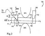
図1および図2は、第1の構成および第2の構成それぞれの、実施形態による、インプラント100の概略図である。インプラント100は、スペーサ140と、近位保持部材160と、遠位保持部材120と、作動装置111とを含む。インプラント100のスペーサ140は、近位面142と、遠位面143と、外面141とを含み、長手方向軸ALを画定している。インプラント100の少なくとも一部が、第1の棘突起SP1と第2の棘突起SP2との間の空間内に配設されるように構成されており、脊椎が伸びる間に、直接または周囲組織を介してのいずれかで、インプラント100のスペーサ140が第1の棘突起SP1と第2の棘突起SP2とに係合するようになっている。換言すれば、少なくとも脊椎が伸びる間に、スペーサ140の外面141は、インプラント100に関連するいずれの介在構造も伴わずに、棘突起SP1、SP2および/または棘突起SP1、SP2を取り巻く身体組織に直接係合するかつ/または接触するように構成されている。いくつかの実施形態では、例えば、スペーサ140の一部が、棘間靱帯(図示せず)に画定されている開口部内に配設される。このようにして、スペーサ140は、棘間靱帯を介して棘突起SP1、SP2に接触することができる。しかし、明確にする目的で、棘突起SP1、SP2を取り巻く組織は図示されていない。1 and 2 are schematic views of an
インプラント100の近位保持部材160は、スペーサ140に連結されており、近位保持部材160の少なくとも一部分がスペーサ140の近位面142に隣接するようになっている。いくつかの実施形態では、近位保持部材160の一部が、スペーサ140の近位面142に接触していることが可能である。他の実施形態では、近位保持部材160は、スペーサ140の近位面142から離間されていることが可能である。いくつかの実施形態では、近位保持部材160は、スペーサ140に可動式に連結され得る。他の実施形態では、近位保持部材160は、スペーサ140に着脱式に連結され得る。
インプラント100の遠位保持部材120は、スペーサ140に可動式に連結されており、第1の面122と、第2の面123と、外面121とを含む。遠位保持部材120の第1の面122により画定されている平面内の軸APは、長手方向軸ALに平行でなく、かつ垂直でない。換言すれば、遠位保持部材120の第1の面122は、長手方向軸ALから角度θ1で角度オフセットされている。本明細書にさらに記載されている通り、遠位保持部材120の第1の面122と長手方向軸ALとにより画定されている角度θ1は、作動装置111の作動面116と長手方向軸ALとにより画定されている角度θ2と補角をなす。さらに、遠位保持部材120の第1の面122は、作動装置111の作動面116に略平行である。The
遠位保持部材120は、スペーサ140に連結されており、遠位保持部材120の第2の面123がスペーサ140の遠位面143に接触しているようになっている。図1および図2に示されている通り、遠位保持部材120の第2の面123は、長手方向軸ALに略垂直である。さらに、遠位保持部材120の第2の面123は、スペーサ140の遠位面143に略平行である。換言すれば、遠位保持部材120の第2の面123は、長手方向軸ALに対してスペーサ140の遠位面143により画定されている角度と補角をなす、長手方向軸ALに対する角度を画定している。The
インプラント100の作動装置111は、スペーサ140に可動式に連結されており、作動面116を含む。作動面116は、遠位保持部材120の第1の面122に滑動可能に連結されおり、それに略平行である。換言すれば、軸A’Pは、作動装置111の作動面116により画定されている平面内にある。図1に示されている通り、作動装置111の作動面116は、長手方向軸ALから角度θ2で角度オフセットされている。前述の通り、作動装置111の作動面116と長手方向軸ALとにより画定されている角度θ2は、角度θ1と補角をなす。
図1および図2に示されている通り、インプラント100は、第1の構成(図1)と第2の構成(図2)との間で移行可能である。インプラント100が第1の構成にある場合、作動装置111は、長手方向軸ALに沿って、ゼロでない距離D1だけ、スペーサ140の遠位面143から離間されている。インプラント100が第1の構成にある場合、遠位保持部材120の外面121は、スペーサ140の外面141と略揃っている。換言すれば、遠位保持部材140の外面121とスペーサ140の外面141とは、実質的に連続的な面を形成している。さらに換言すれば、遠位保持部材120の外面121は、スペーサ140の外面141と実質的に同一平面上にある。さらに換言すれば、遠位保持部材120の第2の面123とスペーサ140の遠位面143とは、整合している。As shown in FIGS. 1 and 2, the
インプラント100を第2の構成へ移行させるために、作動装置111を、長手方向軸ALに沿って、図2に矢印AAAで示されている方向に移動させる。作動装置111の移動により、作動装置111の作動面116は、遠位保持部材120の第1の面122に軸力を掛ける。作動装置111の作動面116は長手方向軸ALに対して角度θ2なので、作動面116を介して遠位保持部材120の第1の面122に伝達される軸力の成分は、図2に矢印BBBで示されている方向を有する。換言すれば、作動装置111により遠位保持部材120に掛けられる力の成分は、長手方向軸ALに略垂直な方向を有する。したがって、作動装置111によって遠位保持部材120に掛けられる力により、遠位保持部材120の第1の面122は、作動装置111の作動面116上を滑動し、遠位保持部材120は、図2に矢印BBBで示されている方向に移動する。To transition the
図2に示されている通り、インプラント100が第2の構成にある場合、作動装置111は、長手方向軸ALに沿って、距離D1より小さいゼロでない距離D2だけ、スペーサ140の遠位面143から離間されている。図2に距離D2だけ離間されて示されているが、他の実施形態では、インプラント100が第2の構成にある場合、作動装置111は、スペーサ140の遠位面143に接触していることが可能である。そのような実施形態では、作動装置111が長手方向軸ALに沿って所定の距離を移動した後に、作動装置111は、スペーサ140の遠位面143に接触して、スペーサ140に対する作動装置111の動きの範囲を制限することができる。As shown in FIG. 2, if the
インプラント100が第2の構成にある場合、遠位保持部材120は、図2に矢印BBBで示されているように、長手方向軸ALに略垂直な方向にスペーサ140からオフセットされている。換言すれば、遠位保持部材120の外面121は、スペーサ140の外面141に揃っておらず、スペーサ140の外面141と不連続である。さらに換言すれば、遠位保持部材120の外面121は、スペーサ140の外面141からゼロでない距離D3だけ離間されている。本明細書にさらに記載されている通り、このようにして、遠位保持部材120と、近位保持部材160と、スペーサ140は、鞍状部を形成する。If the
遠位保持部材120の第1の面122の角度θ1と、作動装置120の作動面116の角度θ2とは、任意の適切な角度とすることができる。インプラント100を第1の構成から第2の構成へ移行させる場合、角度θ1およびθ2の値は、インプラント100を第1の構成から第2の構成へ移行させる力および/または作動装置111が通って移動する軸方向距離に影響を及ぼし得る。より詳細には、角度θ1が180度に近く(例えば、165度と180度の間である)、角度θ2が0度に近い(例えば、0度と15度の間である)場合、インプラント100を第1の構成から第2の構成へ移行させる力は、角度θ1と角度θ2とがいずれも90度に近い場合に必要な力より小さくなる。換言すれば、遠位保持部材120の第1の面122と作動装置111の作動面116とが長手方向軸ALに平行に近い場合、遠位保持部材120の第1の面122と作動装置111の作動面116とが長手方向軸に垂直に近い場合より、インプラント100を第2の構成へ移行させるのに必要な力は小さくなる。しかし、角度θ1が180度に近く、角度θ2が0度に近い場合、インプラント100を第1の構成から第2の構成へ移行させて遠位保持部材120の所望のオフセット(例えば、D3)を達成するために作動装置111が長手方向軸ALに沿って移動する距離は、角度θ1および角度θ2がいずれも90度に近い場合に作動装置111が移動する距離より大きくなる。The angle θ1 of the
使用中、インプラント100が第1の構成(例えば、図1参照)にある場合、インプラント100は、第1の棘突起SP1と第2の棘突起SP2との間に挿入され得る。例えば、医師が、患者の身体内に経皮的にインプラント100を挿入することができる。いくつかの実施形態では、インプラント100は、カニューレを介して経皮的に挿入され得る。いくつかの実施形態では、その全体が参照により本明細書に組み込まれている、「医療インプラントの挿入および除去のための器具および方法(Tools and Methods for Insertion and Removal of Medical Implants)」という名称の米国特許出願代理人整理番号第KYPH−040/02US305363−2272号に記載されているものなどの器具を使用して、インプラント100を患者の身体内に挿入することができる。 In use, when the
インプラント100が第1の棘突起SP1と第2の棘突起SP2との間に入った後、インプラント100を第1の構成から第2の構成(例えば、図2参照)へ移行させることができる。いくつかの実施形態では、インプラントが身体内にある時に、作動装置111をスペーサ140に対して移動させるように構成されている器具(図示せず)を使用して、インプラント100を作動させることができる。そのような器具は、例えば、その全体が参照により本明細書に組み込まれている、「医療インプラントの挿入および除去のための器具および方法(Tools and Methods for Insertion and Removal of Medical Implants)」という名称の米国特許出願代理人整理番号第KYPH−040/02US305363−2272号に記載されている器具を含み得る。前述の通り、インプラント100が第2の構成にある場合、遠位保持部材120と、近位保持部材160と、スペーサ140とは、鞍状部を形成し、その内部に、第1の棘突起SP1が配設される。このようにして、インプラント100が第2の構成にある場合、遠位保持部材120と近位保持部材160とは、集合的に、長手方向軸ALに沿った、第1の棘突起SP1に対するスペーサ140の移動を制限することができる。After the
医師が、インプラント100を身体から除去しかつ/またはインプラント100を身体内に再配置することができる。インプラント100を身体から除去しかつ/または身体内に再配置するために、インプラント100を第2の構成から第1の構成へ移行させることができる。このことは、図2に矢印AAAで示されている方向の反対の方向に作動装置111を移動させることにより実行され得る。これにより、インプラント100は、第1の構成へ戻る。インプラント100が第1の構成になった後、医師は、インプラント100を身体から除去しかつ/またはインプラント100を身体内に再配置することができる。 A physician can remove the
スペーサ140の遠位面143は長手方向軸ALに略垂直であるように示され記載されているが、いくつかの実施形態では、スペーサ140の遠位面143は、長手方向軸ALから角度オフセットされ得る。換言すれば、いくつかの実施形態では、スペーサ140の近位面142および/またはスペーサ140の遠位面143は、90度でない長手方向軸ALに対する角度を画定することができる。例えば、いくつかの実施形態では、スペーサ140の遠位面143は、長手方向軸ALに対して鈍角を画定することができ、遠位保持部材120の第2の面123は、長手方向軸ALに対して、補角をなす鋭角を画定することができる。他の実施形態では、スペーサ140の遠位面143は、長手方向軸ALに対して鋭角を画定することができ、遠位保持部材120の第2の面123は、長手方向軸ALに対して、補角をなす鈍角を画定することができる。インプラント100を第1の構成から第2の構成へ移行させた場合、そのような角度の非垂直配置により、遠位保持部材120は、スペーサ140の遠位面143に略平行な方向に移動する。このように、インプラント100が第1の構成から第2の構成へ移行した場合、スペーサ140の遠位面143の角度は、遠位保持部材120の移動方向に影響を及ぼす。このように、遠位保持部材120は、長手方向軸ALに非垂直な方向に移動するように構成され得る。例えば、いくつかの実施形態では、インプラント100が第1の構成から第2の構成へ移行した場合、遠位保持部材120は、スペーサ111に対して遠位方向に(すなわち棘突起SP1から離れて)移動することができる。他の実施形態では、インプラント100が第1の構成から第2の構成へ移行した場合、遠位保持部材120は、スペーサ111に対して近位方向に(すなわち棘突起SP1の方へ)移動することができる。遠位保持部材120の近位移動を用いて、例えば、第2の構成にある場合に遠位保持部材120を棘突起SP1に接触させることができる。Although the
インプラント100が第1の構成にある場合、遠位保持部材120の外面121は、スペーサ140の外面141に略揃っているように示され記載されているが、いくつかの実施形態では、インプラント100が第1の構成にある場合、遠位保持部材120の外面121は、スペーサの外面141からオフセットされ得る。換言すれば、いくつかの実施形態では、インプラント100が第1の構成にある場合、遠位保持部材120の外面121は、スペーサ140の外面141と不連続にすることができる。さらに換言すれば、いくつかの実施形態では、インプラント100が第1の構成にある場合、遠位保持部材120の外面121は、距離D3(インプラント100が第2の構成にある場合に、遠位保持部材120の外面121がスペーサ140の外面141から離間されている距離)とは異なる距離だけスペーサ140の外面141から離間され得る。 Although the
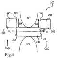
図3および図4は、実施形態による、インプラント200の概略図である。インプラント200は、中央本体240と、近位保持部材260と、遠位保持部材220とを含み、長手方向軸ALを画定している。中央本体240は、近位面242と、遠位面243と、外面241とを含む。インプラント200の中央本体240の少なくとも一部が、第1の棘突起SP1と第2の棘突起SP2との間の空間内に配設されるように構成されており、中央本体240の外面241が、直接または周囲組織を介してのいずれかで、第1の棘突起SP1と第2の棘突起SP2とに係合することができるようになっている。換言すれば、少なくとも脊椎が伸びる間に、中央本体240の外面241は、インプラント200に関連するいずれの介在構造も伴わずに、棘突起SP1、SP2および/または棘突起SP1、SP2を取り巻く身体組織に直接係合するかつ/または接触するように構成されている。いくつかの実施形態では、例えば、中央本体240の一部が、棘間靱帯(図示せず)に画定されている開口部内に配設される。このようにして、中央本体240は、棘間靱帯を介して棘突起SP1、SP2に接触することができる。しかし、明確にする目的で、棘突起SP1、SP2を取り巻く組織は図示されていない。3 and 4 are schematic views of an
インプラント200の近位保持部材260は、外面261と係合面263とを含む。係合面263は、長手方向軸ALに略垂直であり、中央本体240の近位面242に滑動可能に連結されている。したがって、本明細書にさらに詳細に記載されている通り、近位保持部材260は、インプラント200の第1の構成およびインプラント200の第2の構成それぞれに対応する第1の位置と第2の位置との間で、中央本体240に対して移動することができる。近位保持部材260の係合面263は、中央本体240の近位面242に略平行である。換言すれば、係合面263が長手方向軸ALに対して画定している角度は、長手方向軸ALに対して中央本体240の近位面242により画定されている角度と補角をなす。
インプラント200の遠位保持部材220は、外面221と係合面223とを含む。係合面223は、長手方向軸ALに略垂直であり、中央本体240の遠位面243に滑動可能に連結されている。したがって、本明細書にさらに詳細に記載されている通り、遠位保持部材220は、インプラント200の第1の構成およびインプラント200の第2の構成それぞれに対応する第1の位置と第2の位置との間で、中央本体240に対して移動することができる。遠位保持部材220の係合面223は、中央本体240の遠位面243に略平行である。換言すれば、係合面223が長手方向軸ALに対して画定している角度は、長手方向軸ALに対して中央本体240の遠位面243により画定されている角度と補角をなす。The
図3および図4に示されている通り、インプラント200は、第1の構成(図3)と第2の構成(図4)との間で移行可能である。インプラント200が第1の構成にある場合、遠位保持部材220の外面221と、近位保持部材260の外面261と、中央本体240の外面241とは、略揃っている。換言すれば、遠位保持部材220の外面221と、近位保持部材260の外面261と、中央本体240の外面241とは、実質的に連続的な面を形成している。さらに換言すれば、遠位保持部材220の外面221と近位保持部材260の外面261とは、中央本体240の外面241と同一平面上にある。 As shown in FIGS. 3 and 4, the
インプラント200を第2の構成へ移行させるために、近位保持部材260と遠位保持部材220とは、それらを図4に矢印CCCで示されている方向に移動させることにより、それらの第1の位置からそれらの第2の位置へ移動させられる。より詳細には、近位保持部材260と遠位保持部材220とは、中央本体240に対して移動する。換言すれば、近位保持部材260と遠位保持部材220とは、長手方向軸ALに略垂直な方向に移動する。さらに換言すれば、近位保持部材260と遠位保持部材220とはそれぞれ、中央本体240の近位面242と中央本体240の遠位面243とに沿って滑動する。いくつかの実施形態では、近位保持部材260と遠位保持部材220とを、例えば、近位保持部材260および/または遠位保持部材220に係合するように構成されている器具により、移動させることができる。いくつかの実施形態では、インプラント200は、インプラント100の作動装置111と同様の作動装置を含み、近位保持部材260と遠位保持部材220とを、それらの各第1の位置と第2の位置との間で移動させることができる。In order to transition the
インプラント200が第2の構成にある場合、遠位保持部材220と近位保持部材260とは、長手方向軸ALに垂直な方向に、中央本体240からオフセットされている。換言すれば、遠位保持部材220の外面221の少なくとも一部と近位保持部材260の外面261の少なくとも一部とが、中央本体240の外面241から距離D4だけ離間されている。このようにして、本明細書にさらに記載されている通り、遠位保持部材220と、近位保持部材260と、中央本体240とは、鞍状部を形成する。If the
使用中、インプラント200が第1の構成(例えば、図3参照)にある場合、インプラント200は、第1の棘突起SP1と第2の棘突起SP2との間に挿入され得る。例えば、医師が、患者の身体内に経皮的に(例えば、カニューレを介して、ガイドワイヤを介して等)、インプラント200を挿入することができる。いくつかの実施形態では、その全体が参照により本明細書に組み込まれている、「医療インプラントの挿入および除去のための器具および方法(Tools and Methods for insertion and Removal of Medical Implants)」という名称の米国特許出願代理人整理番号第KYPH−040/02US305363−2272号に記載されているものなどの器具を使用して、インプラント200を患者の身体内に挿入することができる。 In use, when the
インプラント200が第1の棘突起SP1と第2の棘突起SP2との間に入った後、インプラント200を第1の構成から第2の構成(例えば、図4参照)へ移行させることができる。いくつかの実施形態では、インプラント200が身体内にある時に、遠位保持部材220と近位保持部材260とを中央本体240に対して移動させるように構成されている器具(図示せず)を使用して、インプラント200を作動させることができる。そのような器具は、遠位保持部材220および/または近位保持部材260に力を掛けながら、中央本体240を固定位置に維持するように構成され得る。そのような器具は、例えば、その全体が参照により本明細書に組み込まれている、「医療インプラントの挿入および除去のための器具および方法(Tools and Methods for Insertion and Removal of Medical Implants)」という名称の米国特許出願代理人整理番号第KYPH−040/02US305363−2272号に記載されている器具を含み得る。前述の通り、インプラント200が第2の構成にある場合、遠位保持部材220と、近位保持部材260と、中央本体240とは、鞍状部を形成し、その内部に、第1の棘突起SP1が配設される。このようにして、インプラント200が第2の構成にある場合、遠位保持部材220と近位保持部材260とは、集合的に、第1の棘突起SP1に対する中央本体240の移動を制限することができる。 After the
医師が、何度も、インプラント200を身体から除去しかつ/または身体内に再配置することができる。インプラント200を身体から除去しかつ/または身体内に再配置するために、インプラント200を第2の構成から第1の構成へ移行させることができる。このことは、遠位保持部材220と近位保持部材260とをそれらの第1の位置に移動させ、かつしたがって、インプラント200をその第1の構成へ移行させることにより実行され得る。インプラント200が第1の構成になった後、医師は、インプラント200を身体から除去しかつ/または身体内に再配置することができる。 The physician can remove and / or reposition the
いくつかの実施形態では、遠位保持部材220は、身体内へのインプラント200の挿入を容易にする先細部分を含み得る。より詳細には、先細部分は、身体組織を伸延させ、拡張し、かつ/または穿孔することができる。いくつかの実施形態では、例えば、インプラント200が身体内に挿入される時に、先細部分は、棘間靱帯などの身体組織を穿孔することができる。いくつかの実施形態では、インプラント200が身体内に挿入される時に、先細部分は、棘間靱帯などの身体組織を拡張することができる。いくつかの実施形態では、インプラント200が身体内に挿入される時に、先細部分は、隣接する棘突起間の空間を伸延させることができる。 In some embodiments, the
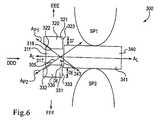
図5および図6は、第1の構成および第2の構成それぞれの、実施形態による、インプラント300の概略図である。インプラント300は、スペーサ340と、第1の保持部材320と、第2の保持部材330と、作動装置311とを含む。スペーサ340は、側面343と外面341とを含み、長手方向軸ALを画定している。インプラント300のスペーサ340の少なくとも一部が、第1の棘突起SP1と第2の棘突起SP2との間の空間内に配設されるように構成されており、スペーサ340の外面341が、直接または周囲組織を介してのいずれかで、第1の棘突起SP1および第2の棘突起SP2に係合することができるようになっている。換言すれば、少なくとも脊椎が伸びる間に、スペーサ340の外面341は、インプラント300に関連するいずれの介在構造も伴わずに、棘突起SP1、SP2および/または棘突起SP1、SP2を取り巻く身体組織に直接係合するかつ/または接触するように構成されている。いくつかの実施形態では、例えば、スペーサ340の一部が、棘間靱帯(図示せず)に画定されている開口部内に配設される。このようにして、スペーサ340は、棘間靱帯を介して棘突起SP1、SP2に接触することができる。しかし、明確にする目的で、棘突起SP1、SP2を取り巻く組織は図示されていない。5 and 6 are schematic views of an
インプラント300の第1の保持部材320は、第1の面322と、第2の面323と、外面321とを含む。第1の保持部材320の第2の面323は、スペーサ340の側面343に滑動可能に連結されている。このように、第1の保持部材320は、スペーサ340に対して移動することができる。第1の保持部材320の第2の面323は、長手方向軸ALに略垂直であり、スペーサ340の側面343に略平行である。換言すれば、第1の保持部材320の第2の面323は、スペーサ340の側面343と長手方向軸ALとにより画定されている角度と補角をなす、長手方向軸ALに対する角度を有する。The
第1の保持部材320の第1の面322は、作動装置311の第1の作動面316に略平行である。第1の保持部材320の第1の面322内の平面により画定されている軸AP1は、長手方向軸ALに平行でなく、かつ垂直でない。換言すれば、第1の保持部材320の第1の面322は、長手方向軸ALから角度θ3で角度オフセットされている。第1の保持部材320の第1の面322と長手方向軸ALとにより画定される角度θ3は、作動装置311の第1の作動面316と長手方向軸ALとにより画定される角度θ4と補角をなす。The
インプラント300の第2の保持部材330は、第1の面332と、第2の面333と、外面331とを含む。第2の保持部材330の第2の面333は、スペーサ340の側面343に滑動可能に連結されている。このように、第2の保持部材330は、スペーサ340に対して移動することができる。第2の保持部材330の第2の面333は、長手方向軸ALに略垂直であり、スペーサ340の側面343に略平行である。換言すれば、第2の保持部材330の第2の面333は、スペーサ340の側面343と長手方向軸ALとにより画定されている角度と補角をなす、長手方向軸ALに対する角度を有する。The
第2の保持部材330の第1の面332は、作動装置311の第2の作動面317に略平行である。第2の保持部材330の第1の面332により画定されている平面内の軸AP2は、長手方向軸ALに対して平行でなく、かつ垂直でない。換言すれば、第2の保持部材330の第1の面332は、長手方向軸ALから角度θ5で角度オフセットされている。第2の保持部材330の第1の面332と長手方向軸ALとにより画定される角度θ5は、作動装置311の第2の作動面317と長手方向軸ALとにより画定される角度θ6と補角をなす。The
インプラント300の作動装置311は、第1の作動面316と第2の作動面317とを有する先細部分305を含む。前述の通り、第1の作動面316は、第1の保持部材320の第1の面322に略平行である。同様に、第2の作動面317は、第2の保持部材330の第1の面332に略平行である。前述の通り、作動装置311の第1の作動面316と長手方向軸ALとにより画定される角度θ4は、第1の保持部材320の第1の面322と長手方向軸ALとにより画定される角度θ3と補角をなす。同様に、作動装置311の第2の作動面317と長手方向軸ALとにより画定される角度θ6は、第2の保持部材330の第1の面332と長手方向軸ALとにより画定される角度θ5と補角をなす。
図5および図6に示されている通り、インプラント300は、第1の構成(図5)と第2の構成(図6)との間で移行可能である。インプラント300が第1の構成にある場合、作動装置311は、長手方向軸ALに沿って、距離D5だけ、スペーサ340の側面343から離間されている。インプラント300が第1の構成にある場合、第1の保持部材320の外面321と、第2の保持部材330の外面331とは、スペーサ340の外面341と略揃っている。換言すれば、第1の保持部材320の外面321と、スペーサ340の外面341とは、実質的に連続的な面を形成している。同様に、第2の保持部材330の外面331とスペーサ340の外面341とは、実質的に連続的な面を形成している。さらに換言すれば、第1の保持部材320の外面321は、スペーサ340の外面341と実質的に同一平面上にある。同様に、第2の保持部材330の外面331は、スペーサ340の外面341と実質的に同一平面上にある。さらに換言すれば、第1の保持部材320の第2の面323と、第2の保持部材330の第2の面333とは、スペーサ340の側面343と略揃っている。As shown in FIGS. 5 and 6, the
インプラント300を第2の構成へ移行させるために、作動装置311を、長手方向軸ALに沿って、図6に矢印DDDで示されている方向に移動させる。作動装置311の移動により、作動装置311の第1の作動面316は、第1の保持部材320の第1の面322に軸力を掛ける。前述の通り、作動装置311の第1の作動面316は長手方向軸ALに対して角度θ4なので、第1の作動面316を介して第1の保持部材320の第1の面322に伝達される軸力の成分は、図6に矢印EEEで示されている方向を有する。したがって、作動装置311により第1の保持部材320の第1の面322に掛けられる力により、第1の保持部材320の第1の面322は、作動装置311の第1の作動面316上を滑動し、第1の保持部材320は、図6に矢印EEEで示されている方向に移動する。To transition the
同様に、図6に矢印DDDで示されている方向の作動装置311の移動により、作動装置の第2の作動面317は、第2の保持部材330の第1の面332に軸力を掛ける。作動装置311の第2の作動面317は長手方向軸ALに対して鋭角θ6なので、第2の作動面317を介して第2の保持部材330の第1の面332に伝達される軸力の成分は、図6に矢印FFFで示されている方向を有する。したがって、作動装置311により第2の保持部材330に掛けられる力により、第2の保持部材330の第1の面332は、作動装置311の第2の作動面317上を滑動し、第2の保持部材330は、図6に矢印FFFで示されている方向に移動する。前述のインプラント100と同様に、角度θ3、θ4、θ5、θ6の値は、インプラント300を第1の構成から第2の構成へ移行させる力およびインプラント300を第1の構成から第2の構成へ移行させるために作動装置311が移動する距離に影響を及ぼす。Similarly, the movement of the
図6に示されている通り、インプラント300が第2の構成にある場合、作動装置311は、長手方向軸ALに沿って、D5より小さい距離D6だけ、スペーサ340の側面343から離間されている。図6に距離D6だけ離間されているように示されているが、他の実施形態では、インプラント300が第2の構成にある場合、作動装置311は、スペーサ340の側面343に接触していることが可能である。そのような実施形態では、作動装置311が長手方向軸ALに沿って所定の距離を移動した後、作動装置311は、スペーサ340に接触し、スペーサ340に対する作動装置311の移動範囲を制限することができる。As shown in FIG. 6, if the
インプラント300が第2の構成にある場合、図6に矢印EEEで示されている通り、第1の保持部材320は、長手方向軸ALに略垂直な方向に、スペーサ340からオフセットされている。換言すれば、第1の保持部材320の外面321は、スペーサ340の外面341から距離D7だけ離間されている。同様に、図6の矢印FFFで示されている通り、第2の保持部材330は、長手方向軸ALに垂直な方向に、スペーサ340からオフセットされている。換言すれば、第2の保持部材330の外面331は、スペーサ340の外面341から距離D8だけ離間されている。さらに換言すれば、第1の保持部材320の外面321と、第2の保持部材330の外面331とは、スペーサ340の外面341と揃っておらず、スペーサ340の外面341と不連続である。If the
使用中、インプラント300が第1の構成(例えば、図5参照)にある場合、インプラント300は、第1の棘突起SP1と第2の棘突起SP2との間に挿入され得る。例えば、医師が、患者の身体内に経皮的に(例えば、カニューレを介して、ガイドワイヤを介して等)、インプラント300を挿入することができる。いくつかの実施形態では、その全体が参照により本明細書に組み込まれている、「医療インプラントの挿入および除去のための器具および方法(Tools and Methods for insertion and Removal of Medical Implants)」という名称の米国特許出願代理人整理番号第KYPH−040/02US305363−2272号に記載されているものなどの器具を使用して、インプラント300を患者の身体内に挿入することができる。 In use, when the
インプラント300が第1の棘突起SP1と第2の棘突起SP2との間に入った後、インプラント300を第1の構成から第2の構成(例えば、図6参照)へ移行させることができる。いくつかの実施形態では、インプラント300が身体内にある時に、作動装置311をスペーサ340に対して移動させるように構成されている器具(図示せず)を使用して、インプラント300を作動させることができる。そのような器具は、作動装置311に力を掛けながら、スペーサ340を固定位置に維持するように構成され得る。そのような器具は、例えば、その全体が参照により本明細書に組み込まれている、「医療インプラントの挿入および除去のための器具および方法(Tools and Methods for Insertion and Removal of Medical Implants)」という名称の米国特許出願代理人整理番号第KYPH−040/02US305363−2272号に記載されている器具を含み得る。インプラント300が第2の構成にある場合、第1の保持部材320と第2の保持部材330とは、第1の棘突起SP1と第2の棘突起SP2とに対する、図6に矢印DDDで示されている方向のインプラント300の移動を制限する。 After the
医師が、何度も、インプラント300を身体から除去しかつ/または身体内に再配置することができる。インプラント300を身体から除去しかつ/または身体内に再配置するために、インプラント300を第2の構成から第1の構成へ移行させる。このことは、第1の保持部材320と第2の保持部材360とをそれらの第1の位置に移動させ、かつしたがって、インプラント300をその第1の構成へ移行させることにより実行され得る。インプラント300が第1の構成になった後、医師は、インプラント300を身体から除去しかつ/または身体内に再配置することができる。 The physician can remove and / or reposition the
いくつかの実施形態では、作動装置は、身体内へのインプラント300の挿入を容易にする第2の先細部分を有し得る。より詳細には、第2の先細部分は、身体組織を伸延させ、拡張し、かつ/または穿孔することができる。いくつかの実施形態では、例えば、インプラント300が身体内に挿入される時に、第2の先細部分は、棘間靱帯などの身体組織を穿孔することができる。いくつかの実施形態では、インプラント300が身体内に挿入される時に、第2の先細部分は、棘間靱帯などの身体組織を拡張することができる。いくつかの実施形態では、インプラント300が身体内に挿入される時に、第2の先細部分は、隣接する棘突起間の空間を伸延させることができる。 In some embodiments, the actuator can have a second tapered portion that facilitates insertion of the
いくつかの実施形態では、角度θ3は角度θ5に等しくない。そのような実施形態では、インプラント300が第2の構成にある場合、第1の保持部材320の外面321と、第2の保持部材330の外面331とは、外面341から不等距離だけ離間されている。したがって、角度θ3が角度θ5より大きい場合、第2の保持部材330の外面331は、スペーサ340の外面341から、第1の保持部材320の外面321より遠くに離間されている。換言すれば、距離D8は距離D7より大きい。In some embodiments, angle θ3 is not equal to angle θ5 . In such an embodiment, when the
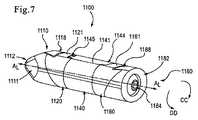
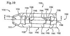
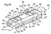
図7〜図13は、実施形態による、インプラント1100を示す。インプラント1100は、遠位端部1110と、中央部分1140と、近位端部1180とを含む。中央部分1140の少なくとも一部が、遠位端部1110と近位端部1180との間に配設されている。インプラント1100は、内腔1146を画定しており、内腔1146内に配設されている駆動ねじ1183を含む。その全体が参照により本明細書に組み込まれている、「医療インプラントの挿入および除去のための器具および方法(Tools and Methods for insertion and Removal of Medical Implants)」という名称の米国特許出願代理人整理番号第KYPH−040/02US305363−2272号に記載されている通り、駆動ねじ1183は、駆動ねじ1183を回転させるための挿入器具の作動装置と嵌合しかつ/またはそれを受容するように構成されている器具頭部1184を有する。 7-13 illustrate an
インプラント1100の遠位端部1110は、作動装置1111と、遠位保持部材1120とを含む。作動装置1111は、先細面1112と、ねじ部分1114(図12参照)と、係合面1116と、突起部1118とを含む。ねじ部分1114は、内腔1146内に固定配設されており、駆動ねじ1183を受容するように構成されている。他の実施形態では、作動装置1111は、駆動ねじ1183を受容するように構成されている拘束ナットを含み得る。 The
作動装置1111の係合面1116は、インプラント1100の長手方向軸ALから0度と90度の間の角度で角度オフセットされている。換言すれば、作動装置1111の係合面1116は、インプラント1100の長手方向軸ALから鋭角で角度オフセットされている。前述の通り、係合面1116の角度オフセットは、インプラント1100を第1の構成(図7)と第2の構成(図8)との間で移行させることに関連している。
係合面1116の突起部1118は、アンダカットを有し、遠位保持部材1120が作動装置1111に滑動可能に連結されるようになっている。より詳細には、突起部1118は、台形の横断面形状を有する。本実施形態では、突起部1118は蟻継ぎほぞ部である。 The
遠位保持部材1120は、外面1121と、第1の係合面1122と、第1の係合面1122の反対側の第2の係合面1123とを含む。遠位保持部材1120は、インプラント1100が第1の構成にある場合に駆動ねじ1183が遠位保持部材1120を通過するのを可能にするように構成されている切欠き1128(図11参照)を画定している。換言すれば、インプラント1100が第1の構成にある場合、切欠き1128は、内腔1146と整合している。 The
遠位保持部材1120の第1の係合面1122は、インプラント1100の長手方向軸ALから90度と180度の間の角度で角度オフセットされている平面を画定している。換言すれば、遠位保持部材1120の第1の係合面1122は、長手方向軸ALから鈍角で角度オフセットされている平面を画定している。さらに、遠位保持部材1120の第1の係合面1122は、作動装置1111の係合面1116に略平行である。換言すれば、遠位保持部材1120の第1の係合面1122の角度オフセットは、作動装置1111の係合面1116の角度オフセットと補角をなす。したがって、遠位保持部材1120は、作動装置1111に当接して滑動可能に配設されている。The
遠位保持部材1120の第1の係合面1122は、台形の横断面形状を有する第1の溝部1124を画定している。本実施形態では、第1の溝部1124は、作動装置1111の突起部1118の形状に対応する蟻継ぎ形状(dovetail shape)を有する。第1の溝部1124は、作動装置1111の突起部1118を滑動式に受容するように構成されている。作動装置1111の突起部1118のアンダカットは、作動装置1111の突起部1118を第1の溝部1124内に滑動可能に維持する。第1の係合面1122の第1の溝部1124と、作動装置1111の突起部1118とは、集合的に、遠位保持部材1120の第1の係合面1122に略平行な方向の、作動装置1111に対する遠位保持部材1120の移動を可能にする。さらに、第1の係合面1122の第1の溝部1124と、作動装置1111の突起部1118とは、集合的に、遠位保持部材1120の第1の係合面1122に略垂直な方向の、作動装置1111に対する遠位保持部材1120の移動を制限する。第1の溝部1124が作動装置1111の突起部1118の周囲を滑動する場合、遠位保持部材1120の第1の係合面1122は、作動装置1111の係合面1116に接触し、それに沿って滑動するように構成されている。このようにして、第1の溝部1124と突起部1118とは、集合的に、作動装置1111を遠位保持部材1120との滑り接触状態に維持する。 The
遠位保持部材1120の第2の係合面1123は、中央部分1140の遠位係合面1143に略平行であり、インプラント1100の長手方向軸ALに略垂直な平面を画定している。遠位保持部材1120の第2の係合面1123は、第2の溝部1126を画定している。第2の溝部1126は、中央部分1140の遠位突起部1145の形状に対応する形状を有する。本明細書にさらに詳細に記載されている通り、遠位保持部材1120の第2の係合面1123は、インプラント1100の中央部分1140に当接して滑動可能に配設されているかつ/またはそれに連結されている。
インプラント1100の近位端部1180は、器具係合部材1182と近位保持部材1160とを含む。以下にさらに詳細に記載されている通り、器具係合部材1182は、挿入器具と嵌合しかつ/またはそれを受容するように構成されている。器具係合部材1182は、係合面1186と突起部1188とを含む。器具係合部材1182の係合面1186は、インプラント1100の長手方向軸ALから0度と90度の間の角度で角度オフセットされている。換言すれば、器具係合部材1182の係合面1186は、インプラント1100の長手方向軸ALから鋭角で角度オフセットされている。前述の通り、係合面1186の角度オフセットは、インプラント1100を第1の構成(図7)と第2の構成(図8)との間で移行させることに関連している。
係合面1186の突起部1188は、アンダカットを有し、近位保持部材1160が器具係合部材1182に滑動可能に連結され得るようになっている。より詳細には、突起部1188は、台形の横断面形状を有する。いくつかの実施形態では、突起部1188は蟻継ぎほぞ部である。 The
近位保持部材1160は、外面1161と、第1の係合面1162と、第1の係合面1162の反対側の第2の係合面1163とを含む。近位保持部材1160は、インプラント1100が第1の構成にある場合に駆動ねじ1183が近位保持部材1160を通過するのを可能にするように構成されている切欠き1168(図11参照)を画定している。換言すれば、インプラント1100が第1の構成にある場合、切欠き1168は、内腔1146と整合している。 Proximal retaining
近位保持部材1160の第1の係合面1162は、インプラント1160の長手方向軸ALから90度と180度の間の角度で角度オフセットされている平面を画定している。近位保持部材1160の第1の係合面1162は、器具係合部材1182の係合面1186に略平行である。換言すれば、近位保持部材1160の第1の係合面1162の角度オフセットは、器具係合部材1182の係合面1186の角度オフセットと補角をなす。したがって、近位保持部材1160は、器具係合部材1182に当接して滑動可能に配設されている。The
さらに、近位保持部材1160の第1の係合面1162は、台形の横断面形状を有する第1の溝部1164を画定している。本実施形態では、第1の溝部1164は、器具係合部材1182の突起部1188の形状に対応する蟻継ぎ形状を有する。第1の溝部1164は、器具係合部材1182の突起部1188を滑動可能に受容するように構成されている。器具係合部材1182の突起部1188のアンダカットは、器具係合部材1182の突起部1188を第1の溝部1164内に維持する。第1の係合面1162の第1の溝部1164と、器具係合部材1182の突起部1188とは、集合的に、近位保持部材1160の第2の係合面1163に略平行な方向の、器具係合部材1182に対する近位保持部材1160の移動を可能にする。さらに、第1の係合面1162の第1の溝部1164と、器具係合部材1182の突起部1188とは、集合的に、近位保持部材1160の第2の係合面1163に略垂直な方向の、器具係合部材1182に対する近位保持部材1160の移動を制限する。近位保持部材1160の第1の溝部1164が器具係合部材1182の突起部1188に沿って滑動する場合、近位保持部材1160の第1の係合面1162は、器具係合部材1182の係合面1186に接触し、それに沿って滑動するように構成されている。このようにして、第1の溝部1164と突起部1188とは、集合的に、器具係合部材1182を近位保持部材1160との滑り接触状態に維持する。 Further, the
近位保持部材1160の第2の係合面1163は、中央部分1140の近位係合面1142に略平行であり、インプラント1100の長手方向軸ALに略垂直な平面を画定している。しかし、他の実施形態では、近位保持部材1160の第2の係合面1163により画定されている平面は、インプラント1100の長手方向軸ALから90度以外の角度で角度オフセットされ得る。さらに、近位保持部材1160の第2の係合面1163は、第2の溝部1166を画定している。第2の溝部1166は、中央部分1140の近位突起部1144の形状に対応する形状を有する。本明細書にさらに詳細に記載されている通り、近位保持部材1160の第2の係合面1163は、インプラント1100の中央部分1140に当接して滑動可能に配設されておりかつ/またはそれに連結されている。
インプラント1100の中央部分1140は、近位係合面1142と、遠位係合面1143と、近位突起部1144と、遠位突起部1145と、外面1141とを含む。遠位保持部材1120は、中央部分1140に滑動可能に連結されている。より詳細には、遠位保持部材1120の第2の溝部1126は、中央部分1140の遠位突起部1145を滑動式に受容するように構成されている。遠位保持部材1120の第2の溝部1126が中央部分1140の遠位突起部1145に沿って滑動する場合、遠位保持部材1120の第2の係合面1123は、中央部分1140の遠位係合面1143に接触し、それに沿って滑動するように構成されている。 The
同様に、近位保持部材1160は、中央部分1140に滑動可能に連結されている。近位保持部材1160の第2の溝部1166は、中央部分1140の近位突起部1144を滑動式に受容するように構成されている。中央部分1140の近位突起部1144は、近位保持部材1160の第2の溝部1166内に滑動可能に維持される。近位保持部材1160の第2の溝部1166が中央部分1140の近位突起部1144に沿って滑動する場合、近位保持部材1160の第2の係合面1163は、中央部分1140の近位係合面1142に接触し、それに沿って滑動するように構成されている。 Similarly, the
インプラント1100は、第1の構成(図7)と第2の構成(図8)とを有する。図7に示されている通り、インプラント1100が第1の構成にある場合、近位端部1180と、遠位端部1110と、中央部分1140とは、実質的に同軸である(すなわち共通の長手方向軸を実質的に共有している)。換言すれば、インプラント1100が第1の構成にある場合、遠位保持部材1120の外面1121と、近位保持部材1160の外面1161とは、中央部分1140の外面1141と略揃っている。換言すれば、遠位保持部材1120の外面1121と、近位保持部材1160の外面1161と、中央部分1140の外面1141とは、実質的に連続的な面を形成している。さらに換言すれば、遠位保持部材1120の外面1121と、近位保持部材1160の外面1161とは、中央部分1140の外面1141と同一平面上にある。 The
インプラント1100を、第1の構成と図8に示されている第2の構成との間で移行させることができる。インプラント1100を第1の構成から第2の構成へ移行させるために、駆動ねじ1183を、図7に矢印CCで示されているように回転させる。駆動ねじ1183が回転すると、駆動ねじ1183は、作動装置1111と器具係合部材1182とを中央部分1140の方へ移動させる。より詳細には、駆動ねじ1183が回転すると、作動装置1111の係合面1116は、遠位保持部材1120の第1の係合面1122に軸力を掛ける。作動装置1111の係合面1116は長手方向軸ALに対して鋭角なので、係合面1116を介して遠位保持部材1120の第1の係合面1122に伝達される軸力の成分は、図8に矢印AAで示されている方向を有する。換言すれば、作動装置1111により遠位保持部材1120に掛けられる力の成分は、長手方向軸ALに略垂直な方向を有する。この力により、遠位保持部材1120は、作動装置1111の係合面1116上を滑動し、遠位保持部材1120は、方向AAに移動し、第2の構成へ移行する。遠位保持部材1120が作動装置1111の係合面1116上で所定の距離を滑動すると、作動装置1111の係合面1116の一部が、中央部分1140の遠位係合面1143の一部に接触し(例えば、図9参照)、遠位保持部材1120がさらに滑動するのを防止する。The
同様に、駆動ねじ1183が図7に矢印CCで示されているように回転した場合、器具係合部材1182の係合面1186は、近位保持部材1160の第1の係合面1162に軸力を掛ける。器具係合部材1182の係合面1186は、長手方向軸ALに対して鋭角なので、係合面1186を介して近位保持部材1160の第1の係合面1162に伝達される軸力の成分は、図8に矢印AAで示されている方向を有する。換言すれば、器具係合部材1182により近位保持部材1160に掛けられる力の成分は、長手方向軸ALに略垂直な方向を有する。この力により、近位保持部材1160は、器具係合部材1182の係合面1186上を滑動し、近位保持部材1160は、方向AAに移動し、第2の構成へ移行する。近位保持部材1160が器具係合部材1182の係合面1186上で所定の距離を滑動すると、器具係合部材1182の係合面1186の一部が、中央部分1140の近位係合面1142に接触し、近位保持部材1160がさらに滑動するのを防止する。Similarly, when the
インプラント1100が第2の構成にある場合、遠位保持部材1120および/または近位保持部材1160は、長手方向軸ALに略垂直な方向に、中央部分1140からオフセットされている。換言すれば、遠位保持部材1120の外面1121および/または近位保持部材1160の外面1161は、中央部分1140の外面1141と揃っておらず、中央部分1140の外面1141と不連続である。If the
使用中、第1の構成のインプラント1100は、一対の隣接する棘突起(図7〜図13に図示せず)間に経皮的に挿入される。例えば、医師が、患者の身体内に経皮的に(例えば、カニューレを介して、ガイドワイヤを介して等)、インプラント1100を挿入することができる。いくつかの実施形態では、その全体が参照により本明細書に組み込まれている、「医療インプラントの挿入および除去のための器具および方法(Tools and Methods for insertion and Removal of Medical Implants)」という名称の米国特許出願代理人整理番号第KYPH−040/02US305363−2272号に記載されているものなどの挿入器具を使用して、インプラント1100を患者の身体内に挿入することができる。挿入器具は、器具係合部材1182に着脱式に連結されるように構成することができ、長手方向軸ALを中心とする、挿入器具に対する器具係合部材1182の回転が制限されるようになっている。いくつかの実施形態では、挿入器具は、器具係合部材1182に着脱式に連結されるように構成されることが可能であり、挿入器具に対する器具係合部材1182の軸方向移動が制限されるようになっている。いくつかの実施形態では、例えば、挿入器具は、器具係合部材1182の外面に連結され得る。いくつかの実施形態では、器具係合部材1182の外面は、インプラント1100への挿入器具(図示せず)の連結を容易にするように構成することができる。例えば、いくつかの実施形態では、器具係合部材1182の外面は、インプラント1100の器具係合部材1182上への挿入器具の連結を容易にする導入溝部、先細部分、および/または傾斜縁部を含み得る。他の実施形態では、挿入器具は、器具係合部材の突起部および/または凹部に嵌合式に連結され得る。挿入器具は、駆動ねじ1183の器具頭部1184内に挿入されて、長手方向軸ALを中心に駆動ねじ1183を回転させるように構成されている作動装置を含み得る。この配置により、駆動ねじ1183が、インプラント1100の他の部分を回転させることなく回転することが可能になる。In use, the
インプラント1100を患者の身体内に挿入する場合、インプラント1100の遠位端部1110は、最初に挿入され、中央部分1140の少なくとも一部が棘突起間の空間内に配置されるまで、棘突起を越えて移動させられる。このようにして、インプラント1100の中央部分1140は、隣接する棘突起間の最小間隔を伸延させかつ/または維持することができる。中央部分1140の外面1141の上部と下部との間の距離は、周囲の靱帯および組織を調節するために棘突起間の空間より若干小さくすることができる。インプラント100の中央部分140と同様に、いくつかの実施形態では、第1の構成の中央部分1140は、それが間に配置されている棘突起に直接接触する。いくつかの実施形態では、インプラント1100の中央部分1140は、比較的固定された大きさであり、実質的に圧縮性または拡張性でない。 When the
棘突起間に入ると、インプラント1100を第1の構成から第2の構成へ移行させることができる。前述の通り、挿入器具を使用して、その位置で、インプラント1100を第1の構成と第2の構成との間で移行させることができる。第2の構成では、近位保持部材1160と遠位保持部材1120とは、中央部分1140からオフセットされており、棘突起に対するインプラント1100の横移動を制限するように配置されている。第2の構成にある場合、近位保持部材1160と遠位保持部材1120とは、上棘突起に係合する(すなわち直接または周囲組織を介してのいずれかで)かつ/または上棘突起に隣接するように構成されている。換言すれば、遠位保持部材1120と、近位保持部材1160と、スペーサ1140とは、その内部に棘突起が配設され得る鞍状部を形成する。インプラント1100が第2の構成にあると、インプラント1100は、挿入器具から解放されることが可能であり、挿入器具は、患者の身体から除去され得る。上棘突起に係合するように記載されているが、他の実施形態では、インプラント1100は、作動時に近位保持部材1160と遠位保持部材1120とが下棘突起に係合する向きに、身体内に配置され得る。 Once between the spinous processes, the
インプラント1100を身体から除去しかつ/または身体内に再配置するために、例えば除去器具(挿入器具と似ている可能性がある)により、図7に矢印DDで示されているように、駆動ねじ1183を回転させる。駆動ねじを方向DDに回転させることにより、作動装置1111の突起部1118の蟻継ぎ構成(dovetail configuration)および/または器具係合部材1182の突起部1188の蟻継ぎ構成は、遠位保持部材1120と近位保持部材1160とを第1の構成へ引き戻す。インプラント1100が第1の構成になった後、医師が、インプラント1100を身体から除去しかつ/またはインプラント1100を身体内に再配置することができる。 Drive to remove
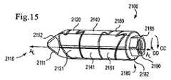
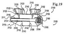
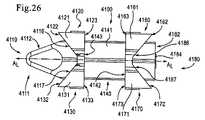
図14〜図21は、実施形態による、インプラント2100を示す。インプラント2100は、遠位端部2110と、中央部分2140と、近位端部2180とを含む。中央部分2140の少なくとも一部が、遠位端部2110と近位端部2180との間に配設されている。インプラント2100は、内腔2146(例えば、図20および図21参照)を画定しており、内腔2146内に配設されている駆動ねじ2183を含む。本明細書にさらに詳細に記載されている通り、駆動ねじ2183は、駆動ねじ2183を回転させるための器具と嵌合するかつ/またはそれを受容するように構成されている器具頭部2184を有する。 14-21 illustrate an
インプラント2100の遠位端部2110は、作動装置2111と遠位保持部材2120とを含む。作動装置2111は、先細面2112と、ねじ部分2114(図16参照)と、係合面2116とを含む。前述の通り、ねじ部分2114は、内腔2146内に固定配設されており、駆動ねじ2183を受容するように構成されている。作動装置2111の係合面2116は、インプラント2100の長手方向軸ALから0度と90度の間の角度で角度オフセットされている。本明細書にさらに詳細に記載されている通り、係合面2116の角度オフセットは、インプラント2100を第1の構成(図14)と第2の構成(図17)との間で移行させることに関連している。係合面2116はアンダカットを有する突起部2118を含み、遠位保持部材2120が作動装置2111に連結され得るようになっている。より詳細には、突起部2118は、台形の横断面形状を有する。いくつかの実施形態では、突起部2118は蟻継ぎほぞ部である。The
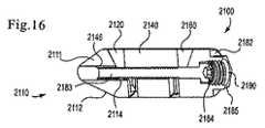
遠位保持部材2120は、外面2121と、第1の係合面2122と、第1の係合面2122の反対側の第2の係合面2123とを含む。遠位保持部材2120は、インプラント2100が第1の構成にある場合に駆動ねじ2183が遠位保持部材2120を通過するのを可能にするように構成されている切欠き2128(図19参照)を画定している。遠位保持部材2120の第1の係合面2122は、インプラント2100の長手方向軸ALから90度と180度の間の角度で角度オフセットされている平面を画定している。さらに、遠位保持部材2120の第1の係合面2122は、作動装置2111の係合面2116に略平行である。したがって、遠位保持部材2120は、作動装置2111に当接して滑動可能に配設されている。The
遠位保持部材2120の第1の係合面2122は、台形の横断面形状を有する第1の溝部2124を画定している。本実施形態では、第1の溝部2124は、作動装置2111の突起部2118の形状に対応する蟻継ぎ形状を有する。第1の係合面2122の第1の溝部2124と、作動装置2111の突起部2118とは、集合的に、遠位保持部材2120の第2の係合面2123に略平行な方向の、作動装置2111に対する遠位保持部材2120の移動を可能にする。さらに、第1の係合面2122の第1の溝部2124と、作動装置2111の突起部2118とは、集合的に、遠位保持部材2120の第2の係合面2123に略垂直な方向の、作動装置2111に対する遠位保持部材2120の移動を制限する。第1の溝部2124が作動装置2111の突起部2118に沿って滑動する場合、遠位保持部材2120の第1の係合面2122は、作動装置2111の係合面2116に接触し、それに沿って滑動するように構成されている。 The
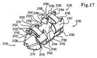
遠位保持部材2120の第2の係合面2123は、中央部分2140の遠位係合面2143に略平行であり、インプラント2100の長手方向軸ALに略垂直な平面を画定している。遠位保持部材2120の第2の係合面2123は、台形の横断面形状を有する第2の溝部2126を画定している。本実施形態では、第2の溝部2126は、中央部分2140の遠位突起部2145の形状に対応する蟻継ぎ形状を有する。第2の係合面2123の第2の溝部2126と、中央本体2140の遠位突起部2145とは、集合的に、遠位保持部材2120の第2の係合面2123に略垂直な方向の、中央部分2140に対する遠位保持部材2120の移動を制限する。本明細書にさらに詳細に記載されている通り、遠位保持部材2120の第2の係合面2123は、インプラント2100の中央部分2140に当接して滑動可能に配設されかつ/またはそれに連結されている。
図18〜図19に示されている通り、遠位保持部材2120の第1の係合面2122は、遠位保持部材2120の第2の係合面2123に平行でない。前述の通り、嵌合している突起部および溝部、ならびに第1の係合面2122と第2の係合面2123との平行でない配置は、集合的に、遠位保持部材2120を作動装置2111と中央本体2140との間に係止する。換言すれば、第1の溝部2124と作動装置2111の突起部2118とは、集合的に、第2の係合面2123に略垂直な方向の、作動装置2111に対する遠位保持部材2120の移動を制限し、第2の溝部2126と中央本体2140の遠位突起部2145とは、集合的に、第2の係合面2123に略垂直な方向の、中央部分2140に対する遠位保持部材2120の移動を制限するので、遠位保持部材2120は、作動装置2111が移動しない限り、移動することができない。この配置により、遠位保持部材2120が作動装置2111および/または中央本体2140から不注意で分離されることが防止される。 As shown in FIGS. 18-19, the
インプラント2100の近位端部2180は、器具係合部材2182と近位保持部材2160とを含む。器具係合部材2182は、挿入器具に嵌合しかつ/またはそれを受容するように構成されている。器具係合部材2182は、係合面2186と六角形部分2185とを含む。六角形部分2185は、挿入器具の一部分内に嵌合式に受容されるように構成されている六角形形状の外面を含む。このようにして、インプラント2100が挿入器具に連結されている場合、器具係合部材2182の六角形部分2185は、長手方向軸ALを中心とするインプラント2100の回転運動を制限することができる。いくつかの実施形態では、六角形部分2185の六角形形状の外面は、インプラント2100の六角形部分2185上への挿入器具(図示せず)の連結を容易にするように構成され得る。例えば、いくつかの実施形態では、六角形部分2185の外面は、インプラント2100の六角形部分2185上への挿入器具の連結を容易にする導入溝部、先細部分、および/または傾斜縁部を含み得る。
六角形部分2185は、挿入器具(図示せず)の対応するねじ部分と嵌合しかつ/またはそれを受容するように構成されているねじ部分2190を画定している。いくつかの実施形態では、例えば、ねじ部分2190は、その全体が参照により本明細書に組み込まれている、「医療インプラントの挿入および除去のための器具および方法(Tools and Methods for insertion and Removal of Medical Implants)」という名称の米国特許出願代理人整理番号第KYPH−040/02US305363−2272号に示され記載されている器具のねじ中間主軸1430の一部を受容することができる。このようにして、以下にさらに詳細に記載されている通り、インプラント2100が患者の身体内に挿入された場合、ねじ部分2190は、挿入器具に対するインプラント2100の軸方向移動を制限することができる。さらに、挿入器具の主軸がねじ部分2190内で結合された場合、器具係合部材2182に対する長手方向軸に沿った駆動ねじ2183の移動は制限される。このように、ねじ部分2190内での挿入器具の結合により、駆動ねじ2183の移動が防止され、それにより、インプラント2100を第1の構成に維持することができる。他の実施形態では、ねじ部分2190は、器具係合部材2182に対する駆動ねじ2183の移動を防止する保持具(例えば、スナップリング、E−リング等)を含み得る。
器具係合部材1182の係合面1186と同様に、器具係合部材2182の係合面2186は、インプラント2100の長手方向軸ALから0度と90度の間の角度で角度オフセットされている。係合面2186はアンダカットを有する突起部2188を含み、近位保持部材2160を器具係合部材2182に連結させることができるようになっている。より詳細には、突起部2188は、台形の横断面形状を有する。本実施形態では、突起部2188は蟻継ぎほぞ部である。Similar to the
近位保持部材2160は、外面2161と、第1の係合面2162と、第1の係合面2162の反対側の第2の係合面2163とを含む。近位保持部材2160は、インプラント2100が第1の構成にある場合に駆動ねじ2183が近位保持部材2160を通過するのを可能にするように構成されている切欠き2168(図21参照)を画定している。近位保持部材2160の第1の係合面2162は、インプラント2160の長手方向軸ALから90度と180度の間の角度で角度オフセットされている平面を画定している。さらに、近位保持部材2160の第1の係合面2162は、器具係合部材2182の係合面2186に略平行である。したがって、近位保持部材2160は、器具係合部材2182に当接して滑動可能に配設されている。Proximal retaining
近位保持部材2160の第1の係合面2162は、台形の横断面形状を有する第1の溝部2164を画定している。本実施形態では、第1の溝部2164は、器具係合部材2182の突起部2188の形状に対応する蟻継ぎ形状を有する。器具係合部材2182の突起部2188のアンダカットは、器具係合部材2182の突起部2188を第1の溝部2164内に滑動可能に維持する。より詳細には、第1の係合面2162の第1の溝部2164と、器具係合部材2182の突起部2188とは、集合的に、近位保持部材2160の第2の係合面2163に略平行な方向の、器具係合部材2182に対する近位保持部材2160の移動を可能にする。さらに、第1の係合面2162の第1の溝部2164と、器具係合部材2182の突起部2188とは、集合的に、近位保持部材2160の第2の係合面2163に略垂直な方向の、器具係合部材2182に対する近位保持部材2160の移動を制限する。近位保持部材2160の第1の溝部2164が器具係合部材2182の突起部2188に沿って滑動する場合、近位保持部材2160の第1の係合面2162は、器具係合部材2182の係合面2186に接触し、それに沿って滑動するように構成されている。 The
近位保持部材2160の第2の係合面2163は、中央部分2140の近位係合面2142に略平行であり、インプラント2100の長手方向軸ALに略垂直な平面を画定している。近位保持部材2160の第2の係合面2163は、台形の横断面形状を有する第2の溝部2166を画定している。本実施形態では、第2の溝部2166は、中央部分2140の近位突起部2144の形状に対応する蟻継ぎ形状を有する。第2の係合面2163の第2の溝部2166と、中央部分2140の近位突起部2144とは、集合的に、近位保持部材2160の第2の係合面2163に略垂直な方向の、中央本体2140に対する近位保持部材2160の移動を制限する。本明細書にさらに詳細に記載されている通り、近位保持部材2160の第2の係合面2163は、インプラント2100の中央部分2140に当接して滑動可能に配設されておりかつ/またはそれに連結されている。
図18〜図19に示されている通り、近位保持部材2160の第1の係合面2162は、近位保持部材2160の第2の係合面2163に平行でない。前述の通り、嵌合している突起部と溝部、ならびに第1の係合面2162および第2の係合面2163の平行でない係合は、集合的に、近位保持部材2160を器具係合部材2182と中央本体2140との間に係止する。換言すれば、第1の溝部2164と器具係合部材2182の突起部2188とは、集合的に、第1の係合面2162に略垂直な方向の、器具係合部材2182に対する近位保持部材2160の移動を制限し、第2の溝部2166と中央本体2140の近位突起部2144とは、集合的に、第2の係合面2163に略垂直な方向の、中央部分2140に対する近位保持部材2160の移動を制限するので、近位保持部材2160は、器具係合部材2182が移動しない限り、移動することができない。この配置により、近位保持部材2160が器具係合部材2182および/または中央本体2140から不注意で分離されることが防止される。 As shown in FIGS. 18-19, the
インプラント2100の中央部分2140は、近位係合面2142と、遠位係合面2143と、近位突起部2144と、遠位突起部2145と、外面2141とを含む。遠位保持部材2120は、中央部分2140に滑動可能に連結されている。遠位保持部材2120の第2の溝部2126は、中央部分2140の遠位突起部2145を滑動式に受容するように構成されている。中央部分2140の遠位突起部2145は、それを遠位保持部材2120の第2の溝部2126内に滑動可能に維持する蟻継ぎ形状を有する。遠位保持部材2120の第2の溝部2126が中央部分2140の遠位突起部2145に沿って滑動する場合、遠位保持部材2120の第2の係合面2123は、中央部分2140の遠位係合面2143に接触し、それに沿って滑動するように構成されている。 The
同様に、近位保持部材2160は、中央部分2140に滑動可能に連結されている。近位保持部材2160の第2の溝部2166は、中央部分2140の近位突起部2144を滑動式に受容するように構成されている。中央部分2140の近位突起部2144は、それを近位保持部材2160の第2の溝部2166内に滑動可能に維持する蟻継ぎ形状を有する。近位保持部材2160の第2の溝部2166が中央部分2140の近位突起部2144に沿って滑動する場合、近位保持部材2160の第2の係合面2163は、中央部分2140の近位係合面2142に接触し、それに沿って滑動するように構成されている。 Similarly, the
インプラント2100は、第1の構成(図14)と第2の構成(図18)とを有する。インプラント2100が第1の構成にある場合、近位端部2180と、遠位端部2110と、中央部分2140とは、実質的に同軸である(すなわち共通の長手方向軸を実質的に共有している)。前述の通り、駆動ねじ2183を回転させることにより、インプラント2100を第1の構成と第2の構成との間で移行させることができる。駆動ねじ2183が図15に矢印CCで示されているように回転した場合、駆動ねじ2183は、作動装置2111と器具係合部材2182とを中央部分2140の方へ移動させる。作動装置2111の係合面2116は、遠位保持部材2120の第1の係合面2122に軸力を掛ける。作動装置2111の係合面2116は長手方向軸ALに対して鋭角なので、係合面2116を介して遠位保持部材2120の第1の係合面2122に伝達される軸力の成分は、図18に矢印AAで示されている方向を有する。換言すれば、作動装置2111により遠位保持部材2120に掛けられる力の成分は、長手方向軸ALに略垂直な方向を有する。この力により、遠位保持部材2120は、作動装置2111の係合面2116上を滑動し、遠位保持部材2120は、方向AAに移動し、第2の構成へ移行する。遠位保持部材2120が作動装置2111の係合面2116上で所定の距離を滑動すると、作動装置2111の係合面2116の一部が、中央部分2140の遠位係合面2143の一部に接触し、遠位保持部材2120がさらに滑動するのを防止する。The
同様に、駆動ねじ2183が図15に矢印CCで示されているように回転した場合、器具係合部材2182の係合面2186は、近位保持部材2160の第1の係合面2162に軸力を掛ける。器具係合部材2182の係合面2186は、長手方向軸ALに対して鋭角なので、係合面2186を介して近位保持部材2160の第1の係合面2162に伝達される軸力の成分は、図18の矢印AAで示されている方向を有する。換言すれば、器具係合部材2182により近位保持部材2160に掛けられる力の成分は、長手方向軸ALに略垂直な方向を有する。この力により、近位保持部材2160は、器具係合部材2182の係合面2186上を滑動し、近位保持部材2160は、方向AAに移動し、第2の構成へ移行する。近位保持部材2160が器具係合部材2180の係合面2186上で所定の距離を滑動すると、器具係合部材2180の係合面2186の一部が、中央部分2140の近位係合面2142に接触し、近位保持部材2160がさらに滑動するのを防止する。インプラント1100と同様に、インプラント2100が第2の構成にある場合、遠位保持部材2120および/または近位保持部材2160は、長手方向軸ALに略垂直な方向に、中央部分2140からオフセットされている。Similarly, when the
使用中、第1の構成のインプラント2100は、一対の隣接する棘突起(図14〜図21に図示せず)間に経皮的に挿入される。例えば、医師が、患者の身体内に経皮的に(例えば、カニューレを介して、ガイドワイヤを介して等)、インプラント2100を挿入することができる。いくつかの実施形態では、その全体が参照により本明細書に組み込まれている、「医療インプラントの挿入および除去のための器具および方法(Tools and Methods for insertion and Removal of Medical Implants)」という名称の米国特許出願代理人整理番号第KYPH−040/02US305363−2272号に記載されているものなどの挿入器具を使用して、インプラント2100を患者の身体内に挿入することができる。挿入器具は、器具係合部材2182に着脱式に連結されるように構成されることが可能であり、長手方向軸ALを中心とする、挿入器具に対する器具係合部材2182の回転が制限されるようになっている。より詳細には、挿入器具の一部が、器具係合部材2182の六角形部分2185の周囲に配設されることが可能であり、長手方向軸ALを中心とする回転運動が制限されるようになっている。さらに、挿入器具は、六角形部分2185のねじ部分2190内でねじ式に結合されるように構成されているねじ部分を含み得る。このようにして、挿入器具は、器具係合部材2182に着脱式に連結されることが可能であり、挿入器具に対する器具係合部材2182の軸方向移動が制限されるようになっている。In use, the
挿入器具は、駆動ねじ2183の器具頭部2184内に挿入されて、長手方向軸ALを中心に駆動ねじ2183を回転させるように構成されている作動装置を含み得る。この配置により、駆動ねじ2183が、インプラント2100の他の部分を回転させることなく回転することが可能になる。したがって、前述の通り、インプラント2100は、身体内に挿入され、再配置され、かつ/またはそこから除去されることが可能である。Insertion device is inserted into the
棘突起間に入ると、インプラント2100を第1の構成から第2の構成へ移行させることができる。第2の構成では、近位保持部材2160と遠位保持部材2120とは、中央部分2140からオフセットされており、棘突起に対するインプラント2100の横移動を制限するように配置されている。近位保持部材2160と遠位保持部材2120とは、棘突起に係合する(すなわち直接または周囲組織を介して)ように構成されており、かつ/または第2の構成にある場合には棘突起に隣接している。換言すれば、遠位保持部材2120と、近位保持部材2160と、中央部分2140とは、鞍状部を形成し、その内部に棘突起が配設され得る。 Once between the spinous processes, the
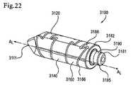
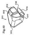
図22〜図23は、実施形態による、インプラント3100を示す。図22に示されている通り、インプラント3100は、作動装置3111と、遠位保持部材3120と、中央部分3140と、近位保持部材3160と、器具係合部材3182とを含む。作動装置3111、遠位保持部材3120、中央部分3140、および近位保持部材3160の構造および動作はそれぞれ、作動装置2111、遠位保持部材2120、中央部分2140、および近位保持部材2160の構造および動作に類似している。したがって、器具係合部材3182のみが以下に詳細に記載される。 22-23 illustrate an
器具係合部材3182は、係合面3186と連結用突起部3185とを含む。係合面3186は蟻継ぎほぞ部3188を含み、これは、インプラント2100の係合面2186および突起部2118それぞれの構造および動作に類似している。したがって、係合面3186および蟻継ぎほぞ部3188は詳細に記載されない。 The
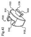
器具連結用突起部3185は、挿入器具3195に着脱式に連結されるように構成されている。挿入器具3195の詳細は、その全体が参照により本明細書に組み込まれている、「医療インプラントの挿入および除去のための器具および方法(Tools and Methods for insertion and Removal of Medical Implants)」という名称の同時係属の米国特許出願代理人整理番号第KYPH−040/02US305363−2272号により詳細に記載されている。具体的には、器具連結用突起部3185は、挿入器具3195の主軸3197を受容するように構成されている。主軸3197の端部が、駆動ねじ3183の器具頭部3184に係合するように構成されている。前述の通り、使用中、主軸3197は、駆動ねじ3183を回転させて、インプラント3100を第1の構成と第2の構成との間で移行させることができる。 The
さらに、器具連結用突起部3185は、挿入器具3195のスナップリング3196を受容するように構成されている溝部3190を含む。スナップリング3196は、例えばばねコイルとすることができる。このようにして、インプラント3100が患者の身体内に挿入された場合、挿入器具3195は、インプラント3100を保持することができる。より詳細には、挿入器具3195に対するインプラント3100の軸方向移動および回転運動がいずれも制限されるように、スナップリング3196と溝部3190とは、集合的に、締まり嵌めを形成することができる。 In addition, the
器具連結用突起部3185は、インプラント3100への挿入器具3195の連結を容易にする導入溝部3181を含む。図23に示されていないが、いくつかの実施形態では、連結用突起部3185により画定されている内腔もまた、連結用突起部3185内への挿入器具3195の主軸3197の挿入を容易にする導入溝部、先細部分、および/または傾斜縁部を含み得る。換言すれば、いくつかの実施形態では、連結用突起部3185は内径溝部を含み得る。
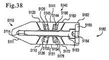
図24〜図30は、実施形態による、インプラント4100を示す。インプラント4100は、遠位端部4110と、中央部分4140と、近位端部4180とを含む。中央部分4140の少なくとも一部分が、遠位端部4110と近位端部4180との間に存在する。インプラント4100は、内腔4146を画定しており、内腔4146内に配設されている駆動ねじ4183を含む。本明細書にさらに詳細に記載されている通り、駆動ねじ4183は、駆動ねじ4183を回転させるための器具に嵌合しかつ/またはそれを受容するように構成されている器具頭部4184を有する。 24-30 illustrate an
インプラント4100の遠位端部4110は、作動装置4111と、第1の遠位保持部材4120と、第2の遠位保持部材4130とを含む。作動装置4111は、先細面4112と、ねじ部分4114(図28参照)と、第1の係合面4116と、第2の係合面4117と、第1の突起部4118と、第2の突起部4119と、第1の安定化ピン4113および第2の安定化ピン4115(図28参照)とを含む。ねじ部分4114は、内腔4146内に固定配設されており、駆動ねじ4183を受容するように構成されている。他の実施形態では、挿入部材は、駆動ねじを受容するように構成されている拘束ナットを含み得る。作動装置4111の第1の安定化ピン4113と第2の安定化ピン4115とは、作動装置4111を中央部分4140に滑動可能に連結して、中央部分4140に対する作動装置4111の単独の回転運動を防止するように構成されている細長い部材である。 The
作動装置4111の第1の係合面4116は、インプラント4100の長手方向軸ALから0度と90度の間の角度で角度オフセットされている。本明細書にさらに詳細に記載されている通り、第1の係合面4116の角度オフセットは、インプラント4100を第1の構成(図24)と第2の構成(図25)との間で移行させることに関連している。The
第1の係合面4116は、アンダカットを有する第1の突起部4118を含む。より詳細には、第1の突起部4118は、台形の横断面形状を有する。本実施形態では、第1の突起部4118は蟻継ぎほぞ部である。第1の突起部4118は、第1の遠位保持部材4120の溝部4124に係合するように構成されている。同様に、第2の係合面4117は、アンダカットを有する第2の突起部4119を含む。より詳細には、第2の突起部4119は、台形の横断面形状を有する。本実施形態では、第2の突起部4119は蟻継ぎほぞ部である。第2の突起部4119は、第2の遠位保持部材4130の溝部4134に係合するように構成されている。 The
第1の遠位保持部材4120は、外面4121と、第1の係合面4122と、第1の係合面4122の反対側の第2の係合面4123とを含む。第1の遠位保持部材4120は、インプラント4100が第1の構成にある場合に駆動ねじ4183が該第1の遠位保持部材を通過するのを可能にするように構成されている切欠き4128を画定している。換言すれば、インプラント4100が第1の構成にある場合、切欠き4128は、内腔4146と整合している。 The first
第1の遠位保持部材4120の第1の係合面4122は、インプラント4100の長手方向軸ALから90度と180度の間の角度で角度オフセットされている平面を画定している。換言すれば、第1の遠位保持部材4120の第1の係合面4122は、長手方向軸ALから鈍角で角度オフセットされている平面を画定している。さらに、第1の遠位保持部材4120の第1の係合面4122は、作動装置4111の第1の係合面4116に略平行である。換言すれば、遠位保持部材4120の第1の係合面4122の角度オフセットは、作動装置4111の第1の係合面4116の角度オフセットと補角をなす。したがって、第1の遠位保持部材4120は、作動装置4111に当接して滑動可能に配設されている。The
さらに、第1の遠位保持部材4120の第1の係合面4122は、溝部4124を画定している。溝部4124は、台形の横断面形状を有する。本実施形態では、溝部4124は、作動装置4111の第1の突起部4118の形状に対応する蟻継ぎ形状を有する。溝部4124は、作動装置4111の第1の突起部4118を滑動式に受容するように構成されている。作動装置4111の第1の突起部4118のアンダカットは、作動装置4111の第1の突起部4118を溝部4124内に滑動可能に維持する。第1の係合面4122の溝部4124と、作動装置4111の第1の突起部4118とは、集合的に、第1の遠位保持部材4120の第1の係合面4122に略平行な方向の、作動装置4111に対する第1の遠位保持部材4120の移動を可能にする。さらに、第1の係合面4122の溝部4124と、作動装置4111の第1の突起部4118とは、集合的に、第1の遠位保持部材4120の第1の係合面4122に略垂直な方向の、作動装置4111に対する第1の遠位保持部材4120の移動を制限する。溝部4124が作動装置4111の第1の突起部4118に沿って滑動する場合、第1の遠位保持部材4120の第1の係合面4122は、作動装置4111の第1の係合面4116に接触し、それに沿って滑動するように構成されている。 Further, the
第1の遠位保持部材4120の第2の係合面4123は、中央部分4140の遠位係合面4143に略平行であり、インプラント4100の長手方向軸ALに略垂直な平面を画定している。第1の遠位保持部材4120の第2の係合面4123は、インプラント4100の中央部分4140に当接して滑動可能に配設されかつ/またはそれに連結されることが可能である。
第2の遠位保持部材4130は、外面4131と、第1の係合面4132と、第1の係合面4132の反対側の第2の係合面4133とを含む。第2の遠位保持部材4130は、インプラント4100が第1の構成にある場合に駆動ねじ4183が該第2の遠位保持部材を通過するのを可能にするように構成されている切欠き4138を画定している。さらに、第2の遠位保持部材4130の第1の係合面4132は、溝部4134を画定している。第2の遠位保持部材4130の構造および機能は、第1の遠位保持部材4120の構造および機能に類似しており、したがって詳細に記載されない。 The second distal holding
インプラント4100の近位端部4180は、器具係合部材4182と、第1の近位保持部材4160と、第2の近位保持部材4170とを含む。器具係合部材4182は、その全体が参照により本明細書に組み込まれている、「医療インプラントの挿入および除去のための器具および方法(Tools and Methods for insertion and Removal of Medical Implants)」という名称の同時係属の米国特許出願代理人整理番号第KYPH−040/02US305363−2272号に記載されているものなどの挿入器具に嵌合しかつ/またはそれを受容するように構成されている。いくつかの実施形態では、例えば、挿入部材(図示せず)は、器具係合部材4182の外面に連結され得る。そのような実施形態では、器具係合部材4182の外面は、インプラント4100への挿入部材(図示せず)の連結を容易にするように構成され得る。例えば、いくつかの実施形態では、器具係合部材4182の外面は、インプラント4100の器具係合部材4182上への挿入器具の連結を容易にする導入溝部、先細部分、および/または傾斜縁部を含み得る。
器具係合部材4182は、第1の係合面4186と、第2の係合面4187と、第1の安定化ピン4181および第2の安定化ピン4185(図28参照)とを含む。器具係合部材4182の第1の安定化ピン4181と第2の安定化ピン4185とは、器具係合部材4182を中央部分4140に滑動可能に連結して、中央部分4140に対する器具係合部材4182の独立した回転運動を防止するように構成されている細長い部材である。 The
器具係合部材4182の第1の係合面4186は、インプラント4100の長手方向軸ALから0度と90度の間の角度で角度オフセットされている。本明細書にさらに詳細に記載されている通り、第1の係合面4186の角度オフセットは、インプラント4100を第1の構成(図24)と第2の構成(図25)との間で移行させることに関連している。The
第1の係合面4186は、アンダカットを有する第1の突起部4188を含む。より詳細には、第1の突起部4188は、台形の横断面形状を有する。本実施形態では、第1の突起部4188は蟻継ぎほぞ部である。第1の突起部4188は、第1の近位保持部材4160の溝部4164に係合するように構成されている。同様に、器具係合部材4182の第2の係合面4187は、アンダカットを有する第2の突起部4189を含む。より詳細には、第2の突起部4189は、台形の横断面形状を有する。本実施形態では、第2の突起部4189は蟻継ぎほぞ部である。第2の突起部4189は、第2の近位保持部材4170の溝部4174に係合するように構成されている。 The
第1の近位保持部材4160は、外面4161と、第1の係合面4162と、第1の係合面4162の反対側の第2の係合面4163とを含む。第1の近位保持部材4160は、インプラント4100が第1の構成にある場合に駆動ねじ4183が該第1の近位保持部材を通過するのを可能にするように構成されている切欠き4168を画定している。換言すれば、インプラント4100が第1の構成にある場合、切欠き4168は、内腔4146と整合している。 The first
第1の近位保持部材4160の第1の係合面4162は、インプラント4100の長手方向軸ALから90度と180度の間の角度で角度オフセットされている平面を画定している。さらに、第1の近位保持部材4120の第1の係合面4162は、器具係合部材4182の第1の係合面4186に略平行である。換言すれば、第1の近位保持部材4160の第1の係合面4162の角度オフセットは、器具係合部材4182の第1の係合面4186の角度オフセットと補角をなす。したがって、第1の近位保持部材4160は、器具係合部材4182に当接して滑動可能に配設されている。The
第1の近位保持部材4160の第1の係合面4162は、溝部4164を画定している。溝部4164は、台形の横断面形状を有する。本実施形態では、溝部4164は、器具係合部材4182の第1の突起部4188の形状に対応する蟻継ぎ形状を有する。溝部4164は、器具係合部材4182の第1の突起部4188を滑動式に受容するように構成されている。器具係合部材4182の第1の突起部4188のアンダカットは、器具係合部材4182の第1の突起部4188を第1の溝部1124内に滑動可能に維持する。第1の係合面4162の溝部4164と、器具係合部材4182の第1の突起部4188とは、集合的に、第1の近位保持部材4160の第2の係合面4163に略平行な方向の、器具係合部材4182に対する第1の近位保持部材4160の移動を可能にする。さらに、第1の係合面4162の溝部4164と、器具係合部材4182の第1の突起部4188とは、集合的に、第1の近位保持部材4160の第1の係合面4162に略垂直な方向の、器具係合部材4182に対する第1の近位保持部材4160の移動を制限する。溝部4164が器具係合部材4182の第1の突起部4188に沿って滑動する場合、第1の近位保持部材4160の第1の係合面4162は、器具係合部材4182の第1の係合面4186に接触し、それに沿って滑動するように構成されている。 The
第1の近位保持部材4160の第2の係合面4163は、中央部分4140の近位係合面4142に略平行であり、インプラント4100の長手方向軸ALに略垂直な平面を画定している。他の実施形態では、第1の近位保持部材4160の第2の係合面4163により画定されている平面は、インプラント4100の長手方向軸ALから90度以外の角度で角度オフセットされ得る。第1の近位保持部材4160の第2の係合面4163は、インプラント4100の中央部分4140に当接して滑動可能に配設されかつ/またはそれに連結されることが可能である。
第2の近位保持部材4170は、外面4171と、第1の係合面4172と、第1の係合面4172の反対側の第2の係合面4173とを含む。第2の近位保持部材4170は、インプラント4100が第1の構成にある場合に駆動ねじ4183が第2の近位保持部材4170を通過するのを可能にするように構成されている切欠き4178を画定している。さらに、第2の近位保持部材4170の第1の係合面4172は、溝部4174を画定している。第2の近位保持部材4170は、第1の近位保持部材4160と同様に構成されており、したがって、以下に詳細に検討されない。 The second
インプラント4100の中央部分4140は、外面4141と、近位係合面4142と、遠位係合面4143とを含む。中央部分4140はまた、第1の近位安定化溝部4144と、第2の近位安定化溝部(図28に図示せず)と、第1の遠位安定化溝部(図28に図示せず)と、第2の遠位安定化溝部1149(図28参照)とを画定している。 The
第1の近位保持部材4160の第2の係合面4163と、第2の近位保持部材4170の第2の係合面4173とは、いずれも中央部分4140の近位係合面4142に沿って滑動するように構成されている。同様に、第1の遠位保持部材4120の第2の係合面4123と、第2の遠位保持部材4130の第2の係合面4133とは、いずれも中央部分4140の遠位係合面4143に沿って滑動するように構成されている。 The
図28は、図24の線X−Xに沿った、図24に示されているインプラントの横断面図である。中央部分4140の第1の遠位安定化溝部(図28に図示せず)と、第2の遠位安定化溝部4149とは、作動装置4111の第1の安定化ピン4113および第2の安定化ピン4115それぞれを受容するように構成されている。同様に、中央部分4140の第1の近位安定化溝部4144と、第2の近位安定化溝部(図28に図示せず)は、器具係合部材4182の第1の安定化ピン4181および第2の安定化ピン4185それぞれを受容するように構成されている。この構成により、近位端部4180と遠位端部4110とが中央部分4140に対して回転することが防止される。 FIG. 28 is a cross-sectional view of the implant shown in FIG. 24 taken along line XX of FIG. The first distal stabilization groove (not shown in FIG. 28) of the
インプラント4100は、第1の構成と第2の構成とを有する。図24は、第1の構成のインプラント4100を示す。インプラント4100が第1の構成にある場合、近位端部4180と、遠位端部4110と、中央部分4140とは、実質的に同軸である(すなわち共通の長手方向軸を実質的に共有している)。換言すれば、インプラント4100が第1の構成にある場合、第1の遠位保持部材4120の外面4121と、第1の近位保持部材4160の外面4161とは、中央部分4140の外面4141と略揃っている。換言すれば、第1の遠位保持部材4120の外面4121と、第1の近位保持部材4160の外面4161と、中央部分4140の外面4141とは、実質的に連続的な面を形成している。同様に、インプラント4100が第1の構成にある場合、第2の遠位保持部材4130の外面4131と、第2の近位保持部材4170の外面4171とは、中央部分4140の外面4141と同様に揃っている。 The
インプラント4100を、第1の構成と図25に示されている第2の構成との間で移行させることができる。インプラント4100を第1の構成から第2の構成へ移行させるために、駆動ねじ4183を回転させる。駆動ねじ4183が図24に矢印CCで示されているように回転した場合、駆動ねじ4183は、作動装置4111と器具係合部材4182とを中央部分4140の方へ引く。作動装置4111の第1の係合面4116は、第1の遠位保持部材4120の第1の係合面4122に軸力を掛け、作動装置4111の第2の係合面4117は、第2の遠位保持部材4130の第1の係合面4132に軸力を掛ける。作動装置4111の第1の係合面4116は長手方向軸ALに対して鋭角なので、作動装置4111の第1の係合面4116を介して第1の遠位保持部材4120の第1の係合面4122に伝達される軸力の成分は、図25に矢印AAで示されている方向を有する。同様に、作動装置4111の第2の係合面4117は長手方向軸ALに対して鋭角なので、作動装置4111の第2の係合面4117を介して第2の遠位保持部材4130の第1の係合面4132に伝達される軸力の成分は、図25に矢印BBで示されている方向を有する。換言すれば、作動装置4111により第1の遠位保持部材4120と第2の遠位保持部材4130とに掛けられる力の成分は、長手方向軸ALに略垂直な方向を有する。これらの力により、第1の遠位保持部材4120は、作動装置4111の第1の係合面4116上を滑動し、第1の遠位保持部材4120は、方向AAに移動し、第2の遠位保持部材4130は、作動装置4111の第2の係合面4117上を滑動し、第2の遠位保持部材4130は、方向BBに移動する。The
同様に、駆動ねじ4183が図24に矢印CCで示されているように回転した場合、器具係合部材4182の第1の係合面4186は、第1の近位保持部材4160の第1の係合面4182に軸力を掛け、器具係合部材4182の第2の係合面4187は、第2の近位保持部材4170の第1の係合面4172に軸力を掛ける。器具係合部材4182の第1の係合面4186は長手方向軸ALに対して鋭角なので、器具係合部材4182の第1の係合面4186を介して第1の近位保持部材4160の第1の係合面4162に伝達される軸力の成分は、図25に矢印AAで示されている方向を有する。同様に、器具係合部材4182の第2の係合面4187は長手方向軸ALに対して鋭角なので、器具係合部材4182の第2の係合面4187を介して第2の近位保持部材4170の第1の係合面4172に伝達される軸力の成分は、図25に矢印BBで示されている方向を有する。換言すれば、器具係合部材4182により第1の近位保持部材4160と第2の近位保持部材4170とに掛けられる力の成分は、長手方向軸ALに略垂直な方向を有する。これらの力により、第1の近位保持部材4160は、器具係合部材4182の第1の係合面4186上を滑動し、第1の近位保持部材4160は、方向AAに移動し、第2の近位保持部材4170は、器具係合部材4182の第2の係合面4187上を滑動し、第2の近位保持部材4170は、方向BBに移動する。保持部材4120、4130、4160、4170の溝部4124、4134、4164、4174の蟻継ぎ構成は、保持部材4120、4130、4160、4170が第2の構成を通り過ぎて滑動するのを防止する。Similarly, when the
インプラント4100が第2の構成にある場合、第1の遠位保持部材4120、第2の遠位保持部材4130、第1の近位保持部材4160、および/または第2の近位保持部材4170は、中央部分4140から長手方向軸ALに略垂直な方向にオフセットされている。換言すれば、第1の遠位保持部材4120の外面4121および/または第1の近位保持部材4160の外面4161は、中央部分4140の外面4141と揃っておらず、中央部分4140の外面4141と不連続である。同様に、インプラント4100が第2の構成にある場合、第2の遠位保持部材4130の外面4131と、第2の近位保持部材4170の外面4171とは、中央部分4140の外面4141に対して同様に配置されている。When the
前述の通り、インプラント4100が棘突起間に配置されている場合、インプラント4100を第1の構成から第2の構成へ移行させることができる。第2の構成では、第1の遠位保持部材4120と第1の近位保持部材4160とは、中央部分4140からオフセットされており、棘突起に対するインプラント4100の横移動を制限する。換言すれば、第1の遠位保持部材4120と、第1の近位保持部材4160と、中央部分4140とは、鞍状部を形成し、その内部に第1の棘突起が配設され得る。同様に、第2の構成では、第2の遠位保持部材4130と第2の近位保持部材4170とは、中央部分4140からオフセットされており、棘突起に対するインプラント4100の横移動を制限する。換言すれば、第2の遠位保持部材4130と、第2の近位保持部材4170と、中央部分4140とは、鞍状部を形成し、その内部に第2の棘突起が配設され得る。 As described above, when the
図31〜図44は、実施形態による、インプラント5100を示す。インプラント5100は、遠位端部5110と、中央部分5140と、近位端部5180とを含む。中央部分5140は、遠位端部5110と近位端部5180との間に連結されている。インプラント5100は、内腔5146を画定しており、内腔5146内に配設されている駆動ねじ5183を含む(図37参照)。本明細書にさらに記載されている通り、駆動ねじ5183は、駆動ねじ5183を回転させるための器具と嵌合しかつ/またはそれを受容するように構成されている器具頭部5184を有する。 31-44 illustrate an
インプラント5100の遠位端部5110は、作動装置5111と、第1の遠位保持部材5120と、第2の遠位保持部材5130とを含む。作動装置5111は、先細面5112と、ねじ部分5114(図37参照)と、第1の係合面5116と、第2の係合面5117と、第1の突起部5118と、第2の突起部5119とを含む。ねじ部分5114は、内腔5146内に固定配設されており、駆動ねじ5183を受容するように構成されている。他の実施形態では、作動装置5111は、駆動ねじ5183を受容するように構成されている拘束ナットを含み得る。 The
作動装置5111の第1の係合面5116は、インプラント5100の長手方向軸ALから0度と90度の間の角度で角度オフセットされている。第1の係合面5116は、台形の横断面形状を有する第1の突起部5118を含む。本実施形態では、第1の突起部5118は蟻継ぎほぞ部である。以下により詳細に記載されている通り、第1の遠位保持部材5120は、第1の突起部5118を介した作動装置5111との滑り接触状態に維持される。The
作動装置5111の第2の係合面5117は、インプラント5100の長手方向軸ALから0度と90度の間の角度で角度オフセットされている。第2の係合面5117は、台形の横断面形状を有する第2の突起部5119を含む。本実施形態では、第2の突起部5119は蟻継ぎほぞ部である。以下により詳細に記載されている通り、第2の遠位保持部材5130は、第2の突起部5119を介した作動装置5111との滑り接触状態に維持される。
第1の遠位保持部材5120は、外面5121と、第1の係合面5122と、第1の係合面5122の反対側の第2の係合面5123と、突起部5126とを含む。第1の遠位保持部材5120は、インプラント5100が第1の構成にある場合に駆動ねじ5183が第1の遠位保持部材5120を通過するのを可能にするように構成されている切欠き5128(図42参照)を画定している。換言すれば、インプラント5100が第1の構成にある場合、切欠き5128は、内腔5146と整合している。 The first
突起部5126は、台形の横断面形状を有し、第1の支持部材5141の溝部内に受容されるように構成されている。本実施形態では、第2の突起部5126は蟻継ぎほぞ部である。このように、第1の遠位保持部材5120は、突起部5126を介した第1の支持部材5141との滑り接触状態に維持される。さらに、第1の遠位保持部材5120の突起部5126は、第1の支持部材5141の一部に係合して(例えば図33参照)、第1の支持部材5141に対する第1の遠位保持部材5120の移動を制限しかつ/または第1の支持部材5141を長手方向軸ALに略垂直な方向に移動させるように構成されている。The
第1の遠位保持部材5120の第1の係合面5122は、インプラント5100の長手方向軸ALから90度と180度の間の角度で角度オフセットされている平面を画定している。さらに、第1の遠位保持部材5120の第1の係合面5122は、作動装置5111の第1の係合面5116に略平行である。したがって、第1の遠位保持部材5120は、作動装置5111に当接して滑動可能に配設されている。The
第1の遠位保持部材5120の第1の係合面5122は、溝部5124を画定している。溝部5124は、台形の横断面形状を有する。本実施形態では、溝部5124は、作動装置5111の第1の突起部5118の形状に対応する蟻継ぎ形状を有する。溝部5124は、作動装置5111の第1の突起部5118を滑動式に受容するように構成されている。作動装置5111の第1の突起部5118のアンダカットは、作動装置5111の第1の突起部5118を溝部5124内に滑動可能に維持する。第1の係合面5122の溝部5124と、作動装置5111の第1の突起部5118とは、集合的に、第1の遠位保持部材5120の第1の係合面5122に略平行な方向の、作動装置5111に対する第1の遠位保持部材5120の移動を可能にする。さらに、第1の係合面5122の溝部5124と、作動装置5111の第1の突起部5118とは、集合的に、第1の遠位保持部材5120の第1の係合面5122に略垂直な方向の、作動装置5111に対する第1の遠位保持部材5120の移動を制限する。溝部5124が作動装置5111の第1の突起部5118に沿って滑動する場合、第1の遠位保持部材5120の第1の係合面5122は、作動装置5111の第1の係合面5116に接触し、それに沿って滑動するように構成されている。 The
第1の遠位保持部材5120の第2の係合面5123は、中央部分5140の第1の支持部材5141の遠位係合面5143に略平行であり、インプラント5100の長手方向軸ALから0度と90度の間の角度で角度オフセットされている平面を画定している。さらに、第1の遠位保持部材5120の第2の係合面5123の角度オフセットは、第1の遠位保持部材5120の第1の係合面5122の角度オフセットとは異なる。したがって、第1の遠位保持部材5120は、中央部分5140の第1の支持部材5141に当接して滑動可能に配設されている。
第2の遠位保持部材5130は、外面5131と、第1の係合面5132と、第1の係合面5132の反対側の第2の係合面5133と、突起部5136とを含む。第2の遠位保持部材5130は、インプラント5100が第1の構成にある場合に駆動ねじ5183が第2の遠位保持部材5130を通過するのを可能にするように構成されている切欠き5138を画定している。さらに、第2の遠位保持部材5130の第1の係合面5132は、溝部5134を画定している。第2の遠位保持部材5130は、第1の遠位保持部材5120と同様に構成されており、したがって詳細に記載されない。 The second distal holding
インプラント5100の近位端部5180は、器具係合部材5182と、第1の近位保持部材5160と、第2の近位保持部材5170とを含む。器具係合部材5182は、その全体が参照により本明細書に組み込まれている、「医療インプラントの挿入および除去のための器具および方法(Tools and Methods for insertion and Removal of Medical Implants)」という名称の米国特許出願代理人整理番号第KYPH−040/02US305363−2272号に記載されているものなどの挿入器具と嵌合しかつ/またはそれを受容するように構成されている。いくつかの実施形態では、例えば、挿入器具は、器具係合部材5182の外面に連結され得る。そのような実施形態では、器具係合部材5182の外面は、インプラント5100への挿入器具(図示せず)の連結を容易にするように構成され得る。例えば、いくつかの実施形態では、器具係合部材5182の外面は、インプラント5100の器具係合部材5182上への挿入器具の連結を容易にする導入溝部、先細部分、および/または傾斜縁部を含み得る。器具係合部材5182は、第1の係合面5186と、第2の係合面5187と、第1の突起部5188と、第2の突起部5189と、蓋部5185とを含む。蓋部5185は、駆動ねじ5183を定位置に保持し、駆動ねじ5183の軸方向移動を防止するように構成されている。
器具係合部材5182の第1の係合面5186は、インプラント5100の長手方向軸ALから0度と90度の間の角度で角度オフセットされている。換言すれば、器具係合部材5182の第1の係合面5186は、インプラント5100の長手方向軸ALから鋭角で角度オフセットされている。本明細書にさらに詳細に記載されている通り、第1の係合面5186の角度オフセットは、インプラント5100を第1の構成(図31)と第2の構成(図32)との間で移行させることに関連している。The
器具係合部材5182の第1の突起部5188はアンダカットを有し、第1の近位保持部材5160が器具係合部材5182に滑動可能に連結され得るようになっている。第1の突起部5188は、台形の横断面形状を有する。本実施形態では、第1の突起部5188は蟻継ぎほぞ部である。 The
器具係合部材5182の第2の係合面5187は、器具係合部材5182の第1の係合面5186に類似している。器具係合部材5182の第2の突起部5189は、アンダカットを有し、第2の近位保持部材5170が器具係合部材5182に滑動可能に連結され得るようになっている。第2の突起部5189は、台形の横断面形状を有する。本実施形態では、第2の突起部5189は蟻継ぎほぞ部である。 The
第1の近位保持部材5160は、外面4161と、第1の係合面5162と、第1の係合面5162の反対側の第2の係合面5163と、突起部5166とを含む。第1の近位保持部材5160の突起部5166は、アンダカットを有し、中央部分5140の第1の支持部材5141が第1の近位保持部材5160に滑動可能に連結され得るようになっている。突起部5166は、台形の横断面形状を有する。本実施形態では、突起部5166は蟻継ぎほぞ部である。第1の近位保持部材5160は、インプラント5100が第1の構成にある場合に駆動ねじ5183が第1の近位保持部材5160を通過するのを可能にするように構成されている切欠き5168を画定している。換言すれば、インプラント5100が第1の構成にある場合、切欠き5168は、内腔5146と整合している。 The first
第1の近位保持部材5160の第1の係合面5162は、インプラント5100の長手方向軸ALから90度と180度の間の角度で角度オフセットされている平面を画定している。換言すれば、第1の近位保持部材5160の第1の係合面5162は、長手方向軸ALから鈍角で角度オフセットされている平面を画定している。さらに、第1の近位保持部材5120の第1の係合面5162は、器具係合部材5182の第1の係合面5186に略平行である。換言すれば、第1の近位保持部材5160の第1の係合面5162の角度オフセットは、器具係合部材5182の第1の係合面5186の角度オフセットと補角をなす。したがって、第1の近位保持部材5160は、器具係合部材5182に当接して滑動可能に配設されている。The
さらに、第1の近位保持部材5160の第1の係合面5162は、溝部5164を画定している。溝部5164は、台形の横断面形状を有する。本実施形態では、溝部5164は、器具係合部材5182の第1の突起部5188の形状に対応する蟻継ぎ形状を有する。溝部5164は、器具係合部材5182の第1の突起部5188を滑動式に受容するように構成されている。器具係合部材5182の第1の突起部5188のアンダカットは、器具係合部材5182の第1の突起部5188を溝部5164内に滑動可能に維持する。第1の係合面5162の溝部5164と、器具係合部材5182の第1の突起部5188とは、集合的に、第1の近位保持部材5160の第2の係合面5163に略平行な方向の、中央部分5140に対する第1の近位保持部材5160の移動を可能にする。さらに、第1の係合面5162の溝部5164と、器具係合部材5182の第1の突起部5188とは、集合的に、第1の近位保持部材5160の第2の係合面5163に略垂直な方向の、中央部分5140に対する第1の近位保持部材5160の移動を制限する。第1の近位保持部材5160の第1の係合面5162は、溝部5164が器具係合部材5182の第1の突起部5188に沿って滑動する場合、器具係合部材5182の第1の係合面5186に接触し、それに沿って滑動するように構成されている。 Further, the
第1の近位保持部材5160の第2の係合面5163は、中央部分5140の第1の支持部材5141の近位係合面5142に略平行であり、インプラント5100の長手方向軸ALから0度と90度の間の角度で角度オフセットされている平面を画定している。さらに、第1の近位保持部材5160の第2の係合面5163の角度オフセットは、中央部分5140の第1の支持部材5141の近位係合面5142の角度オフセットと補角をなす。したがって、第1の近位保持部材5160は、中央部分5140の第1の支持部材5141に当接して滑動可能に配設されている。他の実施形態では、第1の近位保持部材5160の第2の係合面5163により画定されている平面は、インプラント5100の長手方向軸ALに垂直にすることができる。
第2の近位保持部材5170は、外面4171と、第1の係合面5172と、第1の係合面5172の反対側の第2の係合面5173と、突起部5176とを含む。第2の近位保持部材5170の突起部5176は、アンダカットを有し、中央部分5140の第2の支持部材5151が第2の近位保持部材5170に滑動可能に連結され得るようになっている。突起部5176は、台形の横断面形状を有する。本実施形態では、突起部5176は蟻継ぎほぞ部である。さらに、第2の近位保持部材5170は、インプラント5100が第1の構成にある場合に駆動ねじ5183が第2の近位保持部材5170を通過するのを可能にするように構成されている切欠き5178を画定している。さらに、第2の近位保持部材5170の第1の係合面5172は、溝部5174を画定している。第2の近位保持部材5170は、第1の近位保持部材5160と同様に構成されている。 The second
インプラント5100の中央部分5140は、第1の支持部材5141と第2の支持部材5151とを含む。第1の支持部材5141は、外面5149と、近位係合面5142と、遠位係合面5143とを含む。第1の支持部材5141は、インプラント5100が第1の構成にある場合に駆動ねじ5183が第1の支持部材5141を通過するのを可能にするように構成されている切欠き5148(図41参照)を画定している。換言すれば、インプラント5100が第1の構成にある場合、切欠き5148は、内腔5146と整合している。 The
第1の支持部材5141の遠位係合面5143は、インプラント5100の長手方向軸ALから90度と180度の間の角度で角度オフセットされている平面を画定している。さらに、第1の支持部材5141の遠位係合面5143の角度オフセットは、第1の遠位保持部材5120の第2の係合面5123の角度オフセットと補角をなす。したがって、第1の支持部材5141は、第1の遠位保持部材5120に当接して滑動可能に配設されている。The
さらに、第1の支持部材5141の遠位係合面5143は、遠位溝部5145を画定している。遠位溝部5145は、第1の遠位保持部材5120の突起部5126を滑動式に受容するように構成されている。第1の遠位保持部材5120の突起部5126のアンダカットは、第1の遠位保持部材5120の突起部5126を遠位溝部5145内に滑動可能に維持する。遠位溝部5145が第1の遠位保持部材5120の突起部5126に沿って滑動する場合、第1の支持部材5141の遠位係合面5143は、第1の遠位保持部材5120の第2の係合面5123に接触し、それに沿って滑動するように構成されている。 Further, the
第1の支持部材5141の近位係合面5142は、インプラント5100の長手方向軸ALから90度と180度の間の角度で角度オフセットされている平面を画定している。さらに、第1の支持部材5141の近位係合面5142の角度オフセットは、第1の近位保持部材5160の第2の係合面5163の角度オフセットと補角をなす。したがって、第1の支持部材5141は、第1の近位保持部材5160に当接して滑動可能に配設されている。The
さらに、第1の支持部材5141の近位係合面5142は、近位溝部5144を画定している。近位溝部5144は、第1の近位保持部材5160の突起部5166を滑動式に受容するように構成されている。第1の近位保持部材5160の突起部5166のアンダカットは、第1の近位保持部材5160の突起部5166を近位溝部5144内に滑動可能に維持する。近位溝部5144が第1の近位保持部材5160の突起部5166に沿って滑動する場合、第1の支持部材5141の近位係合面5142は、第1の近位保持部材5160の第2の係合面5163に接触し、それに沿って滑動するように構成されている。 Further, the
同様に、中央部分5140の第2の支持部材5151は、外面5159と、近位係合面5152と、遠位係合面5153とを含む。第2の支持部材5151は、インプラント5100が第1の構成にある場合に駆動ねじ5183が第2の支持部材5151を通過するのを可能にするように構成されている切欠き5156を画定している。近位係合面5152は近位溝部5154を画定しており、遠位係合面5153は遠位溝部5155を画定している。第2の支持部材5151は、第1の支持部材5141と同様に構成されている。 Similarly, the
インプラント5100は、第1の構成と第2の構成とを有する。図31は、第1の構成のインプラント5100を示す。インプラント5100が第1の構成にある場合、近位端部5180と、遠位端部5110と、中央部分5140とは、実質的に同軸である(すなわち共通の長手方向軸を実質的に共有している)。換言すれば、インプラント5100が第1の構成にある場合、第1の遠位保持部材5120の外面5121と、第1の近位保持部材5160の外面5161とは、中央部分5140の第1の支持部材5141の外面5149と略揃っている。換言すれば、第1の遠位保持部材5120の外面5121と、第1の近位保持部材5160の外面5161と、中央部分5140の第1の支持部材5141の外面5149とは、実質的に連続的な面を形成している。さらに換言すれば、第1の遠位保持部材5120の外面5121と、第1の近位保持部材5160の外面5161とは、中央部分5140の第1の支持部材5141の外面5149と同一平面上にある。同様に、インプラント5100が第1の構成にある場合、第2の遠位保持部材5130の外面5131と、第2の近位保持部材5170の外面5171とは、中央部分5140の第2の支持部材5151の外面5159と同様に揃っている。 The
インプラント5100を、第1の構成と図32に示されている第2の構成との間で移行させることができる。インプラント5100を第1の構成から第2の構成へ移行させるために、駆動ねじ5183を回転させる。駆動ねじ5183が図31に矢印CCで示されているように回転した場合、駆動ねじ5183は、作動装置5111と器具係合部材5182とを中央部分5140の方へ引く。作動装置5111の第1の係合面5116は、第1の遠位保持部材5120の第1の係合面5122に軸力を掛け、作動装置5111の第2の係合面5117は、第2の遠位保持部材5130の第1の係合面5132に軸力を掛ける。作動装置5111の第1の係合面5116は長手方向軸ALに対して鋭角なので、作動装置5111の第1の係合面5116を介して第1の遠位保持部材5120の第1の係合面5122に伝達される軸力の成分は、図31に矢印AAで示されている方向を有する。同様に、作動装置5111の第2の係合面5117は長手方向軸ALに対して鋭角なので、作動装置5111の第2の係合面5117を介して第2の遠位保持部材5130の第1の係合面5132に伝達される軸力の成分は、図31に矢印BBで示されている方向を有する。換言すれば、作動装置5111により第1の遠位保持部材5120と第2の遠位保持部材5130とに掛けられる力の成分は、長手方向軸ALに略垂直な方向を有する。これらの力により、第1の遠位保持部材5120は、作動装置5111の第1の係合面5116上を滑動し、第1の遠位保持部材5120は、方向AAに移動し、第2の遠位保持部材5130は、作動装置5111の第2の係合面5117上を移動し、第2の遠位保持部材5130は、方向BBに移動する。The
同様に、駆動ねじ5183が図31に矢印CCで示されているように回転した場合、器具係合部材5182の第1の係合面5186は、第1の近位保持部材5160の第1の係合面5182に軸力を掛け、器具係合部材5182の第2の係合面5187は、第2の近位保持部材5170の第1の係合面5172に軸力を掛ける。器具係合部材5182の第1の係合面5186は長手方向軸ALに対して鋭角なので、器具係合部材5182の第1の係合面5186を介して第1の近位保持部材5160の第1の係合面5162に伝達される軸力の成分は、図31に矢印AAで示されている方向を有する。同様に、器具係合部材5182の第2の係合面5187は長手方向軸ALに対して鋭角なので、器具係合部材5182の第2の係合面5187を介して第2の近位保持部材5170の第1の係合面5172に伝達される軸力の成分は、図31に矢印BBで示されている方向を有する。換言すれば、器具係合部材5182により第1の近位保持部材5160と第2の近位保持部材5170とに掛けられる力の成分は、長手方向軸ALに略垂直な方向を有する。これらの力により、第1の近位保持部材5160は、器具係合部材5182の第1の係合面5186上を滑動し、第1の近位保持部材5160は、方向AAに移動し、第2の近位保持部材5170は、器具係合部材5182の第2の係合面5187上を滑動し、第2の近位保持部材5170は、方向BBに移動する。Similarly, when the
第1の近位保持部材5160と第1の遠位保持部材5120とは方向AAに移動するので、第1の近位保持部材5160および第1の遠位保持部材5120それぞれの突起部5166、5126は、第1の支持部材5141の近位溝部5144および遠位溝部5145それぞれの上面に接触し、第1の支持部材5141を方向AAに移動させる。第2の構成では、図33に示されている通り、第1の支持部材5141は、第1の構成のその位置から方向AAに変位する。同様に、第2の近位保持部材5170と第2の遠位保持部材5130とは方向BBに移動するので、第2の近位保持部材5170および第2の遠位保持部材5130それぞれの突起部5176、5136は、第2の支持部材5151の近位溝部5154および遠位溝部5155それぞれの上面に接触し、第2の支持部材5151を方向BBに移動させる。第2の構成では、図33に示されている通り、第2の支持部材5151は、第1の構成のその位置から方向BBに変位する。このようにして、第1の支持部材5141と第2の支持部材5151とは、隣接する棘突起を伸延させることができる。 Since the first
インプラント5100が第2の構成にある場合、第1の遠位保持部材5120、第2の遠位保持部材5130、第1の近位保持部材5160、および/または第2の近位保持部材5170は、中央部分5140からオフセットされている。換言すれば、第1の遠位保持部材5120の外面5121および/または第1の近位保持部材4160の外面5161は、中央部分5140の第1の支持部材5141の外面5149と揃っておらず、中央部分5140の第1の支持部材5141の外面5149と不連続である。同様に、インプラント5100が第2の構成にある場合、第2の遠位保持部材5130の外面5131と、第2の近位保持部材5170の外面5171とは、中央部分5140の第2の支持部材5151の外面5159に対して同様に配置されている。さらに、インプラントが第2の構成にある場合、中央部分5140の第1の支持部材5141と、中央部分5140の第2の支持部材5151とは、長手方向軸ALに略垂直な方向に長手方向軸ALからオフセットされている。When the
使用中、第1の構成では、インプラント5100は、一対の隣接する棘突起(図31〜図44に図示せず)間に経皮的に挿入される。例えば、医師が、患者の身体内に経皮的に(例えば、カニューレを介して、ガイドワイヤを介して等)、インプラント5100を挿入することができる。その全体が参照により本明細書に組み込まれている、「医療インプラントの挿入および除去のための器具および方法(Tools and Methods for insertion and Removal of Medical Implants)」という名称の米国特許出願代理人整理番号第KYPH−040/02US305363−2272号に記載されているものなどの挿入器具を使用して、インプラント5100を患者の身体内に挿入することができる。挿入器具は、器具係合部材5182に着脱式に連結されるように構成されている。このようにして、挿入器具は、インプラント5100を保持する。換言すれば、挿入器具は、長手方向軸ALを中心とする、挿入器具に対するインプラント5100の回転運動を制限し、長手方向軸ALを中心とする、挿入器具に対するインプラント5100の軸方向移動を制限する。挿入器具は、駆動ねじ5183の器具頭部5184内に挿入されるように構成されている作動装置を有する。挿入器具の作動装置は、インプラント5100の他の構成要素を回転させることなく、長手方向軸ALを中心に駆動ねじ5183を回転させるように構成されている。換言すれば、挿入器具は、長手方向軸ALを中心に駆動ねじ5183を回転させながら、挿入器具に対する器具係合部材5182の回転運動を制限する。In use, in the first configuration, the
インプラント5100を患者の身体内に挿入する場合、遠位端部5110は最初に挿入され、中央部分5140が棘突起間に配置されるまで、棘突起を越えて移動させられる。このようにして、インプラント5100の中央部分5140は、隣接する棘突起間の最小間隔を伸延させかつ/または維持することができる。中央部分5140の上面と底面との間の距離は、周囲の靱帯および組織を調節するために棘突起間の空間より若干小さくすることができる。インプラント100と同様に、いくつかの実施形態では、第1の構成の中央部分5140は、それが間に配置される棘突起に直接接触する。 When inserting the
棘突起間に入ると、インプラント5100を第1の構成から第2の構成へ移行させることができる。第2の構成では、第1の近位保持部材5160および第2の近位保持部材5170と、第1の遠位保持部材5120および第2の遠位保持部材5130とは、作動装置5111および器具係合部材5182からオフセットされており、棘突起に対するインプラント5100の横移動を制限するように配置されている。換言すれば、第1の遠位保持部材5120と、第1の近位保持部材5160と、中央部分5140とは、鞍状部を形成し、その内部に第1の棘突起が配設され得る。同様に、第2の遠位保持部材5130と、第2の近位保持部材5170と、中央部分5140とは、鞍状部を形成し、その内部に第2の棘突起が配設され得る。第1の近位保持部材5160および第2の近位保持部材5170と、第1の遠位保持部材5120および第2の遠位保持部材5130とはまた、棘突起をさらに伸延させることができる。第2の構成では、近位保持部材5160と遠位保持部材5120とは、上棘突起に係合する(すなわち直接または周囲組織を介してのいずれかで)ように構成されており、第2の近位保持部材5170と第2の遠位保持部材5130とは、下棘突起に係合する(すなわち直接または周囲組織を介してのいずれかで)ように構成されている。さらに、第2の構成では、中央部分5140の第1の支持部材5141と、中央部分の第2の支持部材5151とは、作動装置5111および器具係合部材5182からオフセットされており、棘突起を伸延させるように配置されている。第2の構成にあると、インプラント5100は、挿入器具から解放されることが可能であり、挿入器具は、患者の身体から除去され得る。 Once between the spinous processes, the
インプラント5100を身体から除去しかつ/または身体内に再配置するために、駆動ねじ5183を、例えば除去器具(挿入器具に類似している可能性がある)により、図31に矢印DDで示されているように回転させる。駆動ねじを方向DDに回転させることにより、挿入部材1111の突起部5118、5119の蟻継ぎ構成と、器具係合部材5182の突起部5188、5189の蟻継ぎ構成とが、遠位保持部材5120、5130と近位保持部材5160、5170とを第1の構成へ引き戻す。このことにより、遠位保持部材5120、5130の突起部5126、5136の蟻継ぎ構成と、近位保持部材5160、5170の突起部5166、5176の蟻継ぎ構成とが、支持部材5141、5151を第1の構成へ引き戻す。インプラント5100が第1の構成になった後、医師が、インプラント5100を身体から除去しかつ/または身体内に再配置することができる。 In order to remove the
インプラント5100が第1の構成(図31)と第2の構成(図32)との間で移行可能であるように示されているが、インプラント5100は、任意の数の異なる構成に維持され得る。例えば、インプラント5100は、第1の構成と第2の構成との間の任意の適切な構成に維持され得る。換言すれば、インプラント5100は、第1の構成と第2の構成との間の無数の異なる構成に配置され得る。このように、棘突起を、第1の支持部材5141と第2の支持部材5151とにより、所定の範囲内で任意の所望量だけ伸延させることができる。このように、単一のインプラント5100を使用して、異なる量の伸延を必要とする身体内の広範な疾患および/または部位を治療することができる。さらに、この配置により、経時的にその位置で伸延量が変更されることが可能になる。 Although the
例えば、いくつかの実施形態では、伸延量は、約10mmから16mmまでの範囲内で変更され得る。前述の通り、この範囲内で、中央部分5140の大きさは、駆動ねじ5183を所定の量で回転させることにより、任意の所望量まで調節され得る。他の実施形態では、伸延範囲は、約3mm(例えば、10mmから13mmまでの範囲、12mmから15mmまでの範囲等)とすることができる。さらに他の実施形態では、伸延範囲は、約2mm(例えば、10mmから12mmまでの範囲、12mmから14mmまでの範囲等)とすることができる。 For example, in some embodiments, the amount of distraction can be varied within a range of about 10 mm to 16 mm. As described above, within this range, the size of the
前段に示され記載されているインプラントは、隣接する棘突起間の空間内に配設されるように構成されているが、他の実施形態では、インプラントは、円板物質が円板空間から除去された後に脊椎円板空間内に配設されて、例えば脊髄分節を安定化しかつ/または伸延させるように構成され得る。いくつかの実施形態では、例えば、装置は、スペーサと作動装置とを含む。スペーサは、第1頸椎の終板に係合するように構成されている第1のスペーサ部材と、第2頸椎の終板に係合するように構成されている第2のスペーサ部材とを有する。第2頸椎は第1頸椎に隣接している可能性がある。作動装置は、第1の作動装置部材と、第1の作動装置部材に連結されている第2の作動装置部材とを有する。第1の作動装置部材は、第1のスペーサ部材に嵌合式にかつ可動式に連結されている。同様に、第1の作動装置は、第2のスペーサ部材に嵌合式にかつ可動式に連結されている。第2の作動装置部材は、第1のスペーサ部材に嵌合式にかつ可動式に連結されている。同様に、第2の作動装置部材は、第2のスペーサ部材に嵌合式にかつ可動式に連結されている。作動装置は、スペーサを第1の構成と第2の構成との間で移行させるように構成されている。スペーサが第1の構成にある場合、第1のスペーサ部材は、第2のスペーサ部材に接触している。スペーサが第2の構成にある場合、第1のスペーサ部材は、第2のスペーサ部材からゼロでない距離だけ離間されている。この配置により、例えば、第1のスペーサ部材と第2のスペーサ部材との間に骨物質および/または成長促進物質を挿入することが可能になる。 While the implant shown and described in the preceding paragraph is configured to be disposed in the space between adjacent spinous processes, in other embodiments, the implant removes disc material from the disc space. After being placed in the spinal disc space, it can be configured, for example, to stabilize and / or distract the spinal cord segment. In some embodiments, for example, the device includes a spacer and an actuator. The spacer has a first spacer member configured to engage the end plate of the first cervical spine and a second spacer member configured to engage the end plate of the second cervical spine. . The second cervical vertebra may be adjacent to the first cervical vertebra. The actuation device has a first actuation device member and a second actuation device member coupled to the first actuation device member. The first actuating device member is connected to the first spacer member in a fitting manner and in a movable manner. Similarly, the first actuating device is connected to the second spacer member in a fitting manner and in a movable manner. The second actuator device member is connected to the first spacer member in a fitting manner and in a movable manner. Similarly, the second actuator device member is connected to the second spacer member in a fitting and movable manner. The actuating device is configured to move the spacer between the first configuration and the second configuration. When the spacer is in the first configuration, the first spacer member is in contact with the second spacer member. When the spacer is in the second configuration, the first spacer member is spaced from the second spacer member by a non-zero distance. This arrangement makes it possible, for example, to insert bone material and / or growth promoting material between the first spacer member and the second spacer member.
いくつかの実施形態では、円板インプラントが、インプラントの長手方向軸に平行でなくかつ垂直でない嵌合面を有する1つまたは複数の構成要素を含み得る。例えば、いくつかの実施形態では、円板インプラントが、スペーサと作動装置とを含み得る。スペーサは長手方向軸を画定しており、第1のスペーサ部材と第2のスペーサ部材とを有する。第1のスペーサ部材は、第1頸椎の終板に係合するように構成されており、第1の面と第2の面とを有する。第1のスペーサ部材の第1の面により画定されている平面内の軸は、長手方向軸に平行でなく、かつ垂直でない。第1のスペーサ部材の第2の面により画定されている平面内の軸は、長手方向軸に平行でなく、かつ垂直でない。第2のスペーサ部材は、第2頸椎の終板に係合するように構成されており、第2頸椎は第1頸椎に隣接している。第2のスペーサ部材は、第1の面と第2の面とを有する。第2のスペーサ部材の第1の面により画定されている平面内の軸は、長手方向軸に平行でなく、かつ垂直でない。第2のスペーサ部材の第2の面により画定されている平面内の軸は、長手方向軸に平行でなく、かつ垂直でない。作動装置は、第1の作動装置部材と、第1の作動装置部材に可動式に連結されている第2の作動装置部材とを有する。第1の作動装置部材の第1の面は、第1のスペーサ部材の第1の面に接触しており、それに略平行である。第1の作動装置部材の第2の面は、第2のスペーサ部材の第1の面に接触しており、それに略平行である。第2の作動装置部材の第1の面は、第1のスペーサ部材の第2の面に接触しており、それに略平行である。第2の作動装置部材の第2の面は、第2の作動装置部材の第2の面に接触しており、それに略平行である。作動装置は、スペーサを第1の構成と第2の構成との間で移行させるように構成されている。スペーサが第1の構成にある場合、第1のスペーサ部材は、第2のスペーサ部材に接触している。スペーサが第2の構成にある場合、第1のスペーサ部材は、第2のスペーサ部材からゼロでない距離だけ離間されている。 In some embodiments, the disc implant may include one or more components having mating surfaces that are not parallel to and perpendicular to the longitudinal axis of the implant. For example, in some embodiments, a disc implant can include a spacer and an actuator. The spacer defines a longitudinal axis and has a first spacer member and a second spacer member. The first spacer member is configured to engage the end plate of the first cervical vertebra and has a first surface and a second surface. The axis in the plane defined by the first surface of the first spacer member is not parallel to the longitudinal axis and is not perpendicular. The axis in the plane defined by the second surface of the first spacer member is not parallel to the longitudinal axis and is not perpendicular. The second spacer member is configured to engage the end plate of the second cervical vertebra, the second cervical vertebra being adjacent to the first cervical vertebra. The second spacer member has a first surface and a second surface. The axis in the plane defined by the first surface of the second spacer member is not parallel to the longitudinal axis and is not perpendicular. The axis in the plane defined by the second surface of the second spacer member is not parallel to the longitudinal axis and is not perpendicular. The actuation device includes a first actuation device member and a second actuation device member movably coupled to the first actuation device member. The first surface of the first actuator device member is in contact with the first surface of the first spacer member and is substantially parallel thereto. The second surface of the first actuating device member is in contact with and substantially parallel to the first surface of the second spacer member. The first surface of the second actuator device member is in contact with and substantially parallel to the second surface of the first spacer member. The second surface of the second actuator device member is in contact with and substantially parallel to the second surface of the second actuator device member. The actuating device is configured to move the spacer between the first configuration and the second configuration. When the spacer is in the first configuration, the first spacer member is in contact with the second spacer member. When the spacer is in the second configuration, the first spacer member is spaced from the second spacer member by a non-zero distance.
いくつかの実施形態では、装置は、スペーサと作動装置とを含む。スペーサは長手方向軸を画定しており、第1頸椎の終板に係合するように構成されている第1のスペーサ部材と、第2頸椎の終板に係合するように構成されている第2のスペーサ部材とを有する。第1のスペーサ部材は、第1の面と第2の面とを有する。第2のスペーサ部材は、第1の面と第2の面とを有する。作動装置は、第1の作動装置部材と、第1の作動装置部材に可動式に連結されている第2の作動装置部材とを有する。第1の作動装置部材の第1の面は、第1のスペーサ部材の第1の面に嵌合式にかつ可動式に連結されている。第1の作動装置の第2の面は、第2のスペーサ部材の第1の面に嵌合式にかつ可動式に連結されている。第2の作動装置部材の第1の面は、第1のスペーサ部材の第2の面に嵌合式にかつ可動式に連結されている。第2の作動装置部材の第2の面は、第2の作動装置部材の第2の面に嵌合式にかつ可動式に連結されている。作動装置は、スペーサを第1の構成と第2の構成との間で移行させるように構成されている。スペーサは、長手方向軸に略垂直な第1の軸に沿った第1の大きさと、長手方向軸に略垂直で第1の軸に略垂直な第2の軸に沿った第2の大きさとを有する。スペーサが第2の構成にある場合の第1の大きさは、スペーサが第1の構成にある場合の第1の大きさより大きい。スペーサが第2の構成にある場合の第2の大きさは、スペーサが第1の構成にある場合の第2の大きさに実質的に等しい。 In some embodiments, the device includes a spacer and an actuator. The spacer defines a longitudinal axis and is configured to engage a first spacer member configured to engage a first cervical endplate and a second cervical endplate. And a second spacer member. The first spacer member has a first surface and a second surface. The second spacer member has a first surface and a second surface. The actuation device has a first actuation device member and a second actuation device member movably coupled to the first actuation device member. The first surface of the first actuating device member is connected to the first surface of the first spacer member in a fitting and movable manner. The second surface of the first actuating device is connected to the first surface of the second spacer member in a fitting and movable manner. The first surface of the second actuating device member is connected to the second surface of the first spacer member in a fitting and movable manner. The second surface of the second actuator device member is connected to the second surface of the second actuator device member in a fitting manner and in a movable manner. The actuating device is configured to move the spacer between the first configuration and the second configuration. The spacer has a first size along a first axis substantially perpendicular to the longitudinal axis and a second size along a second axis substantially perpendicular to the longitudinal axis and substantially perpendicular to the first axis. Have The first size when the spacer is in the second configuration is larger than the first size when the spacer is in the first configuration. The second size when the spacer is in the second configuration is substantially equal to the second size when the spacer is in the first configuration.
図45および図46は、第1の構成および第2の構成それぞれの、実施形態による、インプラント400の概略図である。図示の通り、インプラント400は、円板空間DS内に配設されるように構成されている。円板空間DSは、第1の終板EP1と、第2の終板EP2と、(図45および図46に破線で示されている)円板の繊維輪AFとに結合されている。インプラント400は、スペーサ440と作動装置405とを含む。スペーサ440は、第1のスペーサ部材441と第2のスペーサ部材451とを有し、中心線CLを画定している。中心線CLは、例えば、スペーサ440の長手方向軸に平行にすることができる。図46に示されている通り、第1のスペーサ部材441は、第1の終板EP1に係合するように構成されている。同様に、第2のスペーサ部材551は、第2の終板EP2に係合するように構成されている。45 and 46 are schematic views of an
作動装置405は、第1の作動装置部材411と、第1の作動装置部材411に連結されている第2の作動装置部材482とを有する。図45および図46に示されている通り、第1の作動装置部材411は、第1のスペーサ部材441と第2のスペーサ部材451とに嵌合式にかつ可動式に連結されている。同様に、第2の作動装置部材482は、第1のスペーサ部材441と第2のスペーサ部材451とに嵌合式にかつ可動式に連結されている。第1の作動装置部材411および/または第2の作動装置部材482は、任意の適切な方法で、第1のスペーサ部材441および/または第2のスペーサ部材451に嵌合式に連結され得る。例えば、いくつかの実施形態では、第1の作動装置部材411および/または第2の作動装置部材482は、前段に示され記載されている種類の、第1のスペーサ部材441および/または第2のスペーサ部材451の蟻継ぎほぞ部および/または蟻継ぎほぞ穴部に嵌合式に係合するように構成されている、蟻継ぎほぞ部および/または蟻継ぎほぞ穴部を含み得る。このように、第1のスペーサ部材441および/または第2のスペーサ部材451は、第1の作動装置部材411および/または第2の作動装置部材482との移動可能な接触状態に維持され得る。同様に言えば、そのような配置により、第1のスペーサ部材441および/または第2のスペーサ部材451が、移動範囲に亙って、第1の作動装置部材411および/または第2の作動装置部材482との滑り接触状態に留まることが可能になる。換言すれば、そのような配置により、第1の作動装置部材411および/または第2の作動装置部材482に対する、第1の方向の、第1のスペーサ部材441および/または第2のスペーサ部材451の移動を防止すると同時に、第1の作動装置部材411および/または第2の作動装置部材482に対する、第2の方向の、第1のスペーサ部材441および/または第2のスペーサ部材451の移動を可能にする。 The
作動装置405は、スペーサ440を第1の構成(図45)と第2の構成(図46)との間で移行させるように構成されている。作動装置405は、任意の適切な機構により、スペーサ440を第1の構成と第2の構成との間で移行させることができる。例えば、いくつかの実施形態では、作動装置405は、スペーサ440を第1の構成と第2の構成との間で移行させるように構成されている偏倚部材を含み得る。他の実施形態では、作動装置405は、第1の位置と第2の位置(図45および図46に図示せず)との間で移動して、スペーサ440を第1の構成と第2の構成との間で移行させることができる。さらに他の実施形態では、第1の作動装置部材411は、第2の作動装置部材482に対して移動して、スペーサ440を第1の構成と第2の構成との間で移行させるように構成され得る。
図45に示されている通り、スペーサ440が第1の構成にある場合、第1のスペーサ部材441は第2のスペーサ部材451に接触している。より詳細には、スペーサ440が第1の構成にある場合、第1のスペーサ部材441の面447は、第2のスペーサ部材451の面457に接触している。さらに、スペーサ440が第1の構成にある場合、スペーサ440は、中心線CLに略垂直な軸(例えば、図45に示されている垂直軸)に沿った第1の大きさS1を有する。As shown in FIG. 45, when the
作動装置405がスペーサ440を第1の構成から第2の構成へ移行させた場合、第1のスペーサ部材441は、第2のスペーサ部材451に対して、図46に矢印GGGで示されている中心線CLに略垂直な方向に移動する。同様に言えば、作動装置405がスペーサ440を第1の構成から第2の構成へ移行させた場合、第2のスペーサ部材451は、第1のスペーサ部材441に対して、図46に矢印HHHで示されている中心線CLに略垂直な方向に移動する。換言すれば、作動装置405がスペーサ440を第1の構成から第2の構成へ移行させた場合、第1のスペーサ部材441は、第2のスペーサ部材451から離れて移動する。When the
したがって、スペーサ440が第2の構成にある場合、第1のスペーサ部材441は、第2のスペーサ部材451からゼロでない距離だけ離間されている。換言すれば、スペーサ440が第2の構成にある場合、第1のスペーサ部材441の面447の下部は、第2のスペーサ部材451の面457の上部からゼロでない距離dだけ離間されている。さらに換言すれば、スペーサ440が第2の構成にある場合、第1のスペーサ部材441と第2のスペーサ部材451とは、集合的に、開口部450を画定している。このようにして、スペーサ440が第2の構成にある場合、骨物質および/または成長促進物質が、第1のスペーサ部材441と第2のスペーサ部材451との間(例えば、開口部450内)に配設され得る。また、開口部450を通って骨の成長が起こり、終板EP1と終板EP2との間のより良好な融合を促進し得る。 Thus, when the
さらに、スペーサ440が第2の構成にある場合、スペーサ440は、中心線CLに略垂直な軸に沿った、大きさS1より大きい第2の大きさS2を有する。同様に言えば、スペーサ440が第1の構成から第2の構成へ移行した場合、少なくとも1つの軸に沿ったスペーサ440の大きさが増大する。したがって、使用中、インプラント400が第1の構成にある場合(例えば、図45参照)に、インプラント400は円板空間DS内に挿入され得る。例えば、使用者が、患者の身体内に経皮的に(例えば、カニューレを介して、ガイドワイヤを介して等)、インプラント400を挿入することができる。いくつかの実施形態では、前述の通り、その全体が参照により本明細書に組み込まれている、「医療インプラントの挿入および除去のための器具および方法(Tools and Methods for insertion and Removal of Medical Implants)」という名称の米国特許出願代理人整理番号第KYPH−040/02US305363−2272号に記載されているものなどの器具を使用して、インプラント400を患者の身体内に挿入しかつ/またはインプラント400を作動させることができる。Further, if the
いくつかの実施形態では、スペーサ440を、第1の構成と第2の構成との間で繰り返し移行させることができる。このようにして、使用者が、低侵襲的な方法で、インプラント400を身体から除去しかつ/またはインプラント400を身体内に再配置することができる。 In some embodiments, the
使用中、インプラント400は、経皮的に円板空間(図示せず)内に挿入され得る。このように、インプラント400は、例えば融合ケージとして使用され得る。インプラント400は、第1の構成にある場合、例えば、その全体が参照により本明細書に組み込まれている、「医療インプラントの挿入および除去のための器具および方法(Tools and Methods for insertion and Removal of Medical Implants)」という名称の米国特許出願代理人整理番号第KYPH−040/02US305363−2272号に示され記載されている挿入器具により、挿入され得る。円板空間内に入ると、インプラント400を、第1の構成から第2の構成へ移行させることができる。このように、第1のスペーサ部材441と第2のスペーサ部材451とは、円板空間の最小間隔を伸延させかつ/または維持することができる。より詳細には、第1のスペーサ部材441と第2のスペーサ部材451とは、椎骨終板に接触して、インプラント400が内部に配設される脊髄分節を安定化することができる In use, the
図47〜図60は、実施形態による、インプラント1200を示す。インプラント1200は、遠位端部1210と、中央部分1240と、近位端部1280とを含む。中央部分1240は、遠位端部1210と近位端部1280との間に配置されている。インプラント1200は、内腔1246(図54参照)を画定しており、内腔1246内に配設されている駆動ねじ1283を含む。その全体が参照により本明細書に組み込まれている、「医療インプラントの挿入および除去のための器具および方法(Tools and Methods for insertion and Removal of Medical Implants)」という名称の米国特許出願代理人整理番号第KYPH−040/02US305363−2272号に記載されている通り、駆動ねじ1283は、駆動ねじ1283を回転させるための器具と嵌合しかつ/または受容するように構成されている器具頭部1284を有する。 47-60 illustrate an
インプラント1200の遠位端部1210は、作動装置1211と、第1の遠位中間部材1220と、第2の遠位中間部材1230とを含む。作動装置1211は、先細面1212と、ねじ部分1214(図55参照)と、第1の係合面1216と、第2の係合面1217と、第1の突起部1218と、第2の突起部1219とを含む。ねじ部分1214は、内腔1246内に固定配設されており、駆動ねじ1283を受容するように構成されている。他の実施形態では、挿入部材は、駆動ねじ1283を受容するように構成されている拘束ナットを含み得る。 The
作動装置1211の第1の係合面1216は、インプラント1200の長手方向軸ALから0度と90度の間の角度で角度オフセットされている。同様に、作動装置1211の第2の係合面1217は、インプラント1200の長手方向軸ALから0度と90度の間の角度で角度オフセットされている。前述の通り、係合面1216および1217の角度オフセットは、インプラント1200を第1の構成(図47)と第2の構成(図48)との間で移行させることに関連している。より詳細には、係合面1216および1217の角度オフセットは、インプラント1200を第1の構成と第2の構成との間で移行させる力に関連している。係合面1216および1217の角度オフセットはまた、インプラント1200が第1の構成と第2の構成との間で移行した場合、インプラント1200の種々の構成要素が移動する距離に関連している。係合面1216および1217は、インプラント1200の長手方向軸ALに平行でなくかつ垂直でないように示され記載されているが、他の実施形態では、係合面1216および1217は、インプラント1200の長手方向軸ALに略平行または略垂直とすることができる。The
図57に示されている通り、作動装置1211の第1の突起部1218は、アンダカットを有し、第1の遠位中間部材1220が作動装置1211に滑動可能に連結され得るようになっている。より詳細には、第1の突起部1218は、台形の横断面形状を有する。本実施形態では、第1の突起部1218は蟻継ぎほぞ部である。同様に、作動装置1211の第2の突起部1219は、アンダカットを有し、第2の遠位中間部材1230が作動装置1211に滑動可能に連結され得るようになっている。より詳細には、第2の突起部1219は、台形の横断面形状を有する。本実施形態では、第2の突起部1219は蟻継ぎほぞ部である。 As shown in FIG. 57, the
第1の遠位中間部材1220は、第1の係合面1222と、第1の係合面1222の反対側の第2の係合面1223と、突起部1226とを含む。第1の遠位中間部材1220は、インプラント1200が第1の構成にある場合に駆動ねじ1283が第1の遠位中間部材1220を通過するのを可能にするように構成されている切欠き1228(図59参照)を画定している。換言すれば、インプラント1200が第1の構成にある場合、切欠き1228は、内腔1246と整合している。 The first distal
第1の遠位中間部材1220の突起部1226は、第2の係合面1223から延出しており、台形の横断面形状を有する。本実施形態では、突起部1226は、中央部分1240の第1の中央支持部材1241を第1の遠位中間部材1220に嵌合式にかつ可動式に連結するように構成されている蟻継ぎほぞ部である。 The
第1の遠位中間部材1220の第1の係合面1222は、インプラント1200の長手方向軸ALから90度と180度の間の角度で角度オフセットされている平面を画定している。さらに、第1の遠位中間部材1220の第1の係合面1222は、作動装置1211の係合面1216に略平行である。換言すれば、遠位保持部材1220の第1の係合面1222の角度オフセットは、作動装置1211の係合面1216の角度オフセットと補角をなす。The
第1の遠位中間部材1220の第1の係合面1222は、台形の横断面形状を有する溝部1224を画定している。本実施形態では、溝部1224は、作動装置1211の第1の突起部1218の形状に対応する蟻継ぎ形状を有する。したがって、第1の遠位中間部材1220と作動装置1211とは、溝部1224と第1の突起部1218とにより、嵌合式にかつ可動式に連結されている。同様に言えば、溝部1224と第1の突起部1218とは、集合的に、第1の遠位中間部材1220の第1の係合面1222に略垂直な方向の、作動装置1211に対する第1の遠位中間部材1220の移動を制限するように構成されている。さらに、溝部1224と作動装置1211の第1の突起部1218とは、集合的に、第1の遠位中間部材1220の第1の係合面1222に略平行な方向の、作動装置1211に対する第1の遠位中間部材1220の移動を可能にする。 The
第1の遠位中間部材1220の第2の係合面1223は、インプラント1200の長手方向軸ALから0度と90度の間の角度で角度オフセットされている平面を画定している。したがって、第1の遠位中間部材1220は、中央部分1240の第1の中央支持部材1241に当接して滑動可能に配設されている。
第2の遠位中間部材1230は、第1の係合面1232と、第1の係合面1232の反対側の第2の係合面1233と、突起部1236とを含む。第2の遠位中間部材1230の突起部1236は、第2の係合面1233から延出しており、台形の横断面形状を有する。本実施形態では、突起部1236は、中央部分1240の第2の中央支持部材1251を第2の遠位中間部材1230に嵌合式にかつ可動式に連結するように構成されている蟻継ぎほぞ部である。 The second distal
さらに、第2の遠位中間部材1230は、インプラント1200が第1の構成にある場合に駆動ねじ1283が第2の遠位中間部材1230を通過するのを可能にするように構成されている切欠き1238を画定している。さらに、第2の遠位中間部材1230の第1の係合面1232は、溝部1234を画定している。第2の遠位中間部材1230は、第1の遠位中間部材1220と同様に構成されており、したがって本明細書に詳細に記載されない。 Further, the second distal
インプラント1200の近位端部1280は、器具係合部材1282と、第1の近位中間部材1260と、第2の近位中間部材1270とを含む。器具係合部材1282は、本明細書に記載されているものなどの挿入器具と嵌合しかつ/またはそれを受容するように構成されている。器具係合部材1282は、第1の係合面1286と、第2の係合面1287と、第1の突起部1288と、第2の突起部1289とを含む。 The
器具係合部材1282の第1の係合面1286は、インプラント1200の長手方向軸ALから0度と90度の間の角度で角度オフセットされている。同様に、器具係合部材1282の第2の係合面1287は、インプラント1200の長手方向軸ALから0度と90度の間の角度で角度オフセットされている。The
器具係合部材1282の第1の突起部1288は、アンダカットを有し、第1の近位中間部材1260が器具係合部材1282に滑動可能に連結され得るようになっている。より詳細には、第1の突起部1288は、台形の横断面形状を有する。本実施形態では、第1の突起部1288は蟻継ぎほぞ部である。同様に、器具係合部材1282の第2の突起部1289は、アンダカットを有し、第2の近位中間部材1270が器具係合部材1282に滑動可能に連結され得るようになっている。 The
第1の近位中間部材1260は、第1の係合面1262と、第1の係合面1262の反対側の第2の係合面1263と、突起部1266とを含む。第1の近位中間部材1260は、インプラント1200が第1の構成にある場合に駆動ねじ1283が第1の近位中間部材1260を通過するのを可能にするように構成されている切欠き1268を画定している。換言すれば、インプラント1200が第1の構成にある場合、切欠き1268は、内腔1246と整合している。 The first proximal
第1の近位中間部材1260の突起部1266は、第2の係合面1263から延出しており、台形の横断面形状を有する。本実施形態では、突起部1266は、中央部分1240の第1の中央支持部材1241を第1の近位中間部材1260に嵌合式にかつ可動式に連結するように構成されている蟻継ぎほぞ部である。 The
第1の近位中間部材1260の第1の係合面1262は、インプラント1200の長手方向軸ALから90度と180度の間の角度で角度オフセットされている平面を画定している。さらに、第1の近位中間部材1260の第1の係合面1262は、器具係合部材1282の第1の係合面1286に略平行である。The
第1の近位中間部材1260の第1の係合面1262は、台形の横断面形状を有する溝部1264を画定している。本実施形態では、溝部1264は、器具係合部材1282の第1の突起部1288の形状に対応する蟻継ぎ形状を有する。したがって、第1の近位中間部材1260と器具係合部材1282とは、溝部1264と第1の突起部1288とにより嵌合式にかつ可動式に連結されている。同様に言えば、溝部1264と第1の突起部1288とは、集合的に、第1の近位中間部材1260の第1の係合面1262に略垂直な方向の、器具係合部材1282に対する第1の近位中間部材1260の移動を制限するように構成されている。さらに、溝部1264と器具係合部材1282の第1の突起部1288とは、集合的に、第1の近位中間部材1260の第1の係合面1262に略平行な方向の、器具係合部材1282に対する第1の近位中間部材1260の移動を可能にする。 The
第1の近位中間部材1260の第2の係合面1263は、インプラント1200の長手方向軸ALから0度と90度の間の角度で角度オフセットされている平面を画定している。したがって、第1の近位中間部材1260は、中央部分1240の第1の中央支持部材1241に当接して滑動可能に配設されている。
第2の近位中間部材1270は、第1の係合面1272と、第1の係合面1272の反対側の第2の係合面1273と、突起部1276とを含む。第2の近位中間部材1270の突起部1276は、第2の係合面1273から延出しており、台形の横断面形状を有する。本実施形態では、突起部1276は、中央部分1240の第2の中央支持部材1251を第2の近位中間部材1270に嵌合式にかつ可動式に連結するように構成されている蟻継ぎほぞ部である。 The second proximal
さらに、第2の近位中間部材1270は、インプラント1200が第1の構成にある場合に駆動ねじ1283が第2の近位中間部材1270を通過するのを可能にするように構成されている切欠きを画定している。さらに、第2の近位中間部材1270の第1の係合面1272は、溝部を画定している。第2の近位中間部材1270は、第1の近位中間部材1260と同様に構成されており、したがって本明細書に詳細に記載されない。 Further, the second proximal
インプラント1200の中央部分1240は、第1の中央支持部材1241と第2の中央支持部材1251とを含む。第1の中央支持部材1241は、近位係合面1242と遠位係合面1243とを含む。第1の中央支持部材1241は、インプラント1200が第1の構成にある場合に駆動ねじ1283が第1の中央支持部材1241を通過するのを可能にするように構成されている切欠き1246を画定している。換言すれば、インプラント1200が第1の構成にある場合、切欠き1246は、内腔1246と整合している。 The
第1の中央支持部材1241の遠位係合面1243は、インプラント1200の長手方向軸ALから90度と180度の間の角度で角度オフセットされている平面を画定している。さらに、第1の中央支持部材1241の遠位係合面1243の角度オフセットは、第1の遠位中間部材1220の第2の係合面1223の角度オフセットと補角をなす。したがって、第1の中央支持部材1241は、第1の遠位中間部材1220に当接して滑動可能に配設されている。The
さらに、第1の中央支持部材1241の遠位係合面1243は、遠位溝部1245を画定している。遠位溝部1245は、第1の遠位中間部材1220の突起部1226を受容し、それに沿って滑動するように構成されている。第1の遠位中間部材1220の突起部1226の台形の横断面形状は、第1の遠位中間部材1220の突起部1226を遠位溝部1245内に滑動可能に維持する。遠位溝部1245が第1の遠位中間部材1220の突起部1226に沿って滑動する場合、第1の中央支持部材1241の遠位係合面1243は、第1の遠位中間部材1220の第2の係合面1223に接触し、それに沿って滑動するように構成されている。 Further, the
第1の中央支持部材1241の近位係合面1242は、インプラント1200の長手方向軸ALから90度と180度の間の角度で角度オフセットされている平面を画定している。さらに、第1の中央支持部材1241の近位係合面1242の角度オフセットは、第1の近位中間部材1260の第2の係合面1263の角度オフセットと補角をなす。したがって、第1の中央支持部材1241は、第1の近位中間部材1260に当接して滑動可能に配設されている。The
さらに、第1の中央支持部材1241の近位係合面1242は、近位溝部1244を画定している。近位溝部1244は、第1の近位中間部材1260の突起部1266を受容し、それに沿って滑動するように構成されている。第1の近位中間部材1260の突起部1266の台形の横断面形状は、第1の近位中間部材1260の突起部1266を近位溝部1244内に滑動可能に維持する。近位溝部1244が第1の近位中間部材1260の突起部1266に沿って滑動する場合、第1の中央支持部材1241の近位係合面1242は、第1の近位中間部材1260の第2の係合面1263に接触し、それに沿って滑動するように構成されている。 Further, the
同様に、中央部分2140の第2の中央支持部材1251は、近位係合面1252と遠位係合面1253とを含む。第2の中央支持部材1251は、インプラント1200が第1の構成にある場合に駆動ねじ1283が第2の中央支持部材1251を通過するのを可能にするように構成されている切欠き1256を画定している。近位係合面1252は、近位溝部1254を画定しており、遠位係合面1253は、遠位溝部1255を画定している。第2の中央支持部材1251は、前述の第1の中央支持部材1241と同様に構成されている。 Similarly, the second
インプラント1200は、複数の構成を有する。図47は、第1の構成のインプラント1200を示す。第1の構成では、近位端部1280と、遠位端部1210と、中央部分1240とは、実質的に同軸である(すなわち共通の長手方向軸を実質的に共有している)。さらに、第1の中央支持部材1241は、第2の中央支持部材1251に接触している。 The
インプラント1200を、第1の構成から図48に示されている第2の構成へ移行させることができる。第2の構成では、第1の遠位中間部材1220、第2の遠位中間部材1230、第1の近位中間部材1260、第2の近位中間部材1270、第1の中央支持部材1241、および/または第2の中央支持部材1251は、作動装置1211と器具係合部材1282とから角度オフセットされ得る。 The
使用中、インプラント1200は、円板空間(図47〜図60に図示せず)内に経皮的に挿入され得る。このように、インプラント1200は、例えば融合ケージとして使用され得る。したがって、いくつかの実施形態では、インプラント1200の種々の部分(例えば、中央要素1240の外面)は、生体力学的性能を高める特徴を含み得る。そのような特徴は、例えば、その内部に骨物質および/または骨成長促進物質が配設され得る穴および/またはざらざらした面を含み得る. In use, the
インプラント1200は、第1の構成にある場合、例えば本明細書に示されている挿入器具により挿入され得る。遠位端部1210は最初に挿入されることが可能であり、少なくとも中央部分1240が円板空間内に配置されるまで、円板空間の中心を越えて移動させられる。円板空間内に入ると、インプラント1200を第1の構成から第2の構成へ移行させることができる。第2の構成では、第1および第2の近位中間部材1260、1270と第1および第2の遠位中間部材1220、1230とは、作動装置1211と器具係合部材1282とから角度オフセットされ得る。本明細書にさらに詳細に記載されている通り、これにより、中央部分1240の第1の中央支持部材1241および中央部分1240の第2の中央支持部材1251は、作動装置1211および器具係合部材1282に対して移動する。このようにして、第1の中央支持部材1241と第2の中央支持部材1251とは、円板空間の最小間隔を伸延させかつ/または維持することができる。より詳細には、第1の中央支持部材1241と第2の中央支持部材1251とは、椎骨終板に接触して、インプラント1200が内部に配設される脊髄分節を安定化することができる。 When the
インプラント1200を第1の構成から第2の構成へ移行させるために、作動装置1211内で駆動ねじ1283を回転させる。いくつかの実施形態では、その全体が参照により本明細書に組み込まれている、「医療インプラントの挿入および除去のための器具および方法(Tools and Methods for insertion and Removal of Medical Implants)」という名称の米国特許出願代理人整理番号第KYPH−040/02US305363−2272号に記載されているものなどの挿入器具により、駆動ねじ1283を回転させることができる。挿入器具(図示せず)は、器具係合部材1282に着脱式に連結されるように構成されることが可能であり、長手方向軸ALを中心とする、挿入器具に対する器具係合部材1282の回転が制限されるようになっている。いくつかの実施形態では、挿入器具は、器具係合部材1282に着脱式に連結されるように構成されることが可能であり、挿入器具に対する器具係合部材1282の軸方向移動が制限されるようになっている。いくつかの実施形態では、例えば、挿入器具は、器具係合部材1282の外面に連結され得る。そのような実施形態では、器具係合部材1282の外面は、インプラント1200への挿入器具(図示せず)の連結を容易にするように構成され得る。例えば、いくつかの実施形態では、器具係合部材1282の外面は、インプラント1200の器具係合部材1282上への挿入器具の連結を容易にする導入溝部、先細部分、および/または傾斜縁部を含み得る。他の実施形態では、挿入器具は、器具係合部材1282の突起部および/または凹部に嵌合式に連結され得る。挿入器具は、駆動ねじ1283の器具頭部1284内に挿入されて、長手方向軸ALを中心に駆動ねじ1283を回転させるように構成されている作動装置を含み得る。この配置により、駆動ねじ1283が、インプラント1200の他の部分を回転させることなく回転することが可能になる。The
駆動ねじ1283が図49に矢印CCで示されているように回転した場合、駆動ねじ1283は、器具係合部材1282に対して中央部分1240の方へ、作動装置1211を移動させる。したがって、作動装置1211の第1の係合面1216は、第1の遠位中間部材1220の第1の係合面1222に力を掛け、作動装置1211の第2の係合面1217は、第2の遠位中間部材1230の第1の係合面1232に力を掛ける。これらの力により、第1の遠位中間部材1220は、作動装置1211の第1の係合面1216上を滑動し、第1の遠位中間部材1220は方向AAに移動し(図50参照)、第2の遠位中間部材1230は、作動装置1211の第2の係合面1217上を滑動し、第2の遠位中間部材1230は、方向BBに移動する。 When the
同様に、駆動ねじ1283が図49に矢印CCで示されているように回転した場合、器具係合部材1282の第1の係合面1286は、第1の近位中間部材1260の第1の係合面1262に力を掛け、器具係合部材1282の第2の係合面1287は、第2の近位中間部材1270の第1の係合面1272に力を掛ける。これらの力により、第1の近位中間部材1260は、器具係合部材1282の第1の係合面1286上を滑動し、第1の近位中間部材1260は、方向AAに移動し、第2の近位中間部材1270は、器具係合部材1282の第2の係合面1287上を滑動し、第2の近位中間部材1270は、方向BBに移動する。 Similarly, when the
第1の遠位中間部材1220は作動装置1211の第1の係合面1216上を滑動するので、第1の遠位中間部材1220の第2の遠位中間部材1230は、中央部分1240の第1の中央支持部材1241の遠位係合面1243に力を掛ける。同様に、第1の近位中間部材1260は器具係合部材1282の第1の係合面1286上を滑動するので、第1の遠位中間部材1260の第2の係合面1263は、中央部分1240の第1の中央支持部材1241の近位係合面1242に力を掛ける。第1の中央支持部材1241の遠位係合面1243に掛けられる力と、第1の中央支持部材1241の近位係合面1242に掛けられる力とにより、第1の中央支持部材1241は、方向AAに移動する。 Because the first distal
さらに、第2の遠位中間部材1230は作動装置1211の第2の係合面1217上を滑動するので、第2の遠位中間部材1230の第2の係合面1233は、中央部分1240の第2の中央支持部材1251の遠位係合面1253に力を掛ける。同様に、第2の近位中間部材1270は器具係合部材1282の第2の係合面1287上を滑動するので、第2の近位中間部材1270の第2の係合面1273は、中央部分1240の第2の中央支持部材1251の近位係合面1252に力を掛ける。第2の中央支持部材1251の遠位係合面1253に掛けられる力と、第2の中央支持部材1251の近位係合面1252に掛けられる力とにより、第2の中央支持部材1251は、方向AAに移動する。 Further, since the second distal
インプラント1200を除去しかつ/または再配置するために、例えば除去器具(挿入器具に類似している可能性がある)により、駆動ねじ1283を図49に矢印DDで示されているように回転させる。駆動ねじ1283を方向DDに回転させることにより、作動装置1211の突起部1218、1219の蟻継ぎ構成と、器具係合部材1282の突起部1288、1289の蟻継ぎ構成とは、遠位中間部材1220、1230と近位中間部材1260、1270とを第1の構成へ引き戻す。これにより、遠位中間部材1220、1230の突起部1226、1236の蟻継ぎ構成と、近位中間部材1260、1270の突起部1266、1276の蟻継ぎ構成とが、中央支持部材1241、1251を第1の構成へ引き戻す。 To remove and / or reposition the
インプラント1200は第1の構成(図49)と第2の構成(図50)との間で移行可能であるように示されているが、インプラント1200は、任意の数の異なる構成に維持され得る。例えば、インプラント1200は、第1の構成と第2の構成との間の任意の適切な構成に維持され得る。換言すれば、インプラント1200は、第1の構成と第2の構成との間の無数の異なる構成に配置され得る。このように、円板空間は、第1の中央支持部材1241と第2の中央支持部材1251とにより、所定の範囲内で任意の所望量だけ伸延され得る。このように、単一のインプラント1200を使用して、異なる量の伸延を必要とする身体内の広範な疾患および/または部位を治療することができる。さらに、この配置により、経時的にその位置で伸延量が変更されることが可能になる。 Although the
例えば、いくつかの実施形態では、伸延量は、約8mmから16mmまでの範囲内で変更され得る。前述の通り、この範囲内で、中央部分1240の大きさは、駆動ねじ1283を所定の量で回転させることにより、任意の所望量まで調節され得る。他の実施形態では、伸延範囲は、約4mm(例えば、5mmから9mmまでの範囲、12mmから16mmまでの範囲等)とすることができる。さらに他の実施形態では、伸延範囲は、約3mm(例えば、10mmから13mmまでの範囲、12mmから15mmまでの範囲等)とすることができる。 For example, in some embodiments, the amount of distraction can be varied within a range of about 8 mm to 16 mm. As described above, within this range, the size of the
図61〜図63は、実施形態による、インプラント2200を示す。インプラント2200は、中間部材2220、2230、2260および2270を備えず、しかし単一の中央支持部材を備えて、インプラント1220と同様に構成されており、それと同様に機能する。図61は、第1の構成および第2の構成の、インプラント2200の様々な図を示す。図62および図63は、インプラント2200の分解図を示す。使用中、インプラント2200は、第1の構成では、例えば、その全体が参照により本明細書に組み込まれている、「医療インプラントの挿入および除去のための器具および方法(Tools and Methods for insertion and Removal of Medical Implants)」という名称の米国特許出願代理人整理番号第KYPH−040/02US305363−2272号に記載されている挿入器具により、円板空間(図62〜図63に図示せず)内に経皮的に挿入される。次いで、インプラント2200を第2の構成へ移行させて、円板空間の最小間隔を維持することができる。インプラント2200はまた、伸延器具として使用されることが可能であり、そのような用途では、インプラント2200を第2の構成へ移行させて、棘突起を動かすことができる。 61-63 illustrate an
本明細書に記載されている種々のインプラント、配置/挿入器具、および案内部材は、例えば、チタン、チタン合金、外科用スチール、生体適合性金属合金、ステンレス鋼、プラスチック、ポリエーテルエーテルケトン(PEEK)、炭素繊維、超高分子量(UHMW)ポリエチレン、生体適合性高分子材料などの種々の生体適合性材料を用いて構成され得る。インプラントの中央部分の材料は、例えば、骨の圧縮強度と同じまたはそれより高い圧縮強度を有し得る。一実施形態では、2つの隣接する棘突起間に配置されるインプラントの中央部分は、棘突起を形成している骨の弾性係数より高い弾性係数を有する材料を用いて構成されている。別の実施形態では、インプラントの中央部分は、インプラントの遠位部分および近位部分を構成するのに使用される材料より高い弾性係数を有する材料を用いて構成されている。例えば、遠位部分および近位部分が骨より低い弾性係数を有する一方、インプラントの中央部分は、骨より高い弾性係数を有していてもよい。さらに別の実施形態では、インプラントは、外殻と内核とを備えて構成されている。外殻は、内核より高い弾性係数を有する材料を用いて構成され得る(例えば、外殻はチタン合金を用いて作製され、一方、内核は高分子材料を用いて作製される)。あるいは、外殻は、内核より低い弾性係数を有する材料を用いて構成されることが可能である(例えば、外殻は高分子材料を用いて作製され、一方、内核はチタン合金材料を用いて作製される)。 The various implants, placement / insertion instruments, and guide members described herein include, for example, titanium, titanium alloys, surgical steel, biocompatible metal alloys, stainless steel, plastics, polyetheretherketone (PEEK). ), Carbon fibers, ultra high molecular weight (UHMW) polyethylene, biocompatible polymeric materials, and the like. The material of the central portion of the implant may have a compressive strength that is, for example, the same or higher than that of bone. In one embodiment, the central portion of the implant disposed between two adjacent spinous processes is constructed using a material having a modulus of elasticity higher than that of the bone forming the spinous processes. In another embodiment, the central portion of the implant is constructed using a material having a higher modulus of elasticity than the material used to construct the distal and proximal portions of the implant. For example, the distal and proximal portions may have a lower modulus of elasticity than bone while the central portion of the implant may have a higher modulus of elasticity than bone. In yet another embodiment, the implant is configured with an outer shell and an inner core. The outer shell can be constructed using a material having a higher elastic modulus than the inner core (eg, the outer shell is made using a titanium alloy, while the inner core is made using a polymeric material). Alternatively, the outer shell can be constructed using a material that has a lower elastic modulus than the inner core (eg, the outer shell is made of a polymeric material, while the inner core is made of a titanium alloy material. Produced).
種々の実施形態が記載されたが、それらは単に例として提示されており、限定ではないことを理解すべきである。 While various embodiments have been described, it should be understood that they are presented by way of example only and not limitation.
前述の方法が一定の順序で起こる一定の事象を示す場合、一定の事象の順序付けは修正され得る。さらに、事象のいくつかは、前述のように順次実施されるのと同様に、可能な場合は同時に並行処理で実施されてもよい。 If the above method shows certain events occurring in a certain order, the ordering of certain events may be modified. In addition, some of the events may be performed concurrently in parallel, if possible, as well as sequentially as described above.
棘突起間インプラント1100と円板インプラント1200とが、その種々の構成要素を嵌合式に連結するように構成されている突起部と溝部とを含むように示され記載されているが、他の実施形態では、棘突起間インプラントおよび/または円板インプラントが、嵌合式に連結される構成要素を含む必要はない。例えば、いくつかの実施形態では、円板インプラントが、嵌合用の突起部と溝部とを欠いたスペーサを作動させるように構成されている作動装置を含み得る。同様に、いくつかの実施形態では、棘突起間インプラントが、嵌合用の突起部および/または溝部を欠いた保持部材を作動させるように構成されている作動装置を含み得る。例えば、そのような実施形態では、保持部材が、作動装置に磁気的に結合され得る。 Although the
係合面が平面であるように前段に示され記載されているが、いくつかの実施形態では、インプラントが湾曲した係合面を含み得る。 Although shown and described earlier as the engagement surface is planar, in some embodiments, the implant may include a curved engagement surface.
いくつかの実施形態では、示され記載されているインプラントは、第1の構成または第2の構成において偏倚され得る。例えば、いくつかの実施形態では、インプラントが、所望の通りにインプラントの一部を偏倚させるばね等(and/or the like)を含み得る。さらに、いくつかの実施形態では、インプラントが、インプラントを特定の構成に一時的に維持する係止部材を含み得る。同様に言えば、いくつかの実施形態では、インプラントが第2の構成にあるように偏倚させられた場合にインプラントを第1の構成に一時的に維持するように、かつ逆の場合も同じであるように構成されている係止部材を、インプラントが含み得る。例えば、係止部材が保持部材内に配設されることが可能であり、係止部材の端部が中央本体の凹部内に受容されて、インプラントを第1の構成および/または第2の構成に維持するようになっている。他の実施形態では、インプラントを第1の構成に一時的に維持する第1の係止部材もしくは戻り止め、および/またはインプラントを第2の構成に一時的に維持する第2の係止部材もしくは戻り止めを、インプラントが含み得る。 In some embodiments, the implant shown and described may be biased in the first configuration or the second configuration. For example, in some embodiments, the implant can include a spring or the like that biases a portion of the implant as desired. Further, in some embodiments, the implant may include a locking member that temporarily maintains the implant in a particular configuration. Similarly, in some embodiments, the implant is temporarily maintained in the first configuration when the implant is biased to be in the second configuration, and vice versa. The implant may include a locking member configured to be. For example, a locking member can be disposed in the retaining member, and an end of the locking member is received in the recess in the central body to place the implant in the first configuration and / or the second configuration. It is supposed to keep on. In other embodiments, a first locking member or detent temporarily maintaining the implant in the first configuration and / or a second locking member temporarily maintaining the implant in the second configuration or The detent can include an implant.
本明細書で検討されている通り、前段に示され記載されているインプラントは、経皮的にかつ/または低侵襲的な方法で身体内に挿入され得る。例えば、いくつかの実施形態では、前段に示され記載されている種類のインプラントは、長さ20mmより小さい皮膚の切開部を通して挿入され得る。他の実施形態では、前段に示され記載されている種類のインプラントは、長さ15mmより小さい皮膚の切開部を通して挿入され得る。さらに他の実施形態では、前段に示され記載されている種類のインプラントは、長さ10mmより小さい皮膚の切開部を通して挿入され得る。 As discussed herein, the implants shown and described in the preceding paragraph can be inserted into the body percutaneously and / or in a minimally invasive manner. For example, in some embodiments, an implant of the type shown and described in the preceding paragraph can be inserted through a skin incision that is less than 20 mm long. In other embodiments, an implant of the type shown and described in the preceding paragraph can be inserted through a skin incision that is less than 15 mm long. In yet another embodiment, an implant of the type shown and described in the preceding paragraph can be inserted through a skin incision that is less than 10 mm long.
前段に示され記載されているインプラントの多くは、蟻継ぎほぞ穴部を有する他の構成要素(例えば、保持部材またはスペーサ)に嵌合式にかつ可動式に連結されるように構成されている蟻継ぎほぞ部を有する構成要素(例えば、作動装置)を含むが、いずれの構成要素もほぞ部および/またはほぞ穴部を含み得ることを理解すべきである。さらに、ほぞ部および/またはほぞ穴部は、蟻継ぎほぞ部および/または蟻継ぎほぞ穴部であるように前述されているが、他の実施形態では、インプラントが、任意の適切な種類のほぞ部およびほぞ穴部により、共に嵌合式にかつ可動式に連結される構成要素を含み得る。例えば、図64〜図66は、本明細書に記載されているインプラントのいずれかの構成要素を嵌合式にかつ可動式に連結するのに使用され得るほぞ部およびほぞ穴部の例を示す。図64は、第2のインプラント構成要素20に嵌合式にかつ可動式に連結されている第1のインプラント構成要素10を示す。第1のインプラント構成要素10は、アンダカット14を有するほぞ部12を有する。第2のインプラント構成要素20は、アンダカット24を有するほぞ穴部22を画定している。ほぞ部12は、ほぞ穴部22内に配設されており、第1のインプラント構成要素10が、共に連結されたままで(例えば、図64に示されている平面に垂直な方向に)第2のインプラント構成要素20に対して移動することができるようになっている。 Many of the implants shown and described in the previous section are ants configured to be mateably and movably connected to other components (eg, holding members or spacers) having dovetail mortises. It should be understood that although a component having a seam portion (eg, an actuator) is included, any component may include a mortise portion and / or a mortise portion. Further, although the mortise and / or mortise is described above as being a dovetail mortise and / or a dovetail mortise, in other embodiments, the implant may be of any suitable type of mortise. The part and the mortise part may include components that are mateably and movably connected. For example, FIGS. 64-66 show examples of mortises and mortises that can be used to mateably and movably connect any component of the implants described herein. FIG. 64 shows the
図65は、第2のインプラント構成要素20’に嵌合式にかつ可動式に連結されている第1のインプラント構成要素10’を示す。第1のインプラント構成要素10’は、アンダカット14’を有する湾曲したほぞ部12’を有する。第2のインプラント構成要素20’は、湾曲した形状を有しかつアンダカット24’を有するほぞ穴部22’を画定している。ほぞ部12’は、ほぞ穴部22’内に配設されており、第1のインプラント構成要素10’が、共に連結されたままで(例えば、図65に示されている平面に垂直な方向に)第2のインプラント構成要素20’に対して移動することができるようになっている。 FIG. 65 shows the first implant component 10 'being movably and movably connected to the second implant component 20'. The first implant component 10 'has a curved tenon 12' having an undercut 14 '. The second implant component 20 'defines a mortise 22' having a curved shape and having an undercut 24 '. The mortise portion 12 'is disposed within the mortise portion 22' so that the first implant component 10 'remains connected together (eg, in a direction perpendicular to the plane shown in FIG. 65). ) It can be moved relative to the second implant component 20 '.
図66は、第2のインプラント構成要素20’’に嵌合式にかつ可動式に連結されている第1のインプラント構成要素10’’を示す。第1のインプラント構成要素10’’は、アンダカット14’’を有する円形ほぞ部12’’を有する。ほぞ部12’’はまた、略球形のほぞ部とすることができる。第2のインプラント20’’は、円形(または略球形)形状を有しかつアンダカット24’’を有するほぞ穴部22’’を画定している。ほぞ部12’’は、ほぞ穴部22’’内に配設されており、第1のインプラント構成要素10’’が、共に連結されたままで(例えば、図66に示されている平面に垂直な方向に)第2のインプラント構成要素20’’に対して移動することができるようになっている。 FIG. 66 shows a
種々の実施形態が特定の特徴および/または構成要素の組合せを有するように記載されたが、適切である限り、他の実施形態が任意の実施形態からの任意の特徴および/または構成要素の組合せを有する可能性がある。例えば、いくつかの実施形態では、インプラント1200に類似した円板インプラントが、インプラント3100の器具係合部分に類似した器具係合部分を含み得る。 Although various embodiments have been described as having particular features and / or component combinations, other embodiments can be any feature and / or component combination from any embodiment, as appropriate. May have. For example, in some embodiments, a disc implant similar to the
Claims (24)
Translated fromJapanese前記スペーサに連結された近位保持部材であって、当該近位保持部材の一部が当該スペーサの前記近位面と接触しているようになっている、近位保持部材と、
第1の面と第2の面とを有する遠位保持部材であって、当該遠位保持部材は前記スペーサに可動式に連結されて当該第2の面が前記スペーサの前記遠位面に接触しているようになっており、当該第1の面により画定されている平面内の軸が前記長手方向軸に平行でなくかつ垂直でない、遠位保持部材と、
前記スペーサに可動式に連結されており、当該スペーサに対して前記長手方向軸に沿って移動するように構成されている作動装置であって、前記遠位保持部材の前記第1の面に滑動可能に連結されておりかつそれに実質的に平行な作動面を有する、作動装置と、
を含む、装置。A spacer configured to engage a first spinous process and a second spinous process, defining a longitudinal axis, and a proximal surface and a distal surface opposite the proximal surface. A spacer having a positioning surface;
A proximal retention member coupled to the spacer, wherein a portion of the proximal retention member is in contact with the proximal surface of the spacer;
A distal retention member having a first surface and a second surface, wherein the distal retention member is movably coupled to the spacer such that the second surface contacts the distal surface of the spacer A distal retaining member, wherein an axis in a plane defined by the first surface is not parallel to and is not perpendicular to the longitudinal axis;
An actuating device movably connected to the spacer and configured to move along the longitudinal axis relative to the spacer, wherein the actuator slides on the first surface of the distal holding member An actuating device that is operatively coupled and has an actuating surface substantially parallel thereto;
Including the device.
前記近位保持部材と前記遠位保持部材とは、集合的に、前記長手方向軸に沿った、前記第1の棘突起と前記第2の棘突起とに対する前記スペーサの移動を制限するように構成されている、装置。The apparatus of claim 1.
The proximal retaining member and the distal retaining member collectively limit the movement of the spacer relative to the first and second spinous processes along the longitudinal axis. Configured device.
前記近位保持部材は、前記遠位保持部材から離間されており、
前記近位保持部材は、前記スペーサに可動式に連結されている、装置。The apparatus of claim 1.
The proximal retaining member is spaced from the distal retaining member;
The apparatus, wherein the proximal retaining member is movably coupled to the spacer.
前記スペーサと前記遠位保持部材と前記作動装置とが集合的に第1の構成にある場合、前記作動装置は、前記長手方向軸に沿って第1の距離だけ当該スペーサから離間されており、
前記スペーサと前記遠位保持部材と前記作動装置とが集合的に前記第1の構成にある場合、当該遠位保持部材の一部が、前記長手方向軸に実質的に垂直な軸に沿って第2の距離だけ当該スペーサから離間されており、
前記スペーサと前記遠位保持部材と前記作動装置とが集合的に第2の構成にある場合、前記作動装置は、前記長手方向軸に沿って第3の距離だけ当該スペーサから離間されており、当該第3の距離は、前記第1の距離より小さく、
前記スペーサと前記遠位保持部材と前記作動装置とが集合的に前記第2の構成にある場合、当該遠位保持部材の前記一部は、前記長手方向軸に実質的に垂直な前記軸に沿って第4の距離だけ当該スペーサから離間されており、当該第4の距離は、前記第2の距離より大きい、装置。The apparatus of claim 1.
When the spacer, the distal retaining member and the actuator are collectively in a first configuration, the actuator is spaced from the spacer by a first distance along the longitudinal axis;
When the spacer, the distal retaining member, and the actuating device are collectively in the first configuration, a portion of the distal retaining member is along an axis that is substantially perpendicular to the longitudinal axis. Separated from the spacer by a second distance;
When the spacer, the distal retaining member and the actuator are collectively in the second configuration, the actuator is spaced from the spacer by a third distance along the longitudinal axis; The third distance is smaller than the first distance,
When the spacer, the distal retaining member, and the actuator are collectively in the second configuration, the portion of the distal retaining member is on the axis substantially perpendicular to the longitudinal axis. And a fourth distance along the spacer, the fourth distance being greater than the second distance.
前記スペーサと前記遠位保持部材と前記作動装置とが集合的に第1の構成にある場合、前記作動装置の前記作動面は、当該スペーサの前記遠位面から離間されており、
前記スペーサと前記遠位保持部材と前記作動装置とが集合的に第2の構成にある場合、前記作動装置の前記作動面の少なくとも一部が、当該スペーサの前記遠位面の少なくとも一部に接触している、装置。The apparatus of claim 1.
When the spacer, the distal holding member and the actuation device are collectively in the first configuration, the actuation surface of the actuation device is spaced from the distal surface of the spacer;
When the spacer, the distal holding member and the actuating device are collectively in the second configuration, at least part of the actuating surface of the actuating device is at least part of the distal surface of the spacer. Device in contact.
前記遠位保持部材の前記第1の面は、溝部を画定しており、
前記作動装置の前記作動面は、前記溝部内に嵌合式に受容されるように構成されている突起部を含み、
前記溝部と前記突起部とは、集合的に、前記遠位保持部材の前記第1の面に実質的に平行な方向の、前記作動装置に対する当該遠位保持部材の移動を可能にするように構成されており、
前記溝部と前記突起部とは、集合的に、前記遠位保持部材の前記第1の面に実質的に垂直な方向の、前記作動装置に対する当該遠位保持部材の移動を制限するように構成されている、装置。The apparatus of claim 1.
The first surface of the distal retaining member defines a groove;
The actuating surface of the actuating device includes a protrusion configured to be matingly received within the groove;
The groove and the protrusion collectively enable movement of the distal retention member relative to the actuation device in a direction substantially parallel to the first surface of the distal retention member. Configured,
The groove and the projection are collectively configured to limit movement of the distal holding member relative to the actuation device in a direction substantially perpendicular to the first surface of the distal holding member. The device that is being used.
前記第1の面の前記溝部は、台形の横断面形状を有し、
前記作動面の前記突起部は、台形の横断面形状を有する、装置。The apparatus of claim 6.
The groove of the first surface has a trapezoidal cross-sectional shape;
The device, wherein the protrusion of the working surface has a trapezoidal cross-sectional shape.
前記遠位保持部材の前記第2の面は、前記スペーサの前記遠位面に滑動可能に連結されており、
前記遠位保持部材の前記第2の面は、溝部を画定しており、
前記スペーサの前記遠位面は、前記溝部内に嵌合式に受容されるように構成されている突起部を含み、
前記溝部と前記突起部とは、集合的に、前記遠位保持部材の前記第2の面に実質的に平行な方向の、前記スペーサに対する当該遠位保持部材の移動を可能にするように構成されており、
前記溝部と前記突起部とは、集合的に、前記遠位保持部材の前記第2の面に実質的に垂直な方向の、前記作動装置に対する当該遠位保持部材の移動を制限するように構成されている、装置。The apparatus of claim 1.
The second surface of the distal holding member is slidably coupled to the distal surface of the spacer;
The second surface of the distal retaining member defines a groove;
The distal surface of the spacer includes a protrusion configured to be matingly received within the groove;
The groove and the projection are collectively configured to allow movement of the distal holding member relative to the spacer in a direction substantially parallel to the second surface of the distal holding member. Has been
The groove and the projection are collectively configured to limit movement of the distal holding member relative to the actuation device in a direction substantially perpendicular to the second surface of the distal holding member. The device that is being used.
前記スペーサの前記遠位面は、前記長手方向軸に実質的に垂直であり、
前記遠位保持部材の前記第2の面は、前記スペーサの前記遠位面に滑動可能に連結されており、それに実質的に平行である、装置。The apparatus of claim 1.
The distal surface of the spacer is substantially perpendicular to the longitudinal axis;
The apparatus, wherein the second surface of the distal retaining member is slidably coupled to the distal surface of the spacer and is substantially parallel thereto.
前記近位保持部材は、第1の面と第2の面とを有し、
前記近位保持部材は、前記スペーサに可動式に連結されており、当該近位保持部材の前記第2の面が前記スペーサの前記近位面に滑動可能に連結されるようになっており、
前記近位保持部材の前記第1の面により画定されている平面内の軸が、前記長手方向軸に平行でなく、かつ垂直でなく、
前記作動装置は、第1の作動装置であり、
前記装置は、
前記スペーサに可動式に連結されており、かつ前記長手方向軸に沿って当該スペーサに対して移動するように構成されており、当該長手方向軸に実質的に垂直な方向の当該スペーサに対する前記作動装置の移動が制限されるようになっている第2の作動装置であって、前記近位保持部材の前記第1の面に滑動可能に連結されておりかつそれに実質的に平行な作動面を有する第2の作動装置を、さらに含む、装置。The apparatus of claim 1.
The proximal retaining member has a first surface and a second surface;
The proximal retaining member is movably coupled to the spacer, and the second surface of the proximal retaining member is slidably coupled to the proximal surface of the spacer;
An axis in a plane defined by the first surface of the proximal retaining member is not parallel and perpendicular to the longitudinal axis;
The actuating device is a first actuating device;
The device is
The actuating on the spacer in a direction substantially perpendicular to the longitudinal axis and movably coupled to the spacer and configured to move relative to the spacer along the longitudinal axis A second actuating device adapted to limit movement of the device, wherein the actuating surface is slidably coupled to and substantially parallel to the first surface of the proximal retaining member. A device further comprising a second actuating device having.
前記作動装置は、前記スペーサに可動式に連結されており、前記長手方向軸に実質的に垂直な方向の前記スペーサに対する前記作動装置の移動が制限されるようになっている、装置。The apparatus of claim 1.
The actuating device is movably coupled to the spacer such that movement of the actuating device relative to the spacer in a direction substantially perpendicular to the longitudinal axis is restricted.
近位面と遠位面と外面とを有する中央本体、
係合面と外面とを有する近位保持部材であって、前記中央本体に可動式に連結されており、前記係合面が前記中央本体の前記近位面に滑動可能に連結されているようになっている、近位保持部材、および
係合面と外面とを有する遠位保持部材であって、前記中央本体に可動式に連結されており、当該遠位保持部材の前記係合面が前記中央本体の前記遠位面に滑動可能に連結されているようになっている、遠位保持部材
を具備する、棘突起間インプラントを含む、装置であって、
前記棘突起間インプラントが前記第1の構成にある場合、前記中央本体の前記外面と、前記近位保持部材の前記外面と、前記遠位保持部材の前記外面とは、実質的に揃っており、
前記棘突起間インプラントが前記第2の構成にある場合、前記中央本体の前記外面と、前記近位保持部材の前記係合面の一部と、前記遠位保持部材の前記係合面の一部とは、集合的に、棘突起を受容するように構成されている鞍状部を形成する、装置。An interspinous process implant configured to transition between a first configuration and a second configuration, defining a longitudinal axis, and having a proximal surface, a distal surface, and an outer surface Having a central body,
A proximal holding member having an engagement surface and an outer surface, movably connected to the central body, the engagement surface slidably connected to the proximal surface of the central body A proximal retention member, and a distal retention member having an engagement surface and an outer surface, movably coupled to the central body, wherein the engagement surface of the distal retention member is A device comprising an interspinous process implant comprising a distal retention member adapted to be slidably coupled to the distal surface of the central body,
When the interspinous process implant is in the first configuration, the outer surface of the central body, the outer surface of the proximal retaining member, and the outer surface of the distal retaining member are substantially aligned. ,
When the interspinous process implant is in the second configuration, the outer surface of the central body, a portion of the engagement surface of the proximal retention member, and one of the engagement surfaces of the distal retention member The device is a device that collectively forms a saddle configured to receive a spinous process.
前記近位保持部材は、前記棘突起間インプラントの前記第1の構成に対応する第1の位置と当該棘突起間インプラントの前記第2の構成に対応する第2の位置との間で、前記中央本体に対して移動するように構成されている、装置。The apparatus of claim 12, wherein
The proximal retaining member is between a first position corresponding to the first configuration of the interspinous implant and a second position corresponding to the second configuration of the interspinous implant. An apparatus configured to move relative to a central body.
前記棘突起間インプラントの前記第1の構成に対応する第1の位置と当該棘突起間インプラントの前記第2の構成に対応する第2の位置との間で、前記中央本体に対して前記近位保持部材を移動させるように構成されている作動装置を更に含み、
前記作動装置は、前記中央本体に可動式に連結されて、前記長手方向軸に沿って前記中央本体に対して移動するように構成されており、
前記作動装置は、作動面を有し、
前記作動装置の前記作動面により画定されている平面内の軸が、前記長手方向軸に平行でなく、かつ垂直でなく、
前記作動面は、前記近位保持部材の作動面に滑動可能に連結されており、かつそれに平行である、装置。The apparatus of claim 12, wherein
Between the first position corresponding to the first configuration of the interspinous implant and the second position corresponding to the second configuration of the interspinous implant; An actuating device configured to move the position retaining member;
The actuating device is movably coupled to the central body and configured to move relative to the central body along the longitudinal axis;
The actuating device has an actuating surface;
An axis in a plane defined by the actuation surface of the actuation device is not parallel and perpendicular to the longitudinal axis;
The apparatus, wherein the working surface is slidably connected to and parallel to the working surface of the proximal retaining member.
前記中央本体に可動式に連結されている近位作動装置であって、当該近位作動装置が前記棘突起間インプラントの前記長手方向軸に沿って当該中央本体に対して移動した場合、当該棘突起間インプラントの前記第1の構成に対応する第1の位置と当該棘突起間インプラントの前記第2の構成に対応する第2の位置との間で、当該中央本体に対して前記近位保持部材を移動させるように構成されている、近位作動装置と、
前記中央本体に可動式に連結されている遠位作動装置であって、当該遠位作動装置が前記棘突起間インプラントの前記長手方向軸に沿って当該中央本体に対して移動した場合、当該棘突起間インプラントの前記第1の構成に対応する第1の位置と当該棘突起間インプラントの前記第2の構成に対応する第2の位置との間で、当該中央本体に対して前記近位保持部材を移動させるように構成されている、遠位作動装置と、
をさらに含む、装置。The apparatus of claim 12, wherein
A proximal actuator movably coupled to the central body, wherein the proximal actuator moves relative to the central body along the longitudinal axis of the interspinous implant; Proximal retention relative to the central body between a first position corresponding to the first configuration of the interprosthetic implant and a second position corresponding to the second configuration of the interspinous implant. A proximal actuator configured to move the member;
A distal actuator movably coupled to the central body, wherein the spine is moved relative to the central body along the longitudinal axis of the interspinous implant; Proximal retention relative to the central body between a first position corresponding to the first configuration of the interprosthetic implant and a second position corresponding to the second configuration of the interspinous implant. A distal actuator configured to move the member;
Further comprising an apparatus.
前記中央本体に可動式に連結されている作動装置であって、第1の作動面と第2の作動面とを有する作動装置をさらに含み、
前記第1の作動面により画定されている平面内の軸が、前記長手方向軸に平行でなく、かつ垂直でなく、
前記第1の作動面は、前記近位保持部材の作動面に滑動可能に連結されており、かつそれに実質的に平行であり、
前記第2の作動面により画定されている平面内の軸が、前記長手方向軸に平行でなく、かつ垂直でなく、前記第1の作動面により画定されている前記軸に平行でなく、
前記第2の作動面は、前記遠位保持部材の作動面に滑動可能に連結されており、かつそれに実質的に平行であり、
前記作動装置は、前記棘突起間インプラントを前記第1の構成と前記第2の構成との間で移行させるように構成されている、装置。The apparatus of claim 12, wherein
An actuating device movably coupled to the central body, further comprising an actuating device having a first actuating surface and a second actuating surface;
An axis in a plane defined by the first working surface is not parallel to and perpendicular to the longitudinal axis;
The first actuation surface is slidably coupled to the actuation surface of the proximal retention member and is substantially parallel thereto;
An axis in a plane defined by the second actuation surface is not parallel to the longitudinal axis and is not perpendicular to the axis defined by the first actuation surface;
The second actuation surface is slidably connected to the actuation surface of the distal retaining member and is substantially parallel thereto;
The apparatus, wherein the actuating device is configured to transition the interspinous process implant between the first configuration and the second configuration.
前記作動装置が前記棘突起間インプラントの前記長手方向軸に沿って前記中央本体に対して移動した場合、当該作動装置は、当該棘突起間インプラントの前記第1の構成に対応する第1の位置と当該棘突起間インプラントの前記第2の構成に対応する第2の位置との間で、当該中央本体に対して前記近位保持部材を移動させるように構成されており、
前記作動装置が前記棘突起間インプラントの前記長手方向軸に沿って前記中央本体に対して移動した場合、当該作動装置は、当該棘突起間インプラントの前記第1の構成に対応する第1の位置と当該棘突起間インプラントの前記第2の構成に対応する第2の位置との間で、当該中央本体に対して前記遠位保持部材を移動させるように構成されている、装置。The apparatus of claim 16.
When the actuator is moved relative to the central body along the longitudinal axis of the interspinous implant, the actuator is in a first position corresponding to the first configuration of the interspinous implant. And the second position corresponding to the second configuration of the interspinous implant is configured to move the proximal retention member relative to the central body,
When the actuator is moved relative to the central body along the longitudinal axis of the interspinous implant, the actuator is in a first position corresponding to the first configuration of the interspinous implant. And a second position corresponding to the second configuration of the interspinous implant. The device is configured to move the distal retention member relative to the central body.
前記作動装置の前記第1の作動面と前記長手方向軸により画定されている前記平面内の前記軸の交差により形成される角度は、前記作動装置の前記第2の作動面と当該長手方向軸とにより画定されている前記平面内の前記軸により形成される角度と補角をなさない、装置。The apparatus of claim 16.
The angle formed by the intersection of the axes in the plane defined by the first actuation surface of the actuation device and the longitudinal axis is determined by the second actuation surface of the actuation device and the longitudinal axis. A device that does not complement the angle formed by the axis in the plane defined by.
前記作動装置が前記棘突起間インプラントの前記長手方向軸に沿って前記中央本体に対して移動した場合の1度目に、当該作動装置は、当該棘突起間インプラントの前記第1の構成に対応する第1の位置から当該棘突起間インプラントの前記第2の構成に対応する第2の位置へ、当該中央本体に対して前記近位保持部材を移動させるように構成されており、
前記作動装置が前記棘突起間インプラントの前記長手方向軸に沿って前記中央本体に対して移動した場合の、前記1度目とは異なる2度目に、当該作動装置は、当該棘突起間インプラントの前記第1の構成に対応する第1の位置から当該棘突起間インプラントの前記第2の構成に対応する第2の位置へ、当該中央本体に対して前記遠位保持部材を移動させるように構成されている、装置。The apparatus of claim 16.
The first time the actuator is moved relative to the central body along the longitudinal axis of the interspinous implant, the actuator corresponds to the first configuration of the interspinous implant. Configured to move the proximal retention member relative to the central body from a first position to a second position corresponding to the second configuration of the interspinous implant,
A second time different from the first time when the actuator device moves relative to the central body along the longitudinal axis of the interspinous implant, the actuator device includes the interspinous implant implant. Configured to move the distal retention member relative to the central body from a first position corresponding to the first configuration to a second position corresponding to the second configuration of the interspinous implant. The device.
前記近位保持部材は、前記中央本体に連結されており、前記中央本体に対する前記近位保持部材の回転が制限されるようになっている、装置。The apparatus of claim 12, wherein
The apparatus, wherein the proximal retention member is coupled to the central body such that rotation of the proximal retention member relative to the central body is restricted.
前記近位保持部材の前記係合面は、溝部を画定しており、
前記中央本体の前記近位面は、前記溝部内に嵌合式に受容されるように構成されている突起部を含み、
前記溝部と前記突起部とは、集合的に、前記近位保持部材の前記係合面に実質的に平行な方向の、前記中央本体に対する当該近位保持部材の移動を可能にするように構成されており、
前記溝部と前記突起部とは、集合的に、前記近位保持部材の前記係合面に実質的に垂直な方向の、前記中央本体に対する当該近位保持部材の移動を制限するように構成されている、装置。The apparatus of claim 12, wherein
The engagement surface of the proximal retaining member defines a groove;
The proximal surface of the central body includes a protrusion configured to be matingly received within the groove;
The groove and the projection are collectively configured to allow movement of the proximal retention member relative to the central body in a direction substantially parallel to the engagement surface of the proximal retention member. Has been
The groove and the projection are collectively configured to limit movement of the proximal holding member relative to the central body in a direction substantially perpendicular to the engagement surface of the proximal holding member. The device.
前記係合面の前記溝部は、蟻継ぎほぞ穴部であり、
前記近位面の前記突起部は、蟻継ぎほぞ部である、装置。The apparatus of claim 21.
The groove portion of the engagement surface is a dovetail mortise portion,
The device, wherein the protrusion on the proximal surface is a dovetail tenon.
前記遠位保持部材は、身体組織を変位させるように構成されている先細部分を含む、装置。The apparatus of claim 12, wherein
The device, wherein the distal retention member includes a tapered portion configured to displace body tissue.
前記棘突起は、第1の棘突起であり、
前記棘突起間インプラントは、前記第1の棘突起と第2の棘突起との間に経皮的に挿入されるように構成されており、
前記棘突起間インプラントは、当該棘突起間インプラントが前記第1の棘突起と前記第2の棘突起との間に配設された後に、前記第1の構成から前記第2の構成へ移行するように構成されている、装置。The apparatus of claim 12, wherein
The spinous process is a first spinous process;
The interspinous process implant is configured to be percutaneously inserted between the first and second spinous processes;
The interspinous process implant transitions from the first configuration to the second configuration after the interspinous process implant is disposed between the first spinous process and the second spinous process. The device is configured as follows.
Applications Claiming Priority (3)
| Application Number | Priority Date | Filing Date | Title |
|---|---|---|---|
| US2599108P | 2008-02-04 | 2008-02-04 | |
| US12/182,429US8105358B2 (en) | 2008-02-04 | 2008-07-30 | Medical implants and methods |
| PCT/US2009/031182WO2009099739A1 (en) | 2008-02-04 | 2009-01-16 | Implants for the vertebral column |
Publications (1)
| Publication Number | Publication Date |
|---|---|
| JP2011510791Atrue JP2011510791A (en) | 2011-04-07 |
Family
ID=42359514
Family Applications (1)
| Application Number | Title | Priority Date | Filing Date |
|---|---|---|---|
| JP2010545922APendingJP2011510791A (en) | 2008-02-04 | 2009-01-16 | Implant for spine |
Country Status (7)
| Country | Link |
|---|---|
| US (2) | US20090198338A1 (en) |
| EP (1) | EP2254489A1 (en) |
| JP (1) | JP2011510791A (en) |
| KR (1) | KR20100137446A (en) |
| CN (1) | CN101969868A (en) |
| AU (1) | AU2009210646A1 (en) |
| WO (1) | WO2009099739A1 (en) |
Cited By (2)
| Publication number | Priority date | Publication date | Assignee | Title |
|---|---|---|---|---|
| JP2013075120A (en)* | 2011-09-30 | 2013-04-25 | Hoya Corp | Spacer |
| JP2016512106A (en)* | 2013-03-13 | 2016-04-25 | グローバス メディカル インコーポレイティッド | Spinous process fixation system and method |
Families Citing this family (132)
| Publication number | Priority date | Publication date | Assignee | Title |
|---|---|---|---|---|
| WO2006034436A2 (en) | 2004-09-21 | 2006-03-30 | Stout Medical Group, L.P. | Expandable support device and method of use |
| US9055981B2 (en) | 2004-10-25 | 2015-06-16 | Lanx, Inc. | Spinal implants and methods |
| US8241330B2 (en) | 2007-01-11 | 2012-08-14 | Lanx, Inc. | Spinous process implants and associated methods |
| US8597360B2 (en) | 2004-11-03 | 2013-12-03 | Neuropro Technologies, Inc. | Bone fusion device |
| WO2006058221A2 (en) | 2004-11-24 | 2006-06-01 | Abdou Samy M | Devices and methods for inter-vertebral orthopedic device placement |
| US9848993B2 (en) | 2005-04-12 | 2017-12-26 | Nathan C. Moskowitz | Zero-profile expandable intervertebral spacer devices for distraction and spinal fusion and a universal tool for their placement and expansion |
| EP1903949A2 (en) | 2005-07-14 | 2008-04-02 | Stout Medical Group, L.P. | Expandable support device and method of use |
| EP2023864B1 (en) | 2006-05-01 | 2019-07-10 | Stout Medical Group, L.P. | Expandable support device |
| US9526525B2 (en) | 2006-08-22 | 2016-12-27 | Neuropro Technologies, Inc. | Percutaneous system for dynamic spinal stabilization |
| US12171904B2 (en) | 2006-10-30 | 2024-12-24 | Trs Holdings Llc | Mineral coated scaffolds |
| US9943410B2 (en) | 2011-02-28 | 2018-04-17 | DePuy Synthes Products, Inc. | Modular tissue scaffolds |
| US9247968B2 (en) | 2007-01-11 | 2016-02-02 | Lanx, Inc. | Spinous process implants and associated methods |
| US9265532B2 (en) | 2007-01-11 | 2016-02-23 | Lanx, Inc. | Interspinous implants and methods |
| US8568453B2 (en)* | 2007-01-29 | 2013-10-29 | Samy Abdou | Spinal stabilization systems and methods of use |
| US8142479B2 (en)* | 2007-05-01 | 2012-03-27 | Spinal Simplicity Llc | Interspinous process implants having deployable engagement arms |
| US9561060B2 (en)* | 2007-11-02 | 2017-02-07 | Zimmer Biomet Spine, Inc. | Interspinous implants with adjustable height spacer |
| US8088163B1 (en) | 2008-02-06 | 2012-01-03 | Kleiner Jeffrey B | Tools and methods for spinal fusion |
| US8267939B2 (en) | 2008-02-28 | 2012-09-18 | Stryker Spine | Tool for implanting expandable intervertebral implant |
| US20210378834A1 (en) | 2008-05-22 | 2021-12-09 | Spinal Surgical Strategies, Inc., A Nevada Corporation D/B/A Kleiner Device Labs | Spinal fusion cage system with inserter |
| US9217155B2 (en)* | 2008-05-28 | 2015-12-22 | University Of Massachusetts | Isolation of novel AAV'S and uses thereof |
| US20100010633A1 (en)* | 2008-07-10 | 2010-01-14 | Kyphon Sarl | Deployable Arc Fusion Cage and Methods Associated Therewith |
| USD853560S1 (en) | 2008-10-09 | 2019-07-09 | Nuvasive, Inc. | Spinal implant insertion device |
| WO2010048396A2 (en) | 2008-10-23 | 2010-04-29 | Linares Maedical Devices, Llc | Support insert associated with spinal vertebrae |
| US20100211176A1 (en) | 2008-11-12 | 2010-08-19 | Stout Medical Group, L.P. | Fixation device and method |
| WO2010056895A1 (en)* | 2008-11-12 | 2010-05-20 | Stout Medical Group, L.P. | Fixation device and method |
| US8366748B2 (en) | 2008-12-05 | 2013-02-05 | Kleiner Jeffrey | Apparatus and method of spinal implant and fusion |
| US8864654B2 (en) | 2010-04-20 | 2014-10-21 | Jeffrey B. Kleiner | Method and apparatus for performing retro peritoneal dissection |
| US9717403B2 (en) | 2008-12-05 | 2017-08-01 | Jeffrey B. Kleiner | Method and apparatus for performing retro peritoneal dissection |
| USD656610S1 (en) | 2009-02-06 | 2012-03-27 | Kleiner Jeffrey B | Spinal distraction instrument |
| US9247943B1 (en) | 2009-02-06 | 2016-02-02 | Kleiner Intellectual Property, Llc | Devices and methods for preparing an intervertebral workspace |
| US9757164B2 (en) | 2013-01-07 | 2017-09-12 | Spinal Simplicity Llc | Interspinous process implant having deployable anchor blades |
| US9861399B2 (en) | 2009-03-13 | 2018-01-09 | Spinal Simplicity, Llc | Interspinous process implant having a body with a removable end portion |
| TW201103521A (en)* | 2009-07-20 | 2011-02-01 | Wei-Zhen Hong | Spinal fusion device |
| US8998954B2 (en)* | 2009-08-03 | 2015-04-07 | Life Spine, Inc. | Spinous process spacer |
| US9402656B2 (en)* | 2009-09-11 | 2016-08-02 | Globus Medical, Inc. | Spinous process fusion devices |
| US9179944B2 (en)* | 2009-09-11 | 2015-11-10 | Globus Medical, Inc. | Spinous process fusion devices |
| US9629729B2 (en) | 2009-09-18 | 2017-04-25 | Spinal Surgical Strategies, Llc | Biological delivery system with adaptable fusion cage interface |
| US9173694B2 (en) | 2009-09-18 | 2015-11-03 | Spinal Surgical Strategies, Llc | Fusion cage with combined biological delivery system |
| USD750249S1 (en) | 2014-10-20 | 2016-02-23 | Spinal Surgical Strategies, Llc | Expandable fusion cage |
| US20170238984A1 (en) | 2009-09-18 | 2017-08-24 | Spinal Surgical Strategies, Llc | Bone graft delivery device with positioning handle |
| US9186193B2 (en) | 2009-09-18 | 2015-11-17 | Spinal Surgical Strategies, Llc | Fusion cage with combined biological delivery system |
| US9060877B2 (en) | 2009-09-18 | 2015-06-23 | Spinal Surgical Strategies, Llc | Fusion cage with combined biological delivery system |
| US10245159B1 (en) | 2009-09-18 | 2019-04-02 | Spinal Surgical Strategies, Llc | Bone graft delivery system and method for using same |
| US8906028B2 (en) | 2009-09-18 | 2014-12-09 | Spinal Surgical Strategies, Llc | Bone graft delivery device and method of using the same |
| USD723682S1 (en) | 2013-05-03 | 2015-03-03 | Spinal Surgical Strategies, Llc | Bone graft delivery tool |
| US8685031B2 (en) | 2009-09-18 | 2014-04-01 | Spinal Surgical Strategies, Llc | Bone graft delivery system |
| US10973656B2 (en) | 2009-09-18 | 2021-04-13 | Spinal Surgical Strategies, Inc. | Bone graft delivery system and method for using same |
| US8556979B2 (en)* | 2009-10-15 | 2013-10-15 | Globus Medical, Inc. | Expandable fusion device and method of installation thereof |
| US10098758B2 (en)* | 2009-10-15 | 2018-10-16 | Globus Medical, Inc. | Expandable fusion device and method of installation thereof |
| JP2013509959A (en)* | 2009-11-06 | 2013-03-21 | ジンテス ゲゼルシャフト ミット ベシュレンクテル ハフツング | Minimally invasive interspinous spacer implant and method |
| US8764806B2 (en) | 2009-12-07 | 2014-07-01 | Samy Abdou | Devices and methods for minimally invasive spinal stabilization and instrumentation |
| US8523946B1 (en) | 2010-02-06 | 2013-09-03 | Karl W. Swann | Stand-alone spinal cage |
| US8394145B2 (en)* | 2010-02-24 | 2013-03-12 | Globus Medical | Expandable intervertebral spacer and method of posterior insertion thereof |
| EP2547292B1 (en) | 2010-03-16 | 2019-04-24 | Pinnacle Spine Group, LLC | Ntervertebral implants and graft delivery systems |
| US8535380B2 (en) | 2010-05-13 | 2013-09-17 | Stout Medical Group, L.P. | Fixation device and method |
| EP2608747A4 (en) | 2010-08-24 | 2015-02-11 | Flexmedex Llc | Support device and method for use |
| US9149286B1 (en) | 2010-11-12 | 2015-10-06 | Flexmedex, LLC | Guidance tool and method for use |
| US8603142B2 (en) | 2010-12-05 | 2013-12-10 | James C. Robinson | Spinous process fixation apparatus and method |
| US8603143B2 (en) | 2010-12-05 | 2013-12-10 | James C. Robinson | Spinous process fixation apparatus |
| US8876866B2 (en)* | 2010-12-13 | 2014-11-04 | Globus Medical, Inc. | Spinous process fusion devices and methods thereof |
| US9308099B2 (en) | 2011-02-14 | 2016-04-12 | Imds Llc | Expandable intervertebral implants and instruments |
| US20120245691A1 (en)* | 2011-03-23 | 2012-09-27 | Alphatec Spine, Inc. | Expandable interbody spacer |
| US9149306B2 (en) | 2011-06-21 | 2015-10-06 | Seaspine, Inc. | Spinous process device |
| WO2013023096A1 (en) | 2011-08-09 | 2013-02-14 | Neuropro Technologies, Inc. | Bone fusion device, system and method |
| US9358123B2 (en) | 2011-08-09 | 2016-06-07 | Neuropro Spinal Jaxx, Inc. | Bone fusion device, apparatus and method |
| US10420654B2 (en) | 2011-08-09 | 2019-09-24 | Neuropro Technologies, Inc. | Bone fusion device, system and method |
| EP2729092B1 (en) | 2011-08-16 | 2016-09-21 | Stryker European Holdings I, LLC | Expandable implant |
| EP2747682A4 (en) | 2011-08-23 | 2015-01-21 | Flexmedex Llc | Tissue removal device and method |
| US8845728B1 (en) | 2011-09-23 | 2014-09-30 | Samy Abdou | Spinal fixation devices and methods of use |
| EP3222232B1 (en) | 2011-10-03 | 2022-08-10 | In Queue Innovations, LLC | Interspinous process fusion device |
| US11812923B2 (en) | 2011-10-07 | 2023-11-14 | Alan Villavicencio | Spinal fixation device |
| US9380932B1 (en) | 2011-11-02 | 2016-07-05 | Pinnacle Spine Group, Llc | Retractor devices for minimally invasive access to the spine |
| US9445919B2 (en) | 2011-12-19 | 2016-09-20 | Warsaw Orthopedic, Inc. | Expandable interbody implant and methods of use |
| US8628578B2 (en) | 2011-12-19 | 2014-01-14 | Warsaw Orthopedic, Inc. | Expandable interbody implant and methods of use |
| US20130226240A1 (en) | 2012-02-22 | 2013-08-29 | Samy Abdou | Spinous process fixation devices and methods of use |
| US9693876B1 (en) | 2012-03-30 | 2017-07-04 | Ali H. MESIWALA | Spinal fusion implant and related methods |
| US9532883B2 (en) | 2012-04-13 | 2017-01-03 | Neuropro Technologies, Inc. | Bone fusion device |
| US10159583B2 (en) | 2012-04-13 | 2018-12-25 | Neuropro Technologies, Inc. | Bone fusion device |
| US9393126B2 (en)* | 2012-04-20 | 2016-07-19 | Peter L. Mayer | Bilaterally placed disc prosthesis for spinal implant and method of bilateral placement |
| US9622876B1 (en) | 2012-04-25 | 2017-04-18 | Theken Spine, Llc | Expandable support device and method of use |
| US9364339B2 (en)* | 2012-04-30 | 2016-06-14 | Peter L. Mayer | Unilaterally placed expansile spinal prosthesis |
| US9198767B2 (en) | 2012-08-28 | 2015-12-01 | Samy Abdou | Devices and methods for spinal stabilization and instrumentation |
| US9320617B2 (en) | 2012-10-22 | 2016-04-26 | Cogent Spine, LLC | Devices and methods for spinal stabilization and instrumentation |
| US10342675B2 (en) | 2013-03-11 | 2019-07-09 | Stryker European Holdings I, Llc | Expandable implant |
| US12193948B2 (en) | 2013-03-13 | 2025-01-14 | Life Spine, Inc. | Expandable implant assembly |
| US10426632B2 (en) | 2013-03-13 | 2019-10-01 | Life Spine, Inc. | Expandable spinal interbody assembly |
| WO2014159739A1 (en) | 2013-03-14 | 2014-10-02 | Pinnacle Spine Group, Llc | Interbody implants and graft delivery systems |
| CA2906531C (en) | 2013-03-15 | 2020-10-06 | Neuropro Technologies, Inc. | Bodiless bone fusion device, apparatus and method |
| US9788971B1 (en) | 2013-05-22 | 2017-10-17 | Nuvasive, Inc. | Expandable fusion implant and related methods |
| US9801734B1 (en) | 2013-08-09 | 2017-10-31 | Nuvasive, Inc. | Lordotic expandable interbody implant |
| US9198774B2 (en)* | 2013-11-21 | 2015-12-01 | Perumala Corporation | Intervertebral disk cage and stabilizer |
| US10213231B2 (en) | 2014-01-28 | 2019-02-26 | Life Spine, Inc. | System and method for reducing and stabilizing a bone fracture |
| US9730806B2 (en) | 2014-10-27 | 2017-08-15 | Warsaw Orthopedic, Inc. | Spinal implant system and method |
| US9937053B2 (en) | 2014-11-04 | 2018-04-10 | Warsaw Orthopedic, Inc. | Expandable interbody implant |
| WO2016088058A2 (en)* | 2014-12-04 | 2016-06-09 | Giuseppe Calvosa | Intervertebral distractor |
| US10022246B2 (en) | 2014-12-16 | 2018-07-17 | Donald Mackenzie | Interlaminar fixation device |
| US9907670B2 (en) | 2015-01-21 | 2018-03-06 | Warsaw Orthopedic, Inc. | Unitarily formed expandable spinal implant and method of manufacturing and implanting same |
| US20180049754A1 (en)* | 2015-03-13 | 2018-02-22 | Redemed S.R.L. | Intervertebral prosthesis, apparatus for implanting intervertebral prostheses and surgical method for implanting intervertebral prostheses, particularly for percutaneous mini-invasive surgery procedures |
| JP6643364B2 (en) | 2015-06-25 | 2020-02-12 | インスティテュート フォー マスキュロスケレタル サイエンス アンド エジュケイション,リミテッド | Interbody fusion device and system for implantation |
| US9713536B2 (en) | 2015-08-12 | 2017-07-25 | Warsaw Orthopedic, Inc. | Expandable spinal implant and method of implanting same |
| JP6949006B2 (en) | 2015-08-25 | 2021-10-13 | アイエムディーエス リミテッド ライアビリティ カンパニー | Expandable facet implant |
| US10857003B1 (en) | 2015-10-14 | 2020-12-08 | Samy Abdou | Devices and methods for vertebral stabilization |
| US10610376B2 (en) | 2015-10-16 | 2020-04-07 | Warsaw Orthopedic, Inc. | Expandable spinal implant system and method |
| USD797290S1 (en) | 2015-10-19 | 2017-09-12 | Spinal Surgical Strategies, Llc | Bone graft delivery tool |
| US10779955B2 (en) | 2015-10-26 | 2020-09-22 | Warsaw Orthopedic, Inc. | Spinal implant system and method |
| US10188526B2 (en) | 2015-10-26 | 2019-01-29 | Warsaw Orthopedic, Inc. | Spinal implant system and method |
| US10076423B2 (en) | 2016-01-04 | 2018-09-18 | Warsaw Orthopedic, Inc. | Pivoting wedge expanding spinal implant and method of implanting same |
| US9937054B2 (en) | 2016-01-28 | 2018-04-10 | Warsaw Orthopedic, Inc. | Expandable implant and insertion tool |
| US10137006B2 (en) | 2016-01-28 | 2018-11-27 | Warsaw Orthopedic, Inc. | Geared cam expandable interbody implant and method of implanting same |
| US10307265B2 (en) | 2016-10-18 | 2019-06-04 | Institute for Musculoskeletal Science and Education, Ltd. | Implant with deployable blades |
| US10744000B1 (en) | 2016-10-25 | 2020-08-18 | Samy Abdou | Devices and methods for vertebral bone realignment |
| US10973648B1 (en) | 2016-10-25 | 2021-04-13 | Samy Abdou | Devices and methods for vertebral bone realignment |
| WO2018081322A1 (en) | 2016-10-25 | 2018-05-03 | Imds Llc | Methods and instrumentation for intervertebral cage expansion |
| US10405992B2 (en) | 2016-10-25 | 2019-09-10 | Institute for Musculoskeletal Science and Education, Ltd. | Spinal fusion implant |
| US10238503B2 (en) | 2016-11-01 | 2019-03-26 | Warsaw Orthopedic, Inc. | Expandable spinal implant system with a biased tip and method of using same |
| US10729560B2 (en) | 2017-01-18 | 2020-08-04 | Neuropro Technologies, Inc. | Bone fusion system, device and method including an insertion instrument |
| US10111760B2 (en) | 2017-01-18 | 2018-10-30 | Neuropro Technologies, Inc. | Bone fusion system, device and method including a measuring mechanism |
| US10973657B2 (en) | 2017-01-18 | 2021-04-13 | Neuropro Technologies, Inc. | Bone fusion surgical system and method |
| US10213321B2 (en) | 2017-01-18 | 2019-02-26 | Neuropro Technologies, Inc. | Bone fusion system, device and method including delivery apparatus |
| US11896494B2 (en) | 2017-07-10 | 2024-02-13 | Life Spine, Inc. | Expandable implant assembly |
| EP3441028B1 (en) | 2017-08-08 | 2021-10-06 | Biedermann Technologies GmbH & Co. KG | Receiving part and instrument for holding the receiving part |
| US10945859B2 (en) | 2018-01-29 | 2021-03-16 | Amplify Surgical, Inc. | Expanding fusion cages |
| US11179248B2 (en) | 2018-10-02 | 2021-11-23 | Samy Abdou | Devices and methods for spinal implantation |
| US11382764B2 (en) | 2019-06-10 | 2022-07-12 | Life Spine, Inc. | Expandable implant assembly with compression features |
| US12042395B2 (en) | 2019-06-11 | 2024-07-23 | Life Spine, Inc. | Expandable implant assembly |
| CA3147517A1 (en)* | 2019-08-21 | 2021-02-25 | Cheng-Lun SOO | Interspinous-interlaminar stabilization systems and methods |
| US11857432B2 (en) | 2020-04-13 | 2024-01-02 | Life Spine, Inc. | Expandable implant assembly |
| US11602439B2 (en) | 2020-04-16 | 2023-03-14 | Life Spine, Inc. | Expandable implant assembly |
| US12336917B2 (en) | 2020-05-15 | 2025-06-24 | Life Spine, Inc. | Steerable implant assembly |
| US11602440B2 (en) | 2020-06-25 | 2023-03-14 | Life Spine, Inc. | Expandable implant assembly |
| US11554020B2 (en) | 2020-09-08 | 2023-01-17 | Life Spine, Inc. | Expandable implant with pivoting control assembly |
| US12133664B2 (en) | 2022-12-13 | 2024-11-05 | Spinal Simplicity, Llc | Medical implant |
Family Cites Families (407)
| Publication number | Priority date | Publication date | Assignee | Title |
|---|---|---|---|---|
| US624969A (en) | 1899-05-16 | Peter peterson | ||
| US1153797A (en) | 1915-04-29 | 1915-09-14 | Jules Emile Kegreisz | Expansion-anchor. |
| US1516347A (en) | 1923-08-30 | 1924-11-18 | Pataky Anton | Coupling pin |
| US1870942A (en) | 1928-05-26 | 1932-08-09 | Gynex Corp | Syringe |
| US2077804A (en)* | 1936-05-19 | 1937-04-20 | Morrison Gordon Monroe | Device for treating fractures of the neck of the femur |
| US2299308A (en) | 1941-08-15 | 1942-10-20 | Russell A Creighton | Self-locking spike |
| US2485531A (en) | 1948-01-13 | 1949-10-18 | Dzus William | Surgical toggle bolt |
| US2607370A (en)* | 1948-07-13 | 1952-08-19 | Oscar F Anderson | Pipe plug |
| US2685877A (en)* | 1952-03-20 | 1954-08-10 | Dobelle Martin | Femoral head prosthesis |
| US2677369A (en) | 1952-03-26 | 1954-05-04 | Fred L Knowles | Apparatus for treatment of the spinal column |
| US3065659A (en) | 1959-09-28 | 1962-11-27 | Superior Concrete Accessories | Expansion bolt |
| US3108595A (en) | 1960-08-08 | 1963-10-29 | Alfred P Overment | Retention catheter |
| US3397699A (en) | 1966-05-05 | 1968-08-20 | Gerald C. Kohl | Retaining catheter having resiliently biased wing flanges |
| US3426364A (en)* | 1966-08-25 | 1969-02-11 | Colorado State Univ Research F | Prosthetic appliance for replacing one or more natural vertebrae |
| US3648691A (en)* | 1970-02-24 | 1972-03-14 | Univ Colorado State Res Found | Method of applying vertebral appliance |
| DE2112139B2 (en) | 1971-03-13 | 1973-02-01 | Fischer, Artur, 7241 Tumhngen | SLEEVE-SHAPED CONNECTOR FOR COMPRESSION OSTEOSYNTHESIS IN TUBE BONE Fractures |
| US4011602A (en)* | 1975-10-06 | 1977-03-15 | Battelle Memorial Institute | Porous expandable device for attachment to bone tissue |
| US4704057A (en) | 1976-09-15 | 1987-11-03 | Mechanical Plastics Corp. | Fastening element |
| PL114098B1 (en)* | 1978-04-14 | 1981-01-31 | Wyzsza Szkola Inzynierska | Apparatus for correcting spinal curvature |
| US4274324A (en)* | 1978-04-18 | 1981-06-23 | Giannuzzi Louis | Hollow wall screw anchor |
| CH628803A5 (en) | 1978-05-12 | 1982-03-31 | Sulzer Ag | Implant insertable between adjacent vertebrae |
| US4237875A (en) | 1979-02-23 | 1980-12-09 | Towmotor Corporation | Dynamic intramedullary compression nailing |
| US4327736A (en) | 1979-11-20 | 1982-05-04 | Kanji Inoue | Balloon catheter |
| US4289123A (en) | 1980-03-31 | 1981-09-15 | Dunn Harold K | Orthopedic appliance |
| GB2083754B (en)* | 1980-09-15 | 1984-04-26 | Rezaian Seyed Mahmoud | Spinal fixator |
| SU988281A1 (en) | 1981-06-26 | 1983-01-15 | За витель | Vertical column fixing device |
| US4646998A (en)* | 1981-11-20 | 1987-03-03 | Clairson International Corporation | Wall-mounted shelf support clip |
| US4519100A (en)* | 1982-09-30 | 1985-05-28 | Orthopedic Equipment Co. Inc. | Distal locking intramedullary nail |
| US4499636A (en)* | 1983-05-06 | 1985-02-19 | Nifco Inc. | Removable two-piece retaining means |
| US4822226A (en)* | 1983-08-08 | 1989-04-18 | Kennedy Arvest G | Wing nut retainer and extractor |
| US4554914A (en) | 1983-10-04 | 1985-11-26 | Kapp John P | Prosthetic vertebral body |
| US4553273A (en) | 1983-11-23 | 1985-11-19 | Henry Ford Hospital | Vertebral body prosthesis and spine stabilizing method |
| GB8333442D0 (en) | 1983-12-15 | 1984-01-25 | Showell A W Sugicraft Ltd | Devices for spinal fixation |
| US4611582A (en) | 1983-12-27 | 1986-09-16 | Wisconsin Alumni Research Foundation | Vertebral clamp |
| US4604995A (en) | 1984-03-30 | 1986-08-12 | Stephens David C | Spinal stabilizer |
| US4573454A (en)* | 1984-05-17 | 1986-03-04 | Hoffman Gregory A | Spinal fixation apparatus |
| JPS60187737U (en)* | 1984-05-23 | 1985-12-12 | オリンパス光学工業株式会社 | Indwelling tube guide device |
| FR2575059B1 (en)* | 1984-12-21 | 1988-11-10 | Daher Youssef | SHORING DEVICE FOR USE IN A VERTEBRAL PROSTHESIS |
| US4721103A (en)* | 1985-01-31 | 1988-01-26 | Yosef Freedland | Orthopedic device |
| US4632101A (en) | 1985-01-31 | 1986-12-30 | Yosef Freedland | Orthopedic fastener |
| US4636217A (en)* | 1985-04-23 | 1987-01-13 | Regents Of The University Of Minnesota | Anterior spinal implant |
| US4599086A (en) | 1985-06-07 | 1986-07-08 | Doty James R | Spine stabilization device and method |
| SE458417B (en) | 1985-08-15 | 1989-04-03 | Sven Olerud | FIXING INSTRUMENTS PROVIDED FOR USE IN SPINE OPERATIONS |
| US4662808A (en) | 1985-10-02 | 1987-05-05 | Lee-Rowan Company | Wall anchor |
| US4931055A (en) | 1986-05-30 | 1990-06-05 | John Bumpus | Distraction rods |
| GB8620937D0 (en) | 1986-08-29 | 1986-10-08 | Shepperd J A N | Spinal implant |
| US4787378A (en) | 1986-09-08 | 1988-11-29 | Sodhi Jitendra S | Self-retaining nail for fracture of neck of femur |
| US4969887A (en) | 1986-09-08 | 1990-11-13 | Sodhi Jitendra S | Self-retaining nail kit for repairing a fractured neck of femur |
| US5312406A (en)* | 1986-12-30 | 1994-05-17 | Smith & Nephew Richards Inc. | Method of treating an intertrochanteric fracture |
| CA1283501C (en) | 1987-02-12 | 1991-04-30 | Thomas P. Hedman | Artificial spinal disc |
| SU1484348A1 (en) | 1987-03-04 | 1989-06-07 | Белорусский научно-исследовательский институт травматологии и ортопедии | Spinal column fixing device |
| FR2623085B1 (en) | 1987-11-16 | 1992-08-14 | Breard Francis | SURGICAL IMPLANT TO LIMIT THE RELATIVE MOVEMENT OF VERTEBRES |
| FR2625097B1 (en) | 1987-12-23 | 1990-05-18 | Cote Sarl | INTER-SPINOUS PROSTHESIS COMPOSED OF SEMI-ELASTIC MATERIAL COMPRISING A TRANSFILING EYE AT ITS END AND INTER-SPINOUS PADS |
| CH674709A5 (en)* | 1988-04-27 | 1990-07-13 | Sulzer Ag | |
| CA1333209C (en) | 1988-06-28 | 1994-11-29 | Gary Karlin Michelson | Artificial spinal fusion implants |
| US5609635A (en)* | 1988-06-28 | 1997-03-11 | Michelson; Gary K. | Lordotic interbody spinal fusion implants |
| US4892545A (en)* | 1988-07-14 | 1990-01-09 | Ohio Medical Instrument Company, Inc. | Vertebral lock |
| IT215084Z2 (en)* | 1988-08-03 | 1990-07-30 | Torino A | VARIABLE EXCURSION CAMBRA |
| US4834600A (en)* | 1988-08-25 | 1989-05-30 | Lemke Stuart H | Fastener assembly |
| GB8825909D0 (en) | 1988-11-04 | 1988-12-07 | Showell A W Sugicraft Ltd | Pedicle engaging means |
| US5201734A (en)* | 1988-12-21 | 1993-04-13 | Zimmer, Inc. | Spinal locking sleeve assembly |
| US4886405A (en) | 1989-01-27 | 1989-12-12 | Blomberg Ingvar M | Wall mounting device |
| FR2642645B1 (en)* | 1989-02-03 | 1992-08-14 | Breard Francis | FLEXIBLE INTERVERTEBRAL STABILIZER AND METHOD AND APPARATUS FOR CONTROLLING ITS VOLTAGE BEFORE PLACEMENT ON THE RACHIS |
| US5098433A (en)* | 1989-04-12 | 1992-03-24 | Yosef Freedland | Winged compression bolt orthopedic fastener |
| DE3922044A1 (en) | 1989-07-05 | 1991-02-07 | Richter Turtur Matthias Dr | Treatment of fractured vertebra - by instrument which avoids any force on intact adjacent to vertebrae |
| US4932975A (en)* | 1989-10-16 | 1990-06-12 | Vanderbilt University | Vertebral prosthesis |
| US5059193A (en) | 1989-11-20 | 1991-10-22 | Spine-Tech, Inc. | Expandable spinal implant and surgical method |
| US5454365A (en)* | 1990-11-05 | 1995-10-03 | Bonutti; Peter M. | Mechanically expandable arthroscopic retractors |
| US5345927A (en)* | 1990-03-02 | 1994-09-13 | Bonutti Peter M | Arthroscopic retractors |
| DE4012622C1 (en) | 1990-04-20 | 1991-07-18 | Eska Medical Luebeck Medizintechnik Gmbh & Co, 2400 Luebeck, De | Two-part metal vertebra implant - has parts locked by two toothed racks, pre-stressed by elastic cushion between both implant parts |
| US5047055A (en) | 1990-12-21 | 1991-09-10 | Pfizer Hospital Products Group, Inc. | Hydrogel intervertebral disc nucleus |
| US5356423A (en) | 1991-01-04 | 1994-10-18 | American Medical Systems, Inc. | Resectable self-expanding stent |
| US5171278A (en) | 1991-02-22 | 1992-12-15 | Madhavan Pisharodi | Middle expandable intervertebral disk implants |
| DE69209494T2 (en) | 1991-02-22 | 1996-10-31 | Pisharodi Madhavan | IMPLANT FROM AN EXPANDABLE INTERMEDIATE DISC |
| US5390683A (en)* | 1991-02-22 | 1995-02-21 | Pisharodi; Madhavan | Spinal implantation methods utilizing a middle expandable implant |
| SE470047B (en) | 1991-05-15 | 1993-11-01 | Sven Olerud | Clamp jaw intended for surgical use |
| DE4128332A1 (en)* | 1991-08-27 | 1993-03-04 | Man Ceramics Gmbh | SPINE BONE REPLACEMENT |
| US5290312A (en)* | 1991-09-03 | 1994-03-01 | Alphatec | Artificial vertebral body |
| FR2681525A1 (en) | 1991-09-19 | 1993-03-26 | Medical Op | Device for flexible or semi-rigid stabilisation of the spine, in particular of the human spine, by a posterior route |
| CH686610A5 (en)* | 1991-10-18 | 1996-05-15 | Pina Vertriebs Ag | Compression implant. |
| DE4208116C2 (en)* | 1992-03-13 | 1995-08-03 | Link Waldemar Gmbh Co | Intervertebral disc prosthesis |
| EP0566810B1 (en) | 1992-04-21 | 1996-08-14 | SULZER Medizinaltechnik AG | Artificial spinal disc |
| US5316422A (en) | 1992-06-01 | 1994-05-31 | Qualcomm Incorporated | Blind fastener |
| US5312405A (en) | 1992-07-06 | 1994-05-17 | Zimmer, Inc. | Spinal rod coupler |
| FR2693364B1 (en)* | 1992-07-07 | 1995-06-30 | Erpios Snc | INTERVERTEBRAL PROSTHESIS FOR STABILIZING ROTATORY AND FLEXIBLE-EXTENSION CONSTRAINTS. |
| FR2695026B1 (en) | 1992-08-25 | 1994-10-28 | Alexandre Worcel | Device for maintaining compression of a fractured bone. |
| DE9213656U1 (en) | 1992-10-09 | 1992-12-03 | Angiomed AG, 7500 Karlsruhe | Stent set |
| US5562735A (en) | 1992-11-09 | 1996-10-08 | Hospital For Joint Diseases | Spinal stabilization system and improved method |
| US5702395A (en) | 1992-11-10 | 1997-12-30 | Sofamor S.N.C. | Spine osteosynthesis instrumentation for an anterior approach |
| ATE206602T1 (en) | 1992-11-12 | 2001-10-15 | Neville Alleyne | DEVICE FOR PROTECTING THE HEART |
| US5306275A (en)* | 1992-12-31 | 1994-04-26 | Bryan Donald W | Lumbar spine fixation apparatus and method |
| US5527314A (en) | 1993-01-04 | 1996-06-18 | Danek Medical, Inc. | Spinal fixation system |
| US5540703A (en) | 1993-01-06 | 1996-07-30 | Smith & Nephew Richards Inc. | Knotted cable attachment apparatus formed of braided polymeric fibers |
| US5496318A (en)* | 1993-01-08 | 1996-03-05 | Advanced Spine Fixation Systems, Inc. | Interspinous segmental spine fixation device |
| FR2700941A1 (en) | 1993-02-03 | 1994-08-05 | Felman Daniel | Monobloc interspinal intervertebral fixation implant |
| US5415661A (en) | 1993-03-24 | 1995-05-16 | University Of Miami | Implantable spinal assist device |
| FR2703239B1 (en) | 1993-03-30 | 1995-06-02 | Brio Bio Rhone Implant Medical | Clip for interspinous prosthesis. |
| EP0621020A1 (en)* | 1993-04-21 | 1994-10-26 | SULZER Medizinaltechnik AG | Intervertebral prosthesis and method of implanting such a prosthesis |
| DE4417629B4 (en)* | 1993-06-24 | 2006-03-16 | SDGI Holdings, Inc., Wilmington | Implant for the replacement of vertebral bodies |
| FR2707864B1 (en) | 1993-07-23 | 1996-07-19 | Jean Taylor | Surgical forceps for tensioning an osteosynthesis ligament. |
| US5360430A (en) | 1993-07-29 | 1994-11-01 | Lin Chih I | Intervertebral locking device |
| US5458641A (en) | 1993-09-08 | 1995-10-17 | Ramirez Jimenez; Juan J. | Vertebral body prosthesis |
| US5456689A (en) | 1993-10-13 | 1995-10-10 | Arnold J. Kresch | Method and device for tissue resection |
| US5454812A (en) | 1993-11-12 | 1995-10-03 | Lin; Chih-I | Spinal clamping device having multiple distance adjusting strands |
| US5439463A (en) | 1993-11-12 | 1995-08-08 | Lin; Chih-I | Spinal clamping device |
| US5403316A (en)* | 1993-12-02 | 1995-04-04 | Danek Medical, Inc. | Triangular construct for spinal fixation |
| FR2715293B1 (en) | 1994-01-26 | 1996-03-22 | Biomat | Vertebral interbody fusion cage. |
| US5653762A (en) | 1994-03-18 | 1997-08-05 | Pisharodi; Madhavan | Method of stabilizing adjacent vertebrae with rotating, lockable, middle-expanded intervertebral disk stabilizer |
| FR2717675B1 (en) | 1994-03-24 | 1996-05-03 | Jean Taylor | Interspinous wedge. |
| FR2719763B1 (en) | 1994-05-11 | 1996-09-27 | Jean Taylor | Vertebral implant. |
| US5522794A (en)* | 1994-06-16 | 1996-06-04 | Hercules Incorporated | Method of treating human wounds |
| FR2721501B1 (en) | 1994-06-24 | 1996-08-23 | Fairant Paulette | Prostheses of the vertebral articular facets. |
| DE4423257C2 (en) | 1994-07-02 | 2001-07-12 | Ulrich Heinrich | Implant to be inserted between the vertebral body of the spine as a placeholder |
| FR2722088B1 (en) | 1994-07-08 | 1998-01-23 | Cahlik Marc Andre | SURGICAL IMPLANT FOR STABILIZING THE INTERVERTEBRAL SPACE |
| FR2722087A1 (en) | 1994-07-08 | 1996-01-12 | Cahlik Marc Andre | Surgical implant for limiting relative movement of vertebrae |
| FR2722980B1 (en) | 1994-07-26 | 1996-09-27 | Samani Jacques | INTERTEPINOUS VERTEBRAL IMPLANT |
| DE9413471U1 (en) | 1994-08-20 | 1995-12-21 | Schäfer micomed GmbH, 73614 Schorndorf | Ventral intervertebral implant |
| ATE203885T1 (en) | 1994-09-08 | 2001-08-15 | Stryker Technologies Corp | HYDROGEL DISC CORE |
| FR2724554B1 (en) | 1994-09-16 | 1997-01-24 | Voydeville Gilles | DEVICE FOR FIXING A LIGAMENT PROSTHESIS |
| JPH10507386A (en) | 1994-10-17 | 1998-07-21 | レイメディカ, インコーポレイテッド | Artificial spinal disc nucleus |
| FR2725892A1 (en) | 1994-10-21 | 1996-04-26 | Felman Daniel | Vertebral implant insertion process using shape memory material |
| FR2728159B1 (en) | 1994-12-16 | 1997-06-27 | Tornier Sa | ELASTIC DISC PROSTHESIS |
| FR2729556B1 (en) | 1995-01-23 | 1998-10-16 | Sofamor | SPINAL OSTEOSYNTHESIS DEVICE WITH MEDIAN HOOK AND VERTEBRAL ANCHOR SUPPORT |
| US5665122A (en) | 1995-01-31 | 1997-09-09 | Kambin; Parviz | Expandable intervertebral cage and surgical method |
| FR2730156B1 (en) | 1995-02-03 | 1997-04-30 | Textile Hi Tec | INTER SPINOUS HOLD |
| FR2730158B1 (en)* | 1995-02-06 | 1999-11-26 | Jbs Sa | DEVICE FOR MAINTAINING A NORMAL SPACING BETWEEN VERTEBRES AND FOR THE REPLACEMENT OF MISSING VERTEBRES |
| CN101398871B (en)* | 1995-02-13 | 2011-05-18 | 英特特拉斯特技术公司 | Systems and methods for secure transaction management and electronic rights protection |
| US5658335A (en) | 1995-03-09 | 1997-08-19 | Cohort Medical Products Group, Inc. | Spinal fixator |
| FR2731643A1 (en) | 1995-03-16 | 1996-09-20 | Jbs Sa | ANGULAR SCREWDRIVER DEVICE FOR SCREWING IN AND SCREWING DIFFICULT ACCESSIBLE SCREWS, PARTICULARLY IN THE SURGICAL FIELD |
| US5630816A (en)* | 1995-05-01 | 1997-05-20 | Kambin; Parviz | Double barrel spinal fixation system and method |
| WO1996039090A1 (en) | 1995-06-06 | 1996-12-12 | Sdgi Holdings, Inc. | Device for linking adjacent rods in spinal instrumentation |
| US6102922A (en) | 1995-09-22 | 2000-08-15 | Kirk Promotions Limited | Surgical method and device for reducing the food intake of patient |
| US5690649A (en) | 1995-12-05 | 1997-11-25 | Li Medical Technologies, Inc. | Anchor and anchor installation tool and method |
| DE19603887C2 (en) | 1996-02-03 | 1998-07-02 | Lerch Karl Dieter | Arrangement for fixing a piece of bone that has been removed from the skull capsule for the purpose of the surgical intervention to the remaining skull leg |
| US5653763A (en) | 1996-03-29 | 1997-08-05 | Fastenetix, L.L.C. | Intervertebral space shape conforming cage device |
| EP0845965A1 (en) | 1996-06-18 | 1998-06-10 | Mehran Kasra | Bone prosthesis fixation device and methods of using same |
| US5746762A (en)* | 1996-06-24 | 1998-05-05 | Bass; Lawrence S. | Device and method for surgical flap dissection |
| US5702455A (en) | 1996-07-03 | 1997-12-30 | Saggar; Rahul | Expandable prosthesis for spinal fusion |
| US5768794A (en) | 1996-07-12 | 1998-06-23 | Power House Tool, Inc. | Electronic data recording taper gauge |
| US5849004A (en) | 1996-07-17 | 1998-12-15 | Bramlet; Dale G. | Surgical anchor |
| US5716416A (en)* | 1996-09-10 | 1998-02-10 | Lin; Chih-I | Artificial intervertebral disk and method for implanting the same |
| US5810815A (en) | 1996-09-20 | 1998-09-22 | Morales; Jose A. | Surgical apparatus for use in the treatment of spinal deformities |
| US6190414B1 (en)* | 1996-10-31 | 2001-02-20 | Surgical Dynamics Inc. | Apparatus for fusion of adjacent bone structures |
| US5893850A (en)* | 1996-11-12 | 1999-04-13 | Cachia; Victor V. | Bone fixation device |
| DE19652608C1 (en) | 1996-12-18 | 1998-08-27 | Eska Implants Gmbh & Co | Prophylaxis implant against fractures of osteoporotically affected bone segments |
| US7959652B2 (en) | 2005-04-18 | 2011-06-14 | Kyphon Sarl | Interspinous process implant having deployable wings and method of implantation |
| US6695842B2 (en)* | 1997-10-27 | 2004-02-24 | St. Francis Medical Technologies, Inc. | Interspinous process distraction system and method with positionable wing and method |
| US6068630A (en)* | 1997-01-02 | 2000-05-30 | St. Francis Medical Technologies, Inc. | Spine distraction implant |
| US7306628B2 (en) | 2002-10-29 | 2007-12-11 | St. Francis Medical Technologies | Interspinous process apparatus and method with a selectably expandable spacer |
| US7101375B2 (en) | 1997-01-02 | 2006-09-05 | St. Francis Medical Technologies, Inc. | Spine distraction implant |
| US20020143331A1 (en) | 1998-10-20 | 2002-10-03 | Zucherman James F. | Inter-spinous process implant and method with deformable spacer |
| US20050245937A1 (en) | 2004-04-28 | 2005-11-03 | St. Francis Medical Technologies, Inc. | System and method for insertion of an interspinous process implant that is rotatable in order to retain the implant relative to the spinous processes |
| US7201751B2 (en) | 1997-01-02 | 2007-04-10 | St. Francis Medical Technologies, Inc. | Supplemental spine fixation device |
| US6451019B1 (en) | 1998-10-20 | 2002-09-17 | St. Francis Medical Technologies, Inc. | Supplemental spine fixation device and method |
| US5860977A (en)* | 1997-01-02 | 1999-01-19 | Saint Francis Medical Technologies, Llc | Spine distraction implant and method |
| US6514256B2 (en)* | 1997-01-02 | 2003-02-04 | St. Francis Medical Technologies, Inc. | Spine distraction implant and method |
| US5836948A (en) | 1997-01-02 | 1998-11-17 | Saint Francis Medical Technologies, Llc | Spine distraction implant and method |
| US5725341A (en)* | 1997-01-08 | 1998-03-10 | Hofmeister; Oskar | Self fusing fastener |
| EP1905392B1 (en) | 1997-03-07 | 2011-05-18 | Kyphon SÀRL | System for percutaneous bone and spinal stabilization, fixation and repair |
| WO2001054598A1 (en) | 1998-03-06 | 2001-08-02 | Disc-O-Tech Medical Technologies, Ltd. | Expanding bone implants |
| IL128261A0 (en) | 1999-01-27 | 1999-11-30 | Disc O Tech Medical Tech Ltd | Expandable element |
| US20070282443A1 (en) | 1997-03-07 | 2007-12-06 | Disc-O-Tech Medical Technologies Ltd. | Expandable element |
| WO2004110300A2 (en) | 2001-07-25 | 2004-12-23 | Disc Orthopaedic Technologies Inc. | Deformable tools and implants |
| US6022376A (en)* | 1997-06-06 | 2000-02-08 | Raymedica, Inc. | Percutaneous prosthetic spinal disc nucleus and method of manufacture |
| EP1867293A2 (en)* | 1997-10-27 | 2007-12-19 | St. Francis Medical Technologies, Inc. | Spine distraction implant |
| US5980523A (en) | 1998-01-08 | 1999-11-09 | Jackson; Roger | Transverse connectors for spinal rods |
| US5941881A (en) | 1998-01-09 | 1999-08-24 | Medidea, Llc | Bone fastening apparatus and related procedures |
| FR2774581B1 (en) | 1998-02-10 | 2000-08-11 | Dimso Sa | INTEREPINOUS STABILIZER TO BE ATTACHED TO SPINOUS APOPHYSIS OF TWO VERTEBRES |
| FR2775183B1 (en) | 1998-02-20 | 2000-08-04 | Jean Taylor | INTER-SPINOUS PROSTHESIS |
| DE19816782A1 (en)* | 1998-04-16 | 1999-10-28 | Ulrich Gmbh & Co Kg | Implant for insertion between the vertebral body of the spine |
| DE19818143A1 (en)* | 1998-04-23 | 1999-10-28 | Medinorm Ag | Device for connecting vertebrae of the spine |
| US6126689A (en) | 1998-06-15 | 2000-10-03 | Expanding Concepts, L.L.C. | Collapsible and expandable interbody fusion device |
| US6264658B1 (en)* | 1998-07-06 | 2001-07-24 | Solco Surgical Instruments Co., Ltd. | Spine fixing apparatus |
| FR2782632B1 (en) | 1998-08-28 | 2000-12-29 | Materiel Orthopedique En Abreg | EXPANSIBLE INTERSOMATIC FUSION CAGE |
| US6352537B1 (en)* | 1998-09-17 | 2002-03-05 | Electro-Biology, Inc. | Method and apparatus for spinal fixation |
| US7029473B2 (en)* | 1998-10-20 | 2006-04-18 | St. Francis Medical Technologies, Inc. | Deflectable spacer for use as an interspinous process implant and method |
| US6261289B1 (en) | 1998-10-26 | 2001-07-17 | Mark Levy | Expandable orthopedic device |
| US6554833B2 (en)* | 1998-10-26 | 2003-04-29 | Expanding Orthopedics, Inc. | Expandable orthopedic device |
| ATE322868T1 (en) | 1998-10-30 | 2006-04-15 | Ian Ross Griggs | FIXATION DEVICE |
| BR9805340B1 (en) | 1998-12-14 | 2009-01-13 | variable expansion insert for spinal stabilization. | |
| US6427351B1 (en) | 1998-12-28 | 2002-08-06 | Depuy Orthopaedics, Inc. | Arthroscopic measuring device |
| US7621950B1 (en) | 1999-01-27 | 2009-11-24 | Kyphon Sarl | Expandable intervertebral spacer |
| US6214037B1 (en)* | 1999-03-18 | 2001-04-10 | Fossa Industries, Llc | Radially expanding stent |
| US6214050B1 (en)* | 1999-05-11 | 2001-04-10 | Donald R. Huene | Expandable implant for inter-bone stabilization and adapted to extrude osteogenic material, and a method of stabilizing bones while extruding osteogenic material |
| US6520991B2 (en)* | 1999-05-11 | 2003-02-18 | Donald R. Huene | Expandable implant for inter-vertebral stabilization, and a method of stabilizing vertebrae |
| US6245107B1 (en) | 1999-05-28 | 2001-06-12 | Bret A. Ferree | Methods and apparatus for treating disc herniation |
| US6419704B1 (en) | 1999-10-08 | 2002-07-16 | Bret Ferree | Artificial intervertebral disc replacement methods and apparatus |
| US6770096B2 (en) | 1999-07-01 | 2004-08-03 | Spinevision S.A. | Interbody spinal stabilization cage and spinal stabilization method |
| US7815590B2 (en) | 1999-08-05 | 2010-10-19 | Broncus Technologies, Inc. | Devices for maintaining patency of surgically created channels in tissue |
| CA2425951C (en) | 1999-08-18 | 2008-09-16 | Intrinsic Therapeutics, Inc. | Devices and method for nucleus pulposus augmentation and retention |
| US6964674B1 (en)* | 1999-09-20 | 2005-11-15 | Nuvasive, Inc. | Annulotomy closure device |
| FR2799640B1 (en) | 1999-10-15 | 2002-01-25 | Spine Next Sa | IMPLANT INTERVETEBRAL |
| US6974478B2 (en) | 1999-10-22 | 2005-12-13 | Archus Orthopedics, Inc. | Prostheses, systems and methods for replacement of natural facet joints with artificial facet joint surfaces |
| FR2799948B1 (en) | 1999-10-22 | 2002-03-29 | Transco Esquisse | CONNECTION BAR FOR ANCHORING AN INTER-THINNING PROSTHESIS |
| ATE285207T1 (en) | 1999-10-22 | 2005-01-15 | Archus Orthopedics Inc | FACET ARTHROPLASTY DEVICES |
| CA2391062C (en) | 1999-11-11 | 2008-01-08 | Synthes (U.S.A.) | Radially expandable intramedullary nail |
| AU7862200A (en) | 2000-01-03 | 2001-07-16 | Y. Freedland | Flip-wing tissue retainer |
| US6293949B1 (en) | 2000-03-01 | 2001-09-25 | Sdgi Holdings, Inc. | Superelastic spinal stabilization system and method |
| US6336930B1 (en)* | 2000-03-07 | 2002-01-08 | Zimmer, Inc. | Polymer filled bone plate |
| FR2806616B1 (en) | 2000-03-21 | 2003-04-11 | Cousin Biotech | INTERPINEUSE SHIM AND FASTENING DEVICE ON THE SACRUM |
| US6402750B1 (en) | 2000-04-04 | 2002-06-11 | Spinlabs, Llc | Devices and methods for the treatment of spinal disorders |
| US6432130B1 (en) | 2000-04-20 | 2002-08-13 | Scimed Life Systems, Inc. | Fully sheathed balloon expandable stent delivery system |
| US6645207B2 (en) | 2000-05-08 | 2003-11-11 | Robert A. Dixon | Method and apparatus for dynamized spinal stabilization |
| US6964667B2 (en) | 2000-06-23 | 2005-11-15 | Sdgi Holdings, Inc. | Formed in place fixation system with thermal acceleration |
| FR2811540B1 (en) | 2000-07-12 | 2003-04-25 | Spine Next Sa | IMPORTING INTERVERTEBRAL IMPLANT |
| US6511508B1 (en)* | 2000-08-04 | 2003-01-28 | Environmental Robots, Inc. | Surgical correction of human eye refractive errors by active composite artificial muscle implants |
| WO2002013700A2 (en)* | 2000-08-11 | 2002-02-21 | Sdgi Holdings, Inc. | Surgical instrumentation and method for treatment of the spine |
| US6733531B1 (en) | 2000-10-20 | 2004-05-11 | Sdgi Holdings, Inc. | Anchoring devices and implants for intervertebral disc augmentation |
| WO2002047587A2 (en) | 2000-10-25 | 2002-06-20 | Sdgi Holdings, Inc. | Vertically expanding intervertebral body fusion device |
| US6582467B1 (en) | 2000-10-31 | 2003-06-24 | Vertelink Corporation | Expandable fusion cage |
| FR2816197B1 (en) | 2000-11-07 | 2003-01-10 | Jean Taylor | INTER-SPINABLE PROSTHESIS, TOOL AND PROCESS FOR PREPARING THE SAME |
| US6666891B2 (en) | 2000-11-13 | 2003-12-23 | Frank H. Boehm, Jr. | Device and method for lumbar interbody fusion |
| US6579319B2 (en) | 2000-11-29 | 2003-06-17 | Medicinelodge, Inc. | Facet joint replacement |
| US6419703B1 (en) | 2001-03-01 | 2002-07-16 | T. Wade Fallin | Prosthesis for the replacement of a posterior element of a vertebra |
| US6743257B2 (en)* | 2000-12-19 | 2004-06-01 | Cortek, Inc. | Dynamic implanted intervertebral spacer |
| FR2818530B1 (en) | 2000-12-22 | 2003-10-31 | Spine Next Sa | INTERVERTEBRAL IMPLANT WITH DEFORMABLE SHIM |
| GB0102141D0 (en) | 2001-01-27 | 2001-03-14 | Davies John B C | Improvements in or relating to expandable bone nails |
| US6364883B1 (en)* | 2001-02-23 | 2002-04-02 | Albert N. Santilli | Spinous process clamp for spinal fusion and method of operation |
| FR2822051B1 (en) | 2001-03-13 | 2004-02-27 | Spine Next Sa | INTERVERTEBRAL IMPLANT WITH SELF-LOCKING ATTACHMENT |
| US6582433B2 (en) | 2001-04-09 | 2003-06-24 | St. Francis Medical Technologies, Inc. | Spine fixation device and method |
| WO2003007829A1 (en)* | 2001-07-20 | 2003-01-30 | Spinal Concepts, Inc. | Spinal stabilization system and method |
| US6375682B1 (en)* | 2001-08-06 | 2002-04-23 | Lewis W. Fleischmann | Collapsible, rotatable and expandable spinal hydraulic prosthetic device |
| FR2828398B1 (en) | 2001-08-08 | 2003-09-19 | Jean Taylor | VERTEBRA STABILIZATION ASSEMBLY |
| SK1002004A3 (en) | 2001-08-20 | 2004-08-03 | Synthes Ag | Interspinal prosthesis |
| EP1287794B1 (en)* | 2001-08-24 | 2008-06-18 | Zimmer GmbH | Artificial spinal disc |
| US6736815B2 (en) | 2001-09-06 | 2004-05-18 | Core Medical, Inc. | Apparatus and methods for treating spinal discs |
| JP4539900B2 (en) | 2001-09-12 | 2010-09-08 | Hoya株式会社 | Atlantoaxial fixation spacer |
| US20030114853A1 (en) | 2001-10-12 | 2003-06-19 | Ian Burgess | Polyaxial cross connector |
| FR2832917B1 (en)* | 2001-11-30 | 2004-09-24 | Spine Next Sa | ELASTICALLY DEFORMABLE INTERVERTEBRAL IMPLANT |
| WO2003051212A2 (en) | 2001-12-13 | 2003-06-26 | Sdgi Holdings, Inc. | Instrumentation and method for delivering an implant into a vertebral space |
| US6656155B2 (en)* | 2001-12-17 | 2003-12-02 | Scimed Life Systems, Inc. | Catheter for endoluminal delivery of therapeutic agents that minimizes loss of therapeutic |
| AU2002360783A1 (en) | 2001-12-27 | 2003-07-24 | Osteotech Inc. | Orthopedic/neurosurgical system and method for securing vertebral bone facets |
| FR2835173B1 (en) | 2002-01-28 | 2004-11-05 | Biomet Merck France | INTERTEPINEOUS VERTEBRAL IMPLANT |
| US6733534B2 (en) | 2002-01-29 | 2004-05-11 | Sdgi Holdings, Inc. | System and method for spine spacing |
| US6923830B2 (en)* | 2002-02-02 | 2005-08-02 | Gary K. Michelson | Spinal fusion implant having deployable bone engaging projections |
| JP3708883B2 (en) | 2002-02-08 | 2005-10-19 | 昭和医科工業株式会社 | Vertebral space retainer |
| US6669729B2 (en) | 2002-03-08 | 2003-12-30 | Kingsley Richard Chin | Apparatus and method for the replacement of posterior vertebral elements |
| US6808538B2 (en) | 2002-03-15 | 2004-10-26 | Stryker Spine | Vertebral body spacer having variable wedged endplates |
| AU2003218189A1 (en) | 2002-03-18 | 2003-10-08 | American Osteomedix, Inc. | Minimally invasive bone manipulation device and method of use |
| EP1346708A1 (en)* | 2002-03-20 | 2003-09-24 | A-Spine Holding Group Corp. | Three-hooked device for fixing spinal column |
| US7717959B2 (en)* | 2002-03-30 | 2010-05-18 | Lytton William | Intervertebral device and method of use |
| AU2003234508A1 (en) | 2002-05-06 | 2003-11-17 | Warsaw Orthopedic, Inc. | Instrumentation and methods for preparation of an intervertebral space |
| US7048736B2 (en) | 2002-05-17 | 2006-05-23 | Sdgi Holdings, Inc. | Device for fixation of spinous processes |
| US20030220643A1 (en) | 2002-05-24 | 2003-11-27 | Ferree Bret A. | Devices to prevent spinal extension |
| US7070598B2 (en)* | 2002-06-25 | 2006-07-04 | Sdgi Holdings, Inc. | Minimally invasive expanding spacer and method |
| US8317798B2 (en) | 2002-06-25 | 2012-11-27 | Warsaw Orthopedic | Minimally invasive expanding spacer and method |
| US7087055B2 (en) | 2002-06-25 | 2006-08-08 | Sdgi Holdings, Inc. | Minimally invasive expanding spacer and method |
| US20040010312A1 (en)* | 2002-07-09 | 2004-01-15 | Albert Enayati | Intervertebral prosthesis |
| US20040087947A1 (en)* | 2002-08-28 | 2004-05-06 | Roy Lim | Minimally invasive expanding spacer and method |
| FR2844179B1 (en) | 2002-09-10 | 2004-12-03 | Jean Taylor | POSTERIOR VERTEBRAL SUPPORT KIT |
| US7833246B2 (en) | 2002-10-29 | 2010-11-16 | Kyphon SÀRL | Interspinous process and sacrum implant and method |
| US20060064165A1 (en)* | 2004-09-23 | 2006-03-23 | St. Francis Medical Technologies, Inc. | Interspinous process implant including a binder and method of implantation |
| US20080021468A1 (en)* | 2002-10-29 | 2008-01-24 | Zucherman James F | Interspinous process implants and methods of use |
| US7549999B2 (en)* | 2003-05-22 | 2009-06-23 | Kyphon Sarl | Interspinous process distraction implant and method of implantation |
| US7931674B2 (en) | 2005-03-21 | 2011-04-26 | Kyphon Sarl | Interspinous process implant having deployable wing and method of implantation |
| US6723126B1 (en)* | 2002-11-01 | 2004-04-20 | Sdgi Holdings, Inc. | Laterally expandable cage |
| US6685742B1 (en)* | 2002-11-12 | 2004-02-03 | Roger P. Jackson | Articulated anterior expandable spinal fusion cage system |
| WO2004047689A1 (en) | 2002-11-21 | 2004-06-10 | Sdgi Holdings, Inc. | Systems and techniques for intravertebral spinal stablization with expandable devices |
| AU2003298670A1 (en) | 2002-11-21 | 2004-06-18 | Sdgi Holdings, Inc. | Systems and techniques for intravertebral spinal stabilization with expandable devices |
| FR2850009B1 (en) | 2003-01-20 | 2005-12-23 | Spine Next Sa | TREATMENT ASSEMBLY FOR THE DEGENERATION OF AN INTERVERTEBRAL DISC |
| US20040186577A1 (en) | 2003-01-29 | 2004-09-23 | Ferree Bret A. | In situ artificaial disc replacements and other prosthetic components |
| US7335203B2 (en)* | 2003-02-12 | 2008-02-26 | Kyphon Inc. | System and method for immobilizing adjacent spinous processes |
| JP3966468B2 (en)* | 2003-02-12 | 2007-08-29 | 学校法人日本大学 | Apparatus for measuring elasticity characteristics of living tissue |
| FR2851154B1 (en) | 2003-02-19 | 2006-07-07 | Sdgi Holding Inc | INTER-SPINOUS DEVICE FOR BRAKING THE MOVEMENTS OF TWO SUCCESSIVE VERTEBRATES, AND METHOD FOR MANUFACTURING THE SAME THEREOF |
| US20050049590A1 (en)* | 2003-03-07 | 2005-03-03 | Neville Alleyne | Spinal implant with securement spikes |
| US7824444B2 (en) | 2003-03-20 | 2010-11-02 | Spineco, Inc. | Expandable spherical spinal implant |
| ITFI20030084A1 (en) | 2003-03-28 | 2004-09-29 | Cousin Biotech S A S | INTERLAMINARY VERTEBRAL PROSTHESIS |
| KR100582768B1 (en) | 2003-07-24 | 2006-05-23 | 최병관 | Prostheses for spinal spine insertion |
| CN2638760Y (en) | 2003-08-04 | 2004-09-08 | 邹德威 | Dilator for forming cavity in pyramid |
| US7377942B2 (en)* | 2003-08-06 | 2008-05-27 | Warsaw Orthopedic, Inc. | Posterior elements motion restoring device |
| US20050058292A1 (en)* | 2003-09-11 | 2005-03-17 | Impinj, Inc., A Delaware Corporation | Secure two-way RFID communications |
| US7198298B2 (en)* | 2003-10-15 | 2007-04-03 | Hendrickson Usa, L L C | Movable subframe for semi-trailers |
| US20050085814A1 (en)* | 2003-10-21 | 2005-04-21 | Sherman Michael C. | Dynamizable orthopedic implants and their use in treating bone defects |
| EP1675513B8 (en) | 2003-10-24 | 2013-07-10 | Cousin Biotech, S.A.S. | Inter-blade support |
| DE602004006709T2 (en)* | 2003-11-07 | 2008-02-07 | Impliant Ltd. | SPINE GRAFT |
| AU2003304546A1 (en) | 2003-11-10 | 2005-06-08 | Umc Utrecht Holding B.V. | Expandable implant for treating fractured and/or collapsed bone |
| US7217293B2 (en) | 2003-11-21 | 2007-05-15 | Warsaw Orthopedic, Inc. | Expandable spinal implant |
| US7217291B2 (en)* | 2003-12-08 | 2007-05-15 | St. Francis Medical Technologies, Inc. | System and method for replacing degenerated spinal disks |
| US20050165398A1 (en) | 2004-01-26 | 2005-07-28 | Reiley Mark A. | Percutaneous spine distraction implant systems and methods |
| US7641664B2 (en) | 2004-02-12 | 2010-01-05 | Warsaw Orthopedic, Inc. | Surgical instrumentation and method for treatment of a spinal structure |
| US7763028B2 (en) | 2004-02-13 | 2010-07-27 | Warsaw Orthopedic, Inc. | Spacer with height and angle adjustments for spacing vertebral members |
| US8636802B2 (en) | 2004-03-06 | 2014-01-28 | DePuy Synthes Products, LLC | Dynamized interspinal implant |
| US7458981B2 (en) | 2004-03-09 | 2008-12-02 | The Board Of Trustees Of The Leland Stanford Junior University | Spinal implant and method for restricting spinal flexion |
| DE102004011685A1 (en) | 2004-03-09 | 2005-09-29 | Biedermann Motech Gmbh | Spine supporting element, comprising spiraled grooves at outer surface and three plain areas |
| US7763073B2 (en) | 2004-03-09 | 2010-07-27 | Depuy Spine, Inc. | Posterior process dynamic spacer |
| US7507241B2 (en) | 2004-04-05 | 2009-03-24 | Expanding Orthopedics Inc. | Expandable bone device |
| FR2870107B1 (en) | 2004-05-11 | 2007-07-27 | Spine Next Sa | SELF-LOCKING DEVICE FOR FIXING AN INTERVERTEBRAL IMPLANT |
| US20080033552A1 (en) | 2004-05-17 | 2008-02-07 | Canon Kasushiki Kaisha | Sensor Device |
| US7585316B2 (en) | 2004-05-21 | 2009-09-08 | Warsaw Orthopedic, Inc. | Interspinous spacer |
| US7344564B2 (en) | 2004-06-08 | 2008-03-18 | Spinal Generations, Llc | Expandable spinal stabilization device |
| FR2871366A1 (en)* | 2004-06-09 | 2005-12-16 | Ceravic Soc Par Actions Simpli | PROSTHETIC EXPANSIBLE BONE IMPLANT |
| US7776091B2 (en)* | 2004-06-30 | 2010-08-17 | Depuy Spine, Inc. | Adjustable posterior spinal column positioner |
| US20060015181A1 (en)* | 2004-07-19 | 2006-01-19 | Biomet Merck France (50% Interest) | Interspinous vertebral implant |
| DE502004008055D1 (en) | 2004-08-13 | 2008-10-23 | Synthes Gmbh | INTERSPINAL IMPLANT |
| US7763053B2 (en)* | 2004-08-30 | 2010-07-27 | Gordon Jeffrey D | Implant for correction of spinal deformity |
| WO2006041963A2 (en) | 2004-10-05 | 2006-04-20 | Abdou M S | Devices and methods for inter-vertebral orthopedic device placement |
| US20060085073A1 (en)* | 2004-10-18 | 2006-04-20 | Kamshad Raiszadeh | Medical device systems for the spine |
| US8167944B2 (en)* | 2004-10-20 | 2012-05-01 | The Board Of Trustees Of The Leland Stanford Junior University | Systems and methods for posterior dynamic stabilization of the spine |
| US8162985B2 (en)* | 2004-10-20 | 2012-04-24 | The Board Of Trustees Of The Leland Stanford Junior University | Systems and methods for posterior dynamic stabilization of the spine |
| US9023084B2 (en) | 2004-10-20 | 2015-05-05 | The Board Of Trustees Of The Leland Stanford Junior University | Systems and methods for stabilizing the motion or adjusting the position of the spine |
| US8012207B2 (en)* | 2004-10-20 | 2011-09-06 | Vertiflex, Inc. | Systems and methods for posterior dynamic stabilization of the spine |
| US8123807B2 (en)* | 2004-10-20 | 2012-02-28 | Vertiflex, Inc. | Systems and methods for posterior dynamic stabilization of the spine |
| US8152837B2 (en) | 2004-10-20 | 2012-04-10 | The Board Of Trustees Of The Leland Stanford Junior University | Systems and methods for posterior dynamic stabilization of the spine |
| US8317864B2 (en) | 2004-10-20 | 2012-11-27 | The Board Of Trustees Of The Leland Stanford Junior University | Systems and methods for posterior dynamic stabilization of the spine |
| US8409282B2 (en)* | 2004-10-20 | 2013-04-02 | Vertiflex, Inc. | Systems and methods for posterior dynamic stabilization of the spine |
| US7763074B2 (en) | 2004-10-20 | 2010-07-27 | The Board Of Trustees Of The Leland Stanford Junior University | Systems and methods for posterior dynamic stabilization of the spine |
| US20060089719A1 (en) | 2004-10-21 | 2006-04-27 | Trieu Hai H | In situ formation of intervertebral disc implants |
| EP1807012B1 (en) | 2004-10-25 | 2016-07-06 | Lanx, LLC | Nterspinous distraction devices |
| US9055981B2 (en) | 2004-10-25 | 2015-06-16 | Lanx, Inc. | Spinal implants and methods |
| US8241330B2 (en)* | 2007-01-11 | 2012-08-14 | Lanx, Inc. | Spinous process implants and associated methods |
| US7918875B2 (en) | 2004-10-25 | 2011-04-05 | Lanx, Inc. | Interspinous distraction devices and associated methods of insertion |
| US20060095136A1 (en) | 2004-11-03 | 2006-05-04 | Mcluen Design, Inc. | Bone fusion device |
| US20060106381A1 (en) | 2004-11-18 | 2006-05-18 | Ferree Bret A | Methods and apparatus for treating spinal stenosis |
| US7655044B2 (en)* | 2004-12-13 | 2010-02-02 | Depuy Spine, Inc. | Artificial facet joint device having a compression spring |
| US8403959B2 (en) | 2004-12-16 | 2013-03-26 | Med-Titan Spine Gmbh | Implant for the treatment of lumbar spinal canal stenosis |
| WO2006066228A2 (en) | 2004-12-16 | 2006-06-22 | Innovative Spinal Technologies | Expandable implants for spinal disc replacement |
| US20060149242A1 (en) | 2004-12-17 | 2006-07-06 | Gary Kraus | Spinal stabilization systems supplemented with diagnostically opaque materials |
| DE102005005694A1 (en) | 2005-02-08 | 2006-08-17 | Henning Kloss | Spine vertebra support device for twpporting two sucessive vertebras, useful in implantation processes has two supoirts and two suppor holders |
| US8007521B2 (en)* | 2005-02-17 | 2011-08-30 | Kyphon Sarl | Percutaneous spinal implants and methods |
| US7927354B2 (en)* | 2005-02-17 | 2011-04-19 | Kyphon Sarl | Percutaneous spinal implants and methods |
| US7998174B2 (en)* | 2005-02-17 | 2011-08-16 | Kyphon Sarl | Percutaneous spinal implants and methods |
| US8096994B2 (en) | 2005-02-17 | 2012-01-17 | Kyphon Sarl | Percutaneous spinal implants and methods |
| US7611316B2 (en) | 2005-02-17 | 2009-11-03 | Illinois Tool Works Inc. | Heavy duty toggle bolt fastener for accommodating long screws and having properly positioned toggle nut component |
| US20060184248A1 (en) | 2005-02-17 | 2006-08-17 | Edidin Avram A | Percutaneous spinal implants and methods |
| US8100943B2 (en)* | 2005-02-17 | 2012-01-24 | Kyphon Sarl | Percutaneous spinal implants and methods |
| US20060195102A1 (en) | 2005-02-17 | 2006-08-31 | Malandain Hugues F | Apparatus and method for treatment of spinal conditions |
| US20070276493A1 (en) | 2005-02-17 | 2007-11-29 | Malandain Hugues F | Percutaneous spinal implants and methods |
| US8038698B2 (en) | 2005-02-17 | 2011-10-18 | Kphon Sarl | Percutaneous spinal implants and methods |
| US8066742B2 (en) | 2005-03-31 | 2011-11-29 | Warsaw Orthopedic, Inc. | Intervertebral prosthetic device for spinal stabilization and method of implanting same |
| US7731751B2 (en) | 2005-03-31 | 2010-06-08 | Life Spine, Inc. | Expandable spinal devices and method of insertion |
| US20060241757A1 (en) | 2005-03-31 | 2006-10-26 | Sdgi Holdings, Inc. | Intervertebral prosthetic device for spinal stabilization and method of manufacturing same |
| ES2556111T3 (en) | 2005-04-08 | 2016-01-13 | Paradigm Spine, Llc | Interspinous vertebral and lumbosacral stabilization devices |
| FR2884136B1 (en) | 2005-04-08 | 2008-02-22 | Spinevision Sa | INTERVERTEBRAL SURGICAL IMPLANT FORMING BALL |
| US7780709B2 (en) | 2005-04-12 | 2010-08-24 | Warsaw Orthopedic, Inc. | Implants and methods for inter-transverse process dynamic stabilization of a spinal motion segment |
| US7789898B2 (en) | 2005-04-15 | 2010-09-07 | Warsaw Orthopedic, Inc. | Transverse process/laminar spacer |
| WO2006116119A2 (en) | 2005-04-21 | 2006-11-02 | Spine Wave, Inc. | Dynamic stabilization system for the spine |
| US7727233B2 (en) | 2005-04-29 | 2010-06-01 | Warsaw Orthopedic, Inc. | Spinous process stabilization devices and methods |
| US20060247623A1 (en) | 2005-04-29 | 2006-11-02 | Sdgi Holdings, Inc. | Local delivery of an active agent from an orthopedic implant |
| US7951169B2 (en)* | 2005-06-10 | 2011-05-31 | Depuy Spine, Inc. | Posterior dynamic stabilization cross connectors |
| US7837688B2 (en) | 2005-06-13 | 2010-11-23 | Globus Medical | Spinous process spacer |
| US20070005064A1 (en)* | 2005-06-27 | 2007-01-04 | Sdgi Holdings | Intervertebral prosthetic device for spinal stabilization and method of implanting same |
| FR2887434B1 (en) | 2005-06-28 | 2008-03-28 | Jean Taylor | SURGICAL TREATMENT EQUIPMENT OF TWO VERTEBRATES |
| US7383639B2 (en) | 2005-07-12 | 2008-06-10 | Medtronic Spine Llc | Measurement instrument for percutaneous surgery |
| FR2889438B1 (en)* | 2005-08-04 | 2008-06-06 | Scient X Sa | DOUBLE-SHAPED INTERVERTEBRAL IMPLANT |
| US7753938B2 (en)* | 2005-08-05 | 2010-07-13 | Synthes Usa, Llc | Apparatus for treating spinal stenosis |
| BRPI0520561A2 (en) | 2005-09-21 | 2010-03-23 | Sintea Biotech S P A | intervertebral stabilization device, medical kit for intervertebral stabilization, intervertebral stabilization method |
| US20080183209A1 (en) | 2005-09-23 | 2008-07-31 | Spinal Kinetics, Inc. | Spinal Stabilization Device |
| US7879074B2 (en)* | 2005-09-27 | 2011-02-01 | Depuy Spine, Inc. | Posterior dynamic stabilization systems and methods |
| US7604652B2 (en) | 2005-10-11 | 2009-10-20 | Impliant Ltd. | Spinal prosthesis |
| US8357181B2 (en)* | 2005-10-27 | 2013-01-22 | Warsaw Orthopedic, Inc. | Intervertebral prosthetic device for spinal stabilization and method of implanting same |
| WO2007052975A1 (en) | 2005-11-03 | 2007-05-10 | Dong-Kyu Chin | Fixing device for spinous process |
| US7862591B2 (en)* | 2005-11-10 | 2011-01-04 | Warsaw Orthopedic, Inc. | Intervertebral prosthetic device for spinal stabilization and method of implanting same |
| US7998173B2 (en)* | 2005-11-22 | 2011-08-16 | Richard Perkins | Adjustable spinous process spacer device and method of treating spinal stenosis |
| US20070198091A1 (en) | 2005-12-06 | 2007-08-23 | Boyer Michael L | Facet joint prosthesis |
| US20070173822A1 (en)* | 2006-01-13 | 2007-07-26 | Sdgi Holdings, Inc. | Use of a posterior dynamic stabilization system with an intradiscal device |
| US20070173823A1 (en)* | 2006-01-18 | 2007-07-26 | Sdgi Holdings, Inc. | Intervertebral prosthetic device for spinal stabilization and method of implanting same |
| US8083795B2 (en)* | 2006-01-18 | 2011-12-27 | Warsaw Orthopedic, Inc. | Intervertebral prosthetic device for spinal stabilization and method of manufacturing same |
| US7691130B2 (en) | 2006-01-27 | 2010-04-06 | Warsaw Orthopedic, Inc. | Spinal implants including a sensor and methods of use |
| US7837711B2 (en) | 2006-01-27 | 2010-11-23 | Warsaw Orthopedic, Inc. | Artificial spinous process for the sacrum and methods of use |
| US20070191838A1 (en) | 2006-01-27 | 2007-08-16 | Sdgi Holdings, Inc. | Interspinous devices and methods of use |
| US20070233088A1 (en) | 2006-01-27 | 2007-10-04 | Edmond Elizabeth W | Pedicle and non-pedicle based interspinous and lateral spacers |
| US7682376B2 (en) | 2006-01-27 | 2010-03-23 | Warsaw Orthopedic, Inc. | Interspinous devices and methods of use |
| US20070233089A1 (en) | 2006-02-17 | 2007-10-04 | Endius, Inc. | Systems and methods for reducing adjacent level disc disease |
| US20070233068A1 (en) | 2006-02-22 | 2007-10-04 | Sdgi Holdings, Inc. | Intervertebral prosthetic assembly for spinal stabilization and method of implanting same |
| US8262698B2 (en) | 2006-03-16 | 2012-09-11 | Warsaw Orthopedic, Inc. | Expandable device for insertion between anatomical structures and a procedure utilizing same |
| US20070225810A1 (en) | 2006-03-23 | 2007-09-27 | Dennis Colleran | Flexible cage spinal implant |
| US7985246B2 (en) | 2006-03-31 | 2011-07-26 | Warsaw Orthopedic, Inc. | Methods and instruments for delivering interspinous process spacers |
| US20070270874A1 (en) | 2006-04-24 | 2007-11-22 | Sdgi Holdings, Inc. | Surgical distraction device and procedure |
| US8118844B2 (en) | 2006-04-24 | 2012-02-21 | Warsaw Orthopedic, Inc. | Expandable device for insertion between anatomical structures and a procedure utilizing same |
| US8105357B2 (en) | 2006-04-28 | 2012-01-31 | Warsaw Orthopedic, Inc. | Interspinous process brace |
| US7846185B2 (en) | 2006-04-28 | 2010-12-07 | Warsaw Orthopedic, Inc. | Expandable interspinous process implant and method of installing same |
| US20070270823A1 (en) | 2006-04-28 | 2007-11-22 | Sdgi Holdings, Inc. | Multi-chamber expandable interspinous process brace |
| US20070270824A1 (en) | 2006-04-28 | 2007-11-22 | Warsaw Orthopedic, Inc. | Interspinous process brace |
| US8348978B2 (en) | 2006-04-28 | 2013-01-08 | Warsaw Orthopedic, Inc. | Interosteotic implant |
| US8048118B2 (en) | 2006-04-28 | 2011-11-01 | Warsaw Orthopedic, Inc. | Adjustable interspinous process brace |
| US8252031B2 (en) | 2006-04-28 | 2012-08-28 | Warsaw Orthopedic, Inc. | Molding device for an expandable interspinous process implant |
| US8062337B2 (en) | 2006-05-04 | 2011-11-22 | Warsaw Orthopedic, Inc. | Expandable device for insertion between anatomical structures and a procedure utilizing same |
| US20070276496A1 (en) | 2006-05-23 | 2007-11-29 | Sdgi Holdings, Inc. | Surgical spacer with shape control |
| US8147517B2 (en) | 2006-05-23 | 2012-04-03 | Warsaw Orthopedic, Inc. | Systems and methods for adjusting properties of a spinal implant |
| US20070276497A1 (en) | 2006-05-23 | 2007-11-29 | Sdgi Holdings. Inc. | Surgical spacer |
| US20070272259A1 (en) | 2006-05-23 | 2007-11-29 | Sdgi Holdings, Inc. | Surgical procedure for inserting a device between anatomical structures |
| US20070276369A1 (en) | 2006-05-26 | 2007-11-29 | Sdgi Holdings, Inc. | In vivo-customizable implant |
| US20080021457A1 (en)* | 2006-07-05 | 2008-01-24 | Warsaw Orthopedic Inc. | Zygapophysial joint repair system |
| US8048119B2 (en)* | 2006-07-20 | 2011-11-01 | Warsaw Orthopedic, Inc. | Apparatus for insertion between anatomical structures and a procedure utilizing same |
| US20080114358A1 (en) | 2006-11-13 | 2008-05-15 | Warsaw Orthopedic, Inc. | Intervertebral Prosthetic Assembly for Spinal Stabilization and Method of Implanting Same |
| US7879104B2 (en) | 2006-11-15 | 2011-02-01 | Warsaw Orthopedic, Inc. | Spinal implant system |
| US20080114357A1 (en)* | 2006-11-15 | 2008-05-15 | Warsaw Orthopedic, Inc. | Inter-transverse process spacer device and method for use in correcting a spinal deformity |
| US7955392B2 (en) | 2006-12-14 | 2011-06-07 | Warsaw Orthopedic, Inc. | Interspinous process devices and methods |
| US20080167685A1 (en) | 2007-01-05 | 2008-07-10 | Warsaw Orthopedic, Inc. | System and Method For Percutanously Curing An Implantable Device |
| US8435268B2 (en)* | 2007-01-19 | 2013-05-07 | Reduction Technologies, Inc. | Systems, devices and methods for the correction of spinal deformities |
| US20080183218A1 (en) | 2007-01-31 | 2008-07-31 | Nuvasive, Inc. | System and Methods for Spinous Process Fusion |
| US8034081B2 (en) | 2007-02-06 | 2011-10-11 | CollabComl, LLC | Interspinous dynamic stabilization implant and method of implanting |
| AU2008241447B2 (en) | 2007-04-16 | 2014-03-27 | Vertiflex, Inc. | Interspinous spacer |
| US7799058B2 (en) | 2007-04-19 | 2010-09-21 | Zimmer Gmbh | Interspinous spacer |
| US8142479B2 (en) | 2007-05-01 | 2012-03-27 | Spinal Simplicity Llc | Interspinous process implants having deployable engagement arms |
| US8840646B2 (en) | 2007-05-10 | 2014-09-23 | Warsaw Orthopedic, Inc. | Spinous process implants and methods |
| US20080281361A1 (en) | 2007-05-10 | 2008-11-13 | Shannon Marlece Vittur | Posterior stabilization and spinous process systems and methods |
| US8348976B2 (en)* | 2007-08-27 | 2013-01-08 | Kyphon Sarl | Spinous-process implants and methods of using the same |
| CA2697170A1 (en) | 2007-09-14 | 2009-03-19 | Synthes Usa, Llc | Interspinous spacer |
| US8551171B2 (en) | 2007-10-12 | 2013-10-08 | Globus Medical, Inc. | Methods of stabilizing the sacroiliac joint |
| US20090105773A1 (en) | 2007-10-23 | 2009-04-23 | Warsaw Orthopedic, Inc. | Method and apparatus for insertion of an interspinous process device |
| WO2009083276A1 (en) | 2008-01-03 | 2009-07-09 | Andrea Fontanella | Percutaneous interspinous process spacer |
| ITPI20080010A1 (en) | 2008-02-07 | 2009-08-08 | Giuseppe Calvosa | INTERSTEIN VERTEBRAL DISTRACTOR FOR PERCUTANEOUS INSERTION |
| TW200938157A (en) | 2008-03-11 | 2009-09-16 | Fong-Ying Chuang | Interspinous spine fixing device |
| US8114136B2 (en) | 2008-03-18 | 2012-02-14 | Warsaw Orthopedic, Inc. | Implants and methods for inter-spinous process dynamic stabilization of a spinal motion segment |
| US8361152B2 (en) | 2008-06-06 | 2013-01-29 | Providence Medical Technology, Inc. | Facet joint implants and delivery tools |
| WO2009155319A1 (en) | 2008-06-17 | 2009-12-23 | Soteira, Inc. | Devices and methods for fracture reduction |
- 2008
- 2008-07-30USUS12/182,437patent/US20090198338A1/ennot_activeAbandoned
- 2008-07-30USUS12/182,429patent/US8105358B2/ennot_activeExpired - Fee Related
- 2009
- 2009-01-16CNCN2009801077690Apatent/CN101969868A/enactivePending
- 2009-01-16AUAU2009210646Apatent/AU2009210646A1/ennot_activeAbandoned
- 2009-01-16KRKR1020107019905Apatent/KR20100137446A/ennot_activeCeased
- 2009-01-16WOPCT/US2009/031182patent/WO2009099739A1/enactiveApplication Filing
- 2009-01-16JPJP2010545922Apatent/JP2011510791A/enactivePending
- 2009-01-16EPEP09709255Apatent/EP2254489A1/ennot_activeWithdrawn
Cited By (8)
| Publication number | Priority date | Publication date | Assignee | Title |
|---|---|---|---|---|
| JP2013075120A (en)* | 2011-09-30 | 2013-04-25 | Hoya Corp | Spacer |
| JP2016512106A (en)* | 2013-03-13 | 2016-04-25 | グローバス メディカル インコーポレイティッド | Spinous process fixation system and method |
| US10251680B2 (en) | 2013-03-13 | 2019-04-09 | Globus Medical, Inc. | Spinous process fixation system and methods thereof |
| US11172963B2 (en) | 2013-03-13 | 2021-11-16 | Globus Medical, Inc. | Spinous process fixation system and methods thereof |
| US11653958B2 (en) | 2013-03-13 | 2023-05-23 | Globus Medical, Inc. | Spinous process fixation system and mehtods thereof |
| US11660127B2 (en) | 2013-03-13 | 2023-05-30 | Globus Medical Inc. | Spinous process fixation system and methods thereof |
| US12285194B2 (en) | 2013-03-13 | 2025-04-29 | Globus Medical, Inc. | Spinous process fixation system and methods thereof |
| US12364518B2 (en) | 2013-03-13 | 2025-07-22 | Globus Medical, Inc. | Spinous process fixation system and methods thereof |
Also Published As
| Publication number | Publication date |
|---|---|
| EP2254489A1 (en) | 2010-12-01 |
| CN101969868A (en) | 2011-02-09 |
| AU2009210646A1 (en) | 2009-08-13 |
| WO2009099739A1 (en) | 2009-08-13 |
| US20090198338A1 (en) | 2009-08-06 |
| KR20100137446A (en) | 2010-12-30 |
| US8105358B2 (en) | 2012-01-31 |
| US20090198337A1 (en) | 2009-08-06 |
Similar Documents
| Publication | Publication Date | Title |
|---|---|---|
| JP2011510791A (en) | Implant for spine | |
| US11648131B2 (en) | Expandable implant | |
| US12226088B2 (en) | Retractor | |
| US12239551B2 (en) | Sagittal balance systems and methods of use thereof | |
| US20210338290A1 (en) | Pivoting Vertebral Plate | |
| US11602442B2 (en) | Inserter guide and driver system | |
| US6206826B1 (en) | Devices and methods for percutaneous surgery | |
| US9572680B2 (en) | Spinal implants, spinal implant kits, and surgical methods | |
| KR20100120197A (en) | Spine distraction tools | |
| JP5575888B2 (en) | Laminoplasty system and lamina setting tool | |
| JP2018517507A (en) | Spinal fixation targeting system and method for posterior spine surgery | |
| JP2015533304A (en) | Surgical access system | |
| US12433646B2 (en) | Interspinous spacer with actuator locking arrangements and methods and systems | |
| US20250248703A1 (en) | Expandable interspinous-interlaminar stabilization systems and methods | |
| AU2009203097A1 (en) | Medical implants and methods | |
| WO2014116229A1 (en) | Spinal implants, spinal implant kits, and surgical methods |