JP2011510788A - Stent design for use with one or more trigger wires - Google Patents
Stent design for use with one or more trigger wiresDownload PDFInfo
- Publication number
- JP2011510788A JP2011510788AJP2010545876AJP2010545876AJP2011510788AJP 2011510788 AJP2011510788 AJP 2011510788AJP 2010545876 AJP2010545876 AJP 2010545876AJP 2010545876 AJP2010545876 AJP 2010545876AJP 2011510788 AJP2011510788 AJP 2011510788A
- Authority
- JP
- Japan
- Prior art keywords
- stent
- proximal
- hole
- distal
- tip
- Prior art date
- Legal status (The legal status is an assumption and is not a legal conclusion. Google has not performed a legal analysis and makes no representation as to the accuracy of the status listed.)
- Granted
Links
Images


Classifications
- A—HUMAN NECESSITIES
- A61—MEDICAL OR VETERINARY SCIENCE; HYGIENE
- A61F—FILTERS IMPLANTABLE INTO BLOOD VESSELS; PROSTHESES; DEVICES PROVIDING PATENCY TO, OR PREVENTING COLLAPSING OF, TUBULAR STRUCTURES OF THE BODY, e.g. STENTS; ORTHOPAEDIC, NURSING OR CONTRACEPTIVE DEVICES; FOMENTATION; TREATMENT OR PROTECTION OF EYES OR EARS; BANDAGES, DRESSINGS OR ABSORBENT PADS; FIRST-AID KITS
- A61F2/00—Filters implantable into blood vessels; Prostheses, i.e. artificial substitutes or replacements for parts of the body; Appliances for connecting them with the body; Devices providing patency to, or preventing collapsing of, tubular structures of the body, e.g. stents
- A61F2/95—Instruments specially adapted for placement or removal of stents or stent-grafts
- A—HUMAN NECESSITIES
- A61—MEDICAL OR VETERINARY SCIENCE; HYGIENE
- A61F—FILTERS IMPLANTABLE INTO BLOOD VESSELS; PROSTHESES; DEVICES PROVIDING PATENCY TO, OR PREVENTING COLLAPSING OF, TUBULAR STRUCTURES OF THE BODY, e.g. STENTS; ORTHOPAEDIC, NURSING OR CONTRACEPTIVE DEVICES; FOMENTATION; TREATMENT OR PROTECTION OF EYES OR EARS; BANDAGES, DRESSINGS OR ABSORBENT PADS; FIRST-AID KITS
- A61F2/00—Filters implantable into blood vessels; Prostheses, i.e. artificial substitutes or replacements for parts of the body; Appliances for connecting them with the body; Devices providing patency to, or preventing collapsing of, tubular structures of the body, e.g. stents
- A61F2/82—Devices providing patency to, or preventing collapsing of, tubular structures of the body, e.g. stents
- A61F2/86—Stents in a form characterised by the wire-like elements; Stents in the form characterised by a net-like or mesh-like structure
- A61F2/90—Stents in a form characterised by the wire-like elements; Stents in the form characterised by a net-like or mesh-like structure characterised by a net-like or mesh-like structure
- A61F2/91—Stents in a form characterised by the wire-like elements; Stents in the form characterised by a net-like or mesh-like structure characterised by a net-like or mesh-like structure made from perforated sheets or tubes, e.g. perforated by laser cuts or etched holes
- A—HUMAN NECESSITIES
- A61—MEDICAL OR VETERINARY SCIENCE; HYGIENE
- A61F—FILTERS IMPLANTABLE INTO BLOOD VESSELS; PROSTHESES; DEVICES PROVIDING PATENCY TO, OR PREVENTING COLLAPSING OF, TUBULAR STRUCTURES OF THE BODY, e.g. STENTS; ORTHOPAEDIC, NURSING OR CONTRACEPTIVE DEVICES; FOMENTATION; TREATMENT OR PROTECTION OF EYES OR EARS; BANDAGES, DRESSINGS OR ABSORBENT PADS; FIRST-AID KITS
- A61F2/00—Filters implantable into blood vessels; Prostheses, i.e. artificial substitutes or replacements for parts of the body; Appliances for connecting them with the body; Devices providing patency to, or preventing collapsing of, tubular structures of the body, e.g. stents
- A61F2/82—Devices providing patency to, or preventing collapsing of, tubular structures of the body, e.g. stents
- A61F2/848—Devices providing patency to, or preventing collapsing of, tubular structures of the body, e.g. stents having means for fixation to the vessel wall, e.g. barbs
- A61F2002/8486—Devices providing patency to, or preventing collapsing of, tubular structures of the body, e.g. stents having means for fixation to the vessel wall, e.g. barbs provided on at least one of the ends
- A—HUMAN NECESSITIES
- A61—MEDICAL OR VETERINARY SCIENCE; HYGIENE
- A61F—FILTERS IMPLANTABLE INTO BLOOD VESSELS; PROSTHESES; DEVICES PROVIDING PATENCY TO, OR PREVENTING COLLAPSING OF, TUBULAR STRUCTURES OF THE BODY, e.g. STENTS; ORTHOPAEDIC, NURSING OR CONTRACEPTIVE DEVICES; FOMENTATION; TREATMENT OR PROTECTION OF EYES OR EARS; BANDAGES, DRESSINGS OR ABSORBENT PADS; FIRST-AID KITS
- A61F2/00—Filters implantable into blood vessels; Prostheses, i.e. artificial substitutes or replacements for parts of the body; Appliances for connecting them with the body; Devices providing patency to, or preventing collapsing of, tubular structures of the body, e.g. stents
- A61F2/95—Instruments specially adapted for placement or removal of stents or stent-grafts
- A61F2002/9505—Instruments specially adapted for placement or removal of stents or stent-grafts having retaining means other than an outer sleeve, e.g. male-female connector between stent and instrument
- A61F2002/9511—Instruments specially adapted for placement or removal of stents or stent-grafts having retaining means other than an outer sleeve, e.g. male-female connector between stent and instrument the retaining means being filaments or wires
- A—HUMAN NECESSITIES
- A61—MEDICAL OR VETERINARY SCIENCE; HYGIENE
- A61F—FILTERS IMPLANTABLE INTO BLOOD VESSELS; PROSTHESES; DEVICES PROVIDING PATENCY TO, OR PREVENTING COLLAPSING OF, TUBULAR STRUCTURES OF THE BODY, e.g. STENTS; ORTHOPAEDIC, NURSING OR CONTRACEPTIVE DEVICES; FOMENTATION; TREATMENT OR PROTECTION OF EYES OR EARS; BANDAGES, DRESSINGS OR ABSORBENT PADS; FIRST-AID KITS
- A61F2/00—Filters implantable into blood vessels; Prostheses, i.e. artificial substitutes or replacements for parts of the body; Appliances for connecting them with the body; Devices providing patency to, or preventing collapsing of, tubular structures of the body, e.g. stents
- A61F2/95—Instruments specially adapted for placement or removal of stents or stent-grafts
- A61F2/962—Instruments specially adapted for placement or removal of stents or stent-grafts having an outer sleeve
- A61F2/966—Instruments specially adapted for placement or removal of stents or stent-grafts having an outer sleeve with relative longitudinal movement between outer sleeve and prosthesis, e.g. using a push rod
- A61F2002/9665—Instruments specially adapted for placement or removal of stents or stent-grafts having an outer sleeve with relative longitudinal movement between outer sleeve and prosthesis, e.g. using a push rod with additional retaining means
- A—HUMAN NECESSITIES
- A61—MEDICAL OR VETERINARY SCIENCE; HYGIENE
- A61F—FILTERS IMPLANTABLE INTO BLOOD VESSELS; PROSTHESES; DEVICES PROVIDING PATENCY TO, OR PREVENTING COLLAPSING OF, TUBULAR STRUCTURES OF THE BODY, e.g. STENTS; ORTHOPAEDIC, NURSING OR CONTRACEPTIVE DEVICES; FOMENTATION; TREATMENT OR PROTECTION OF EYES OR EARS; BANDAGES, DRESSINGS OR ABSORBENT PADS; FIRST-AID KITS
- A61F2220/00—Fixations or connections for prostheses classified in groups A61F2/00 - A61F2/26 or A61F2/82 or A61F9/00 or A61F11/00 or subgroups thereof
- A61F2220/0008—Fixation appliances for connecting prostheses to the body
- A61F2220/0016—Fixation appliances for connecting prostheses to the body with sharp anchoring protrusions, e.g. barbs, pins, spikes
- A—HUMAN NECESSITIES
- A61—MEDICAL OR VETERINARY SCIENCE; HYGIENE
- A61F—FILTERS IMPLANTABLE INTO BLOOD VESSELS; PROSTHESES; DEVICES PROVIDING PATENCY TO, OR PREVENTING COLLAPSING OF, TUBULAR STRUCTURES OF THE BODY, e.g. STENTS; ORTHOPAEDIC, NURSING OR CONTRACEPTIVE DEVICES; FOMENTATION; TREATMENT OR PROTECTION OF EYES OR EARS; BANDAGES, DRESSINGS OR ABSORBENT PADS; FIRST-AID KITS
- A61F2220/00—Fixations or connections for prostheses classified in groups A61F2/00 - A61F2/26 or A61F2/82 or A61F9/00 or A61F11/00 or subgroups thereof
- A61F2220/0025—Connections or couplings between prosthetic parts, e.g. between modular parts; Connecting elements
- A61F2220/0075—Connections or couplings between prosthetic parts, e.g. between modular parts; Connecting elements sutured, ligatured or stitched, retained or tied with a rope, string, thread, wire or cable
- A—HUMAN NECESSITIES
- A61—MEDICAL OR VETERINARY SCIENCE; HYGIENE
- A61F—FILTERS IMPLANTABLE INTO BLOOD VESSELS; PROSTHESES; DEVICES PROVIDING PATENCY TO, OR PREVENTING COLLAPSING OF, TUBULAR STRUCTURES OF THE BODY, e.g. STENTS; ORTHOPAEDIC, NURSING OR CONTRACEPTIVE DEVICES; FOMENTATION; TREATMENT OR PROTECTION OF EYES OR EARS; BANDAGES, DRESSINGS OR ABSORBENT PADS; FIRST-AID KITS
- A61F2230/00—Geometry of prostheses classified in groups A61F2/00 - A61F2/26 or A61F2/82 or A61F9/00 or A61F11/00 or subgroups thereof
- A61F2230/0002—Two-dimensional shapes, e.g. cross-sections
- A61F2230/0004—Rounded shapes, e.g. with rounded corners
- A61F2230/0013—Horseshoe-shaped, e.g. crescent-shaped, C-shaped, U-shaped
- A—HUMAN NECESSITIES
- A61—MEDICAL OR VETERINARY SCIENCE; HYGIENE
- A61F—FILTERS IMPLANTABLE INTO BLOOD VESSELS; PROSTHESES; DEVICES PROVIDING PATENCY TO, OR PREVENTING COLLAPSING OF, TUBULAR STRUCTURES OF THE BODY, e.g. STENTS; ORTHOPAEDIC, NURSING OR CONTRACEPTIVE DEVICES; FOMENTATION; TREATMENT OR PROTECTION OF EYES OR EARS; BANDAGES, DRESSINGS OR ABSORBENT PADS; FIRST-AID KITS
- A61F2250/00—Special features of prostheses classified in groups A61F2/00 - A61F2/26 or A61F2/82 or A61F9/00 or A61F11/00 or subgroups thereof
- A61F2250/0058—Additional features; Implant or prostheses properties not otherwise provided for
- A61F2250/006—Additional features; Implant or prostheses properties not otherwise provided for modular
- A61F2250/0063—Nested prosthetic parts
Landscapes
- Health & Medical Sciences (AREA)
- Engineering & Computer Science (AREA)
- Biomedical Technology (AREA)
- Heart & Thoracic Surgery (AREA)
- Life Sciences & Earth Sciences (AREA)
- Cardiology (AREA)
- Oral & Maxillofacial Surgery (AREA)
- Transplantation (AREA)
- Veterinary Medicine (AREA)
- Vascular Medicine (AREA)
- Public Health (AREA)
- Animal Behavior & Ethology (AREA)
- General Health & Medical Sciences (AREA)
- Optics & Photonics (AREA)
- Physics & Mathematics (AREA)
- Prostheses (AREA)
- Media Introduction/Drainage Providing Device (AREA)
Abstract
Translated fromJapaneseDescription
Translated fromJapanese本発明は、概括的には、病態を治療するための装置と方法に、より具体的には、それらの病態を治療するために体内脈管で使用するためのステントに関する。 The present invention relates generally to devices and methods for treating disease states, and more particularly to stents for use in body vessels to treat those disease states.
ステントは、様々な目的で解剖学的脈管又は管道に挿入され得る。ステントは、例えばバルーン血管形成処置に続き、それまで閉塞又は絞窄していた通路の開通性を維持すること又は回復させることができる。異なる処置には他のステントが使用されてもよく、例えば、動脈瘤を治療するには、グラフトを開存形態に保持するためにグラフトの中又は周囲に配置されたステントが使用されている。更に、脈管内グラフト固定を提供するには、グラフトの一端又は両端に連結されたステントをグラフトから近位方向又は遠位方向に伸張させて動脈瘤の病変部分から離れた脈管壁の正常部分に係合させてもよい。 Stents can be inserted into anatomical vessels or ducts for a variety of purposes. A stent can maintain or restore the patency of a previously occluded or constricted passage, for example following a balloon angioplasty procedure. Other stents may be used for different procedures, for example, to treat an aneurysm, a stent placed in or around the graft is used to hold the graft in an open configuration. Further, to provide intravascular graft fixation, a normal portion of the vessel wall away from the aneurysm lesion by extending a stent connected to one or both ends of the graft proximally or distally from the graft May be engaged.
ステントは自己展開式又はバルーン展開可能の何れかであってもよいし、又はステントは両方のステント型式の特性を有することもできる。自己展開式ステントは、圧縮形態で目標部位まで送達され、次いで、送達シースを取り外し、トリガワイヤを取り外し、及び/又は縮径絞りを解くことによって展開させることができる。自己展開式ステントの場合、ステントは、更なる機械的展開の必要性無しに、主にそれら独自の展開力に基づいて展開する。ニチノールの様な形状記憶合金で作られたステントでは、形状記憶合金が、ステントをその展開前の形態に維持しているシース又は他の装置が取り外されるとステントが所定の形態に戻れるようにするために採用されてもよい。 The stent can be either self-expanding or balloon deployable, or the stent can have the characteristics of both stent types. The self-expanding stent can be delivered to the target site in a compressed configuration and then deployed by removing the delivery sheath, removing the trigger wire, and / or unwinding the reduced diameter restriction. In the case of self-expanding stents, the stent deploys primarily based on their unique deployment force without the need for further mechanical deployment. For stents made of a shape memory alloy such as Nitinol, the shape memory alloy allows the stent to return to a predetermined configuration when the sheath or other device that maintains the stent in its pre-deployed configuration is removed. May be employed for this purpose.
配備制御機構としてトリガワイヤが使用される場合、トリガワイヤはステント又はステントグラフトの近位端及び/又は遠位端を送達カテーテルに解放可能に連結することができる。典型的には、1つ又はそれ以上のトリガワイヤが、ステントの頂点部付近のステント部分を通して輪にされる。例えば、トリガワイヤは、一連の実質的に直線状の区間が一連の屈曲区間によって相互接続されて構成されている「Z−ステント」又はGianturcoステントを拘束するのに使用されてもよい。トリガワイヤは、屈曲区間に通して配置され、当該区間を引き締めて、ステントを送達カテーテルに密接して引き寄せることができる。 When a trigger wire is used as the deployment control mechanism, the trigger wire can releasably connect the proximal and / or distal ends of the stent or stent graft to the delivery catheter. Typically, one or more trigger wires are looped through the portion of the stent near the apex of the stent. For example, the trigger wire may be used to constrain a “Z-stent” or Gianturco stent, which is composed of a series of substantially straight sections interconnected by a series of bend sections. The trigger wire can be placed through the bend section and the section can be tightened to draw the stent closely to the delivery catheter.
トリガワイヤは、比較的鋭い又は先の尖った屈曲を有するカニューレ切り出しステントの様な異なるステント設計と関連付けて使用されてもよい。カニューレ切り出しステントの設計は、尖端部のきつい屈曲のせいで、ステントの比較的小さい送達輪郭への圧縮をやり易くすることができる。その様なステントの場合、トリガワイヤは、近位尖端部及び/又は遠位尖端部の下方に形成されている1つ又はそれ以上の頂点部の周り、例えば個々の尖端部が2つの別々の支柱区間に分岐している場所の周りに輪にされてもよい。 The trigger wire may be used in conjunction with different stent designs, such as cannulated stents that have a relatively sharp or pointed bend. The design of the cannulated stent can facilitate compression of the stent to a relatively small delivery profile due to the tight bending of the tip. In the case of such a stent, the trigger wire is around one or more apexes formed below the proximal tip and / or the distal tip, for example, separate struts with two individual tips. It may be looped around a place that branches into a section.
トリガワイヤがその様なカニューレ切り出しステントの頂点部に通された場合、トリガワイヤは、ステントを縮小直径送達輪郭へ圧縮している最中に、頂点部で襞になってしまう可能性がある。トリガワイヤが支柱区間の間で襞を来せば、トリガワイヤ及び/又はステント区間は送達中に傷ついてしまうかもしれず、表面欠陥に弱いニッケル−チタンステントでは特にそうである。また、比較的鋭い屈曲を有するカニューレ切り出しステントを相当縮小された半径方向輪郭へ圧縮するとき、ステントの尖端部付近に配置されている逆棘がステント支柱及び/又はトリガワイヤと絡み合ってしまう可能性がある。 If a trigger wire is passed through the apex of such a cannulated stent, the trigger wire can become creased at the apex while compressing the stent to a reduced diameter delivery profile. If the trigger wire folds between strut sections, the trigger wire and / or stent section may be damaged during delivery, especially with nickel-titanium stents that are vulnerable to surface defects. Also, when a cannulated stent with a relatively sharp bend is compressed to a substantially reduced radial profile, the barbs located near the apex of the stent can become entangled with the stent strut and / or trigger wire. is there.
本発明は、改良されたステント、ステントを組み込んでいる植え込み可能な医療装置、及びその様なステントを送達するための改良された導入器アッセンブリを提供しようと努めている。 The present invention seeks to provide an improved stent, an implantable medical device incorporating a stent, and an improved introducer assembly for delivering such a stent.
ここに開示されている好適な実施形態は、トリガワイヤのステントへの取り付けを改善し、逆棘の絡み付き及びトリガワイヤとステント支柱への損傷の可能性を低減しながら、縮小直径送達輪郭へ圧縮させることができるステントを提供することができる。 The preferred embodiment disclosed herein improves trigger wire attachment to the stent and compresses to a reduced diameter delivery profile while reducing the potential for barb entanglement and damage to the trigger wire and stent struts. A stent capable of being provided can be provided.
本発明の或る態様によれば、請求項1に明記されている、医療処置で使用するためのステントが提供されている。 According to an aspect of the present invention there is provided a stent for use in a medical procedure as specified in claim 1.
本発明のもう1つの態様によれば、請求項8に明記されている、医療処置で使用するためのステントが提供されている。 According to another aspect of the present invention there is provided a stent for use in a medical procedure as specified in claim 8.
本発明のもう1つの態様によれば、請求項17に明記されている、医療処置で使用するためのステントが提供されている。 According to another aspect of the present invention there is provided a stent for use in a medical procedure as specified in claim 17.
ここでの教示は、ここに明記されているステントを含むか又は組み込んでいる何らかの植え込み可能な医療装置、並びにその様なステント又は他の医療装置を配備するための導入器アッセンブリをも網羅している。 The teachings herein also cover any implantable medical device that includes or incorporates a stent as specified herein, as well as introducer assemblies for deploying such stents or other medical devices. Yes.
記載されている実施形態は、医療処置で使用するためのステントにおいて、ステントの近位端に配置されている一連の近位尖端部と、ステントの遠位端に配置されている一連の遠位尖端部を備えているステントを提供している。トリガワイヤは、送達時にステントの近位端を拘束するために近位尖端部のうちの少なくとも1つへ、望ましくは逆棘の絡み付きを減らし且つトリガワイヤ及び/又はステント自体への損傷の可能性を低減することができるやり方で、連結されるように設計されている。 The described embodiments are for a stent for use in a medical procedure, a series of proximal tips disposed at the proximal end of the stent and a series of distal disposed at the distal end of the stent. A stent having a point is provided. Trigger wire to at least one of the proximal tips to constrain the proximal end of the stent during delivery, desirably reducing barb tangles and reducing the potential for damage to the trigger wire and / or the stent itself It is designed to be coupled in a way that can be done.
1つの実施例では、ステントは、一連の近位尖端部、一連の遠位尖端部、及び近位尖端部と遠位尖端部の間に配置されている少なくとも1つの支柱区間を備えている。支柱区間は、ステントを圧縮状態から配備状態へ展開させることができる。一連の近位尖端部は、交互に配置されている異なる特性を有する第1近位尖端部と第2近位尖端部を備えていてもよい。例えば、第1近位尖端部は、トリガワイヤを受け入れるための穴を備え、第1近位尖端部に隣接して配置されている第2近位尖端部は、組織に係合するための少なくとも1つの逆棘を備えていてもよい。トリガワイヤは、従って、ステントの送達時は、近位尖端部のうちの選択された尖端部、例えば全ての第1近位尖端部だけを通して輪にされてもよく、それにより、第2近位尖端部はトリガワイヤによって拘束されない。ステントの構成により、第1近位尖端部の1つ又はそれ以上がトリガワイヤを使って直接拘束されると、第2近位尖端部もまた隣接する第1近位尖端部の拘束のせいで間接的に内側に向けて引っ張られる。 In one embodiment, the stent includes a series of proximal tips, a series of distal tips, and at least one strut section disposed between the proximal and distal tips. The strut section can deploy the stent from the compressed state to the deployed state. The series of proximal cusps may comprise first and second proximal cusps having different properties that are interleaved. For example, the first proximal apex includes a hole for receiving a trigger wire, and the second proximal apex disposed adjacent to the first proximal apex is at least one for engaging tissue. You may have two barbs. The trigger wire may thus be looped through a selected tip of the proximal tips, eg, only all the first proximal tips, during delivery of the stent, thereby providing a second proximal tip. The part is not constrained by the trigger wire. Due to the configuration of the stent, when one or more of the first proximal cusps is directly constrained using a trigger wire, the second proximal cusp is also indirectly due to the constraint of the adjacent first proximal cusp. Is pulled inward.
もう1つの実施例では、ステントは、第1穴を備えた第1近位尖端部と、第2穴を備えた第2近位尖端部を備えている。送達時に第1近位尖端部と第2近位尖端部を拘束するのに、単一のトリガワイヤが第1穴と第2穴を通して配置される。この構成の場合、第2近位尖端部は、第1領域と第2領域を備えていてもよい。第1領域には少なくとも1つの一体型逆棘が形成され、第2領域には第2穴が形成されていてもよい。第2近位尖端部には第2穴より遠位の場所に陥凹部分が形成されていてもよい。ステントの送達時、単一のトリガワイヤが第1穴と第2穴を通して配置されたとき、第1近位尖端部の第1穴は第2近位尖端部の第2穴に向けて、第1穴と第2穴が互いに実質的に長手方向に整列して配置されるように引き寄せられる。このとき、第1近位尖端部は、送達中の第2近位尖端部の陥凹部分内に実質的に入れ子になっていてもよい。 In another embodiment, the stent includes a first proximal apex with a first hole and a second proximal apex with a second hole. A single trigger wire is placed through the first and second holes to constrain the first and second proximal tips during delivery. In the case of this configuration, the second proximal tip may include a first region and a second region. At least one integrated barb may be formed in the first region, and a second hole may be formed in the second region. A recessed portion may be formed at a location distal to the second hole at the second proximal apex. During delivery of the stent, when a single trigger wire is placed through the first and second holes, the first hole of the first proximal apex is directed toward the second hole of the second proximal apex, and the first The holes and the second holes are drawn so that they are arranged substantially longitudinally aligned with each other. At this time, the first proximal tip may be substantially nested within the recessed portion of the second proximal tip being delivered.
先述のステントの遠位尖端部は、ステントの遠位端をグラフト材料に連結するための縫合糸を受け入れるように設計されている縫合糸穴を備えていてもよい。更に、遠位尖端部のそれぞれは、放射線不透過マーカーを受け入れるように設計されている造影穴を備えていてもよい。造影穴は、縫合糸穴より近位に配置させ、造影穴がグラフト材料の近位縁と整列するよう設計されるようにしてもよい。更に、少なくとも1つの逆棘が、遠位尖端部のそれぞれの端領域に一体的に形成されていてもよい。 The distal tip of the previously described stent may include a suture hole that is designed to receive a suture for connecting the distal end of the stent to the graft material. Further, each of the distal tips may include a contrast hole designed to receive a radiopaque marker. The contrast hole may be located proximal to the suture hole, and the contrast hole may be designed to align with the proximal edge of the graft material. Furthermore, at least one barb may be integrally formed in each end region of the distal tip.
好都合なことに、ここに記載されているステントは、例えば、個別の尖端部1つ1つを拘束するのに別々のトリガワイヤが必要とされるわけではないので、送達時に必要なトリガワイヤの数を減らすことができる。その上、特に、逆棘がステントのそれぞれの近位尖端部に配置されているわけではないので、ステントの送達時の逆棘の絡み付きも減らすことができる。また、トリガワイヤは、ステント支柱と関係付けられている頂点部を通して配置されるのとは対照的に、近位尖端部のうちの1つ又はそれ以上の尖端部の穴だけを通して配置されているので、トリガワイヤ及び/又はステント支柱への損傷、特にステントが圧縮された送達状態にあるときの損傷を低減することができる。 Conveniently, the stents described herein, for example, reduce the number of trigger wires required at the time of delivery, since separate trigger wires are not required to constrain each individual tip. Can be reduced. In addition, in particular, the barbs are not entangled during delivery of the stent because the barbs are not located at each proximal tip of the stent. Also, since the trigger wire is placed through only one or more of the proximal tips, as opposed to being placed through the vertices associated with the stent struts. Damage to trigger wires and / or stent struts, particularly when the stent is in a compressed delivery state.
当業者には、以下の図及び詳細な説明を考察して頂ければ、本発明の他のシステム、方法、特徴、及び利点が明らかになるであろう。全てのその様な追加のシステム、方法、特徴、及び利点は、本発明の範囲に含まれるものとし、以下の特許請求の範囲に網羅されるものとする。 Other systems, methods, features, and advantages of the present invention will become apparent to those skilled in the art from consideration of the following figures and detailed description. All such additional systems, methods, features, and advantages are intended to be included within the scope of the present invention and are intended to be covered by the following claims.
以下、添付図面を参照しながら本発明の実施形態を単に一例として説明する。 Embodiments of the present invention will now be described by way of example only with reference to the accompanying drawings.
図に示されている構成要素は必ずしも縮尺合わせされているわけではなく、むしろここに教示されている原理を説明することに重点が置かれている。
本出願では、「近位」という用語は、一般的に、医療処置中に心臓に最も近い方向を指し、「遠位」という用語は、医療処置中に心臓から最も遠い方向を指す。 In this application, the term “proximal” generally refers to the direction closest to the heart during a medical procedure, and the term “distal” refers to the direction furthest from the heart during the medical procedure.
図1に関し、ステント20は、連続する円筒体にレーザー又は化学エッチングによってパターンを切り出し、円筒体の壁にスリットを作り出すことによって製造されてもよい。得られた構造を、次に、加熱硬化させて、それに所望の最終構成を付与するようにしてもよい。好適な最終構成は、図1に全体的に示されている様に、一連の近位尖端部と一連の遠位尖端部を有する形状を含んでいる。従って、図1に示されている様に、ステント20の近位端22は複数の隣接する近位尖端部22aと22bを備え、一方、ステント20の遠位端24は複数の隣接する遠位尖端部62aと62bを備えてもよい。 With reference to FIG. 1, the
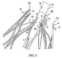
これまでに知られているステントでは、1つ又はそれ以上のトリガワイヤが、ステントの近位端22の頂点部39を通し、及び/又は遠位端24の頂点部69を通して配置されたかもしれない。送達のためにステントを圧縮させるとき、トリガワイヤが頂点部39と69を通して配置されていたなら、トリガワイヤはステントの支柱に押し付けられて挟まれた状態になり、ステント支柱及び/又はトリガワイヤ自体が傷つけられる可能性がある。以下に説明されている様に、本実施形態は、1つ又はそれ以上のトリガワイヤをステント20に連結するのに異なる手法を利用している。 In previously known stents, one or more trigger wires may have been placed through the apex 39 of the stent
引き続き図1と図2に関し、少なくとも一対の隣接する近位尖端部22aと22bは、異なる特徴を備えている。例えば、図2に示されている様に、第1近位尖端部22aは、穴31が形成されている端領域30を備えていてもよく、穴31は、トリガワイヤ84を受け入れるように構成されている。第2の隣接する近位尖端部22bは、図1と図2に示されている様に、一体型逆棘42が形成されている端領域40を備えている。しかしながら、第2近位尖端部22bは、図2に示され以下に説明されている様に、トリガワイヤを使って拘束されるようには構成されていない。以下に詳しく説明されている様に、ここに示されている異なる特徴を有する隣接する近位尖端部22aと22bを使用することによって、改良されたトリガワイヤの取り付けを実現することができ、逆棘の絡み付きを減らすことができる。 With continued reference to FIGS. 1 and 2, at least one pair of adjacent
以上に述べられている様に、ステント20は、第2近位尖端部22bの端領域40のうちの少なくとも1つに配置されている1つ又はそれ以上の逆棘42を備えていてもよい。逆棘42は、所望の逆棘形状を端領域40にレーザーカットすることによって形成されてもよい。スリット41は、従って、図1と図2に示されている様に、所望の逆棘形状が形成された後に各端領域40に形成される。一旦、所望の逆棘形状が切り出されると、逆棘42の本体は、端領域40に対して半径方向に外向きの方向に曲げられてもよい。その角度は、何らかの鋭角であってもよいし、代わりに、実質的に直角又は鈍角であってもよい。所望であれば、逆棘42は、目標組織部位での係合をやり易くするため、例えば逆棘の先端を研磨することによって尖らされてもよい。 As described above, the
引き続き図1に関し、ステント20は近位尖端部と遠位尖端部の間に配置されている少なくとも1つの支柱区間を備えていてもよい。例えば、複数の傾斜支柱区間が、第1近位尖端部22aとそれに対応する遠位尖端部62aの間に配置されていて、傾斜支柱区間の同一セットが、隣接する第2近位尖端部22bとそれに対応する遠位尖端部62bの間に配置されていてもよい。一例として、図1に示されている様に、第1近位尖端部22aは、遠位方向に伸張し、第1傾斜支柱区間57と第2傾斜支柱区間58それぞれに分岐し、それにより近位頂点部39を形成している。圧縮状態では、第1傾斜支柱区間57と第2傾斜支柱区間58は、それらが互いに実質的に平行になるように圧縮させることができる。図1に示されている展開状態では、第1傾斜支柱区間57と第2傾斜支柱区間58は、ステント20の長手方向軸線Lに対して或る角度に配置されている。展開状態では、第1傾斜支柱区間57と第2傾斜支柱区間58は、図1に描かれている様に、ステント20の長手方向軸線Lに対して約20−60度の角度に配置されていてもよい。 With continued reference to FIG. 1, the
同様に、それぞれの遠位尖端部62aは、近位方向に伸張し、第1傾斜支柱区間67と第2傾斜支柱区間68それぞれに分岐し、それにより遠位頂点部69を形成していてもよい。近位尖端部22aの第1傾斜支柱区間57と遠位尖端部62aの第1傾斜支柱区間67それぞれは、隣接する近位尖端部22bの第2傾斜支柱区間58と遠位尖端部62bの第2傾斜支柱区間68それぞれと交わり、それにより移行領域50を形成していてもよい。この様にして、ステント20は図1に示されている様に連続する略円筒形の形状に形成されていてもよい。 Similarly, each distal tip 62a may extend proximally and branch into a first inclined strut section 67 and a second
ステント20の展開は、少なくとも部分的には傾斜支柱区間57、58、67、及び68によってもたらされ、それら傾斜区間は、圧縮状態では互いに実質的に平行にさせることができ、且つ図1に示されている展開状態では外向きに互いから離れるように撓む傾向があってもよい。以下に詳しく説明されている様に、ステント20は、如何なる適した材料から形成されていてもよく、レーザーカットされたニチノールカニューレから形成されているのが望ましい。ステント20は、ニチノールから製造されている場合、送達シースが取り外されると、図1に示されている展開状態を取ることができる。 Deployment of the
それぞれの移行領域50は、図1に示されている様に、ステント20の長手方向軸Lに実質的に平行である方向に向いていてもよい。更に、それぞれの移行領域50は、移行領域が実質的に複数の異なる傾斜区間57、58、67、及び68が中央の場所で交わって構成されているので、傾斜区間に比べてより広い表面積を備えていてもよい。 Each
引き続き図1に関し、ステント20は、移行領域50のうちの少なくとも1つに配置されている少なくとも1つの逆棘52を備えていてもよい。逆棘52は、支柱の一部として一体的に形成されていてもよいし、移行領域50の表面に接着されている外付逆棘を備えていてもよい。図1に示されている様に、複数の一体型逆棘52が設けられているのが望ましい。逆棘52は、所望の逆棘形状を移行領域50にレーザーカットすることによって形成されていてもよい。このやり方では、逆棘は移行領域50と一体化している。スリット51は、従って、図1に示されている様に、所望の逆棘形状が形成された後に移行領域50に形成される。移行領域50はステント20の他の領域に比べて広くなった表面積を備えることができるので、ステントの構造的完全性に悪影響を与えること無く、より簡単に移行領域50の部分を穿孔することができる。一旦、所望の逆棘形状が切り出されると、逆棘52の本体は、移行領域50に対して何れかの角度で外向きの方向に曲げられてもよく、随意的には、目標組織部位で係合させ易くするために尖らされてもよい。 With continued reference to FIG. 1, the
遠位尖端部62aと62bのそれぞれは、図1に示されている様に、穴61が形成されている端領域60を備えていてもよい。ステント20の遠位端24は、グラフト材料(図示せず)の近位端に連結されてもよい。遠位尖端部62aと62bは、例えば、1つ又はそれ以上の縫合糸を使用し、その縫合糸をグラフト材料とステント20の穴61を通して輪にして、グラフト材料に連結されてもよい。このやり方では、ステント20を脈管内グラフト固定のための取り付けステントとして使用することができる。例えば、動脈瘤への流体の流入を封じるためにグラフト材料を動脈瘤と重ね合わせ、一方、ステント20の近位端22をグラフト材料から離れるように近位方向に伸張させて、例えば動脈瘤の病変部分から離れた脈管壁の正常部分に係合させるようにしてもよい。 Each of the
ステント20は、脈管又は管道内の目標場所まで前進させられるように、縮小直径送達状態を有している。ステント20は、例えば、通路内の開通性を維持する又はグラフトのルーメンを開存した状態に保持するため、脈管又は管道の少なくとも一部分に半径方向外向きの力を加えるよう展開した配備状態も有している。展開した状態では、流体の流れは、ステント20の中央ルーメンを通ることが許容されている。更に、ステント20の支柱は、実質的に平坦なワイヤ輪郭を備えていてもよいし、丸みの付いた輪郭を備えていてもよい。図2に最も分かり易く示されている様に、ステント20の支柱は、一般的に、平坦なワイヤ輪郭を備えている。
ステント20は、超弾性材料から作られていてもよい。単に一例として、超弾性材料は、ニッケルチタン合金(ニチノール)の様な形状記憶合金を備えていてもよい。ステント20がニチノールの様な自己展開性材料を備えている場合は、ステントは所望の展開状態に加熱硬化させることができ、それによれば、ステント20に弛緩形態を取らせ、そこに或る特定の低温又は高温媒体が加えられるとステントは事前に設定されている最初の展開時内径を取ることができる。代わりに、ステント20は、配備されると、材料に圧縮による永久的な歪みを生じさせること無くその元の展開形態に戻れるようになる他の金属及び合金から作られていてもよい。単に一例として、ステント20は、ステンレス鋼、コバルト−クロム合金、アモルファス金属、タンタル、白金、金、及びチタンの様な他の材料を備えていてもよい。ステント20は、また、熱可塑性ポリマー又は他のポリマーの様な非金属材料から作られていてもよい。 The
次に図2に関し、ステント20は、押し込み部材80と複数のトリガワイヤ84を使って、圧縮形態で目標部位に送達することができる。図2では、代表的な押し込み部材80は、本体81と、本体81より近位に配置されているテーパ領域82を備えている。テーパ領域82は、比較的小さい直径の近位領域が非外傷性アクセス及び送達を可能にするように、近位場所のより小さい直径へと続けて移行していてもよい。複数のトリガワイヤ84は、本体81の領域内に配置されていて、押し込み部材80の長さに亘っていてもよい。トリガワイヤ84はまた、随意的な係止用の特徴を備えた1つ又は複数のハンドルを操縦することによって作動し、ステント20の近位端22の配備を制御してもよい。 With reference now to FIG. 2, the
単一のトリガワイヤ84は、送達時にステント20を拘束するため、第1近位尖端部22aのうちの選択された尖端部の穴31を通して輪にすることができる。トリガワイヤは、逆棘42を備えている第2近位尖端部22bには連結されない。図示の実施形態では、トリガワイヤ84は、図2に見られる様に交互に配置されている近位尖端部のみを通して配置されている。それぞれの第1近位尖端部22aの様な第1近位尖端部のうちの選択された尖端部を拘束することによって、隣接する第2近位尖端部22bもまた送達時に間接的に半径方向内向きに引っ張られてもよい。ステント20の構成、特に移行領域50で交わる傾斜区間57、58、67、及び68の構成は、隣接する第2近位尖端部22bの間接的な圧縮をやり易くする。送達時に近位尖端部のうちの選択された尖端部だけが拘束されるので、トリガワイヤの数を減らすことができるのが好都合である。更に、図2に描かれている様に、逆棘42は、一つおきの尖端部にしか配置されていないので、逆棘の絡み付きを減らす又は無くすことができる。 A
ステント20の設計と関係付けられるもう1つの利点は、トリガワイヤ84が、頂点部39を通して配置されるのとは対照的に、第1近位尖端部22aの穴31のみを通して配置されていることである。従って、ステント20の圧縮中に、トリガワイヤ84が損傷を来す可能性は低くなり得る。また、トリガワイヤ84は第1近位尖端部22aの穴31内に隔離されているので、ステント支柱自体が損傷を来す可能性も低くなる。 Another advantage associated with the design of the
次に図3から図6に関し、もう1つのステント設計を説明する。図3では、ステント120は同様に、連続する円筒体にレーザー又は化学エッチングによってパターンを切り出し、円筒体の壁にスリットを作り出すことによって製造されてもよい。得られた構造を、その後、加熱硬化させて、それに所望の最終構成を付与するようにしてもよい。好適な最終構成は、図3に全体的に示されている様に、一連の近位尖端部と一連の遠位尖端部を有する形状を含んでいる。従って、図3に示されている様に、ステント120の近位端122は複数の隣接する近位尖端部122aと122bを備え、ステント20の遠位端124は複数の隣接する遠位尖端部162aと162bを備えてもよい。隣接する近位尖端部122aと122bの1つ又はそれ以上の対は、異なる特徴を備えていてもよい。例えば、第1近位尖端部122aは、第1穴131が形成されている端領域130を備えていてもよく、この第1穴131は、図5と図6に示されている様にトリガワイヤ184を受け入れるように構成されている。第2の、隣接する近位尖端部122bは、図3から図6に示されている様に、一体型逆棘142が形成されている端領域140を備えている。第2近位尖端部122bにも、図4に最も分かり易く示されている様に第2穴145が形成されており、その穴は、図5と図6に関連付けて説明され示されている様に、隣接する第1近位尖端部122aと同じトリガワイヤ184を受け入れるように構成されている。以下に詳しく説明されている様に、ここに示されている異なる特徴を有する隣接する近位尖端部122aと122bを使用することによって、改良されたトリガワイヤ取り付けを実現することができ、逆棘の絡み付きを減らすことができる。 Another stent design will now be described with respect to FIGS. In FIG. 3, the
第2近位尖端部122bのそれぞれは、図4に示されている様に、第1領域147と第2領域148を備えていてもよい。図4に示されている様に、第2近位尖端部122bそれぞれには、一般的には第1領域147に単一の逆棘142が配置され、一方、一般的には第2領域148に第2穴145が配置されていてもよい。逆棘142は、ステント20に関連付けて以上に概ね説明されている様に、所望の逆棘形状を端領域140にレーザーカットし、それによりスリット141を形成することによって形成されてもよい。一旦、所望の逆棘形状が切り出されると、逆棘142の本体は、以上に概ね説明されている様に、半径方向に外向きの方向に曲げられてもよく、また随意的に尖らされてもよい。 Each of the second
第2近位尖端部122bは、更に、図4に最も分かり易く示されている様に、第2穴145より遠位の場所に陥凹部分149が形成されていてもよい。以下に詳しく説明されている様に、ステント120の送達時、トリガワイヤが第1穴131と第2穴145を通して配置されたとき、第1近位尖端部122aは、第2近位尖端部122bに向けて引っ張られるように構成されていて、第2近位尖端部122bの陥凹部分149内に入れ子にすることができる。 The second
第1近位尖端部122aの第1穴131は、隣接する第2近位尖端部122bの第2穴145より僅かに遠位に配置されていてもよい。更に、図3に示されている様に、ステント120の遠位縁h0とそれぞれの近位尖端部122aの近位縁h1の間の第1長手方向距離L1は、ステントの遠位縁h0とそれぞれの陥凹部分149の遠位縁h2の間の第2長手方向距離L2より短くなっていてもよい。以下で図5と図6に関連付けて詳しく説明されている様に、この長さの差が、ステント送達時に第1近位尖端部122aを第2近位尖端部122bの陥凹部分149内に入れ子にし易くする。The
引き続き図3に関し、ステント120は、近位尖端部と遠位尖端部の間に配置されている少なくとも1つの支柱区間を備えていてもよい。1つの構成では、近位尖端部と遠位尖端部は互いと直接には整列していない。例えば、図3に示されている様に、近位尖端部122aと対応する遠位尖端部162aの間に第1傾斜区間157が配置され、同じ近位尖端部122aと隣接する遠位尖端部162bの間に第2傾斜区間158が配置されていてもよい。実際、それぞれの近位尖端部122aと122bは、遠位方向に伸張し、第1傾斜支柱区間157と第2傾斜支柱区間158それぞれに分岐し、それにより近位頂点部139を形成している。同様に、それぞれの遠位尖端部162aと162bは、近位方向に伸張し、第1傾斜支柱区間157と第2傾斜支柱区間158それぞれに分岐し、それにより遠位頂点部169を形成している。この様にして、ステント120は、図3に示されている様に連続する略円筒形状に形成されていてもよい。 With continued reference to FIG. 3, the
圧縮状態では、第1傾斜支柱区間157と第2傾斜支柱区間158は、それらが実質的に互いに平行になるように圧縮させることができる。図3に示されている展開状態では、第1傾斜支柱区間157と第2傾斜支柱区間158は、図3に示されている様に、ステント120の長手方向軸線Lに対して或る角度に配置されていてもよい。展開状態では、第1傾斜支柱区間157と第2傾斜支柱区間158は、ステント120の長手方向軸線Lに対して約20−60度の角度に配置されていてもよい。ステント120の展開は、少なくとも部分的には、傾斜支柱区間157と158によってもたらされ、それら傾斜支柱区間は、圧縮状態では実質的に互いに平行にさせることができ、且つ図3に示されている展開状態では外向きに互いから離れるように撓む傾向があってもよい。ステント120は、上に述べられているステント20と同様に、如何なる適した材料で形成されていてもよく、送達シースが取り外されると図3に示されている展開状態を取ることができるように、ニッケルチタン合金であるのが望ましい。 In the compressed state, the first
第1傾斜支柱区間157と第2傾斜支柱区間158は、遠位方向に互いに交わって遠位移行領域150を形成しており、同領域は、事実上、ステント120の遠位端領域160と同じである。それぞれの端領域160は、図3に示されている様に、ステント120の長手方向軸線Lに実質的に平行である方向を向いていてもよい。更に、それぞれの端領域160は、端領域160が実質的に複数の異なる傾斜区間157と158が一体に交わって構成されているので、傾斜区間に比べてより広い表面積を備えることもある。図3に示されている様に、端領域160に所望の逆棘形状をレーザーカットし、それによりスリット151を形成することによって、少なくとも1つの遠位逆棘152が一体的に形成されていてもよい。端領域160は、ステント120の他の領域に比べて広くなった表面積を備えることができるので、ステントの構造的完全性に悪影響を与えること無く、より簡単に端領域160の部分を穿孔することができる。更に、図3に示されている様に、遠位尖端部162aと162bのそれぞれの端領域160には縫合糸穴161が形成されていてもよい。ステント120の遠位端124は、グラフト材料(図示せず)の近位端に、上で図1−図2の実施形態に関連付けて概ね説明されている様に縫合糸を穴161及びグラフト材料を通して輪にすることによって連結することができる。 The first
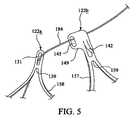
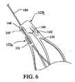
次に図5と図6に関し、ステント120は、図2の押し込み部材80の様な押し込み部材と複数のトリガワイヤを使用して、圧縮形態で目標部位に送達させることができる。1つの態様によれば、トリガワイヤ184は、それぞれの第1近位尖端部122aの第1穴131を通され、更に、隣接する第2近位尖端部122bの第2穴を通して輪にされてもよい。従って、送達時はそれぞれ個別のトリガワイヤが2つの別々の隣接する近位尖端部を拘束することもある。ステント120が図6に描かれている様に十分に圧縮されているときは、隣接する第1近位尖端部122aと第2近位尖端部122bは、互いに密接に引き寄せられることになる。長さL1とL2の差により、それぞれの近位尖端部122aを、図6に示されている様に、実質的に近位尖端部122bの第2領域148より遠位の陥凹部分149に入れ子にすることができる。更に、ステントの送達時、単一のトリガワイヤ184が第1穴と第2穴を通して配置されたとき、第1穴131は第2穴145より遠位に、第1穴131と第2穴145が実質的に互いと長手方向に整列するようにして配置されることになる。5 and 6,
ステント120の2つの別々の隣接する尖端部を拘束するのに単一のトリガワイヤを使用することができるのが好都合である。更に、トリガワイヤ184は、穴131と145だけを通して配置され、頂点部139の周りには配置されていないので、ステント120の圧縮中に、トリガワイヤが損傷を来す可能性は低くなることもある。また、トリガワイヤ184は穴131と145の内に隔離されているので、ステント支柱自体が損傷を来す可能性も低くなる。 Conveniently, a single trigger wire can be used to constrain two separate adjacent tips of the
次に図7に関し、遠位尖端部162aと162bの1つ又はそれ以上は随意的に造影穴190を備えていてもよく、その造影穴は、縫合糸穴161と逆棘スリット151の間に配置されていてもよい。造影穴190は、金マーカーの様な何らかの適した放射線不透過マーカーを受け入れることができる。造影穴190及び関係付けられている放射線不透過マーカーは、交互に配置されている遠位尖端部、例えば遠位尖端部162aだけに設けられているのが望ましい。代わりに、造影穴190は、それぞれの遠位尖端部162aと162bに配置されていてもよいし、ステントの周囲に沿って3つおき又は4つおきの尖端部に配置されていてもよい。造影穴190は、斜角を付けられていてもよいし、代わりに端領域160の支柱に実質的に直交していてもよい。 Referring now to FIG. 7, one or more of the
例えば、ステント120が脈管内グラフト固定に使用される場合、使用時、造影穴190をグラフト材料の遠位縁と整列させてもよい。より具体的には、縫合糸穴161をグラフト材料の近位領域と重なり合わせれば、それにより、縫合糸がステント120をグラフト材料に或る望ましい重なり度を持たせて連結できるようになる。従って、グラフト材料の近位縁は造影穴190と整列することができる。医師は、造影穴190の放射線不透過マーカーの位置を視認することができるので、グラフト材料の近位縁がどこに置かれているかが正確に分かるのが好都合であり得る。従って、誤ってグラフト材料を分岐脈管又は別の望ましくない場所と重ね合わせてしまう可能性を減らすことができる。 For example, if the
本発明の様々な実施形態を説明してきたが、本発明は、付随の特許請求の範囲及びそれらの等価物に照らして見た場合を除き、限定されない。更に、ここに記載されている利点は必ずしも本発明の唯一の利点というわけではなく、また必ずしも本発明のあらゆる実施形態が、記載されている利点の全てを実現できるものと期待されているわけではない。 While various embodiments of the invention have been described, the invention is not limited except when viewed in light of the appended claims and their equivalents. Further, the advantages described herein are not necessarily the only advantages of the present invention, and not every embodiment of the present invention is expected to be able to realize all of the described advantages. Absent.
本出願が優先権を主張している米国特許出願第61/027,192号及び同出願に付随する要約書の開示を、参考文献としてここに援用する。 The disclosures of US patent application Ser. No. 61 / 027,192, to which this application claims priority, and the abstract accompanying the application are incorporated herein by reference.
20 ステント
22 近位端
22a、22b 近位尖端部
24 遠位端
30、40 端領域
31 穴
39 近位端の頂点部
41、51 スリット
42、52 逆棘
50 移行領域
57、67 第1傾斜支柱区間
58、68 第2傾斜支柱区間
60 遠位先端部の端領域
61 穴
62a、62b 遠位尖端部
69 遠位端の頂点部
80 押し込み部材
81 本体
82 テーパ領域
84 トリガワイヤ
120 ステント
122 ステントの近位端
122a 第1近位尖端部
122b 第2近位尖端部
124 ステントの遠位端
130 端領域
131 第1穴
139 近位頂点部
140 端領域
141 スリット
142 逆棘
145 第2穴
147 近位尖端部の第1領域
148 近位尖端部の第2領域
149 陥凹部分
150 遠位移行領域
151 スリット
152 遠位逆棘
157 第1傾斜支柱区間
158 第2傾斜支柱区間
160 遠位端領域
161 縫合糸穴
162a、162b 遠位尖端部
169 遠位頂点部
184 トリガワイヤ
190 造影穴
h0 ステントの遠位縁
h1 近位尖端部の近位縁
h2 陥凹部分の遠位縁
L ステントの長手方向軸線
L1 h0とh1の間の長手方向距離
L2 h0とh2の間の長手方向距離20
Claims (20)
Translated fromJapanese前記ステントの近位端に配置されている一連の近位尖端部と、
前記ステントの遠位端に配置されている一連の遠位尖端部と、
近位尖端部と遠位尖端部の間に配置されている少なくとも1つの支柱区間であって、前記ステントを圧縮状態から配備状態へ展開させることのできる支柱区間と、を含んでおり、
前記一連の近位尖端部は、交互に配置されている第1近位尖端部と第2近位尖端部を備えており、前記第1近位尖端部のそれぞれは、穴を有する端領域を含んでおり、前記第2近位尖端部のそれぞれは、組織に係合するための少なくとも1つの逆棘を備えている、ステント。In stents for use in medical procedures,
A series of proximal tips disposed at the proximal end of the stent;
A series of distal tips disposed at the distal end of the stent;
At least one strut section disposed between the proximal tip and the distal tip, the strut section capable of deploying the stent from a compressed state to a deployed state;
The series of proximal cusps includes alternating first and second proximal cusps, each of the first proximal cusps having an end region having a hole. A stent, wherein each of the second proximal tips comprises at least one barb for engaging tissue.
前記第1近位尖端部のそれぞれが、複数のトリガワイヤにより直接拘束されること、
前記第2近位尖端部の前記逆棘が、前記第2近位尖端部の端領域に一体的に形成されていること、
複数の傾斜支柱区間が、それぞれの近位尖端部とそれぞれの遠位尖端部の間に配置されていること、及び
前記遠位尖端部のそれぞれが、前記ステントの遠位端をグラフト材料に連結するための縫合糸を受け入れるための穴が設けられている端領域を含んでいること、のうち2つ又はそれ以上を含んでいる、上記請求項の何れかに記載のステント。The following matters:
Each of the first proximal tips is directly constrained by a plurality of trigger wires;
The barbs of the second proximal tip are integrally formed in the end region of the second proximal tip;
A plurality of inclined strut sections are disposed between each proximal tip and each distal tip, and each of the distal tips connects the distal end of the stent to the graft material A stent according to any preceding claim, including two or more of the end regions provided with holes for receiving sutures to do.
前記ステントの近位端に配置されている一連の近位尖端部と、
前記ステントの遠位端に配置されている一連の遠位尖端部と、
近位尖端部と遠位尖端部の間に配置されている少なくとも1つの支柱区間であって、前記ステントを圧縮状態から配備状態へ展開させることのできる支柱区間と、を含んでおり、
前記一連の近位尖端部は、交互に配置されている第1近位尖端部と第2近位尖端部を含んでおり、前記第1近位尖端部のそれぞれは、第1穴が設けられている端領域を含み、前記第2近位尖端部のそれぞれは、第2穴を含んでおり、
前記第1近位尖端部のうちの少なくとも1つは、前記ステントの送達時に隣接する第2近位尖端部と同時に一体に拘束される、ステント。In stents for use in medical procedures,
A series of proximal tips disposed at the proximal end of the stent;
A series of distal tips disposed at the distal end of the stent;
At least one strut section disposed between the proximal tip and the distal tip, the strut section capable of deploying the stent from a compressed state to a deployed state;
The series of proximal cusps includes alternating first and second proximal cusps, each of the first proximal cusps having a first hole. Each of the second proximal tips includes a second hole;
A stent wherein at least one of the first proximal tips is constrained together at the same time as the adjacent second proximal tip during delivery of the stent.
前記第2近位尖端部が、第1領域と第2領域を含んでおり、前記第1領域には少なくとも1つの一体型逆棘が形成され、前記第2領域には前記第2穴が形成されていること、
前記第2近位尖端部の前記第2穴より遠位の場所に、陥凹部分が形成されており、前記第1近位尖端部は、前記第2近位尖端部に向けて引っ張られて、前記第2近位尖端部の前記陥凹部分内に入れ子になるように構成されていること、
前記第1穴が前記第2穴より遠位に配置されており、前記ステントの送達時、単一のトリガワイヤが前記第1穴と前記第2穴を通して配置されたとき、前記第1穴と前記第2穴は互いに実質的に長手方向に整列して配置されること、
前記遠位尖端部のそれぞれが、前記ステントの遠位端をグラフト材料に連結するための縫合糸を受け入れるための縫合糸穴が設けられている端領域を含んでいること、
前記遠位尖端部のそれぞれが、放射線不透過マーカーを受け入れる働きをする造影穴を含んでおり、前記造影穴は、前記縫合糸穴より近位に配置されていて、前記造影穴は、前記グラフト材料の近位縁と整列させることができること、及び
前記遠位尖端部のそれぞれが、前記ステントの遠位端をグラフト材料に連結するための縫合糸を受け入れるように設計されている縫合糸穴が設けられている端領域を含んでいること、のうち2つ又はそれ以上を含んでいる、請求項8から15の何れかに記載のステント。The following matters:
The second proximal apex includes a first region and a second region, wherein the first region is formed with at least one integral barb and the second region is formed with the second hole. is being done,
A recessed portion is formed at a location distal to the second hole of the second proximal tip, and the first proximal tip is pulled toward the second proximal tip. , Configured to be nested within the recessed portion of the second proximal apex,
The first hole is disposed distal to the second hole, and when the stent is delivered, when a single trigger wire is disposed through the first hole and the second hole, the first hole and the The second holes are arranged substantially longitudinally aligned with each other;
Each of the distal tips includes an end region provided with a suture hole for receiving a suture for connecting the distal end of the stent to a graft material;
Each of the distal tips includes a contrast hole that serves to receive a radiopaque marker, the contrast hole being disposed proximal to the suture hole, and the contrast hole is defined as the graft hole. A suture hole that can be aligned with a proximal edge of the material, and each of the distal tips is designed to receive a suture for connecting the distal end of the stent to a graft material; 16. A stent according to any of claims 8 to 15, comprising two or more of the end regions provided.
前記ステントの近位端に配置されている一連の近位尖端部と、
前記ステントの遠位端に配置されている一連の遠位尖端部と、
近位尖端部と遠位尖端部の間に配置されている少なくとも1つの支柱区間であって、前記ステントを圧縮状態から配備状態へ展開させることのできる支柱区間と、を含んでおり、
前記一連の近位尖端部は、複数の交互に配置されている第1近位尖端部と第2近位尖端部を含んでおり、前記第1近位尖端部のそれぞれは、第1穴を有する端領域を含んでおり、
前記第2近位尖端部のそれぞれは、第1領域と第2領域を含んでおり、前記第1領域には少なくとも1つの一体型逆棘が形成され、前記第2領域には第2穴が形成されており、前記第2近位尖端部のそれぞれは、前記第2近位尖端部の前記第2穴より遠位の場所に形成されている陥凹部分を含んでおり、
前記第1近位尖端部のうちの少なくとも1つは、前記ステントの送達時に隣接する第2近位尖端部の前記陥凹部分内に入れ子にされる、ステント。In stents for use in medical procedures,
A series of proximal tips disposed at the proximal end of the stent;
A series of distal tips disposed at the distal end of the stent;
At least one strut section disposed between the proximal tip and the distal tip, the strut section capable of deploying the stent from a compressed state to a deployed state;
The series of proximal cusps includes a plurality of alternating first and second proximal cusps, each of the first proximal cusps having a first hole. Including an end region having
Each of the second proximal tips includes a first region and a second region, wherein the first region is formed with at least one integral barb, and the second region has a second hole. Each of the second proximal cusps includes a recessed portion formed at a location distal to the second hole of the second proximal cusp;
A stent wherein at least one of the first proximal tips is nested within the recessed portion of an adjacent second proximal tip during delivery of the stent.
Applications Claiming Priority (3)
| Application Number | Priority Date | Filing Date | Title |
|---|---|---|---|
| US2719208P | 2008-02-08 | 2008-02-08 | |
| US61/027,192 | 2008-02-08 | ||
| PCT/US2009/000747WO2009099632A2 (en) | 2008-02-08 | 2009-02-06 | Stent designs for use with one or more trigger wires |
Publications (3)
| Publication Number | Publication Date |
|---|---|
| JP2011510788Atrue JP2011510788A (en) | 2011-04-07 |
| JP2011510788A5 JP2011510788A5 (en) | 2012-03-22 |
| JP5559063B2 JP5559063B2 (en) | 2014-07-23 |
Family
ID=40848530
Family Applications (1)
| Application Number | Title | Priority Date | Filing Date |
|---|---|---|---|
| JP2010545876AActiveJP5559063B2 (en) | 2008-02-08 | 2009-02-06 | Stent design for use with one or more trigger wires |
Country Status (6)
| Country | Link |
|---|---|
| US (3) | US8163007B2 (en) |
| EP (1) | EP2237749B1 (en) |
| JP (1) | JP5559063B2 (en) |
| AU (1) | AU2009210732B2 (en) |
| CA (1) | CA2711849C (en) |
| WO (1) | WO2009099632A2 (en) |
Cited By (2)
| Publication number | Priority date | Publication date | Assignee | Title |
|---|---|---|---|---|
| JP2012232132A (en)* | 2011-04-28 | 2012-11-29 | Cook Medical Technologies Llc | Stent and stent-graft |
| JP2016518948A (en)* | 2013-05-20 | 2016-06-30 | エドワーズ ライフサイエンシーズ コーポレイションEdwards Lifesciences Corporation | Prosthetic heart valve delivery device |
Families Citing this family (56)
| Publication number | Priority date | Publication date | Assignee | Title |
|---|---|---|---|---|
| JP4812316B2 (en)* | 2005-03-16 | 2011-11-09 | イビデン株式会社 | Honeycomb structure |
| US7914569B2 (en)* | 2005-05-13 | 2011-03-29 | Medtronics Corevalve Llc | Heart valve prosthesis and methods of manufacture and use |
| US8163007B2 (en) | 2008-02-08 | 2012-04-24 | Cook Medical Technologies Llc | Stent designs for use with one or more trigger wires |
| US7655037B2 (en)* | 2008-04-17 | 2010-02-02 | Cordis Corporation | Combination barb restraint and stent attachment deployment mechanism |
| US8394139B2 (en) | 2008-08-29 | 2013-03-12 | Cook Medical Technologies Llc | Barbed anchors for wire stent |
| GB2464977B (en) | 2008-10-31 | 2010-11-03 | William Cook Europe As | Introducer for deploying a stent graft in a curved lumen and stent graft therefor |
| US11376114B2 (en) | 2008-10-31 | 2022-07-05 | Cook Medical Technologies Llc | Introducer for deploying a stent graft in a curved lumen and stent graft therefor |
| US8523932B2 (en) | 2010-05-24 | 2013-09-03 | Cook Medical Technologies Llc | Variable diameter trigger wire |
| USD653343S1 (en) | 2010-09-20 | 2012-01-31 | St. Jude Medical, Inc. | Surgical cuff |
| USD660433S1 (en)* | 2010-09-20 | 2012-05-22 | St. Jude Medical, Inc. | Surgical stent assembly |
| USD652927S1 (en)* | 2010-09-20 | 2012-01-24 | St. Jude Medical, Inc. | Surgical stent |
| USD653342S1 (en)* | 2010-09-20 | 2012-01-31 | St. Jude Medical, Inc. | Stent connections |
| USD652926S1 (en)* | 2010-09-20 | 2012-01-24 | St. Jude Medical, Inc. | Forked end |
| USD653341S1 (en)* | 2010-09-20 | 2012-01-31 | St. Jude Medical, Inc. | Surgical stent |
| USD654169S1 (en)* | 2010-09-20 | 2012-02-14 | St. Jude Medical Inc. | Forked ends |
| USD648854S1 (en)* | 2010-09-20 | 2011-11-15 | St. Jude Medical, Inc. | Commissure points |
| USD660967S1 (en)* | 2010-09-20 | 2012-05-29 | St. Jude Medical, Inc. | Surgical stent |
| USD654170S1 (en)* | 2010-09-20 | 2012-02-14 | St. Jude Medical, Inc. | Stent connections |
| USD660432S1 (en)* | 2010-09-20 | 2012-05-22 | St. Jude Medical, Inc. | Commissure point |
| USD684692S1 (en)* | 2010-09-20 | 2013-06-18 | St. Jude Medical, Inc. | Forked ends |
| US20130226282A1 (en)* | 2010-10-29 | 2013-08-29 | Medisourceplus Co., Ltd. | Stent wires, and method for manufacturing such stent wires and stents |
| JP6120373B2 (en)* | 2011-03-29 | 2017-04-26 | テルモ株式会社 | Stent and stent delivery system |
| US8920482B2 (en) | 2011-06-30 | 2014-12-30 | Cook Medical Technologies Llc | Stent delivery system |
| US8728148B2 (en) | 2011-11-09 | 2014-05-20 | Cook Medical Technologies Llc | Diameter reducing tie arrangement for endoluminal prosthesis |
| US9220620B2 (en) | 2011-11-22 | 2015-12-29 | Cook Medical Technologies Llc | Endoluminal prosthesis introducer |
| EP2604232B1 (en) | 2011-12-14 | 2021-02-24 | Cook Medical Technologies LLC | Circumferential trigger wire for deploying an endoluminal prosthesis |
| US9629737B2 (en) | 2011-12-23 | 2017-04-25 | Cook Medical Technologies Llc | Delivery system for staged stent release |
| US20150018933A1 (en)* | 2011-12-29 | 2015-01-15 | Beijing Percutek Therapeutics Co., Ltd. | Aortic stent-graft |
| US9737394B2 (en) | 2012-04-27 | 2017-08-22 | Medtronic Vascular, Inc. | Stent-graft prosthesis for placement in the abdominal aorta |
| US10098767B2 (en) | 2012-04-27 | 2018-10-16 | Medtronic Vascular, Inc. | Reconfigurable stent-graft delivery system and method of use |
| US8968384B2 (en) | 2012-04-27 | 2015-03-03 | Medtronic Vascular, Inc. | Circumferentially constraining sutures for a stent-graft |
| US9393140B2 (en) | 2012-04-27 | 2016-07-19 | Medtronic Vascular, Inc. | Reconfigurable stent-graft delivery system and method of use |
| US9452069B2 (en) | 2012-04-27 | 2016-09-27 | Medtronic Vascular, Inc. | Reconfigurable stent-graft delivery system and method of use |
| US9750626B2 (en) | 2012-10-31 | 2017-09-05 | Cook Medical Technologies Llc | Apparatus and methods for improved stent deployment |
| US9855129B2 (en)* | 2012-10-31 | 2018-01-02 | Cook Medical Technologies Llc | Multi-level suture attachments for coupling a stent to graft material |
| US9622893B2 (en) | 2012-12-20 | 2017-04-18 | Cook Medical Technologies Llc | Apparatus and method for improved deployment of endovascular grafts |
| US9675439B2 (en) | 2012-12-21 | 2017-06-13 | Cook Medical Technologies Llc | Stent designs for reduced infolding of graft material |
| US10039657B2 (en)* | 2012-12-21 | 2018-08-07 | CARDINAL HEALTH SWITZERLAND 515 GmbH | Cannulation guiding device for bifurcated stent and method of use |
| US10350096B2 (en) | 2012-12-26 | 2019-07-16 | Cook Medical Technologies Llc | Expandable stent-graft system having diameter reducing connectors |
| US9351860B2 (en) | 2013-03-14 | 2016-05-31 | Cook Medical Technologies Llc | Loading tool for capturing stent points |
| USD730521S1 (en)* | 2013-09-04 | 2015-05-26 | St. Jude Medical, Cardiology Division, Inc. | Stent with commissure attachments |
| USD730520S1 (en)* | 2013-09-04 | 2015-05-26 | St. Jude Medical, Cardiology Division, Inc. | Stent with commissure attachments |
| US11123205B2 (en) | 2013-09-24 | 2021-09-21 | Trivascular, Inc. | Tandem modular endograft |
| EP3107497B1 (en) | 2014-02-21 | 2020-07-22 | Edwards Lifesciences CardiAQ LLC | Delivery device for controlled deployment of a replacement valve |
| US9855155B2 (en)* | 2014-06-26 | 2018-01-02 | Cardinal Health Switzeerland 515 Gmbh | Endoprosthesis anchoring and sealing |
| CN104546242B (en)* | 2014-12-02 | 2017-01-25 | 先健科技(深圳)有限公司 | Delivery devices for implants and implanted medical devices |
| US10206801B2 (en) | 2014-12-29 | 2019-02-19 | Cook Medical Technologies Llc | Trigger wire arrangements for endografts |
| EP3250157B1 (en)* | 2015-01-28 | 2024-08-28 | Aortic Innovations, LLC | Modular endo-aortic device |
| US10583007B2 (en)* | 2015-12-02 | 2020-03-10 | Edwards Lifesciences Corporation | Suture deployment of prosthetic heart valve |
| WO2017196909A1 (en)* | 2016-05-12 | 2017-11-16 | St. Jude Medical, Cardiology Division, Inc. | Mitral heart valve replacement |
| US10709541B2 (en) | 2017-04-28 | 2020-07-14 | Cook Medical Technologies Llc | Systems and methods for adjusting the diameter of an endoluminal prosthesis and an endoluminal prosthesis configured for the same |
| US12427018B2 (en)* | 2020-05-11 | 2025-09-30 | St. Jude Medical, Cardiology Division, Inc. | Transcatheter mitral valve fixation concepts |
| GB2605559B (en) | 2021-01-07 | 2023-04-05 | Cook Medical Technologies Llc | Stent graft |
| CN113143348B (en)* | 2021-02-18 | 2025-02-28 | 宁波迪创医疗科技有限公司 | A stent system with a controllable release mechanism |
| CN120225147A (en)* | 2022-09-23 | 2025-06-27 | 里弗马克医疗公司 | Intraluminal stent with handle for treating benign prostatic hyperplasia |
| CN116549194B (en)* | 2023-07-07 | 2024-03-01 | 浙江归创医疗科技有限公司 | Conveying system support beam-contracting mechanism and abdominal aortic tectorial membrane support conveying system |
Citations (4)
| Publication number | Priority date | Publication date | Assignee | Title |
|---|---|---|---|---|
| US5383887A (en)* | 1992-12-28 | 1995-01-24 | Celsa Lg | Device for selectively forming a temporary blood filter |
| US20060036314A1 (en)* | 2003-03-27 | 2006-02-16 | Perez Juan I | Delivery system for endoluminal implant |
| JP2006271988A (en)* | 1995-06-07 | 2006-10-12 | Endovascular Technologies Inc | Intraluminal grafting system |
| DE202007005491U1 (en)* | 2007-04-13 | 2007-06-14 | Jenavalve Technology Gmbh | Medical device for treating aortic valve insufficiency of patient, has self-expandable endoprosthesis for positioning and fixing heart valve implant in arota of patient, and retaining segment with brackets for receiving implant |
Family Cites Families (38)
| Publication number | Priority date | Publication date | Assignee | Title |
|---|---|---|---|---|
| US7166125B1 (en)* | 1988-03-09 | 2007-01-23 | Endovascular Technologies, Inc. | Intraluminal grafting system |
| US5669936A (en)* | 1983-12-09 | 1997-09-23 | Endovascular Technologies, Inc. | Endovascular grafting system and method for use therewith |
| US6682557B1 (en)* | 1991-04-11 | 2004-01-27 | Endovascular Technologies, Inc. | Bifurcated multicapsule intraluminal grafting system and method |
| CA2065634C (en)* | 1991-04-11 | 1997-06-03 | Alec A. Piplani | Endovascular graft having bifurcation and apparatus and method for deploying the same |
| US5628783A (en)* | 1991-04-11 | 1997-05-13 | Endovascular Technologies, Inc. | Bifurcated multicapsule intraluminal grafting system and method |
| US5824044A (en)* | 1994-05-12 | 1998-10-20 | Endovascular Technologies, Inc. | Bifurcated multicapsule intraluminal grafting system |
| US5527355A (en)* | 1994-09-02 | 1996-06-18 | Ahn; Sam S. | Apparatus and method for performing aneurysm repair |
| US5843170A (en)* | 1994-09-02 | 1998-12-01 | Ahn; Sam Seunghae | Apparatus and method for performing aneurysm repair |
| US6814748B1 (en)* | 1995-06-07 | 2004-11-09 | Endovascular Technologies, Inc. | Intraluminal grafting system |
| JP4042998B2 (en)* | 1997-01-29 | 2008-02-06 | クック インコーポレイテッド | Bell bottom modular stent graft |
| US6849087B1 (en)* | 1999-10-06 | 2005-02-01 | Timothy A. M. Chuter | Device and method for staged implantation of a graft for vascular repair |
| US6808534B1 (en)* | 2000-02-16 | 2004-10-26 | Endovascular Technologies, Inc. | Collapsible jacket guard |
| US6517573B1 (en)* | 2000-04-11 | 2003-02-11 | Endovascular Technologies, Inc. | Hook for attaching to a corporeal lumen and method of manufacturing |
| US6361556B1 (en)* | 2000-04-27 | 2002-03-26 | Endovascular Tech Inc | System and method for endovascular aneurysm repair in conjuction with vascular stabilization |
| US7666221B2 (en)* | 2000-05-01 | 2010-02-23 | Endovascular Technologies, Inc. | Lock modular graft component junctions |
| US6454796B1 (en)* | 2000-05-05 | 2002-09-24 | Endovascular Technologies, Inc. | Vascular graft |
| US7708771B2 (en)* | 2002-02-26 | 2010-05-04 | Endovascular Technologies, Inc. | Endovascular graft device and methods for attaching components thereof |
| WO2004049982A2 (en)* | 2002-12-02 | 2004-06-17 | Gi Dynamics, Inc. | Bariatric sleeve |
| WO2004078065A2 (en)* | 2003-03-03 | 2004-09-16 | Sinus Rhythm Technologies, Inc. | Electrical conduction block implant device |
| US20040243221A1 (en)* | 2003-05-27 | 2004-12-02 | Fawzi Natalie V. | Endovascular graft including substructure for positioning and sealing within vasculature |
| US7651519B2 (en)* | 2003-09-16 | 2010-01-26 | Cook Incorporated | Prosthesis deployment system |
| EP3424463A1 (en)* | 2003-11-08 | 2019-01-09 | Cook Medical Technologies LLC | Aorta and branch vessel stent grafts and system |
| AU2004305450B2 (en)* | 2003-12-09 | 2009-01-08 | Gi Dynamics, Inc. | Intestinal sleeve |
| US8182528B2 (en)* | 2003-12-23 | 2012-05-22 | Sadra Medical, Inc. | Locking heart valve anchor |
| AU2005262541B2 (en)* | 2004-06-16 | 2011-04-21 | Cook Incorporated | Thoracic deployment device and stent graft |
| DE102004041259B4 (en)* | 2004-08-26 | 2008-03-06 | Osypka, Peter, Dr.-Ing. | Device for stiffening and relieving a vessel widening |
| EP1991168B1 (en)* | 2006-02-16 | 2016-01-27 | Transcatheter Technologies GmbH | Minimally invasive heart valve replacement |
| US7909863B2 (en)* | 2006-02-27 | 2011-03-22 | Cook Incorporated | Retention of exposed stent loops |
| US20100010622A1 (en)* | 2006-03-13 | 2010-01-14 | Abbott Laboratories | Hybrid segmented endoprosthesis |
| US8460364B2 (en)* | 2006-07-20 | 2013-06-11 | Orbusneich Medical, Inc. | Bioabsorbable polymeric medical device |
| JP5520432B2 (en) | 2006-10-03 | 2014-06-11 | 古河電気工業株式会社 | Manufacturing method of semiconductor transistor |
| US8092510B2 (en)* | 2007-07-25 | 2012-01-10 | Cook Medical Technologies Llc | Retention wire for self-expanding stent |
| US20090082845A1 (en)* | 2007-09-26 | 2009-03-26 | Boston Scientific Corporation | Alignment stent apparatus and method |
| US20090125096A1 (en)* | 2007-11-12 | 2009-05-14 | Medtronic Vascular, Inc. | Stent Graft With Pins |
| US7905915B2 (en)* | 2007-12-27 | 2011-03-15 | Cook Incorporated | Z-stent with incorporated barbs |
| US20090234429A1 (en)* | 2008-02-07 | 2009-09-17 | Lilip Lau | Self-restraining endoluminal prosthesis |
| US8163007B2 (en)* | 2008-02-08 | 2012-04-24 | Cook Medical Technologies Llc | Stent designs for use with one or more trigger wires |
| US8840659B2 (en)* | 2011-04-28 | 2014-09-23 | Cook Medical Technologies Llc | Stent and stent-graft designs |
- 2009
- 2009-02-02USUS12/364,162patent/US8163007B2/enactiveActive
- 2009-02-06AUAU2009210732Apatent/AU2009210732B2/enactiveActive
- 2009-02-06WOPCT/US2009/000747patent/WO2009099632A2/enactiveApplication Filing
- 2009-02-06EPEP09708866.0Apatent/EP2237749B1/enactiveActive
- 2009-02-06CACA2711849Apatent/CA2711849C/enactiveActive
- 2009-02-06JPJP2010545876Apatent/JP5559063B2/enactiveActive
- 2012
- 2012-03-26USUS13/429,983patent/US9833345B2/enactiveActive
- 2017
- 2017-11-16USUS15/814,952patent/US10363154B2/enactiveActive
Patent Citations (4)
| Publication number | Priority date | Publication date | Assignee | Title |
|---|---|---|---|---|
| US5383887A (en)* | 1992-12-28 | 1995-01-24 | Celsa Lg | Device for selectively forming a temporary blood filter |
| JP2006271988A (en)* | 1995-06-07 | 2006-10-12 | Endovascular Technologies Inc | Intraluminal grafting system |
| US20060036314A1 (en)* | 2003-03-27 | 2006-02-16 | Perez Juan I | Delivery system for endoluminal implant |
| DE202007005491U1 (en)* | 2007-04-13 | 2007-06-14 | Jenavalve Technology Gmbh | Medical device for treating aortic valve insufficiency of patient, has self-expandable endoprosthesis for positioning and fixing heart valve implant in arota of patient, and retaining segment with brackets for receiving implant |
Cited By (5)
| Publication number | Priority date | Publication date | Assignee | Title |
|---|---|---|---|---|
| JP2012232132A (en)* | 2011-04-28 | 2012-11-29 | Cook Medical Technologies Llc | Stent and stent-graft |
| JP2017056262A (en)* | 2011-04-28 | 2017-03-23 | クック・メディカル・テクノロジーズ・リミテッド・ライアビリティ・カンパニーCook Medical Technologies Llc | Stent and stent graft |
| JP2016518948A (en)* | 2013-05-20 | 2016-06-30 | エドワーズ ライフサイエンシーズ コーポレイションEdwards Lifesciences Corporation | Prosthetic heart valve delivery device |
| US10695176B2 (en) | 2013-05-20 | 2020-06-30 | Edwards Lifesciences Corporation | Prosthetic heart valve delivery apparatus |
| US12059348B2 (en) | 2013-05-20 | 2024-08-13 | Edwards Lifesciences Corporation | Prosthetic heart valve delivery apparatus |
Also Published As
| Publication number | Publication date |
|---|---|
| US9833345B2 (en) | 2017-12-05 |
| WO2009099632A3 (en) | 2009-10-01 |
| AU2009210732A1 (en) | 2009-08-13 |
| CA2711849A1 (en) | 2009-08-13 |
| EP2237749B1 (en) | 2015-04-08 |
| US10363154B2 (en) | 2019-07-30 |
| US20090204202A1 (en) | 2009-08-13 |
| US8163007B2 (en) | 2012-04-24 |
| US20180071122A1 (en) | 2018-03-15 |
| AU2009210732B2 (en) | 2013-02-21 |
| JP5559063B2 (en) | 2014-07-23 |
| EP2237749A2 (en) | 2010-10-13 |
| CA2711849C (en) | 2015-09-08 |
| US20120245676A1 (en) | 2012-09-27 |
| WO2009099632A2 (en) | 2009-08-13 |
Similar Documents
| Publication | Publication Date | Title |
|---|---|---|
| JP5559063B2 (en) | Stent design for use with one or more trigger wires | |
| JP6441297B2 (en) | Stent and stent graft | |
| US9629733B2 (en) | Stents having barbs protected during delivery | |
| US9370437B2 (en) | Stent having less invasive ends | |
| US8672992B2 (en) | Stent and stent-graft having one or more conformance struts | |
| US20090149946A1 (en) | Stent having at least one barb and methods of manufacture | |
| US10603155B2 (en) | Multi-level suture attachments for coupling a stent to graft material | |
| EP2745806B1 (en) | Stent designs for reduced infolding of graft material | |
| AU2014213580B2 (en) | Stent and stent-graft designs |
Legal Events
| Date | Code | Title | Description |
|---|---|---|---|
| A521 | Request for written amendment filed | Free format text:JAPANESE INTERMEDIATE CODE: A523 Effective date:20120201 | |
| A621 | Written request for application examination | Free format text:JAPANESE INTERMEDIATE CODE: A621 Effective date:20120201 | |
| A711 | Notification of change in applicant | Free format text:JAPANESE INTERMEDIATE CODE: A711 Effective date:20120608 | |
| A521 | Request for written amendment filed | Free format text:JAPANESE INTERMEDIATE CODE: A821 Effective date:20120608 | |
| A977 | Report on retrieval | Free format text:JAPANESE INTERMEDIATE CODE: A971007 Effective date:20130711 | |
| A131 | Notification of reasons for refusal | Free format text:JAPANESE INTERMEDIATE CODE: A131 Effective date:20130717 | |
| A521 | Request for written amendment filed | Free format text:JAPANESE INTERMEDIATE CODE: A523 Effective date:20131015 | |
| A711 | Notification of change in applicant | Free format text:JAPANESE INTERMEDIATE CODE: A711 Effective date:20131227 | |
| A521 | Request for written amendment filed | Free format text:JAPANESE INTERMEDIATE CODE: A821 Effective date:20131227 | |
| TRDD | Decision of grant or rejection written | ||
| A01 | Written decision to grant a patent or to grant a registration (utility model) | Free format text:JAPANESE INTERMEDIATE CODE: A01 Effective date:20140513 | |
| A61 | First payment of annual fees (during grant procedure) | Free format text:JAPANESE INTERMEDIATE CODE: A61 Effective date:20140605 | |
| R150 | Certificate of patent or registration of utility model | Ref document number:5559063 Country of ref document:JP Free format text:JAPANESE INTERMEDIATE CODE: R150 | |
| R250 | Receipt of annual fees | Free format text:JAPANESE INTERMEDIATE CODE: R250 | |
| R250 | Receipt of annual fees | Free format text:JAPANESE INTERMEDIATE CODE: R250 | |
| R250 | Receipt of annual fees | Free format text:JAPANESE INTERMEDIATE CODE: R250 | |
| R250 | Receipt of annual fees | Free format text:JAPANESE INTERMEDIATE CODE: R250 | |
| R250 | Receipt of annual fees | Free format text:JAPANESE INTERMEDIATE CODE: R250 | |
| R250 | Receipt of annual fees | Free format text:JAPANESE INTERMEDIATE CODE: R250 | |
| R250 | Receipt of annual fees | Free format text:JAPANESE INTERMEDIATE CODE: R250 | |
| R250 | Receipt of annual fees | Free format text:JAPANESE INTERMEDIATE CODE: R250 | |
| R250 | Receipt of annual fees | Free format text:JAPANESE INTERMEDIATE CODE: R250 |