JP2011510739A - Thrombus removal device, thrombus removal system, and thrombus removal method - Google Patents
Thrombus removal device, thrombus removal system, and thrombus removal methodDownload PDFInfo
- Publication number
- JP2011510739A JP2011510739AJP2010544922AJP2010544922AJP2011510739AJP 2011510739 AJP2011510739 AJP 2011510739AJP 2010544922 AJP2010544922 AJP 2010544922AJP 2010544922 AJP2010544922 AJP 2010544922AJP 2011510739 AJP2011510739 AJP 2011510739A
- Authority
- JP
- Japan
- Prior art keywords
- thrombectomy
- patient
- thrombus
- thrombectomy device
- energy
- Prior art date
- Legal status (The legal status is an assumption and is not a legal conclusion. Google has not performed a legal analysis and makes no representation as to the accuracy of the status listed.)
- Granted
Links
Images


Classifications
- B—PERFORMING OPERATIONS; TRANSPORTING
- B01—PHYSICAL OR CHEMICAL PROCESSES OR APPARATUS IN GENERAL
- B01D—SEPARATION
- B01D46/00—Filters or filtering processes specially modified for separating dispersed particles from gases or vapours
- B01D46/66—Regeneration of the filtering material or filter elements inside the filter
- B01D46/68—Regeneration of the filtering material or filter elements inside the filter by means acting on the cake side involving movement with regard to the filter elements
- A—HUMAN NECESSITIES
- A61—MEDICAL OR VETERINARY SCIENCE; HYGIENE
- A61F—FILTERS IMPLANTABLE INTO BLOOD VESSELS; PROSTHESES; DEVICES PROVIDING PATENCY TO, OR PREVENTING COLLAPSING OF, TUBULAR STRUCTURES OF THE BODY, e.g. STENTS; ORTHOPAEDIC, NURSING OR CONTRACEPTIVE DEVICES; FOMENTATION; TREATMENT OR PROTECTION OF EYES OR EARS; BANDAGES, DRESSINGS OR ABSORBENT PADS; FIRST-AID KITS
- A61F2/00—Filters implantable into blood vessels; Prostheses, i.e. artificial substitutes or replacements for parts of the body; Appliances for connecting them with the body; Devices providing patency to, or preventing collapsing of, tubular structures of the body, e.g. stents
- A61F2/0004—Closure means for urethra or rectum, i.e. anti-incontinence devices or support slings against pelvic prolapse
- A61F2/0031—Closure means for urethra or rectum, i.e. anti-incontinence devices or support slings against pelvic prolapse for constricting the lumen; Support slings for the urethra
- A61F2/0036—Closure means for urethra or rectum, i.e. anti-incontinence devices or support slings against pelvic prolapse for constricting the lumen; Support slings for the urethra implantable
- A—HUMAN NECESSITIES
- A61—MEDICAL OR VETERINARY SCIENCE; HYGIENE
- A61M—DEVICES FOR INTRODUCING MEDIA INTO, OR ONTO, THE BODY; DEVICES FOR TRANSDUCING BODY MEDIA OR FOR TAKING MEDIA FROM THE BODY; DEVICES FOR PRODUCING OR ENDING SLEEP OR STUPOR
- A61M1/00—Suction or pumping devices for medical purposes; Devices for carrying-off, for treatment of, or for carrying-over, body-liquids; Drainage systems
- A61M1/71—Suction drainage systems
- A61M1/79—Filters for solid matter
- A—HUMAN NECESSITIES
- A61—MEDICAL OR VETERINARY SCIENCE; HYGIENE
- A61M—DEVICES FOR INTRODUCING MEDIA INTO, OR ONTO, THE BODY; DEVICES FOR TRANSDUCING BODY MEDIA OR FOR TAKING MEDIA FROM THE BODY; DEVICES FOR PRODUCING OR ENDING SLEEP OR STUPOR
- A61M1/00—Suction or pumping devices for medical purposes; Devices for carrying-off, for treatment of, or for carrying-over, body-liquids; Drainage systems
- A61M1/80—Suction pumps
- A61M1/82—Membrane pumps, e.g. bulbs
- A—HUMAN NECESSITIES
- A61—MEDICAL OR VETERINARY SCIENCE; HYGIENE
- A61M—DEVICES FOR INTRODUCING MEDIA INTO, OR ONTO, THE BODY; DEVICES FOR TRANSDUCING BODY MEDIA OR FOR TAKING MEDIA FROM THE BODY; DEVICES FOR PRODUCING OR ENDING SLEEP OR STUPOR
- A61M27/00—Drainage appliance for wounds or the like, i.e. wound drains, implanted drains
- A61M27/002—Implant devices for drainage of body fluids from one part of the body to another
- A—HUMAN NECESSITIES
- A61—MEDICAL OR VETERINARY SCIENCE; HYGIENE
- A61M—DEVICES FOR INTRODUCING MEDIA INTO, OR ONTO, THE BODY; DEVICES FOR TRANSDUCING BODY MEDIA OR FOR TAKING MEDIA FROM THE BODY; DEVICES FOR PRODUCING OR ENDING SLEEP OR STUPOR
- A61M60/00—Blood pumps; Devices for mechanical circulatory actuation; Balloon pumps for circulatory assistance
- A61M60/50—Details relating to control
- A—HUMAN NECESSITIES
- A61—MEDICAL OR VETERINARY SCIENCE; HYGIENE
- A61M—DEVICES FOR INTRODUCING MEDIA INTO, OR ONTO, THE BODY; DEVICES FOR TRANSDUCING BODY MEDIA OR FOR TAKING MEDIA FROM THE BODY; DEVICES FOR PRODUCING OR ENDING SLEEP OR STUPOR
- A61M60/00—Blood pumps; Devices for mechanical circulatory actuation; Balloon pumps for circulatory assistance
- A61M60/80—Constructional details other than related to driving
- A61M60/855—Constructional details other than related to driving of implantable pumps or pumping devices
- A61M60/857—Implantable blood tubes
- A—HUMAN NECESSITIES
- A61—MEDICAL OR VETERINARY SCIENCE; HYGIENE
- A61M—DEVICES FOR INTRODUCING MEDIA INTO, OR ONTO, THE BODY; DEVICES FOR TRANSDUCING BODY MEDIA OR FOR TAKING MEDIA FROM THE BODY; DEVICES FOR PRODUCING OR ENDING SLEEP OR STUPOR
- A61M60/00—Blood pumps; Devices for mechanical circulatory actuation; Balloon pumps for circulatory assistance
- A61M60/80—Constructional details other than related to driving
- A61M60/855—Constructional details other than related to driving of implantable pumps or pumping devices
- A61M60/871—Energy supply devices; Converters therefor
- B—PERFORMING OPERATIONS; TRANSPORTING
- B01—PHYSICAL OR CHEMICAL PROCESSES OR APPARATUS IN GENERAL
- B01D—SEPARATION
- B01D46/00—Filters or filtering processes specially modified for separating dispersed particles from gases or vapours
- B01D46/66—Regeneration of the filtering material or filter elements inside the filter
- B01D46/68—Regeneration of the filtering material or filter elements inside the filter by means acting on the cake side involving movement with regard to the filter elements
- B01D46/681—Regeneration of the filtering material or filter elements inside the filter by means acting on the cake side involving movement with regard to the filter elements by scrapers, brushes or the like
- A—HUMAN NECESSITIES
- A61—MEDICAL OR VETERINARY SCIENCE; HYGIENE
- A61F—FILTERS IMPLANTABLE INTO BLOOD VESSELS; PROSTHESES; DEVICES PROVIDING PATENCY TO, OR PREVENTING COLLAPSING OF, TUBULAR STRUCTURES OF THE BODY, e.g. STENTS; ORTHOPAEDIC, NURSING OR CONTRACEPTIVE DEVICES; FOMENTATION; TREATMENT OR PROTECTION OF EYES OR EARS; BANDAGES, DRESSINGS OR ABSORBENT PADS; FIRST-AID KITS
- A61F2/00—Filters implantable into blood vessels; Prostheses, i.e. artificial substitutes or replacements for parts of the body; Appliances for connecting them with the body; Devices providing patency to, or preventing collapsing of, tubular structures of the body, e.g. stents
- A61F2/02—Prostheses implantable into the body
- A61F2/48—Operating or control means, e.g. from outside the body, control of sphincters
- A61F2/482—Electrical means
- A—HUMAN NECESSITIES
- A61—MEDICAL OR VETERINARY SCIENCE; HYGIENE
- A61F—FILTERS IMPLANTABLE INTO BLOOD VESSELS; PROSTHESES; DEVICES PROVIDING PATENCY TO, OR PREVENTING COLLAPSING OF, TUBULAR STRUCTURES OF THE BODY, e.g. STENTS; ORTHOPAEDIC, NURSING OR CONTRACEPTIVE DEVICES; FOMENTATION; TREATMENT OR PROTECTION OF EYES OR EARS; BANDAGES, DRESSINGS OR ABSORBENT PADS; FIRST-AID KITS
- A61F2/00—Filters implantable into blood vessels; Prostheses, i.e. artificial substitutes or replacements for parts of the body; Appliances for connecting them with the body; Devices providing patency to, or preventing collapsing of, tubular structures of the body, e.g. stents
- A61F2/02—Prostheses implantable into the body
- A61F2/48—Operating or control means, e.g. from outside the body, control of sphincters
- A61F2/484—Fluid means, i.e. hydraulic or pneumatic
- A—HUMAN NECESSITIES
- A61—MEDICAL OR VETERINARY SCIENCE; HYGIENE
- A61F—FILTERS IMPLANTABLE INTO BLOOD VESSELS; PROSTHESES; DEVICES PROVIDING PATENCY TO, OR PREVENTING COLLAPSING OF, TUBULAR STRUCTURES OF THE BODY, e.g. STENTS; ORTHOPAEDIC, NURSING OR CONTRACEPTIVE DEVICES; FOMENTATION; TREATMENT OR PROTECTION OF EYES OR EARS; BANDAGES, DRESSINGS OR ABSORBENT PADS; FIRST-AID KITS
- A61F2250/00—Special features of prostheses classified in groups A61F2/00 - A61F2/26 or A61F2/82 or A61F9/00 or A61F11/00 or subgroups thereof
- A61F2250/0001—Means for transferring electromagnetic energy to implants
- A61F2250/0002—Means for transferring electromagnetic energy to implants for data transfer
- A—HUMAN NECESSITIES
- A61—MEDICAL OR VETERINARY SCIENCE; HYGIENE
- A61M—DEVICES FOR INTRODUCING MEDIA INTO, OR ONTO, THE BODY; DEVICES FOR TRANSDUCING BODY MEDIA OR FOR TAKING MEDIA FROM THE BODY; DEVICES FOR PRODUCING OR ENDING SLEEP OR STUPOR
- A61M1/00—Suction or pumping devices for medical purposes; Devices for carrying-off, for treatment of, or for carrying-over, body-liquids; Drainage systems
- A61M1/71—Suction drainage systems
- A61M1/72—Cassettes forming partially or totally the fluid circuit
- A—HUMAN NECESSITIES
- A61—MEDICAL OR VETERINARY SCIENCE; HYGIENE
- A61M—DEVICES FOR INTRODUCING MEDIA INTO, OR ONTO, THE BODY; DEVICES FOR TRANSDUCING BODY MEDIA OR FOR TAKING MEDIA FROM THE BODY; DEVICES FOR PRODUCING OR ENDING SLEEP OR STUPOR
- A61M27/00—Drainage appliance for wounds or the like, i.e. wound drains, implanted drains
- A61M27/002—Implant devices for drainage of body fluids from one part of the body to another
- A61M2027/004—Implant devices for drainage of body fluids from one part of the body to another with at least a part of the circuit outside the body
- A—HUMAN NECESSITIES
- A61—MEDICAL OR VETERINARY SCIENCE; HYGIENE
- A61M—DEVICES FOR INTRODUCING MEDIA INTO, OR ONTO, THE BODY; DEVICES FOR TRANSDUCING BODY MEDIA OR FOR TAKING MEDIA FROM THE BODY; DEVICES FOR PRODUCING OR ENDING SLEEP OR STUPOR
- A61M2205/00—General characteristics of the apparatus
- A61M2205/10—General characteristics of the apparatus with powered movement mechanisms
- A—HUMAN NECESSITIES
- A61—MEDICAL OR VETERINARY SCIENCE; HYGIENE
- A61M—DEVICES FOR INTRODUCING MEDIA INTO, OR ONTO, THE BODY; DEVICES FOR TRANSDUCING BODY MEDIA OR FOR TAKING MEDIA FROM THE BODY; DEVICES FOR PRODUCING OR ENDING SLEEP OR STUPOR
- A61M2205/00—General characteristics of the apparatus
- A61M2205/33—Controlling, regulating or measuring
- A61M2205/3331—Pressure; Flow
- A—HUMAN NECESSITIES
- A61—MEDICAL OR VETERINARY SCIENCE; HYGIENE
- A61M—DEVICES FOR INTRODUCING MEDIA INTO, OR ONTO, THE BODY; DEVICES FOR TRANSDUCING BODY MEDIA OR FOR TAKING MEDIA FROM THE BODY; DEVICES FOR PRODUCING OR ENDING SLEEP OR STUPOR
- A61M2205/00—General characteristics of the apparatus
- A61M2205/35—Communication
- A61M2205/3507—Communication with implanted devices, e.g. external control
- A61M2205/3523—Communication with implanted devices, e.g. external control using telemetric means
- A—HUMAN NECESSITIES
- A61—MEDICAL OR VETERINARY SCIENCE; HYGIENE
- A61M—DEVICES FOR INTRODUCING MEDIA INTO, OR ONTO, THE BODY; DEVICES FOR TRANSDUCING BODY MEDIA OR FOR TAKING MEDIA FROM THE BODY; DEVICES FOR PRODUCING OR ENDING SLEEP OR STUPOR
- A61M2205/00—General characteristics of the apparatus
- A61M2205/75—General characteristics of the apparatus with filters
- A61M2205/7554—General characteristics of the apparatus with filters with means for unclogging or regenerating filters
- A—HUMAN NECESSITIES
- A61—MEDICAL OR VETERINARY SCIENCE; HYGIENE
- A61M—DEVICES FOR INTRODUCING MEDIA INTO, OR ONTO, THE BODY; DEVICES FOR TRANSDUCING BODY MEDIA OR FOR TAKING MEDIA FROM THE BODY; DEVICES FOR PRODUCING OR ENDING SLEEP OR STUPOR
- A61M2210/00—Anatomical parts of the body
- A61M2210/10—Trunk
- A61M2210/1021—Abdominal cavity
- A—HUMAN NECESSITIES
- A61—MEDICAL OR VETERINARY SCIENCE; HYGIENE
- A61M—DEVICES FOR INTRODUCING MEDIA INTO, OR ONTO, THE BODY; DEVICES FOR TRANSDUCING BODY MEDIA OR FOR TAKING MEDIA FROM THE BODY; DEVICES FOR PRODUCING OR ENDING SLEEP OR STUPOR
- A61M2210/00—Anatomical parts of the body
- A61M2210/10—Trunk
- A61M2210/1078—Urinary tract
- A—HUMAN NECESSITIES
- A61—MEDICAL OR VETERINARY SCIENCE; HYGIENE
- A61M—DEVICES FOR INTRODUCING MEDIA INTO, OR ONTO, THE BODY; DEVICES FOR TRANSDUCING BODY MEDIA OR FOR TAKING MEDIA FROM THE BODY; DEVICES FOR PRODUCING OR ENDING SLEEP OR STUPOR
- A61M27/00—Drainage appliance for wounds or the like, i.e. wound drains, implanted drains
- A61M27/002—Implant devices for drainage of body fluids from one part of the body to another
- A61M27/006—Cerebrospinal drainage; Accessories therefor, e.g. valves
- A—HUMAN NECESSITIES
- A61—MEDICAL OR VETERINARY SCIENCE; HYGIENE
- A61M—DEVICES FOR INTRODUCING MEDIA INTO, OR ONTO, THE BODY; DEVICES FOR TRANSDUCING BODY MEDIA OR FOR TAKING MEDIA FROM THE BODY; DEVICES FOR PRODUCING OR ENDING SLEEP OR STUPOR
- A61M60/00—Blood pumps; Devices for mechanical circulatory actuation; Balloon pumps for circulatory assistance
- A61M60/10—Location thereof with respect to the patient's body
- A61M60/122—Implantable pumps or pumping devices, i.e. the blood being pumped inside the patient's body
- B—PERFORMING OPERATIONS; TRANSPORTING
- B01—PHYSICAL OR CHEMICAL PROCESSES OR APPARATUS IN GENERAL
- B01D—SEPARATION
- B01D46/00—Filters or filtering processes specially modified for separating dispersed particles from gases or vapours
- B01D46/66—Regeneration of the filtering material or filter elements inside the filter
- B01D46/79—Regeneration of the filtering material or filter elements inside the filter by liquid process
- B—PERFORMING OPERATIONS; TRANSPORTING
- B01—PHYSICAL OR CHEMICAL PROCESSES OR APPARATUS IN GENERAL
- B01D—SEPARATION
- B01D46/00—Filters or filtering processes specially modified for separating dispersed particles from gases or vapours
- B01D46/66—Regeneration of the filtering material or filter elements inside the filter
- B01D46/86—Cleaning the filter surface by interrupting suction so that the filter cake falls by gravity
- B—PERFORMING OPERATIONS; TRANSPORTING
- B01—PHYSICAL OR CHEMICAL PROCESSES OR APPARATUS IN GENERAL
- B01D—SEPARATION
- B01D46/00—Filters or filtering processes specially modified for separating dispersed particles from gases or vapours
- B01D46/88—Replacing filter elements
- B—PERFORMING OPERATIONS; TRANSPORTING
- B01—PHYSICAL OR CHEMICAL PROCESSES OR APPARATUS IN GENERAL
- B01D—SEPARATION
- B01D46/00—Filters or filtering processes specially modified for separating dispersed particles from gases or vapours
- B01D46/90—Devices for taking out of action one or more units of multi-unit filters, e.g. for regeneration or maintenance
Landscapes
- Health & Medical Sciences (AREA)
- Heart & Thoracic Surgery (AREA)
- Engineering & Computer Science (AREA)
- Life Sciences & Earth Sciences (AREA)
- Public Health (AREA)
- Biomedical Technology (AREA)
- Veterinary Medicine (AREA)
- Animal Behavior & Ethology (AREA)
- General Health & Medical Sciences (AREA)
- Anesthesiology (AREA)
- Hematology (AREA)
- Vascular Medicine (AREA)
- Cardiology (AREA)
- Chemical Kinetics & Catalysis (AREA)
- Chemical & Material Sciences (AREA)
- Mechanical Engineering (AREA)
- Urology & Nephrology (AREA)
- Otolaryngology (AREA)
- Ophthalmology & Optometry (AREA)
- Oral & Maxillofacial Surgery (AREA)
- Transplantation (AREA)
- External Artificial Organs (AREA)
Abstract
Translated fromJapaneseDescription
Translated fromJapanese本発明は、一般的に、血栓を除去するためのヒトまたは哺乳類の患者の血流通路内に埋め込み可能なデバイスおよびシステムに関し、より具体的には、患者の血管系内の血栓を除去するためのシステムに関し、その一例が心臓ポンプ・システムである。本発明は、血栓を除去する方法にも関する。 The present invention relates generally to devices and systems implantable within the blood flow passages of human or mammalian patients for removing thrombus, and more specifically to removing thrombus in a patient's vasculature. An example of such a system is a heart pump system. The invention also relates to a method of removing a thrombus.
今日では、血液が異物と接触することになるインプラントが多数提供されている。このようなインプラントはすべて、血栓を誘発する付随リスクを有する。このような血栓が遊離し、身体の他の部分に重大な損傷を引き起こす可能性がある。血栓は、脳に達した場合、最も危険なものであり、したがって心臓領域内にあるインプラントは、血栓除去システムの最優先事項(これに限定はされないが)であるものとしてよい。このようなインプラントの一例および血栓除去システムの一使用例として、心臓補助ポンプが考えられる。心不全を患った場合、その人の心臓は、身体の要求に応えられる十分な血液を送り出すことができない。いくつかの場合において、心臓ポンプなどの先進治療を推奨することができる。心臓ポンプが下心室の一方または両方の機能を引き継ぐため、症状および生活の質の改善が見込まれる。かつて心臓ポンプは、提供心臓が入手できるまでの最後の延命手段と考えられていたが、心不全を患っている選ばれた人々に対する可能な長期的治療手段となった。 Today, many implants are provided in which blood comes into contact with foreign objects. All such implants have the associated risk of inducing thrombus. Such clots can be released and cause serious damage to other parts of the body. Thrombus is the most dangerous when it reaches the brain, so implants within the heart region may be the top priority (but not limited to) the thrombectomy system. One example of such an implant and one use of a thrombus removal system is a cardiac assist pump. When suffering from heart failure, the person's heart cannot pump enough blood to meet the needs of the body. In some cases, advanced treatments such as heart pumps can be recommended. Improvements in symptoms and quality of life are expected because the heart pump takes over the function of one or both of the lower ventricles. In the past, heart pumps were considered the last resort to life until donor hearts were available, but have become a possible long-term treatment for select people with heart failure.
心臓ポンプは、左心室−心臓の主ポンプ室−のポンプ動作を行う役割を引き継ぐか、または補助する。電子ポンプなどのデバイスの一部は、心臓と腹部に埋め込まれ、電子制御ユニットなどのパーツは、体外に留まる。電池などのエネルギー供給源は、体外に備えられるか、または埋め込まれるものとすることができる。 The heart pump takes over or assists in the pumping action of the left ventricle—the main pump chamber of the heart. Some devices, such as electronic pumps, are implanted in the heart and abdomen, and parts, such as electronic control units, remain outside the body. An energy source, such as a battery, can be provided externally or implanted.
1つのチューブは、血液を左心室からポンプに運ぶ。もう1つのチューブは、デバイスからポンプで送り込まれた血液を動脈に運び、全身に循環させる。 One tube carries blood from the left ventricle to the pump. The other tube carries blood pumped from the device to the artery and circulates it throughout the body.
心臓ポンプは、救命処置手段とすることができる。しかし、潜在的リスクは重大であり、心臓からつながる動脈内に血栓を生じさせるリスクを含む。 The heart pump can be a life-saving measure. However, the potential risks are significant and include the risk of creating a thrombus in an artery that connects from the heart.
他の多くのインプラントを血栓除去システムと一緒に使用することができる。基本的に、血液と接触しているインプラントはいずれも、本発明の対象となりうる。 Many other implants can be used with the clot removal system. Basically, any implant that is in contact with blood can be the subject of the present invention.
本発明の一目的は、患者の血管系内の血栓を除去するためのデバイス、システム、および方法を提供することである。 One object of the present invention is to provide devices, systems and methods for removing thrombus in a patient's vasculature.
本発明は、血栓除去デバイスを患者の体外に置くのではなく患者の体内に埋め込むことができるという理解に基づいている。 The present invention is based on the understanding that the thrombectomy device can be implanted inside the patient rather than outside the patient.
本発明の第1の態様により、患者の血管系から血栓を除去するための血栓除去デバイスが実現され、この血栓除去デバイスは患者の体内に埋め込み可能であり、この血栓除去デバイスは血流通路を通じて患者の血液を循環させることができるように患者の血管系に接続される血流通路と、血流通路を貫流する血液中に生じた血栓を集めるための血流通路内に設けられたフィルタと、血流通路からフィルタによって集められた血栓を移動するためのクリーニング・デバイスとを備える。 According to a first aspect of the present invention, a thrombectomy device for removing a thrombus from a patient's vasculature is realized, the thrombectomy device being implantable in the patient's body, the thrombectomy device being passed through a blood flow passage. A blood flow passage connected to the patient's vasculature so that the patient's blood can circulate, and a filter provided in the blood flow passage for collecting thrombus formed in the blood flowing through the blood flow passage; A cleaning device for moving thrombus collected by the filter from the blood flow passage.
好ましい一実施形態では、血栓除去デバイスは、少なくとも1つの新品交換フィルタを備え、クリーニング・デバイスは、集められた血栓と一緒に血流通路内に置かれているフィルタを新品フィルタと交換するように構成される。クリーニング・デバイスを操作してフィルタを交換するための操作デバイスを備えることができる。 In a preferred embodiment, the thrombectomy device comprises at least one new replacement filter, and the cleaning device is adapted to replace the filter that is placed in the blood flow passage with the collected thrombus with a new filter. Composed. An operating device may be provided for operating the cleaning device to change the filter.
交換されたフィルタをクリーニングするためにクリーニング・デバイスを操作するように操作デバイスを構成することができ、これにより血流通路内に後で取り付け直す準備が整う。クリーニング・デバイスは、フィルタから粒子を薄切りするか、押すか、引っかくかして取り去るように構成されうる。あるいは、クリーニング・デバイスは、フィルタからいずれの粒子も吸引して取り去ることによってフィルタをクリーニングするように構成されうる。 The operating device can be configured to operate the cleaning device to clean the replaced filter, which is then ready for later re-installation in the blood flow passage. The cleaning device may be configured to slice, push or scratch the particles from the filter. Alternatively, the cleaning device can be configured to clean the filter by aspirating and removing any particles from the filter.
フィルタは、血栓を患者の体内のある場所に移動するように適合され、また埋め込まれたときにクリーニング・デバイスを覆う線維性被膜を考慮するように構成されうる。 The filter is adapted to move the thrombus to a location within the patient's body and may be configured to take into account the fibrous cap that covers the cleaning device when implanted.
クリーニング・デバイスは、血流通路からフィルタを回転させて出すように構成された回転カセットを備えることができる。回転カセットは、フィルタによって集められた粒子と一緒に血流通路からフィルタを移動して出し、新品の交換フィルタを血流通路に移動することができる。カセットは、1つまたは複数の交換フィルタ、例えば、3つの交換フィルタを収納することができ、カセットは、例えば、モータを使った回転で、流体通路内のフィルタを追加交換フィルタのうちの1つと交換するように構成される。クリーニング・デバイスは、中にある汚れたフィルタを交換しているときに交換フィルタをカセット内に挿入することができるように構成されうる。交換フィルタのうちの1つを前記カセット内に能動的に挿入して、中にある汚れたフィルタを交換するためにモータを備えることができる。 The cleaning device can comprise a rotating cassette configured to rotate the filter out of the blood flow passage. The rotating cassette can move the filter out of the blood flow passage along with the particles collected by the filter and move a new replacement filter into the blood flow passage. The cassette can contain one or more exchange filters, for example three exchange filters, and the cassette can be rotated with a motor, for example, to filter the filter in the fluid path with one of the additional exchange filters. Configured to exchange. The cleaning device can be configured to allow the replacement filter to be inserted into the cassette when replacing the dirty filter therein. A motor can be provided to actively insert one of the exchange filters into the cassette to replace the dirty filter inside.
血栓除去デバイスは、新品のフィルタと汚れたフィルタ用の貯蔵容器を備えることができる。 The thrombectomy device can comprise a new filter and a storage container for a dirty filter.
クリーニング・デバイスは、好ましくは、血流通路から血栓を患者の体内の空いている場所に移動するように構成され、患者の体それ自体で血栓を処理する。あるいは、フィルタから機械的にクリーニングされた血栓を集めるために、袋などの収集容積を持つものを備えることができる。たいてい、このような袋は、体内に留置される。 The cleaning device is preferably configured to move the thrombus from the blood flow passage to a vacant location in the patient's body and treat the thrombus in the patient's body itself. Alternatively, a collection volume such as a bag can be provided to collect the mechanically cleaned thrombus from the filter. Usually, such bags are left in the body.
フィルタを血流通路内に残した状態で、フィルタから血栓をいずれも薄切りするか、押すか、または引っかいて取り去るように、またはフィルタから血栓をいずれも吸引して取り去るようにクリーニング・デバイスを構成することができる。 Configure the cleaning device so that any thrombus is sliced, pushed or pulled away from the filter, or any thrombus is aspirated away from the filter, leaving the filter in the blood flow passage can do.
一実施形態では、クリーニング・デバイスは、好ましくはフィルタから除去された血栓を集めるためのその外端部分内の第1の陥凹部を備える第1のピストンを具備する。第1のピストンには、その第1のピストンの外へ延びた位置でフィルタを収容するための複数の収容通路(チャネル)を備えることによって、第1のピストンがフィルタを囲み、そこから血栓を本質的に完全に除去することを確実にことができる。これは、好ましくは、第1のピストンが血流通路の方向に対して垂直な方向に移動可能な場合に効果がある。 In one embodiment, the cleaning device comprises a first piston with a first recess in its outer end portion, preferably for collecting thrombus removed from the filter. The first piston is provided with a plurality of receiving passages (channels) for receiving the filter at a position extending out of the first piston, so that the first piston surrounds the filter from which a thrombus is formed. Essentially complete removal can be ensured. This is preferably effective when the first piston is movable in a direction perpendicular to the direction of the blood flow passage.
第1のピストンの移動は、圧縮空気源によって制御され、これにより、第1のピストンの素早い加速およびそれによるクリーニング・サイクルの短縮化を確実にできる。第1のピストンの移動は、電気モータ、ソレノイド、または同様のものによって制御されうる。 The movement of the first piston is controlled by a source of compressed air, which ensures fast acceleration of the first piston and thereby shortening the cleaning cycle. The movement of the first piston can be controlled by an electric motor, a solenoid, or the like.
フィルタは、血液環境と不要な干渉を起こさないように生体適合性材料のものである。 The filter is of a biocompatible material so as not to cause unnecessary interference with the blood environment.
一実施形態では、血栓除去デバイスは、血流通路に接続された心臓ポンプを備えるシステムにおいて使用され、第1のチューブが、好ましくは、心臓ポンプを患者の心臓の左心室に接続し、第2のチューブが接続されている心臓ポンプを患者の大動脈に接続する。 In one embodiment, the thrombectomy device is used in a system comprising a heart pump connected to a blood flow passage, and the first tube preferably connects the heart pump to the left ventricle of the patient's heart and the second Connect the heart pump to which the tube is connected to the patient's aorta.
フィルタは、好ましくは、血栓用のフィルタを形成するために等間隔で並べられうる、複数のストリップ(帯状物)を備える。濾過機能を発揮させるために、2つの隣接するストリップの間の距離は、好ましくは、2ミリメートル未満であり、なおいっそう好ましくは1.0ミリメートル未満である。この距離は、どのサイズの血栓を回避したいかに依存する。 The filter preferably comprises a plurality of strips that can be arranged at equal intervals to form a thrombus filter. In order to perform the filtering function, the distance between two adjacent strips is preferably less than 2 millimeters, and even more preferably less than 1.0 millimeter. This distance depends on which size of thrombus you want to avoid.
一実施形態では、第1のピストンから血流通路を横切る形で第2のピストンが設けられ、第2のピストンは、血流通路の方向に本質的に垂直な方向に移動可能であり、第1のピストンの方向にバネでバイアスがかけられている。第2のピストンの外端部分が、第2の陥凹部を備えている場合、第1のピストンおよび第2のピストンは連携して、血栓を捕捉しさらなる除去を行う。このさらなる除去は、血流通路の方向と第1のピストンおよび第2のピストンの移動の方向の両方に垂直な方向に移動可能である、第3のピストンを使って実行されうる。 In one embodiment, a second piston is provided across the blood flow passage from the first piston, the second piston being movable in a direction essentially perpendicular to the direction of the blood flow passage, A bias is applied by a spring in the direction of one piston. If the outer end portion of the second piston is provided with a second recess, the first piston and the second piston cooperate to capture the thrombus and perform further removal. This further removal may be performed using a third piston that is movable in a direction perpendicular to both the direction of the blood flow passage and the direction of movement of the first and second pistons.
好ましい一実施形態では、血栓除去デバイスの血流通路は、本質的に正方形の断面形状を有し、これにより、特に正方形の形状を平行なストリップを備えるフィルタと組み合わせた場合に、血液の層流がもたらされる。 In a preferred embodiment, the blood flow passage of the thrombectomy device has an essentially square cross-sectional shape, so that laminar flow of blood, particularly when the square shape is combined with a filter comprising parallel strips. Is brought about.
血栓除去デバイスは、好ましい一実施形態では、好ましくは外科手術を介して、患者の血管内に挿入可能である。 In one preferred embodiment, the thrombectomy device can be inserted into a patient's blood vessel, preferably via surgery.
血栓除去デバイスは、患者の腹部または胸部内に留置されるように構成されうる。 The thrombectomy device can be configured to be placed in the patient's abdomen or chest.
血栓除去デバイスは、好ましくは、患者の血栓を除去するためのシステムに含まれる。このシステムは、血栓除去デバイスの機能を手動で、また非侵襲的に制御するように構成されているスイッチ、好ましくは皮下スイッチを備えることができる。 The thrombectomy device is preferably included in a system for removing a patient's thrombus. The system can comprise a switch, preferably a subcutaneous switch, configured to manually and non-invasively control the function of the thrombectomy device.
血栓を除去するためのシステムは、好ましくは、液圧タンクを有する液圧式デバイスを備え、血栓除去デバイスは、液圧タンクを手で圧すことによって非侵襲的に調節されるように構成されている。 The system for removing a thrombus preferably comprises a hydraulic device having a hydraulic tank, the thrombectomy device being configured to be adjusted non-invasively by manually pressing the hydraulic tank. .
無線遠隔制御装置は、血栓除去デバイスの機能を非侵襲的に調節することができる。このデバイスのなおいっそう重要な機能はいずれも、このような遠隔制御装置によってプログラム可能であるものとしてよい。 The wireless remote control can non-invasively adjust the function of the thrombectomy device. Any of the more important functions of this device may be programmable by such a remote control.
また、無線エネルギー伝送装置は、血栓除去デバイスに非侵襲的にエネルギーを供給することができる。 Also, the wireless energy transmission device can supply energy non-invasively to the thrombectomy device.
エネルギー源は、好ましくは、血栓除去デバイスに動力を供給するように構成される。エネルギー源としては、無線モードでエネルギーを伝送する外部エネルギー源からエネルギーを受けるように構成された内部エネルギー源などの内部エネルギー源が挙げられる。次いで、内部エネルギー源は、無線モードのエネルギーからチャージされうる。 The energy source is preferably configured to power the thrombectomy device. The energy source includes an internal energy source such as an internal energy source configured to receive energy from an external energy source that transmits energy in a wireless mode. The internal energy source can then be charged from the radio mode energy.
システムは、好ましくは、患者の体内から情報を患者の体外に送信し、デバイスの少なくとも1つの機能パラメータまたは患者の身体パラメータに関係するフィードバック情報を供給し、これによりシステムの性能を最適化するためのフィードバック・デバイスを備える。デバイスの1つの好ましい機能パラメータは、内部エネルギー源をチャージするためのエネルギー伝達と相関するものである。 The system preferably transmits information from within the patient's body and provides feedback information related to at least one functional parameter of the device or the patient's physical parameter, thereby optimizing the performance of the system With a feedback device. One preferred functional parameter of the device is one that correlates with energy transfer to charge the internal energy source.
システムは、好ましくは、血栓除去デバイスを操作するための操作デバイスを備える。この操作デバイスは、モータまたはポンプ、電動式操作デバイス、液圧式操作デバイス、または電気モータを備えることができる。 The system preferably comprises an operating device for operating the thrombectomy device. The operating device can comprise a motor or pump, an electric operating device, a hydraulic operating device, or an electric motor.
血栓を除去するシステムの性能を改善するために、圧力センサなどの身体パラメータセンサを備え、患者の身体パラメータを感知する。内部制御ユニットは、センサによって感知された身体パラメータに対する応答として動作しうる。 To improve the performance of the thrombus removal system, a body parameter sensor, such as a pressure sensor, is provided to sense the patient's body parameters. The internal control unit may operate as a response to the body parameter sensed by the sensor.
血栓除去デバイスの機能パラメータを感知する機能パラメータセンサも備えることができる。センサによって感知された機能パラメータに対する応答として動作する内部制御ユニットも、備えることができる。 A functional parameter sensor for sensing a functional parameter of the thrombectomy device can also be provided. An internal control unit may also be provided that operates as a response to the functional parameter sensed by the sensor.
血栓を除去するためのシステムを使用する方法も提供され、この方法では、患者の体外から血栓除去デバイスの少なくとも1つの機能が調節される。調節は、好ましい一実施形態では、手で皮下スイッチを圧すことによって非侵襲的に行われる。代替実施形態では、非侵襲的調節は、血栓除去デバイスに接続された液圧タンクを手で圧すことによって実行される。 Also provided is a method of using the system for removing a thrombus, wherein at least one function of the thrombectomy device is adjusted from outside the patient's body. The adjustment is made non-invasively in one preferred embodiment by manually pressing the subcutaneous switch. In an alternative embodiment, non-invasive adjustment is performed by manually pressing a hydraulic tank connected to the thrombectomy device.
あるいは、血栓を除去するためのシステムは、無線遠隔制御装置を備え、前記遠隔制御装置を使用して非侵襲的調節が実行される。 Alternatively, a system for removing a thrombus includes a wireless remote control device that uses the remote control device to perform non-invasive adjustments.
好ましい一実施形態では、血栓を除去するためのシステムは、無線エネルギー伝送装置を備え、前記エネルギー伝送装置を使用して非侵襲的調節が実行される。 In a preferred embodiment, a system for removing a thrombus comprises a wireless energy transfer device, and non-invasive adjustment is performed using the energy transfer device.
好ましくは、血栓除去デバイスに動力を供給し、機能のいずれも調節するためにエネルギー源が使用される。このエネルギー源は、無線エネルギーを伝送するように構成された外部エネルギー源に好ましくは関連する内部エネルギー源を備えることができる。エネルギーは、好ましくは外部エネルギー源から伝送され、これにより内部エネルギー源をチャージする。好ましくは、デバイスの機能パラメータまたは患者の身体パラメータに関係するフィードバックを与えるために体内から体外にフィードバック情報が送信される。デバイスの機能パラメータは、内部エネルギー源をチャージするためのエネルギー伝達と相関する。 Preferably, an energy source is used to power the thrombectomy device and regulate any of its functions. The energy source may comprise an internal energy source that is preferably associated with an external energy source configured to transmit wireless energy. The energy is preferably transmitted from an external energy source, thereby charging the internal energy source. Preferably, feedback information is transmitted from inside the body to outside the body to provide feedback relating to device functional parameters or patient physical parameters. The device functional parameters correlate with the energy transfer to charge the internal energy source.
一実施形態では、無線エネルギーは、操作デバイスに動力を供給するために伝送される。 In one embodiment, wireless energy is transmitted to power the operating device.
好ましい一実施形態では、血栓を除去するためのシステムを使用する方法は、埋め込み可能なエネルギー源を患者の体内に埋め込むステップと、外部エネルギー源を備えるステップと、無線エネルギーを放射するように外部エネルギー源を制御するステップと、無線エネルギーを使って埋め込み可能なエネルギー源を非侵襲的にチャージするステップと、患者の体外から埋め込み可能なエネルギー源を制御するステップと、血栓除去デバイスの操作に関連して使用するためにエネルギーを放射するステップとを含む。無線エネルギーは、好ましくは、埋め込み可能なエネルギー源に貯蔵される。 In one preferred embodiment, a method of using a system for removing a thrombus includes implanting an implantable energy source into a patient, providing an external energy source, and external energy to emit wireless energy. Controlling the source; charging the implantable energy source non-invasively using wireless energy; controlling the implantable energy source from outside the patient's body; and operating the thrombectomy device. And radiating energy for use. The wireless energy is preferably stored in an implantable energy source.
好ましい他の実施形態では、血栓を除去するためのシステムを使用する方法は、患者の体外に外部エネルギー源を備えるステップと、患者の体外から外部エネルギー源を制御して無線エネルギーを放射するステップと、操作デバイスの操作に放射される無線エネルギーを使用するステップとを含む。無線エネルギーは、好ましくは、埋め込まれたエネルギー変換デバイスを使用し、また血栓除去デバイスを操作するときには電気エネルギーを使用して患者の体内で電気エネルギーに変換される。 In another preferred embodiment, a method of using a system for removing a thrombus includes providing an external energy source outside the patient's body, and controlling the external energy source from outside the patient's body to emit wireless energy. Using wireless energy radiated for operation of the operating device. Wireless energy is preferably converted to electrical energy within the patient's body using an implanted energy conversion device and using electrical energy when operating the thrombectomy device.
一実施形態では、電気エネルギーは、変換デバイスが無線エネルギーを電気エネルギーに変換するときに、血栓除去デバイスの操作に直接関連して使用される。 In one embodiment, electrical energy is used in direct connection with the operation of the thrombectomy device when the conversion device converts wireless energy to electrical energy.
他の実施形態では、外部エネルギー源は、患者の体外から制御され、非磁気無線エネルギーを放出し、放出される非磁気無線エネルギーは、血栓除去デバイスの操作に使用される。 In other embodiments, the external energy source is controlled from outside the patient's body and emits non-magnetic wireless energy that is used to operate the thrombectomy device.
さらに他の代替実施形態では、外部エネルギー源は、患者の体外から制御され、電磁無線エネルギーを放出し、放出される電磁無線エネルギーは、血栓除去デバイスの操作に使用される。 In yet another alternative embodiment, the external energy source is controlled from outside the patient's body and emits electromagnetic wireless energy that is used to operate the thrombectomy device.
腹腔鏡検査腹部アプローチを介した、外科手技を含む、血栓除去デバイスを留置するための方法は、針またはチューブ状器具を患者の身体の腹部に挿入するステップと、針またはチューブ状器具を使用して患者の腹部にガスを充填し、これにより患者の腹腔を拡大するステップと、少なくとも2つの腹腔鏡検査トロカールを患者の体内に留置するステップと、カメラをトロカールの1つに通して患者の腹部に挿入するステップと、少なくとも1つの切開具をトロカールに通して挿入し、患者の意図された留置領域を切開するステップと、少なくとも1つの血栓除去デバイスを腹部内の血管系のいずれか一部の中に留置するステップと、血栓を手術後に血管系から身体の異なる部位に移し去るステップと、エネルギー源を使ってデバイスに動力を供給するステップとを含む。腹部内の空いている場所、または腹部内の閉じられた袋の中に封入されている場所のいずれかに血栓を移動できる。 A method for indwelling a thrombectomy device, including a surgical procedure via a laparoscopic abdominal approach, uses a step of inserting a needle or tubular instrument into the abdomen of the patient's body and a needle or tubular instrument. Filling the patient's abdomen with gas, thereby enlarging the patient's abdominal cavity, placing at least two laparoscopic trocars in the patient's body, passing the camera through one of the trocars, and Inserting at least one incision through the trocar to incise the intended indwelling region of the patient, and inserting at least one thrombectomy device into any part of the vasculature in the abdomen Indwelling, moving the thrombus from the vasculature to different parts of the body after surgery, and powering the device using an energy source And supplying. The thrombus can be moved to either a vacant place in the abdomen or a place enclosed in a closed bag in the abdomen.
血栓除去デバイスは、好ましくは患者の体外からプログラム可能である。患者の身体パラメータまたはデバイスの機能パラメータを感知するステップおよび前記血栓除去デバイスを調節するように構成された内部制御ユニットに感知情報を送信するステップを追加することによって、性能が向上する。 The thrombectomy device is preferably programmable from outside the patient's body. Performance is improved by adding the steps of sensing patient body parameters or device functional parameters and transmitting sensing information to an internal control unit configured to adjust the thrombectomy device.
腹腔鏡検査胸部アプローチを介した、外科手技を含む、血栓除去デバイスを留置する方法は、針またはチューブ状器具を患者の身体の胸部に挿入するステップと、針またはチューブ状器具を使用して患者の胸部にガスを充填し、これにより胸腔を拡大するステップと、少なくとも2つの腹腔鏡検査トロカールを患者の体内に留置するステップと、カメラをトロカールの1つに通して患者の胸腔内に挿入するステップと、少なくとも1つの切開具をトロカールに通して挿入し、患者の意図された領域を切開するステップと、少なくとも1つの血栓除去デバイスを胸腔内の血管系のいずれかの一部の中に留置するステップと、血栓を手術後に血管系から身体の異なる部位に移し去るステップと、エネルギー源を使ってデバイスに動力を供給するステップとを含む。胸部内の空いている場所、または胸部内の閉じられた袋の中に封入されている場所のいずれかに血栓を移動できる。 A method for indwelling a thrombectomy device, including a surgical procedure via a laparoscopic chest approach, includes inserting a needle or tubular instrument into the chest of a patient's body and using the needle or tubular instrument. Filling the chest with gas, thereby expanding the chest cavity, placing at least two laparoscopic trocars in the patient's body, and inserting a camera through one of the trocars into the patient's chest cavity Inserting at least one incision through the trocar to incise the intended area of the patient, and placing at least one thrombectomy device in any part of the vasculature in the thoracic cavity The step of transferring the thrombus from the vasculature to a different part of the body after surgery, and the step of powering the device using an energy source. Tsu and a flop. The thrombus can be moved to either an empty place in the chest or a place enclosed in a closed bag in the chest.
デバイスは、好ましくは、患者の体外からプログラムされる。 The device is preferably programmed from outside the patient's body.
患者の腹部内の血管系内に血栓除去デバイスを必要とする患者を外科治療するための方法は、患者の腹壁内に開口部を切開するステップと、血管系の一領域を切開するステップと、血栓除去デバイスを血管系内に留置するステップと、前記腹壁を縫合するステップとを含む。一実施形態では、血栓は、血栓除去デバイスを使って、血管系から患者の腹部内の封入され閉じられた袋内に移される。他の実施形態では、血栓は、空いている腹部に移動される。 A method for surgically treating a patient in need of a thrombectomy device within the vasculature in the patient's abdomen includes incising an opening in the patient's abdominal wall, incising a region of the vasculature, Placing a thrombectomy device in the vasculature and suturing the abdominal wall. In one embodiment, the thrombus is transferred from the vasculature into an enclosed and closed bag in the patient's abdomen using a thrombectomy device. In other embodiments, the thrombus is moved to an empty abdomen.
胸部内の血管系内に血栓除去デバイスを必要とする患者を外科治療するための方法は、患者の胸壁内に開口部を切開するステップと、血管系の一領域を切開するステップと、血栓除去デバイスを血管系内に留置するステップと、前記胸壁を縫合するステップとを含む。血管系から血栓を移し去るステップは、胸部内の空いている場所、腹部内の空いている場所、または胸部内の閉じられた袋の中に封入されている場所のいずれかに血栓を移動することを含むことができる。 A method for surgically treating a patient in need of a thrombectomy device in the vasculature in the chest includes incising an opening in the patient's chest wall, incising a region of the vasculature, and removing the thrombus Placing the device in the vasculature and suturing the chest wall. The step of removing the thrombus from the vasculature moves the thrombus to either a vacant place in the chest, a vacant place in the abdomen, or a place enclosed in a closed bag in the chest Can be included.
血栓除去デバイスを手術後に、また非侵襲的に調節するために、血栓を除去するためのシステムを使用する方法は、患者の身体の血管系内に蓄積されている血栓を血管系から移し去るステップと、血管系の外側に血栓を留置するステップとを含む。これは、好ましくは事前プログラムされたタイム・スケジュールに従って繰り返し、エネルギー源によって行われうる。血管系から血栓を移し去り、血栓を血管系の外部に留置するステップは、好ましくは繰り返され、患者の身体パラメータまたはデバイスの機能パラメータを感知するセンサから入力を得た内部制御ユニットによって少なくとも部分的に制御される。フィルタ内への血栓の蓄積は、光センサ、電気パラメータ、血流測定、フィルタの前後の差圧を測定するセンサ、または他の種類のセンサで視覚化することが可能である。 A method of using a system for removing a thrombus to adjust a thrombectomy device post-operatively and non-invasively involves moving the thrombus accumulated in the vasculature of the patient's body away from the vasculature. And placing a thrombus outside the vasculature. This can be done by the energy source, preferably repeating according to a pre-programmed time schedule. The steps of removing the thrombus from the vasculature and placing the thrombus outside the vasculature are preferably repeated, at least in part by an internal control unit that receives input from a sensor that senses the patient's physical parameters or device functional parameters. Controlled. The accumulation of thrombus in the filter can be visualized with an optical sensor, an electrical parameter, a blood flow measurement, a sensor that measures the differential pressure across the filter, or other types of sensors.
血栓除去デバイスを外科的に留置するための手術方法であって、患者の皮膚を切断するステップと、患者の腹部または胸部または後腹膜または皮下または四肢内の血管系内の血栓除去デバイスを留置すべき留置領域を切開するステップと、血栓除去デバイスを留置領域内に留置するステップと、手術後に、また非侵襲的に患者の皮膚を貫通することなく血管系から血栓を除去して患者の体外に移すステップと、患者の皮膚を貫通することなくエネルギー源からのエネルギーを使用して血栓除去デバイスに動力を供給するステップとを含む。 A surgical method for surgically placing a thrombectomy device comprising cutting a patient's skin and placing the thrombectomy device in the patient's abdominal or thoracic or retroperitoneal or subcutaneous or limb vasculature Incising the indwelling region, placing a thrombectomy device in the indwelling region, and removing the thrombus from the vasculature after surgery and non-invasively without penetrating the patient's skin Transferring and powering the thrombectomy device using energy from the energy source without penetrating the patient's skin.
他の好ましい実施形態は、従属請求項において定められる。 Other preferred embodiments are defined in the dependent claims.
次に、付属の図面を参照しつつ実施例を用いて本発明について説明する。 The present invention will now be described by way of example with reference to the accompanying drawings.
以下では、本発明の好ましい実施形態の詳細な説明を行う。図面中、いくつかの図全体を通して類似の参照番号は、同じ、または対応する要素を指示している。これらの図は、例示することのみを目的としており、いかなる形でも本発明の範囲を制限するものではないことは理解されるであろう。したがって、「上に」または「下に」などの方向の指示は、図において示されている方向のみを意味する。また、図に示されている寸法などは、例示することを目的としている。 In the following, a detailed description of a preferred embodiment of the present invention will be given. In the drawings, like reference numerals designate like or corresponding elements throughout the several views. It will be understood that these figures are for illustrative purposes only and are not intended to limit the scope of the invention in any way. Thus, a direction indication such as “up” or “down” means only the direction shown in the figure. Also, the dimensions and the like shown in the figures are for illustrative purposes.
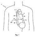
図1は、埋め込まれた心臓ポンプ2を有する患者1を示している。埋め込まれた心臓ポンプ2は、第1のチューブ2aを使って患者の心臓3の左心室3aに接続される。心臓ポンプ2は、第2のチューブ2bを使って患者1の、全般的に4と示されている、大動脈にも接続される。この方法で、手術中、心臓ポンプが、患者の心臓3の血液ポンプ機能を補助するか、または置き換える。 FIG. 1 shows a patient 1 having an implanted
本発明による血栓除去デバイス10は、心臓ポンプ2の第2のチューブ2b、つまり、患者1の大動脈4に至るチューブ内に設けられているように示されている。このことは、第2のチューブ2bによって形成される血流通路の一部が、血栓除去デバイス10内の血流通路によって置き換えられることを意味する。したがって、血栓除去デバイス10は、患者の人工血管内に挿入可能な人工デバイスである。血栓除去デバイスの機能は、第2のチューブ2bによって輸送される血液中の血栓を除去することである。これらの血栓は、好ましくは、患者の体内の空いている場所に移動される。しかし、これらを、代替として、その後の除去または貯蔵のため、血栓除去デバイス10に接続されている袋10aなどの収集容積内に集めることも可能である。袋10aの好ましい貯蔵容量は、例えば、100ミリリットル超であるものとしてよい。血栓除去デバイスは、人工デバイスであるが、患者の血管内に直接挿入されるか、または血管の両端の間に接続されるものとすることが可能である。 The
血栓除去デバイスは、好ましくは、外科手術で、患者の血流通路内に挿入可能であり、患者の腹部または胸部または頭部または頸部または後腹膜または患者の四肢内に留置される。 The thrombectomy device is preferably surgically insertable into the patient's blood flow passage and is placed in the patient's abdomen or chest or head or neck or retroperitoneum or patient limb.
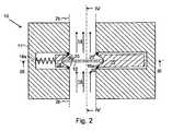
次に、血栓除去デバイス10の第1の好ましい一実施形態の設計について図2〜4を参照しつつ詳しく説明する。図2は、第2のチューブ2bによって形成される血流通路内に血栓除去デバイスが設けられている断面図を示している。フィルタ12は、ハウジング11内に形成された血流通路14を横切る形で設けられ、図の矢印で示されている、血流によって第2のチューブ2b内の前方に送られる潜在的血栓を停止する機能を有する。この好ましい実施形態では、フィルタ12は、生体適合性金属またはプラスチックなどのある種の好適な材料でできている複数の好ましくは等間隔に並ぶストリップ12aを備える。これらのストリップ12aは、好ましくは相互に平行となるように配置される。 The design of the first preferred embodiment of the
2つの隣接するストリップの間の距離は、血栓を停止させるのに十分な小ささである。したがって、この距離は、好ましくは2ミリメートル未満であり、なおいっそう好ましくは1.0ミリメートル未満であるが、目的がより大きな血栓のみから脳を保護することであれば、距離は大きくてもかまわない。好ましい実施形態における血流通路14は、本質的に正方形の断面形状を有するが、矩形や円形などの適当な形状を取りうることは理解されるであろう。 The distance between two adjacent strips is small enough to stop the thrombus. Thus, this distance is preferably less than 2 millimeters and even more preferably less than 1.0 millimeter, although the distance can be larger if the objective is to protect the brain from only larger thrombi. . The
複数のストリップ12aを血流通路14を横切る形でフィルタとして備えることによって、層状血流がフィルタの下流に生じ、これは血栓防止の観点からは有利である。血流の構成は、所望の断面形状の複数のストリップ12aを用意することでさらに高められうるが、図4に示されている矩形の形状は、大半の目的に適したものである。 By providing a plurality of
血流通路14の方向に本質的に垂直な、つまり、血流の方向に本質的に垂直な方向に移動可能な第1のピストン16が備えられる。この第1のピストン16は、圧縮空気、ソレノイド装置、電気サーボ・モータ、または同様のものなどの何らかの好適なアクチュエータ手段によって駆動される。モータを使用することで、非常に高速に放出することが可能な蓄積された力を増大することが可能であるが、そのような力の一例がバネである。好ましい実施形態では、圧縮空気はアクチュエータ手段として働くが、それというのも、ピストンに適した掛け金手段を使ってピストンに掛け金をかけ、空気圧を増加させ、その後、ピストンを解放することによって、ピストンの速度が非常に高速になるからであり、したがって、フィルタのクリーニング時間を短縮することができる。 A
第1のピストン16の外端部分、つまり、血流通路14に面する端部は、血栓除去デバイス10の非活性状態において血流通路の壁と本質的に同一平面上にある。また、外端部分には、凹部分つまり陥凹部16a(図では誇張されている)が設けられ、これが、以下で説明されるように、血栓捕捉手段として働く。 The outer end portion of the
第1のピストン16のぶつかる範囲は、図5〜8を参照しつつ以下で説明されるように、ピストンが血流通路14を横切る形で延在するような範囲である。ストリップ12aの個数に対応する数の収容通路16bが第1のピストン16内に設けられ、第1のピストンが延びた位置にあるときにストリップがこれらの収容通路に収まる。 The range in which the
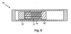
第1のピストン16は、血流通路の方向に複数のスルー・ホール17も備える。図9を参照しつつ以下で説明されるように、クリーニング操作時にも、これらのスルー・ホールにより血流通路内に血液を貫流させることができる。 The
第1のピストン16からの血流通路14を横切る形で第2のピストン18が設けられる。また、この第2のピストン18は、血流通路14の方向に本質的に垂直な方向に移動可能であり、例えば、バネ18aを使ってその方向にバイアスがかけられる。同様に、第2のピストンの外端部分は、第1のピストン16の陥凹部16aに類似の陥凹部18bを備える。 A
第1および第2のピストン16、18は、Oシーリングなどの、各シーリング20を使ってハウジング11に封止される。 The first and
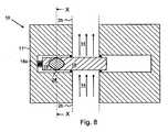
次に、上述のデバイスの異なる操作ステップを示す、図5〜8を参照しつつ、本発明による方法の好ましい一実施形態について説明する。図5は、図2のものと類似している図面である。しかし、この図は、操作時の血栓除去デバイス10を示しており、全般的に22で示した血栓がフィルタ12上に集まっている。 A preferred embodiment of the method according to the present invention will now be described with reference to FIGS. 5-8, showing the different operating steps of the device described above. FIG. 5 is a drawing similar to that of FIG. However, this figure shows the
図6では、第1のピストン16は、図5に示されている引っ込められた開始位置から延びた位置へ直線的に移動しており、その外端部分は、第2のピストン18と接触している。第1のピストン16の外端内に陥凹部16aがあるため、血栓22が陥凹部16a内に集まり、それにより、第1のピストン16の移動時に第1のピストン16と一緒に移動されている。図6に示されているステップで、血栓は、第1のピストン16と第2のピストン18との間の陥凹部16aに封じ込められる。 In FIG. 6, the
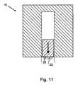
図6に示されている位置からの追加距離だけ第1のピストン16を移動することによって、第2のピストン18が、バネ18aの力に抗して完全に引っ込められた位置まで押される(図7を参照)。複数のストリップ12aが、この位置において、第1のピストン内の各収容通路16b内に完全に受け入れられる。第1および第2のピストンの外端が、血栓を封じ込める遮られていない空洞を画定することがわかる。これにより、好適な手段を使ってこれらの血栓を除去することが可能である。このような手段の1つは、第3のピストン24とすることが可能であり、これは血流通路14の方向と第1および第2のピストン16、18の移動の方向の両方に垂直な方向に移動可能である。この第3のピストンの移動は、圧縮空気、ソレノイド、電気モータなどを使って制御可能であり、この第3のピストンは、第1のピストン16によって集められた血栓を擦り落として、血栓除去デバイス10および血流通路14の外部の場所に血栓を移動させる。 By moving the
図9は、完全に延びた位置にある第1のピストン16の側面図、つまり、図8の図面に対応する図面である。ここで、この位置において、スルー・ホール17は、血流通路14に揃えられ、これにより、フィルタ12のクリーニング時にも血液を血流通路14に貫流させることができることがわかる。 FIG. 9 is a side view of the
図10は、図8のX−X線に沿った断面図を示す。第3のピストン24は、図の矢印で示されている、下方の移動時に血栓22を集めることがわかる。血栓は、第3のピストン24が、図11に示されている下端位置に到達したときに、血栓除去デバイス10から排出される。 FIG. 10 is a sectional view taken along line XX in FIG. It can be seen that the
ここでもまた、図7を参照すると、第1のピストン16および第2のピストン18によって形成される空洞から集められた血栓を排出するために、圧縮空気が使用されうることが理解されるであろう。 Again, referring to FIG. 7, it will be understood that compressed air can be used to expel thrombus collected from the cavity formed by the
次に、全般的に28と示されている、上述のような血栓除去デバイスを備える血栓除去システムについて図12〜25を参照しつつ説明する。 A thrombectomy system comprising a thrombectomy device as described above, generally designated 28, will now be described with reference to FIGS.
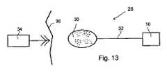
図12のシステムは、患者の腹部に留置された血栓除去デバイス10を備える。 埋め込まれたエネルギー変換デバイス30の形態の内部エネルギー源が、血栓除去デバイス10のエネルギー消費コンポーネントにパワー・サプライ・ライン32を介してエネルギーを供給するように構成されている。外部エネルギー伝送デバイス34は、埋め込まれたエネルギー変換デバイス30に組み込まれた信号受信機によって受信される、無線信号を伝送する無線遠隔制御装置を備える。埋め込まれたエネルギー変換デバイス30は、信号からのエネルギーを電気エネルギーに変換し、これをパワー・サプライ・ライン32を介して供給する。 The system of FIG. 12 comprises a
図12のシステムは、図13より一般化されたブロック図形態で示されており、図13では、垂直線によって全般的に示す患者の皮膚36は、線の右にある患者の内部を線の左にある外部から隔てている。 The system of FIG. 12 is shown in a more generalized block diagram form than in FIG. 13, in which the patient's
図14は、分極エネルギー(polarized energy)によっても操作可能な電気スイッチ38の形態の逆転デバイス(reversing device)が、血栓除去デバイス10を逆転するために患者の体内に埋め込まれている点を除き、図13のものと同じ本発明の一実施形態を示している。外部エネルギー伝送デバイス34の無線遠隔制御装置は、分極エネルギーを伝送する無線信号を送信し、埋め込まれたエネルギー変換デバイス30は、無線分極エネルギーを電気スイッチ38を操作するための分極電流に変換する。電流の極性が、埋め込まれているエネルギー変換デバイス30によって切り換えられた場合、電気スイッチ38は、血栓除去デバイス10によって実行される機能を逆転する。 FIG. 14 shows that a reversing device in the form of an
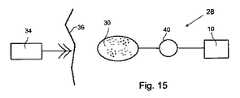
図15は、血栓除去デバイス10を調節するために患者の体内に埋め込まれている操作デバイス40が、埋め込まれたエネルギー変換デバイス30と血栓除去デバイス10との間に備えられている点を除き、図13のものと同じ本発明の一実施形態を示している。この操作デバイスは、電気サーボモータなどのモータ40の形態のものとすることができる。モータ40は、埋め込まれたエネルギー変換デバイス30からエネルギーの供給を受けるが、その際に、外部エネルギー伝送デバイス34の遠隔制御装置が、無線信号を埋め込まれたエネルギー変換デバイス30の受信機に送信する。 FIG. 15 illustrates that an operating
図16は、操作デバイスも備え、モータ/ポンプ・ユニット78を備えるアセンブリ42の形態をとり、流体タンク46が患者の体内に埋め込まれている点を除き、図13のものと同じ本発明の一実施形態を示している。この場合、血栓除去デバイス10は、液圧式で動作する、つまり、モータ/ポンプ・ユニット44によって作動液が流体タンク46から導管48を通り血栓除去デバイス10に送り込まれて血栓除去デバイスが動作し、モータ/ポンプ・ユニット44によって作動液が血栓除去デバイス10から流体タンク46に送られ、血栓除去デバイスが開始位置に戻る。埋め込まれたエネルギー変換デバイス30は、無線エネルギーを電流、例えば、分極電流に変換し、電力サプライ・ライン50を介してモータ/ポンプ・ユニット44に動力を供給する。 FIG. 16 also includes an operating device, takes the form of an
液圧式で動作する血栓除去デバイス10の代わりに、操作デバイスが空気圧式操作デバイスを備えることも企図される。この場合、調節のために圧縮空気が使用可能であり、流体タンクは空気室で置き換えられ、流体は空気で置き換えられる。 Instead of the
図17は、無線遠隔制御装置を伴う外部エネルギー伝送デバイス34、この場合には液圧式で動作する血栓除去デバイス10、および埋め込まれたエネルギー変換デバイス30を備え、また作動液タンク52、モータ/ポンプ・ユニット44、および液圧弁切り換えデバイス54の形態の逆転デバイスをさらに備え、これらはすべて患者の体内に埋め込まれる、本発明の一実施形態を示している。モータ/ポンプ・ユニット44のモータは、電気モータである。外部エネルギー伝送デバイス34の無線遠隔制御装置からの制御信号に対する応答として、埋め込まれたエネルギー変換デバイス30は、制御信号によって搬送されるエネルギーからのエネルギーを動力としてモータ/ポンプ・ユニット44に供給し、これにより、モータ/ポンプ・ユニット44は、作動液を作動液タンク52と血栓除去デバイス10との間に分配する。外部エネルギー伝送デバイス34の遠隔制御装置は、液圧弁切り換えデバイス54を制御して、流体が血栓除去デバイス10を操作するためにモータ/ポンプ・ユニット44によって作動液タンク52から血栓除去デバイス10に送り込まれる一方の方向と流体が血栓除去デバイスを開始位置に戻すためにモータ/ポンプ・ユニット44によって血栓除去デバイス10から作動液タンク52に戻される別の反対方向との間で作動液の流れ方向を切り換える。 FIG. 17 comprises an external
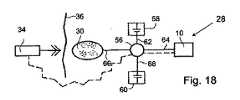
図18は、外部エネルギー伝送デバイス34、アキュムレータ58、およびキャパシタ60の無線遠隔制御装置によって制御される内部制御ユニット56も患者の体内に埋め込まれている点を除き、図13のものと同じ本発明の一実施形態を示している。内部制御ユニット56は、エネルギーを血栓除去デバイス10に供給する、アキュムレータ58内の埋め込まれたエネルギー変換デバイス30から受け取った電気エネルギーの貯蔵を処理する。外部エネルギー伝送デバイス34の無線遠隔制御装置からの制御信号に対する応答として、内部制御ユニット56は、アキュムレータ58から電気エネルギーを放出し、パワー・ライン62および64を介して放出されたエネルギーを変換するか、またはパワー・ライン66、電流を安定化するキャパシタ60、パワー・ライン68、およびパワー・ライン64を介して埋め込まれたエネルギー変換デバイス30からの電気エネルギーを直接変換して、血栓除去デバイス10を操作する。 FIG. 18 shows the same invention as that of FIG. 13 except that an
内部制御ユニットは、好ましくは患者の体外からプログラム可能である。好ましい一実施形態では、事前プログラムされたタイム・スケジュールに従って繰り返し血管系から血栓を除去し、血栓を血管系の外に留置するように血栓除去デバイス10を調節する、内部制御ユニットのプログラミングが行われる。 The internal control unit is preferably programmable from outside the patient's body. In a preferred embodiment, an internal control unit is programmed that repeatedly removes the thrombus from the vasculature according to a preprogrammed time schedule and adjusts the
代替形態によれば、図18の実施形態ではキャパシタ60を省くことができる。他の代替形態によれば、この実施形態ではアキュムレータ58を省くことができる。 According to an alternative, the
図19は、血栓除去デバイス10の操作用にエネルギーを供給するためのバッテリ70および血栓除去デバイス10の動作をスイッチングするための電気スイッチ72も患者の体内に埋め込まれている点を除き、図13のものと同じ本発明の一実施形態を示している。電気スイッチ72は、埋め込まれたエネルギー変換デバイス30によって供給されるエネルギーによって操作され、バッテリ70が使用中でない、オフ・モードから、血栓除去デバイス10の操作のためバッテリ70がエネルギーを供給する、オン・モードに切り換えられる。 FIG. 19 shows that a
図20は、外部エネルギー伝送デバイス34の無線遠隔制御装置によって制御可能な内部制御ユニット56も患者の体内に埋め込まれている点を除き、図19のものと同じ本発明の一実施形態を示している。この場合、電気スイッチ72は、埋め込まれたエネルギー変換デバイス30によって供給されるエネルギーによって操作され、無線遠隔制御装置が内部制御ユニット56を制御することを妨げられている、バッテリが使用中でない、オフ・モードから、遠隔制御装置が内部制御ユニット56を制御して血栓除去デバイス10の操作のためバッテリ70から電気エネルギーを放出することを許される、スタンバイ・モードに切り換えられる。 FIG. 20 shows an embodiment of the invention identical to that of FIG. 19 except that an
図21は、アキュムレータ58がバッテリ70の代わりに使用され、埋め込まれたコンポーネントが異なる仕方で相互接続されている点を除き、図20のものと同じ本発明の一実施形態を示している。この場合、アキュムレータ58は、埋め込まれたエネルギー変換デバイス30からのエネルギーを貯蔵する。外部エネルギー伝送デバイス34の無線遠隔制御装置からの制御信号に対する応答として、内部制御ユニット56は、電気スイッチ72を制御して、アキュムレータ58が使用中でない、オフ・モードから、アキュムレータ58が血栓除去デバイス10の操作のためエネルギーを供給する、オン・モードに切り換える。 FIG. 21 shows an embodiment of the invention that is the same as that of FIG. 20, except that an
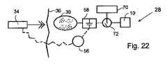
図22は、バッテリ70も患者の体内に埋め込まれ、埋め込まれたコンポーネントが異なる仕方で相互接続されている点を除き、図21のものと同じ本発明の一実施形態を示している。外部エネルギー伝送デバイス34の無線遠隔制御装置からの制御信号に対する応答として、内部制御ユニット56は、電気スイッチ72の操作用にエネルギーを送出するアキュムレータ58を制御して、バッテリ70が使用中でない、オフ・モードから、バッテリ70が血栓除去デバイス10の操作のため電気エネルギーを供給する、オン・モードに切り換える。 FIG. 22 shows an embodiment of the invention that is the same as that of FIG. 21 except that a
あるいは、電気スイッチ72は、アキュムレータ58によって供給されるエネルギーによって操作され、無線遠隔制御装置が電気エネルギーを供給するバッテリ70を制御することを妨げられており、使用中でない、オフ・モードから、無線遠隔制御装置が血栓除去デバイス10の操作のため電気エネルギーを供給するバッテリ70を制御することを許される、スタンバイ・モードに切り換えることができる。 Alternatively, the
図23は、モータ40、ギア・ボックス74の形態の機械式逆転デバイス、およびギア・ボックス74を制御するための内部制御ユニット56も患者の体内に埋め込まれるという点を除き、図19のものと同じ本発明の一実施形態を示している。内部制御ユニット56は、ギア・ボックス74を制御して、血栓除去デバイス10によって実行される機能を逆転する(機械式操作)。 FIG. 23 is the same as that of FIG. 19 except that a
図24は、埋め込まれたコンポーネントが異なる仕方で相互接続されている点を除き、図22のものと同じ本発明の一実施形態を示している。したがって、この場合、内部制御ユニット56は、アキュムレータ58、適宜、キャパシタが電気スイッチ72を作動させてオン・モードに切り換えるときにバッテリ70から電力を供給される。電気スイッチ72が、オン・モードにある場合、内部制御ユニット56は、血栓除去デバイス10の操作のためにエネルギーを供給するよう、または供給しないようバッテリ70を制御することが許される。 FIG. 24 shows an embodiment of the invention that is the same as that of FIG. 22 except that the embedded components are interconnected differently. Thus, in this case, the
図25は、さまざまな通信オプションを実現するための装置の埋め込まれたコンポーネントの企図されうる組み合わせの概略を示している。基本的に、血栓除去デバイス10、内部制御ユニット56、モータ/ポンプ・ユニット44、および外部無線遠隔制御装置を含む外部エネルギー伝送デバイス34がある。上ですでに説明されているように、無線遠隔制御装置は制御信号を送信し、内部制御ユニット56はこの信号を受信して、装置のさまざまな埋め込まれたコンポーネントを制御する。 FIG. 25 outlines a possible combination of embedded components of a device for implementing various communication options. Basically, there is an external
血管内の圧力などの、患者の身体パラメータを感知するために、フィードバック・デバイス、好ましくはセンサ76の形態のものを患者の体内に埋め込むことができる。内部制御ユニット56、あるいは外部エネルギー伝送デバイス34の外部無線遠隔制御装置は、センサ76からの信号に対する応答として血栓除去デバイス10を制御することができる。トランシーバをセンサ76と組み合わせることで、感知された身体パラメータに関する情報を外部無線遠隔制御装置に送信することができる。無線遠隔制御装置は、信号送信機またはトランシーバを備えることができ、内部制御ユニット56は、信号受信機またはトランシーバを備えることができる。あるいは、無線遠隔制御装置は、信号受信機またはトランシーバを備えることができ、内部制御ユニット56は、信号送信機またはトランシーバを備えることができる。上記のトランシーバ、送信機、および受信機は、患者の体内から患者の体外へ血栓除去デバイス10に関係する情報またはデータを送信するために使用されうる。 A feedback device, preferably in the form of a
あるいは、血栓除去デバイス10の機能パラメータを感知するように、センサ76を配置することもできる。 Alternatively, the
モータ/ポンプ・ユニット44およびモータ/ポンプ・ユニット44に電力を供給するためのバッテリ70が、埋め込まれる場合、バッテリ70は、バッテリ70の状態に関する情報を送信するためのトランシーバを装備することができる。 If the motor /
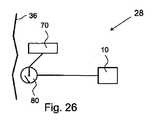
図26は、血栓除去デバイス10が、患者の体外から調節される代替実施形態を示している。血栓除去システム28は、皮下スイッチ80を介してバッテリ70に接続された血栓除去デバイス10を備える。したがって、血栓除去デバイス10の調節は、皮下スイッチを手で圧すことによって非侵襲的に実行され、これにより、血栓除去デバイス10の操作がオン、オフされる。示されている実施形態は、簡素化したものであること、および内部制御ユニットなどの追加のコンポーネントを血栓除去システムに追加することができることは理解されるであろう。 FIG. 26 illustrates an alternative embodiment in which the
図27は、血栓除去システム28が、作動液タンク52と流体で連通する血栓除去デバイス10を備える代替実施形態を示している。非侵襲的調節は、血栓除去デバイス10に接続された液圧タンクを手で圧すことによって実行される。 FIG. 27 illustrates an alternative embodiment in which the
本発明によるシステムの他の実施形態は、患者の体内から患者の体外に情報を送信し、血栓除去デバイスもしくはシステムの少なくとも1つの機能パラメータまたは患者の身体パラメータに関係するフィードバック情報を供給し、これによりシステムの性能を最適化するためのフィードバック・デバイスを備える。 Another embodiment of the system according to the invention transmits information from inside the patient to outside the patient and provides feedback information relating to at least one functional parameter of the thrombectomy device or system or patient physical parameters, Provides a feedback device to optimize system performance.
デバイスの1つの好ましい機能パラメータは、内部エネルギー源をチャージするためのエネルギー伝達と相関するものである。 One preferred functional parameter of the device is one that correlates with energy transfer to charge the internal energy source.
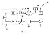
図28には、正確な量のエネルギーを、皮膚36が垂直線で示されている、患者の体内に埋め込まれている血栓除去システム28に供給するための配置構成の概略が示されている。血栓除去デバイス10は、患者の体内に同様に配置される、好ましくは患者の皮膚36の真下に配置される、埋め込まれたエネルギー変換デバイス30に接続される。一般的に言って、埋め込まれたエネルギー変換デバイス30は、腹部内、胸腔内、筋膜内(例えば、腹壁内)、皮下、または他の好適な場所に留置することができる。埋め込まれたエネルギー変換デバイス30は、埋め込まれたエネルギー変換デバイス30の付近の患者の皮膚36の外側に配置されている外部エネルギー伝送デバイス34内に備えられている外部エネルギー源34aから伝送される無線エネルギーEを受け取るように構成されている。 FIG. 28 shows a schematic of an arrangement for delivering an accurate amount of energy to a
当技術分野でよく知られているように、無線エネルギーEは、一般的に、外部エネルギー源34a内に配置された一次コイルおよび埋め込まれたエネルギー変換デバイス30内に配置された隣接する二次コイルを備えるデバイスなどの、好適な経皮エネルギー伝達(TET)デバイスを使って伝達されうる。電流が一次コイルに送り込まれると、例えば、バッテリもしくはキャパシタなどのエネルギー貯蔵デバイスもしくはアキュムレータ内に入ってくるエネルギーを貯蔵した後、エネルギーが電圧の形態で、血栓除去デバイスを操作するために使用されうる二次コイル内に誘導される。しかし、本発明は、一般的に、特定のエネルギー伝達技術に限定されず、TETデバイスもしくはエネルギー貯蔵デバイス、および任意の種類の無線エネルギーが使用されうる。 As is well known in the art, the wireless energy E is typically a primary coil disposed within the
伝達されたエネルギーの量は、上述のように、決定されたエネルギー収支に基づいて外部エネルギー源34aを制御する外部制御ユニット34bを使って調節されうる。適正量のエネルギーを伝達するために、血栓除去デバイス10に接続されている内部制御ユニット56を使ってエネルギー収支および必要なエネルギー量を決定することができる。したがって、内部制御ユニット56は、血栓除去デバイス10のいくつかの特性を測定する、ともかくも、血栓除去デバイス10の適切な操作に要求されるエネルギーの必要量を反映する、図示されていない、好適なセンサまたは同様のものによって得られるさまざまな測定結果を受け取るように構成されうる。さらに、患者の現在状態も、好適な測定デバイスまたはセンサを使って検知することができ、これにより、患者の症状を反映するパラメータが得られる。したがって、そのような特性および/またはパラメータは、消費電力、運転モード、および温度などの、血栓除去デバイス10の現在状態、さらには例えば、体温、血圧、心拍、および呼吸によって反映される患者の容体に関係するものとすることができる。 The amount of energy transferred can be adjusted using an
さらに、エネルギー貯蔵デバイスまたはアキュムレータ58は、受け取ったエネルギーを蓄積しておき血栓除去デバイス10において後から使用するために、埋め込まれたエネルギー変換デバイス30に適宜接続することができる。代替として、またはそれに加えて、必要なエネルギー量を反映する、そのようなアキュムレータの特性も同様に測定することができる。アキュムレータは、バッテリで置き換えることができ、測定された特性は、電圧、温度などのバッテリの現在状態に関係するものとすることができる。十分な電圧および電流を血栓除去デバイス10に供給するために、また過熱を避けるためにも、バッテリは、埋め込まれたエネルギー変換デバイス30から適正量のエネルギーを受け取ることによって最適なチャージをされるべきである、つまり、チャージ量は少なすぎたり多すぎたりしてはならないということははっきりと理解される。アキュムレータは、対応する特性を持つキャパシタであってもよい。 Furthermore, the energy storage device or
例えば、バッテリ特性を定期的に測定して、バッテリの現在状態を調べ、そしてその結果を内部制御ユニット56内の適切な貯蔵手段に状態情報として格納するとよい。したがって、新しい測定が行われた場合には、必ず、それに応じて格納されているバッテリ状態情報を更新することができる。このようにして、バッテリの状態は、適正量のエネルギーを伝達することによって「較正する」ことができ、それにより、バッテリを最適な状態に保つ。 For example, the battery characteristics may be measured periodically to determine the current state of the battery, and the results stored in the appropriate storage means within the
こうして、内部制御ユニット56は、血栓除去デバイス10上の上述のセンサまたは測定デバイス、または患者、または使用されている場合にはエネルギー貯蔵デバイス、またはこれらの任意の組み合わせによってなされた測定結果に基づいてエネルギー収支および/または現在必要とされているエネルギー量(単位時間当たりのエネルギーまたは蓄積されたエネルギー)を決定するように構成される。内部制御ユニット56は、内部信号送信機82にさらに接続され、決定された必要エネルギー量を反映する制御信号を、外部制御ユニット34bに接続されている外部信号受信機34cに送信するように構成されている。次いで、外部エネルギー源34aから伝送されるエネルギーの量が、受信された制御信号に対する応答として調節されうる。 Thus, the
あるいは、センサ測定結果を外部制御ユニット34bに直接送信することができ、その場合、エネルギー収支および/または現在必要とされているエネルギー量は、外部制御ユニット34bによって決定することができ、したがって、内部制御ユニット56の上述の機能が外部制御ユニット34b内に統合されている。その場合、内部制御ユニット56は、省くことができ、センサ測定結果は、測定結果を外部信号受信機34cおよび外部制御ユニット34bに送信する内部信号送信機82に直接供給される。次いで、エネルギー収支および現在必要とされているエネルギー量が、これらのセンサ測定結果に基づいて外部制御ユニット34bによって決定されうる。 Alternatively, the sensor measurement results can be sent directly to the
したがって、本発明の解決策では、例えば、エネルギー量、エネルギー差、または血栓除去デバイス10によって使用されるエネルギー比率と比較したエネルギー受け取り率に関して、受け取ったエネルギーと比較したエネルギーの実際の使用に基づいているため以前の解決策に比べて効率がよい、必要なエネルギーを示す情報のフィードバックを採用している。血栓除去デバイスは、受け取ったエネルギーを消費に使用するか、またはエネルギー貯蔵デバイスまたは同様のものへのエネルギーの貯蔵に使用することができる。したがって、上述の異なるパラメータは、関連する場合、また必要な場合に使用され、次いで、実際のエネルギー収支を決定するための手段として使用される。 しかし、このようなパラメータは、血栓除去デバイスを特に操作するために内部的に実行されるアクションに対し本質的に必要になることもある。 Thus, the solution of the present invention is based on the actual use of energy compared to the received energy, for example with respect to the amount of energy, energy difference, or energy reception rate compared to the energy ratio used by the
内部信号送信機82および外部信号受信機34cは、ラジオ信号、IR(赤外線)信号、または超音波信号などの好適な信号伝達手段を使用して独立したユニットとして実装されうる。あるいは、内部信号送信機82および外部信号受信機34cは、基本的に同じ伝送技術を使用して、エネルギー伝達に関して逆方向に制御信号を伝達するために、それぞれ、埋め込まれたエネルギー変換デバイス30および外部エネルギー源34a内に一体化することができる。制御信号は、周波数、位相、または振幅に関して変調されうる。 The
結論を言うと、図28に示されているエネルギー供給配置構成は、基本的に以下のようにして動作しうる。エネルギー収支が、まず最初に、内部制御ユニット56によって決定される。必要エネルギー量を反映する制御信号も、内部制御ユニット56によって生成され、制御信号は、内部信号送信機82から外部信号受信機34cに送信される。あるいは、エネルギー収支は、上述のように、その代わりに実装に応じて外部制御ユニット34bによって決定されうる。その場合、制御信号は、さまざまなセンサから測定結果を搬送することができる。次いで、外部エネルギー源34aから放射されるエネルギーの量が、例えば、受信された制御信号に対する応答として、決定されたエネルギー収支に基づいて、外部制御ユニット34bによって調節されうる。このプロセスは、エネルギー伝達の進行中に特定の間隔で間歇的に繰り返されうるか、またはエネルギー伝達中に多少連続的に実行されうる。 In conclusion, the energy supply arrangement shown in FIG. 28 can basically operate as follows. The energy balance is first determined by the
伝達されるエネルギーの量は、一般的には、電圧、電流、振幅、波の周波数、およびパルス特性などの外部エネルギー源34aにおけるさまざまな伝送パラメータを調整することによって調節することができる。 The amount of energy transferred can generally be adjusted by adjusting various transmission parameters in the
そこで、患者の体内に埋め込まれた電気的に操作可能な血栓除去デバイスに供給される無線エネルギーの伝送を制御するための方法が提供される。無線エネルギーEは、患者の体外に配置されている外部エネルギー源から伝送され、これを患者の体内に配置されている内部エネルギー受信機が受け取るが、外部エネルギー受信機は受け取ったエネルギーを直接的または間接的に供給するために血栓除去デバイスに接続されている。内部エネルギー受信機が受け取ったエネルギーと血栓除去デバイスによって使用されるエネルギーとの間のエネルギー収支が決定される。次いで、外部エネルギー源からの無線エネルギーEの伝送が、決定されたエネルギー収支に基づいて制御される。 Thus, a method is provided for controlling the transmission of wireless energy supplied to an electrically operable thrombectomy device implanted in a patient's body. Wireless energy E is transmitted from an external energy source located outside the patient's body, which is received by an internal energy receiver located inside the patient's body, where the external energy receiver directly or directly receives the received energy. Connected to a clot removal device for indirect delivery. An energy balance is determined between the energy received by the internal energy receiver and the energy used by the thrombectomy device. The transmission of wireless energy E from the external energy source is then controlled based on the determined energy balance.
患者の体内に埋め込まれた電気的に操作可能な血栓除去デバイスに供給される無線エネルギーの伝送を制御するためのシステムも実現される。システムは、患者の体外に配置されている外部エネルギー源から、患者の体内に配置されている埋め込まれたエネルギー変換デバイスが受け取る無線エネルギーEを伝送するように構成され、埋め込まれたエネルギー変換デバイスは受け取ったエネルギーを直接的または間接的に供給するために血栓除去デバイスに接続されている。システムは、埋め込まれたエネルギー変換デバイスが受け取るエネルギーと血栓除去デバイスに使用されるエネルギーとの間のエネルギー収支を決定し、決定されたエネルギー収支に基づいて、外部エネルギー源からの無線エネルギーEの伝送を制御するようにさらに構成される。 A system for controlling the transmission of wireless energy supplied to an electrically operable thrombectomy device implanted in a patient's body is also realized. The system is configured to transmit wireless energy E received by an implanted energy conversion device disposed within the patient's body from an external energy source disposed outside the patient's body, wherein the implanted energy conversion device is Connected to the thrombectomy device to directly or indirectly supply the received energy. The system determines an energy balance between the energy received by the implanted energy conversion device and the energy used by the thrombectomy device, and the transmission of wireless energy E from an external energy source based on the determined energy balance Is further configured to control.
デバイスの機能パラメータは、内部エネルギー源をチャージするためのエネルギー伝達と相関する。 The device functional parameters correlate with the energy transfer to charge the internal energy source.
さらに他の代替実施形態では、外部エネルギー源は、患者の体外から制御され、電磁無線エネルギーを放出し、放出される電磁無線エネルギーは、血栓除去デバイスの操作に使用される。 In yet another alternative embodiment, the external energy source is controlled from outside the patient's body and emits electromagnetic wireless energy that is used to operate the thrombectomy device.
他の実施形態では、外部エネルギー源は、患者の体外から制御され、非磁気無線エネルギーを放出し、放出される非磁気無線エネルギーは、血栓除去デバイスの操作に使用される。 In other embodiments, the external energy source is controlled from outside the patient's body and emits non-magnetic wireless energy that is used to operate the thrombectomy device.
当業者であれば、図13〜29による上記のさまざまな実施形態は多くのさまざまな方法で組み合わせることが可能であることに気づくであろう。例えば、分極エネルギーで操作される電気スイッチ38は、図15、18〜24の実施形態のいずれにも組み込むことが可能であり、液圧弁切り換えデバイス54は、図16の実施形態に組み込むことが可能であり、ギア・ボックス74は、図15の実施形態に組み込むことが可能である。 One skilled in the art will realize that the various embodiments described above according to FIGS. 13-29 can be combined in many different ways. For example, an
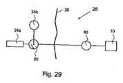
非侵襲的手術を可能にする、血栓除去デバイスを操作するための無線エネルギー伝達を説明してきた。血栓除去デバイスは、無線束縛エネルギーでも操作できることは理解されるであろう。このような一例が図29に示されているが、外部スイッチ84は、パワー・ライン86および88を使って、外部エネルギー源34aと、血栓除去デバイス10を調節する電気モータなどの操作デバイスとの間に相互接続されている。外部制御ユニット34bは、外部スイッチの動作を制御し血栓除去デバイス10の適切な操作を行う。 Wireless energy transfer has been described for operating a thrombectomy device that allows non-invasive surgery. It will be appreciated that the thrombectomy device can also be operated with wireless binding energy. One such example is shown in FIG. 29, where external switch 84 uses power lines 86 and 88 to connect
次に、上述の血栓除去デバイスおよびシステムに関係する方法について詳しく説明する。 Next, methods related to the above-described thrombectomy device and system are described in detail.
腹腔鏡検査腹部アプローチを介して、血栓除去デバイスを患者の体内に外科的に留置することができる。最初に、チューブを患者身体の腹部内に挿入し、このチューブを使用して患者の腹部にガスを充填し、それにより、患者の腹腔を拡大する。次いで、少なくとも2つの腹腔鏡検査トロカールを患者の体内に留置し、その後、カメラをトロカールの1つに通して患者の腹部内に挿入する。少なくとも1つの切開具をトロカールに通して挿入し、患者の2つの意図された領域で切開を実行する。血栓除去デバイスを腹部内の血管系の一部の中に留置する。 A thrombectomy device can be surgically placed in the patient's body via a laparoscopic abdominal approach. First, a tube is inserted into the abdomen of the patient's body and the tube is used to fill the patient's abdomen with gas, thereby enlarging the patient's abdominal cavity. At least two laparoscopic trocars are then placed in the patient's body, after which a camera is inserted through one of the trocars and into the patient's abdomen. At least one incision tool is inserted through the trocar and an incision is performed at the two intended areas of the patient. A thrombectomy device is placed in a portion of the vasculature in the abdomen.
あるいは、血栓除去デバイスは、患者の胸部内に留置されうる。そこで、チューブを患者身体の胸部内に挿入し、このチューブを使用して患者の胸部にガスを充填し、それにより、患者の胸腔を拡大する。次いで、少なくとも2つの腹腔鏡検査トロカールを患者の体内に留置し、その後、カメラをトロカールの1つに通して患者の胸部内に挿入する。少なくとも1つの切開具をトロカールに通して挿入し、患者の2つの意図された領域で切開を実行する。血栓除去デバイスを胸部内の血管系の一部の中に留置する。 Alternatively, the thrombectomy device can be placed in the patient's chest. Therefore, the tube is inserted into the chest of the patient body and the tube is used to fill the patient's chest with gas, thereby enlarging the patient's chest cavity. At least two laparoscopic trocars are then placed in the patient's body, after which a camera is inserted through one of the trocars and into the patient's chest. At least one incision tool is inserted through the trocar and an incision is performed at the two intended areas of the patient. A thrombectomy device is placed in a portion of the vasculature in the chest.
血栓除去デバイスを外科的に留置するための手術方法は、患者の皮膚を切り、患者の腹部または胸部または後腹膜または皮下または四肢内の血管系内の血栓除去デバイスを留置すべき留置領域を切開することから始まる。適当な場所が見つかったら、血栓除去デバイスを留置領域内に留置する。次いで、患者の皮膚を貫通することなくエネルギー源からのエネルギーを使用して血栓除去デバイスに動力を供給しつつ、手術後に、また非侵襲的に、患者の皮膚を貫通することなく血管系から血栓を除去して患者の体外に移すために血栓除去デバイスを使用できる。 Surgical methods for surgically placing a thrombectomy device include cutting the patient's skin and incising the placement region where the thrombectomy device in the patient's abdomen or chest or retroperitoneum or subcutaneous or limb vascular system should be placed. To start with. When a suitable location is found, a thrombectomy device is placed in the placement area. The thrombus is then removed from the vasculature after surgery and non-invasively, without penetrating the patient's skin, while powering the thrombectomy device using energy from the energy source without penetrating the patient's skin. A thrombectomy device can be used to remove and transfer it outside the patient's body.
患者の腹部内の血管系内に血栓除去デバイスを必要とする患者を外科治療するための方法は、好ましくは、患者の腹壁を切って開口部を作り、次いで、血管系の一領域を切開することを含む。血管除去デバイスを血管系内に留置し、腹壁を縫合する。一実施形態では、血栓は、血栓除去デバイスを使って、血管系から患者の腹部内の封入され閉じられた袋内に移される。他の実施形態では、血栓は、空いている腹部に移動される。 A method for surgical treatment of a patient in need of a thrombectomy device within the vasculature in the patient's abdomen preferably cuts the patient's abdominal wall to create an opening and then incises a region of the vasculature Including that. A blood vessel removal device is placed in the vasculature and the abdominal wall is sutured. In one embodiment, the thrombus is transferred from the vasculature into an enclosed and closed bag in the patient's abdomen using a thrombectomy device. In other embodiments, the thrombus is moved to an empty abdomen.
あるいは、患者の胸部内の血管系内に血栓除去デバイスを必要とする患者を外科治療するための方法は、胸壁を切って開口部を作り、次いで、血管系の一領域を切開することを含む。血管除去デバイスを血管系内に留置し、胸壁を縫合する。血管系から血栓を移し去るステップは、胸部内の空いている場所、腹部内の空いている場所、または胸部内の閉じられた袋の中に封入されている場所のいずれかに血栓を移動することを含むことができる。 Alternatively, a method for surgical treatment of a patient in need of a thrombectomy device within the vasculature within the patient's chest includes cutting the chest wall to create an opening and then dissecting a region of the vasculature. . A vessel removal device is placed in the vasculature and the chest wall is sutured. The step of removing the thrombus from the vasculature moves the thrombus to either a vacant place in the chest, a vacant place in the abdomen, or a place enclosed in a closed bag in the chest Can be included.
一実施形態では、血栓を除去するためのシステムを使用する方法は、埋め込まれたエネルギー変換デバイス30およびアキュムレータ58などの埋め込み可能なエネルギー源を患者の体内に埋め込むことを含む。外部エネルギー伝送デバイス34などの外部エネルギー源が、エネルギーをシステムに供給するために備えられる。外部エネルギー源は、無線エネルギーを放射する動作をし、これにより、埋め込み可能なエネルギー源に無線エネルギーを非侵襲的にチャージし、その一方で、患者の体外から埋め込み可能なエネルギー源を制御する。血栓除去デバイスの操作に関連して、エネルギーが放出される。無線エネルギーは、好ましくは、埋め込み可能なエネルギー源に貯蔵される。 In one embodiment, a method of using a system for removing a thrombus includes implanting an implantable energy source, such as an implanted
操作時に、血栓を除去するためのシステムは、手術後に、また非侵襲的に、血栓除去デバイスを調節する。患者の身体の血管系内に蓄積されている血栓を血管系から移し去り、次いで、血管系の外に留置する。これは、好ましくは事前プログラムされたタイム・スケジュールに従って繰り返し、エネルギー源によって行われうる。血管系から血栓を移動し、血栓を血管系の外部に留置することは、好ましくは繰り返され、患者の身体パラメータまたはデバイスの機能パラメータを感知するセンサから入力を得た内部制御ユニットによって少なくとも部分的に制御される。 In operation, the system for removing the thrombus adjusts the thrombectomy device after surgery and non-invasively. Thrombus accumulated in the vasculature of the patient's body is removed from the vasculature and then placed outside the vasculature. This can be done by the energy source, preferably repeating according to a pre-programmed time schedule. Moving the thrombus from the vasculature and placing the thrombus outside the vasculature is preferably repeated, at least in part by an internal control unit that receives input from a sensor that senses the patient's physical parameters or device functional parameters. Controlled.
血栓除去デバイス、血栓除去デバイスを備えるシステム、および本発明による方法の好ましい実施形態を説明した。当業者であれば、これらは添付の特許請求の範囲の範囲内で変えることが可能であることに気づく。 A preferred embodiment of a thrombectomy device, a system comprising a thrombectomy device, and a method according to the invention has been described. Those skilled in the art will recognize that these can be varied within the scope of the appended claims.
血栓除去デバイスは、患者の人工血管内に挿入可能な人工デバイスとして説明された。あるいは、血栓除去デバイスは、患者の血管の2つの開口端の間に留置されるか、または外科手術により血管内に留置されるか、もしくは取り付けられるように構成された人工デバイスである。 The thrombectomy device has been described as an artificial device that can be inserted into a patient's artificial blood vessel. Alternatively, the thrombectomy device is an artificial device configured to be placed between two open ends of a patient's blood vessel, or placed or attached into a blood vessel by surgery.
血栓除去デバイスは、患者の腹部または胸部内に留置されるものとして説明された。これは、患者の腹膜後腔部または頭部または頸部または四肢内に留置されるようにも構成されうる。血栓除去デバイス内のフィルタは、交換可能であり、汚れたら全く新品のフィルタで置き換えられうる。このような解決手段の一実施形態は、図30および31を参照しつつ以下で説明される。 The thrombectomy device has been described as being placed in the patient's abdomen or chest. It can also be configured to be placed in the patient's retroperitoneal cavity or head or neck or limb. The filter in the thrombectomy device is replaceable and can be replaced with a completely new filter if it becomes dirty. One embodiment of such a solution is described below with reference to FIGS.
図30aには、フィルタを保持するためのカセットが示されている。カセット27は、それぞれがフィルタを保持するセグメント130を有する回転シリンダ129を備える。シリンダ129は、シリンダ129を適所に保持して密封する2つの支持材131の間で密封される。好ましくは、接触表面は、許容誤差が小さくなるように表面を封止するためにセラミックスで作られる。埋め込み可能な血栓除去デバイスの血流通路は、カセット127を通過する。カセットは、モータ133によって駆動され、シリンダ129を適切な回数だけ回転させる。好ましくは、フィルタは、新しいフィルタと交換するためにフィルタが血流通路から出るときに、集められた血栓を回転するフィルタと一緒に血流通路から追い出すように設計される。フィルタは、集められた血栓またはフィルタそれ自体に付着している血栓のための空間を好ましくは有するフィルタであればどのような種類のものでもよい。回転するときの両方の封止板へのこのような空間は、好ましくは、血流通路内に見られるフィルタの前ではより大きいものであるべきである。モータは、電源123bによって電力を供給される。電源は、電源123または123aのような電源とすることができる。一実施形態によれば、電源123、123a、および123bは、全く同じ電源である。電源123および123aの場合と同様に、電源123bは、限定はしないが、誘導エネルギー、超音波エネルギー、光エネルギー、または上で述べた他の形態の無線エネルギーを含む、好適な形態の無線エネルギーを受け取ることができる。エネルギーは、カセット127が埋め込まれている患者の皮膚5を通してエネルギーを伝送するように構成された外部無線エネルギー伝送装置6によって供給される。電源132bは、回転するカセット127を制御するために上述のような制御ユニットを備えることもできる。制御ユニットは、ポンプの制御と連携して使用される制御ユニットと類似の方法で、フィードバックを外部に供給し、入力データを外部トランシーバ7から受け取ることができる。 FIG. 30a shows a cassette for holding the filter. The cassette 27 comprises a
図30bには、カセット127が支持材131のある側から示されており、また相隔てて並ぶ回転するシリンダが分解図に示されている。 In FIG. 30b, the
図31aには、カセット127の代替実施形態が示されている。図30aの図面は、図31aの図面に類似している。図31aの実施形態では、多数のシリンダ129が中に収められているマガジン135が備えられる。これにより、マガジン135内のシリンダをシフトすることによってシリンダ129を置き換えることができる。一実施形態では、シリンダは、圧縮空気またはモータによってシフトされる。次いで、フィルタが、最初に、血流通路内で置き換えられ、その後、血流通路の外部の位置において、カセット内で置き換えられる。このような置き換えは、好ましくは、多数のフィルタを135と印されているカセットの一方の側のシリンダ135内に置き、汚れたフィルタをカセットから外へ出しカセットの他方の側のシリンダに移すことによって実施されうる。 In FIG. 31a, an alternative embodiment of
代替実施形態では、代わりに、シリンダ135は、血流通路の外の位置でフィルタをクリーニングするように構成されたクリーニング・デバイスである。 In an alternative embodiment, the
図31bには、カセット127が支持材131のある側から示されており、また相隔てて並ぶ回転するシリンダが分解図に示されている。 In FIG. 31b, the
本明細書で説明されている任意の実施形態または実施形態の一部または機能または方法または関連するシステムまたはシステムの一部は、任意の組み合わせで組み合わせることができることに留意されたい。 It should be noted that any embodiment or part of an embodiment or function or method or related system or part of a system described herein may be combined in any combination.
1 患者; 2 心臓ポンプ; 2a 第1のチューブ; 2b 第2のチューブ;
3 心臓; 3a 左心室; 4 大動脈; 10 血栓除去デバイス;
10a 収集容積。1 patient; 2 heart pump; 2a first tube; 2b second tube;
3 heart; 3a left ventricle; 4 aorta; 10 thrombectomy device;
10a Collection volume.
Claims (116)
Translated fromJapanese血流通路を通じて患者の血液を循環させることができるように患者の血管系に接続される血流通路と、
血流通路を貫流する血液中に生じた血栓を集める、血流通路内に設けられたフィルタと、
血流通路からフィルタによって集められた血栓を移動させるクリーニング・デバイスと
を備える血栓除去デバイス。A thrombectomy device that removes a thrombus from a patient's vasculature and is implantable in the patient's body;
A blood flow passage connected to the patient's vasculature so that the patient's blood can circulate through the blood flow passage;
A filter provided in the blood flow passage for collecting blood clots generated in the blood flowing through the blood flow passage;
A thrombectomy device comprising: a cleaning device that moves thrombus collected by the filter from the blood flow passage.
ことを特徴とする、請求項1に記載の血栓除去デバイス。Comprising at least one new filter, wherein the cleaning device is configured to replace the new filter with the collected thrombus in the blood flow passage.
The thrombectomy device according to claim 1, wherein
ことを特徴とする、請求項1または2に記載の血栓除去デバイス。The cleaning device is configured to move the thrombus to a vacant location in the patient's body;
The thrombectomy device according to claim 1 or 2, characterized in that
そして、非侵襲的に調整のステップは、前記電波式遠隔操作を使用して実行される、請求項62に記載の方法。The system includes radio remote control,
63. The method of claim 62, wherein a non-invasive adjustment step is performed using the radio remote control.
埋め込み可能なエネルギー源を患者に埋め込み、
外部のエネルギー源を準備し、
前記外部のエネルギー源を無線エネルギーを放出するよう制御し、
埋め込み可能なエネルギー源を前記無線エネルギーで非侵襲的にチャージし、
患者の外側から埋め込み可能なエネルギー源を制御し、
血栓除去デバイスの操作に関して用いるエネルギーを放出する、
ことを特徴とする方法。A method of using the thrombus removal system of claim 33, comprising:
Implant an implantable energy source in the patient,
Prepare an external energy source,
Controlling the external energy source to emit wireless energy;
Non-invasively charging an implantable energy source with the wireless energy;
Control the implantable energy source from outside the patient,
Release energy used for the operation of the clot removal device,
A method characterized by that.
患者の外側で外部のエネルギー源を準備し、
血栓除去デバイスを操作するために操作デバイスを準備し、
患者の体外で外部エネルギー源を、無線エネルギーを放出させるために制御し、の
前記操作デバイスの操作のために前記した放出された無線エネルギーを使用する、
ことを特徴とする方法。A method of using the thrombus removal system of claim 33, comprising:
Prepare an external energy source outside the patient,
Prepare an operating device to operate the clot removal device,
Controlling an external energy source outside the patient's body to emit wireless energy and using the emitted wireless energy as described above for operation of the operating device;
A method characterized by that.
ことを特徴とする、請求項76に記載の方法。Converting wireless energy into electrical energy within the patient using an implanted energy conversion device, wherein electrical energy is used during operation of the thrombectomy device;
77. The method of claim 76, wherein:
血栓除去装置を操作するために、放出された非磁性無線エネルギーを、直接的または間接的に使用する、ことを特徴とする請求項76に記載の方法。Control external energy sources for the emission of electromagnetic radio energy outside the patient,
77. The method of claim 76, wherein the released non-magnetic wireless energy is used directly or indirectly to operate the thrombectomy device.
患者体内の血管係に累積された血栓を、血栓除去デバイスで血管系から間隔をあけるよう移動させ、
血栓を血管系の外側に位置させる、
ことを特徴とする方法。A method for non-invasively controlling a thrombus removal system according to claim 33 after surgery,
The thrombus accumulated in the blood vessels in the patient is moved away from the vasculature with a thrombectomy device,
Positioning the thrombus outside the vasculature,
A method characterized by that.
ことを特徴とする請求項81に記載の方法。The steps of moving the thrombus away from the vasculature and positioning the thrombus outside the vasculature are repeated and received by an internal control unit that receives input from a sensor that detects a physical parameter of the patient or a functional parameter of the device. At least partly controlled,
82. The method of claim 81, wherein:
針または管のような器具を患者の腹部に嵌入し、
針または管のような器具を使用して、患者の腹部をガスで満たして拡張させ、
少なくとも2つの腹腔鏡検査外套針を配置し、
腹腔鏡検査外套針のうちの一方によってカメラを患者の腹部に嵌入し、
前記少なくとも2つの腹腔鏡検査外套針の1つよって少なくとも一つのツールを嵌入し、患者の意図した配置領域を解剖し、
腹部の血管系の一部に血栓除去デバイスを配置し、
有効に血管系ポストから血栓を間隔をあけて移動させ、
エネルギー源でデバイスを駆動する
ことを特徴とする方法。Surgical placement of a thrombectomy device by laparoscopic methods,
Insert a device such as a needle or tube into the patient's abdomen,
Using an instrument such as a needle or tube to fill and expand the patient's abdomen with gas,
Place at least two laparoscopic trocars,
Insert the camera into the patient's abdomen with one of the laparoscopic trocars,
Inserting at least one tool by one of the at least two laparoscopic trocars, dissecting the intended placement area of the patient,
Place a thrombectomy device on part of the abdominal vasculature,
Effectively move the thrombus from the vascular post at intervals,
A method comprising driving a device with an energy source.
針または管のような器具を患者の胸部に嵌入し、
針または管のような器具を使用して、患者の胸部の空腔をガスで満たして拡張させ、
少なくとも2つの腹腔鏡検査外套針を配置し、
腹腔鏡検査外套針のうちの一方によってカメラを患者の胸部に嵌入し、
前記少なくとも2つの腹腔鏡検査外套針の1つよって少なくとも一つのツールを嵌入し、患者の意図した配置領域を解剖し、
胸部の血管系の一部に血栓除去デバイスを配置し、
有効に血管系ポストから血栓を間隔をあけて移動させ、
エネルギー源でデバイスを駆動する
ことを特徴とする方法。A method of surgically placing a thrombectomy device on a patient's chest by a laparoscopy method,
Insert a device such as a needle or tube into the patient's chest,
Using an instrument such as a needle or tube, the patient's chest cavity is filled with gas and expanded,
Place at least two laparoscopic trocars,
Insert the camera into the patient's chest with one of the laparoscopic trocars,
Inserting at least one tool by one of the at least two laparoscopic trocars, dissecting the intended placement area of the patient,
Place a thrombectomy device on part of the vasculature of the chest,
Effectively move the thrombus from the vascular post at intervals,
A method comprising driving a device with an energy source.
場所に所で配置領域を解剖する、腹部または胸部の血管系または腹膜後頭部の領域内でまたは、皮下に、血栓除去デバイスを配置すること、
手術後、非侵襲的に、患者の皮膚(血管系からその外側へのいかなる血栓も)を透過せずに、血栓除去デバイスを駆動するために患者の皮膚によるいかなる攻略のないもエネルギー源からエネルギーを使用する外科的に患者の血栓除去デバイスを配置するための方法。Cutting the patient's skin,
Dissect the placement area in place, place the thrombectomy device in the abdominal or thoracic vasculature or in the area of the posterior peritoneum, or subcutaneously,
After surgery, the energy from the energy source without any capture by the patient's skin to drive the thrombectomy device without penetrating the patient's skin (any thrombi outward from the vasculature) non-invasively A method for surgically positioning a patient's thrombectomy device.
血管系領域を解剖すること、
血栓除去デバイスを血管系に入れ腹壁を縫合する、
患者の腹部の血管系の血栓除去デバイスを必要としている患者を外科的に治療する方法。Opening an opening in the abdominal wall,
Dissecting the vascular system area,
Put a clot removal device into the vasculature and suture the abdominal wall,
A method of surgically treating a patient in need of a blood vessel thrombectomy device in the patient's abdomen.
血管系の領域を解剖すること、
血栓除去デバイスを血管系に入れ、胸部壁を縫合する、
胸部の血管系の血栓除去デバイスを必要としている患者を外科的に治療する方法。Opening an opening in the chest wall,
Dissecting areas of the vasculature,
Put a clot removal device into the vasculature and suture the chest wall,
A method of surgically treating a patient in need of a thoracic vascular thrombectomy device.
ことを特徴とする請求項51または55に記載の血栓除去デバイス。Comprising a device for operating a cleaning device, the internal control unit operating the cleaning device in response to a sensor detecting a parameter related to thrombus accumulation;
56. The thrombus removal device according to claim 51 or 55.
Applications Claiming Priority (3)
| Application Number | Priority Date | Filing Date | Title |
|---|---|---|---|
| US671108P | 2008-01-28 | 2008-01-28 | |
| US61/006,711 | 2008-01-28 | ||
| PCT/SE2009/000038WO2009096853A1 (en) | 2008-01-28 | 2009-01-28 | Blood clot removal device, system, and method |
Publications (3)
| Publication Number | Publication Date |
|---|---|
| JP2011510739Atrue JP2011510739A (en) | 2011-04-07 |
| JP2011510739A5 JP2011510739A5 (en) | 2012-03-15 |
| JP5643113B2 JP5643113B2 (en) | 2014-12-17 |
Family
ID=40913032
Family Applications (1)
| Application Number | Title | Priority Date | Filing Date |
|---|---|---|---|
| JP2010544922AActiveJP5643113B2 (en) | 2008-01-28 | 2009-01-28 | Thrombus removal device, thrombus removal system, and thrombus removal method |
Country Status (7)
| Country | Link |
|---|---|
| US (20) | US10729894B2 (en) |
| EP (8) | EP2244662B1 (en) |
| JP (1) | JP5643113B2 (en) |
| AU (3) | AU2009209518A1 (en) |
| CA (6) | CA2749766C (en) |
| ES (4) | ES2901553T3 (en) |
| WO (5) | WO2009096851A1 (en) |
Cited By (1)
| Publication number | Priority date | Publication date | Assignee | Title |
|---|---|---|---|---|
| WO2023244007A1 (en)* | 2022-06-14 | 2023-12-21 | 주식회사 유로올 | Apparatus for continuously cleaning bladder and method therefor |
Families Citing this family (80)
| Publication number | Priority date | Publication date | Assignee | Title |
|---|---|---|---|---|
| US6482145B1 (en) | 2000-02-14 | 2002-11-19 | Obtech Medical Ag | Hydraulic anal incontinence treatment |
| US6471635B1 (en) | 2000-02-10 | 2002-10-29 | Obtech Medical Ag | Anal incontinence disease treatment with controlled wireless energy supply |
| US6450173B1 (en) | 1999-08-12 | 2002-09-17 | Obtech Medical Ag | Heartburn and reflux disease treatment with controlled wireless energy supply |
| US6464628B1 (en) | 1999-08-12 | 2002-10-15 | Obtech Medical Ag | Mechanical anal incontinence |
| CA2635435C (en) | 2000-02-10 | 2010-05-25 | Potencia Medical Ag | Controlled urinary incontinence treatment |
| ATE391468T1 (en) | 2000-02-10 | 2008-04-15 | Potencia Medical Ag | MECHANICAL DEVICE FOR IMPOTENCY TREATMENT |
| AU764705B2 (en)* | 2000-02-10 | 2003-08-28 | Implantica Patent Ltd. | Urinary incontinence treatment with wireless energy supply |
| ATE416743T1 (en) | 2000-02-11 | 2008-12-15 | Potentica Ag | DEVICE WITH ENERGY CONVERSION MEANS FOR TREATING IMPOTENCY |
| CA2396224C (en) | 2000-02-11 | 2011-07-12 | Potencia Medical Ag | Controlled impotence treatment |
| US20030100929A1 (en)* | 2000-02-14 | 2003-05-29 | Peter Forsell | Controlled penile prosthesis |
| WO2001047440A2 (en) | 2000-02-14 | 2001-07-05 | Potencia Medical Ag | Male impotence prosthesis apparatus with wireless energy supply |
| US7442165B2 (en) | 2000-02-14 | 2008-10-28 | Obtech Medical Ag | Penile prosthesis |
| US8202248B2 (en) | 2004-08-18 | 2012-06-19 | Sequana Medical Ag | Dialysis implant and methods of use |
| ES2396088T3 (en)* | 2006-04-26 | 2013-02-19 | Eastern Virginia Medical School | Systems to monitor and control the internal pressure of an eye or a body part |
| GB0623395D0 (en) | 2006-11-23 | 2007-01-03 | Renishaw Plc | Port |
| US8875714B2 (en) | 2007-02-22 | 2014-11-04 | The Invention Science Fund I, Llc | Coded-sequence activation of surgical implants |
| WO2009096851A1 (en)* | 2008-01-28 | 2009-08-06 | Milux Holding Sa | A drainage device comprising a filter cleaning device |
| WO2009096854A1 (en)* | 2008-01-28 | 2009-08-06 | Milux Holding Sa | An implantable fluid movement device |
| MX2010008003A (en) | 2008-01-29 | 2010-09-24 | Milux Holding Sa | Apparatus for treating obesity. |
| US20090277850A1 (en)* | 2008-05-12 | 2009-11-12 | Adams Theodore P | Implantable Fluid Separation System |
| WO2010042018A1 (en) | 2008-10-10 | 2010-04-15 | Milux Holding S.A. | Heart help device, system and method |
| US8874215B2 (en) | 2008-10-10 | 2014-10-28 | Peter Forsell | System, an apparatus, and a method for treating a sexual dysfunctional female patient |
| WO2010042011A1 (en) | 2008-10-10 | 2010-04-15 | Milux Holding Sa | Heart help device, system, and method |
| EP3851076A1 (en) | 2008-10-10 | 2021-07-21 | MedicalTree Patent Ltd. | An improved artificial valve |
| WO2010042046A1 (en) | 2008-10-10 | 2010-04-15 | Milux Holding S.A. | Apparatus, system and operation method for the treatment of female sexual dysfunction |
| AU2009302955B2 (en) | 2008-10-10 | 2017-01-05 | Implantica Patent Ltd. | Fastening means for implantable medical control assembly |
| USD629098S1 (en)* | 2009-03-23 | 2010-12-14 | Karl Storz Gmbh & Co. Kg | Videolaparoscope |
| US9095436B2 (en)* | 2009-04-14 | 2015-08-04 | The Invention Science Fund I, Llc | Adjustable orthopedic implant and method for treating an orthopedic condition in a subject |
| US9949812B2 (en) | 2009-07-17 | 2018-04-24 | Peter Forsell | Vaginal operation method for the treatment of anal incontinence in women |
| US10952836B2 (en) | 2009-07-17 | 2021-03-23 | Peter Forsell | Vaginal operation method for the treatment of urinary incontinence in women |
| GB201002370D0 (en) | 2010-02-12 | 2010-03-31 | Renishaw Ireland Ltd | Percutaneous drug delivery apparatus |
| CA2827095C (en) | 2011-02-16 | 2018-11-20 | Sequana Medical Ag | Apparatus and methods for treating intracorporeal fluid accumulation |
| US8585635B2 (en) | 2012-02-15 | 2013-11-19 | Sequana Medical Ag | Systems and methods for treating chronic liver failure based on peritoneal dialysis |
| GB201217606D0 (en) | 2012-10-02 | 2012-11-14 | Renishaw Plc | Neurosurgical device and method |
| GB2510166B (en) | 2013-01-28 | 2015-05-20 | Cook Medical Technologies Llc | Thrombus removal apparatus |
| US9126009B2 (en) | 2013-03-12 | 2015-09-08 | DePuy Synthes Products, Inc. | System and method for determining position and pressure of an implantable shunt |
| CN105228688B (en) | 2013-03-15 | 2019-02-19 | 伊瑟拉医疗公司 | Vascular treatment devices and methods |
| DE102013106352A1 (en)* | 2013-06-18 | 2014-12-18 | Universität Zu Lübeck | Cardiac support system and cardiac assistive procedure |
| US10639458B2 (en)* | 2014-06-26 | 2020-05-05 | The Trustees Of The University Of Pennsylvania | Devices and methods for alleviating lymphatic system congestion |
| JP6607600B2 (en) | 2014-09-30 | 2019-11-20 | インテグラ・ライフサイエンシーズ・スイッツァランド・エスエイアールエル | Optical reading of an implantable valve |
| GB201417623D0 (en) | 2014-10-06 | 2014-11-19 | Ecole Polytech | Medical fluid drainage system and method |
| HUE049050T2 (en) | 2015-07-20 | 2020-08-28 | Strataca Systems Ltd | Ureteral and bladder catheters |
| CN108697423A (en) | 2016-02-16 | 2018-10-23 | 伊瑟拉医疗公司 | The part flow arrangement of suction unit and anchoring |
| CA3034358A1 (en) | 2016-08-26 | 2018-03-01 | Sequana Medical Ag | Systems and methods for managing and analyzing data generated by an implantable device |
| US10716922B2 (en) | 2016-08-26 | 2020-07-21 | Sequana Medical Nv | Implantable fluid management system having clog resistant catheters, and methods of using same |
| CN115054413A (en) | 2016-09-29 | 2022-09-16 | 美国医疗设备有限公司 | Method of adjusting effective length of stent and prosthesis delivery catheter assembly |
| US11253683B2 (en)* | 2017-02-07 | 2022-02-22 | ewimed | Method and apparatus for treating ascites |
| EP4467111A3 (en) | 2017-03-15 | 2025-03-05 | Merit Medical Systems, Inc. | Transluminal stents |
| EP3612246B1 (en) | 2017-05-24 | 2020-12-30 | Sequana Medical NV | Direct sodium removal method, solution and apparatus to reduce fluid overload in heart failure patients |
| US11559618B2 (en) | 2017-05-24 | 2023-01-24 | Sequana Medical Nv | Formulations and methods for direct sodium removal in patients having severe renal dysfunction |
| US10687676B2 (en)* | 2017-06-09 | 2020-06-23 | Hamilton Sundstrand Corporation | Microgravity urine collection and storage |
| JP2020531159A (en)* | 2017-08-25 | 2020-11-05 | ストラタカ システムズ リミテッド | Indwelling pump to facilitate removal of urine from the urinary tract |
| US10696906B2 (en) | 2017-09-29 | 2020-06-30 | Marathon Petroleum Company Lp | Tower bottoms coke catching device |
| KR102082503B1 (en)* | 2017-10-31 | 2020-04-23 | 재단법인 아산사회복지재단 | Drainage bag assembly |
| USD847864S1 (en) | 2018-01-22 | 2019-05-07 | Insera Therapeutics, Inc. | Pump |
| US12000720B2 (en) | 2018-09-10 | 2024-06-04 | Marathon Petroleum Company Lp | Product inventory monitoring |
| WO2020163380A1 (en)* | 2019-02-05 | 2020-08-13 | Merit Medical Systems, Inc. | Vacuum assisted drainage reservoir and systems |
| US12031676B2 (en) | 2019-03-25 | 2024-07-09 | Marathon Petroleum Company Lp | Insulation securement system and associated methods |
| US11975316B2 (en) | 2019-05-09 | 2024-05-07 | Marathon Petroleum Company Lp | Methods and reforming systems for re-dispersing platinum on reforming catalyst |
| CA3212048A1 (en) | 2019-05-30 | 2020-11-30 | Marathon Petroleum Company Lp | Methods and systems for minimizing nox and co emissions in natural draft heaters |
| CA3109675A1 (en) | 2020-02-19 | 2021-08-19 | Marathon Petroleum Company Lp | Low sulfur fuel oil blends for stability enhancement and associated methods |
| KR102770797B1 (en)* | 2020-04-14 | 2025-02-24 | 삼성전자주식회사 | Wireless power receiver and object stimulator |
| US20210361840A1 (en)* | 2020-05-22 | 2021-11-25 | Fenwal, Inc. | Systems and methods for pumping saline through a sterilizing filter |
| CN111558246B (en)* | 2020-05-28 | 2021-11-09 | 林汉斌 | Refining frame with high-precision screening function for medical reagent processing |
| US11898109B2 (en) | 2021-02-25 | 2024-02-13 | Marathon Petroleum Company Lp | Assemblies and methods for enhancing control of hydrotreating and fluid catalytic cracking (FCC) processes using spectroscopic analyzers |
| US11702600B2 (en) | 2021-02-25 | 2023-07-18 | Marathon Petroleum Company Lp | Assemblies and methods for enhancing fluid catalytic cracking (FCC) processes during the FCC process using spectroscopic analyzers |
| US11905468B2 (en) | 2021-02-25 | 2024-02-20 | Marathon Petroleum Company Lp | Assemblies and methods for enhancing control of fluid catalytic cracking (FCC) processes using spectroscopic analyzers |
| US20220268694A1 (en) | 2021-02-25 | 2022-08-25 | Marathon Petroleum Company Lp | Methods and assemblies for determining and using standardized spectral responses for calibration of spectroscopic analyzers |
| US12018216B2 (en) | 2021-10-10 | 2024-06-25 | Marathon Petroleum Company Lp | Methods and systems for enhancing processing of hydrocarbons in a fluid catalytic cracking unit using plastic |
| US11692141B2 (en) | 2021-10-10 | 2023-07-04 | Marathon Petroleum Company Lp | Methods and systems for enhancing processing of hydrocarbons in a fluid catalytic cracking unit using a renewable additive |
| US12037548B2 (en) | 2021-10-10 | 2024-07-16 | Marathon Petroleum Company Lp | Methods and systems for enhancing processing of hydrocarbons in a fluid catalytic cracking unit using a renewable additive |
| US11802257B2 (en) | 2022-01-31 | 2023-10-31 | Marathon Petroleum Company Lp | Systems and methods for reducing rendered fats pour point |
| US12220139B2 (en) | 2022-03-20 | 2025-02-11 | Von Vascular, Inc. | System, devices and methods for removing obstructions in body lumens |
| WO2024035645A1 (en)* | 2022-08-08 | 2024-02-15 | The Children's Hospital Of Philadelphia | Expandable flow detection system for alleviating lymphatic system congestion |
| US12311305B2 (en)* | 2022-12-08 | 2025-05-27 | Marathon Petroleum Company Lp | Removable flue gas strainer and associated methods |
| US12306076B2 (en) | 2023-05-12 | 2025-05-20 | Marathon Petroleum Company Lp | Systems, apparatuses, and methods for sample cylinder inspection, pressurization, and sample disposal |
| CN116899338B (en)* | 2023-05-31 | 2024-06-04 | 山东兆鼎瓷业有限公司 | Flue gas treatment process and device for foamed ceramic production |
| US12415962B2 (en) | 2023-11-10 | 2025-09-16 | Marathon Petroleum Company Lp | Systems and methods for producing aviation fuel |
| US12138378B1 (en) | 2023-12-13 | 2024-11-12 | Lymphatica Medtech SA | Systems and methods for a bodily fluid drainage system |
| CN119321684B (en)* | 2024-12-19 | 2025-04-01 | 中国检验认证集团山西有限公司 | A furnace structure for coke strength detection |
Citations (1)
| Publication number | Priority date | Publication date | Assignee | Title |
|---|---|---|---|---|
| WO2006020192A1 (en)* | 2004-07-19 | 2006-02-23 | Boston Scientific Limited | Retrievable intravascular filter with bendable anchoring members |
Family Cites Families (879)
| Publication number | Priority date | Publication date | Assignee | Title |
|---|---|---|---|---|
| US2734649A (en)* | 1956-02-14 | Moistureproof vial closure | ||
| US2060913A (en) | 1934-07-07 | 1936-11-17 | Western Electric Co | Electrical conductor |
| US2279834A (en)* | 1941-04-14 | 1942-04-14 | Howard H Mcgee | Valve |
| US2795641A (en) | 1953-12-03 | 1957-06-11 | Rowell Ross Fredrick | Cord supporting coil |
| US2776055A (en)* | 1954-08-13 | 1957-01-01 | Medical Plastics Inc | Blood filter with clot remover |
| US3017050A (en)* | 1955-01-10 | 1962-01-16 | Sr Courtland H Barr | Blood sample collection apparatus |
| US2869543A (en)* | 1957-08-23 | 1959-01-20 | Iowa Cooperative Ass | Injector |
| GB885674A (en) | 1959-07-20 | 1961-12-28 | Interscience Res Corp | Improvements in or relating to mechanical hearts |
| US3127892A (en)* | 1960-07-13 | 1964-04-07 | Baxter Laboratories Inc | Blood handling apparatus |
| US3209081A (en) | 1961-10-02 | 1965-09-28 | Behrman A Ducote | Subcutaneously implanted electronic device |
| US3429314A (en)* | 1965-07-26 | 1969-02-25 | Kendall & Co | Self-venting drainage system for body fluids |
| GB1194358A (en) | 1967-11-22 | 1970-06-10 | Dana Christopher Mears | Fluid Flow Control Valve. |
| US3662758A (en) | 1969-06-30 | 1972-05-16 | Mentor Corp | Stimulator apparatus for muscular organs with external transmitter and implantable receiver |
| US3598287A (en) | 1969-08-01 | 1971-08-10 | Heiko T De Man | Liquid dispenser with level control |
| US3705575A (en) | 1969-09-26 | 1972-12-12 | Lynn Euryl Edwards | Incontinence device for female use |
| US4141361A (en)* | 1970-02-09 | 1979-02-27 | Snyder Manufacturing Co., Incorporated | Evacuator |
| US3731681A (en) | 1970-05-18 | 1973-05-08 | Univ Minnesota | Implantable indusion pump |
| US3683926A (en)* | 1970-07-09 | 1972-08-15 | Dainippon Pharmaceutical Co | Tube for connecting blood vessels |
| US3731679A (en) | 1970-10-19 | 1973-05-08 | Sherwood Medical Ind Inc | Infusion system |
| US3683929A (en)* | 1970-12-28 | 1972-08-15 | Extracorporeal Med Spec | Device for draining cerebrospinal fluid in cases of hydrocephalus |
| US3677242A (en)* | 1971-01-11 | 1972-07-18 | Baxter Laboratories Inc | Air block prevention system |
| US3750194A (en) | 1971-03-16 | 1973-08-07 | Fairchild Industries | Apparatus and method for reversibly closing a natural or implanted body passage |
| US3788327A (en)* | 1971-03-30 | 1974-01-29 | H Donowitz | Surgical implant device |
| US3692027A (en) | 1971-04-23 | 1972-09-19 | Everett H Ellinwood Jr | Implanted medication dispensing device and method |
| US3783868A (en)* | 1971-05-06 | 1974-01-08 | Gulf Oil Corp | Percutaneous implant |
| FR2138333B1 (en) | 1971-05-24 | 1974-03-08 | Rhone Poulenc Sa | |
| US3917120A (en)* | 1971-11-11 | 1975-11-04 | Merck Patent Gmbh | Single use container for liquid pharmaceutical compositions |
| US3817237A (en) | 1972-08-24 | 1974-06-18 | Medtronic Inc | Regulatory apparatus |
| US3818511A (en)* | 1972-11-17 | 1974-06-25 | Medical Prod Corp | Medical prosthesis for ducts or conduits |
| US3863622A (en) | 1973-01-09 | 1975-02-04 | Robert Enno Buuck | Incontinence system and methods of implanting and using same |
| US3875928A (en) | 1973-08-16 | 1975-04-08 | Angelchik Jean P | Method for maintaining the reduction of a sliding esophageal hiatal hernia |
| US3906674A (en)* | 1973-12-13 | 1975-09-23 | Lowell D Stone | Valve cleaner |
| US3900028A (en)* | 1974-02-26 | 1975-08-19 | American Hospital Supply Corp | Injection site for sterile medical liquid container |
| US3998222A (en)* | 1974-04-15 | 1976-12-21 | Shihata Alfred A | Subcutaneous arterio-venous shunt with valve |
| US4003379A (en) | 1974-04-23 | 1977-01-18 | Ellinwood Jr Everett H | Apparatus and method for implanted self-powered medication dispensing |
| US3923060A (en) | 1974-04-23 | 1975-12-02 | Jr Everett H Ellinwood | Apparatus and method for implanted self-powered medication dispensing having timing and evaluator means |
| US3938520A (en)* | 1974-06-10 | 1976-02-17 | Abbott Laboratories | Transfer unit having a dual channel transfer member |
| US3954102A (en) | 1974-07-19 | 1976-05-04 | American Medical Systems, Inc. | Penile erection system and methods of implanting and using same |
| US4026305A (en) | 1975-06-26 | 1977-05-31 | Research Corporation | Low current telemetry system for cardiac pacers |
| FR2347030A1 (en) | 1975-08-04 | 1977-11-04 | Guiset Jacques | PROTHETIC BLADDER |
| US4033345A (en)* | 1975-11-13 | 1977-07-05 | Sorenson Research Co., Inc. | Autologous transfusion filter system and method |
| US4009711A (en) | 1976-03-17 | 1977-03-01 | Uson Aurelio C | Penile prosthesis for the management of erectile impotence |
| US4281667A (en)* | 1976-06-21 | 1981-08-04 | Cosman Eric R | Single diaphragm telemetric differential pressure sensing system |
| US4206762A (en)* | 1976-06-21 | 1980-06-10 | Cosman Eric R | Telemetric differential pressure sensing method |
| US4056116A (en)* | 1976-09-08 | 1977-11-01 | Baxter Travenol Laboratories, Inc. | Valve for interconnecting sterile containers and the like |
| US4152269A (en)* | 1977-02-01 | 1979-05-01 | Warner-Lambert Company | Collection and separation device |
| US4230582A (en)* | 1978-02-01 | 1980-10-28 | Tuleja Anthony Z | Drain traps with strainer means |
| US4190534A (en)* | 1978-05-08 | 1980-02-26 | Armco Steel Corporation | Waste water filtration and sludge removal system |
| US4243306A (en) | 1978-05-30 | 1981-01-06 | Bononi Walter H | Pad device |
| US4246893A (en) | 1978-07-05 | 1981-01-27 | Daniel Berson | Inflatable gastric device for treating obesity |
| US4187893A (en)* | 1978-07-19 | 1980-02-12 | Abbott Laboratories | Combined additive and administration port for a container |
| US4221219A (en) | 1978-07-31 | 1980-09-09 | Metal Bellows Corporation | Implantable infusion apparatus and method |
| SE412748B (en) | 1978-09-15 | 1980-03-17 | Engwall Sten | sheet winches |
| US4201202A (en) | 1978-09-25 | 1980-05-06 | Medical Engineering Corp. | Penile implant |
| US4235222A (en) | 1978-10-19 | 1980-11-25 | Istrate Ionescu | Heat-responsive alignment system and solar collection device |
| US4306705A (en)* | 1979-01-22 | 1981-12-22 | Svensson Jan A | Slide valve and coupler assembly |
| US4217664A (en)* | 1979-02-02 | 1980-08-19 | Faso Joseph M | Prosthesis and method for creating a stoma |
| US4360019A (en)* | 1979-02-28 | 1982-11-23 | Andros Incorporated | Implantable infusion device |
| US4265241A (en) | 1979-02-28 | 1981-05-05 | Andros Incorporated | Implantable infusion device |
| US4304225A (en) | 1979-04-30 | 1981-12-08 | Lloyd And Associates | Control system for body organs |
| US4271827A (en) | 1979-09-13 | 1981-06-09 | Angelchik Jean P | Method for prevention of gastro esophageal reflux |
| US4274407A (en) | 1979-11-13 | 1981-06-23 | Med Pump, Inc. | Fluid injection system |
| US4381775A (en)* | 1980-02-05 | 1983-05-03 | Takeda Chemical Industries, Ltd. | Method for low pressure filtration of plasma from blood |
| US4686085A (en)* | 1980-04-14 | 1987-08-11 | Thomas Jefferson University | Stroke treatment utilizing extravascular circulation of oxygenated synthetic nutrients to treat tissue hypoxic and ischemic disorders |
| US4426893A (en)* | 1980-04-28 | 1984-01-24 | Lear Siegler, Inc. | High production serrator |
| US4318396A (en) | 1980-05-15 | 1982-03-09 | Medical Engineering Corporation | Penile prosthesis |
| DE3019996A1 (en)* | 1980-05-24 | 1981-12-03 | Institute für Textil- und Faserforschung Stuttgart, 7410 Reutlingen | HOHLORGAN |
| JPS5935631B2 (en)* | 1980-07-24 | 1984-08-29 | テルモ株式会社 | Body fluid “filtration” device |
| US4429693A (en)* | 1980-09-16 | 1984-02-07 | Blake L W | Surgical fluid evacuator |
| US4342308A (en) | 1980-10-02 | 1982-08-03 | Medical Engineering Corporation | Penile erectile system |
| US4400169A (en) | 1980-10-27 | 1983-08-23 | University Of Utah Research Foundation | Subcutaneous peritoneal injection catheter |
| US4441215A (en)* | 1980-11-17 | 1984-04-10 | Kaster Robert L | Vascular graft |
| US4424132A (en)* | 1981-02-05 | 1984-01-03 | Asahi Kasei Kogyo Kabushiki Kaisha | Apparatus and method for separating blood components |
| DE3280454T2 (en) | 1981-03-18 | 1994-12-08 | Guenther Walter Otto Bramm | Magnetically mounted and driven centrifugal pump. |
| US4405053A (en)* | 1981-04-27 | 1983-09-20 | Abbott Laboratories | Tamperproof closure system for plastic containers |
| US4447230A (en)* | 1981-08-05 | 1984-05-08 | Quest Medical, Inc. | Intravenous administration set assembly |
| US4412530A (en) | 1981-09-21 | 1983-11-01 | American Medical Systems, Inc. | Dual-mode valve pressure regulating system |
| US4369771A (en) | 1981-09-24 | 1983-01-25 | Medical Engineering Corporation | Penile erectile system |
| JPS5859749U (en)* | 1981-10-16 | 1983-04-22 | オリンパス光学工業株式会社 | container cap |
| US4399042A (en)* | 1981-10-19 | 1983-08-16 | The Dehydro Corporation | Filter devices and methods |
| US4424807A (en) | 1981-10-20 | 1984-01-10 | Evans Sr Alvin S | Penile implant |
| US4503568A (en)* | 1981-11-25 | 1985-03-12 | New England Deaconess Hospital | Small diameter vascular bypass and method |
| US4456175A (en) | 1981-12-03 | 1984-06-26 | Dnepropetrovsky Khimiko-Tekhnologichesky Institut Imeni F. E. Dzerzhinskogo | Nozzle assembly for liquid spraying in coke oven ascension pipe |
| US4474569A (en)* | 1982-06-28 | 1984-10-02 | Denver Surgical Developments, Inc. | Antenatal shunt |
| US4509947A (en) | 1982-08-02 | 1985-04-09 | Medtronic, Inc. | Self-cleaning drug delivery catheter and storage bladder |
| US4771772A (en)* | 1982-08-09 | 1988-09-20 | Medtronic, Inc. | Robotic implantable medical device and/or component restoration system |
| US4628928A (en) | 1982-08-09 | 1986-12-16 | Medtronic, Inc. | Robotic implantable medical device and/or component restoration system |
| CA1211795A (en) | 1982-08-09 | 1986-09-23 | Medtronic, Inc. | Robotic implantable medical device and/or component restoration system |
| US4599081A (en) | 1982-09-30 | 1986-07-08 | Cohen Fred M | Artificial heart valve |
| US4542753A (en) | 1982-12-22 | 1985-09-24 | Biosonics, Inc. | Apparatus and method for stimulating penile erectile tissue |
| IL67773A (en) | 1983-01-28 | 1985-02-28 | Antebi E | Tie for tying live tissue and an instrument for performing said tying operation |
| US4643718A (en)* | 1983-02-22 | 1987-02-17 | Applied Immunesciences, Inc. | Therapeutic apheresis |
| US4505710A (en) | 1983-05-13 | 1985-03-19 | Collins Earl R | Implantable fluid dispensing system |
| US4491461A (en)* | 1983-05-17 | 1985-01-01 | Hoekstra Irenus A | Method of desulfurization of flue gases |
| WO1984004673A1 (en)* | 1983-05-20 | 1984-12-06 | Bengt Gustavsson | A device for transferring a substance |
| US4595390A (en)* | 1983-07-21 | 1986-06-17 | Salomon Hakim | Magnetically-adjustable cerebrospinal fluid shunt valve |
| DE3326250A1 (en)* | 1983-07-21 | 1985-01-31 | Lang Apparatebau GmbH, 8227 Siegsdorf | BELLOW PUMP |
| US4714460A (en)* | 1983-07-29 | 1987-12-22 | Reynaldo Calderon | Methods and systems for retrograde perfusion in the body for curing it of the disease or immume deficiency |
| EP0134340B1 (en) | 1983-08-22 | 1988-11-30 | The University of Utah Research Foundation | Peritoneal injection catheter apparatus |
| US4584994A (en) | 1983-09-30 | 1986-04-29 | Charles Bamberger | Electromagnetic implant |
| US4507114A (en)* | 1983-10-21 | 1985-03-26 | Baxter Travenol Laboratories, Inc. | Multiple chamber container having leak detection compartment |
| US4550720A (en) | 1983-11-15 | 1985-11-05 | Medical Engineering Corporation | Capacitance device for medical implant |
| FR2555056B1 (en) | 1983-11-18 | 1986-02-28 | Aerospatiale | TOTAL HEART PROSTHESIS COMPRISING TWO DECOUPLED PUMPS ASSOCIATED IN A FUNCTIONALLY INDEPENDENT UNIT, AND ELECTRICALLY CONTROLLED VALVES FOR SUCH A PROSTHESIS |
| US4563175A (en) | 1983-12-19 | 1986-01-07 | Lafond Margaret | Multiple syringe pump |
| DE3408331C2 (en)* | 1984-03-07 | 1986-06-12 | Fresenius AG, 6380 Bad Homburg | Pumping arrangement for medical purposes |
| AU4152085A (en)* | 1984-03-21 | 1985-10-11 | Mclaughlin, W.F. | Method and apparatus for separation of matter from suspension |
| FR2561922B1 (en)* | 1984-04-02 | 1987-04-30 | Biomasys | DEVICE FOR ATRAUMATIC ACCESS TO THE BLOOD CIRCUIT |
| US4619651A (en)* | 1984-04-16 | 1986-10-28 | Kopfer Rudolph J | Anti-aerosoling drug reconstitution device |
| US4556050A (en) | 1984-05-02 | 1985-12-03 | Hodgson Darel E | Artificial sphincter including a shape memory member |
| US4559930A (en) | 1984-05-07 | 1985-12-24 | Cobiski John F | Thoracic bench |
| US4627832A (en)* | 1984-05-08 | 1986-12-09 | Cordis Corporation | Three stage intracranial pressure relief valve having single-piece valve stem |
| US4668222A (en)* | 1984-05-25 | 1987-05-26 | Thermedics Inc. | Percutaneous access device with removable tube |
| US4583523A (en) | 1984-07-02 | 1986-04-22 | Lloyd & Associates | Implantable heart assist device and method of implanting same |
| AU592772B2 (en) | 1984-09-05 | 1990-01-25 | Vaso Products Australia Pty. Limited | Control of blood flow |
| US4568851A (en) | 1984-09-11 | 1986-02-04 | Raychem Corporation | Piezoelectric coaxial cable having a helical inner conductor |
| US4643716A (en)* | 1984-09-26 | 1987-02-17 | The Kendall Company | Multi-size ureteral stent |
| US4598579A (en)* | 1984-10-23 | 1986-07-08 | Cordis Corporation | Portable instrument to test pressure/flow of ventricular shunt valves |
| US4664100A (en) | 1984-11-19 | 1987-05-12 | Rudloff David A C | Penile implant |
| US4756949A (en) | 1984-11-29 | 1988-07-12 | Kimberly-Clark Corporation | Method for producing pad structures with viscoelastic cores and article so made |
| US4602621A (en) | 1984-12-18 | 1986-07-29 | Hakky Said I | Manually actuated, self contained penile implant |
| US4828990A (en) | 1984-12-27 | 1989-05-09 | Naoki Higashi | Method for purifying an interferon |
| DE3587090T2 (en) | 1984-12-28 | 1993-06-03 | Toshiba Kawasaki Kk | REGULATED POWER SUPPLY. |
| US4610658A (en) | 1985-02-21 | 1986-09-09 | Henry Buchwald | Automated peritoneovenous shunt |
| EP0200286A3 (en) | 1985-02-28 | 1987-01-14 | Quotidian No. 100 Pty. Limited | Control of blood flow |
| US4679560A (en) | 1985-04-02 | 1987-07-14 | Board Of Trustees Of The Leland Stanford Junior University | Wide band inductive transdermal power and data link |
| US4592339A (en) | 1985-06-12 | 1986-06-03 | Mentor Corporation | Gastric banding device |
| US4781677A (en)* | 1985-07-17 | 1988-11-01 | Wilcox Gilbert M | Method of treatment utilizing a double balloon nasobiliary occlusion catheter |
| US4696288A (en) | 1985-08-14 | 1987-09-29 | Kuzmak Lubomyr I | Calibrating apparatus and method of using same for gastric banding surgery |
| US4698058A (en)* | 1985-10-15 | 1987-10-06 | Albert R. Greenfeld | Ultrasonic self-cleaning catheter system for indwelling drains and medication supply |
| US4676772A (en)* | 1985-12-23 | 1987-06-30 | Cordis Corporation | Adjustable implantable valve having non-invasive position indicator |
| US4681570A (en)* | 1985-12-26 | 1987-07-21 | Dalton Michael J | Peritoneal catheter |
| US4728430A (en)* | 1986-02-10 | 1988-03-01 | Millipore Corporation | Diafiltration method |
| US4828543A (en)* | 1986-04-03 | 1989-05-09 | Weiss Paul I | Extracorporeal circulation apparatus |
| US5049129A (en)* | 1986-05-29 | 1991-09-17 | Zdeb Brian D | Adapter for passive drug delivery system |
| US4871354A (en)* | 1986-07-24 | 1989-10-03 | The West Company | Wet-dry bag with lyphozation vial |
| IE60235B1 (en)* | 1986-09-18 | 1994-06-15 | Kabi Pharmacia Ab | "Connector and disposable assembly utilising said connector" |
| US4723538A (en) | 1986-10-16 | 1988-02-09 | Stewart Edward T | Penile constrictor ring |
| US4711231A (en) | 1986-11-03 | 1987-12-08 | Aaron N. Finegold | Implantable prosthesis system |
| US4771780A (en) | 1987-01-15 | 1988-09-20 | Siemens-Pacesetter, Inc. | Rate-responsive pacemaker having digital motion sensor |
| GB8701731D0 (en)* | 1987-01-27 | 1987-03-04 | Patcentre Benelux Nv Sa | Pumps |
| DE3705637A1 (en)* | 1987-02-21 | 1988-09-29 | Bissendorf Peptide Gmbh | DEVICE FOR REMOVING LOCALLY APPLIED ACTIVE SUBSTANCES AGAINST SOLID TUMORS |
| US5098369A (en) | 1987-02-27 | 1992-03-24 | Vascor, Inc. | Biocompatible ventricular assist and arrhythmia control device including cardiac compression pad and compression assembly |
| US4925443A (en) | 1987-02-27 | 1990-05-15 | Heilman Marlin S | Biocompatible ventricular assist and arrhythmia control device |
| FR2621248B1 (en) | 1987-03-31 | 1989-08-18 | Sroussi Donald | DEVICE IMPLANTABLE IN THE ORGANISM FOR REPEATED INJECTION OF PRECISE DOSES OF LIQUID MEDICINAL SUBSTANCES |
| IT1204717B (en)* | 1987-06-16 | 1989-03-10 | Claber Spa | VASCULAR ACCESS DEVICE, PARTICULARLY FOR BLOOD PURIFICATION TREATMENTS |
| US4829990A (en) | 1987-06-25 | 1989-05-16 | Thueroff Joachim | Implantable hydraulic penile erector |
| NL8701644A (en) | 1987-07-13 | 1989-02-01 | Cordis Europ | DEVICE FOR DOSING IN THE BODY OF A LIQUID MATERIAL. |
| US4846794A (en) | 1987-08-13 | 1989-07-11 | The Cleveland Clinic Foundation | Coiled tubing for intravenous and intra-arterial applications |
| US5092849A (en)* | 1987-08-25 | 1992-03-03 | Shiley Infusaid, Inc. | Implantable device |
| GB8722854D0 (en)* | 1987-09-29 | 1987-11-04 | Hardy S M | Implantable artificial kidney |
| US4863453A (en)* | 1987-12-22 | 1989-09-05 | Sherwood Medical Company | Sterile closure device |
| US5062835A (en)* | 1988-01-15 | 1991-11-05 | Maitz Carlos A | Aspirator device for body fluids |
| US4981474A (en)* | 1988-02-16 | 1991-01-01 | Baxter Travenol Laboratories, Inc. | Body fluid drainage device |
| US5009894A (en)* | 1988-03-07 | 1991-04-23 | Baker Cummins Pharmaceuticals, Inc. | Arrangement for and method of administering a pharmaceutical preparation |
| US4883460A (en)* | 1988-04-25 | 1989-11-28 | Zanetti Paul H | Technique for removing deposits from body vessels |
| US4942668A (en) | 1988-05-11 | 1990-07-24 | Zircon International, Inc. | Digital inclinometer |
| US4979955A (en) | 1988-06-06 | 1990-12-25 | Smith Robert M | Power assisted prosthetic heart valve |
| JP2675075B2 (en)* | 1988-06-10 | 1997-11-12 | 株式会社新素材総合研究所 | Container with contents |
| US4955857A (en)* | 1988-07-18 | 1990-09-11 | Shettigar Udipi R | Multi-enzyme bioreactor therapy for cancer |
| US5224926A (en)* | 1988-08-05 | 1993-07-06 | Healthdyne, Inc. | Transvivo plasma extraction catheter device |
| US4950224A (en) | 1988-08-05 | 1990-08-21 | Healthdyne, Inc. | Apparatus and method for in vivo plasma separation |
| US5151082A (en)* | 1988-08-05 | 1992-09-29 | Heathdyne, Inc. | Apparatus and method for kidney dialysis using plasma in lieu of blood |
| US5152743A (en)* | 1988-08-05 | 1992-10-06 | Healthdyne, Inc. | Apparatus and method for selective separation of blood cholesterol |
| EP0431046B1 (en) | 1988-08-24 | 1995-05-03 | SLEPIAN, Marvin J. | Biodegradable polymeric endoluminal sealing |
| US5098377A (en)* | 1988-09-06 | 1992-03-24 | Baxter International Inc. | Multimodal displacement pump and dissolution system for same |
| US4902279A (en) | 1988-10-05 | 1990-02-20 | Autoject Systems Inc. | Liquid medicament safety injector |
| US5681275A (en)* | 1988-10-07 | 1997-10-28 | Ahmed; Abdul Mateen | Ophthalmological device with adaptable multiple distribution plates |
| US5123428A (en) | 1988-10-11 | 1992-06-23 | Schwarz Gerald R | Laparoscopically implanting bladder control apparatus |
| US5012822A (en) | 1988-10-11 | 1991-05-07 | Schwarz Gerald R | Method for controlling urinary incontinence |
| US5069662A (en)* | 1988-10-21 | 1991-12-03 | Delcath Systems, Inc. | Cancer treatment |
| US4982731A (en) | 1988-10-26 | 1991-01-08 | The Regents Of The University Of California | Implantable system and method for augmenting penile erection |
| US5018646A (en)* | 1988-11-23 | 1991-05-28 | S. C. Johnson & Son, Inc. | Squeezable fluid container |
| US5062416A (en) | 1988-12-01 | 1991-11-05 | Stucks Albert A | Penile erection system |
| US5011488A (en)* | 1988-12-07 | 1991-04-30 | Robert Ginsburg | Thrombus extraction system |
| US5765706A (en)* | 1989-02-03 | 1998-06-16 | Senetics, Inc. | Flush mounted indicator device |
| JPH02212768A (en)* | 1989-02-13 | 1990-08-23 | Terumo Corp | Blood sampling tube |
| US5049146A (en)* | 1989-05-31 | 1991-09-17 | Baxter International, Inc. | Blood/gas separator and flow system |
| WO1991000094A1 (en) | 1989-06-28 | 1991-01-10 | Finn Tranberg | A new papaverine injection system |
| EP0412191B1 (en) | 1989-08-09 | 1993-02-03 | Siemens Aktiengesellschaft | Implantable infusion device |
| US4941461A (en) | 1989-09-05 | 1990-07-17 | Fischell Robert | Electrically actuated inflatable penile erection device |
| US5042084A (en) | 1989-09-07 | 1991-08-20 | Cochlear Pty. Limited | Three wire system for Cochlear implant processor |
| US5100564A (en)* | 1990-11-06 | 1992-03-31 | Pall Corporation | Blood collection and processing system |
| US5876425A (en) | 1989-09-22 | 1999-03-02 | Advanced Bionics Corporation | Power control loop for implantable tissue stimulator |
| US5092839A (en)* | 1989-09-29 | 1992-03-03 | Kipperman Robert M | Coronary thrombectomy |
| US5578267A (en)* | 1992-05-11 | 1996-11-26 | Minntech Corporation | Cylindrical blood heater/oxygenator |
| US4958630A (en) | 1989-10-06 | 1990-09-25 | Advanced Surgical Intervention, Inc. | Method and apparatus for treating impotence |
| US5048511A (en) | 1989-10-06 | 1991-09-17 | Advanced Surgical Intervention, Inc. | Method and apparatus for treating impotence |
| US5057075A (en)* | 1989-12-13 | 1991-10-15 | Moncrief Jack W | Method for implanting a catheter |
| US4968296A (en)* | 1989-12-20 | 1990-11-06 | Robert Ritch | Transscleral drainage implant device for the treatment of glaucoma |
| US4983177A (en) | 1990-01-03 | 1991-01-08 | Wolf Gerald L | Method and apparatus for reversibly occluding a biological tube |
| US5112202A (en) | 1990-01-31 | 1992-05-12 | Ntn Corporation | Turbo pump with magnetically supported impeller |
| US5180362A (en)* | 1990-04-03 | 1993-01-19 | Worst J G F | Gonio seton |
| US5147281A (en)* | 1990-04-23 | 1992-09-15 | Advanced Medical Systems, Inc. | Biological fluid pumping means and method |
| US5156619A (en)* | 1990-06-15 | 1992-10-20 | Ehrenfeld William K | Flanged end-to-side vascular graft |
| US5178603A (en)* | 1990-07-24 | 1993-01-12 | Baxter International, Inc. | Blood extraction and reinfusion flow control system and method |
| US5074868A (en) | 1990-08-03 | 1991-12-24 | Inamed Development Company | Reversible stoma-adjustable gastric band |
| US5006106A (en) | 1990-10-09 | 1991-04-09 | Angelchik Jean P | Apparatus and method for laparoscopic implantation of anti-reflux prosthesis |
| US5316543A (en) | 1990-11-27 | 1994-05-31 | Cook Incorporated | Medical apparatus and methods for treating sliding hiatal hernias |
| US5209347A (en)* | 1990-12-05 | 1993-05-11 | Clintec Nutrition Company | Internal tear seal dual bag |
| US5167623A (en)* | 1990-12-27 | 1992-12-01 | The Kendall Company | Multilumen catheter |
| US5484431A (en)* | 1991-01-29 | 1996-01-16 | The United States Of America As Represented By The Administrator Of The National Aeronautics And Space Administration | System for creating at a site, remote from a sterile environment, a parenteral solution |
| AU644729B2 (en)* | 1991-03-26 | 1993-12-16 | Otsuka Pharmaceutical Factory, Inc. | Method and device for filtering plasma |
| US5226429A (en) | 1991-06-20 | 1993-07-13 | Inamed Development Co. | Laparoscopic gastric band and method |
| US5273526A (en)* | 1991-06-21 | 1993-12-28 | Lake Region Manufacturing Company, Inc. | Vascular occulusion removal devices and method |
| US5358474A (en) | 1991-07-02 | 1994-10-25 | Intermed, Inc. | Subcutaneous drug delivery device |
| DE69228184T2 (en)* | 1991-07-04 | 1999-09-16 | Earl Owen | TUBULAR, SURGICAL IMPLANT |
| US5769812A (en)* | 1991-07-16 | 1998-06-23 | Heartport, Inc. | System for cardiac procedures |
| US5250020A (en) | 1991-09-12 | 1993-10-05 | Mentor Corporation | Unitary inflatable penile prosthesis |
| US5480394A (en)* | 1991-09-27 | 1996-01-02 | Terumo Kabushiki Kaisha | Flexible member for use as a medical bag |
| US6471872B2 (en)* | 1991-10-11 | 2002-10-29 | Children's Hospital Medical Center | Hemofiltration system and method based on monitored patient parameters |
| US5160338A (en) | 1991-11-13 | 1992-11-03 | Inamed Development Co. | Device for removing implantable articles |
| US5636643A (en)* | 1991-11-14 | 1997-06-10 | Wake Forest University | Wound treatment employing reduced pressure |
| US5304206A (en) | 1991-11-18 | 1994-04-19 | Cyberonics, Inc. | Activation techniques for implantable medical device |
| WO1993010814A1 (en)* | 1991-11-29 | 1993-06-10 | Viagene, Inc. | Anti-cancer immunotherapeutic vector constructs |
| US5378228A (en)* | 1991-12-16 | 1995-01-03 | Schmalzried; Thomas P. | Method and apparatus for joint fluid decompression and filtration with particulate debris collection |
| US5403273A (en)* | 1991-12-17 | 1995-04-04 | Minnesota Mining And Manufacturing Company | Blood reservoir |
| US5730883A (en)* | 1991-12-23 | 1998-03-24 | Baxter International Inc. | Blood processing systems and methods using apparent hematocrit as a process control parameter |
| CA2082467A1 (en)* | 1992-01-30 | 1993-07-31 | Wilfred Wilger | Radially locking spray nozzle cap |
| JP3146465B2 (en)* | 1992-03-13 | 2001-03-19 | 株式会社ニッショー | Chemical injection device |
| FR2688693A1 (en) | 1992-03-19 | 1993-09-24 | Ferriere Xavier | Artificial sphincter, especially urethral (urinary) sphincter |
| JP2605345Y2 (en)* | 1992-05-01 | 2000-07-10 | 株式会社大塚製薬工場 | Drug container |
| US5554013A (en)* | 1992-05-01 | 1996-09-10 | Mcgaw, Inc. | Disposable cassette with negative head height fluid supply |
| US5281198A (en)* | 1992-05-04 | 1994-01-25 | Habley Medical Technology Corporation | Pharmaceutical component-mixing delivery assembly |
| FR2692777A1 (en) | 1992-06-26 | 1993-12-31 | Alfieri Patrick | Remote control unit for implant esp. artificial sphincter in human body - uses oscillator, amplifier, and transmitting antenna to send energy to tuned receiving antenna on implant |
| JP3231086B2 (en)* | 1992-06-30 | 2001-11-19 | テルモ株式会社 | Liquid separation device |
| WO1994003142A1 (en) | 1992-07-30 | 1994-02-17 | Temple University - Of The Commonwealth System Of Higher Education | Direct manual cardiac compression device and method of use thereof |
| NZ244796A (en)* | 1992-08-18 | 1995-05-26 | Scherer Corp R P | Capsule shell of soft gelatin contains a medicament and has a removable tab |
| US5397354A (en)* | 1992-08-19 | 1995-03-14 | Wilk; Peter J. | Method and device for removing a toxic substance from blood |
| US5297536A (en) | 1992-08-25 | 1994-03-29 | Wilk Peter J | Method for use in intra-abdominal surgery |
| EP0591980B1 (en)* | 1992-10-07 | 1999-05-06 | Asahi Medical Co., Ltd. | Leukocyte-removing filter device and system |
| US20020095164A1 (en) | 1997-06-26 | 2002-07-18 | Andreas Bernard H. | Device and method for suturing tissue |
| US5447526A (en) | 1992-12-24 | 1995-09-05 | Karsdon; Jeffrey | Transcutaneous electric muscle/nerve controller/feedback unit |
| WO1994015659A1 (en)* | 1993-01-07 | 1994-07-21 | Lifetech Corporation | Low pressure gas enriching film contact apparatus |
| US5439448A (en)* | 1993-01-19 | 1995-08-08 | Datascope Investment Corp. | Bubble-free connector for liquid carrying tubing |
| US5910252A (en)* | 1993-02-12 | 1999-06-08 | Cobe Laboratories, Inc. | Technique for extracorporeal treatment of blood |
| DE69322370C5 (en) | 1993-02-18 | 2009-01-08 | Ethicon Endo-Surgery, Inc., Cincinnati | Laparoscopic adjustable gastric band |
| US5449368A (en) | 1993-02-18 | 1995-09-12 | Kuzmak; Lubomyr I. | Laparoscopic adjustable gastric banding device and method for implantation and removal thereof |
| US5626843A (en)* | 1993-02-26 | 1997-05-06 | Advanced Biotherapy Concepts, Inc. | Treatment of autoimmune diseases, including AIDS, by removel of interferons, TNFs and receptors therefor |
| US5888511A (en)* | 1993-02-26 | 1999-03-30 | Advanced Biotherapy Concepts, Inc. | Treatment of autoimmune diseases, including AIDS |
| AU5637094A (en)* | 1993-03-16 | 1994-09-22 | Clintec Nutrition Company | Peelable seal and container having same |
| DE4308586C1 (en)* | 1993-03-18 | 1994-05-11 | Fresenius Ag | Haemodialysis appts. with balance chamber - involves inner volume of balance chamber being at most two thirds of that of dialysis fluid chamber |
| US5272664A (en) | 1993-04-21 | 1993-12-21 | Silicon Graphics, Inc. | High memory capacity DRAM SIMM |
| JP2776988B2 (en)* | 1993-04-27 | 1998-07-16 | ヘモネティクス・コーポレイション | Apheresis device |
| US5632396A (en)* | 1993-05-06 | 1997-05-27 | Becton, Dickinson And Company | Combination stopper-shield closure |
| US5385540A (en)* | 1993-05-26 | 1995-01-31 | Quest Medical, Inc. | Cardioplegia delivery system |
| US5601604A (en) | 1993-05-27 | 1997-02-11 | Inamed Development Co. | Universal gastric band |
| DE4317752C2 (en) | 1993-05-27 | 1997-10-16 | Peter Dr Feindt | Device for supporting cardiac function |
| US5437605A (en) | 1993-05-27 | 1995-08-01 | Helmy; Ali M. | Remote controllable penile prosthetic system |
| US5335773A (en)* | 1993-07-02 | 1994-08-09 | Habley Medical Technology Corporation | Multi-pharmaceutical storage, mixing and dispensing vial |
| US5753227A (en)* | 1993-07-23 | 1998-05-19 | Strahilevitz; Meir | Extracorporeal affinity adsorption methods for the treatment of atherosclerosis, cancer, degenerative and autoimmune diseases |
| US5445630A (en)* | 1993-07-28 | 1995-08-29 | Richmond; Frank M. | Spike with luer fitting |
| US5405339A (en)* | 1993-09-03 | 1995-04-11 | Medtronic, Inc. | Medical connector and method for connecting medical tubing |
| US5484612A (en)* | 1993-09-22 | 1996-01-16 | The Board Of Trustees Of The Leland Stanford Junior University | Method of treating a mammal having a solid tumor susceptible to treatment with cisplatin |
| US5505733A (en) | 1993-10-22 | 1996-04-09 | Justin; Daniel F. | Intramedullary skeletal distractor and method |
| DE4338553A1 (en)* | 1993-11-08 | 1995-05-18 | Ferring Arzneimittel Gmbh | Injection syringe for mixing and applying injection substances |
| US5997501A (en) | 1993-11-18 | 1999-12-07 | Elan Corporation, Plc | Intradermal drug delivery device |
| US5443497A (en)* | 1993-11-22 | 1995-08-22 | The Johns Hopkins University | Percutaneous prosthetic by-pass graft and method of use |
| WO1995015193A1 (en)* | 1993-11-30 | 1995-06-08 | Medex, Inc. | Anti-reflux valve with environmental barrier |
| WO1995017218A1 (en)* | 1993-12-22 | 1995-06-29 | Baxter International Inc. | Self-priming drip chamber with enhanced visibility |
| US5518504A (en) | 1993-12-28 | 1996-05-21 | American Medical Systems, Inc. | Implantable sphincter system utilizing lifting means |
| US5415660A (en) | 1994-01-07 | 1995-05-16 | Regents Of The University Of Minnesota | Implantable limb lengthening nail driven by a shape memory alloy |
| US5501703A (en) | 1994-01-24 | 1996-03-26 | Medtronic, Inc. | Multichannel apparatus for epidural spinal cord stimulator |
| US5504700A (en) | 1994-02-22 | 1996-04-02 | Sun Microsystems, Inc. | Method and apparatus for high density sixteen and thirty-two megabyte single in-line memory module |
| DE4410876A1 (en)* | 1994-03-29 | 1995-10-05 | Fresenius Ag | Medical multi-chamber bag and process for its manufacture |
| US5454840A (en) | 1994-04-05 | 1995-10-03 | Krakovsky; Alexander A. | Potency package |
| US6190691B1 (en)* | 1994-04-12 | 2001-02-20 | Adolor Corporation | Methods for treating inflammatory conditions |
| IL109499A (en)* | 1994-05-02 | 1998-01-04 | Univ Ramot | Implant device for draining excess intraocular fluid |
| US5453079A (en) | 1994-06-15 | 1995-09-26 | Schwaninger; Claude L. | Blood flow valve for treatment of male sexual impotence |
| EP0769928B1 (en) | 1994-07-11 | 1999-02-24 | Dacomed Corporation | Vessel occlusive apparatus |
| US5509888A (en) | 1994-07-26 | 1996-04-23 | Conceptek Corporation | Controller valve device and method |
| US5569187A (en) | 1994-08-16 | 1996-10-29 | Texas Instruments Incorporated | Method and apparatus for wireless chemical supplying |
| DE69412291T2 (en)* | 1994-08-19 | 1998-12-03 | W.L. Gore & Associates, Inc., Newark, Del. | VENTILATED GLASS BOTTLE FOR FREEZING DRYING AND METHOD FOR REDUCING CONTAMINATION OF FREEZING DRY PRODUCTS |
| US5743874A (en)* | 1994-08-29 | 1998-04-28 | Fischell; Robert E. | Integrated catheter for balloon angioplasty and stent delivery |
| US6071258A (en)* | 1994-09-12 | 2000-06-06 | Cobe Cardiovascular, Inc. | Perfusion control assembly with improved component visibility and accessibility |
| US5540731A (en) | 1994-09-21 | 1996-07-30 | Medtronic, Inc. | Method and apparatus for pressure detecting and treating obstructive airway disorders |
| US5571116A (en) | 1994-10-02 | 1996-11-05 | United States Surgical Corporation | Non-invasive treatment of gastroesophageal reflux disease |
| DE4435602C2 (en) | 1994-10-05 | 1998-07-16 | Gunter Preis | Method and device for supplying implanted measuring, control and regulating systems with energy and for bidirectional data transfer |
| JP2911763B2 (en)* | 1994-10-27 | 1999-06-23 | 三桜子 布川 | Artificial blood vessel |
| CA2175720C (en)* | 1996-05-03 | 2011-11-29 | Ian M. Penn | Bifurcated stent and method for the manufacture and delivery of same |
| FR2726768A1 (en)* | 1994-11-14 | 1996-05-15 | Debiotech Sa | SYRINGE DEVICE ATTACHABLE TO A VIAL |
| US5601094A (en)* | 1994-11-22 | 1997-02-11 | Reiss; George R. | Ophthalmic shunt |
| DE69530355D1 (en) | 1994-11-28 | 2003-05-22 | Ohio State University Columbus | Medical intervention device |
| US5789147A (en)* | 1994-12-05 | 1998-08-04 | New York Blood Center, Inc. | Method for concentrating white cells from whole blood by adding a red cell sedimentation reagent to whole anticoagulated blood |
| US5585007A (en)* | 1994-12-07 | 1996-12-17 | Plasmaseal Corporation | Plasma concentrate and tissue sealant methods and apparatuses for making concentrated plasma and/or tissue sealant |
| US5725493A (en)* | 1994-12-12 | 1998-03-10 | Avery; Robert Logan | Intravitreal medicine delivery |
| US5433701A (en)* | 1994-12-21 | 1995-07-18 | Rubinstein; Mark H. | Apparatus for reducing ocular pressure |
| US5591217A (en) | 1995-01-04 | 1997-01-07 | Plexus, Inc. | Implantable stimulator with replenishable, high value capacitive power source and method therefor |
| DE19511998A1 (en) | 1995-03-31 | 1996-10-02 | Eska Medical Gmbh & Co | Controller for discharge of urine from urethra |
| US5669883A (en)* | 1995-04-12 | 1997-09-23 | Symbiosis Corporation | Veress needle and cannula assembly |
| JPH08336069A (en) | 1995-04-13 | 1996-12-17 | Eastman Kodak Co | Electronic still camera |
| DE19517699C2 (en)* | 1995-05-13 | 1999-11-04 | Wilhelm Fleischmann | Device for vacuum sealing a wound |
| AUPN295995A0 (en)* | 1995-05-15 | 1995-06-08 | Filtration Engineering Pty Ltd | Apparatus & method for backwashing fluid filter systems |
| US5665065A (en) | 1995-05-26 | 1997-09-09 | Minimed Inc. | Medication infusion device with blood glucose data input |
| US5518499A (en) | 1995-06-06 | 1996-05-21 | Aghr; Arif H. | Intracavernous vasoactive pharmacological pump |
| US5775331A (en) | 1995-06-07 | 1998-07-07 | Uromed Corporation | Apparatus and method for locating a nerve |
| US5662711A (en)* | 1995-06-07 | 1997-09-02 | Douglas; William | Flow adjustable artery shunt |
| US5702431A (en) | 1995-06-07 | 1997-12-30 | Sulzer Intermedics Inc. | Enhanced transcutaneous recharging system for battery powered implantable medical device |
| US6176240B1 (en) | 1995-06-07 | 2001-01-23 | Conceptus, Inc. | Contraceptive transcervical fallopian tube occlusion devices and their delivery |
| US5584808A (en)* | 1995-06-20 | 1996-12-17 | Healy; Patrick M. | Valve mechanism |
| KR100373772B1 (en) | 1995-07-31 | 2003-09-13 | 심영택 | Treatment apparatus for erectile disorder |
| IE77523B1 (en) | 1995-09-11 | 1997-12-17 | Elan Med Tech | Medicament delivery device |
| EP0769282B1 (en) | 1995-09-22 | 2000-05-03 | Kirk Promotions Limited | Device for reducing the food intake of a patient |
| US6102922A (en) | 1995-09-22 | 2000-08-15 | Kirk Promotions Limited | Surgical method and device for reducing the food intake of patient |
| US5702019A (en)* | 1995-09-27 | 1997-12-30 | Becton Dickinson France S.A. | Vial having resealable membrane assembly activated by a medical delivery device |
| US5704352A (en)* | 1995-11-22 | 1998-01-06 | Tremblay; Gerald F. | Implantable passive bio-sensor |
| US5683357A (en)* | 1995-12-01 | 1997-11-04 | Magram; Gary | External cerebrospinal fluid drain apparatus |
| US5578069A (en) | 1995-12-06 | 1996-11-26 | Vnetritex, Inc. | Electrode deployment mechanism and method using artificial muscle |
| ZA9610374B (en) | 1995-12-11 | 1997-06-23 | Elan Med Tech | Cartridge-based drug delivery device |
| US6428571B1 (en)* | 1996-01-22 | 2002-08-06 | Scimed Life Systems, Inc. | Self-sealing PTFE vascular graft and manufacturing methods |
| WO1997027829A1 (en) | 1996-01-31 | 1997-08-07 | The Trustees Of The University Of Pennsylvania | Remote control drug delivery device |
| US5925054A (en)* | 1996-02-20 | 1999-07-20 | Cardiothoracic Systems, Inc. | Perfusion device for maintaining blood flow in a vessel while isolating an anastomosis |
| US5807302A (en)* | 1996-04-01 | 1998-09-15 | Wandel; Thaddeus | Treatment of glaucoma |
| US5846251A (en)* | 1996-07-22 | 1998-12-08 | Hart; Charles C. | Access device with expandable containment member |
| SE9601348D0 (en)* | 1996-04-10 | 1996-04-10 | Pharmacia Ab | Improved containers for parenteral fluids |
| US5707356A (en)* | 1996-04-30 | 1998-01-13 | Medtronic, Inc. | Pressure relief valve |
| US5820579A (en)* | 1996-04-30 | 1998-10-13 | Medtronic, Inc. | Method and apparatus for creating pulsatile flow in a cardiopulmonary bypass circuit |
| US5976109A (en)* | 1996-04-30 | 1999-11-02 | Medtronic, Inc. | Apparatus for drug infusion implanted within a living body |
| AU2648697A (en) | 1996-05-05 | 1997-11-26 | Influence Medical Technologies Ltd. | Implantable pump and prosthetic devices |
| US5928213A (en)* | 1996-05-13 | 1999-07-27 | B. Braun Medical, Inc. | Flexible multiple compartment medical container with preferentially rupturable seals |
| US5800514A (en)* | 1996-05-24 | 1998-09-01 | Meadox Medicals, Inc. | Shaped woven tubular soft-tissue prostheses and methods of manufacturing |
| US20030004495A1 (en)* | 1996-07-11 | 2003-01-02 | Eunoe, Inc. | Apparatus and methods for volumetric CSF removal |
| US6689085B1 (en)* | 1996-07-11 | 2004-02-10 | Eunoe, Inc. | Method and apparatus for treating adult-onset dementia of the Alzheimer's type |
| US5980480A (en)* | 1996-07-11 | 1999-11-09 | Cs Fluids, Inc. | Method and apparatus for treating adult-onset dementia of the alzheimer's type |
| US5741326A (en)* | 1996-07-15 | 1998-04-21 | Cordis Corporation | Low profile thermally set wrapped cover for a percutaneously deployed stent |
| US6835207B2 (en) | 1996-07-22 | 2004-12-28 | Fred Zacouto | Skeletal implant |
| FR2751867B1 (en)* | 1996-08-05 | 1999-05-21 | Leriche Rene Ass | PROSTHESIS COLLERETTE |
| US5810760A (en)* | 1996-08-08 | 1998-09-22 | Thomas Jefferson University | Cerebral edema solute catheter and method of draining cerebral edema |
| EP1514526A3 (en) | 1996-08-09 | 2005-11-02 | Edwards Lifesciences Corporation | Mechanical prosthetic valve and methods of its construction |
| US5814099A (en) | 1996-08-12 | 1998-09-29 | Bicer; Demetrio | Central opening curved bileaflet heart valve prosthesis |
| US5851985A (en)* | 1996-08-16 | 1998-12-22 | Tepic; Slobodan | Treatment of tumors by arginine deprivation |
| US5782383A (en)* | 1996-09-04 | 1998-07-21 | Rexan Closures Inc. | Dispensing closure for sealed enteral fluid containers |
| EP0834329A1 (en)* | 1996-09-09 | 1998-04-08 | Kaneka Corporation | Method and apparatus for treating blood |
| US5902336A (en)* | 1996-10-15 | 1999-05-11 | Mirimedical, Inc. | Implantable device and method for removing fluids from the blood of a patient method for implanting such a device and method for treating a patient experiencing renal failure |
| DK0846474T3 (en) | 1996-10-30 | 2003-09-22 | Nihon Kohden Corp | Urinary incontinence prevention device |
| DE19646746C2 (en)* | 1996-11-01 | 2003-09-18 | Nanotron Technologies Gmbh | Transmission method for wireless communication with an implanted medical device |
| US5845646A (en) | 1996-11-05 | 1998-12-08 | Lemelson; Jerome | System and method for treating select tissue in a living being |
| US5749909A (en) | 1996-11-07 | 1998-05-12 | Sulzer Intermedics Inc. | Transcutaneous energy coupling using piezoelectric device |
| US6019788A (en)* | 1996-11-08 | 2000-02-01 | Gore Enterprise Holdings, Inc. | Vascular shunt graft and junction for same |
| AU7298698A (en)* | 1996-11-22 | 1998-06-10 | Therakos, Inc. | Integrated cassette for valving, pumping and controlling movement of fluids |
| US5735809A (en)* | 1996-12-05 | 1998-04-07 | Matria Healthcare, Inc. | Fiber assembly for in vivo plasma separation |
| US5735887A (en) | 1996-12-10 | 1998-04-07 | Exonix Corporation | Closed-loop, RF-coupled implanted medical device |
| JP3455040B2 (en) | 1996-12-16 | 2003-10-06 | 株式会社日立製作所 | Source clock synchronous memory system and memory unit |
| GB9626960D0 (en)* | 1996-12-27 | 1997-02-12 | Glaxo Group Ltd | Valve for aerosol container |
| US5957974A (en)* | 1997-01-23 | 1999-09-28 | Schneider (Usa) Inc | Stent graft with braided polymeric sleeve |
| AU1727697A (en)* | 1997-02-04 | 1998-08-25 | Alain Fouere | Meatus plug for lachrymal canal capable of being screwed |
| US5903211A (en)* | 1997-02-07 | 1999-05-11 | Althin Medical, Inc. | Medical treatment device with a user interface adapted for home or limited care environments |
| US6102884A (en)* | 1997-02-07 | 2000-08-15 | Squitieri; Rafael | Squitieri hemodialysis and vascular access systems |
| US5827286A (en) | 1997-02-14 | 1998-10-27 | Incavo; Stephen J. | Incrementally adjustable tibial osteotomy fixation device and method |
| WO1998037926A1 (en) | 1997-02-26 | 1998-09-03 | Alfred E. Mann Foundation For Scientific Research | Battery-powered patient implantable device |
| DE19708391C1 (en)* | 1997-03-01 | 1998-10-22 | Fresenius Medical Care De Gmbh | Method and device for ultrafiltration in hemodialysis |
| US5800457A (en)* | 1997-03-05 | 1998-09-01 | Gelbfish; Gary A. | Intravascular filter and associated methodology |
| US5824054A (en)* | 1997-03-18 | 1998-10-20 | Endotex Interventional Systems, Inc. | Coiled sheet graft stent and methods of making and use |
| US5814114A (en)* | 1997-03-24 | 1998-09-29 | Ltg Air Engineering, Inc. | Airborne waste filter arrangement |
| DE19713747A1 (en)* | 1997-04-04 | 1998-10-08 | Rieter Ingolstadt Spinnerei | Method and device for filtering fibers from an air stream |
| US6022333A (en)* | 1997-05-01 | 2000-02-08 | S.L.I.M. Tech, Ltd. | Method and system for removing materials from lymphatic and other fluids |
| US5938669A (en) | 1997-05-07 | 1999-08-17 | Klasamed S.A. | Adjustable gastric banding device for contracting a patient's stomach |
| US6059745A (en)* | 1997-05-20 | 2000-05-09 | Gelbfish; Gary A. | Thrombectomy device and associated method |
| US6213979B1 (en) | 1997-05-29 | 2001-04-10 | Venetec International, Inc. | Medical line anchoring system |
| US6061590A (en)* | 1997-06-03 | 2000-05-09 | Transonic Systems, Inc. | Method and apparatus for predicting intradialytic morbid events through the monitoring of a central blood volume |
| US5954715A (en) | 1997-06-05 | 1999-09-21 | Adiana, Inc. | Method and apparatus for tubal occlusion |
| US6003736A (en) | 1997-06-09 | 1999-12-21 | Novo Nordisk A/S | Device for controlled dispensing of a dose of a liquid contained in a cartridge |
| US5904698A (en)* | 1997-06-10 | 1999-05-18 | Applied Medical Resources Corporation | Surgical shaving device for use within body conduits |
| US6332466B1 (en) | 1997-07-08 | 2001-12-25 | Inbae Yoon | Ovarian capsules and methods of surgical contraception by ovarian encapsulation |
| US5919163A (en)* | 1997-07-14 | 1999-07-06 | Delcath Systems, Inc. | Catheter with slidable balloon |
| DE69739334D1 (en) | 1997-07-16 | 2009-05-07 | Metacure N V | Device for controlling a smooth muscle |
| EP1021884A2 (en) | 1997-07-31 | 2000-07-26 | Stanford Syncom Inc. | Means and method for a synchronous network communications system |
| US6135945A (en) | 1997-08-04 | 2000-10-24 | Sultan; Hashem | Anti-incontinence device |
| US5873889A (en)* | 1997-08-08 | 1999-02-23 | Origin Medsystems, Inc. | Tissue separation cannula with dissection probe and method |
| US6017493A (en)* | 1997-09-26 | 2000-01-25 | Baxter International Inc. | Vacuum-assisted venous drainage reservoir for CPB systems |
| US5971967A (en) | 1997-08-19 | 1999-10-26 | Abbeymoor Medical, Inc. | Urethral device with anchoring system |
| US5991665A (en)* | 1997-09-18 | 1999-11-23 | Sulzer Intermedics Inc. | Self-cooling transcutaneous energy transfer system for battery powered implantable device |
| SE510286C2 (en)* | 1997-09-22 | 1999-05-10 | Gambro Med Tech Ab | Method and Device for Monitoring Infusion Pump in a Hemo or Hemodia Filtration Machine |
| US6433040B1 (en)* | 1997-09-29 | 2002-08-13 | Inhale Therapeutic Systems, Inc. | Stabilized bioactive preparations and methods of use |
| US5984956A (en)* | 1997-10-06 | 1999-11-16 | Heartstent Corporation | Transmyocardial implant |
| US5980478A (en) | 1997-10-10 | 1999-11-09 | Transvivo, Inc. | Apparatus and method for the treatment of acute and chronic renal disease by continuous passive plasma ultrafiltration |
| US6409674B1 (en) | 1998-09-24 | 2002-06-25 | Data Sciences International, Inc. | Implantable sensor with wireless communication |
| FR2769491B1 (en) | 1997-10-15 | 2000-01-07 | Patrick Sangouard | ADJUSTABLE ARTIFICIAL SPHINCTER WITH MAGNETIC CONTROL |
| EP0909719B1 (en)* | 1997-10-15 | 2002-07-24 | Taisei Kako Co., Ltd., | Closure for vial container |
| US6088608A (en)* | 1997-10-20 | 2000-07-11 | Alfred E. Mann Foundation | Electrochemical sensor and integrity tests therefor |
| US5908435A (en)* | 1997-10-23 | 1999-06-01 | Samuels; Shaun L. W. | Expandable lumen device and method of use |
| KR100381326B1 (en)* | 1997-10-27 | 2003-04-23 | 가부시키가이샤 오츠까 세이야꾸 고죠 | Packaged ophthalmic perfusate and cleaning fluid bag |
| US5938584A (en) | 1997-11-14 | 1999-08-17 | Cybernetic Medical Systems Corporation | Cavernous nerve stimulation device |
| US20040236877A1 (en) | 1997-12-17 | 2004-11-25 | Lee A. Burton | Switch/network adapter port incorporating shared memory resources selectively accessible by a direct execution logic element and one or more dense logic devices in a fully buffered dual in-line memory module format (FB-DIMM) |
| US6432050B1 (en)* | 1997-12-30 | 2002-08-13 | Remon Medical Technologies Ltd. | Implantable acoustic bio-sensing system and method |
| US6699231B1 (en)* | 1997-12-31 | 2004-03-02 | Heartport, Inc. | Methods and apparatus for perfusion of isolated tissue structure |
| US6074366A (en)* | 1998-01-16 | 2000-06-13 | Tandem Medical Inc. | Medication delivery apparatus |
| JP3776227B2 (en)* | 1998-01-16 | 2006-05-17 | テルモ株式会社 | Blood collection instrument |
| ES2255155T3 (en) | 1998-02-05 | 2006-06-16 | Biosense Webster, Inc. | DEVICE FOR THE INTRACARDIAC ADMINISTRATION OF PHARMACOS. |
| US6007576A (en)* | 1998-02-06 | 1999-12-28 | Mcclellan; Scott B. | End to side anastomic implant |
| US5995874A (en) | 1998-02-09 | 1999-11-30 | Dew Engineering And Development Limited | Transcutaneous energy transfer device |
| US7468060B2 (en) | 1998-02-19 | 2008-12-23 | Respiratory Diagnostic, Inc. | Systems and methods for treating obesity and other gastrointestinal conditions |
| WO1999045980A1 (en)* | 1998-03-09 | 1999-09-16 | Denki Kagaku Kogyo Kabushiki Kaisha | Medical material and medical supply |
| ES2149091B1 (en) | 1998-03-10 | 2001-05-16 | Gil Vernet Vila Jose Maria | DEVICE FOR FIXING AND ADJUSTABLE SUPPORT AT HEIGHT OF INTERNAL ANATOMICAL ORGANS. |
| US6638303B1 (en) | 1998-03-13 | 2003-10-28 | Carbomedics, Inc. | Heart valve prosthesis |
| WO1999047190A1 (en)* | 1998-03-16 | 1999-09-23 | Medtronic, Inc. | Hemostatic system and components for extracorporeal circuit |
| US6319191B1 (en) | 1998-03-26 | 2001-11-20 | Precision Medical Devices, Inc. | Implantable body fluid flow control device |
| US6095968A (en) | 1998-04-10 | 2000-08-01 | Cardio Technologies, Inc. | Reinforcement device |
| US6209738B1 (en)* | 1998-04-20 | 2001-04-03 | Becton, Dickinson And Company | Transfer set for vials and medical containers |
| US6099460A (en) | 1998-04-28 | 2000-08-08 | Denker; Stephen | Electromagnetic heart assist technique and apparatus |
| US5910149A (en) | 1998-04-29 | 1999-06-08 | Kuzmak; Lubomyr I. | Non-slipping gastric band |
| US6099495A (en)* | 1998-04-30 | 2000-08-08 | Medtronic, Inc. | Implantable electrical transducer powered from capacitive storage energy source |
| US6936060B2 (en) | 1998-05-13 | 2005-08-30 | Arteria Medical Sciences, Inc. | Apparatus and methods for removing emboli during a surgical procedure |
| US6287765B1 (en)* | 1998-05-20 | 2001-09-11 | Molecular Machines, Inc. | Methods for detecting and identifying single molecules |
| US6620382B1 (en)* | 1998-05-22 | 2003-09-16 | Biopheresis Technologies, Llc. | Method and compositions for treatment of cancers |
| US6074341A (en) | 1998-06-09 | 2000-06-13 | Timm Medical Technologies, Inc. | Vessel occlusive apparatus and method |
| US6599302B2 (en)* | 1998-06-10 | 2003-07-29 | Converge Medical, Inc. | Aortic aneurysm treatment systems |
| US6287516B1 (en)* | 1998-07-10 | 2001-09-11 | Immunocept, L.L.C. | Hemofiltration systems, methods, and devices used to treat inflammatory mediator related disease |
| US6113574A (en) | 1998-07-27 | 2000-09-05 | Spinello; Ronald P. | Anesthetic injection apparatus and methods |
| US6113782A (en)* | 1998-07-28 | 2000-09-05 | Terumo Cardiovascular Systems Corporation | Potting of tubular bundles in housing |
| US7935409B2 (en) | 1998-08-06 | 2011-05-03 | Kimberly-Clark Worldwide, Inc. | Tissue sheets having improved properties |
| US6102887A (en) | 1998-08-11 | 2000-08-15 | Biocardia, Inc. | Catheter drug delivery system and method for use |
| US6210347B1 (en) | 1998-08-13 | 2001-04-03 | Peter Forsell | Remote control food intake restriction device |
| US6067991A (en) | 1998-08-13 | 2000-05-30 | Forsell; Peter | Mechanical food intake restriction device |
| US6460543B1 (en) | 1998-08-13 | 2002-10-08 | Obtech Medical Ag | Non-injection port food intake restriction device |
| US6315767B1 (en)* | 1998-08-19 | 2001-11-13 | Gambro, Inc. | Cell storage maintenance and monitoring system |
| JP2000070296A (en)* | 1998-08-27 | 2000-03-07 | M L C:Kk | Intra-lacrimal duct intubation appliance |
| WO2000012152A1 (en) | 1998-08-28 | 2000-03-09 | Juan Hernandez Herrero | Apparatus aiding physiologic systolic and diastolic dynamics of cardiac cavities |
| AU6384699A (en)* | 1998-09-10 | 2000-04-03 | Percardia, Inc. | Tmr shunt |
| FR2783153B1 (en) | 1998-09-14 | 2000-12-01 | Jerome Dargent | GASTRIC CONSTRICTION DEVICE |
| US7074216B2 (en)* | 1998-09-15 | 2006-07-11 | Baxter International Inc. | Sliding reconstitution device for a diluent container |
| WO2000015140A1 (en) | 1998-09-15 | 2000-03-23 | Infinite Biomedical Technologies, Incorporated | Intraurethral continent prothesis |
| US6425867B1 (en)* | 1998-09-18 | 2002-07-30 | University Of Washington | Noise-free real time ultrasonic imaging of a treatment site undergoing high intensity focused ultrasound therapy |
| US6632189B1 (en)* | 1998-09-18 | 2003-10-14 | Edwards Lifesciences Corporation | Support device for surgical systems |
| US6167765B1 (en)* | 1998-09-25 | 2001-01-02 | The Regents Of The University Of Michigan | System and method for determining the flow rate of blood in a vessel using doppler frequency signals |
| US6077215A (en) | 1998-10-08 | 2000-06-20 | Implex Gmbh Spezialhorgerate | Method for coupling an electromechanical transducer of an implantable hearing aid or tinnitus masker to a middle ear ossicle |
| US6275737B1 (en) | 1998-10-14 | 2001-08-14 | Advanced Bionics Corporation | Transcutaneous transmission pouch |
| US6134470A (en) | 1998-11-09 | 2000-10-17 | Medtronic, Inc. | Method and apparatus for treating a tachyarrhythmic patient |
| JP2000148656A (en) | 1998-11-09 | 2000-05-30 | Mitsubishi Electric Corp | Memory system |
| US7189221B2 (en)* | 1998-11-10 | 2007-03-13 | Integra Life Sciences Corporation | Methods for the treatment of a normal pressure hydrocephalus |
| WO2000029049A1 (en)* | 1998-11-13 | 2000-05-25 | Elan Pharma International Limited | Drug delivery systems and methods |
| US6964643B2 (en) | 1998-11-18 | 2005-11-15 | Nugyn, Inc. | Devices and methods for treatment of incontinence |
| US6097984A (en) | 1998-11-25 | 2000-08-01 | Medtronic, Inc. | System and method of stimulation for treating gastro-esophageal reflux disease |
| JP4559630B2 (en) | 1998-11-25 | 2010-10-13 | ユナイテッド ステイツ サージカル コーポレイション | Biopsy system |
| US6486207B2 (en) | 1998-12-10 | 2002-11-26 | Nexmed (Holdings), Inc. | Compositions and methods for amelioration of human female sexual dysfunction |
| US6309384B1 (en) | 1999-02-01 | 2001-10-30 | Adiana, Inc. | Method and apparatus for tubal occlusion |
| US6132415A (en)* | 1999-02-09 | 2000-10-17 | Vasca, Inc. | Systems and methods for removing retained fluids and infusing therapeutic fluids |
| ES2150881B1 (en) | 1999-02-11 | 2002-02-16 | Univ Madrid Complutense | EXTERNAL MAGNETIC OPERATING VALVE FOR AN INTRAURETRAL ARTIFICIAL URINARY SPINTER. |
| US6338144B2 (en) | 1999-02-19 | 2002-01-08 | Sun Microsystems, Inc. | Computer system providing low skew clock signals to a synchronous memory unit |
| US6162238A (en) | 1999-02-24 | 2000-12-19 | Aaron V. Kaplan | Apparatus and methods for control of body lumens |
| US6254567B1 (en)* | 1999-02-26 | 2001-07-03 | Nxstage Medical, Inc. | Flow-through peritoneal dialysis systems and methods with on-line dialysis solution regeneration |
| US6217552B1 (en)* | 1999-03-01 | 2001-04-17 | Coaxia, Inc. | Medical device for selective intrathecal spinal cooling in aortic surgery and spinal trauma |
| US20040167613A1 (en)* | 1999-03-11 | 2004-08-26 | Ofer Yodfat | Implantable stroke prevention device |
| WO2000054825A1 (en)* | 1999-03-15 | 2000-09-21 | Implant Innovations, Inc. | Platelet collection system |
| US6142980A (en)* | 1999-03-15 | 2000-11-07 | 3-T Medical Products, Llc | Multi-function medical control valve assembly |
| WO2000054866A1 (en)* | 1999-03-17 | 2000-09-21 | Foster-Miller, Inc. | Responsive gels and methods of use thereof |
| US6464655B1 (en) | 1999-03-17 | 2002-10-15 | Environmental Robots, Inc. | Electrically-controllable multi-fingered resilient heart compression devices |
| US6315752B1 (en)* | 1999-03-26 | 2001-11-13 | Scimed Life Systems, Inc. | Implantable bypass device |
| GB2350794A (en)* | 1999-04-20 | 2000-12-13 | Nagy Adly Habib | Implantable pump |
| KR20020035476A (en)* | 1999-04-26 | 2002-05-11 | 지엠피 비젼 솔루션즈 인코포레이티드 | Shunt device and method for treating glaucoma |
| US8105258B2 (en)* | 1999-04-26 | 2012-01-31 | Baxter International Inc. | Citrate anticoagulation system for extracorporeal blood treatments |
| US6780322B1 (en)* | 1999-04-30 | 2004-08-24 | Children's Hospital Medical Center | Hemofiltration system |
| ATE427074T1 (en) | 1999-04-30 | 2009-04-15 | Uromedica Inc | DEVICE HAVING AN ADJUSTABLE SLING FOR TREATING STRESS-RELATED URINARY INCONTINENCE |
| US6406605B1 (en)* | 1999-06-01 | 2002-06-18 | Ysi Incorporated | Electroosmotic flow controlled microfluidic devices |
| US6183450B1 (en)* | 1999-06-04 | 2001-02-06 | William A Lois | Catheter de-clogging device |
| AUPQ090499A0 (en) | 1999-06-10 | 1999-07-01 | Peters, William S | Heart assist device and system |
| US6835200B2 (en) | 1999-06-22 | 2004-12-28 | Ndo Surgical. Inc. | Method and devices for tissue reconfiguration |
| US7744613B2 (en) | 1999-06-25 | 2010-06-29 | Usgi Medical, Inc. | Apparatus and methods for forming and securing gastrointestinal tissue folds |
| US6197055B1 (en) | 1999-07-06 | 2001-03-06 | Herbert L. Matthews | Single chamber mechanical heart |
| US6839393B1 (en) | 1999-07-14 | 2005-01-04 | Rambus Inc. | Apparatus and method for controlling a master/slave system via master device synchronization |
| US6516227B1 (en) | 1999-07-27 | 2003-02-04 | Advanced Bionics Corporation | Rechargeable spinal cord stimulator system |
| US6201001B1 (en)* | 1999-08-02 | 2001-03-13 | Abbott Laboratories | Imidazole antiproliferative agents |
| AUPQ202699A0 (en) | 1999-08-04 | 1999-08-26 | University Of Melbourne, The | Prosthetic device for incontinence |
| FR2797181B1 (en) | 1999-08-05 | 2002-05-03 | Richard Cancel | REMOTE GASTRIC BAND DEVICE FOR FORMING A RESTRICTED STOMA OPENING IN THE ESTOMAC |
| US20040102804A1 (en) | 1999-08-10 | 2004-05-27 | Chin Albert K. | Apparatus and methods for endoscopic surgical procedures |
| US6454699B1 (en) | 2000-02-11 | 2002-09-24 | Obtech Medical Ag | Food intake restriction with controlled wireless energy supply |
| US6471635B1 (en) | 2000-02-10 | 2002-10-29 | Obtech Medical Ag | Anal incontinence disease treatment with controlled wireless energy supply |
| US6464628B1 (en) | 1999-08-12 | 2002-10-15 | Obtech Medical Ag | Mechanical anal incontinence |
| EP1211988B1 (en) | 1999-08-12 | 2010-02-17 | Potencia Medical AG | Stoma opening forming apparatus |
| US6482145B1 (en) | 2000-02-14 | 2002-11-19 | Obtech Medical Ag | Hydraulic anal incontinence treatment |
| IL147963A0 (en) | 1999-08-12 | 2002-09-12 | Potencia Medical Ag | Medical implant apparatus with wireless energy transmission |
| US6450173B1 (en) | 1999-08-12 | 2002-09-17 | Obtech Medical Ag | Heartburn and reflux disease treatment with controlled wireless energy supply |
| US6453907B1 (en) | 1999-08-12 | 2002-09-24 | Obtech Medical Ag | Food intake restriction with energy transfer device |
| US6454698B1 (en) | 1999-08-12 | 2002-09-24 | Obtech Medical Ag | Anal incontinence treatment with energy transfer device |
| US6454701B1 (en) | 1999-08-12 | 2002-09-24 | Obtech Medical Ag | Heartburn and reflux disease treatment apparatus with energy transfer device |
| US6533733B1 (en)* | 1999-09-24 | 2003-03-18 | Ut-Battelle, Llc | Implantable device for in-vivo intracranial and cerebrospinal fluid pressure monitoring |
| FR2799362B1 (en)* | 1999-10-11 | 2002-01-18 | Perouse Implant Lab | COLLAR PROSTHESIS |
| US6319279B1 (en)* | 1999-10-15 | 2001-11-20 | Edwards Lifesciences Corp. | Laminated self-sealing vascular access graft |
| US6730054B2 (en)* | 1999-10-16 | 2004-05-04 | Baxter International Inc. | Blood collection systems and methods that derive estimated effects upon the donor's blood volume and hematocrit |
| US6321282B1 (en) | 1999-10-19 | 2001-11-20 | Rambus Inc. | Apparatus and method for topography dependent signaling |
| US6322546B1 (en)* | 1999-10-28 | 2001-11-27 | Jostra Bentley Inc. | Fluid control conduit |
| US6579235B1 (en)* | 1999-11-01 | 2003-06-17 | The Johns Hopkins University | Method for monitoring intraocular pressure using a passive intraocular pressure sensor and patient worn monitoring recorder |
| US6116193A (en) | 1999-11-05 | 2000-09-12 | Goeckner; Troy C. | Sow breeding saddle |
| US6500809B1 (en)* | 1999-11-12 | 2002-12-31 | Neuron Therapeutics, Inc. | Hyperoncotic artificial cerebrospinal fluid and method of treating neural tissue edema therewith |
| DE19955578C1 (en)* | 1999-11-18 | 2001-09-06 | Fresenius Medical Care De Gmbh | Multi-chamber container, with glucose concentrate compartment and hydrochloric acid concentrate compartment |
| US6379708B1 (en)* | 1999-11-20 | 2002-04-30 | Cytologic, Llc | Method for enhancing immune responses in mammals |
| FR2802798B1 (en) | 1999-12-22 | 2002-02-01 | Promedon S A | PAD STRAP FOR THE TREATMENT OF URINARY INCONTINENCE |
| AU2736901A (en) | 1999-12-23 | 2001-07-03 | Percusurge, Inc. | Strut design for an occlusion device |
| US6502161B1 (en) | 2000-01-05 | 2002-12-31 | Rambus Inc. | Memory system including a point-to-point linked memory subsystem |
| US7131959B2 (en)* | 2003-01-23 | 2006-11-07 | Integrated Vascular Interventional Technologies, L.C., (“IVIT LC”) | Apparatus and methods for occluding an access tube anastomosed to sidewall of an anatomical vessel |
| US6764472B1 (en) | 2000-01-11 | 2004-07-20 | Bard Access Systems, Inc. | Implantable refillable infusion device |
| US6447443B1 (en) | 2001-01-13 | 2002-09-10 | Medtronic, Inc. | Method for organ positioning and stabilization |
| US6600953B2 (en) | 2000-12-11 | 2003-07-29 | Impulse Dynamics N.V. | Acute and chronic electrical signal therapy for obesity |
| US6577899B2 (en) | 2000-01-21 | 2003-06-10 | Medtronic Minimed, Inc. | Microprocessor controlled ambulatory medical apparatus with hand held communication device |
| US6491623B2 (en) | 2000-01-25 | 2002-12-10 | Harridan Medical | Device for preventing fecal incontinence |
| US6311905B1 (en)* | 2000-02-07 | 2001-11-06 | Franklin Miller, Inc. | Screen cleaning and comminuting system |
| US20030050591A1 (en) | 2000-02-08 | 2003-03-13 | Patrick Mchale Anthony | Loading system and method for using the same |
| US6454700B1 (en) | 2000-02-09 | 2002-09-24 | Obtech Medical Ag | Heartburn and reflux disease treatment apparatus with wireless energy supply |
| AU764705B2 (en) | 2000-02-10 | 2003-08-28 | Implantica Patent Ltd. | Urinary incontinence treatment with wireless energy supply |
| EP1582176B1 (en) | 2000-02-10 | 2008-04-09 | Potencia Medical AG | Mechanical impotence treatment apparatus |
| US6470892B1 (en) | 2000-02-10 | 2002-10-29 | Obtech Medical Ag | Mechanical heartburn and reflux treatment |
| CN1679453B (en) | 2000-02-10 | 2010-12-01 | 阿布多米卡股份公司 | Anal incontinence treatment apparatus |
| US6463935B1 (en) | 2000-02-10 | 2002-10-15 | Obtech Medical Ag | Controlled heartburn and reflux disease treatment |
| CA2635435C (en) | 2000-02-10 | 2010-05-25 | Potencia Medical Ag | Controlled urinary incontinence treatment |
| ATE391468T1 (en) | 2000-02-10 | 2008-04-15 | Potencia Medical Ag | MECHANICAL DEVICE FOR IMPOTENCY TREATMENT |
| EP1598030B1 (en) | 2000-02-10 | 2008-06-25 | Potencia Medical AG | Controlled urinary incontinence treatment |
| EP1284691B1 (en) | 2000-02-11 | 2006-12-20 | Potencia Medical AG | Urinary incontinence treatment apparatus |
| EP1259201A2 (en) | 2000-02-11 | 2002-11-27 | Obtech Medical AG | Food intake restriction apparatus with controlled wireless energy supply |
| EP1792583A1 (en) | 2000-02-11 | 2007-06-06 | Potencia Medical AG | Urinary incontinence treatment apparatus |
| US6450946B1 (en) | 2000-02-11 | 2002-09-17 | Obtech Medical Ag | Food intake restriction with wireless energy transfer |
| CA2396224C (en) | 2000-02-11 | 2011-07-12 | Potencia Medical Ag | Controlled impotence treatment |
| ATE416743T1 (en) | 2000-02-11 | 2008-12-15 | Potentica Ag | DEVICE WITH ENERGY CONVERSION MEANS FOR TREATING IMPOTENCY |
| US6604561B2 (en)* | 2000-02-11 | 2003-08-12 | Medical Instill Technologies, Inc. | Medicament vial having a heat-sealable cap, and apparatus and method for filling the vial |
| US20030100929A1 (en) | 2000-02-14 | 2003-05-29 | Peter Forsell | Controlled penile prosthesis |
| ATE293941T1 (en) | 2000-02-14 | 2005-05-15 | Potencia Medical Ag | HYDRAULIC DEVICE FOR TREATING URINARY INCONTINENCE |
| CN1239135C (en) | 2000-02-14 | 2006-02-01 | 波滕西亚医疗公司 | Controlled penile prosthesis |
| US7338437B2 (en) | 2000-02-14 | 2008-03-04 | Obtech Medical Ag | Male sexual impotence treatment apparatus |
| WO2001047440A2 (en) | 2000-02-14 | 2001-07-05 | Potencia Medical Ag | Male impotence prosthesis apparatus with wireless energy supply |
| JP2001218840A (en)* | 2000-02-14 | 2001-08-14 | Kanegafuchi Chem Ind Co Ltd | Adsorbent for transforming growth factor. beta, adsorbing/removing method, and adsorber |
| US7442165B2 (en) | 2000-02-14 | 2008-10-28 | Obtech Medical Ag | Penile prosthesis |
| US6475136B1 (en) | 2000-02-14 | 2002-11-05 | Obtech Medical Ag | Hydraulic heartburn and reflux treatment |
| US6471688B1 (en) | 2000-02-15 | 2002-10-29 | Microsolutions, Inc. | Osmotic pump drug delivery systems and methods |
| US6400988B1 (en) | 2000-02-18 | 2002-06-04 | Pacesetter, Inc. | Implantable cardiac device having precision RRT indication |
| EP1238361A1 (en)* | 2000-03-01 | 2002-09-11 | Gambro, Inc. | Extracorporeal blood processing information management system |
| JP4477280B2 (en) | 2000-03-16 | 2010-06-09 | メディガス リミテッド | Gastric fistula wall forming device |
| IL138632A (en) | 2000-09-21 | 2008-06-05 | Minelu Zonnenschein | Multiple view endoscopes |
| US7713227B2 (en)* | 2000-03-20 | 2010-05-11 | Michael Wholey | Method and apparatus for medical device for aspiration of thromboemobolic debris |
| US6215727B1 (en) | 2000-04-04 | 2001-04-10 | Intel Corporation | Method and apparatus for utilizing parallel memory in a serial memory system |
| US6650943B1 (en) | 2000-04-07 | 2003-11-18 | Advanced Bionics Corporation | Fully implantable neurostimulator for cavernous nerve stimulation as a therapy for erectile dysfunction and other sexual dysfunction |
| US20020143284A1 (en)* | 2001-04-03 | 2002-10-03 | Hosheng Tu | Drug-releasing trabecular implant for glaucoma treatment |
| US7867186B2 (en)* | 2002-04-08 | 2011-01-11 | Glaukos Corporation | Devices and methods for treatment of ocular disorders |
| US6638239B1 (en)* | 2000-04-14 | 2003-10-28 | Glaukos Corporation | Apparatus and method for treating glaucoma |
| JP2001299875A (en)* | 2000-04-24 | 2001-10-30 | Nipro Corp | Liquid housing bag |
| US6456883B1 (en) | 2000-04-26 | 2002-09-24 | Medtronic, Inc. | Apparatus and method for allowing immediate retrieval for information and identification from an implantable medical device having a depleted power source |
| US6447500B1 (en)* | 2000-04-28 | 2002-09-10 | Medtronic, Inc. | Brain fluid ion concentration modification for treating neurological disorders |
| US7167756B1 (en)* | 2000-04-28 | 2007-01-23 | Medtronic, Inc. | Battery recharge management for an implantable medical device |
| US6773428B2 (en) | 2000-05-12 | 2004-08-10 | Stephen M. Zappala | Implantable delivery system and method for the pharmacologic management of erectile dysfunction |
| JP3757757B2 (en) | 2000-05-18 | 2006-03-22 | 株式会社日立製作所 | Read priority memory system |
| US6459917B1 (en)* | 2000-05-22 | 2002-10-01 | Ashok Gowda | Apparatus for access to interstitial fluid, blood, or blood plasma components |
| JP3926968B2 (en)* | 2000-05-29 | 2007-06-06 | 明夫 川村 | Non-puncture blood access for hemodialysis |
| US6533759B1 (en)* | 2000-06-01 | 2003-03-18 | Robert Watson | Flash chamber with a self closing valve for use with a catheter |
| US7530964B2 (en) | 2000-06-30 | 2009-05-12 | Elan Pharma International Limited | Needle device and method thereof |
| US6589229B1 (en) | 2000-07-31 | 2003-07-08 | Becton, Dickinson And Company | Wearable, self-contained drug infusion device |
| US6746461B2 (en) | 2000-08-15 | 2004-06-08 | William R. Fry | Low-profile, shape-memory surgical occluder |
| US6862479B1 (en) | 2000-08-30 | 2005-03-01 | Advanced Bionics Corporation | Spinal cord stimulation as a therapy for sexual dysfunction |
| US6592515B2 (en) | 2000-09-07 | 2003-07-15 | Ams Research Corporation | Implantable article and method |
| US6730056B1 (en)* | 2000-09-21 | 2004-05-04 | Motorola, Inc. | Eye implant for treating glaucoma and method for manufacturing same |
| EP1332440B1 (en) | 2000-10-04 | 2012-04-11 | Insulet Corporation | Data collection assembly for patient infusion system |
| US6582463B1 (en)* | 2000-10-11 | 2003-06-24 | Heartstent Corporation | Autoanastomosis |
| US6616624B1 (en)* | 2000-10-30 | 2003-09-09 | Cvrx, Inc. | Systems and method for controlling renovascular perfusion |
| US6585675B1 (en)* | 2000-11-02 | 2003-07-01 | Chf Solutions, Inc. | Method and apparatus for blood withdrawal and infusion using a pressure controller |
| ES2281457T3 (en) | 2000-11-09 | 2007-10-01 | Insulet Corporation | TRANSCUTANEOUS SUPPLY MEDIA. |
| US6591137B1 (en) | 2000-11-09 | 2003-07-08 | Neuropace, Inc. | Implantable neuromuscular stimulator for the treatment of gastrointestinal disorders |
| EP1210956B1 (en)* | 2000-11-30 | 2007-02-14 | Terumo Kabushiki Kaisha | Blood reservoir |
| FR2817754B1 (en)* | 2000-12-08 | 2003-09-12 | Hospal Internat Marketing Man | DEVICE FOR PRESSURE MEASUREMENT COMPRISING A MEMBRANE MOLDED IN A CASSETTE |
| TW458771B (en) | 2000-12-13 | 2001-10-11 | Jiang R Chung | Structure of blood-propelling cavity of artificial left ventricle |
| US7788038B2 (en)* | 2000-12-27 | 2010-08-31 | Koninklijke Philips Electronics N.V. | Biological information and blood treating device information control system, biological information and blood treating device information control device, and biological information and blood treating device information control method |
| US6517526B1 (en)* | 2000-12-29 | 2003-02-11 | Yehuda Tamari | Container for lyophilizing biological products |
| US6659973B2 (en)* | 2001-01-04 | 2003-12-09 | Transvivo, Inc. | Apparatus and method for in-vivo plasmapheresis using periodic backflush |
| US8323228B2 (en)* | 2007-04-12 | 2012-12-04 | Rex Medical L.P. | Dialysis catheter |
| US20020095210A1 (en)* | 2001-01-16 | 2002-07-18 | Finnegan Michael T. | Heart pump graft connector and system |
| US6612977B2 (en) | 2001-01-23 | 2003-09-02 | American Medical Systems Inc. | Sling delivery system and method of use |
| US6730267B2 (en)* | 2001-02-09 | 2004-05-04 | Cardiovention, Inc. | Integrated blood handling system having active gas removal system and methods of use |
| US20030060695A1 (en)* | 2001-03-07 | 2003-03-27 | Connelly Patrick R. | Implantable artificial organ devices |
| AU2002258754B2 (en)* | 2001-04-07 | 2006-08-17 | Glaukos Corporation | Glaucoma stent and methods thereof for glaucoma treatment |
| US7488303B1 (en)* | 2002-09-21 | 2009-02-10 | Glaukos Corporation | Ocular implant with anchor and multiple openings |
| US20020197252A1 (en)* | 2001-04-10 | 2002-12-26 | Renal Tech International | Selective adsorption devices and systems |
| US6605108B2 (en)* | 2001-04-13 | 2003-08-12 | Eagle Vision, Inc. | Monocanalicular stent |
| CN1270667C (en) | 2001-04-18 | 2006-08-23 | 超治疗股份有限公司 | Analysis of eating habits |
| US6516282B2 (en) | 2001-04-19 | 2003-02-04 | Ge Medical Systems Global Technology Company | Predictive thermal control used with a vacuum enclosed coil assembly of a magnetic resonance imaging device |
| US8091556B2 (en)* | 2001-04-20 | 2012-01-10 | V-Wave Ltd. | Methods and apparatus for reducing localized circulatory system pressure |
| US20050240229A1 (en) | 2001-04-26 | 2005-10-27 | Whitehurst Tood K | Methods and systems for stimulation as a therapy for erectile dysfunction |
| US7020531B1 (en) | 2001-05-01 | 2006-03-28 | Intrapace, Inc. | Gastric device and suction assisted method for implanting a device on a stomach wall |
| US7756582B2 (en) | 2001-05-01 | 2010-07-13 | Intrapace, Inc. | Gastric stimulation anchor and method |
| US6535764B2 (en) | 2001-05-01 | 2003-03-18 | Intrapace, Inc. | Gastric treatment and diagnosis device and method |
| US6623507B2 (en) | 2001-05-07 | 2003-09-23 | Fathy M.A. Saleh | Vascular filtration device |
| US6607501B2 (en)* | 2001-05-14 | 2003-08-19 | Reynolds G. Gorsuch | Process and apparatus for utilization of in vivo extracted plasma with tissue engineering devices, bioreactors, artificial organs, and cell therapy applications |
| DE10123769C1 (en) | 2001-05-16 | 2002-12-12 | Infineon Technologies Ag | Method for adapting different signal propagation times between a controller and at least two processing units and a computer system |
| US6678561B2 (en) | 2001-05-23 | 2004-01-13 | Surgical Development Ag | Heartburn and reflux disease treatment apparatus |
| SE0102312D0 (en) | 2001-06-28 | 2001-06-28 | Obtech Medical Ag | Urinary dysfunction treatment apparatus |
| SE0102313D0 (en) | 2001-06-28 | 2001-06-28 | Obtech Medical Ag | Intestine dysfunction treatment apparatus |
| US6551235B2 (en) | 2001-06-28 | 2003-04-22 | Potencia Medical Ag | Implantable pump |
| TWI244919B (en)* | 2001-07-06 | 2005-12-11 | Showa Denko Plastic Product Co | Multiple connected medical container and production method thereof |
| US6796963B2 (en) | 2001-07-10 | 2004-09-28 | Myocardial Therapeutics, Inc. | Flexible tissue injection catheters with controlled depth penetration |
| KR100407467B1 (en) | 2001-07-12 | 2003-11-28 | 최수봉 | Insulin pump operated by remote-controller |
| US6901295B2 (en) | 2001-07-14 | 2005-05-31 | Virender K. Sharma | Method and apparatus for electrical stimulation of the lower esophageal sphincter |
| US6627206B2 (en) | 2001-07-25 | 2003-09-30 | Greg A. Lloyd | Method and apparatus for treating obesity and for delivering time-released medicaments |
| JP4883852B2 (en) | 2001-07-30 | 2012-02-22 | 日東電工株式会社 | Heat peeling method of chip cut piece from heat release type adhesive sheet |
| US20030078487A1 (en)* | 2001-08-09 | 2003-04-24 | Jeffries Robert E. | Ocular pressure measuring device |
| US6928338B1 (en) | 2001-08-10 | 2005-08-09 | Medtronic, Inc. | Decision information system for drug delivery devices |
| US20030208247A1 (en)* | 2001-09-28 | 2003-11-06 | Michele Spinelli | Implantable stimulation lead with tissue in-growth anchor |
| FR2830455B1 (en) | 2001-10-09 | 2004-06-25 | Saphir Medical | CATHETER WITH RETRACTABLE PERFORATING OR STITCHING TOOL |
| JP2003116982A (en)* | 2001-10-10 | 2003-04-22 | Medicos Hirata:Kk | System for drainage of gallbladder through duodenum under endoscope |
| US6849183B2 (en)* | 2002-08-13 | 2005-02-01 | Transvivo, Inc. | Method and apparatus for therapeutic apheresis |
| AU2002335069B2 (en) | 2001-10-17 | 2008-05-29 | Transvivo, Inc. | Plasmapheresis filter device and apparatus for therapeutic apheresis |
| US7727219B2 (en)* | 2001-10-22 | 2010-06-01 | Vita 34 Ag | Sterile system and methods for collecting, transporting, storing and cyropreserving body fluids |
| US7429258B2 (en) | 2001-10-26 | 2008-09-30 | Massachusetts Institute Of Technology | Microneedle transport device |
| EP1346716A4 (en)* | 2001-11-09 | 2010-10-20 | Taisei Plas Co Ltd | Leak stop plug against needle piercing and method of manufacturing the leak stop plug |
| US7309323B2 (en)* | 2001-11-16 | 2007-12-18 | National Quality Care, Inc. | Wearable continuous renal replacement therapy device |
| US7645253B2 (en)* | 2001-11-16 | 2010-01-12 | National Quality Care, Inc. | Wearable ultrafiltration device |
| US7597677B2 (en)* | 2001-11-16 | 2009-10-06 | National Quality Care, Inc. | Wearable ultrafiltration device |
| US7837766B2 (en)* | 2001-11-26 | 2010-11-23 | Gillette Thomas D | Systems and methods for reducing off-gassed ozone |
| JP2003164508A (en)* | 2001-12-03 | 2003-06-10 | Taisei Kako Co Ltd | Transfusion container |
| US20060034883A1 (en)* | 2001-12-21 | 2006-02-16 | Dang Mai H | Composite stent with polymeric covering and bioactive coating |
| ATE551044T1 (en)* | 2002-02-14 | 2012-04-15 | Otsuka Pharma Co Ltd | MEDICAL MULTI-CHAMBER CONTAINER |
| DK2298370T3 (en) | 2002-02-21 | 2014-01-27 | Design Mentor Inc | fluid pump |
| CA2477054C (en)* | 2002-02-25 | 2011-05-31 | Daniel R. Burnett | Vesicular shunt for the drainage of excess fluid |
| US7311690B2 (en) | 2002-02-25 | 2007-12-25 | Novashunt Ag | Implantable fluid management system for the removal of excess fluid |
| US7186232B1 (en)* | 2002-03-07 | 2007-03-06 | Glaukoa Corporation | Fluid infusion methods for glaucoma treatment |
| US7003684B2 (en) | 2002-03-27 | 2006-02-21 | Via Technologies, Inc. | Memory control chip, control method and control circuit |
| US7744581B2 (en)* | 2002-04-08 | 2010-06-29 | Carmel Pharma Ab | Device and method for mixing medical fluids |
| EP1496963B1 (en)* | 2002-04-24 | 2009-11-18 | Ares Trading S.A. | Device for preparing a medicinal liquid |
| US6960233B1 (en) | 2002-12-10 | 2005-11-01 | Torax Medical, Inc. | Methods and apparatus for improving the function of biological passages |
| US7043295B2 (en) | 2002-04-26 | 2006-05-09 | Medtronic, Inc. | Methods and apparatus for delivering a drug influencing appetite for treatment of eating disorders |
| FR2839261B1 (en)* | 2002-05-06 | 2006-04-07 | Ciposa Sa | METHOD FOR CLEANING AND QULAIFYING A DIALYSIS FILTER AND MACHINE FOR CARRYING OUT SAID METHOD |
| US6764761B2 (en)* | 2002-05-24 | 2004-07-20 | Baxter International Inc. | Membrane material for automated dialysis system |
| DE10224750A1 (en)* | 2002-06-04 | 2003-12-24 | Fresenius Medical Care De Gmbh | Device for the treatment of a medical fluid |
| JP4448441B2 (en)* | 2002-06-05 | 2010-04-07 | ユニヴァーシティ オブ フロリダ リサーチ ファウンデーション,インコーポレイテッド | Ophthalmic medicine delivery system |
| JP3866618B2 (en) | 2002-06-13 | 2007-01-10 | エルピーダメモリ株式会社 | Memory system and control method thereof |
| US7998190B2 (en) | 2002-06-17 | 2011-08-16 | California Institute Of Technology | Intravascular miniature stent pump |
| US20050238506A1 (en) | 2002-06-21 | 2005-10-27 | The Charles Stark Draper Laboratory, Inc. | Electromagnetically-actuated microfluidic flow regulators and related applications |
| US20040024285A1 (en) | 2002-06-21 | 2004-02-05 | Helmut Muckter | Blood pump with impeller |
| US7303553B2 (en)* | 2002-06-24 | 2007-12-04 | Berlin Heart Gmbh | Device for connecting a cannula made of a flexible material with a tube |
| US20030236483A1 (en)* | 2002-06-25 | 2003-12-25 | Ren David H | Dual drainage ocular shunt for glaucoma |
| US20040015041A1 (en) | 2002-07-18 | 2004-01-22 | The University Of Cincinnati | Protective sheath apparatus and method for use with a heart wall actuation system for the natural heart |
| CN100479875C (en) | 2002-07-22 | 2009-04-22 | 贝克顿·迪金森公司 | Patch-like infusion device |
| US20040034275A1 (en) | 2002-07-29 | 2004-02-19 | Peter Forsell | Multi-material incontinence treatment constriction device |
| DE60335881D1 (en) | 2002-08-02 | 2011-03-10 | Prosthesica Ag | DEVICE FOR DISTRIBUTING LIQUID IN THE BODY OF A PATIENT |
| US6772011B2 (en) | 2002-08-20 | 2004-08-03 | Thoratec Corporation | Transmission of information from an implanted medical device |
| US7211114B2 (en)* | 2002-08-26 | 2007-05-01 | The Trustees Of Columbia University In The City Of New York | Endoscopic gastric bypass |
| US7214233B2 (en) | 2002-08-30 | 2007-05-08 | Satiety, Inc. | Methods and devices for maintaining a space occupying device in a relatively fixed location within a stomach |
| FR2844182B1 (en)* | 2002-09-11 | 2004-12-03 | Humanoptics Ag | CLOSURE PLUG OF A LACRYMAL CANALICLE |
| EP1403519A1 (en) | 2002-09-27 | 2004-03-31 | Novo Nordisk A/S | Membrane pump with stretchable pump membrane |
| US20040064110A1 (en)* | 2002-10-01 | 2004-04-01 | Peter Forsell | Injection port |
| US7103418B2 (en) | 2002-10-02 | 2006-09-05 | Medtronic, Inc. | Active fluid delivery catheter |
| WO2004039474A2 (en)* | 2002-10-25 | 2004-05-13 | Pall Corporation | Biological fluid filter |
| AU2003291251A1 (en)* | 2002-11-05 | 2004-06-07 | Damage Control Surgical Technologies, Inc. | Method and device for temporary emergency vessel anastomoses |
| US20040098545A1 (en) | 2002-11-15 | 2004-05-20 | Pline Steven L. | Transferring data in selectable transfer modes |
| US7608114B2 (en)* | 2002-12-02 | 2009-10-27 | Gi Dynamics, Inc. | Bariatric sleeve |
| US6695004B1 (en)* | 2002-12-16 | 2004-02-24 | Alaris Medical Systems, Inc. | Magnetic automatic stop valve |
| US7395117B2 (en)* | 2002-12-23 | 2008-07-01 | Cardiac Pacemakers, Inc. | Implantable medical device having long-term wireless capabilities |
| US7037343B2 (en) | 2002-12-23 | 2006-05-02 | Python, Inc. | Stomach prosthesis |
| US7141071B2 (en) | 2002-12-23 | 2006-11-28 | Python Medical, Inc. | Implantable digestive tract organ |
| WO2004060171A1 (en) | 2003-01-06 | 2004-07-22 | Atamjit Gill | Surgical instrument for the treatment of female urinary incontinence and methods of use |
| US7313639B2 (en) | 2003-01-13 | 2007-12-25 | Rambus Inc. | Memory system and device with serialized data transfer |
| US7124570B2 (en)* | 2003-01-23 | 2006-10-24 | Integrated Vascular Interventional Technologies, L.C. | Apparatus and methods for fluid occlusion of an access tube anastomosed to an anatomical vessel |
| US20060149124A1 (en) | 2003-01-31 | 2006-07-06 | Peter Forsell | Electrically operable impotence treatment apparatus |
| WO2004066880A1 (en) | 2003-01-31 | 2004-08-12 | Potencia Medical Ag | Careful impotence treatment apparatus |
| AU2003206300A1 (en) | 2003-01-31 | 2004-08-23 | Potencia Medical Ag | Careful incontinence treatment apparatus |
| EP1587457B1 (en) | 2003-01-31 | 2007-11-14 | Potencia Medical AG | Impotence treatment apparatus with connection device |
| US20060142635A1 (en) | 2003-01-31 | 2006-06-29 | Peter Forsell | Electrically operable incontinence treatment apparatus |
| ATE378026T1 (en) | 2003-01-31 | 2007-11-15 | Potencia Medical Ag | DEVICE FOR INCONTINENCE TREATMENT WITH CONNECTION DEVICE |
| US7844338B2 (en) | 2003-02-03 | 2010-11-30 | Enteromedics Inc. | High frequency obesity treatment |
| GB0303432D0 (en) | 2003-02-14 | 2003-03-19 | Council Cent Lab Res Councils | Self-cleaning tube |
| AU2004213006B2 (en)* | 2003-02-18 | 2010-11-04 | Hampar Karageozian | Methods and devices for draining fluids and lowering intraocular pressure |
| WO2004075855A2 (en)* | 2003-02-26 | 2004-09-10 | Biomed Solutions, Llc | Process for in vivo treatment of specific biological targets in bodily fluid |
| ATE375181T1 (en)* | 2003-03-06 | 2007-10-15 | Csl Behring Gmbh | TRANSFER DEVICE, PARTICULARLY FOR MEDICAL FLUIDS |
| US7185790B2 (en)* | 2003-03-20 | 2007-03-06 | Weiler Engineering, Inc. | Hermetically sealed container with non-drip opening |
| US20040193262A1 (en)* | 2003-03-29 | 2004-09-30 | Shadduck John H. | Implants for treating ocular hypertension, methods of use and methods of fabrication |
| US20040193095A1 (en)* | 2003-03-29 | 2004-09-30 | Shadduck John H. | Implants for treating ocular hypertension, methods of use and methods of fabrication |
| US7972616B2 (en)* | 2003-04-17 | 2011-07-05 | Nanosys, Inc. | Medical device applications of nanostructured surfaces |
| US7118525B2 (en) | 2003-04-23 | 2006-10-10 | Coleman Edward J | Implantable cardiac assist device |
| US7182744B2 (en)* | 2003-04-25 | 2007-02-27 | Medtronic Vascular | Method and apparatus for aneurismal treatment |
| CA2428741A1 (en) | 2003-05-13 | 2004-11-13 | Cardianove Inc. | Dual inlet mixed-flow blood pump |
| DE112004000821B4 (en) | 2003-05-13 | 2016-12-01 | Advanced Micro Devices, Inc. | System with a host connected to multiple storage modules via a serial storage connection |
| US7217236B2 (en) | 2003-05-30 | 2007-05-15 | Innovamedica S.A. De C.V. | Universal pneumatic ventricular assist device |
| CA2528134C (en)* | 2003-06-04 | 2015-05-12 | University Of South Carolina | Tissue scaffold having aligned fibrils, apparatus and method for producing the same, and artificial tissue and methods of use thereof |
| US7165153B2 (en) | 2003-06-04 | 2007-01-16 | Intel Corporation | Memory channel with unidirectional links |
| TW590007U (en) | 2003-06-06 | 2004-06-01 | Univ Tamkang | Tri-leaflet mechanical heart valve |
| US6948522B2 (en)* | 2003-06-06 | 2005-09-27 | Baxter International Inc. | Reconstitution device and method of use |
| US20040253039A1 (en)* | 2003-06-13 | 2004-12-16 | Stenton Richard J. | Disposable applicator for topical composition |
| WO2004110548A1 (en)* | 2003-06-17 | 2004-12-23 | Cube Medical A/S | Closure with passage slit for a haemostatic valve assembly |
| US20050027234A1 (en)* | 2003-06-18 | 2005-02-03 | Waggoner Donna Jean | Surgical implant and method of accessing cerebrospinal fluid |
| US6798716B1 (en)* | 2003-06-19 | 2004-09-28 | Bc Systems, Inc. | System and method for wireless electrical power transmission |
| US7201757B2 (en) | 2003-06-20 | 2007-04-10 | Enteromedics Inc. | Gastro-esophageal reflux disease (GERD) treatment method and apparatus |
| US7226441B2 (en)* | 2003-06-23 | 2007-06-05 | Codman & Shurtleff, Inc. | Catheter with block-overriding system |
| EP1646332B1 (en) | 2003-07-18 | 2015-06-17 | Edwards Lifesciences AG | Remotely activated mitral annuloplasty system |
| CN100508887C (en)* | 2003-07-18 | 2009-07-08 | 积水化学工业株式会社 | Sealed container and vacuum specimen collection container |
| US7736494B2 (en)* | 2003-07-31 | 2010-06-15 | Acquisci, Inc. | Ozone delivery system including a variable pitch gas-fluid contact device |
| US7314489B2 (en)* | 2003-08-20 | 2008-01-01 | Ethicon Endo-Surgery, Inc. | Method and apparatus to facilitate nutritional malabsorption |
| US7217351B2 (en)* | 2003-08-29 | 2007-05-15 | Beta Micropump Partners Llc | Valve for controlling flow of a fluid |
| KR20060104988A (en)* | 2003-09-30 | 2006-10-09 | 니프로 가부시키가이샤 | Medical containers and how to use them |
| US8140168B2 (en) | 2003-10-02 | 2012-03-20 | Medtronic, Inc. | External power source for an implantable medical device having an adjustable carrier frequency and system and method related therefore |
| US7762977B2 (en)* | 2003-10-08 | 2010-07-27 | Hemosphere, Inc. | Device and method for vascular access |
| EP1680155B2 (en)* | 2003-10-28 | 2015-11-04 | Baxter International Inc. | Dialysis machine with improved integrity test |
| US7186290B2 (en)* | 2004-01-08 | 2007-03-06 | Carrier Corporation | Filter system with automatic media refresh |
| AU2005208583A1 (en)* | 2004-01-20 | 2005-08-11 | Massachusetts General Hospital | Permanent thrombus filtering stent |
| EP2335751B1 (en)* | 2004-01-22 | 2016-04-06 | Yehuda Tamari | A closed venous-cardiotomy reservoir with improved air handling |
| US20050161377A1 (en) | 2004-01-23 | 2005-07-28 | Fuji Photo Film Co., Ltd. | Extraction system |
| EP1715826B1 (en) | 2004-02-02 | 2013-03-06 | Conceptus, Inc. | Enhancing tissue ingrowth for contraception |
| US8052669B2 (en) | 2004-02-25 | 2011-11-08 | Femasys Inc. | Methods and devices for delivery of compositions to conduits |
| US20050256540A1 (en)* | 2004-02-26 | 2005-11-17 | Silver Theodore A | Apparatus and method for movement of electricity or fluid into and out of the body |
| US20050209582A1 (en)* | 2004-03-22 | 2005-09-22 | Medtronic Vascular, Inc. | Multi-lumen catheter system |
| US7686825B2 (en)* | 2004-03-25 | 2010-03-30 | Hauser David L | Vascular filter device |
| US7488302B1 (en)* | 2004-03-29 | 2009-02-10 | Robert Helm | Device allowing serial use of clean and alternative blood filters during blood filtration |
| US20060129028A1 (en) | 2004-03-31 | 2006-06-15 | Krakousky Alexander A | Potency package |
| US7993397B2 (en) | 2004-04-05 | 2011-08-09 | Edwards Lifesciences Ag | Remotely adjustable coronary sinus implant |
| WO2005105003A1 (en) | 2004-04-26 | 2005-11-10 | Synecor, Llc | Restrictive and/or obstructive implant for inducing weight loss |
| US20050245957A1 (en) | 2004-04-30 | 2005-11-03 | Medtronic, Inc. | Biasing stretch receptors in stomach wall to treat obesity |
| WO2005107641A2 (en) | 2004-05-03 | 2005-11-17 | Fulfillium, Inc. | Method and system for gastric volume control |
| CA2563426C (en) | 2004-05-05 | 2013-12-24 | Direct Flow Medical, Inc. | Unstented heart valve with formed in place support structure |
| US6949067B1 (en) | 2004-05-11 | 2005-09-27 | Dann Jeffrey A | Device and method for enhancing female sexual stimulation |
| US7222224B2 (en) | 2004-05-21 | 2007-05-22 | Rambus Inc. | System and method for improving performance in computer memory systems supporting multiple memory access latencies |
| US7534221B2 (en)* | 2004-05-24 | 2009-05-19 | The Trustees Of Columbia University In The City Of New York | Devices and methods for protecting against distal embolisms |
| US7524298B2 (en)* | 2004-05-25 | 2009-04-28 | California Institute Of Technology | Device and method for treating hydrocephalus |
| US7112186B2 (en) | 2004-05-26 | 2006-09-26 | Shah Tilak M | Gastro-occlusive device |
| US20050266042A1 (en)* | 2004-05-27 | 2005-12-01 | Medtronic Vascular, Inc. | Methods and apparatus for treatment of aneurysmal tissue |
| US7516029B2 (en) | 2004-06-09 | 2009-04-07 | Rambus, Inc. | Communication channel calibration using feedback |
| US20060004317A1 (en)* | 2004-06-30 | 2006-01-05 | Christophe Mauge | Hydrocephalus shunt |
| WO2006055052A2 (en)* | 2004-07-19 | 2006-05-26 | Michael Gertner | Methods and devices for chronic embolic protection |
| US20060020239A1 (en)* | 2004-07-20 | 2006-01-26 | Geiger Mark A | Cerebral spinal fluid flow sensing device |
| KR100643605B1 (en) | 2004-08-16 | 2006-11-10 | 삼성전자주식회사 | Adaptive pre-emphasis device, transmitter for data communication, transceiver for data communication and adaptive pre-emphasis method |
| US8202248B2 (en)* | 2004-08-18 | 2012-06-19 | Sequana Medical Ag | Dialysis implant and methods of use |
| AU2005286843B2 (en)* | 2004-09-21 | 2011-07-14 | Cook Incorporated | Side branch stent graft |
| US20070204924A1 (en) | 2004-10-28 | 2007-09-06 | Pall Corporation | Valve |
| US7594899B2 (en)* | 2004-12-03 | 2009-09-29 | Innfocus, Llc | Glaucoma implant device |
| US7410497B2 (en)* | 2004-12-14 | 2008-08-12 | Boston Scientific Scimed, Inc. | Stimulation of cell growth at implant surfaces |
| US8034105B2 (en)* | 2004-12-16 | 2011-10-11 | Iscience Interventional Corporation | Ophthalmic implant for treatment of glaucoma |
| US20060161217A1 (en) | 2004-12-21 | 2006-07-20 | Jaax Kristen N | Methods and systems for treating obesity |
| US20060149129A1 (en) | 2005-01-05 | 2006-07-06 | Watts H D | Catheter with multiple visual elements |
| US7601162B2 (en) | 2005-01-14 | 2009-10-13 | Ethicon Endo-Surgery, Inc. | Actuator for an implantable band |
| US7963989B2 (en) | 2005-01-24 | 2011-06-21 | Technology Advancement Group, Inc. | Implantable prosthetic device for connection to a fluid flow pathway of a patient |
| CN102525591B (en) | 2005-01-25 | 2014-12-10 | 泰科医疗集团有限合伙公司 | Structures for permanent occlusion of a hollow anatomical structure |
| US8267954B2 (en)* | 2005-02-04 | 2012-09-18 | C. R. Bard, Inc. | Vascular filter with sensing capability |
| US8138137B2 (en)* | 2005-02-04 | 2012-03-20 | Amcol International Corporation | Extended delivery of ingredients from a fabric softener composition |
| AU2006214368B2 (en) | 2005-02-15 | 2011-05-26 | Yale University | Intrauterine fallopian tube occlusion device and method for use |
| US7641627B2 (en)* | 2005-02-23 | 2010-01-05 | Camras Carl B | Method and apparatus for reducing intraocular pressure |
| US20060212097A1 (en)* | 2005-02-24 | 2006-09-21 | Vijay Varadan | Method and device for treatment of medical conditions and monitoring physical movements |
| WO2006096582A1 (en)* | 2005-03-04 | 2006-09-14 | Cardiomems, Inc. | Communicating with an implanted wireless sensor |
| US7955344B2 (en)* | 2005-04-01 | 2011-06-07 | Nexgen Medical Systems, Inc. | Thrombus removal system and process |
| US20060224102A1 (en)* | 2005-04-05 | 2006-10-05 | Codman & Shurtleff, Inc | Subarachnoid epidural shunt |
| US7801602B2 (en) | 2005-04-08 | 2010-09-21 | Boston Scientific Neuromodulation Corporation | Controlling stimulation parameters of implanted tissue stimulators |
| US9204830B2 (en)* | 2005-04-15 | 2015-12-08 | Surgisense Corporation | Surgical instruments with sensors for detecting tissue properties, and system using such instruments |
| US20060235269A1 (en)* | 2005-04-15 | 2006-10-19 | The University Of Chicago | Method, apparatus and kit for bile or pancreatic duct endoscopy |
| CA2507142A1 (en) | 2005-04-25 | 2006-10-25 | Mohammad Nadeem Qadir | Apparatus, devices and methods for contraception, conception and pregnancy |
| US7984717B2 (en) | 2005-04-29 | 2011-07-26 | Medtronic, Inc. | Devices for augmentation of lumen walls |
| KR100588599B1 (en) | 2005-05-03 | 2006-06-14 | 삼성전자주식회사 | Memory modules and memory systems |
| US7699833B2 (en) | 2005-05-06 | 2010-04-20 | Moberg Sheldon B | Pump assembly and method for infusion device |
| EP2409671B1 (en) | 2005-05-11 | 2014-06-11 | Board Of Regents, The University Of Texas System | Device for treating obesity |
| CN101184523B (en) | 2005-05-27 | 2011-04-13 | 奥林巴斯株式会社 | Device introduced into the subject |
| US8435279B2 (en)* | 2005-06-14 | 2013-05-07 | Advanced Cardiovascular Systems, Inc. | Delivery system for a device such as a stent |
| DE102005027809A1 (en) | 2005-06-15 | 2006-12-28 | Q Medial International Ag | Closing device for hollow organs |
| JP4848143B2 (en)* | 2005-06-17 | 2011-12-28 | テルモ株式会社 | Blood component collection device |
| US8709069B2 (en)* | 2005-07-01 | 2014-04-29 | C. R. Bard, Inc. | Flanged graft with trim lines |
| ES2377076T3 (en) | 2005-07-19 | 2012-03-22 | Zvi Ben Shalom | Organ Assistance System |
| RU2405141C2 (en)* | 2005-08-02 | 2010-11-27 | Бакстер Интернэшнл Инк. | Oxygen indicator applied in medical devices |
| WO2007017880A2 (en) | 2005-08-11 | 2007-02-15 | Stimplant Ltd. | Implantable device for obesity prevention |
| US20070038232A1 (en) | 2005-08-12 | 2007-02-15 | Kraemer Stefan J M | Apparatus and method for securing the stomach to the diaphragm for use, for example, in treating hiatal hernias and gastroesophageal reflux disease |
| US7699769B2 (en) | 2005-09-01 | 2010-04-20 | Boston Scientific Scimed, Inc. | Adjustable surgical sling |
| US8435224B2 (en)* | 2005-09-12 | 2013-05-07 | Abela Pharmaceuticals, Inc. | Materials for facilitating administration of dimethyl sulfoxide (DMSO) and related compounds |
| JP2009511132A (en) | 2005-10-14 | 2009-03-19 | コンティネンス コントロール システムズ インターナショナル プロプライエタリー リミテッド | Method and apparatus for the treatment of fecal incontinence |
| US8118750B2 (en) | 2005-10-21 | 2012-02-21 | Medtronic, Inc. | Flow sensors for penile tumescence |
| US8366650B2 (en)* | 2005-10-24 | 2013-02-05 | Satiogen Pharmaceuticals, Inc. | Biliary/pancreatic shunt device and method for treatment of metabolic and other diseases |
| US8088117B2 (en)* | 2005-10-25 | 2012-01-03 | Nicolon Corporation | Fill port for a flexible container for relieving or distributing stresses at the fill port |
| US8543420B2 (en)* | 2007-09-19 | 2013-09-24 | Fresenius Medical Care Holdings, Inc. | Patient-specific content delivery methods and systems |
| JP5072850B2 (en) | 2005-11-02 | 2012-11-14 | インジェクティカ アーゲー | Implantable injection device |
| CA2627164C (en) | 2005-11-02 | 2014-06-17 | Prosthesica Ag | Artificial valve for implantation |
| US7558124B2 (en) | 2005-11-16 | 2009-07-07 | Montage Technology Group, Ltd | Memory interface to bridge memory buses |
| US7577039B2 (en) | 2005-11-16 | 2009-08-18 | Montage Technology Group, Ltd. | Memory interface to bridge memory buses |
| US7368950B2 (en) | 2005-11-16 | 2008-05-06 | Montage Technology Group Limited | High speed transceiver with low power consumption |
| US20070167901A1 (en)* | 2005-11-17 | 2007-07-19 | Herrig Judson A | Self-sealing residual compressive stress graft for dialysis |
| US20090299324A1 (en)* | 2005-11-29 | 2009-12-03 | Fujio Inoue | Multichamber Bag and Gas Barrier Film |
| US7650192B2 (en)* | 2005-12-02 | 2010-01-19 | Medtronic, Inc. | Passive charge of implantable medical device utilizing external power source and method |
| US20070150063A1 (en)* | 2005-12-22 | 2007-06-28 | Depuy Spine, Inc. | Devices for intervertebral augmentation and methods of controlling their delivery |
| US7720547B2 (en) | 2006-01-04 | 2010-05-18 | Kenergy, Inc. | Extracorporeal power supply with a wireless feedback system for an implanted medical device |
| WO2007087061A2 (en)* | 2006-01-17 | 2007-08-02 | Transcend Medical, Inc. | Glaucoma treatment device |
| US8246563B2 (en)* | 2006-02-02 | 2012-08-21 | Cardiac Pacemakers, Inc. | Cardiac rhythm management device and sensor-suite for the optimal control of ultrafiltration and renal replacement therapies |
| US20070193632A1 (en) | 2006-02-21 | 2007-08-23 | Jianchao Shu | Artificial heart valve and rotary pressure porting mechanisms |
| US8195296B2 (en) | 2006-03-03 | 2012-06-05 | Ams Research Corporation | Apparatus for treating stress and urge incontinence |
| WO2007109759A2 (en) | 2006-03-22 | 2007-09-27 | C. R. Bard, Inc. | Female urinary incontinence treatment device and method |
| US8070768B2 (en) | 2006-04-19 | 2011-12-06 | Vibrynt, Inc. | Devices and methods for treatment of obesity |
| US20090131959A1 (en) | 2006-04-20 | 2009-05-21 | Liquidia Technologies Inc. | Biological Vessel Flow Control Devices and Methods |
| JP5566101B2 (en)* | 2006-04-24 | 2014-08-06 | メディカル・インスティル・テクノロジーズ・インコーポレイテッド | Needle penetrable and laser resealable freeze-drying apparatus and related methods |
| ES2396088T3 (en)* | 2006-04-26 | 2013-02-19 | Eastern Virginia Medical School | Systems to monitor and control the internal pressure of an eye or a body part |
| US20070265675A1 (en) | 2006-05-09 | 2007-11-15 | Ams Research Corporation | Testing Efficacy of Therapeutic Mechanical or Electrical Nerve or Muscle Stimulation |
| US8160709B2 (en) | 2006-05-18 | 2012-04-17 | Endostim, Inc. | Use of electrical stimulation of the lower esophageal sphincter to modulate lower esophageal sphincter pressure |
| US7991476B2 (en) | 2006-05-22 | 2011-08-02 | Empire Bio-Medical Devices, Inc. | Method and device for enhanced blood flow |
| US8002731B2 (en)* | 2006-05-30 | 2011-08-23 | Boston Scientific Scimed, Inc. | Anti-obesity stent |
| CA2654294C (en) | 2006-06-22 | 2016-09-20 | Ams Research Corporation | Adjustable tension incontinence sling assemblies |
| US7828715B2 (en) | 2006-06-29 | 2010-11-09 | Ams Research Corporation | Method of treating anal incontinence |
| US8075471B2 (en) | 2006-07-12 | 2011-12-13 | Allegheny-Singer Research Institute | Apical torsion device for cardiac assist |
| DE102006036073A1 (en)* | 2006-08-02 | 2008-02-07 | Heise, Michael, Dr.med. | Vascular tubular graft |
| US20080039768A1 (en)* | 2006-08-10 | 2008-02-14 | Medtronic, Inc. | Implantable devices with photocatalytic surfaces for treating hydrocephalus |
| US7682338B2 (en) | 2006-08-23 | 2010-03-23 | Medtronic Minimed, Inc. | Infusion medium delivery system, device and method with needle inserter and needle inserter device and method |
| US9168355B2 (en)* | 2006-09-29 | 2015-10-27 | Covidien Lp | Acute hemodialysis catheter assembly |
| US7738961B2 (en) | 2006-10-09 | 2010-06-15 | Endostim, Inc. | Method and apparatus for treatment of the gastrointestinal tract |
| US8435204B2 (en)* | 2006-10-09 | 2013-05-07 | Neurofluidics, Inc. | Cerebrospinal fluid purification system |
| US7749235B2 (en) | 2006-10-20 | 2010-07-06 | Ethicon Endo-Surgery, Inc. | Stomach invagination method and apparatus |
| US20080103544A1 (en) | 2006-10-28 | 2008-05-01 | Weiner Richard L | Method of treating female sexual dysfunction |
| FR2908979A1 (en) | 2006-11-28 | 2008-05-30 | Saidi Abdelkader | Erectile dysfunction treating device for use during e.g. prostatectomy, has infusing unit for infusing therapeutic solution into cavernous tissue of penis of patient having erectile dysfunction in discontinuous or continuous manner |
| US8241621B2 (en)* | 2006-12-18 | 2012-08-14 | Medistem Laboratories | Stem cell mediated treg activation/expansion for therapeutic immune modulation |
| US7846160B2 (en) | 2006-12-21 | 2010-12-07 | Cytyc Corporation | Method and apparatus for sterilization |
| WO2008097905A1 (en)* | 2007-02-05 | 2008-08-14 | Boston Scientific Scimed, Inc. | Blood access apparatus and method |
| US7694570B1 (en)* | 2007-03-30 | 2010-04-13 | Cosense, Inc | Non-invasive dry coupled disposable/reusable ultrasonic sensor |
| US9259233B2 (en) | 2007-04-06 | 2016-02-16 | Hologic, Inc. | Method and device for distending a gynecological cavity |
| US8469908B2 (en) | 2007-04-06 | 2013-06-25 | Wilson T. Asfora | Analgesic implant device and system |
| US20080262466A1 (en)* | 2007-04-19 | 2008-10-23 | Steve Smith | Storage container |
| WO2008134064A1 (en) | 2007-04-28 | 2008-11-06 | The Board Of Trustees Of The Leland Stanford Junior University | Dynamic and adjustable support devices |
| US8075472B2 (en) | 2007-05-03 | 2011-12-13 | Leviticus-Cardio Ltd. | Permanent ventricular assist device for treating heart failure |
| US7824357B2 (en)* | 2007-06-11 | 2010-11-02 | Ibrahim Rashid Al-Rashdan | Method and system for preventing contrast associated nephropathy |
| EP2002855B1 (en)* | 2007-06-14 | 2012-07-11 | RenApta B.V. | Artificial kidney |
| GB0713864D0 (en) | 2007-07-17 | 2007-08-29 | Sheppard & Charnley Ltd | Electric motor/generator assembly |
| EP2173259A4 (en)* | 2007-08-02 | 2015-07-08 | Bio Connect Systems | Implantable flow connector |
| WO2009029666A1 (en)* | 2007-08-27 | 2009-03-05 | Quest Medical, Inc. | Two-chamber blood pump |
| US8002737B2 (en)* | 2007-10-04 | 2011-08-23 | Hyprotek, Inc. | Mixing/administration syringe devices, protective packaging and methods of protecting syringe handlers |
| US10307597B2 (en) | 2007-10-11 | 2019-06-04 | Peter Forsell | Method for controlling flow of urine in a patient's urethra, ureter, renal pelvis or bladder |
| US8696543B2 (en) | 2007-10-11 | 2014-04-15 | Kirk Promotion Ltd. | Method for controlling flow of intestinal contents in a patient's intestines |
| US10195325B2 (en) | 2007-10-11 | 2019-02-05 | Peter Forsell | Method for controlling flow of sperms in a uterine tube |
| US8992409B2 (en) | 2007-10-11 | 2015-03-31 | Peter Forsell | Method for controlling flow in a bodily organ |
| US9555241B2 (en) | 2007-10-11 | 2017-01-31 | Peter Forsell | Method of obtaining male contraception |
| ES2876250T3 (en) | 2007-10-11 | 2021-11-12 | Implantica Patent Ltd | Apparatus for controlling flow in a body organ |
| US20090248033A1 (en) | 2007-10-11 | 2009-10-01 | Milux Holding S.A. | Method for the treatment of gallstones |
| US9949871B2 (en) | 2007-10-11 | 2018-04-24 | Peter Forsell | Method for controlling flow of eggs in a uterine tube |
| US8795153B2 (en) | 2007-10-11 | 2014-08-05 | Peter Forsell | Method for treating female sexual dysfunction |
| WO2009049235A2 (en)* | 2007-10-12 | 2009-04-16 | Deka Products Limited Partnership | Systems, devices and methods for cardiopulmonary treatment and procedures |
| EP2211936B1 (en)* | 2007-11-07 | 2014-07-16 | LANE, Rodney James | Systems and devices for circulatory access |
| US7887503B2 (en)* | 2007-11-20 | 2011-02-15 | Mark Geiger | Method and apparatus for removing harmful proteins from a mammalian's ventricular cerebrospinal fluid |
| TWI407939B (en)* | 2007-11-27 | 2013-09-11 | 財團法人國家實驗研究院 | System and method for wireless physiological signal integration |
| WO2009092601A1 (en)* | 2008-01-25 | 2009-07-30 | Grünenthal GmbH | Pharmaceutical dosage form |
| WO2009096851A1 (en)* | 2008-01-28 | 2009-08-06 | Milux Holding Sa | A drainage device comprising a filter cleaning device |
| WO2009096854A1 (en) | 2008-01-28 | 2009-08-06 | Milux Holding Sa | An implantable fluid movement device |
| MX2010008003A (en) | 2008-01-29 | 2010-09-24 | Milux Holding Sa | Apparatus for treating obesity. |
| US20090198271A1 (en)* | 2008-01-31 | 2009-08-06 | Rainbow Medical Ltd. | Electrode based filter |
| US7844342B2 (en) | 2008-02-07 | 2010-11-30 | Ethicon Endo-Surgery, Inc. | Powering implantable restriction systems using light |
| US8321044B2 (en)* | 2008-02-29 | 2012-11-27 | Fresenius Medical Care Holdings, Inc. | Multimedia system for dialysis machine |
| FI123247B (en) | 2008-03-19 | 2013-01-15 | Aalto Korkeakoulusaeaetioe | Intracorporeal bone distribution device |
| AU2009232400B2 (en)* | 2008-04-03 | 2013-09-12 | Cook Medical Technologies Llc | Self cleaning devices, systems and methods of use |
| US7987853B2 (en) | 2008-04-25 | 2011-08-02 | Conceptus, Inc. | Devices and methods for occluding a fallopian tube |
| WO2009144699A1 (en)* | 2008-05-26 | 2009-12-03 | Yeda Research And Development Co. Ltd. | Methods of treating cancer of the central nervous system |
| US7988849B2 (en)* | 2008-06-03 | 2011-08-02 | Baxter International Inc. | Customizable personal dialysis device having ease of use and therapy enhancement features |
| EP2334268B1 (en)* | 2008-06-25 | 2017-08-02 | Novartis Ag | Ocular implant with shape change capabilities |
| US8172823B2 (en)* | 2008-07-03 | 2012-05-08 | Baxter International Inc. | Port assembly for use with needleless connector |
| US8057679B2 (en)* | 2008-07-09 | 2011-11-15 | Baxter International Inc. | Dialysis system having trending and alert generation |
| US20100152640A1 (en)* | 2008-09-05 | 2010-06-17 | Imtecbiomedical, Inc. | Methods and apparatus for vascular access |
| EP2346456B1 (en) | 2008-10-10 | 2021-04-07 | Implantica Patent Ltd. | An apparatus for temporary male contraception |
| ES3000761T3 (en) | 2008-10-10 | 2025-03-03 | Implantica Patent Ltd | Artificial stomach |
| AU2009302955B2 (en) | 2008-10-10 | 2017-01-05 | Implantica Patent Ltd. | Fastening means for implantable medical control assembly |
| WO2010042053A1 (en) | 2008-10-10 | 2010-04-15 | Milux Holding S.A. | Apparatus, system and operation method for the treatment of male sexual dysfunction |
| WO2010042011A1 (en) | 2008-10-10 | 2010-04-15 | Milux Holding Sa | Heart help device, system, and method |
| US8475355B2 (en) | 2008-10-10 | 2013-07-02 | Milux Holding S.A. | Heart help device, system, and method |
| ES2989776T3 (en) | 2008-10-10 | 2024-11-27 | Medicaltree Patent Ltd | An improved artificial valve |
| WO2010042018A1 (en) | 2008-10-10 | 2010-04-15 | Milux Holding S.A. | Heart help device, system and method |
| US8874215B2 (en) | 2008-10-10 | 2014-10-28 | Peter Forsell | System, an apparatus, and a method for treating a sexual dysfunctional female patient |
| EP2349076B1 (en) | 2008-10-10 | 2018-06-13 | Kirk Promotion LTD. | A system, an apparatus for treating a sexual dysfunctional female patient |
| WO2010042046A1 (en) | 2008-10-10 | 2010-04-15 | Milux Holding S.A. | Apparatus, system and operation method for the treatment of female sexual dysfunction |
| HUE055585T2 (en) | 2008-10-10 | 2021-12-28 | Implantica Patent Ltd | Implantable device for internal urinary control |
| EP3851076A1 (en) | 2008-10-10 | 2021-07-21 | MedicalTree Patent Ltd. | An improved artificial valve |
| EP2349095B1 (en) | 2008-10-10 | 2023-06-07 | MedicalTree Patent Ltd. | An improved artifical valve |
| WO2010042010A1 (en) | 2008-10-10 | 2010-04-15 | Milux Holding Sa | Variable sling for urinary incontinence |
| US10668196B2 (en) | 2008-10-10 | 2020-06-02 | Peter Forsell | Heart assisting device |
| HUE055876T2 (en) | 2008-10-10 | 2021-12-28 | Medicaltree Patent Ltd | Heart help pump |
| AU2009310439B2 (en) | 2008-10-31 | 2016-05-26 | Implantica Patent Ltd. | Device and method for bone adjustment with anchoring function |
| US8523838B2 (en)* | 2008-12-15 | 2013-09-03 | Carmel Pharma Ab | Connector device |
| US8679090B2 (en)* | 2008-12-19 | 2014-03-25 | Icu Medical, Inc. | Medical connector with closeable luer connector |
| HRP20211671T1 (en) | 2009-01-29 | 2022-03-04 | Implantica Patent Ltd. | Obesity treatment |
| US7921571B2 (en)* | 2009-02-12 | 2011-04-12 | Sophysa | Device for mechanically locating and reading the setting of an adjustable valve |
| JP5576405B2 (en)* | 2009-02-23 | 2014-08-20 | キュー エル ティー インク. | Lacrimal implant and related methods |
| US8430831B2 (en)* | 2009-02-25 | 2013-04-30 | The Invention Science Fund I, Llc | Device, system, and method for controllably reducing inflammatory mediators in a subject |
| CA2757558C (en)* | 2009-04-03 | 2014-05-20 | Cook Medical Technologies Llc | Delivery system for magnetic anastomosis device |
| US9173760B2 (en)* | 2009-04-03 | 2015-11-03 | Metamodix, Inc. | Delivery devices and methods for gastrointestinal implants |
| CA2758118C (en) | 2009-04-07 | 2019-05-21 | Catholic Healthcare West | Uterine electrical stimulation system and method |
| US10952836B2 (en) | 2009-07-17 | 2021-03-23 | Peter Forsell | Vaginal operation method for the treatment of urinary incontinence in women |
| US9949812B2 (en) | 2009-07-17 | 2018-04-24 | Peter Forsell | Vaginal operation method for the treatment of anal incontinence in women |
| US8632485B2 (en)* | 2009-11-05 | 2014-01-21 | Fresenius Medical Care Holdings, Inc. | Patient treatment and monitoring systems and methods |
| US8388566B2 (en)* | 2010-04-29 | 2013-03-05 | Sorin Group Italia, S.r.l. | Oxygenator with integrated arterial filter including filter frame |
| EP2550058B1 (en)* | 2010-05-06 | 2014-03-26 | ICU Medical, Inc. | Medical connector with closeable luer connector |
| US8545430B2 (en)* | 2010-06-09 | 2013-10-01 | Transcend Medical, Inc. | Expandable ocular devices |
| RU2618437C2 (en)* | 2010-11-01 | 2017-05-03 | Б.Р.А.Х.М.С Гмбх | Assessment of prediction and risk for patients with nonspecific complaints |
| IT1403656B1 (en)* | 2011-01-28 | 2013-10-31 | Frattini Paolo Giuseppe Gobbi | HERMETIC CLOSURE CONNECTOR, PERFORTABLE WITHOUT NEEDLE AND AUTOMATICALLY CLOSABLE FOR TIGHTENING, FOR FLEXIBLE PIPES INTENDED FOR THE COLLECTION AND DISTRIBUTION OF LIQUID SOLUTIONS FOR PHARMACOLOGICAL AND / OR NUTRITIONAL USE. |
| DE102011010067A1 (en)* | 2011-02-01 | 2012-08-02 | Fresenius Medical Care Deutschland Gmbh | Method and device for controlling an extracorporeal blood treatment device |
| US8888732B2 (en)* | 2011-03-11 | 2014-11-18 | Apollo Endosurgery, Inc. | Intraluminal sleeve with active agents |
| CA2833061C (en)* | 2011-05-27 | 2019-02-12 | Grifols, S.A. | Priming anticoagulant line for blood extraction |
| US9295613B2 (en)* | 2011-12-13 | 2016-03-29 | Fenwal, Inc. | Container with pH indicator |
| US9270134B2 (en)* | 2012-01-27 | 2016-02-23 | Medtronic, Inc. | Adaptive rate recharging system |
| US9225190B2 (en)* | 2012-09-07 | 2015-12-29 | Manufacturers And Traders Trust Company | Implant current controlled battery charging based on temperature |
| WO2014052438A1 (en)* | 2012-09-25 | 2014-04-03 | Regents Of The University Of Minnesota | Methods for making and using antimicrobial peptides |
| WO2014098810A1 (en)* | 2012-12-18 | 2014-06-26 | Empire Technology Development, Llc | Vascular reinforcement device |
| WO2014113483A1 (en)* | 2013-01-15 | 2014-07-24 | Metamodix, Inc. | System and method for affecting intestinal microbial flora |
| WO2014150130A1 (en)* | 2013-03-15 | 2014-09-25 | Merit Medical Systems, Inc. | Esophageal stent |
| US9579457B2 (en)* | 2013-03-15 | 2017-02-28 | Flint Hills Scientific, L.L.C. | Method, apparatus and system for automatic treatment of pain |
- 2009
- 2009-01-28WOPCT/SE2009/000036patent/WO2009096851A1/enactiveApplication Filing
- 2009-01-28WOPCT/SE2009/000038patent/WO2009096853A1/enactiveApplication Filing
- 2009-01-28EPEP09706196.4Apatent/EP2244662B1/enactiveActive
- 2009-01-28ESES09706196Tpatent/ES2901553T3/enactiveActive
- 2009-01-28USUS12/864,828patent/US10729894B2/ennot_activeExpired - Fee Related
- 2009-01-28ESES09705127Tpatent/ES3008563T3/enactiveActive
- 2009-01-28EPEP09705463.9Apatent/EP2244759B1/enactiveActive
- 2009-01-28USUS12/864,695patent/US9789290B2/enactiveActive
- 2009-01-28WOPCT/SE2009/000037patent/WO2009096852A1/enactiveApplication Filing
- 2009-01-28JPJP2010544922Apatent/JP5643113B2/enactiveActive
- 2009-01-28EPEP21168499.8Apatent/EP3928809A1/ennot_activeWithdrawn
- 2009-01-28EPEP22176783.3Apatent/EP4088772A1/enactivePending
- 2009-01-28EPEP21199129.4Apatent/EP3964243B1/enactiveActive
- 2009-01-28CACA2749766Apatent/CA2749766C/enactiveActive
- 2009-01-28USUS12/864,706patent/US10384042B2/enactiveActive
- 2009-01-28CACA3116266Apatent/CA3116266A1/enactivePending
- 2009-01-28WOPCT/SE2009/000040patent/WO2009096855A1/enactiveApplication Filing
- 2009-01-28EPEP09706730.0Apatent/EP2244663B1/enactiveActive
- 2009-01-28USUS12/864,714patent/US8961448B2/enactiveActive
- 2009-01-28EPEP09705127.0Apatent/EP2244758B1/enactiveActive
- 2009-01-28EPEP09706078.4Apatent/EP2244760B8/enactiveActive
- 2009-01-28WOPCT/SE2009/000041patent/WO2009096856A1/enactiveApplication Filing
- 2009-01-28ESES09705463Tpatent/ES2995261T3/enactiveActive
- 2009-01-28AUAU2009209518Apatent/AU2009209518A1/ennot_activeAbandoned
- 2009-01-28AUAU2009209515Apatent/AU2009209515A1/ennot_activeAbandoned
- 2009-01-28CACA2749771Apatent/CA2749771C/enactiveActive
- 2009-01-28CACA2999337Apatent/CA2999337C/enactiveActive
- 2009-01-28AUAU2009209514Apatent/AU2009209514A1/ennot_activeAbandoned
- 2009-01-28USUS12/864,724patent/US9457172B2/enactiveActive
- 2009-01-28CACA2749759Apatent/CA2749759C/enactiveActive
- 2009-01-28ESES09706730Tpatent/ES2877766T3/enactiveActive
- 2009-01-28CACA3187608Apatent/CA3187608A1/enactivePending
- 2015
- 2015-02-20USUS14/626,985patent/US9694165B2/enactiveActive
- 2016
- 2016-10-04USUS15/284,560patent/US10463843B2/enactiveActive
- 2017
- 2017-07-03USUS15/640,714patent/US11253684B2/enactiveActive
- 2017-10-12USUS15/730,768patent/US11045631B2/enactiveActive
- 2019
- 2019-08-19USUS16/543,656patent/US11826690B2/enactiveActive
- 2019-10-14USUS16/600,642patent/US12233374B2/enactiveActive
- 2019-11-01USUS16/671,266patent/US11291808B2/enactiveActive
- 2020
- 2020-08-04USUS16/984,368patent/US11839848B2/enactiveActive
- 2021
- 2021-06-16USUS17/348,792patent/US11660562B2/enactiveActive
- 2022
- 2022-02-21USUS17/676,324patent/US20220168550A1/enactivePending
- 2022-04-04USUS17/712,208patent/US12005386B2/enactiveActive
- 2023
- 2023-11-01USUS18/499,253patent/US20240058736A1/enactivePending
- 2023-11-27USUS18/519,208patent/US20240082776A1/enactivePending
- 2023-12-11USUS18/202,717patent/US20240091697A1/enactivePending
- 2024
- 2024-06-10USUS18/738,902patent/US20240399282A1/enactivePending
Patent Citations (2)
| Publication number | Priority date | Publication date | Assignee | Title |
|---|---|---|---|---|
| WO2006020192A1 (en)* | 2004-07-19 | 2006-02-23 | Boston Scientific Limited | Retrievable intravascular filter with bendable anchoring members |
| JP2008511342A (en)* | 2004-07-19 | 2008-04-17 | ボストン サイエンティフィック リミテッド | Retrievable intravascular filter with a bendable fixation member |
Cited By (1)
| Publication number | Priority date | Publication date | Assignee | Title |
|---|---|---|---|---|
| WO2023244007A1 (en)* | 2022-06-14 | 2023-12-21 | 주식회사 유로올 | Apparatus for continuously cleaning bladder and method therefor |
Also Published As
Similar Documents
| Publication | Publication Date | Title |
|---|---|---|
| JP5643113B2 (en) | Thrombus removal device, thrombus removal system, and thrombus removal method | |
| AU2021200756B2 (en) | Blood Clot Removal Device, System, And Method |
Legal Events
| Date | Code | Title | Description |
|---|---|---|---|
| A521 | Request for written amendment filed | Free format text:JAPANESE INTERMEDIATE CODE: A523 Effective date:20120130 | |
| A621 | Written request for application examination | Free format text:JAPANESE INTERMEDIATE CODE: A621 Effective date:20120130 | |
| A977 | Report on retrieval | Free format text:JAPANESE INTERMEDIATE CODE: A971007 Effective date:20130417 | |
| A131 | Notification of reasons for refusal | Free format text:JAPANESE INTERMEDIATE CODE: A131 Effective date:20130430 | |
| A601 | Written request for extension of time | Free format text:JAPANESE INTERMEDIATE CODE: A601 Effective date:20130731 | |
| A602 | Written permission of extension of time | Free format text:JAPANESE INTERMEDIATE CODE: A602 Effective date:20130807 | |
| A601 | Written request for extension of time | Free format text:JAPANESE INTERMEDIATE CODE: A601 Effective date:20130830 | |
| A602 | Written permission of extension of time | Free format text:JAPANESE INTERMEDIATE CODE: A602 Effective date:20130906 | |
| A601 | Written request for extension of time | Free format text:JAPANESE INTERMEDIATE CODE: A601 Effective date:20130930 | |
| A602 | Written permission of extension of time | Free format text:JAPANESE INTERMEDIATE CODE: A602 Effective date:20131007 | |
| A521 | Request for written amendment filed | Free format text:JAPANESE INTERMEDIATE CODE: A523 Effective date:20131030 | |
| A131 | Notification of reasons for refusal | Free format text:JAPANESE INTERMEDIATE CODE: A131 Effective date:20140107 | |
| A601 | Written request for extension of time | Free format text:JAPANESE INTERMEDIATE CODE: A601 Effective date:20140407 | |
| A602 | Written permission of extension of time | Free format text:JAPANESE INTERMEDIATE CODE: A602 Effective date:20140414 | |
| A601 | Written request for extension of time | Free format text:JAPANESE INTERMEDIATE CODE: A601 Effective date:20140507 | |
| A602 | Written permission of extension of time | Free format text:JAPANESE INTERMEDIATE CODE: A602 Effective date:20140514 | |
| A601 | Written request for extension of time | Free format text:JAPANESE INTERMEDIATE CODE: A601 Effective date:20140609 | |
| A602 | Written permission of extension of time | Free format text:JAPANESE INTERMEDIATE CODE: A602 Effective date:20140616 | |
| A521 | Request for written amendment filed | Free format text:JAPANESE INTERMEDIATE CODE: A523 Effective date:20140707 | |
| TRDD | Decision of grant or rejection written | ||
| A01 | Written decision to grant a patent or to grant a registration (utility model) | Free format text:JAPANESE INTERMEDIATE CODE: A01 Effective date:20140930 | |
| A61 | First payment of annual fees (during grant procedure) | Free format text:JAPANESE INTERMEDIATE CODE: A61 Effective date:20141030 | |
| R150 | Certificate of patent or registration of utility model | Ref document number:5643113 Country of ref document:JP Free format text:JAPANESE INTERMEDIATE CODE: R150 | |
| R250 | Receipt of annual fees | Free format text:JAPANESE INTERMEDIATE CODE: R250 | |
| S111 | Request for change of ownership or part of ownership | Free format text:JAPANESE INTERMEDIATE CODE: R313113 | |
| R350 | Written notification of registration of transfer | Free format text:JAPANESE INTERMEDIATE CODE: R350 | |
| R250 | Receipt of annual fees | Free format text:JAPANESE INTERMEDIATE CODE: R250 | |
| R250 | Receipt of annual fees | Free format text:JAPANESE INTERMEDIATE CODE: R250 | |
| R250 | Receipt of annual fees | Free format text:JAPANESE INTERMEDIATE CODE: R250 | |
| R250 | Receipt of annual fees | Free format text:JAPANESE INTERMEDIATE CODE: R250 | |
| R250 | Receipt of annual fees | Free format text:JAPANESE INTERMEDIATE CODE: R250 | |
| R250 | Receipt of annual fees | Free format text:JAPANESE INTERMEDIATE CODE: R250 | |
| R250 | Receipt of annual fees | Free format text:JAPANESE INTERMEDIATE CODE: R250 |