JP2011508621A - Volatile material diffusion apparatus and method for preventing unwanted mixing of volatile materials - Google Patents
Volatile material diffusion apparatus and method for preventing unwanted mixing of volatile materialsDownload PDFInfo
- Publication number
- JP2011508621A JP2011508621AJP2010539473AJP2010539473AJP2011508621AJP 2011508621 AJP2011508621 AJP 2011508621AJP 2010539473 AJP2010539473 AJP 2010539473AJP 2010539473 AJP2010539473 AJP 2010539473AJP 2011508621 AJP2011508621 AJP 2011508621A
- Authority
- JP
- Japan
- Prior art keywords
- heater
- fan
- volatile
- housing
- stopped
- Prior art date
- Legal status (The legal status is an assumption and is not a legal conclusion. Google has not performed a legal analysis and makes no representation as to the accuracy of the status listed.)
- Pending
Links
- 239000000463materialSubstances0.000titleclaimsabstractdescription101
- 238000009792diffusion processMethods0.000titleclaimsabstractdescription63
- 238000000034methodMethods0.000titleclaimsdescription10
- 230000008016vaporizationEffects0.000claimsabstractdescription6
- 239000000126substanceSubstances0.000claimsdescription50
- 239000010409thin filmSubstances0.000claimsdescription9
- 238000001816coolingMethods0.000claimsdescription7
- 239000003086colorantSubstances0.000claimsdescription3
- 238000001514detection methodMethods0.000claims2
- 230000032258transportEffects0.000abstractdescription2
- 239000003570airSubstances0.000description28
- 239000003205fragranceSubstances0.000description25
- 238000012360testing methodMethods0.000description18
- 238000010586diagramMethods0.000description6
- 238000010998test methodMethods0.000description6
- 206010052804Drug toleranceDiseases0.000description5
- 230000026781habituationEffects0.000description5
- WBHQEUPUMONIKF-UHFFFAOYSA-NPCB180Chemical compoundC1=C(Cl)C(Cl)=CC(Cl)=C1C1=CC(Cl)=C(Cl)C(Cl)=C1ClWBHQEUPUMONIKF-UHFFFAOYSA-N0.000description4
- 230000008859changeEffects0.000description4
- 230000007480spreadingEffects0.000description3
- 238000009423ventilationMethods0.000description3
- 230000004913activationEffects0.000description2
- 239000003463adsorbentSubstances0.000description2
- 239000002781deodorant agentSubstances0.000description2
- 230000000694effectsEffects0.000description2
- 230000006870functionEffects0.000description2
- 239000000417fungicideSubstances0.000description2
- 239000002917insecticideSubstances0.000description2
- 230000000007visual effectEffects0.000description2
- 241000233866FungiSpecies0.000description1
- 230000005856abnormalityEffects0.000description1
- 230000009471actionEffects0.000description1
- 239000011149active materialSubstances0.000description1
- 239000002386air freshenerSubstances0.000description1
- 239000012080ambient airSubstances0.000description1
- 230000000844anti-bacterial effectEffects0.000description1
- 238000000222aromatherapyMethods0.000description1
- 239000003899bactericide agentSubstances0.000description1
- 230000008901benefitEffects0.000description1
- 238000010438heat treatmentMethods0.000description1
- 239000003112inhibitorSubstances0.000description1
- 239000002418insect attractantSubstances0.000description1
- 239000000077insect repellentSubstances0.000description1
- 239000007788liquidSubstances0.000description1
- 230000007246mechanismEffects0.000description1
- 239000012528membraneSubstances0.000description1
- 230000004048modificationEffects0.000description1
- 238000012986modificationMethods0.000description1
- 230000000737periodic effectEffects0.000description1
- 230000002572peristaltic effectEffects0.000description1
- 239000003755preservative agentSubstances0.000description1
- 239000005871repellentSubstances0.000description1
- 230000002940repellentEffects0.000description1
- 230000004044responseEffects0.000description1
- 230000000717retained effectEffects0.000description1
- 229920006395saturated elastomerPolymers0.000description1
- 210000002784stomachAnatomy0.000description1
- 238000009834vaporizationMethods0.000description1
Images


Classifications
- A—HUMAN NECESSITIES
- A01—AGRICULTURE; FORESTRY; ANIMAL HUSBANDRY; HUNTING; TRAPPING; FISHING
- A01M—CATCHING, TRAPPING OR SCARING OF ANIMALS; APPARATUS FOR THE DESTRUCTION OF NOXIOUS ANIMALS OR NOXIOUS PLANTS
- A01M1/00—Stationary means for catching or killing insects
- A01M1/20—Poisoning, narcotising, or burning insects
- A01M1/2022—Poisoning or narcotising insects by vaporising an insecticide
- A01M1/2061—Poisoning or narcotising insects by vaporising an insecticide using a heat source
- A01M1/2072—Poisoning or narcotising insects by vaporising an insecticide using a heat source combined with a fan
- A—HUMAN NECESSITIES
- A01—AGRICULTURE; FORESTRY; ANIMAL HUSBANDRY; HUNTING; TRAPPING; FISHING
- A01M—CATCHING, TRAPPING OR SCARING OF ANIMALS; APPARATUS FOR THE DESTRUCTION OF NOXIOUS ANIMALS OR NOXIOUS PLANTS
- A01M1/00—Stationary means for catching or killing insects
- A01M1/20—Poisoning, narcotising, or burning insects
- A01M1/2022—Poisoning or narcotising insects by vaporising an insecticide
- A01M1/2061—Poisoning or narcotising insects by vaporising an insecticide using a heat source
- A01M1/2077—Poisoning or narcotising insects by vaporising an insecticide using a heat source using an electrical resistance as heat source
- A—HUMAN NECESSITIES
- A61—MEDICAL OR VETERINARY SCIENCE; HYGIENE
- A61L—METHODS OR APPARATUS FOR STERILISING MATERIALS OR OBJECTS IN GENERAL; DISINFECTION, STERILISATION OR DEODORISATION OF AIR; CHEMICAL ASPECTS OF BANDAGES, DRESSINGS, ABSORBENT PADS OR SURGICAL ARTICLES; MATERIALS FOR BANDAGES, DRESSINGS, ABSORBENT PADS OR SURGICAL ARTICLES
- A61L9/00—Disinfection, sterilisation or deodorisation of air
- A61L9/015—Disinfection, sterilisation or deodorisation of air using gaseous or vaporous substances, e.g. ozone
- A61L9/02—Disinfection, sterilisation or deodorisation of air using gaseous or vaporous substances, e.g. ozone using substances evaporated in the air by heating or combustion
- A61L9/03—Apparatus therefor
- A61L9/032—Apparatus therefor comprising a fan
- A—HUMAN NECESSITIES
- A61—MEDICAL OR VETERINARY SCIENCE; HYGIENE
- A61L—METHODS OR APPARATUS FOR STERILISING MATERIALS OR OBJECTS IN GENERAL; DISINFECTION, STERILISATION OR DEODORISATION OF AIR; CHEMICAL ASPECTS OF BANDAGES, DRESSINGS, ABSORBENT PADS OR SURGICAL ARTICLES; MATERIALS FOR BANDAGES, DRESSINGS, ABSORBENT PADS OR SURGICAL ARTICLES
- A61L9/00—Disinfection, sterilisation or deodorisation of air
- A61L9/015—Disinfection, sterilisation or deodorisation of air using gaseous or vaporous substances, e.g. ozone
- A61L9/02—Disinfection, sterilisation or deodorisation of air using gaseous or vaporous substances, e.g. ozone using substances evaporated in the air by heating or combustion
- A61L9/03—Apparatus therefor
- A61L9/035—Apparatus therefor emanating multiple odours
- A—HUMAN NECESSITIES
- A61—MEDICAL OR VETERINARY SCIENCE; HYGIENE
- A61L—METHODS OR APPARATUS FOR STERILISING MATERIALS OR OBJECTS IN GENERAL; DISINFECTION, STERILISATION OR DEODORISATION OF AIR; CHEMICAL ASPECTS OF BANDAGES, DRESSINGS, ABSORBENT PADS OR SURGICAL ARTICLES; MATERIALS FOR BANDAGES, DRESSINGS, ABSORBENT PADS OR SURGICAL ARTICLES
- A61L9/00—Disinfection, sterilisation or deodorisation of air
- A61L9/015—Disinfection, sterilisation or deodorisation of air using gaseous or vaporous substances, e.g. ozone
- A61L9/02—Disinfection, sterilisation or deodorisation of air using gaseous or vaporous substances, e.g. ozone using substances evaporated in the air by heating or combustion
- A61L9/03—Apparatus therefor
- A61L9/037—Apparatus therefor comprising a wick
- A—HUMAN NECESSITIES
- A61—MEDICAL OR VETERINARY SCIENCE; HYGIENE
- A61L—METHODS OR APPARATUS FOR STERILISING MATERIALS OR OBJECTS IN GENERAL; DISINFECTION, STERILISATION OR DEODORISATION OF AIR; CHEMICAL ASPECTS OF BANDAGES, DRESSINGS, ABSORBENT PADS OR SURGICAL ARTICLES; MATERIALS FOR BANDAGES, DRESSINGS, ABSORBENT PADS OR SURGICAL ARTICLES
- A61L2209/00—Aspects relating to disinfection, sterilisation or deodorisation of air
- A61L2209/10—Apparatus features
- A61L2209/11—Apparatus for controlling air treatment
- A—HUMAN NECESSITIES
- A61—MEDICAL OR VETERINARY SCIENCE; HYGIENE
- A61L—METHODS OR APPARATUS FOR STERILISING MATERIALS OR OBJECTS IN GENERAL; DISINFECTION, STERILISATION OR DEODORISATION OF AIR; CHEMICAL ASPECTS OF BANDAGES, DRESSINGS, ABSORBENT PADS OR SURGICAL ARTICLES; MATERIALS FOR BANDAGES, DRESSINGS, ABSORBENT PADS OR SURGICAL ARTICLES
- A61L2209/00—Aspects relating to disinfection, sterilisation or deodorisation of air
- A61L2209/10—Apparatus features
- A61L2209/12—Lighting means
Landscapes
- Life Sciences & Earth Sciences (AREA)
- Health & Medical Sciences (AREA)
- Pest Control & Pesticides (AREA)
- General Health & Medical Sciences (AREA)
- Epidemiology (AREA)
- Veterinary Medicine (AREA)
- Public Health (AREA)
- Animal Behavior & Ethology (AREA)
- Toxicology (AREA)
- Environmental Sciences (AREA)
- Zoology (AREA)
- Wood Science & Technology (AREA)
- Insects & Arthropods (AREA)
- Engineering & Computer Science (AREA)
- Catching Or Destruction (AREA)
- Disinfection, Sterilisation Or Deodorisation Of Air (AREA)
Abstract
Translated fromJapaneseDescription
Translated fromJapanese 関連出願の相互参照
本願は、2007年12月20日に出願された米国仮特許出願第61/008,613号及び2008年2月28日に出願された米国仮特許出願第61/067,571号の利益を主張するものであり、その開示全体が参照により本願明細書中に取り込まれるものとする。
本発明は揮発性物質の拡散装置に関し、具体的には、2つ以上の容器から揮発性物質を分与する(dispense)ための揮発性物質拡散装置に関する。This application is related to US Provisional Patent Application No. 61 / 008,613 filed on December 20, 2007 and US Provisional Patent Application No. 61 / 067,571 filed on February 28, 2008. The entire disclosure of which is incorporated herein by reference.
The present invention relates to a volatile material diffusion device, and more particularly to a volatile material diffusion device for dispensing volatile material from two or more containers.
市場には多数の揮発性物質を拡散する装置、即ち拡散装置が存在する。これらの装置の多くは、中にある液体活性物質を周囲の空気流だけで分散させる受動装置である。他の装置は、バッテリー駆動されるか、又は装置から延伸するプラグで家庭用電力の供給を受ける。プラグと装置とがコードで接続されてもよいし、又はプラグが装置に直接組み込まれていてもよい。 There are devices on the market that diffuse a large number of volatile substances, ie diffusion devices. Many of these devices are passive devices that disperse the liquid active material therein only by the ambient air flow. Other devices are battery powered or receive household power from plugs that extend from the device. The plug and the device may be connected by a cord, or the plug may be incorporated directly into the device.
揮発性物質拡散装置から揮発性物質を分与する種々の手段が技術的に知られている。例えばある拡散装置は加熱素子を備え、揮発性物質を加熱して気化を促進する。他の拡散装置は、ファンまたは送風機を用いて空気流を発生させ、揮発性物質を拡散装置から周囲環境へ導く。別のタイプの拡散装置では、空気パルスを送達して芳香リングを排出させるボーラス(bolus)発生器を用いて、1つまたは複数の揮発性物質を拡散装置から放出させる。揮発性物質を分与する更に他の拡散装置は、超音波手段を利用して揮発性物質の分与を行う。更に他の拡散装置では、これらの2つ以上の手段を利用して揮発性物質を気化、及び/又は分与させる。 Various means are known in the art for dispensing volatile materials from volatile material diffusers. For example, some diffusion devices include heating elements that heat volatile materials to promote vaporization. Other diffusers use a fan or blower to generate an air flow and direct volatile materials from the diffuser to the surrounding environment. In another type of diffuser, one or more volatile materials are emitted from the diffuser using a bolus generator that delivers an air pulse to expel the aroma ring. Yet another diffusion device that dispenses volatile materials dispenses volatile materials using ultrasonic means. Still other diffusers utilize these two or more means to vaporize and / or dispense volatile materials.
従来、このような手段を利用して、1つの拡散装置から1つまたは複数の揮発性物質を分与させていた。特定の揮発性物質に馴れると人はその揮発性物質に対する感覚を無くしてしまう馴化(habituation)という現象が起こり、この馴化の発生を防ぐために、複数の揮発性物質が使用されてきた。 Traditionally, such means have been used to dispense one or more volatile materials from a single diffuser. When a person gets used to a specific volatile substance, a phenomenon called “habituation” occurs in which a person loses a sense of the volatile substance, and a plurality of volatile substances have been used to prevent the occurrence of this habituation.
そのような複数の揮発性物質の放出装置の1つとして、マルチアロマカートリッジがある。これは異なる芳香剤で飽和された吸着物質の入った、複数のセクションに分かれたフレームを有する。このカートリッジを、吸着物質の入った各セクションの下にヒータが来るように配設された装置の中に挿入する。ヒータを起動すると、異なる複数の芳香剤が分与される。 One such volatile material release device is a multi-aromatic cartridge. It has a frame divided into several sections containing adsorbents saturated with different fragrances. The cartridge is inserted into a device arranged with a heater under each section containing adsorbent material. When the heater is activated, different fragrances are dispensed.
マルチ芳香装置の1つは、2つの容器を含み、そのそれぞれは容器内の芳香剤に接触し、容器から延伸する芯(wick)を有する。各芯の周りにリングヒータが配設され、各芯に含浸された芳香剤を気化させる。第1のヒータにエネルギが連続供給されて第1の芳香剤を連続放出し、第2のヒータにエネルギが間歇供給されて第2の芳香剤を間歇放出する。第2の芳香剤の間歇放出で定期的に第2の芳香剤を放出することにより、第1の芳香剤への馴化を防止する。 One multi-fragrance device includes two containers, each having a wick that contacts and extends from the fragrance in the container. A ring heater is disposed around each core to vaporize the fragrance impregnated in each core. Energy is continuously supplied to the first heater to continuously release the first fragrance, and energy is intermittently supplied to the second heater to intermittently release the second fragrance. Periodic release of the second fragrance releases the second fragrance periodically to prevent acclimation to the first fragrance.
更に別のマルチ芳香装置は、第1及び第2の容器を含み、それぞれの容器から延伸し、第1及び第2の容器にそれぞれ配設された第1及び第2の揮発性物質と接触する、第1及び第2の芯がある。第1及び第2の芯の周りにはそれぞれ第1及び第2のヒータが配設され、第1及び第2のヒータは交互に通電されて第1及び第2の芳香剤を交互に気化、放散させる。この装置では、例えば15分から2時間の間の周期で芳香剤が入れ替わることが、双方の芳香剤に対する馴化を防止する。 Yet another multi-fragrance device includes first and second containers, extends from each container, and contacts first and second volatile materials disposed in the first and second containers, respectively. There are first and second cores. First and second heaters are disposed around the first and second cores, respectively, and the first and second heaters are alternately energized to alternately vaporize the first and second fragrances, Dissipate. In this apparatus, for example, the fragrance is replaced in a cycle of 15 minutes to 2 hours, thereby preventing habituation to both fragrances.
別のマルチ芳香装置は、熱と空気流の両方を利用して、芳香剤の気化及び放散を行う。この装置には2つの容器が配設され、そこには容器内の芳香剤に接触し、容器から延伸する芯がある。1つまたは複数のヒータが芯の近くに配設され、1つまたは複数のファンが芯の背後に配設される。芯の上方に壁が配設され、1つまたは複数のファンにより気化した芳香剤がそこを通って放散される。壁は、ファンからの空気流がヒータ及び/又は芯を冷却することを防止する。 Another multi-fragrance device utilizes both heat and air flow to vaporize and dissipate fragrance. The device is provided with two containers, which have a wick that contacts the fragrance in the container and extends from the container. One or more heaters are disposed near the core and one or more fans are disposed behind the core. A wall is disposed above the wick and the fragrance vaporized by one or more fans is diffused therethrough. The wall prevents airflow from the fan from cooling the heater and / or the wick.
本発明の1つの態様によれば、揮発性物質の拡散装置は、ハウジングと、第1及び第2の容器とを含む。第1及び第2の容器は、第1及び第2の揮発性物質をそれぞれに保持し、又、各揮発性物質と接して各容器の外へ延伸する第1及び第2の芯を有する。ここで、容器はハウジング内部に挿入されて取り外し自在に取り付けられている。拡散装置は更に、第1及び第2の芯にそれぞれ隣接してハウジング内に配設され、第1及び第2の揮発性物質をそれぞれ気化させるための第1及び第2のヒータを含む。空気流を提供する手段がハウジング内に配設され、空気流を提供するこの手段からの空気が、気化した揮発性物質をハウジングの外部へ輸送する。ヒータは交互に通電されて、ヒータが停止している場合には空気流を提供する手段が停止中のヒータに係わる芯を冷却する。 According to one aspect of the present invention, a volatile material diffusion device includes a housing and first and second containers. The first and second containers hold first and second volatile materials, respectively, and have first and second wicks that contact each volatile material and extend out of each container. Here, the container is inserted into the housing and detachably attached. The diffusion device further includes first and second heaters disposed in the housing adjacent to the first and second cores, respectively, for vaporizing the first and second volatile materials, respectively. Means for providing an air flow are disposed within the housing, and air from this means for providing an air flow transports the vaporized volatile material to the exterior of the housing. The heaters are energized alternately, and when the heaters are stopped, the means for providing an air flow cools the core associated with the stopped heaters.
本発明の別の態様によれば、揮発性物質の拡散装置は、ハウジングと、第1及び第2の容器とを含む。第1及び第2の容器は、第1及び第2の揮発性物質をそれぞれに保持し、又、各揮発性物質と接して各容器の外へ延伸する第1及び第2の芯を有する。ここで、容器はハウジング内部に挿入されて取り外し自在に取り付けられている。第1及び第2のヒータは、第1及び第2の芯にそれぞれ隣接してハウジング内に配設され、それぞれ第1及び第2の揮発性物質を気化させる。ファンがハウジング内に配設され、ファンからの空気が気化した揮発性物質をハウジングから排出する。第1のヒータが停止し、かつ第2のヒータが起動している場合に、ファンは第1の芯を冷却して第1の芯の温度を下げ、かつ第1のヒータを冷却して、第2の揮発性物質が放出時における第1の揮発性物質の放出量を最小化するように作用する。 According to another aspect of the invention, a volatile material diffusion device includes a housing and first and second containers. The first and second containers hold first and second volatile materials, respectively, and have first and second wicks that contact each volatile material and extend out of each container. Here, the container is inserted into the housing and detachably attached. The first and second heaters are disposed in the housing adjacent to the first and second cores, respectively, and vaporize the first and second volatile substances, respectively. A fan is disposed in the housing, and the volatile material vaporized by the air from the fan is discharged from the housing. When the first heater is stopped and the second heater is activated, the fan cools the first core to lower the temperature of the first core, and cools the first heater; The second volatile substance acts to minimize the emission amount of the first volatile substance at the time of release.
本発明の更に別の態様によれば、揮発性物質の好ましくない混合を防止する方法が、ハウジングとハウジングに取り外し自在に取り付けられた2つの容器とを有し、揮発性物質と、揮発性物質に接し容器の外へ延伸する芯とを含む、揮発性材料拡散装置を提供するステップを備える。本方法は更に、芯に隣接して配設されるヒータを提供するステップと、ヒータの停止時にヒータと隣接する芯とを冷却するために、芯及びヒータの上方に距離を離してファンを提供するステップ、とを含む。 In accordance with yet another aspect of the present invention, a method for preventing undesired mixing of volatile materials comprises a housing and two containers removably attached to the housing, the volatile material and the volatile material. Providing a volatile material diffusion device including a wick that contacts and extends out of the container. The method further includes providing a heater disposed adjacent to the wick, and providing a fan spaced above the wick and the heater to cool the wick adjacent to the heater when the heater is stopped. Including the steps of:
本発明のその他の態様及び利点は、以下の詳細な説明および添付の図面を考慮することにより明らかとなるであろう。ここで同様の要素には同様の参照番号が充てられる。 Other aspects and advantages of the present invention will become apparent upon consideration of the following detailed description and the accompanying drawings. Here, like elements are assigned like reference numerals.
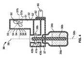
図1、2を参照すると、揮発性物質拡散装置30は一般的にハウジング32を含む。揮発性物質35a、35bを中に有し、揮発性物質35a、35bに接し、容器34a、34bの外へ延伸する芯36a、36bを有する、2つの容器34a、34bは、ハウジング32の内部へ挿入できるようになっている。容器34a、34bは、ハウジング32の内部に挿入され、技術的に周知の任意の手段により保持される。例えば、容器34a、34bはその1つまたは複数の表面上に、ハウジング32の溝、出っ張り、又は開口に嵌合し、保持される突起(図示せず)を含んでもよい。そのような構成は、Weflerの米国意匠特許第393,063号、Pedrottiらの米国特許第6,862,403号、及びDustonらの米国特許第7,032,831号に詳細に記述されている。 Referring to FIGS. 1 and 2, the volatile
容器34a、34bの中の揮発性物質35a、35bは、同一又は異なる揮発性物質35a、35bであってよいし、同一の種類又は異なる種類のものであってもよい。使用される異なる種類の揮発性物質35a、35bとしては、例えば、殺虫剤、昆虫忌避剤、昆虫誘引剤、殺菌剤、カビ又は白カビ抑制剤、芳香剤、殺菌剤、空気浄化剤、アロマセラピー芳香剤、防腐剤、除臭剤、積極的な芳香付与活性物質、エアフレッシュナー、脱臭剤など、およびその組合せが含まれる。同一種類の2つの揮発性物質35a、35bが使われる必要はない。例えば、殺虫剤と芳香剤が使われてもよいし、殺菌剤と忌避剤が使われてもよいし、その他の揮発性物質35a、35bの任意の種類の組合せが用いられてもよい。 The
再び図1、2を参照すると、揮発性物質拡散装置30aは、揮発性物質35a、35bを気化させるための芯36a、36bに隣接して配設されたヒータ38a、38bを含む第1のチャンバ37を備えている。揮発性物質は毛細管現象によって芯36a、36bを通って、芯36a、36bの上端部40a、40bまで移動する。芯36a、36b及びヒータ38a、38bは、第1のチャンバ37内部に形成されたチャネル41a、41b(41bのみ図示)内にある。チャネル41a、41bは芯36a、36bの直径よりも大きい直径を有し、芯36a、36bと、各チャネル41a、41bを形成している円筒壁43a、43b(43bのみ図示)との間に、空隙42a、42b(42bのみ図示)を提供する。 Referring again to FIGS. 1 and 2, the volatile material diffusing device 30a includes a first
ファン50がハウジング32の後部52の第2のチャンバ51の内部に配設され、チャンバ51を構成する前壁55に、スロット又は通風孔54がファン50に対向して配設されている。ファン50は拡散装置30の垂直軸56沿いに、芯36a、36b及びヒータ38a、38bの少し上に配設されている。図1、2を参照すると、ファン50の長手方向の軸57aは、拡散装置30の長手軸57bに一致し、芯36a、36bの軸58a、58bと直交する。ここで芯36a、36bの軸58a、58bは拡散装置30の垂直軸56と平行である。ファン50からの空気は通風孔54に向けられ、芯36a、36bから放出された、気化した揮発性物質35a、35bを拡散装置30から離れる方向へ移動させる。ファン50は、芯36a、36b、及びヒータ38a、38bの冷却も行う。詳細は以下で述べる。 The
図1、2をもう一度参照すると、拡散装置30は、必ずしも必要ではないが、好ましくは2つの差し込み60(1つのみを図示)を有し、これは拡散装置の背面62から突き出ていて、通常の電気コンセントに差し込まれる。このように、拡散装置30には直流が供給されて、ヒータ38a、38b、及びファン50が運転される。任意選択で、拡散装置は電池で駆動されてもよい。 Referring once again to FIGS. 1 and 2, the
図1及び2の拡散装置30は、1つ芳香剤又は類似のものが使用される場合に、特定の揮発性物質35a、35bに対する馴化を防ぐように作用する。拡散装置30はまた、2つの揮発性物質35a、35bの混合量を制限する。特に、揮発性物質35a、35bは交互に放出される。拡散装置30が電気コンセントに差し込まれると、第1のヒータ38aが起動して第1の揮発性物質35aを放出する。第1の期間が経過すると、第1のヒータ38aが停止し、第2のヒータ38bが起動して、第2の揮発性物質35bを第2の期間だけ放出する。第2の期間が終了すると、第2のヒータ38bは停止し、第1のヒータ38aが起動する。そうして、このサイクルが、拡散装置30を電気コンセントから抜くまで繰り返される。このサイクルにおいて、第1のヒータ38aと38bの起動、停止は同時に行われる。この代わりに、ヒータ38a,38bの一方の停止と、その次のヒータ38a,38bの起動との間に、第3の期間を置き、この第3の期間にはいずれのヒータも起動されないようにしてもよい。更にまた別に、ヒータ38a、38bの一方の起動と、ヒータ38a、38bのもう一方の停止との間に、第4の期間を設け、この第4の期間の間は揮発性物質35a、35bが重複生成されるようにしてもよい。 The diffusing
第1及び第2の期間の長さを同じにして、ヒータ38a、38bのそれぞれが同じ長さの期間起動するようにしてもよい。あるいは、第1及び第2の期間の長さが異なってもよい。第1及び第2の期間の長さは、約10秒から約3時間、より好ましくは約15分から約2時間、最も好ましくは約50分から約90分、の間である。 The lengths of the first and second periods may be the same, and each of the
図1及び2の拡散装置30において、例えば2つの芳香剤などの2つの揮発性物質35a、35bを利用する場合、第1のヒータ38aを停止してから第2のヒータ38bを起動し、かつ第2のヒータ38bを停止してから第1のヒータ38aを起動したとしても、あるいは、第1及び第2のヒータ38a、38bを同時に起動、停止したとしても、揮発性物質35a、35bの放出が重なることがしばしばある。この理由は、停止したヒータ38a、38bとそれに係わる芯36a,36bの冷却にはある時間を要するからである。この冷却期間の間、芯36a、36b及びヒータ38a、38bは周囲温度よりもかなり高く、定常状態の温度に戻るまでには長時間を要するために、停止したヒータ38a、38bに係わる揮発性物質35a、35bは気化し続ける。更に、定常状態の温度も周囲温度より十分高いことがあり、ヒータ38a、38bが停止している期間中、停止したヒータ38a、38bに係わる揮発性物質35a、35bの存在が検出されることがある。この2つの揮発性物質35a、35bが重なって放出されることは、ユーザが1つだけの揮発性物質35a、35bが検知されることを好むこと、及び/又は揮発性物質35a、35bが相溶性を持たないことによって、好ましくない場合が多い。 In the case of using two
本開示の拡散装置30内に配設されるファン50は、揮発性物質35a、35bの放出の重なりを最小化する方法を提供する。特にファン50からの空気流が、通気孔54を通ってチャネル41a,41bの上へ流れ、それによって煙突効果により、チャネル41a,41bにより形成される空隙42a,42bを通って空気を下へ流す。チャネル41a、41bを通る空気流は芯36a、36b、及びヒータ38a、38bを冷却する。テスト手順が設けられて、それに従って、揮発性物質35a、35bの放出の重なりを最小化するのにファン50が有効であることが示された。図1の拡散装置30に類似したマルチ芳香拡散装置上でテスト手順が実行された。これは2つの容器34a、34bを有し、そこから延伸し、容器34a、34b内部の揮発性物質35a、35bに接している芯36a,36bをそれぞれ持っている。容器34、34bが拡散装置30に差し込まれると、芯36a、36bの上部40a、40bはそれぞれリングヒータ38a、38bの内部に配設される。ファン50は、図2に示すように、芯36a、36bとヒータ38a、38bの上方、かつ後部に配設される。すべてのテストの間、ファン50は約2000〜2200rpmの間で回転された。第1及び第2の熱電対が、芯36a、36bの軸58a、58bにそれぞれ一致する、第1及び第2の芯36a、36bの中央部分に差し込まれ、テスト手順中の様々な時点における芯38a、38bのそれぞれの温度が計測された。 The
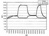
図3では、テスト手順としてまずベースラインテストを行い、ファンが停止している場合の第1及び第2の芯36a、36bの温度を調べた。結果は以下の通りであった。時刻が約13:45:00から約14:00:00までの間の温度の急騰を除いて、芯36a,36bはそれぞれ最高温度約57〜58℃(約135〜136°F)に達し、芯36a,36bはそれぞれ最低温度約30℃(約86°F)に達した。この時周囲温度は約21℃(約70°F)であった。このベースラインテストは、ヒータ38a、38bが停止している場合でも、関係する芯36a,36b、及び/又はヒータ38a,38bの内部には残留熱がまだあることを示している。この残留熱は、芯36a,36b、及び/又はヒータ38a,38bが急速には冷却されないか、及び/又は、起動されたヒータ38a,38bが停止したヒータ38a,38bに係わる芯36a,36bへ何らかの熱を移動するか、のいずれかによって生じる可能性がある。前述の温度の急騰は、拡散装置30の起動による異常によるものと考えられる。このことは、ヒータ38a,38bが切り替わっても、温度の急騰がもう起きなかった事実によっても正しいと考えられる。 In FIG. 3, a baseline test is first performed as a test procedure, and the temperatures of the first and
次に図4〜9を参照すると、ファン50の異なる位置でのテストが行われた。これは、停止している芯36a,36bを冷却し、その一方で対応する揮発性物質35a、35bの放出がユーザにとって不十分とならないように、起動している芯36a,36bはあまり冷却しないようにするための、最も効率のよいファン50の位置を決定するためのテストである。 Referring now to FIGS. 4-9, tests were performed at different locations of the
図4から分かるように、ファン50は、拡散装置30の長手軸57bに対して約45度の角度で上に向けられている。ファン50が傾けられているこの実施形態においては、ファン50は更に、芯36a,36bの軸58a、58bの間の中心点の方向へ向けられている。そうして、芯36a,36bのそれぞれに等量の空気流が向けられるようにする。図5から分かるように、テストの期間において、芯36a,36bは最高温度約43〜45℃(約109〜113°F)に達し、芯36a,36bのそれぞれは最低温度約25℃(約77°F)に達した。この時周囲温度はやはり約21℃(約70°F)であった。図5のデータから明らかなように、芯36a、36bの最低温度と最高温度のいずれも、図3に示すファン50がない場合の芯36a,36bの最低温度と最高温度より低い。ヒータ38a、38bが停止している時、それらに係わる芯36a,36bは概ねよく冷却されて、関係する揮発性物質35a、35bは殆どのユーザには感知されない。 As can be seen from FIG. 4, the
図6を参照すると、ファン50は、拡散装置30の長手軸57bに対して約22.5度の角度で上に向いている。図7から分かるように、テストの期間において、芯36a、36bは最高温度約38〜48℃(約100〜118°F)に達し、芯36a、36bのそれぞれは最低温度約24〜26℃(約75〜79°F)に達した。この時周囲温度は約21℃(約70°F)であった。ここでも図7のデータは、ヒータ38a、38bが起動、停止している場合、ファン50は芯36a、36b及び/又はヒータ38a、38bを冷却していることを示している。起動しているヒータ38a、38に係わる芯36a、36bが冷却されすぎて拡散装置からのユーザの楽しみが減ることのないようにしつつ、停止しているヒータ38a、38に係わる芯36a、36bが十分に冷却されて、停止しているヒータ38a、38に係わる揮発性物質35a、35bが殆どのユーザにはほぼ感知されないようになる角度を見つけることが肝要である。 Referring to FIG. 6, the
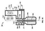
他のファン50の向きが図1と図8に示されている。図1では、詳細を前述したように、拡散装置30の長手軸57bに対してファン50は上にも下にも全く角度がついていない(0度)。図8は、拡散装置30の長手軸57bに対してファン50は下に約5度傾いている。 The orientation of the
本明細書の実施形態では通気孔54の組の数が示されているが、本明細書の任意の実施形態胃において、任意の数の通気孔54が用いられてよい。 Although the number of sets of
本明細書においてファン50は、拡散装置30の長手軸57bに対して上に45度、長手軸57bに対して上に22.5度、長手軸57bに対して0度、及び長手軸57bに対して下に5度傾いて示されているが、これ以外の角度も可能である。特に、拡散装置30の長手軸57bに対して下に約45度と上に約45度との間の任意の角度で配設することが可能である。 In this specification, the
芯36a、36bの一方を他方よりもより強く冷却したい場合には、本明細書の任意の実施形態においてファン50を、拡散装置30の長手軸57bからハウジング32の側壁64a、64bの方向へ向けてもよい。特にファン50を、長手軸57bに対して約0度から約45度の間の角度で、いずれかの側壁64a、64bの方向へ向けてもよい。上記と同一のテスト手順を参照して、図10ではファン50は長手軸57b(図1)に対して上にも、下にも角度をつけないで(角度0で)、図9に示すように、第2の芯36bの方へ向けた。図10に示すように、第2の芯36bは第1の芯36aよりも強く冷却されている。事実、第2の芯36bは最高温度約28℃(約82°F)であり、最低温度は約23℃(約73°F)であった。この時、周囲温度は約21℃(約70°F)であった。第1の芯36aは最高温度約47℃(約117°F)であり、最低温度は約27℃(約81°F)であった。 If one of the
図11の結果に関しては、ファンを拡散装置30の長手軸57bに対して下方向へ5度曲げ(図8)、かつ図9に示すように第2の芯36bの方向へ向けた状態で拡散装置30を用いた。結果は、第1の芯36aの最高温度が約45℃(約113°F)であり、最低温度が約27℃(約81°F)であった。第2の芯36bは最高温度約26℃(約79°F)であり、最低温度は約22℃(約72°F)であった。この時、周囲温度はまた約21℃(約70°F)であった。 As for the result of FIG. 11, the fan is bent 5 degrees downward (FIG. 8) with respect to the
図9においては、ファン50は長手軸57bに対して第2の芯36bの方に曲げられているように示されているが、ファン50は第1の芯36aの方へ向ける事もできる。図9〜11の実施形態の狙いは、芯36a、36bの1つを他方よりはるかに速く冷却すること、及び/又は芯36a、36bの1つへ与える熱量を他方より全体として少なくすること、である。2つの異なる揮発性物質35a、35bが利用される場合、又は単に揮発性物質35a、35bの一方の放出量を他方より少なくしたい場合に、そうすることが望まれる。 In FIG. 9, the
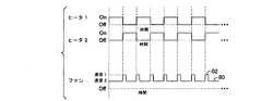
ファン50に連続的に電力が供給されて、ファン50が連続的な空気流を供給するように運転されてもよい。ファン50は単一の速度で運転されてもよく、その場合には上記の一連の手順の中で、スピードは変化しない。あるいはまた、電力が間歇的に供給されて、ファン50が空気の間歇的流れを生成してもよい。そのような運転モードが図12に示されている。図12は、交互のシークエンスを通して同時に起動と停止が行われる、第1及び第2のヒータ38a、38bを示す。図12に更に示されるように、それぞれのヒータ38a、38bが停止した後に、期間の5分の1の間ファン50に電力が供給される。ファン50からの空気流の速度、ファン50の角度、周囲温度等により、5分の1の期間の長さは、約30秒から約5分の間である。 Power may be continuously supplied to the
図13に示すように他の実施形態においては、ヒータ38a、38bは図12と同じ様に通電されるが、ファン50は連続的に通電されている。この運転モードでは、ファン50の速度は第1の速度80と第2の速度82の間を交互に変化する。ヒータ38a、38bが停止すると直ちにファン50が5分の1の期間の間だけ通電されて第2の速度82で動作し、その他の時間は、第1の速度80で動作するように通電される。第1の速度80と第2の速度82は互いに異なり、第2の速度82は好ましくは第1の速度80より大きく、本実施形態においてはいずれの速度も0rpmより大きい。第1の速度80よりも大きい第2の速度は、対応するヒータ38a,38bの停止の直後に芯36a,36bを冷却するのみならず、起動されたヒータ38a,38bに対応する揮発物質35a,35bの集中放出をさせる。第2の速度82より小さい第1の速度80はまた、放出される揮発性物質35a、35bの量を調整し、揮発性物質35a、35bの集中放出が馴化を最小化する助けとなるようにする。 As shown in FIG. 13, in other embodiments, the
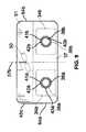
図14〜16を参照すると、1つのファン50の代わりに2つのファン100a、100bが交互に使用されてもよい。図14を参照すると、それぞれのファン100a、100bは、それぞれに1つの芯36a、36b及び1つのヒータ38a、38bに整列している。ヒータ38a、38bは本明細書で記述する任意の方法で通電されてもよい。ファン100a、100bの運転モードの例として、図15、16を参照すると、図12、13でヒータ38a、38bが交互に用いられたのと同じようにヒータ38a、38bが交互に用いられる。ファン100a、100bもまた自動的に交互に使用され、関連するヒータ38a、38bが停止すると、そのヒータ38a、38bに係わるファン100a、100bが起動される。図15では、関連するヒータ38a、38bが停止している間中、ファン100a、100bが起動しているように示されている。その一方、図16では、関連するヒータが停止しているとき、その期間の5分の1の長さだけファン100a、100bが起動している。 Referring to FIGS. 14 to 16, two
ヒータ38a,38bと、ファン50又は100a、100bの起動、停止を図示している図12、13、15、16における運転モードのグラフ表示の例は、ヒータ及びファンの起動及び停止の例を示すためのものであり、それにより制限することは意図されていない。特に、これまでに詳細を述べたように、ヒータ38a、38bはいかなる仕方で交互に動作させることも可能である。 Examples of operation mode graph display in FIGS. 12, 13, 15 and 16 illustrating the start and stop of the
図14を再び参照すると、壁もしくはその他の遮蔽構造の形態をしたシールド110が第2のチャンバ51の外側で第1のファン100aと第2のファン100bとの間に配設されている。これは、第1のファン100aからの空気流が第2の芯36b及び第2のヒータ38bへ流れることを阻止し、第2のファン100bからの空気流が第1の芯36a及び第1のヒータ38aへ流れることを阻止するためのものである。 Referring again to FIG. 14, a
図17、18を参照すると、一組のルーバ120が本明細書で述べた通風孔54を置き替えている。ルーバ120は図17ではファン50の軸57aに平行に表示されている。調整機構122がハウジング32上に配置され、ユーザがルーバ120を調節することができる。このようにして、拡散装置30の長手軸57bに対して下向きに約45度の角度から、長手軸57bに対して上向きに約45度の角度までの間の任意の角度にルーバ120を動かすことができる。図18は、約30度下向きの角度を有する位置に調節されたルーバ120を表している。図17には空気流を方向づけるものとしてルーバ120が示されているが、空気流の方向付けが可能な任意の手段を利用することが可能である。 Referring to FIGS. 17 and 18, a set of
別の独自のひと組のテストが図19〜21に示された揮発性物質拡散装置30で行われた。ここで、これらの拡散装置30は、図2、4、6、8の拡散装置30と類似であるが、ファン50の角度が違っている。また、前述したものと同一のテスト手順が利用された。図19〜21では、拡散装置30の長手軸57bに対して、ファン50はそれぞれ36度、21度、−9度の角度となっている。図19〜21の各拡散装置30が、ある長さの期間テストされ、その結果がそれぞれ図22〜24に記録された。図22を参照すると、これは長手軸57bに対して約36度の角度のファン50の場合のテストを表しており、芯36a、36bは最高温度約64〜66℃(約147〜151°F)に達し、芯36a、36bのそれぞれは最低温度約33℃(約91°F)に達した。図23は図20の拡散装置30のテスト結果を表しており、これはファン50が長手軸57bに対して約21度の角度となっている。このテストでは、芯36a、36bは最高温度約53〜61℃(約127〜142°F)に達し、芯36a、36bは最低温度約28〜32℃(約82〜90°F)に達した。次に図24を参照すると、これは長手軸57bに対して約−9度の角度のファン50の場合について行われたテストであり、芯36a、36bは最高温度約47〜57℃(約117〜135°F)に達し、芯36a、36bは最低温度約25〜27℃(約77〜81°F)に達した。図19〜24の3つのテストはすべて約22℃の周囲温度の下で行われ、周囲温度の実測値は約22℃又は約23℃(約72°F又は約73°F)であった。本明細書のその他のテスト結果と同様に、長手軸57bに対するファン50の配設角度が、芯36a、36b、及び/又はヒータ38a、38bの冷却速度に影響を与えることが明らかである。 Another unique set of tests was performed with the
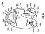
揮発性物質拡散装置130の更なる実施形態が図25〜28に示されている。拡散装置130は、本明細書の任意の拡散装置30と同様であり、同じように作用する。図25から分かるように、拡散装置130は2つの容器を保持するためのハウジング132を含み、その容器は、内部に揮発性物質135a、135bと、容器から延伸する芯136a、136bと、を有する。図28で最もよく分かるように、ハウジング132は背面部138とカバー部140と取付構造142とを含む。取付構造142は背面部138に取り付けられ、カバー部140は背面部138と取付構造142とに組み付けられて、取付構造142が背面部138とカバー部140との間に配設されるようになっている。図28を参照すると、取付構造142は前部144aと後部144bとを含み、前部144aはそこを通って第1のチャネル150a、150bが延伸する水平面146と、第1のチャネル150a、150bを形成する構造の上部に配設されたリングヒータ152a、152bと、リングヒータ152a、152bの上に配置された第2のチャネル154a、154bとを含んでいる。ヒータ152a、152bは第1のチャネル150a、150bの上方に配設され、第2のチャネル154a、154bはヒータ152a、152bの上方に配設される。リングヒータ152a、152bを貫通して形成されるリングチャネル156a、156bと、第1のチャネル150a、150bと、第2のチャネル154a、154bとは、すべて垂直軸158a、158bに沿って整列している。ファン171を内部に有するファン支持構造170は、取付構造142の後部144bから第2のチャネル154a、154bの上方に延在し、半円構造172がファン170の下で第2のチャネル154aと154bとの間に配設されている。半円構造172は、ファン170からの空気流が、拡散装置130を貫通して循環するのを防止している。 A further embodiment of the
図28から分かるように、プリント回路基板(PCB)180が取付構造142の後部144b内部に固定され、拡散装置130を制御するためのすべての回路を含んでいる。第1及び第2の発光ダイオード(LED)182a、182bが、PCB180の上端184から延在し、第2のチャネル154a,154bの背面186a、186bの付近に配設される。LED182a、182bが点灯されると、それぞれ背面186a、186bを通して光が見える。LED182a、182bは、ヒータ152a、152bがそれぞれ作動している場合に点灯されてもよい。別の方法としては、光源187が拡散装置130内部の任意の場所に配設されてもよい。図25及び27に見られるように光源187は、ディフューザとしての単レンズ191と共に配設された、第1の色のLED189aと第2の色のLED189bとを含んでよい。LEDは任意の色であってよいが、特定の実施例では、第1のLED189aは赤で、第2のLED189bは青である。第1のヒータ152aが起動している場合には、第1のLED189aが点灯して赤色を発し、第2のヒータ152bが起動している場合には、第2のLED189bが点灯して青色を発し、ヒータ152aもヒータ152bも起動してない場合には、LED189aもLED189bも点灯せず、ヒータ152aとヒータ152bの両方が起動している場合には、LED189aとLED189bの両方が点灯して混合された紫色を生じる。この機能は、どの揮発性物質が放出されているかをユーザに視覚的な色表示で示し、又いつ揮発性物質が変わったかの表示を与える。同様の機能を提供するために、任意選択で、複数の色を発光する単一のLEDを利用することもできる。 As can be seen in FIG. 28, a printed circuit board (PCB) 180 is secured within the
LED182a、182b、及び/又は光源187に追加して、又はその代わりに、図27に見られるような光源200a、200bを容器134a、134bの後ろの配設して、点灯した場合に容器134a、134b及びその中の揮発性物質135a、135bを透過して光源200a、200bの光が輝くようになっていてもよい。光源200a、200bは1つのLED201a、201bを含む。LED201a、201bはカラー光又は白色光を発してもよいし、及び/又はLED201a、201bのそれぞれが同じ又は別のカラー光を放射してもよい。任意選択で、光源200a、200bは任意の数のLEDを含んでもよく、又その内のいずれがカラー光であってもよい。ある実施形態では、光源200a、200bのそれぞれが複数の異なる色のLEDを有し、点灯してライトショウを演出してもよい。特定のヒータ152a、152bが起動している場合、関連する光源200a、200bが起動されて、どの揮発性物質135a、135bが放出中であるかをユーザに知らせる。 In addition to or instead of the
図28を参照すると、光源203が水平面146の下面に配設されてもよい。このような場合、光源203は下向きに容器134a、134bを照らす。そのような実施形態では光源203は複数のLED又は1つの多色LEDのいずれかを含む。揮発性物質が自動的に変わる際に、光源203から放出される色も変化してよい。ヒータ152a、152bが同時に起動、停止し、光源203が3色LEDを含む、非制限的な実施例において、第1のヒータ152aが起動されて第1の揮発性物質135aを放出している間、光源203から赤色光が放出される。第1のヒータ152aが停止し、第2のヒータ152bが起動すると、赤色光が青色光で置き換えられか、青色光に変化する。光源203のこのような色の変化は、新しい揮発性物質が放出されていることをユーザに知らせる。ただしどの揮発性物質が放出中であるかを必ずしも知らせるものではない。 Referring to FIG. 28, the
図28を更に参照すると、強度レベルスイッチ188がPCB180から延伸し、ハウジング132の背面部138の開口192を介して延在するアクチュエータアーム190を含んでいる。ボタン194がアクチュエータアーム194上に配設されて、スイッチ188の位置を変えられるようになっている。スイッチ188の位置はPCB180で感知され、そのスイッチ188の位置に基づいて揮発性物質135a、135bを放出する強度レベルが変わる。強度レベルの変化と共に、LED、及び/又は光源182a、182b、189a、189b、201a、201b、及び/又は203の強度が変化してもよい。特に拡散装置130が最高強度レベルに設定されている場合、起動されているヒータ152a、152bに係わるLED及び/又は光源182a、182b、189a、189b、201a、201b及び/又は203は、その最高強度レベルで点灯され、拡散装置130が最低強度レベルに設定されている場合、起動されているヒータ152a、152bに係わるLED及び/又は光源182a、182b、189a、189b、201a、201b及び/又は203は、その最低強度レベルで点灯され、その間の任意の強度レベルに対しては、起動されているヒータ152a、152bに係わるLED及び/又は光源182a、182b、189a、189b、201a、201b及び/又は203は、それぞれの強度レベルで点灯される。任意選択で、強度レベルスイッチ188が2つ利用されてもよい。その場合、それぞれのスイッチは特定のヒータ152a、152bに係わる特定の揮発性物質135a、135bの強度レベルを制御する。 Still referring to FIG. 28, an
強度レベルスイッチ188に代わって、あるいはそれに追加して、揮発性物質選択スイッチ(図示せず)又は別のタイプのスイッチが利用されてもよい。揮発性物質選択スイッチにより、第1の揮発性物質135a、第2の揮発性物質135b、又は両方の揮発性物質135a、135bを交互の順番で放出するようにユーザが選択できる。 In place of or in addition to the
拡散装置130又は本明細書における任意の拡散装置は、拡散装置130中での揮発性物質の量を検知する臭いセンサを含んでよい。センサが揮発性物質を検出しなくなった場合、つまり、容器136a、136bが空か、その中の揮発性物質135a、135bが僅かしかなくなった場合に、センサがPCB180に通知する。その通知に呼応して、1つまたは複数の容器136a、136bの交換が必要であることを、LED182a、182b及び/又は189a、189bを停止するか、ヒータ152a、152bを停止するか、及び/又はLED182a、182b及び/又は189a、189bを黄色や黒色等の異なる色で点灯することにより、PCBがユーザに知らせる。別の実施形態では、拡散装置130又は本明細書における任意の拡散装置は、図25に示す薄膜202a、202bを容器134a、134bの内部に、好ましくは、容器134a、134bの内部表面の少なくとも一部に沿って、含んでもよい。揮発性物質135a、135bが容器134a、134b内に配設されると、薄膜202a、202bは濡れて透明になる。揮発性物質135a、135bが容器134a、134bから分与されるに従い、薄膜202a、202bは乾燥し始め不透明となる。薄膜202a、202bが不透明になる性質が、容器134a、134bの交換が必要であることをユーザに示す。LED201a、201b(図27)が容器134a、134bの背面に配設されている場合には、容器134a、134が充満であれば(従って場合薄膜202a、202bが透明であれば)LED201a、201bからの光は点光源のように見え、容器134a、134が空又は空に近い(従って場合薄膜202a、202bが不透明である)場合にはLED201a、201bからの光は混光光源のように見える。 The diffusing
図28から分かるように、プラグアセンブリ210が取付構造142の後部144bに接続され、ハウジング132の背面部138にある開口212を通って突き出ている。プラグアセンブリ210の電気差し込み214a、214bが電気コンセントに差し込まれて拡散装置130に電力を供給する。 As can be seen from FIG. 28, the
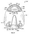
図25〜27を参照すると、ハウジング132の背面部138は複数の流入孔220を含み、カバー部140は複数の流出孔222を含む。通風孔220,222は特定の半円形形状で示されているが、任意の好適な形状が可能である。ファン170は流入孔220と流出孔222との間に配設され、ファンが回転すると空気は流入孔220から引き込まれて流出孔222から押出され、揮発性物質が放出されるとそれを循環させる。 Referring to FIGS. 25 to 27, the
図28を参照すると、各容器134a、134bから延伸する芯136a、136bの部分を、それぞれ第1のチャンネル150a、150bとリングチャネル156a、156bとを通って挿入することにより、図25に示されるように容器134a、134bは、拡散装置130の中に挿入される。この時、芯136a、136bは元のままに在り、芯136a、136bと、第1のチャンネル150a、150bとリングチャネル156a、156bを形成する壁との間に空隙が形成される。ファン170が起動されると、ファンからの空気流が第2のチャネル上を流れ、煙突効果を生じて空気が第2のチャネルを介して下方向に流れ、芯136a、136bと、第1のチャンネル150a、150bとリングチャネル156a、156bとの間で形成される空隙を通り、それにより芯136a、136b、及び/又はヒータ152a、152bを冷却する。図25、27、28を参照すると、容器134a、134bは、対向する貝殻形状の開口240a、240bと貝殻形状の溝242a、242bとによって、拡散装置130内部に保持される。特に容器134a、134bが拡散装置130に挿入される際、それぞれの容器134a、134bの相対向する側に在る貝殻形状の突起244a、244bが、相対する開口240a、240bと溝242a、242bの中に滑り込む。ここで、開口240a、240bと溝242a、242bを形成する壁により構成される干渉を克服するためには容器134a、134bを下方向へ引張らなければならない。 Referring to FIG. 28, the portion of the
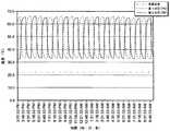
図25〜28の拡散装置130が、ファンを起動した場合と、ファンを停止した場合とでテストされた。図29と図30のテスト結果は、前述したのと同じ方法を用いて生成された。図29のグラフは、ファン170を停止した場合の拡散装置130の、温度対時間の関係を示す。結果からわかる通り、芯136a,136bのそれぞれは最高温度約80〜85℃(約176〜185°F)であり、テスト期間中のそれぞれの芯の最低温度は約36〜39℃(約97〜102°F)であった。次にファン170が起動している図30では、芯136a、136bの最高温度は約63〜67℃(約145〜153°F)であり、同じ期間中の芯136a、136bの最低温度は約29〜31℃(約84〜88°F)であった。図29と30のテスト期間中の周囲温度は約20°C(約68°F)であった。上記のテスト結果と同じように、ファン170は芯136a、136b及び/又はヒータ152a、152bも冷却し、停止しているヒータ152a、152bに係わる揮発性物質の放出量を、好ましくはユーザが感知しない程度にまで最小化する。 The
これまで述べた実施形態ではファン50、100a、100b、又は170が利用されているが、空気流を提供する任意の手段を利用することができる。その手段としては、軸流タイプのファン、遠心力タイプのかご型ブロア、蠕動ポンプ、又はその他の技術的に周知のファン又はポンプがあるが、これに限られるものではない。 In the embodiments described so far,
本出願は、1つ以上の揮発性物質を放出する拡散装置を提供する。ここで、揮発性物質は交互に放出される。揮発性物質はヒータによって気化され、ファンが気化した物質の拡散装置からの排出を支援する。ファンからの空気流は、停止した後のヒータ及びそれに係わる、揮発性物質を含む芯も冷却し、揮発性物質の重複を最小化するようにする。1つまたは複数のLEDが拡散装置に組み込まれていて、どの揮発性物質が放出中であるかを表示し、視覚効果を与え、放出されている揮発性物質が変わったことを表示し、及び/又は揮発性物質の入っている容器を交換する必要があることを知らせたりする。 The present application provides a diffusion device that emits one or more volatile materials. Here, the volatile substances are released alternately. Volatile substances are vaporized by the heater, and the fan assists the discharge of the vaporized substance from the diffuser. The air flow from the fan also cools the heater after it has stopped and the associated volatile material containing core, minimizing the overlap of volatile material. One or more LEDs are incorporated into the diffuser to indicate which volatile material is being emitted, provide a visual effect, indicate that the volatile material being emitted has changed, and And / or inform that the container containing the volatile material needs to be replaced.
当業者には以上の説明を読めば、多数の修正が明らかであろう。従って、この説明は、例示的なものとしてのみ解釈すべきであり、その目的は、当業者が本発明を行い、かつ使用できるようにすると共に、当業者に発明実施の最良の形態を教示することである。ここで引用したすべての特許および他の参照は、その全体が、参照により組み込まれている。添付の特許請求の範囲内にあるすべての変更についての独占権が、留保されている。 Many modifications will be apparent to those of skill in the art upon reading the above description. Accordingly, this description is to be construed as illustrative only and is for the purpose of enabling those skilled in the art to make and use the invention and to teach those skilled in the art the best mode of carrying out the invention. That is. All patents and other references cited herein are incorporated by reference in their entirety. Exclusive rights for all changes within the scope of the appended claims are reserved.
Claims (20)
Translated fromJapanese第1及び第2の揮発性物質を保持し、且つ、第1及び第2の芯をそれぞれに有する第1及び第2の容器であって、前記第1及び第2の芯は各揮発性物質に接し且つ各容器の外へ延伸し、前記容器は前記ハウジング内に挿入されて取り外し自在に取り付けられている第1及び第2の容器と、
前記ハウジング内に前記第1及び第2の芯にそれぞれ隣接して配設され、前記第1及び第2の揮発性物質をそれぞれ気化させるための第1及び第2のヒータと、
前記ハウジング内に配設された空気流を提供する手段であって、前記空気流提供手段からの空気が気化した揮発性物質を前記ハウジングの外へ輸送するようになった手段と、
を備える揮発性物質拡散装置であって、
前記ヒータは交互に通電され、ヒータが停止している場合には前記空気流提供手段が前記停止中のヒータに係わる芯を冷却するようになっていることを特徴とする揮発性物質拡散装置。A housing;
1st and 2nd container which hold | maintains 1st and 2nd volatile substance and has 1st and 2nd core, respectively, Comprising: Said 1st and 2nd core is each volatile substance And extending out of each container, the container being inserted into the housing and removably attached, and first and second containers;
First and second heaters disposed in the housing adjacent to the first and second cores, respectively, for vaporizing the first and second volatile substances, respectively;
Means for providing an air flow disposed within the housing, wherein the volatile material vaporized by air from the air flow providing means is adapted to transport out of the housing;
A volatile substance diffusion device comprising:
The heater is energized alternately, and when the heater is stopped, the air flow providing means cools the core related to the stopped heater.
前記第1の速度が前記第2の速度より大きく、前記第1の速度はより広範な検出域に対して前記揮発性物質を大量放出し、且つ、前記第2の速度はより狭い検出域により集中した放出を提供するようになっていることを特徴とする、請求項1に記載の装置。The air flow providing means is a fan that alternately takes a first speed and a second another speed,
The first speed is greater than the second speed, the first speed releases a large amount of the volatile material over a wider detection area, and the second speed is due to a narrower detection area. Device according to claim 1, characterized in that it provides a concentrated discharge.
第1及び第2の揮発性物質を保持しかつ第1及び第2の芯をそれぞれに有する第1及び第2の容器であって、前記第1及び第2の芯は各揮発性物質に接しかつ各容器の外へ延伸し、前記容器はハウジング内部に挿入されて取り外し自在に取り付けられている第1及び第2の容器と、
前記ハウジング内に前記第1及び第2の芯にそれぞれ隣接して配設され、前記第1及び第2の揮発性物質をそれぞれ気化させるための第1及び第2のヒータと、
前記ハウジング内に配設されたファンであって、前記ファンからの空気が気化した揮発性物質を前記ハウジングから排出するように配設されたファンと、
を備える揮発性物質の拡散装置であって、
前記第1のヒータが停止し、かつ前記第2のヒータが起動されている場合に、前記ファンは前記第1の芯を冷却して前記第1の芯の温度を下げ、且つ前記第1のヒータを冷却して、前記第2の揮発性物質が放出されている間における前記第1の揮発性物質の放出量を最小化するように作用することを特徴とする、揮発性物質の拡散装置。A housing;
First and second containers for holding first and second volatile materials and having first and second wicks, respectively, wherein the first and second wicks contact each volatile material. And extending out of each container, the container being inserted into the housing and removably attached, and first and second containers;
First and second heaters disposed in the housing adjacent to the first and second cores, respectively, for vaporizing the first and second volatile substances, respectively;
A fan disposed in the housing, wherein the fan is disposed so as to discharge from the housing a volatile substance in which air from the fan is vaporized;
A volatile substance diffusion device comprising:
When the first heater is stopped and the second heater is activated, the fan cools the first core to lower the temperature of the first core, and the first heater A diffusion device for a volatile substance, characterized in that the heater is cooled so as to minimize the emission amount of the first volatile substance while the second volatile substance is being emitted. .
ハウジングと、前記ハウジングに取り外し自在に取り付けられた2つの容器と、を有し、揮発性物質と、前記揮発性物質に接触し、前記容器の外へ延伸する芯と、を含む揮発性物質拡散装置を提供し、
前記芯に隣接して配設されたヒータを提供し、
前記ヒータが停止している場合に前記ヒータ及び隣接する芯を冷却するために、前記芯及び前記ヒータの上方に距離を離してファンを提供する、
ステップを備える方法。A method for preventing undesired mixing of volatile substances, comprising:
A volatile substance diffusion having a housing and two containers removably attached to the housing, the volatile substance including a volatile substance and a core that contacts the volatile substance and extends out of the container Providing equipment,
Providing a heater disposed adjacent to the core;
Providing a fan at a distance above the wick and the heater to cool the heater and adjacent wick when the heater is stopped;
A method comprising steps.
Applications Claiming Priority (3)
| Application Number | Priority Date | Filing Date | Title |
|---|---|---|---|
| US861307P | 2007-12-20 | 2007-12-20 | |
| US6757108P | 2008-02-28 | 2008-02-28 | |
| PCT/US2008/013813WO2009085170A1 (en) | 2007-12-20 | 2008-12-18 | Volatile material diffuser and method of preventing undesirable mixing of volatile materials |
Publications (1)
| Publication Number | Publication Date |
|---|---|
| JP2011508621Atrue JP2011508621A (en) | 2011-03-17 |
Family
ID=40386355
Family Applications (1)
| Application Number | Title | Priority Date | Filing Date |
|---|---|---|---|
| JP2010539473APendingJP2011508621A (en) | 2007-12-20 | 2008-12-18 | Volatile material diffusion apparatus and method for preventing unwanted mixing of volatile materials |
Country Status (9)
| Country | Link |
|---|---|
| US (1) | US8320751B2 (en) |
| EP (1) | EP2240209B1 (en) |
| JP (1) | JP2011508621A (en) |
| CN (1) | CN101951966B (en) |
| AU (1) | AU2008343917A1 (en) |
| CA (1) | CA2709084C (en) |
| ES (1) | ES2430384T3 (en) |
| MX (1) | MX2010006866A (en) |
| WO (1) | WO2009085170A1 (en) |
Cited By (3)
| Publication number | Priority date | Publication date | Assignee | Title |
|---|---|---|---|---|
| JP2021501870A (en)* | 2017-11-06 | 2021-01-21 | ゼナウラ リミテッドZenaura Limited | Fragrance system |
| JP2023511866A (en)* | 2020-01-15 | 2023-03-23 | エス.シー. ジョンソン アンド サン、インコーポレイテッド | Dispenser with visual display system |
| JP2023047526A (en)* | 2021-09-27 | 2023-04-06 | 株式会社東海理化電機製作所 | scent generator |
Families Citing this family (60)
| Publication number | Priority date | Publication date | Assignee | Title |
|---|---|---|---|---|
| GB0804763D0 (en)* | 2008-03-14 | 2008-04-16 | Givauden Sa | Candle |
| US8412030B2 (en)* | 2009-08-26 | 2013-04-02 | S.C. Johnson & Son, Inc. | Method and apparatus for dispensing a fragrance |
| ES2527300T5 (en)* | 2009-09-21 | 2021-03-03 | Johnson & Son Inc S C | Method of emitting a volatile material from a diffuser |
| US9259499B2 (en)* | 2010-09-15 | 2016-02-16 | Simpletek LLC | Remotely deployable vapor delivery device |
| US8517351B2 (en) | 2011-04-28 | 2013-08-27 | S.C. Johnson & Son, Inc. | Centrifugal fan device |
| US8807538B2 (en) | 2011-04-28 | 2014-08-19 | S.C. Johnson & Son, Inc. | Centrifugal fan device |
| WO2014043639A1 (en)* | 2012-09-14 | 2014-03-20 | The Schawbel Corporation | Dispensing device with fan directed air stream |
| US9474818B1 (en) | 2012-10-22 | 2016-10-25 | Marcus J. Shotey | Air freshener |
| WO2014087173A1 (en)* | 2012-12-07 | 2014-06-12 | Ostrom Elizabeth | A fragrance disperser |
| US11541143B2 (en) | 2013-04-01 | 2023-01-03 | Earl Vaughn Sevy | Pop-out diffuser and mobile-power-base apparatus and method |
| US10507258B2 (en)* | 2013-04-01 | 2019-12-17 | Earl Vaughn Sevy | Compact, mobile, modular, integrated diffuser apparatus and method |
| US8720078B1 (en)* | 2013-08-07 | 2014-05-13 | Fawzi Q.M.A.O.A. Behbehani | Automatic hair dryer with fluid dispenser |
| US9149031B2 (en) | 2013-09-13 | 2015-10-06 | S.C. Johnson & Son, Inc. | Portable area repellent device |
| ES2543893B1 (en) | 2013-12-19 | 2016-05-31 | Zobele Espana Sa | Release system of volatile substances |
| US10220109B2 (en) | 2014-04-18 | 2019-03-05 | Todd H. Becker | Pest control system and method |
| US9474824B2 (en) | 2014-04-18 | 2016-10-25 | Thomas A. Conroy | Method and system of identifying tampering in a scent management system |
| FR3024643B1 (en) | 2014-08-07 | 2016-09-09 | Techno Bam | APPARATUS AND METHOD FOR TRAPPING FLYING INSECTS. |
| US10155059B2 (en) | 2015-03-06 | 2018-12-18 | Personal Care Products, LLC | Volatile material dispenser |
| US9821082B1 (en) | 2015-05-18 | 2017-11-21 | The Yankee Candle Company, Inc. | Connected scent device |
| US9517284B1 (en)* | 2015-07-02 | 2016-12-13 | Xenex Disinfection Services, Llc. | Germicidal apparatuses with configurations to selectively conduct different disinfection modes interior and exterior to the apparatus |
| US9867894B2 (en) | 2015-07-02 | 2018-01-16 | Xenex Disinfection Services, Llc. | Germicidal apparatuses with configurations to selectively conduct different disinfection modes interior and exterior to the apparatus |
| US10433580B2 (en) | 2016-03-03 | 2019-10-08 | Altria Client Services Llc | Methods to add menthol, botanic materials, and/or non-botanic materials to a cartridge, and/or an electronic vaping device including the cartridge |
| US10455863B2 (en) | 2016-03-03 | 2019-10-29 | Altria Client Services Llc | Cartridge for electronic vaping device |
| US10368580B2 (en)* | 2016-03-08 | 2019-08-06 | Altria Client Services Llc | Combined cartridge for electronic vaping device |
| US10357060B2 (en) | 2016-03-11 | 2019-07-23 | Altria Client Services Llc | E-vaping device cartridge holder |
| US10368581B2 (en) | 2016-03-11 | 2019-08-06 | Altria Client Services Llc | Multiple dispersion generator e-vaping device |
| RU2679418C1 (en)* | 2016-04-27 | 2019-02-08 | Конинклейке Филипс Н.В. | Air-purifying apparatus and atmosphere aromatization |
| EP3471784A1 (en)* | 2016-06-16 | 2019-04-24 | CTR, Lda | Wick device for evaporating fragrance having a flow channel |
| US10814028B2 (en) | 2016-08-03 | 2020-10-27 | Scentbridge Holdings, Llc | Method and system of a networked scent diffusion device |
| US10764963B2 (en)* | 2016-10-07 | 2020-09-01 | S. C. Johnson & Son, Inc. | Volatile material dispenser |
| BR102016030146A2 (en)* | 2016-12-21 | 2018-07-17 | Mk Eletrodomesticos Mondial S A | basal chamber and diffuser cap for use of fan repellent refill |
| RU180368U1 (en)* | 2017-11-10 | 2018-06-08 | Антон Геннадьевич Вайс | VENTILATION INSTALLATION FOR INSTALLATION ON THE BUILDING FACADE |
| RU184488U1 (en)* | 2017-11-10 | 2018-10-29 | Антон Геннадьевич Вайс | VENTILATION INSTALLATION FOR INSTALLATION ON THE BUILDING FACADE |
| BR202017025414Y1 (en)* | 2017-11-27 | 2022-04-26 | Mk Eletrodomésticos Mondial S.A. | Constructive arrangement introduced in a fan with a volatilizing function of a repellent substance in a tablet |
| US10709805B2 (en)* | 2017-12-26 | 2020-07-14 | Matthew Aaron Alexander | Wall mountable essential oil diffuser |
| ES3037039T3 (en)* | 2018-01-18 | 2025-09-26 | Procter & Gamble | Method of delivering a volatile composition into the air |
| FR3078608B1 (en) | 2018-03-06 | 2021-07-09 | Techno Bam | APPARATUS AND METHOD FOR TRAPPING PEST FLYING INSECTS |
| CN108718469A (en)* | 2018-07-25 | 2018-10-30 | 中山赛特奥日用科技有限公司 | A kind of diffusion structure and heater of heater |
| US11980702B2 (en)* | 2019-02-27 | 2024-05-14 | Aeron Lifestyle Technology, Inc. | Scent diffusing device |
| US11246954B2 (en)* | 2019-06-14 | 2022-02-15 | The Procter & Gamble Company | Volatile composition cartridge replacement detection |
| US11104451B2 (en)* | 2020-01-17 | 2021-08-31 | B/E Aerospace, Inc | Systems and methods for mitigating condensation in aircraft lighting |
| US11881093B2 (en) | 2020-08-20 | 2024-01-23 | Denso International America, Inc. | Systems and methods for identifying smoking in vehicles |
| US11760169B2 (en) | 2020-08-20 | 2023-09-19 | Denso International America, Inc. | Particulate control systems and methods for olfaction sensors |
| US11636870B2 (en) | 2020-08-20 | 2023-04-25 | Denso International America, Inc. | Smoking cessation systems and methods |
| US12251991B2 (en) | 2020-08-20 | 2025-03-18 | Denso International America, Inc. | Humidity control for olfaction sensors |
| US12017506B2 (en) | 2020-08-20 | 2024-06-25 | Denso International America, Inc. | Passenger cabin air control systems and methods |
| US11932080B2 (en) | 2020-08-20 | 2024-03-19 | Denso International America, Inc. | Diagnostic and recirculation control systems and methods |
| US12377711B2 (en) | 2020-08-20 | 2025-08-05 | Denso International America, Inc. | Vehicle feature control systems and methods based on smoking |
| US11760170B2 (en) | 2020-08-20 | 2023-09-19 | Denso International America, Inc. | Olfaction sensor preservation systems and methods |
| US11813926B2 (en) | 2020-08-20 | 2023-11-14 | Denso International America, Inc. | Binding agent and olfaction sensor |
| US12269315B2 (en) | 2020-08-20 | 2025-04-08 | Denso International America, Inc. | Systems and methods for measuring and managing odor brought into rental vehicles |
| US11828210B2 (en) | 2020-08-20 | 2023-11-28 | Denso International America, Inc. | Diagnostic systems and methods of vehicles using olfaction |
| US11938413B1 (en)* | 2020-12-13 | 2024-03-26 | Nina Minsky | Scented toy |
| EP4015071A1 (en)* | 2020-12-17 | 2022-06-22 | Zobele Holding SpA | Container for diffusing volatile substances |
| US20240226932A9 (en)* | 2021-02-26 | 2024-07-11 | Noar Brasil Indústria E Comércio De Fragrâncias Digitais Ltda | Fragrance-release device |
| US12089585B2 (en)* | 2021-07-05 | 2024-09-17 | Flextail Technology Co., Ltd | Double-sided mosquito repeller |
| US20230226242A1 (en)* | 2022-01-19 | 2023-07-20 | Beautyavenues Llc | Plug-In Fragrance Diffuser, And Systems And Methods For Using Same |
| TWI807890B (en)* | 2022-06-29 | 2023-07-01 | 和碩聯合科技股份有限公司 | Fragrance device |
| FR3144491A1 (en) | 2023-01-04 | 2024-07-05 | Techno Bam | Apparatus, installation and method for trapping harmful insects |
| CN220916336U (en)* | 2023-06-20 | 2024-05-10 | 李文杰 | Mosquito repellent device |
Citations (5)
| Publication number | Priority date | Publication date | Assignee | Title |
|---|---|---|---|---|
| JPH07163646A (en)* | 1993-12-14 | 1995-06-27 | Casio Comput Co Ltd | Evaporator |
| JPH08336576A (en)* | 1995-06-09 | 1996-12-24 | Koichi Nakayama | Perfuming device for perfume by peltier element and its combined perfurming method |
| JP2004508246A (en)* | 2000-07-27 | 2004-03-18 | ザ、プロクター、エンド、ギャンブル、カンパニー | Distribution device for fragrance distribution |
| US20040247301A1 (en)* | 2003-05-01 | 2004-12-09 | Yip Po Chun | Multi-fragrance scent dispenser |
| WO2005092400A1 (en)* | 2004-03-26 | 2005-10-06 | C.T.R. Consultoria Tecnica E Representacoes, Lda. | Device for the evaporation of volatile substances, in particular of aromatics and/or insecticides |
Family Cites Families (313)
| Publication number | Priority date | Publication date | Assignee | Title |
|---|---|---|---|---|
| US2715056A (en) | 1955-08-09 | Wilson | ||
| US1112807A (en) | 1913-09-05 | 1914-10-06 | Alford T King | Device for distributing disinfectants or other fluids. |
| US1204934A (en) | 1915-12-02 | 1916-11-14 | William Larke Burford | Advertising medium. |
| US1829714A (en) | 1921-05-26 | 1931-10-27 | Mcelroy Shepherd & Company | Art of fire fighting and fire protection |
| US1763374A (en) | 1922-04-13 | 1930-06-10 | Annie Mertine Bernhard | Apparatus for distributing fertilizer in soluble condition |
| US1947752A (en) | 1930-02-03 | 1934-02-20 | Chain Belt Co | Fluid projector |
| US2221876A (en) | 1933-02-28 | 1940-11-19 | Thomas A Mackin | Apparatus for cleaning vehicles |
| US2094161A (en) | 1933-11-09 | 1937-09-28 | Ormond H Paddock | Cleaning device |
| US2084682A (en) | 1934-08-18 | 1937-06-22 | Guenot Maurice Pierre Joseph | Apparatus for incorporating to a stream of fluid under pressure other fluid or powdered bodies |
| US2103609A (en) | 1936-10-15 | 1937-12-28 | Harry L Divine | Car odorizer |
| US2301691A (en) | 1941-02-05 | 1942-11-10 | Ellinger | Spray washer |
| US2600877A (en) | 1948-06-09 | 1952-06-17 | Jeffree John Henry | Device for mixing fluids |
| US2555047A (en) | 1948-10-22 | 1951-05-29 | Logue Floyd | Sachet holder |
| US2608436A (en) | 1948-12-16 | 1952-08-26 | Baughman John Leonard | Air-conditioning and vaporizing fan |
| US2686944A (en) | 1950-07-07 | 1954-08-24 | Werner A Gubelin | Scent projecting apparatus |
| US2741004A (en) | 1951-01-05 | 1956-04-10 | Williams William St John | Device for diffusing the vapours of liquids |
| US2905049A (en) | 1956-06-25 | 1959-09-22 | Len Ruskin | Motion pictures with synchronized odor emission |
| US3118610A (en) | 1962-12-17 | 1964-01-21 | L & A Products Inc | Controls for pressure washers |
| US3172604A (en) | 1963-01-07 | 1965-03-09 | Brockstone Chemical Co | Timed spray unit |
| US3301486A (en) | 1963-12-05 | 1967-01-31 | Brockstone Chemical Co | Liquid dispensing apparatus |
| US3383178A (en) | 1964-12-02 | 1968-05-14 | Pittsburgh Plate Glass Co | Chemical dissolver |
| GB1120970A (en) | 1964-12-22 | 1968-07-24 | Sadakichi Sugimura | Automatic perfume atomizer |
| US3447505A (en) | 1966-02-18 | 1969-06-03 | Harry R Wagner | Apparatus for washing and waxing cars |
| US3628829A (en) | 1966-03-09 | 1971-12-21 | Morton L Heilig | Experience theater |
| US3370571A (en) | 1966-05-25 | 1968-02-27 | Univ Kentucky Res Found | Method of and apparatus for producing and dispensing an insecticide liquid |
| US3375774A (en) | 1967-01-05 | 1968-04-02 | Matsushita Electric Industrial Co Ltd | Fully automatic electric coffee pot |
| US3414864A (en) | 1967-06-08 | 1968-12-03 | Irc Inc | Electrical resistor |
| US3612356A (en) | 1969-04-01 | 1971-10-12 | James B Mcvey | Apparatus for spraying turf and the like |
| US3655135A (en) | 1970-06-29 | 1972-04-11 | Thermasol Ltd | Steam outlet head with a dispenser for a fragrance or medicant |
| US3917396A (en) | 1970-12-14 | 1975-11-04 | Xerox Corp | Control system |
| US3711023A (en) | 1971-03-26 | 1973-01-16 | D Smith | Device for controlling the evaporation of volatile substances particularly for use in air conditioning systems |
| US3763888A (en) | 1972-04-26 | 1973-10-09 | W Duecker | Aspirating valve |
| US3844057A (en) | 1972-05-02 | 1974-10-29 | F Johnson | Advertising and sales promotion method and apparatus |
| US3812996A (en) | 1972-06-08 | 1974-05-28 | Carling O Keefe Ltd | Bottle carrying case |
| US3972473A (en) | 1974-11-21 | 1976-08-03 | Sterling Drug Inc. | Spray and evaporative air freshener combination |
| US4084732A (en) | 1975-01-02 | 1978-04-18 | Dearling Harry S | Direct and indirect fragrance dispensing device |
| US4065656A (en) | 1975-06-30 | 1977-12-27 | Corning Glass Works | Electrical resistor and method of production |
| US4078891A (en) | 1976-04-02 | 1978-03-14 | Men-Sie Frischluftgerate-Vertriebe Gmbh | Air purifier |
| JPS5517443Y2 (en) | 1976-07-01 | 1980-04-23 | ||
| GB1599153A (en) | 1976-10-12 | 1981-09-30 | Strattwell Developments Ltd | Fluid dispenser |
| US4229415A (en) | 1978-06-12 | 1980-10-21 | Will Ross, Inc. | Industrial deodorizer |
| US4391390A (en) | 1981-01-21 | 1983-07-05 | Howard Arthur G | Chemical-mixing and dispensing apparatus |
| US4580721A (en) | 1981-02-12 | 1986-04-08 | Imperial Chemical Industries Plc | Fluid container |
| IL67722A0 (en) | 1982-02-05 | 1983-05-15 | Plessey Overseas | Container with memory |
| US4614300A (en) | 1982-04-19 | 1986-09-30 | E. I. Du Pont De Nemours And Company | Computerized spray machine |
| US4695434A (en) | 1982-08-27 | 1987-09-22 | Donald Spector | Aroma-generating unit |
| US4556539A (en) | 1982-08-27 | 1985-12-03 | Donald Spector | Disc-playing aroma generator |
| US4456176A (en) | 1982-09-13 | 1984-06-26 | Agius Joseph L | Apparatus for processing and dispensing fertilizer or insecticide |
| US4629604A (en) | 1983-03-21 | 1986-12-16 | Donald Spector | Multi-aroma cartridge player |
| DE3339832A1 (en) | 1983-11-01 | 1985-05-09 | Reinhard 6361 Niddatal Napierski | ELECTRICAL DEVICE FOR EVAPORATING ACTIVE SUBSTANCES, IN PARTICULAR INSECTICIDES |
| US4603030A (en) | 1984-09-20 | 1986-07-29 | Mccarthy Robert E | Scent-Emitting Systems |
| US4545396A (en) | 1985-02-25 | 1985-10-08 | Miller Richard N | System for optimum irrigating and fertilizing |
| US4680060A (en) | 1985-09-20 | 1987-07-14 | The Coca-Cola Company | Process for the extraction of contaminants from plastics |
| US4755404A (en) | 1986-05-30 | 1988-07-05 | Continental Pet Technologies, Inc. | Refillable polyester beverage bottle and preform for forming same |
| US4804821A (en) | 1986-06-24 | 1989-02-14 | Environmental Fragrance Technologies, Ltd. | Aroma diffuser assembly |
| US4731520A (en) | 1986-06-24 | 1988-03-15 | Charles Of The Ritz Group Ltd. | Aroma diffuser apparatus |
| FR2601878B1 (en) | 1986-07-24 | 1991-09-20 | Khabirova Lioutsia | OXYGENATION AND RELAXATION CABIN |
| US4730103A (en) | 1986-11-28 | 1988-03-08 | Gte Products Corporation | Compact PTC resistance heater |
| CA1318285C (en) | 1987-06-10 | 1993-05-25 | Hiroji Machida | Method for supplying aromas, apparatus therefore and facilities provided with same |
| US4798935A (en) | 1987-07-08 | 1989-01-17 | Environmental Fragrance Technologies, Ltd. | Driver circuit |
| US4795883A (en) | 1987-07-08 | 1989-01-03 | Environmental Fragrance Technologies, Ltd. | Aroma generating apparatus and driver circuit |
| USD304758S (en) | 1987-09-15 | 1989-11-21 | Environmental Fragrance Technologies, Ltd. | Fragrance cartridge |
| JPH01186423A (en) | 1988-01-20 | 1989-07-25 | Shimizu Corp | Method for supplying smell into vehicle cabin |
| JPH0718294Y2 (en) | 1988-02-10 | 1995-05-01 | アース製薬株式会社 | Heating evaporator |
| US4846403A (en) | 1988-06-24 | 1989-07-11 | Mivelaz Michael B | Watering system automatic additive dispenser |
| US4901890A (en) | 1988-06-24 | 1990-02-20 | Mivelaz Michael B | Watering system automatic additive dispenser kit |
| US4905112A (en) | 1988-06-24 | 1990-02-27 | Rhodes Steven W | Scent cassette |
| US4881568A (en) | 1988-07-06 | 1989-11-21 | Ho I Chung | Irrigation chemical dispenser |
| US4852802A (en) | 1988-08-08 | 1989-08-01 | Jerry Iggulden | Smart irrigation sprinklers |
| US4870991A (en) | 1988-08-17 | 1989-10-03 | Mcmillan Thomas A | Lawn sprinkler fertilizer device |
| US4913034A (en) | 1989-01-03 | 1990-04-03 | Ripple Joseph E J | Air handling system with deodorizer injection |
| US5022585A (en) | 1989-01-17 | 1991-06-11 | Automated Chemical Management, Inc. | Automatic chemigation |
| JPH02209147A (en) | 1989-02-07 | 1990-08-20 | Shimizu Corp | Ultrasonic scent generator |
| DE8902833U1 (en) | 1989-03-08 | 1989-07-20 | Basf Ag, 67063 Ludwigshafen | Cassette with recording medium |
| US5050798A (en) | 1989-09-13 | 1991-09-24 | Ecolab Inc. | Static air freshener device and cartridge |
| US5342584A (en) | 1989-09-13 | 1994-08-30 | Ecolab Inc. | Air freshener device and cartridge with battery |
| US5234162A (en) | 1989-09-13 | 1993-08-10 | Ecolab Inc. | Air freshener device cartridge |
| US5038972A (en) | 1989-09-26 | 1991-08-13 | Technical Concepts, Inc. | Metered aerosol fragrance dispensing mechanism |
| US5175791A (en) | 1990-05-07 | 1992-12-29 | Technical Concepts, L.P. | Fragrance diffuser having stepped power levels |
| US5111477A (en) | 1990-05-07 | 1992-05-05 | Technical Concepts, L.P. | Fragrance diffuser |
| JPH0458835A (en) | 1990-06-22 | 1992-02-25 | Trans Global:Kk | Automatically sprinkling and fertilizing apparatus |
| US5115975A (en) | 1990-07-24 | 1992-05-26 | Lynndon Shilling | Dispenser device and cartridge for volatile substance with rate control for volatilization thereof |
| USD330758S (en) | 1990-07-26 | 1992-11-03 | Technical Concepts, L.P. | Fragrance diffuser cartridge |
| US5133498A (en) | 1990-09-10 | 1992-07-28 | John Michael Sealy | Apparatus for dispensing/applying a material |
| US5105133A (en) | 1990-09-14 | 1992-04-14 | Yang Tai Her | Multiple mode perfumer |
| US5163616A (en) | 1991-01-14 | 1992-11-17 | Block Drug Company, Inc. | Air freshener device with visual signal means |
| NL9100089A (en) | 1991-01-17 | 1992-08-17 | Sara Lee De Nv | EVAPORATOR WITH COMBINED CONTINUOUS AND INSTANTACTIVE OPERATION. |
| US5152397A (en) | 1991-07-03 | 1992-10-06 | Mayled Edward C | Combination holder and container |
| US5178327A (en) | 1991-08-02 | 1993-01-12 | Summit Products, Inc. | Air freshener |
| US5186869A (en) | 1991-10-15 | 1993-02-16 | Stumpf Donald D | Electronically controlled central air freshening system and method for using same |
| EP0538527A1 (en) | 1991-10-25 | 1993-04-28 | Sano - Bruno's Enterprises Ltd. | Dual purpose electric vaporiser for tablets |
| US5227068A (en) | 1991-10-25 | 1993-07-13 | Eco-Soil Systems, Inc. | Closed apparatus system for improving irrigation and method for its use |
| DE4135796A1 (en) | 1991-10-30 | 1993-05-06 | Goetz-Ulrich London Gb Wittek | Cinema or theatre aroma distribution equipment - uses coded signals determined by performance to operate portable unit controlling mixture, duration, direction and intensity of aromas |
| US5212672A (en) | 1991-11-20 | 1993-05-18 | Loisch Julius A | Timing control apparatus |
| US5222186A (en) | 1991-12-06 | 1993-06-22 | Globol Gmbh | Electrical apparatus for vaporizing of active substances |
| US5167877A (en) | 1991-12-10 | 1992-12-01 | Pai Wen Chung | Air purifier with perfume dispensing control |
| US5192342A (en) | 1992-04-15 | 1993-03-09 | Baron Robert A | Apparatus for enhancing the environmental quality of work spaces |
| US5230837A (en) | 1992-04-30 | 1993-07-27 | Babasade Wolfgang W | Fragrance dispenser and method for fragrance dispensing |
| US5343747A (en) | 1992-06-08 | 1994-09-06 | Jay Rosen | Normalized relative humidity calibration |
| US5314669A (en) | 1992-06-15 | 1994-05-24 | Randy Hamilton | Method and apparatus for dispensing a scent into the air |
| KR960004813B1 (en) | 1992-10-06 | 1996-04-13 | 엘지전자주식회사 | TV Broadcast Transceiver |
| DE59306470D1 (en) | 1992-10-16 | 1997-06-19 | Gerold Tebbe | RECORD CARRIER AND DEVICE FOR PRODUCING TONES AND / OR IMAGES |
| DE4236886C2 (en) | 1992-10-31 | 1997-11-20 | Klocke Verpackungs Service | Containers for aromatic substances |
| US5521357A (en) | 1992-11-17 | 1996-05-28 | Heaters Engineering, Inc. | Heating device for a volatile material with resistive film formed on a substrate and overmolded body |
| US5314619A (en) | 1993-03-22 | 1994-05-24 | Eco-Soil Systems, Inc. | Method and apparatus for pond water clarification and maintenance |
| GB2279010A (en) | 1993-06-18 | 1994-12-21 | Kuan Hua Pu | A Device for selectively generating perfume gas |
| US5603513A (en) | 1993-06-28 | 1997-02-18 | Garlock, Inc. | Compressed non-asbestos gasketing for steam |
| DK0706352T3 (en) | 1993-06-29 | 2002-07-15 | Ponwell Entpr Ltd | Dispenser |
| US5434386A (en) | 1993-09-01 | 1995-07-18 | Holmes Products Corp. | Electric circuit having a heater element and a night light |
| US5321669A (en) | 1993-09-03 | 1994-06-14 | Richard Thayer | Aromatic alarm clock system |
| DE9314747U1 (en) | 1993-09-30 | 1994-02-10 | Rowenta-Werke GmbH, 63071 Offenbach | Electrical circuit arrangement for the flicker standard-compliant and network feedback-free heating power control of heating resistors of electrical household appliances, in particular electrical bread toasters |
| US5449117A (en) | 1993-10-04 | 1995-09-12 | Technical Concepts, L.P. | Apparatus and method for controllably dispensing drops of liquid |
| US5574821A (en) | 1993-11-24 | 1996-11-12 | Babasade; Wolfgang | Plug in volatile substance dispenser and method for dispensing volatiles |
| US5660330A (en) | 1994-01-07 | 1997-08-26 | Scott; James F. | Automated pesticide applicator system |
| US5727186A (en) | 1994-02-01 | 1998-03-10 | The Boc Group Plc | Simulation apparatus and gas dispensing device used in conjunction therewith |
| US5377363A (en) | 1994-03-09 | 1995-01-03 | Shieh; Snoopy | Automatic lavatory detergent and perfume dispenser |
| US6141496A (en) | 1994-06-06 | 2000-10-31 | The Erie Ceramic Arts Company | Electrically heated air fresheners |
| US6234455B1 (en) | 1994-06-30 | 2001-05-22 | Gotz-Ulrich Wittek | Device and process for delivering substances for dispersal in the air |
| USD359346S (en) | 1994-07-25 | 1995-06-13 | S. C. Johnson & Son, Inc. | Dual compartment air freshener |
| USD364450S (en) | 1994-10-17 | 1995-11-21 | The Tranzonic Companies | Wall mounted deodorant dispenser |
| GB9501065D0 (en) | 1995-01-18 | 1995-03-08 | Kennedy Eng Holding David | Air freshener unit and cartridge therefor and method of dispensing air freshening vapour |
| DE69535095D1 (en) | 1995-02-23 | 2006-08-10 | Ecolab Inc | DEVICE FOR DISTRIBUTING COMFORTABLE VISCOUS SOLUTION AND ITS USE TO DISTRIBUTE |
| USD385024S (en) | 1995-03-14 | 1997-10-14 | R&C Products Pty Limited | Air freshener container |
| US5565148A (en) | 1995-03-16 | 1996-10-15 | Minnesota Mining And Manufacturing Company | Device for selectively providing a multiplicity of aromas |
| US5666987A (en) | 1995-03-24 | 1997-09-16 | Combs; Glenn A. | Chemical dispersing apparatus |
| US5772074A (en) | 1995-03-31 | 1998-06-30 | Waterbury Companies, Inc. | Device and method for indicating the dispensing of a predetermined amount of a material |
| US5524609A (en) | 1995-04-17 | 1996-06-11 | Krull; Donald L. | Scent generator for gas fireplaces |
| US5680409A (en) | 1995-08-11 | 1997-10-21 | Fisher-Rosemount Systems, Inc. | Method and apparatus for detecting and identifying faulty sensors in a process |
| US5591409A (en) | 1995-08-15 | 1997-01-07 | Watkins; Carl J. | Providing aromas |
| US5725472A (en) | 1995-12-18 | 1998-03-10 | Weathers; Lawrence R. | Psychotherapy apparatus and method for the inputting and shaping new emotional physiological and cognitive response patterns in patients |
| US6017143A (en) | 1996-03-28 | 2000-01-25 | Rosemount Inc. | Device in a process system for detecting events |
| BR9601523A (en) | 1996-04-09 | 1998-03-24 | De Sousa Mauricio Araujo | Process and apparatus for programmed aromatization of environments |
| KR0159727B1 (en) | 1996-05-13 | 1999-05-01 | 김광호 | Perfume injection printing device for a printer paper |
| US5899382A (en) | 1996-05-24 | 1999-05-04 | Woodco Manufacturing, Inc. | Air freshener |
| US5724256A (en) | 1996-06-10 | 1998-03-03 | International Business Machines Corporation | Computer controlled olfactory mixer and dispenser for use in multimedia computer applications |
| US5909845A (en) | 1996-06-28 | 1999-06-08 | S. C. Johnson & Son, Inc. | Wick-based liquid emanation system with child-resistant overcap |
| US6803987B2 (en) | 1996-07-03 | 2004-10-12 | Joseph S. Manne | Portable scent delivery system |
| US5949522A (en) | 1996-07-03 | 1999-09-07 | Manne; Joseph S. | Multimedia linked scent delivery system |
| US5805768A (en) | 1996-07-08 | 1998-09-08 | Bunny Moon Enterprises | Aroma therapy diffuser |
| US5810201A (en) | 1996-07-22 | 1998-09-22 | Ecolab Inc. | Interactive dispenser for personal use chemical or personal care chemical that provides a message prompted by user proximity |
| DE19635440B4 (en) | 1996-08-31 | 2005-07-21 | Robert Bosch Gmbh | Method and device for monitoring at least one sensor |
| USD393063S (en) | 1996-10-17 | 1998-03-31 | S. C. Johnson & Son, Inc. | Volatile liquid dispenser |
| GB9622354D0 (en) | 1996-10-28 | 1997-01-08 | Culmstock Ltd | Method and apparatus incorporating air modifying agents |
| US5956663A (en) | 1996-11-07 | 1999-09-21 | Rosemount, Inc. | Signal processing technique which separates signal components in a sensor for sensor diagnostics |
| US5887118A (en) | 1997-02-12 | 1999-03-23 | Motorola, Inc. | Olfactory card |
| US5899381A (en) | 1997-02-21 | 1999-05-04 | Ceramatec, Inc. | Electrochemical device for delivery of volatile substances |
| US6123935A (en) | 1997-04-14 | 2000-09-26 | S. C. Johnson & Son, Inc. | Air freshener dispenser device with disposable heat-activated cartridge |
| US6182904B1 (en) | 1997-04-22 | 2001-02-06 | Board Of Trustees Operating Michigan State University | Automated electronically controlled microsprayer |
| ES2137111B1 (en) | 1997-06-24 | 2000-09-16 | Dbk Espana Sa | EVAPORATOR DEVICE FOR VOLATILE PRODUCTS WITH VARIABLE EVAPORATION INTENSITY. |
| ES2198542T3 (en) | 1997-07-11 | 2004-02-01 | Hts International Trading Ag | EVAPORATION LIQUID DIFFUSER. |
| JP3319990B2 (en) | 1997-08-29 | 2002-09-03 | 三菱電機株式会社 | Pressure sensor device |
| US6390453B1 (en) | 1997-10-22 | 2002-05-21 | Microfab Technologies, Inc. | Method and apparatus for delivery of fragrances and vapors to the nose |
| US6672129B1 (en) | 1997-10-22 | 2004-01-06 | Microfab Technologies, Inc. | Method for calibrating a sensor for measuring concentration of odors |
| JP2968505B2 (en) | 1998-01-14 | 1999-10-25 | 亮一 赤星 | Fragrance |
| US6039212A (en) | 1998-02-20 | 2000-03-21 | Ccl Industries Inc. | Aerosol dispenser |
| US6279836B1 (en) | 1998-03-02 | 2001-08-28 | Ecolab Inc. | Portable unit and wall unit dispensers and method of dispensing with timer |
| US6172343B1 (en) | 1998-03-09 | 2001-01-09 | Marley Electric Heating | Heater and heater control with selective power rating |
| US6000658A (en) | 1998-04-13 | 1999-12-14 | Mccall, Jr.; Tommie | Toilet paper dispenser |
| US6024783A (en) | 1998-06-09 | 2000-02-15 | International Business Machines Corporation | Aroma sensory stimulation in multimedia |
| US6041659A (en) | 1998-07-09 | 2000-03-28 | Honeywell Inc. | Methods and apparatus for sensing differential and gauge static pressure in a fluid flow line |
| US6136277A (en) | 1998-08-12 | 2000-10-24 | Nardini; Joseph | Fragrance dispersion system |
| USD437636S1 (en) | 1998-08-14 | 2001-02-13 | Dbk Espana, S.A. | Substance evaporator |
| US6713024B1 (en) | 1998-08-28 | 2004-03-30 | Aroma Technology Limited | Odor dispensing device and odor dispensing cartridge |
| RU2134052C1 (en) | 1998-10-07 | 1999-08-10 | Нерушай Сергей Алексеевич | Method and apparatus for aerosol application of perfumery liquids |
| GB2347860B (en) | 1998-10-15 | 2003-03-12 | Pankhurst Design & Development | Air freshener |
| US6053738A (en) | 1999-02-17 | 2000-04-25 | Ivey, Jr.; Ellwood G. | Sense-simile transmission machine |
| US6231032B1 (en) | 1999-02-17 | 2001-05-15 | Ellwood G. Ivey, Jr. | Sense-simile transmission machine having a rotating cylinder with cartridges for dispensing substances onto a reciprocating carrier |
| US6196218B1 (en) | 1999-02-24 | 2001-03-06 | Ponwell Enterprises Ltd | Piezo inhaler |
| PL194790B1 (en) | 1999-03-05 | 2007-07-31 | Johnson & Son Inc S C | Control system for atomizing liquids with a piezoelectric vibrator |
| AU3741100A (en) | 1999-03-12 | 2000-09-28 | Microscent, Llc. | Methods and apparatus for localized delivery of scented aerosols |
| US6361752B1 (en) | 1999-05-19 | 2002-03-26 | S. C. Johnson & Son, Inc. | Apparatus for volatilizing and dispensing a chemical into a room environment |
| FR2794039B1 (en) | 1999-05-27 | 2002-05-03 | Osmooze Sa | DEVICE FOR FORMING, MOVING AND DIFFUSING SMALL CALIBRATED QUANTITIES OF LIQUIDS |
| EP1060685A3 (en) | 1999-06-11 | 2004-01-28 | Wella Aktiengesellschaft | Method and device for conveying a specific odour to a person |
| USD449101S1 (en) | 1999-06-16 | 2001-10-09 | The Dial Corporation | Electric liquid vaporizer |
| US6104867A (en) | 1999-06-16 | 2000-08-15 | The Dial Corporation | Method and apparatus for liquid vaporization |
| FR2795348B1 (en) | 1999-06-22 | 2001-09-14 | Osmooze Sa | PROGRAMMABLE DEVICE FOR SCATTERING ODOR PICS |
| GB9916755D0 (en) | 1999-07-17 | 1999-09-15 | Reckitt & Colmann Prod Ltd | Improvements in or relating to organic compositions |
| US6569387B1 (en) | 1999-08-10 | 2003-05-27 | S.C. Johnson & Son, Inc. | Dual function dispenser |
| USD434485S (en) | 1999-08-10 | 2000-11-28 | S. C. Johnson & Son, Inc. | Dual capacity dispenser |
| WO2001030404A1 (en) | 1999-10-29 | 2001-05-03 | E. One Co., Ltd. | Scent diffusion apparatus and method thereof |
| USD466204S1 (en) | 1999-11-08 | 2002-11-26 | The Dial Corporation | Electric liquid vaporizer |
| EP1108437A1 (en) | 1999-12-17 | 2001-06-20 | Firmenich Sa | Device for the diffusion of aroma |
| DE59909132D1 (en) | 1999-12-18 | 2004-05-13 | C T R | Device for vaporizing volatile substances, especially insecticides and / or fragrances |
| US6236807B1 (en) | 2000-01-07 | 2001-05-22 | Bath & Body Works, Inc. | Wick-based liquid emanation system with child-resistant and miniaturization features |
| USD451990S1 (en) | 2000-02-11 | 2001-12-11 | Osmooze, S.A. | Aroma diffuser |
| CA2337738C (en) | 2000-02-25 | 2008-05-13 | The Dial Corporation | Variable temperature vaporizer |
| US6792199B2 (en) | 2000-02-25 | 2004-09-14 | The Dial Corporation | Variable temperature vaporizer |
| US20010048037A1 (en) | 2000-03-03 | 2001-12-06 | Bell Michael J. | Chemical infeed system for a sprinlker or irrigation system |
| WO2001065931A1 (en) | 2000-03-06 | 2001-09-13 | Fumakilla Limited | Fan type chemicals diffusing device |
| GB0005222D0 (en) | 2000-03-06 | 2000-04-26 | Reckitt & Colmann Prod Ltd | Device |
| DE10020931C1 (en) | 2000-04-28 | 2001-08-09 | Heinrich Zitzmann | Temperature sensor and method for contacting a temperature sensor |
| WO2001089590A1 (en) | 2000-05-26 | 2001-11-29 | Yukinobu Tajima | Method and apparatus for generating smell |
| US6542442B2 (en) | 2000-05-31 | 2003-04-01 | David A. Kaslon | Scent emitting device |
| US6602475B1 (en) | 2000-06-14 | 2003-08-05 | Multisen Technology, Inc. | Multimedia and scent storage medium and playback apparatus having electrostatic scent release |
| US6654664B1 (en) | 2000-06-14 | 2003-11-25 | Multisen Technology, Inc. | Multimedia and scent storage medium and playback apparatus |
| US6556272B1 (en) | 2000-06-14 | 2003-04-29 | Multisen Technology, Inc. | Multimedia and scent storage medium and playback apparatus |
| US6619559B2 (en) | 2000-07-10 | 2003-09-16 | Gregory D. Wohrle | Scent delivery system |
| US6783117B2 (en) | 2000-07-10 | 2004-08-31 | Gregory D. Wohrle | Scent delivery system |
| US20030107139A1 (en) | 2000-07-10 | 2003-06-12 | Wohrle Gregory Drew | Scent delivery system |
| US20040033171A1 (en) | 2000-07-27 | 2004-02-19 | The Procter & Gamble Company | Systems and devices for emitting volatile compositions |
| US20020066798A1 (en) | 2000-12-04 | 2002-06-06 | Christophe Laudamiel-Pellet | Multiple scent-containing article of manufacture with theme |
| US20020068010A1 (en) | 2000-12-04 | 2002-06-06 | The Procter & Gamble Company | Articles, systems, and methods for dispensing volatile materials into the environment |
| US20040028551A1 (en) | 2000-07-27 | 2004-02-12 | Kvietok Frank Andrej | Methods for emitting volatile compositions |
| US6581915B2 (en) | 2000-07-27 | 2003-06-24 | The Procter & Gamble Company | Dispensing device for dispensing scents |
| US20040265164A1 (en) | 2000-07-27 | 2004-12-30 | The Procter & Gamble Company | Methods, devices, compositions, and systems for improved scent delivery |
| US20020068009A1 (en) | 2000-12-04 | 2002-06-06 | Christophe Laudamiel-Pellet | System and methods for dispensing scents into the environment, and for providing scent-containing articles of manufacture |
| US6931202B2 (en) | 2000-07-28 | 2005-08-16 | S.C. Johnson & Son, Inc. | Electrical evaporator with adjustable evaporation intensity |
| IT1318769B1 (en) | 2000-08-17 | 2003-09-10 | Zobele Ind Chim | PORTABLE COMBUSTION EMANATOR OF INSECTICIDE OR SCENTED SUBSTANCES LOW VAPOR VOLTAGE AND COMBUSTIBLE REFILL FOR THIS EMANATOR |
| US6434456B1 (en) | 2000-09-07 | 2002-08-13 | Kelsey-Hayes Company | High reliability pressure sensor |
| EP1195169B1 (en) | 2000-10-09 | 2005-03-02 | C.T.R., Consultoria, Técnica e Representaçoes Lda | Vaporisation device for volatile compounds, in particular for insecticides or perfumes |
| US20030206834A1 (en) | 2000-11-16 | 2003-11-06 | Chiao Dahshiarn | Replaceable scent and multimedia storage medium for use with a playback apparatus having electrostatic scents release |
| US20020114744A1 (en) | 2000-11-16 | 2002-08-22 | Dah-Shiarn Chiao | Multimedia and scent storage cartridge design having electrostatic scent release and methods for using same |
| USD461549S1 (en) | 2000-11-30 | 2002-08-13 | Reckitt Benckiser (Australia) Pty Limited | Electrical evaporator with switch for volatile materials |
| US20050147523A1 (en) | 2000-12-04 | 2005-07-07 | Christophe Laudamiel-Pellet | Articles, systems, and methods for dispensing volatile materials into the environment |
| USD464130S1 (en) | 2000-12-04 | 2002-10-08 | The Procter & Gamble Company | Emitting device |
| US7691336B2 (en) | 2000-12-05 | 2010-04-06 | The Procter & Gamble Company | Devices and systems for dispensing volatile materials |
| US20040007787A1 (en) | 2000-12-05 | 2004-01-15 | The Procter & Gamble Company | Articles, systems, and methods for dispensing volatile materials |
| US7160515B2 (en) | 2000-12-05 | 2007-01-09 | The Procter & Gamble Company | Volatile material-containing article |
| USD450053S1 (en) | 2000-12-05 | 2001-11-06 | The Procter & Gamble Company | Cartridge |
| EP1247446B1 (en) | 2001-04-05 | 2007-01-03 | C.T.R., Consultoria, Técnica e Representaçoes Lda | Device for vaporising fluids, particularly insecticides and/or perfumes |
| EP1247447B1 (en) | 2001-04-05 | 2004-09-15 | C.T.R., Consultoria, Técnica e Representaçoes Lda | Device for vaporising fluids, particularly insecticides and/or perfumes |
| US6501906B2 (en) | 2000-12-18 | 2002-12-31 | C.T.R. Consultoria Tecnica E Representacoes Lda | Evaporation device for volatile substances |
| US6501052B2 (en) | 2000-12-22 | 2002-12-31 | Chrysalis Technologies Incorporated | Aerosol generator having multiple heating zones and methods of use thereof |
| US6379242B1 (en) | 2001-01-12 | 2002-04-30 | Larry E. Wiseman, Sr. | Automatic scent dispensing system |
| US6511531B1 (en) | 2001-01-26 | 2003-01-28 | Hmi Industries, Inc. | Room air filtering and freshening device |
| US7431901B2 (en) | 2001-02-02 | 2008-10-07 | The Procter & Gamble Company | Apparatus and method for deodorizing confined air spaces which utilize baking soda |
| US6533193B2 (en) | 2001-03-29 | 2003-03-18 | Dan White | Solution introduction system for watering installations |
| EP1249163A1 (en) | 2001-04-09 | 2002-10-16 | Zelnova, S.A. | Thermal vaporizer for a liquid formulation comprising a volatile active |
| US6502762B2 (en) | 2001-05-31 | 2003-01-07 | Paul L. Tuttobene, Jr. | Programmable scent emitter |
| US7132084B1 (en) | 2001-06-07 | 2006-11-07 | Pende, Inc. | Candle warmer |
| CN1179641C (en)* | 2001-07-23 | 2004-12-15 | 北京泰铭科信技术有限责任公司 | Electrically heated fumigator |
| US6592104B2 (en) | 2001-07-30 | 2003-07-15 | Larry R. Cox | Scent dispenser and method |
| US6349168B1 (en) | 2001-07-31 | 2002-02-19 | S. C. Johnson & Son, Inc. | Electric fumigation device |
| ATE324914T1 (en) | 2001-08-07 | 2006-06-15 | Johnson & Son Inc S C | ELECTRIC POLYFUNCTIONAL WALL SOCKET VAPORIZER |
| US6862403B2 (en) | 2001-08-07 | 2005-03-01 | S.C. Johnson & Son, Inc. | Rotatable plug assembly including an extra outlet |
| US6773679B2 (en) | 2001-10-01 | 2004-08-10 | S. C. Johnson & Son, Inc. | Electric fumigation device |
| GB0123851D0 (en) | 2001-10-04 | 2001-11-28 | Pankhurst Design & Development | Dispersing fragrances |
| GB2382531B (en) | 2001-11-19 | 2004-01-14 | Sunbeam Corp | A device to produce a vapour |
| USD473638S1 (en) | 2001-12-14 | 2003-04-22 | S. C. Johnson & Son, Inc. | Volatile actives dispenser |
| US6896196B2 (en) | 2002-01-16 | 2005-05-24 | C.T.R. Consultoria Tecnica E Representacoes Lda | Evaporative container for volatile substances |
| US20030164557A1 (en) | 2002-01-22 | 2003-09-04 | Caleb Chung | Interactive, automated aroma diffuser with interface to external device |
| DE20201134U1 (en) | 2002-01-26 | 2002-06-13 | JEYES DEUTSCHLAND GmbH, 86633 Neuburg | Device for evaporating a liquid |
| US6885811B2 (en) | 2002-08-16 | 2005-04-26 | The Dial Corporation | Methods and apparatus for dual-outlet vapor dispenser |
| US6728478B2 (en) | 2002-02-21 | 2004-04-27 | Dekko Heating Technologies, Inc. | Heated chemical delivery system |
| US6805300B2 (en) | 2002-02-26 | 2004-10-19 | Aeron North America, Llc | Automotive aromatherapy diffuser |
| US7387265B2 (en) | 2002-03-05 | 2008-06-17 | Microwflow Engineering Sa | Method and system for ambient air scenting and disinfecting based on flexible, autonomous liquid atomizer cartridges and an intelligent networking thereof |
| US6802460B2 (en) | 2002-03-05 | 2004-10-12 | Microflow Engineering Sa | Method and system for ambient air scenting and disinfecting based on flexible, autonomous liquid atomizer cartridges and an intelligent networking thereof |
| US6697571B2 (en) | 2002-03-11 | 2004-02-24 | The Dial Corporation | Method and apparatus for selective positioning a wick material in a vapor-dispensing device |
| US20030175148A1 (en) | 2002-03-15 | 2003-09-18 | The Procter & Gamble Company | Methods, devices, and articles for controlling the release of volatile materials |
| WO2003086483A2 (en) | 2002-04-08 | 2003-10-23 | E.R. Ellis And Associates, Inc. | Automatically controlling the interaction of a medium with an external environment |
| US7376344B2 (en) | 2002-04-08 | 2008-05-20 | Joseph Manne | Scent delivery device |
| US7341698B2 (en) | 2002-04-10 | 2008-03-11 | S.C. Johnson & Son, Inc. | Electrical evaporator including fan and louver structure |
| WO2003086484A1 (en) | 2002-04-12 | 2003-10-23 | DBK ESPAñA, S.A. | Active substance evaporator |
| JP4434942B2 (en) | 2002-05-06 | 2010-03-17 | ゾベレ エスパーニャ ソシエダッド アノニマ | Evaporator that contains a built-in light and vaporizes reactive substances |
| US6843430B2 (en) | 2002-05-24 | 2005-01-18 | S. C. Johnson & Son, Inc. | Low leakage liquid atomization device |
| WO2004014440A1 (en) | 2002-08-09 | 2004-02-19 | Mozba Pty Ltd | An apparatus to better distribute an insect repellent or fragrance |
| US20040033067A1 (en) | 2002-08-16 | 2004-02-19 | He Mengtao Pete | Methods and apparatus for a controllable vapor-dispensing device |
| US7249719B2 (en) | 2002-08-30 | 2007-07-31 | The Dial Corporation | Method and apparatus for a multiple source vapor-dispensing device |
| US20040055360A1 (en) | 2002-09-20 | 2004-03-25 | Modien Russell Miles | Device for reducing wear of ink strips in a position sensor |
| US7032831B2 (en) | 2003-03-21 | 2006-04-25 | S.C. Johnson & Son, Inc. | Container for a device for dispensing a volatile liquid |
| US7309024B2 (en) | 2003-06-30 | 2007-12-18 | S.C. Johnson & Son, Inc. | Wick assembly for dispensing a volatile liquid from a container and method of assembling same |
| US20060072302A1 (en) | 2004-10-01 | 2006-04-06 | Chien Tseng L | Electro-luminescent (EL) illuminated wall plate device with push-tighten frame means |
| JP2004167607A (en) | 2002-11-15 | 2004-06-17 | Tama Tlo Kk | Microfluid element and its manufacturing method |
| JP3787628B2 (en) | 2002-12-25 | 2006-06-21 | 独立行政法人農業・食品産業技術総合研究機構 | Intermittent automatic irrigation system |
| US6741919B1 (en) | 2003-02-26 | 2004-05-25 | General Electric Company | Methods and apparatus for detecting impending sensor failure |
| US7021494B2 (en) | 2003-04-18 | 2006-04-04 | S. C. Johnson & Son, Inc. | Automated cleansing sprayer having separate cleanser and air vent paths from bottle |
| GB2401047B (en) | 2003-04-28 | 2006-03-15 | Carbonate Ltd | Fragrance dispersers |
| GB0309779D0 (en) | 2003-04-30 | 2003-06-04 | Givaudan Sa | Device |
| US6871794B2 (en) | 2003-05-01 | 2005-03-29 | E. I. Du Pont De Nemours And Company | Liquid dispersion device |
| US20040223891A1 (en) | 2003-05-05 | 2004-11-11 | Brown Barry L. | Fragrance dispensing air register vent |
| US20040223871A1 (en) | 2003-05-05 | 2004-11-11 | The Procter & Gamble Company | Method of freshening air |
| US7011795B2 (en) | 2003-05-29 | 2006-03-14 | Jcs/Thg, Llc | Apparatus for dispersing scents into the environment |
| EP1628692B1 (en) | 2003-06-02 | 2011-11-09 | Reckitt Benckiser (UK) Limited | Apparatus for emitting a chemical agent |
| US7157057B2 (en) | 2003-07-03 | 2007-01-02 | Givaudan Sa | Apparatus for positioning a wick in a dispenser for a volatile liquid |
| US6842218B1 (en) | 2003-07-25 | 2005-01-11 | Joseph Manne | Scent delivery system |
| GB2405097A (en) | 2003-08-16 | 2005-02-23 | Reckitt Benckiser | Sensor equipped dispenser for air treatment media |
| DE50305907D1 (en) | 2003-08-22 | 2007-01-18 | Ctr Consultoria Tecnica E Repr | Device for evaporating volatile substances, in particular fragrances and / or insecticides |
| US20050047956A1 (en) | 2003-08-25 | 2005-03-03 | Morad Samii | Scent delivery apparatus |
| US7277626B2 (en) | 2003-09-04 | 2007-10-02 | Bath & Body Works Brand Management, Inc. | Illuminated air freshener |
| US20060097065A1 (en) | 2003-10-01 | 2006-05-11 | The Procter & Gamble Company | Methods for delivering volatile materials at different time periods |
| US20060097066A1 (en) | 2003-10-01 | 2006-05-11 | The Procter & Gamble Company | Systems and devices for delivering volatile materials |
| WO2005032607A2 (en) | 2003-10-01 | 2005-04-14 | The Procter & Gamble Company | Systems and devices for delivering volatile materials |
| KR20060054483A (en) | 2003-10-01 | 2006-05-22 | 더 프록터 앤드 갬블 캄파니 | Methods for delivering volatile materials |
| US6959607B2 (en) | 2003-11-10 | 2005-11-01 | Honeywell International Inc. | Differential pressure sensor impulse line monitor |
| US7133605B2 (en) | 2004-01-12 | 2006-11-07 | Crazy Mountain Imports, Inc. | Heater for scented candles |
| US20050167860A1 (en) | 2004-01-29 | 2005-08-04 | Brooks Daren K. | Method for ambient air and forced air scenting based on replaceable, liquid scent cartridges and a mountable or removable/portable holding case for said cartridges |
| US7190888B2 (en) | 2004-06-10 | 2007-03-13 | Dekko Technologies, Inc. | Method of adjusting the vaporization rate of a device |
| US7389943B2 (en) | 2004-06-30 | 2008-06-24 | S.C. Johnson & Son, Inc. | Electromechanical apparatus for dispensing volatile substances with single dispensing mechanism and cartridge for holding multiple receptacles |
| US20060018786A1 (en) | 2004-07-20 | 2006-01-26 | Jc Candle Company, Inc. | Multi-compartment container for use in producing an aroma |
| HK1102893A2 (en) | 2004-08-13 | 2007-12-07 | 索韦莱西班牙股份有限公司 | Container of active substances |
| WO2006032709A1 (en) | 2004-08-13 | 2006-03-30 | Zobele España, S.A. | Device for the diffusion of multiple volatile substances |
| CA2578166C (en) | 2004-08-31 | 2010-07-06 | The Procter & Gamble Company | Device and containers for emitting volatile compositions |
| US20060074742A1 (en) | 2004-09-27 | 2006-04-06 | Carmine Santandrea | Scent delivery devices and methods |
| US20060110144A1 (en) | 2004-11-09 | 2006-05-25 | Fellows Robert T | Bottle for liquid vaporization device |
| USD521621S1 (en) | 2004-12-03 | 2006-05-23 | Rubbermaid Commercial Products Llc | Scent emitting housing |
| GB0500480D0 (en) | 2005-01-12 | 2005-02-16 | Givaudan Sa | Apparatus |
| GB0500481D0 (en) | 2005-01-12 | 2005-02-16 | Givaudan Sa | Device |
| USD529159S1 (en) | 2005-01-14 | 2006-09-26 | Kaz, Incorporated | Vaporizer |
| ES2331706T5 (en) | 2005-02-03 | 2018-12-28 | Zobele España, S.A. | Volatile substances diffuser with multiple fragrances |
| US7622073B2 (en) | 2005-04-12 | 2009-11-24 | S.C. Johnson & Son, Inc. | Apparatus for and method of dispensing active materials |
| CN2817445Y (en)* | 2005-08-13 | 2006-09-20 | 李经春 | Blowing mosquito-repellent incense |
| US20070057084A1 (en) | 2005-09-09 | 2007-03-15 | Pedro Vieira | Air-freshener for a vehicle, particularly for a motor vehicle |
| TW200712898A (en) | 2005-09-30 | 2007-04-01 | Tyan Computer Corp | Multi-processor module |
| USD548318S1 (en) | 2005-11-08 | 2007-08-07 | Reckitt Benckiser (Uk) Limited | Air freshener device |
| USD542902S1 (en) | 2005-12-02 | 2007-05-15 | Zobele Espana S.A. | Electric vaporizer |
| USD542903S1 (en) | 2005-12-02 | 2007-05-15 | Zobele Espana S.A. | Electric vaporizer |
| US20070160492A1 (en) | 2006-01-11 | 2007-07-12 | Donald Spector | Electronic room freshener and method for releasing fragrances |
| US20070176015A1 (en) | 2006-01-30 | 2007-08-02 | The Procter & Gamble Company | System for delivering volatile materials |
| US7493028B2 (en) | 2006-04-04 | 2009-02-17 | Group Dekko, Inc. | Multiple bottle evaporative diffuser |
| US20070247555A1 (en) | 2006-04-21 | 2007-10-25 | Diersing Steven L | Delivery system for dispensing volatile materials with high level of solids using an electromechanical transducer device |
| EP2037734A1 (en) | 2006-05-19 | 2009-03-25 | Porex Corporation | Vapor dispenser with indicator |
| US7481571B2 (en) | 2006-08-01 | 2009-01-27 | B&F Product Development | Flameless candle incorporating insect repellant diffuser and an ambient light sensor |
| TW200812024A (en) | 2006-08-24 | 2008-03-01 | Taitien Electronics Co Ltd | IC with temperature-controlled heating function, temperature-controlled heating circuit, and apparatus for maintaining electronic device operating under constant temperature |
- 2008
- 2008-10-22USUS12/288,606patent/US8320751B2/ennot_activeExpired - Fee Related
- 2008-12-18MXMX2010006866Apatent/MX2010006866A/enactiveIP Right Grant
- 2008-12-18EPEP08868171.3Apatent/EP2240209B1/ennot_activeNot-in-force
- 2008-12-18ESES08868171Tpatent/ES2430384T3/enactiveActive
- 2008-12-18CACA2709084Apatent/CA2709084C/ennot_activeExpired - Fee Related
- 2008-12-18JPJP2010539473Apatent/JP2011508621A/enactivePending
- 2008-12-18AUAU2008343917Apatent/AU2008343917A1/ennot_activeAbandoned
- 2008-12-18WOPCT/US2008/013813patent/WO2009085170A1/enactiveApplication Filing
- 2008-12-18CNCN200880126778.XApatent/CN101951966B/ennot_activeExpired - Fee Related
Patent Citations (5)
| Publication number | Priority date | Publication date | Assignee | Title |
|---|---|---|---|---|
| JPH07163646A (en)* | 1993-12-14 | 1995-06-27 | Casio Comput Co Ltd | Evaporator |
| JPH08336576A (en)* | 1995-06-09 | 1996-12-24 | Koichi Nakayama | Perfuming device for perfume by peltier element and its combined perfurming method |
| JP2004508246A (en)* | 2000-07-27 | 2004-03-18 | ザ、プロクター、エンド、ギャンブル、カンパニー | Distribution device for fragrance distribution |
| US20040247301A1 (en)* | 2003-05-01 | 2004-12-09 | Yip Po Chun | Multi-fragrance scent dispenser |
| WO2005092400A1 (en)* | 2004-03-26 | 2005-10-06 | C.T.R. Consultoria Tecnica E Representacoes, Lda. | Device for the evaporation of volatile substances, in particular of aromatics and/or insecticides |
Cited By (4)
| Publication number | Priority date | Publication date | Assignee | Title |
|---|---|---|---|---|
| JP2021501870A (en)* | 2017-11-06 | 2021-01-21 | ゼナウラ リミテッドZenaura Limited | Fragrance system |
| JP7315569B2 (en) | 2017-11-06 | 2023-07-26 | ゼナウラ リミテッド | fragrance system |
| JP2023511866A (en)* | 2020-01-15 | 2023-03-23 | エス.シー. ジョンソン アンド サン、インコーポレイテッド | Dispenser with visual display system |
| JP2023047526A (en)* | 2021-09-27 | 2023-04-06 | 株式会社東海理化電機製作所 | scent generator |
Also Published As
| Publication number | Publication date |
|---|---|
| AU2008343917A1 (en) | 2009-07-09 |
| US8320751B2 (en) | 2012-11-27 |
| CA2709084C (en) | 2013-02-12 |
| MX2010006866A (en) | 2010-09-03 |
| US20090162253A1 (en) | 2009-06-25 |
| ES2430384T3 (en) | 2013-11-20 |
| WO2009085170A1 (en) | 2009-07-09 |
| CA2709084A1 (en) | 2009-07-09 |
| EP2240209A1 (en) | 2010-10-20 |
| CN101951966A (en) | 2011-01-19 |
| EP2240209B1 (en) | 2013-07-10 |
| CN101951966B (en) | 2014-05-28 |
Similar Documents
| Publication | Publication Date | Title |
|---|---|---|
| JP2011508621A (en) | Volatile material diffusion apparatus and method for preventing unwanted mixing of volatile materials | |
| US7503668B2 (en) | Device providing coordinated emission of light and volatile active | |
| US7350720B2 (en) | Active material emitting device | |
| EP3522939B1 (en) | Volatile material dispenser | |
| US9669125B2 (en) | Methods of emitting a volatile material from a diffuser | |
| KR101777036B1 (en) | An apparatus and method for diffusing a chemical substance | |
| JP4638147B2 (en) | Fragrance diffuser | |
| JP5553845B2 (en) | Air freshener supplier | |
| US8412030B2 (en) | Method and apparatus for dispensing a fragrance | |
| US8807538B2 (en) | Centrifugal fan device | |
| US20090173799A1 (en) | Volatile Liquid Emitting Device | |
| JP7484881B2 (en) | Aroma providing device | |
| JPH08154554A (en) | Blower type insect control device | |
| KR20190066336A (en) | Exhibition stand with lighting means | |
| KR100859969B1 (en) | Device for providing harmonic radiation of light and volatile active ingredients | |
| ES1313811U (en) | ESSENCE EMITTING DEVICE (Machine-translation by Google Translate, not legally binding) | |
| JP2006064333A (en) | Hot air heater |
Legal Events
| Date | Code | Title | Description |
|---|---|---|---|
| A621 | Written request for application examination | Free format text:JAPANESE INTERMEDIATE CODE: A621 Effective date:20110715 | |
| A977 | Report on retrieval | Free format text:JAPANESE INTERMEDIATE CODE: A971007 Effective date:20120224 | |
| A131 | Notification of reasons for refusal | Free format text:JAPANESE INTERMEDIATE CODE: A131 Effective date:20120306 | |
| A02 | Decision of refusal | Free format text:JAPANESE INTERMEDIATE CODE: A02 Effective date:20121030 |