JP2011507028A - Bending resistant multimode optical fiber - Google Patents
Bending resistant multimode optical fiberDownload PDFInfo
- Publication number
- JP2011507028A JP2011507028AJP2010537977AJP2010537977AJP2011507028AJP 2011507028 AJP2011507028 AJP 2011507028AJP 2010537977 AJP2010537977 AJP 2010537977AJP 2010537977 AJP2010537977 AJP 2010537977AJP 2011507028 AJP2011507028 AJP 2011507028A
- Authority
- JP
- Japan
- Prior art keywords
- fiber
- less
- microns
- core
- index
- Prior art date
- Legal status (The legal status is an assumption and is not a legal conclusion. Google has not performed a legal analysis and makes no representation as to the accuracy of the status listed.)
- Pending
Links
- 239000013307optical fiberSubstances0.000titleclaimsabstractdescription66
- 238000005452bendingMethods0.000titledescription15
- 238000005253claddingMethods0.000claimsabstractdescription84
- 230000000994depressogenic effectEffects0.000claimsabstractdescription46
- 239000000835fiberSubstances0.000claimsdescription113
- VYPSYNLAJGMNEJ-UHFFFAOYSA-NSilicium dioxideChemical compoundO=[Si]=OVYPSYNLAJGMNEJ-UHFFFAOYSA-N0.000claimsdescription71
- 239000000377silicon dioxideSubstances0.000claimsdescription36
- 239000011521glassSubstances0.000claimsdescription31
- YCKRFDGAMUMZLT-UHFFFAOYSA-NFluorine atomChemical compound[F]YCKRFDGAMUMZLT-UHFFFAOYSA-N0.000claimsdescription25
- 229910052731fluorineInorganic materials0.000claimsdescription25
- 239000011737fluorineSubstances0.000claimsdescription25
- YBMRDBCBODYGJE-UHFFFAOYSA-Ngermanium oxideInorganic materialsO=[Ge]=OYBMRDBCBODYGJE-UHFFFAOYSA-N0.000claimsdescription17
- PVADDRMAFCOOPC-UHFFFAOYSA-NoxogermaniumChemical compound[Ge]=OPVADDRMAFCOOPC-UHFFFAOYSA-N0.000claimsdescription17
- 230000005540biological transmissionEffects0.000claimsdescription14
- 230000005284excitationEffects0.000claimsdescription13
- 230000003247decreasing effectEffects0.000claims1
- 229910004298SiO 2Inorganic materials0.000description24
- IJGRMHOSHXDMSA-UHFFFAOYSA-NAtomic nitrogenChemical compoundN#NIJGRMHOSHXDMSA-UHFFFAOYSA-N0.000description22
- 239000001307heliumSubstances0.000description22
- 229910052734heliumInorganic materials0.000description22
- SWQJXJOGLNCZEY-UHFFFAOYSA-Nhelium atomChemical compound[He]SWQJXJOGLNCZEY-UHFFFAOYSA-N0.000description22
- 239000004071sootSubstances0.000description20
- 230000003287optical effectEffects0.000description16
- XKRFYHLGVUSROY-UHFFFAOYSA-NArgonChemical compound[Ar]XKRFYHLGVUSROY-UHFFFAOYSA-N0.000description14
- 235000012239silicon dioxideNutrition0.000description13
- 229910005793GeO 2Inorganic materials0.000description12
- 239000007787solidSubstances0.000description12
- 239000011800void materialSubstances0.000description12
- 229910052757nitrogenInorganic materials0.000description11
- SURLGNKAQXKNSP-DBLYXWCISA-NchlorinChemical compoundC\1=C/2\N/C(=C\C3=N/C(=C\C=4NC(/C=C\5/C=CC/1=N/5)=CC=4)/C=C3)/CC\2SURLGNKAQXKNSP-DBLYXWCISA-N0.000description10
- 239000002019doping agentSubstances0.000description9
- 238000000576coating methodMethods0.000description8
- 229910052786argonInorganic materials0.000description7
- 239000011248coating agentSubstances0.000description7
- 238000005245sinteringMethods0.000description7
- 238000010586diagramMethods0.000description6
- 229920002994synthetic fiberPolymers0.000description5
- 239000007789gasSubstances0.000description4
- 238000005259measurementMethods0.000description4
- 238000000034methodMethods0.000description4
- 230000008901benefitEffects0.000description3
- 238000013461designMethods0.000description3
- 229910052732germaniumInorganic materials0.000description3
- GNPVGFCGXDBREM-UHFFFAOYSA-Ngermanium atomChemical compound[Ge]GNPVGFCGXDBREM-UHFFFAOYSA-N0.000description3
- RAHZWNYVWXNFOC-UHFFFAOYSA-NSulphur dioxideChemical compoundO=S=ORAHZWNYVWXNFOC-UHFFFAOYSA-N0.000description2
- 238000010304firingMethods0.000description2
- 230000004907fluxEffects0.000description2
- 239000000463materialSubstances0.000description2
- 230000000737periodic effectEffects0.000description2
- 230000008569processEffects0.000description2
- 230000003595spectral effectEffects0.000description2
- NIXOWILDQLNWCW-UHFFFAOYSA-MAcrylateChemical compound[O-]C(=O)C=CNIXOWILDQLNWCW-UHFFFAOYSA-M0.000description1
- ZOXJGFHDIHLPTG-UHFFFAOYSA-NBoronChemical compound[B]ZOXJGFHDIHLPTG-UHFFFAOYSA-N0.000description1
- CURLTUGMZLYLDI-UHFFFAOYSA-NCarbon dioxideChemical compoundO=C=OCURLTUGMZLYLDI-UHFFFAOYSA-N0.000description1
- PNEYBMLMFCGWSK-UHFFFAOYSA-Naluminium oxideInorganic materials[O-2].[O-2].[O-2].[Al+3].[Al+3]PNEYBMLMFCGWSK-UHFFFAOYSA-N0.000description1
- 238000004458analytical methodMethods0.000description1
- QVGXLLKOCUKJST-UHFFFAOYSA-Natomic oxygenChemical compound[O]QVGXLLKOCUKJST-UHFFFAOYSA-N0.000description1
- 230000015572biosynthetic processEffects0.000description1
- 229910052796boronInorganic materials0.000description1
- 229910002092carbon dioxideInorganic materials0.000description1
- 230000008859changeEffects0.000description1
- 230000000052comparative effectEffects0.000description1
- 238000007596consolidation processMethods0.000description1
- 229910052593corundumInorganic materials0.000description1
- 238000013016dampingMethods0.000description1
- 230000007423decreaseEffects0.000description1
- 230000008021depositionEffects0.000description1
- 239000003365glass fiberSubstances0.000description1
- 229910052743kryptonInorganic materials0.000description1
- DNNSSWSSYDEUBZ-UHFFFAOYSA-Nkrypton atomChemical compound[Kr]DNNSSWSSYDEUBZ-UHFFFAOYSA-N0.000description1
- 239000000203mixtureSubstances0.000description1
- 238000012986modificationMethods0.000description1
- 230000004048modificationEffects0.000description1
- 238000000465mouldingMethods0.000description1
- 239000001301oxygenSubstances0.000description1
- 229910052760oxygenInorganic materials0.000description1
- 229920000642polymerPolymers0.000description1
- 238000012545processingMethods0.000description1
- 238000001878scanning electron micrographMethods0.000description1
- 238000007711solidificationMethods0.000description1
- 230000008023solidificationEffects0.000description1
- 238000001228spectrumMethods0.000description1
- 238000010998test methodMethods0.000description1
- 238000012360testing methodMethods0.000description1
- 238000004804windingMethods0.000description1
- 229910001845yogo sapphireInorganic materials0.000description1
Images


Classifications
- G—PHYSICS
- G02—OPTICS
- G02B—OPTICAL ELEMENTS, SYSTEMS OR APPARATUS
- G02B6/00—Light guides; Structural details of arrangements comprising light guides and other optical elements, e.g. couplings
- G02B6/02—Optical fibres with cladding with or without a coating
- G02B6/028—Optical fibres with cladding with or without a coating with core or cladding having graded refractive index
- G02B6/0288—Multimode fibre, e.g. graded index core for compensating modal dispersion
- G—PHYSICS
- G02—OPTICS
- G02B—OPTICAL ELEMENTS, SYSTEMS OR APPARATUS
- G02B6/00—Light guides; Structural details of arrangements comprising light guides and other optical elements, e.g. couplings
- G02B6/02—Optical fibres with cladding with or without a coating
- G02B6/036—Optical fibres with cladding with or without a coating core or cladding comprising multiple layers
- G02B6/03616—Optical fibres characterised both by the number of different refractive index layers around the central core segment, i.e. around the innermost high index core layer, and their relative refractive index difference
- G02B6/03638—Optical fibres characterised both by the number of different refractive index layers around the central core segment, i.e. around the innermost high index core layer, and their relative refractive index difference having 3 layers only
- G02B6/0365—Optical fibres characterised both by the number of different refractive index layers around the central core segment, i.e. around the innermost high index core layer, and their relative refractive index difference having 3 layers only arranged - - +
Landscapes
- Physics & Mathematics (AREA)
- General Physics & Mathematics (AREA)
- Optics & Photonics (AREA)
- Chemical & Material Sciences (AREA)
- Dispersion Chemistry (AREA)
- Glass Compositions (AREA)
- Manufacture, Treatment Of Glass Fibers (AREA)
Abstract
Translated fromJapaneseDescription
Translated fromJapanese[関連出願のクロスリファレンス]
本出願は、2008年10月14日に出願された米国出願番号第12/250987号の一部継続出願であり、2007年12月13日に出願された米国仮特許出願第61/007498号、2008年1月2日に出願された米国仮特許出願第61/009803号、2008年7月1日に出願された米国仮特許出願第61/133612号、及び2008年10月14日に出願された「耐曲げ性マルチモード光ファイバ」という発明の名称の米国出願番号第12/250987号の利益及び優先権を主張する。これらの各々の内容の全体が本明細書において参考として組み入れられている。[Cross-reference of related applications]
This application is a continuation-in-part of US application Ser. No. 12/250987, filed Oct. 14, 2008, and US Provisional Patent Application No. 61/007498, filed Dec. 13, 2007. US Provisional Patent Application No. 61/009803 filed on January 2, 2008, US Provisional Patent Application No. 61/133612 filed on July 1, 2008, and filed October 14, 2008 And claims the benefit and priority of US application Ser. No. 12/250987, entitled “Bend Resistant Multimode Optical Fiber”. The entire contents of each of these are incorporated herein by reference.
本発明は、光ファイバに関し、特に、マルチモード光ファイバに関する。 The present invention relates to an optical fiber, and more particularly to a multimode optical fiber.
コーニング株式会社は、約2%の最大相対屈折率デルタと62.5μmのコア直径を有するコアを有するマルチモード光ファイバであるInfiniCor登録商標62.5μm光ファイバ、並びに、約1%の最大相対屈折率デルタと50μmのコア直径を有するコアを有するマルチモード光ファイバであるInfiniCor登録商標50μm光学ファイバを製造販売している。 Corning, Inc. is an InfiniCor® 62.5 μm optical fiber, a multimode optical fiber having a core with a maximum relative refractive index delta of about 2% and a core diameter of 62.5 μm, and a maximum relative refraction of about 1%. Manufactures and sells InfiniCor® 50 μm optical fiber, a multimode optical fiber having a core with a rate delta and core diameter of 50 μm.
耐曲げ性マルチモード光ファイバが本明細書において開示されている。本明細書に開示されたマルチモード光ファイバは、グレーディットインデクスコア領域と、前記コア領域を囲み且つ前記コア領域に直接隣接するクラッド領域と、を含み、前記クラッド領域は、クラッドの別の部分に対して、陥没相対屈折率を含む陥没インデックス環状部を含む。クラッドの陥没インデックス環状部は、望ましくはコアから離間されている。望ましくは、コアの屈折率分布はパラボリック形状または実質的にパラボリック形状を有する。陥没インデックス環状部は、複数のボイドを含むガラス、又は、フッ素、ホウ素若しくはそれらの混合物等のダウンドーパントによってドープされたガラス、又は、1つ以上のかかるダウンドーパントによってドープされたガラスと、複数のボイドを含むガラスと、を含み得る。 Bending resistant multimode optical fibers are disclosed herein. The multimode optical fiber disclosed herein includes a graded index core region and a cladding region surrounding and directly adjacent to the core region, wherein the cladding region is another portion of the cladding. On the other hand, it includes a depressed index annular portion including a depressed relative refractive index. The depressed index annular portion of the cladding is preferably spaced from the core. Desirably, the refractive index profile of the core has a parabolic shape or a substantially parabolic shape. The recessed index annulus includes a glass containing a plurality of voids, a glass doped with a downdopant such as fluorine, boron, or a mixture thereof, or a glass doped with one or more such downdopants, And glass containing voids.
いくつかの実施形態では、マルチモード光ファイバは、グレーデッドインデックスガラスコアと、前記コアを包囲し且つ前記コアに接触するクラッドと、を含み、前記クラッドは、前記コアを囲む陥没インデックス環状部を含み、前記陥没インデックス環状部は約−0.2パーセント未満の屈折率デルタと、少なくとも1ミクロンの幅を有し、前記陥没インデックス環状部は前記コアから少なくとも0.5ミクロン離間されている。 In some embodiments, the multimode optical fiber includes a graded index glass core and a cladding surrounding and in contact with the core, the cladding including a recessed index annulus surrounding the core. The recessed index annulus having a refractive index delta of less than about -0.2 percent and a width of at least 1 micron, wherein the recessed index annulus is spaced at least 0.5 microns from the core.
ボイドを有するクラッドを含むいくつかの実施形態において、いくつかの好ましい実施形態においてボイドが陥没インデックス環状部内に非周期的に設けられている。「非周期的に設けられている」とは、光ファイバの(長手方向に垂直な断面等の)断面を取るときに、非周期的に配列されたボイドが、(例えば、陥没インデックス環状領域内の)ファイバ内のある部分にわたってランダムに又は非周期的に配列されていることを意味する。ファイバの長手方向に沿って異なるポイントで切り取られた同様の断面図は、ランダムに分布する異なる空孔パターンの断面を示すであろう。すなわち、断面に応じて、異なる空孔パターンがあり、かかるパターンにおいてが、ボイドの分布とボイドのサイズは厳密には一致しない。すなわち、ボイド又は穴部は非周期的である。すなわち、それらはファイバ構造内で周期的に配置されていない。これらボイドは、(すなわち、縦軸に平行である)光ファイバの長手方向に沿って引き延ばされている(伸張されている)ものの、典型的な長さの伝送ファイバに対して全体のファイバの全長にまで延在しない。ボイドは、ファイバの長さに沿って、20メートル未満の、より望ましくは10メートル未満の、さらに望ましくは5メートル未満の、いくつかの実施形態では1メートル未満の距離にまで延在することが信じられている。 In some embodiments including a cladding having voids, in some preferred embodiments, voids are provided aperiodically within the recessed index annulus. “Aperiodically provided” means that, when taking a cross section (such as a cross section perpendicular to the longitudinal direction) of an optical fiber, voids arranged aperiodically (for example, in a depressed index annular region) Mean) arranged randomly or aperiodically over a certain part in the fiber. Similar cross sections cut at different points along the length of the fiber will show different hole pattern cross sections randomly distributed. That is, there are different hole patterns depending on the cross section, and in such patterns, the distribution of voids and the size of voids do not exactly match. That is, the void or hole is aperiodic. That is, they are not periodically arranged within the fiber structure. These voids are stretched (stretched) along the length of the optical fiber (ie, parallel to the longitudinal axis), but the entire fiber relative to a typical length of transmission fiber Does not extend to the full length of. The void may extend along the length of the fiber to a distance of less than 20 meters, more desirably less than 10 meters, and even more desirably less than 5 meters, and in some embodiments less than 1 meter. It is believed.
いくつかの実施形態では、ファイバはフッ素を含む陥没インデックス環状領域を含み、望ましくは、コアは23〜26ミクロンの外側半径R1を有する。望ましくは、ファイバは0.5ミクロンより大であり且つ3ミクロン未満の幅を有する内側環状クラッド領域をさらに含み、望ましくは、内側クラッドは0.2wtパーセントより大なる最高フッ素濃度及び0.2wtパーセントより大なる最高酸化ゲルマニウム濃度をさらに含む。望ましくは、陥没インデックスクラッド領域は約−0.2パーセント未満の屈折率デルタ及び少なくとも1ミクロンの幅を有する陥没インデックスを含む。In some embodiments, the fiber includes a depressed index annular region comprising fluorine, and desirably the core has an outer radius R1 of 23-26 microns. Desirably, the fiber further includes an inner annular cladding region having a width greater than 0.5 microns and a width of less than 3 microns, wherein the inner cladding preferably has a maximum fluorine concentration greater than 0.2 wt percent and 0.2 wt percent. It further includes a higher maximum germanium oxide concentration. Desirably, the depressed index cladding region includes a depressed index having a refractive index delta of less than about -0.2 percent and a width of at least 1 micron.
本明細書に開示されたマルチモード光ファイバは、非常に低い曲げ誘起の減衰を示し、特に、非常に低いマクロベンド誘起の減衰を示す。いくつかの実施形態では、高伝送帯域幅幅はコアの低最大相対屈折率によって与えられ、低曲げ損失をも与えられる。その結果、マルチモード光ファイバは、グレーデッドインデックスガラスコアと、前記コアを包囲し且つ前記コアに接触する内側クラッドと、前記内側クラッドを囲む陥没インデックス環状部を含む第2クラッドと、を含み得る。前記陥没インデックス環状部は、約−0.2パーセント未満の屈折率デルタと、少なくとも1ミクロンの幅と、を有し、前記内側クラッドの幅は少なくとも0.5ミクロンであり、光ファイバは、10mm直径マンドレルに1回転巻きつけた際に850nmにおいて0.4dB/turn以下の減衰の増加を示し、0.14より大であり、より望ましくは0.17より大であり、さらに望ましくは0.18より大であり、最も望ましくは0.185より大である開口数を示し、850nmにおいて1.5GHz−kmより大なる全モード励振伝送帯域幅を示す。 The multimode optical fiber disclosed herein exhibits very low bend-induced attenuation, in particular very low macrobend-induced attenuation. In some embodiments, the high transmission bandwidth is given by the low maximum relative refractive index of the core and is also given a low bending loss. As a result, the multimode optical fiber can include a graded index glass core, an inner cladding surrounding and in contact with the core, and a second cladding including a recessed index annular portion surrounding the inner cladding. . The recessed index annulus has a refractive index delta of less than about -0.2 percent and a width of at least 1 micron, the inner cladding has a width of at least 0.5 microns, and the optical fiber is 10 mm Shows an increase in attenuation of 0.4 dB / turn or less at 850 nm when wrapped around a diameter mandrel, greater than 0.14, more desirably greater than 0.17, and even more desirably 0.18 It exhibits a numerical aperture that is larger, most desirably greater than 0.185, and exhibits a full mode excitation transmission bandwidth greater than 1.5 GHz-km at 850 nm.
本明細書に開示された設計を使用して、直径50ミクロンのコアマルチモードファイバが製造され得る。かかるファイバは、850nmの波長において、1.5GHz−kmより大であり、より望ましくは2.0GHz−kmより大であり、さらに望ましくは3.0GHz−kmより大であり、最も望ましくは4.0GHz−kmより大である全モード励振(OFL)伝送帯域幅を与える。10mm直径マンドレルに1回転巻きつけた際に、850nmの波長において、0.5dB未満であり、より望ましくは0.3dB未満であり、さらにより望ましくは0.2dB未満であり、最も望ましくは0.15dB未満である減衰の増加を維持しつつ、これら高帯域幅が達成され得る。また、20mm直径マンドレルに1回転巻きつけた際に、850nmの波長において、0.2dB未満であり、より望ましくは0.1dB未満であり、最も望ましくは0.05dB未満である減衰の増加を維持しつつ、且つ、15mm直径マンドレルに1回転巻きつけた際に、850nmの波長において、0.2dB未満であり、望ましくは0.1dB未満であり、より望ましくは0.05dB未満である減衰の増加を維持しつつ、これら高帯域幅幅は達成され得る。かかるファイバは、0.17より大であり、より望ましくは0.18より大であり、最も望ましくは0.185より大である開口数(NA)をさらに与えることができる。かかるファイバは、同時に、1300nmにおいて、500MHz−kmより大であり、より望ましくは600MHz−kmより大であり、さらに望ましくは700MHz−kmより大であるOFLバンド幅をさらに示すことができる。かかるファイバは、同時に、850nmにおいて、約1.5MHz−kmより大であり、より望ましくは約1.8MHz−kmより大であり、最も望ましくは約2.0MHz−kmより大である最小計算有効モードバンド幅(Min EMBc:minimum calculated effective modal bandwidth)をさらに示し得る。 Using the designs disclosed herein, a core multimode fiber having a diameter of 50 microns can be manufactured. Such a fiber is greater than 1.5 GHz-km at a wavelength of 850 nm, more desirably greater than 2.0 GHz-km, even more desirably greater than 3.0 GHz-km, and most desirably 4. Provides an all mode excitation (OFL) transmission bandwidth that is greater than 0 GHz-km. When wound around a 10 mm diameter mandrel, at a wavelength of 850 nm, it is less than 0.5 dB, more preferably less than 0.3 dB, even more preferably less than 0.2 dB, and most preferably 0. These high bandwidths can be achieved while maintaining an increase in attenuation that is less than 15 dB. It also maintains an increase in attenuation of less than 0.2 dB, more preferably less than 0.1 dB, and most preferably less than 0.05 dB at a wavelength of 850 nm when wrapped around a 20 mm diameter mandrel. However, when wrapped around a 15 mm diameter mandrel, the increase in attenuation is less than 0.2 dB, preferably less than 0.1 dB, more preferably less than 0.05 dB at a wavelength of 850 nm. These high bandwidths can be achieved while maintaining: Such fibers can further provide a numerical aperture (NA) that is greater than 0.17, more desirably greater than 0.18, and most desirably greater than 0.185. Such a fiber may further exhibit an OFL bandwidth at 1300 nm that is greater than 500 MHz-km, more desirably greater than 600 MHz-km, and even more desirably greater than 700 MHz-km. Such a fiber simultaneously has a minimum computational efficiency at 850 nm of greater than about 1.5 MHz-km, more desirably greater than about 1.8 MHz-km, and most desirably greater than about 2.0 MHz-km. The mode bandwidth (Min EMBc: minimum calculated effective modal bandwidth) may be further indicated.
望ましくは、本明細書に開示されたマルチモード光ファイバは、850nmにおいて3dB/km未満の、より望ましくは850nmにおいて2.5dB/km未満の、さらに望ましくは850nmにおいて2.4dB/km未満の、最も望ましくは850nmにおいて2.3dB/km未満のスペクトル減衰を示す。望ましくは、本明細書に開示されたマルチモード光ファイバは、1300nmにて1.0dB未満であり、望ましくは1300nmにて0.8dB未満であり、さらに望ましくは1300nmにて0.6dB未満であるスペクトル減衰を示す。いくつかの実施形態では、多モードファイバを回転させることが望ましいかもしれない。ある環境下において、陥没クラッド領域を有する光ファイバのバンド幅をさらに改善し得る。回転させるとは、ファイバを光ファイバプリフォームから線引きしつつ、回転が伝えられるファイバに回転を印加し若しくは伝えることを意味している。すなわち、ファイバが少なくとも幾分加熱されて非弾性の回転移動を受け得るし、ファイバが完全に冷却された後に回転移動を実質的に維持することができる。 Desirably, the multimode optical fiber disclosed herein is less than 3 dB / km at 850 nm, more preferably less than 2.5 dB / km at 850 nm, and even more preferably less than 2.4 dB / km at 850 nm. Most desirably, it exhibits a spectral attenuation of less than 2.3 dB / km at 850 nm. Desirably, the multimode optical fiber disclosed herein is less than 1.0 dB at 1300 nm, desirably less than 0.8 dB at 1300 nm, and more desirably less than 0.6 dB at 1300 nm. Spectral attenuation is shown. In some embodiments, it may be desirable to rotate the multimode fiber. Under certain circumstances, the bandwidth of an optical fiber having a recessed cladding region can be further improved. Rotating means applying or transmitting rotation to a fiber to which rotation can be transmitted while drawing the fiber from the optical fiber preform. That is, the fiber can be at least somewhat heated to undergo inelastic rotational movement, and the rotational movement can be substantially maintained after the fiber is completely cooled.
いくつかの実施形態では、光ファイバの開口数(NA)は望ましくは0.23未満であり、0.17より大であり、より望ましくは0.18より大であり、最も望ましくは0.215未満であり0.185より大である。 In some embodiments, the numerical aperture (NA) of the optical fiber is desirably less than 0.23, greater than 0.17, more desirably greater than 0.18, and most desirably 0.215. Less than and greater than 0.185.
いくつかの実施形態では、コアは中心線から半径Rlまで半径方向に且つ外側に延在し、10ミクロン≦R1≦40ミクロン、より望ましくは20ミクロン≦R1≦40ミクロンである。In some embodiments, the core extends radially from the centerline to the radius Rl and outwards, with 10 microns ≦ R1 ≦ 40 microns, more preferably 20 microns ≦ R1 ≦ 40 microns.
いくつかの実施形態では、22ミクロン≦R1≦34ミクロンである。いくつかの望ましい実施例では、コアの外側半径は約22〜28ミクロンの間にある。いくつかの他の好ましい実施形態において、コアの外側半径は約28〜34ミクロンの間にある。In some embodiments, 22 microns ≦ R1 ≦ 34 microns. In some preferred embodiments, the outer radius of the core is between about 22-28 microns. In some other preferred embodiments, the outer radius of the core is between about 28-34 microns.
いくつかの実施形態では、コアは、1.2%以下であり且つ0.5%より大であり、より望ましくは0.8%より大なる最大相対屈折率を有する。他の実施例では、コアは、1.1%以下であり且つ0.9%より大なる最大相対屈折率を有する。 In some embodiments, the core has a maximum relative refractive index of 1.2% or less and greater than 0.5%, more desirably greater than 0.8%. In other embodiments, the core has a maximum relative refractive index of 1.1% or less and greater than 0.9%.
いくつかの実施形態では、光ファイバは、800nmと1400nmとの間の全波長において、1.0dB未満の、望ましくは0.6dB未満の、より望ましくは0.4dB未満の、さらに望ましくは0.2dB未満の、さらにより望ましくは0.1dB未満の1回転10mm直径マンドレル減衰の増加を示す。 In some embodiments, the optical fiber is less than 1.0 dB, preferably less than 0.6 dB, more preferably less than 0.4 dB, and even more preferably less than 1.0 dB at all wavelengths between 800 nm and 1400 nm. It shows an increase in one
第1の態様において、長手方向の中心線に関して配置されたグレーディットインデクスガラスコアと、前記コアを包囲するガラスクラッドとを含む光ファイバが、本明細書に開示されている。クラッドは内側環状部、陥没インデックス環状部、及び外側環状部を含む。内側環状部はコアに直接隣接しており、陥没インデックス環状部は内側環状領域に直接隣接しており、望ましくは、内側環状部は、0.05%未満の最大絶対強度|Δ|を有する相対屈折率分布を有する。いくつかの実施形態では、内側環状部は、0.05%である最大相対屈折率Δ2MAXを有する。すべての屈折率は、以下で説明するように、外側環状部に関連する。In a first aspect, disclosed herein is an optical fiber that includes a graded index glass core disposed with respect to a longitudinal centerline and a glass cladding surrounding the core. The cladding includes an inner annular portion, a depressed index annular portion, and an outer annular portion. The inner annulus is immediately adjacent to the core and the recessed index annulus is immediately adjacent to the inner annulus region, preferably the inner annulus is a relative having a maximum absolute strength | Δ | of less than 0.05% It has a refractive index distribution. In some embodiments, the inner annulus has a maximum relative refractive index Δ2MAX that is 0.05%. All refractive indices are associated with the outer annulus as described below.
本開示のさらなる特徴及び利点は、以下の詳細な説明、特許請求の範囲、及び添付図面を含む以下の発明の詳細な説明において説明されるであろうし、その説明から当業者には容易に十分理解できるであろうし、本発明を実施することによって認識されるであろう。 Additional features and advantages of the present disclosure will be set forth in the following detailed description, including the following detailed description, the claims, and the accompanying drawings, from which the skilled artisan will be readily It will be appreciated and will be appreciated by practice of the invention.
上述の概略的説明および以下の詳細な説明は本発明の実施形態を表しており、特許請求の範囲に記載された発明の本質と性質を理解するための概略又は骨組みを与えることが目的であると理解されるべきである。添付図面が、本発明の更なる理解を与えるよう含まれており、本明細書の一部に組み込まれており、本明細書の一部を構成している。添付図面は、本発明の様々な実施形態を例示しており、明細書の記述とともに本発明の原理及び作用を説明するために役立つであろう。 The foregoing general description and the following detailed description represent embodiments of the invention and are intended to provide an overview or framework for understanding the nature and nature of the claimed invention. Should be understood. The accompanying drawings are included to provide a further understanding of the invention, and are incorporated in and constitute a part of this specification. The accompanying drawings illustrate various embodiments of the invention and, together with the description, will serve to explain the principles and operations of the invention.
本開示のさらなる特徴及び利点は、特許請求の範囲と添付した図面と共に以下の説明で説明されているように、以下の発明の詳細な説明において説明されるであろうし、その説明から当業者には十分理解できるであろうし、本発明を実施することによって認識されるであろう。 Additional features and advantages of the disclosure will be set forth in the following detailed description of the invention, as set forth in the following description in conjunction with the appended claims and the accompanying drawings, and will be apparent to those skilled in the art from that description. Will be fully understood and will be appreciated by practice of the invention.
「屈折率分布」とは、屈折率又は相対屈折率と導波ファイバの半径との間の関係を示している。 The “refractive index profile” indicates the relationship between the refractive index or relative refractive index and the radius of the waveguide fiber.
「相対屈折率パーセント」は、Δ%=100x(ni2−nREF2)/2ni2として定義され、特に指定しない限り、niは領域i内の最大屈折率である。特に指定していない限り、相対屈折率パーセントは850nmにて測定される。本明細書に特に記載していない限り、nREFはクラッド部の外側環状部60の平均屈折率であり、例えば、クラッド部の外側環状部における「N」インデックス測定値(nC1,nC2,…nCN)を取り、平均屈折率について計算することによって、以下の式によって計算され得る。“Relative Refractive Index Percent” is defined as Δ% = 100 × (ni2 −nREF2 ) / 2ni2 , andni is the maximum refractive index in region i unless otherwise specified. Unless otherwise specified, the relative refractive index percentage is measured at 850 nm. Unless otherwise stated herein, nREF is the average refractive index of the outer

本明細書に使用されるように、相対屈折率はΔによって表され、特に指定しない限り、その値は「%」単位で与えられる。ある領域の屈折率が屈折率nREF未満である場合、相対屈折率パーセントは、負であり、陥没領域若しくは陥没インデックスを有するものとみなされ、最小相対屈折率は、特に指定ない限り相対屈折率が最も負となるポイントで計算される。ある領域の屈折率が屈折率nREFより大である場合、相対屈折率パーセントは正であり、その領域は高められた又は正の屈折率を有すると言うことができる。「アップドーパント」とは、本明細書において、純粋な無ドープSiO2に対して屈折率を高める傾向があるドーパントであると考慮されている。「ダウンドーパント」とは、本明細書において、純粋な無ドープSiO2に対して屈折率を下げる傾向があるドーパントであると考慮されている。アップドーパントでない1つ以上の他のドーパントが添加されたときに、アップドーパントは、負の相対屈折率を有する光ファイバのある領域に存在し得る。同様に、アップドーパントでない1つ以上の他のドーパントが、正の相対屈折率を有する光ファイバのある領域に存在し得る。ダウンドーパントでない1つ以上の他のドーパントが添加されたときに、ダウンドーパントは、正の相対屈折率を有する光ファイバのある領域に存在し得る。同様に、ダウンドーパントでない1つ以上の他のドーパントが、負の相対屈折率を有する光ファイバのある領域に存在し得る。As used herein, the relative refractive index is represented by Δ, and unless otherwise specified, its value is given in “%” units. If the refractive index of an area is less than the refractive index nREF , the relative refractive index percentage is negative and is considered to have a depressed area or depressed index, and the minimum relative refractive index is the relative refractive index unless otherwise specified. Is calculated at the most negative point. If the refractive index of a region is greater than the refractive index nREF , the relative refractive index percentage is positive and it can be said that the region has an increased or positive refractive index. An “updopant” is considered herein to be a dopant that tends to increase the refractive index relative to pure undoped SiO2 . “Downdopant” is considered herein to be a dopant that tends to lower the refractive index relative to pure undoped SiO2 . When one or more other dopants that are not updopants are added, updopants may be present in certain regions of the optical fiber having a negative relative refractive index. Similarly, one or more other dopants that are not updopants may be present in certain regions of the optical fiber having a positive relative refractive index. When one or more other dopants that are not downdopants are added, the downdopants may be present in certain regions of the optical fiber having a positive relative refractive index. Similarly, one or more other dopants that are not downdopants may be present in certain regions of the optical fiber having a negative relative refractive index.
FOTP−62(IEC−60793−1−47)に応じて、マクロベンド性能が決定された。マクロベンド性能は、環状フラックス(EF:encircled flux)入射条件を使用して、6mm、10mm、20mm又は30mm直径のマンドレルに1回転を巻きつけ(例えば、「1×10mm直径マクロベンド損失」又は「1×20mm直径マクロベンド損失」)、曲げに帰属する減衰の増加を測定することによって、決定された。中点付近において1×25mm直径マンドレルを用いて配置された2m長のInfiniCor登録商標50μm光学ファイバの入力端に全モード励振パルスを入射せしめることによって、環状フラックスが得られた。InfiniCor登録商標50μm光学ファイバの出力端は試験中にファイバにつなぎ合わされ、測定された曲げ損失は、曲げのない条件下での減衰に対する所定の曲げ条件下での減衰の比である。全モード励振伝送帯域幅は、全モード励振入射を使用してFOTP−204に応じて測定された。最小計算有効モードバンド幅(Min EMBc)は、TIA/EIA−455−220によって特定されるように、測定された異なるモード遅延スペクトルから得られた。 Macrobend performance was determined according to FOTP-62 (IEC-60793-1-47). Macrobend performance is achieved by winding one turn around a 6 mm, 10 mm, 20 mm or 30 mm diameter mandrel using an annular flux (EF) incident condition (eg, “1 × 10 mm diameter macrobend loss” or “ 1 × 20 mm diameter macrobend loss ”), determined by measuring the increase in attenuation attributable to bending. An annular flux was obtained by injecting a full mode excitation pulse at the input end of a 2 m
本明細書に使用されるように、ファイバの開口数は、「測定法と試験の手続き数字の開口部」という名のTIA SP3−2839−URV2 FOTP−177 IEC−60793−1−43に詳細に説明された方法を使用して測定された開口数を意味する。 As used herein, the numerical aperture of the fiber is detailed in TIA SP3-2839-URV2 FOTP-177 IEC-60793-1-43 named “Measurement and Test Procedure Numeral Aperture”. Means the numerical aperture measured using the described method.
「α分布」又は「アルファ分布」という用語は、「%」単位のΔ(r)に関して表された相対屈折率分布を意味し、rは半径であり、「α分布」又は「アルファ分布」は以下の数式に従う。 The terms “α distribution” or “alpha distribution” mean the relative refractive index distribution expressed in terms of Δ (r) in “%” units, r is the radius, and “α distribution” or “alpha distribution” Follow the formula below.
ここで、r0はΔ(r)が最大である点であり、r1はΔ(r)%が零である点であり、rはri<r<rfの範囲内にあり、Δは上記で定義され、riはα分布の始点であり、rfはα分布の終点であり、αは実数の指数である。Where r0 is the point where Δ (r) is maximum, r1 is the point where Δ (r)% is zero, r is in the range ri <r <rf , Δ Is defined above, ri is the starting point of the α distribution, rf is the ending point of the α distribution, and α is a real exponent.
陥没インデックス環状部は、本明細書において以下の数式に定義されるように、分布体積V3を有する。Index annular portion, as defined by the following formula in the present specification, has a volume of distribution V3.
ここで、RINNERは、陥没インデックス環状部の内側半径であり、ROUTERは、以下に定義するように、陥没インデックス環状部の外側半径である。本明細書に開示されたファイバに対して、V3の絶対強度は、望ましくは60%−μm2より大であり、より望ましくは80%−μm2より大であり、さらに望ましくは100%−μm2より大である。望ましくは、V3の絶対強度は、400%−μm2より大であり、より望ましくは200%−μm2より大であり、さらにより望ましくは150%−μm2より大である。いくつかの望ましい実施例では、V3の絶対強度は、60%−μm2より大であり且つ200%−μm2未満である。他の好ましい実施形態において、V3の絶対強度は、80%−μm2より大であり且つ150%−μm2未満である。Here, RINNER is the inner radius of the depressed index annulus, and ROUTER is the outer radius of the depressed index annulus, as defined below. For the fibers disclosed herein, the absolute strength of V3 is desirably greater than 60% -μm2 , more desirably greater than 80% -μm2 , and even more desirably 100%- greater than μm2 . Desirably, the absolute intensity of V3 is greater than 400% -μm2 , more desirably greater than 200% -μm2 , and even more desirably greater than 150% -μm2 . In some preferred embodiments, the absolute intensity of V3 is greater than 60% -μm2 and less than 200% -μm2 . In another preferred embodiment, the absolute intensity of V3 is greater than 80% -μm2 and less than 150% -μm2 .
本明細書に開示された光ファイバはコア及びコアを囲み且つコアに直接隣接するクラッドを含む。いくつかの実施形態では、コアは、ゲルマニウムでドープされたシリカ、すなわち、ゲルマニウムドープのシリカを含む。Al2O3若しくはP2O5単独で又はこれら組み合わせ等のゲルマニウム以外のドーパントがコアに用いられ得るし、特に、本明細書に開示された光ファイバの中心線において、又は中心線付近において、所望の屈折率及び密度が得られる。いくつかの実施形態では、本明細書に開示された光ファイバの屈折率分布は中心線からコアの外側半径までは負ではない。いくつかの実施形態では、光ファイバはコア内に屈折率低減ドーパントを全く含んでいない。 The optical fiber disclosed herein includes a core and a cladding surrounding and directly adjacent to the core. In some embodiments, the core comprises germanium-doped silica, ie germanium-doped silica. Dopants other than germanium, such as Al2O3 or P2O5 alone or in combination, can be used for the core, and in particular at the centerline of the optical fiber disclosed herein or near the centerline, the desired refractive index and density. Is obtained. In some embodiments, the refractive index profile of the optical fiber disclosed herein is not negative from the centerline to the outer radius of the core. In some embodiments, the optical fiber does not include any refractive index reducing dopant in the core.
図1は、マルチモード光ファイバの実施形態のガラス部分の断面の屈折率分布の概略図を示しており、ガラスコア20及びガラスクラッド200を含み、クラッドは内側環状部30,陥没インデックス環状部50,及び外側環状部60を含む。図2は、図1の光導波ファイバの(ノンスケールの)断面の概略図である。コア20は外側半径R1及び最大屈折率デルタΔ1MAXを具有する。内側環状部30は幅W2及び外側半径R2を有する。陥没インデックス環状部50は、最小屈折率デルタパーセントΔ3MIN、幅W3,及び外側半径R3を有する。陥没インデックス環状部50は、内側環状部30によってコア20からオフセットされ若しくは離間されている。環状部50は、内側環状部30を包囲し且つ内側環状部30に接触している。外側環状部60は、環状部50を包囲し且つ環状部50に接触している。内側環状部30は、最大相対屈折率Δ2MAX及び最小相対屈折率Δ2MINを有する屈折率分布Δ2(r)を有し、いくつかの実施形態では、Δ2MAX=Δ2MINである。陥没インデックス環状部50は、最小相対屈折率Δ3MINを有する屈折率分布Δ3(r)を有する。外側環状部60は、最大相対屈折率Δ4MAX及び最小相対屈折率Δ4MINを有する屈折率分布Δ4(r)を有し、いくつかの実施形態ではΔ4MAX=Δ4MINである。望ましくは、Δ1MAX>Δ2MAX>Δ3MINである。いくつかの実施形態では、内側環状部30は、図1に示すように、一定のΔ2(r)を有する実質的に一定の屈折率分布を有し、いくつかのこれらの実施形態では、Δ2(r)=0%である。いくつかの実施形態では、外側環状部60は、図1に示すように、一定のΔ4(r)を有する実質的に一定の屈折率分布を有し、いくつかのこれら実施形態において、Δ4(r)=0%である。コア20は全体的に正の屈折率分布を有し、Δ1(r)>0%である。R1は、中心線から半径方向に且つ外面的に向って、コアの屈折率デルタが最初に0.05%の値に到達する半径として定義される。望ましくは、コアは実質的にフッ素を全く含んでおらず、望ましくは、コアはフッ素を全く含んでいない。いくつかの実施形態では、内側環状部30は、望ましくは、0.05%未満の最大絶対強度を有しΔ2MAX<0.05%でありΔ2MIN>−0.05%である相対屈折率分布Δ2(r)を有する。陥没インデックス環状部50は、中心線から半径方向に且つ外面的に向って、クラッドの屈折率デルタが最初に−0.05%未満の値に到達する箇所で始まる。いくつかの実施形態では、外側環状部60は、0.05%未満の最大絶対強度を有し且つΔ4MAX<0.05%でありΔ4MIN>−0.05%である相対屈折率分布Δ4(r)を有する。陥没インデックス環状部50は、Δ3MINが見出される半径まで半径方向に且つ外側に向って、クラッドの屈折率デルタが最初に−0.05%より大なる値に最初に到達する箇所で終わる。FIG. 1 shows a schematic diagram of a cross-sectional refractive index profile of a glass portion of an embodiment of a multimode optical fiber, which includes a
本明細書に開示されたマルチモード光ファイバにおいては、コアはグレーディットインデクスコアであり、望ましくは、コアの屈折率分布はパラボリック(実質的にパラボリック)形状を有し、例えば、いくつかの実施形態では、コアの屈折率分布は、850nmで測定された場合に望ましくは1.9と2.3との間の、より望ましくは約2.1であるα値を有するα形状を有する。いくつかの実施形態では、コアの屈折率は中心線ディップを有し得るし、中心線ディップにおいて、コアの最大屈折率及びファイバ全体の最大屈折率は、中心線から短距離離間されて配置されているものの、他の実施形態では、コアの屈折率は中心線ディップを全く有していなく、コアの最大屈折率及びファイバ全体の最大屈折率は、中心線に位置する。パラボリック形状は、半径R1にまで達し、望ましくは、ファイバの中心線からR1まで延在する。本明細書に使用されるように、したがって、「パラボリック」という用語は、実質的にパラボリック形状に形成された屈折率分布を含み、約2.0、例えば、1.9,2.1又は2.3のα値からわずかに変動し得るし、望ましくはコア内の1つ以上のポイントにおいて2.0〜2.2であり、小なる変動を有する分布及び/又は中心線を含む。図面を参照すると、コア20は、パラボリック形状が終わる半径R1で終わるように画定され、クラッド200の最も内側の半径と一致する。In the multimode optical fiber disclosed herein, the core is a graded index core, and desirably the refractive index profile of the core has a parabolic shape (e.g., some implementations). In form, the refractive index profile of the core has an α shape with an α value that is preferably between 1.9 and 2.3, more preferably about 2.1 when measured at 850 nm. In some embodiments, the refractive index of the core may have a centerline dip, where the maximum refractive index of the core and the maximum refractive index of the entire fiber are arranged at a short distance from the centerline. However, in other embodiments, the refractive index of the core has no centerline dip, and the maximum refractive index of the core and the maximum refractive index of the entire fiber are located at the centerline. The parabolic shape reaches radius R1 and preferably extends from the fiber centerline to R1 . As used herein, therefore, the term “parabolic” includes a refractive index profile formed in a substantially parabolic shape and is approximately 2.0, eg, 1.9, 2.1 or 2 It may vary slightly from an α value of .3, desirably between 2.0 and 2.2 at one or more points in the core, including a distribution and / or centerline with small variations. Referring to the drawings, the
クラッド層200の1つ以上の部分が、例えば、レイダウン処理中に堆積され又はロッドインチューブ光学プリフォーム構成のチューブ等の被覆物の形態で与えられたクラッドの材料から成り得るし、又は、堆積された材料及び覆物の組み合わせから成り得る。クラッド層200は、いくつかの実施例では、低引張応力の主コーティングと高引張応力の副コーティングを含み得る少なくとも1つのコーティング210によって包囲されている。 One or more portions of the
望ましくは、本明細書に開示された光ファイバは、シリカベースのコアとクラッドを有する。いくつかの実施形態では、クラッドは約125μmの2倍のRmaxを有する。望ましくは、クラッドの外径は、光ファイバの長軸に沿って一定の直径を有し、その変動は1.0μm未満の標準偏差を有する。いくつかの実施形態では、光ファイバの屈折率は半径方向で対称的である。望ましくは、コアの外径は、光ファイバの長軸に沿って一定の直径を有する。いくつかの実施形態では、1つ以上のコーティングがクラッドを包囲し且つクラッドに接触している。コーティングは、アクリラートベースの重合体等の高分子コーティングであり得る。いくつかの実施形態では、コーティングは、ファイバの長軸に沿って半径方向に一定の直径を有する。 Desirably, the optical fiber disclosed herein has a silica-based core and cladding. In some embodiments, the cladding has an Rmax of about 125 μm. Desirably, the outer diameter of the cladding has a constant diameter along the long axis of the optical fiber, and the variation has a standard deviation of less than 1.0 μm. In some embodiments, the refractive index of the optical fiber is radially symmetric. Desirably, the outer diameter of the core has a constant diameter along the long axis of the optical fiber. In some embodiments, one or more coatings surround and are in contact with the cladding. The coating can be a polymeric coating such as an acrylate-based polymer. In some embodiments, the coating has a constant diameter in the radial direction along the long axis of the fiber.
いくつかの実施形態では、陥没インデックス環状部は非周期的に配列され若しくは周期的に配置され、又は非周期及び周期的に配列されたボイドを含む。「非周期的に配置され」又は「非周期的分布」とは、光ファイバの(長手方向に垂直な断面等の)断面を取るときに、非周期的に配列されたボイドは、ファイバのある部分にわたってランダムに又は非周期的に配列されていることを意味する。ファイバの長手方向に沿って異なるポイントで取られた同様の断面によって、異なる断面空孔パターンが示されるであろう。すなわち、種々の断面には、異なる空孔パターンがあり、かかる空孔パターンにおいてボイドの分布とボイドのサイズは厳密には一致しない。すなわち、ボイド又は穴部は非周期的である、すなわち、それらはファイバ構造内で周期的に配置されない。これらボイドは(すなわち、縦軸に平行な)光ファイバの長手方向に沿って引き延ばされている(伸張されている)ものの、典型的な長さの伝送ファイバに対して全体のファイバの全長にまで延在しない。理論によって縛られるのを望むのではないが、ボイドは数メートル未満まで、多くの場合、ファイバの長手方向に沿って1メートル未満まで延在していると信じられている。本明細書に開示された光ファイバは、プリフォーム固化成型条件を利用する方法によって製造され得る。かかるプリフォーム固化成型条件は、固化ガラスの空所箇所に閉じ込められたかなりの量のガスを生じさせるのに有効であり、その結果、固化ガラス光ファイバプレホームのボイドが形成される。これらのボイドを除去するステップを処理するよりもむしろ、得られたプリフォームは、ボイド又は空孔を有する光ファイバを形成するのに使用される。本明細書に使用されるように、空孔の直径は最も長い線分であり、その端点は、光ファイバを光ファイバの長軸に対して直角平面である垂直断面内で見ると、空孔を画定するシリカ内面上に配置されている。 In some embodiments, the depressed index annulus is aperiodically arranged or periodically arranged, or includes voids that are aperiodically and periodically arranged. “Non-periodic arrangement” or “non-periodic distribution” means that when taking a cross-section (such as a cross-section perpendicular to the longitudinal direction) of an optical fiber, the non-periodically arranged voids are the fibers It means that they are arranged randomly or aperiodically over the part. A similar cross-section taken at different points along the length of the fiber will show different cross-sectional hole patterns. That is, various cross-sections have different hole patterns, and void distribution and void size do not exactly match in such hole patterns. That is, the voids or holes are non-periodic, i.e., they are not periodically disposed within the fiber structure. Although these voids are stretched (stretched) along the length of the optical fiber (ie, parallel to the longitudinal axis), the total length of the entire fiber relative to a typical length of transmission fiber Does not extend to. While not wishing to be bound by theory, it is believed that voids extend to less than a few meters, often less than 1 meter along the length of the fiber. The optical fibers disclosed herein can be manufactured by a method that utilizes preform solidification molding conditions. Such preform consolidation conditions are effective in producing a significant amount of gas trapped in the voids of the solidified glass, resulting in the formation of voids in the solidified glass optical fiber preform. Rather than processing the steps of removing these voids, the resulting preform is used to form an optical fiber having voids or holes. As used herein, the diameter of a hole is the longest line segment, and its end point is the hole when the optical fiber is viewed in a vertical cross section that is perpendicular to the long axis of the optical fiber. On the inner surface of the silica defining
いくつかの実施形態では、内側環状部30は、フッ素又は酸化ゲルマニウムうち一方により実質的にドープされていないシリカを含む。望ましくは、環状部30は約23ミクロンから27ミクロンの内側半径と28ミクロンから31ミクロンの外側半径を含む。望ましくは、環状部30は、約0.5ミクロンより大であり約4ミクロン未満であり、より望ましくは約1.0ミクロンより大であり約3.0ミクロン未満であり、最も望ましくは約1.0ミクロンより大であり約2.0ミクロン未満であるの幅を含む。いくつかの実施形態では、シリカは、屈折率をまとめて大きく変更しない濃度のいくらかの量のクロリン、フッ素、酸化ゲルマニウム、又は他のドーパントを含み得るものの、外側環状部60は実質的に無ドープのシリカを含む。いくつかの実施形態では、陥没インデックス環状部50はフッ素ドープされたシリカを含む。いくつかの他の実施形態において、陥没インデックス環状部50は非周期的に配列された複数のボイドを含むシリカを含む。ボイドは、アルゴン、窒素、クリプトン、CO2,SO2,又は酸素当の1つ以上のガスを含み得る、ボイドは、実質的にガスがない真空であり得るし、いかなるガスの存在の有無にも関わらず、環状部50の屈折率はボイドの存在が原因で低減されている。ボイドは、ランダムに又は非周期的にクラッド200の環状部50内に配列されており、他の実施形態において、ボイドは環状部50内に周期的に配置されている。あるいは、又は、さらに、環状部50内の陥没インデックスは、(フッ素等を)環状部50にダウンドープすることによって又はクラッド部及び/若しくはコアのうちの1つ以上の部分をアップドープすることによって、提供され得るし、陥没インデックス環状部50は、例えば、内側環状部30ほどドープされていないシリカである。望ましくは、全てのボイドの存在を考慮した場合、陥没インデックス環状部50の最小相対屈折率若しくは平均有効相対屈折率は、望ましくは−0.1%未満であり、より望ましくは約−0.2パーセント未満であり、さらにより望ましくは約−0.3パーセント未満であり、最も望ましくは約−0.4パーセント未満である。 In some embodiments, the
1セットの実施形態では、マルチモード光ファイバは、図1に示すように、望ましくはパラボリックである(実質的にパラボリックな)のグレーディットインデクスと、ガラスコア20と、ガラスクラッド200と、を含み、コアは半径R1で終わり、かかる半径R1は、グレーディットインデクスコア若しくはパラボリック形状のおよその終端を示している。コア20は内側環状部30によって包囲され且つ内側環状部30と直接接触しており、実質的に一定の屈折率分布Δ2(r)を有する。内側環状部30は、陥没インデックス環状部50によって包囲されており且つ陥没インデックス環状部50と直接接触している。陥没インデックス環状部50は、外側環状部60によって包囲され且つ外側環状部60に直接接触しており、実質的に一定の屈折率分布Δ4(r)を有する。陥没インデックス環状部50は複数のボイドを含む。本セットのうちいくつかの実施形態において、コア20はゲルマニウムドープされたシリカを含み、内側環状部30は純シリカを含み、外側環状部60は純シリカを含む。いくつかのこれらの実施形態では陥没インデックス環状部50は、無ホールのフッ素ドープされたシリカを含み、これら実施形態の別のものにおいて陥没インデックス環状部50は純シリカ内に複数のボイドを含み、これら実施形態のさらに別のものにおいて陥没インデックス環状部50は、フッ素ドープのシリカ内に複数のボイドを含む。内側環状部30が純シリカを含み且つ陥没インデックス環状部50が複数のボイドを有する純シリカを含む場合の実施形態において、陥没インデックス環状部50は、最内側ホールの最内側半径で始まる。外側環状部60が純シリカを含み且つ陥没インデックス環状部50が複数のボイドを有する純シリカを含む場合の実施形態において、陥没インデックス環状部50は、最外側ホールの最外側半径で終わる。In one set of embodiments, the multimode optical fiber includes a graded index that is desirably parabolic (substantially parabolic), a
光ファイバの開口数(NA)は、望ましくは、ファイバに信号を指向する光源のNAよりも大であり、例えば、光ファイバのNAは、望ましくは、VCSELソースのNAよりも大である。 The numerical aperture (NA) of the optical fiber is preferably greater than the NA of the light source that directs the signal into the fiber, for example, the NA of the optical fiber is preferably greater than the NA of the VCSEL source.
図2は、本明細書に開示された光導波ファイバ100の(ノンスケールの)断面図の概略図であり、光導波ファイバ100はコア20と、コア20に直接隣接し且つコア20を包囲するクラッド200と、を有し、クラッド200は内側環状部30,陥没インデックス環状部50,及び外側環状部60から成る。 FIG. 2 is a schematic diagram of a (non-scale) cross-sectional view of the
図1を参照すると、本明細書に開示されたマルチモード光ファイバの屈折率分布に関する1つの例示的な図として、クラッド200は、内側環状部30を含み、内側環状部30は、コア20を包囲し且つコア20に直接隣接し、内側環状部の外側半径R2にまで半径方向に且つ外側に向って延在し、中点R2MIDに位置づけられる幅W2を有する。部分30は、%単位の最大相対屈折率パーセントΔ2MAX、%単位の最小相対屈折率パーセントΔ2MIN、最大絶対強度相対屈折率パーセント|Δ2(r)|MAXを有する%単位の相対屈折率分布Δ2(r)を有する。陥没インデックス環状部(若しくは「リング」)50は、部分30を包囲し且つそこに直接隣接し、R2から陥没インデックス環状部の半径R3まで半径方向に外側に延在する。部分50は、中点R3MIDに位置づけられる幅W3を有し、Δ1MAX>0>Δ3MINである%単位の最小相対屈折率パーセントΔ3MINを有する%単位の相対屈折率分布Δ3(r)を有する。外側環状部60は、部分50を包囲しそれに直接隣接し、%単位の相対屈折率分布Δ4(r)を有する。R1は、中心線から半径方向に且つ外面的に向って、コアの屈折率デルタが最初に0.05%の値に到達する半径として定義される。すなわち、コア20はR1で終わり且つ環状内側部30は半径R1で始まり、部分30は、半径R2で終わるように画定される。陥没インデックス環状部50は、R2で始まり、R3で終わる。環状部50の幅であるW3はR3−R2であり、その中点であるR3MIDは(R2+R3)/2である。いくつかの実施形態では、環状内側部30の半径幅の50%より大なる場合には|Δ2(r)|<0.025%であり、他の実施形態において、環状内側部30の半径幅の50%より大なる場合には|Δ2(r)|<0.01%である。クラッド200は半径R4にまで延在しており、半径R4は光ファイバのガラス部分の最外側の外周でもある。いくつかの実施形態ではR4>40μmであり、他の実施例ではR4>50μmであり、他の実施形態においてR4>60μmであり、いくつかの実施例では60μm<R4<70μmである。Referring to FIG. 1, as one exemplary view of the refractive index profile of the multimode optical fiber disclosed herein, the
いくつかの実施形態では、W3は0.5μmより大であり且つ10μm未満であり、より望ましくは1.0μmより大であり且つ8μm未満であり、さらに望ましくは2μmより大であり且つ6μm未満である。表1に本発明に係る種々のモデル化された実施例が記載されている。 In some embodiments, W3 is greater than 0.5 μm and less than 10 μm, more desirably greater than 1.0 μm and less than 8 μm, and even more desirably greater than 2 μm and less than 6 μm. is there. Table 1 lists various modeled embodiments according to the present invention.
表2に、本発明に係る種々の製造された例示的光ファイバと、各ファイバに対して測定された特性が示されている。 Table 2 shows various manufactured exemplary optical fibers according to the present invention and the properties measured for each fiber.
実施例5―比較
50マイクロ及び125マイクロのコア直径のガラスファイバ直径を有するコーニング株式会社InfiniCor登録商標50光ファイバが製造された。かかるファイバは、50ミクロン直径コアのGeO2−SiO2グレーディッドインデックスコア(純シリカクラッドに対する1%の最大Δを有し、パラボリック形状(α=2.1)である)と、(陥没環状領域が存在しない)固体シリカクラッドとを含む。Example 5—Comparison Corning Inc.
実施例6−比較
2200グラムのSiO2(0.36g/ccの密度)スートが、1メートル長×24.8mm直径のGeO2−SiO2グレーディッドインデックスコア(純シリカに対する1%の最大屈折率を有し、パラボリック形状(α=2.1))の固体ガラスケイン上に火炎堆積された。次に、このアセンブリは以下のように焼結された。アセンブリは、最初に、1000℃にてヘリウムと3パーセントのクロリンから成る雰因気中において2時間乾燥され、それに続いて、50パーセントの窒素と50パーセントのヘリウムとを含む雰囲気内で、1500℃に設定された高温域を介して32mm/分で下方に追い出され、次に、25mm/分で高温域を通して同じ雰囲気内で下方に追い出され、そして、6mm/分で50パーセントの窒素と50パーセントのヘリウムを含む雰囲気内で最終的に焼結された。これは、スートを窒素シードされた第1オーバークラッドプリフォームに焼結せしめる目的のためである。その第1オーバークラッドプリフォームは、窒素シードされたクラッド層によって包囲された無ボイドのGeO2−SiO2グレーディッドインデックスコアを含む。そのプリフォームは1000℃に設定され且つアルゴンでパージされた保持オーブン内にて24時間載置された。そして、プリフォームは、5910グラムのSiO2スートが1メートル長のケイン上に火炎堆積された旋盤上に載置された。次に、このアセンブリは以下のように焼結された。アセンブリは、最初に、1000℃にてヘリウムと3パーセントのクロリンから成る雰因気中において2時間乾燥され、それに続いて、100パーセントのヘリウム雰囲気の1500℃に設定された高温域セットを6mm/分で下方に追い出された。これは、スートを光学プリフォームに焼結せしめる目的のためである。その光学プリフォームは無ボイドGeO2−SiO2グレーディッドインデックスコア、窒素シードされた第1クラッド層、及び無ボイドシリカ外部クラッドを含む。そのプリフォームは1000℃に設定され且つアルゴンでパージされた保持オーブン内にて24時間載置された。プリフォームは、約8cmの長さを有し且つ約2000℃に設定された高温域がある線引き加熱炉を使用して、10m/sで125ミクロン直径を有し8.8kmの長さを有するファイバに線引きされた。このファイバの測定されたOFLバンド幅は、850nm及び1300nmにてそれぞれ516MHz−km及び158MHz−kmであった。低バンド幅は、グレーディッドインデックスコアと陥没環状領域との間の内側環状領域が存在しないことに帰属する。Example 6—Comparison 2200 grams of SiO2 (0.36 g / cc density) soot is a 1 meter long × 24.8 mm diameter GeO2 —SiO2 graded index core (1% maximum refractive index to pure silica) And flame deposited on a solid glass cane of parabolic shape (α = 2.1). The assembly was then sintered as follows. The assembly is first dried at 1000 ° C. in an atmosphere consisting of helium and 3 percent chlorin for 2 hours, followed by 1500 ° C. in an atmosphere containing 50 percent nitrogen and 50 percent helium. Expelled downwards at 32 mm / min through a high temperature zone set to, then expelled downwards in the same atmosphere through the hot zone at 25 mm / min, and 50 percent nitrogen and 50 percent at 6 mm / min And finally sintered in an atmosphere containing helium. This is for the purpose of sintering the soot to a nitrogen-seeded first overclad preform. The first overclad preform includes a void-free GeO2 —SiO2 graded index core surrounded by a nitrogen seeded cladding layer. The preform was placed in a holding oven set at 1000 ° C. and purged with argon for 24 hours. The preform was then placed on a lathe where 5910 grams of SiO2 soot was flame deposited onto a 1 meter long cane. The assembly was then sintered as follows. The assembly is first dried at 1000 ° C. in an atmosphere consisting of helium and 3 percent chlorin for 2 hours, followed by a high temperature zone set at 1500 ° C. in a 100 percent helium atmosphere at 6 mm / Driven down in minutes. This is for the purpose of sintering the soot into an optical preform. The optical preform includes a void free GeO2 —SiO2 graded index core, a nitrogen seeded first cladding layer, and a void free silica outer cladding. The preform was placed in a holding oven set at 1000 ° C. and purged with argon for 24 hours. The preform has a length of about 8 cm and has a 125 micron diameter at 10 m / s and a length of 8.8 km using a drawing furnace with a high temperature zone set at about 2000 ° C. The fiber was drawn. The measured OFL bandwidth of this fiber was 516 MHz-km and 158 MHz-km at 850 nm and 1300 nm, respectively. The low bandwidth is attributed to the absence of an inner annular region between the graded index core and the depressed annular region.
実施例7
320グラムのSiO2(0.36g/ccの密度)スートが、0.93のコア/クラッド(クラッド=ケイン直径)比を有する1メートル長×28mm直径の固体ガラスコアケイン上に火炎堆積された。かかる固体ガラスコアケインは、GeO2−SiO2グレーディッドインデックスコア(純シリカに対する1%の最大屈折率を有し、パラボリック形状(α=2.1))と、シリカ第1クラッド層とを含む。次に、このアセンブリは以下のように焼結された。アセンブリは、最初に、1000℃にてヘリウムと3パーセントのクロリンから成る雰因気中において2時間乾燥され、それに続いて、50パーセントの窒素と50パーセントのヘリウムとを含む雰囲気内で、1500℃に設定された高温域を介して32mm/分で下方に追い出され、次に、25mm/分で高温域を通して同じ雰囲気内で下方に追い出され、そして、6mm/分で50パーセントの窒素と50パーセントのヘリウムを含む雰囲気内で最終的に焼結された。これは、スート焼成して窒素シードされたプリフォームを形成する目的のためである。窒素シードされたプリフォームは、GeO2−SiO2グレーディッドインデックスコア、シリカ第1クラッド層、「窒素シード」された第2クラッド層を含む。そのプリフォームは1000℃に設定され且つアルゴンでパージされた保持オーブン内にて24時間載置された。プリフォームは、3525グラムのSiO2スートが火炎堆積された旋盤上に載置された1メートル×24.9mm直径のケインに線引きされた。次に、このアセンブリは以下のように焼結された。アセンブリは、最初に、1000℃にてヘリウムと3パーセントのクロリンから成る雰因気中において2時間乾燥され、それに続いて、100パーセントのヘリウム雰囲気の1500℃に設定された高温域セットを6mm/分で下方に追い出された。これは、スートを光学プリフォームに焼結せしめる目的のためであり、その光学プリフォームは、無ボイドGeO2−SiO2グレーディッドインデックスコア、シリカ第1クラッド層、窒素シードされた第2クラッド層、及び無ボイドシリカ外部クラッドを含む。そのプリフォームは1000℃に設定され且つアルゴンでパージされた保持オーブン内にて24時間載置された。プリフォームは、約8cmの長さを有し且つ約2000℃に設定された高温域がある線引き加熱炉を使用して、125ミクロン直径を有し8.8kmの長さを有するファイバに10m/sで線引きされた。これらファイバの端面の900と4000倍の倍率でのSEM画像解析によれば、約26.8ミクロンの外側半径を有する無ボイドの固体のシリカによって包囲された約24.3ミクロンの半径の無ボイドの固体のシリカ酸化ゲルマニウムコア20が約29.8ミクロンの外側半径を有するボイド含有陥没屈折率環状部50によって包囲された内側環状部30(半径方向に約3ミクロンの総リング膜厚W3)を含むことを示した。そのボイド含有陥没屈折率環状部50は、約0.2ミクロンの平均直径の領域50内に約200のボイドを含み、かかるボイドは、約0.4ミクロン、0.03ミクロン、及び0.07ミクロンの最大偏差、最小偏差、及び標準偏差をそれぞれ有する。ボイド含有陥没屈折率環状部50は、約125ミクロンの外側半径(光ファイバの中心から測定された全半径ディメンジョン)を有する無ボイドのシリカの外側環状クラッド部60によって包囲されている。ボイド含有リング領域は約1パーセントの局部的面積パーセントの空孔(容積で100パーセントのN2)を含んでいた。ファイバ総ボイド面積パーセント(光ファイバ断面積の全面積によって割られた空孔の面積×100)は、約0.06%であった。Example 7
320 grams of SiO2 (0.36 g / cc density) soot was flame deposited on a 1 meter long × 28 mm diameter solid glass core cane with a core / clad (clad = cane diameter) ratio of 0.93. . Such a solid glass core cane includes a GeO2 —SiO2 graded index core (having a maximum refractive index of 1% with respect to pure silica and a parabolic shape (α = 2.1)) and a silica first cladding layer. . The assembly was then sintered as follows. The assembly is first dried at 1000 ° C. in an atmosphere consisting of helium and 3 percent chlorin for 2 hours, followed by 1500 ° C. in an atmosphere containing 50 percent nitrogen and 50 percent helium. Expelled downwards at 32 mm / min through a high temperature zone set to, then expelled downwards in the same atmosphere through the hot zone at 25 mm / min, and 50 percent nitrogen and 50 percent at 6 mm / min And finally sintered in an atmosphere containing helium. This is for the purpose of soot firing to form a nitrogen seeded preform. The nitrogen seeded preform includes a GeO2 —SiO2 graded index core, a silica first cladding layer, and a “nitrogen seeded” second cladding layer. The preform was placed in a holding oven set at 1000 ° C. and purged with argon for 24 hours. The preform was drawn into a 1 meter x 24.9 mm diameter cane mounted on a lathe where 3525 grams of SiO2 soot was flame deposited. The assembly was then sintered as follows. The assembly is first dried at 1000 ° C. in an atmosphere consisting of helium and 3 percent chlorin for 2 hours, followed by a high temperature zone set at 1500 ° C. in a 100 percent helium atmosphere at 6 mm / Driven down in minutes. This is in order to sinter the soot to an optical preform, the optical preform, void free GeO2 -SiO2 graded index core, a silica first cladding layer, a second clad layer which is a nitrogen seed And a void-free silica outer cladding. The preform was placed in a holding oven set at 1000 ° C. and purged with argon for 24 hours. The preform has a length of about 8 cm and uses a draw furnace with a high temperature zone set at about 2000 ° C. to a fiber having a diameter of 125 microns and a length of 8.8 km, 10 m / It was drawn with s. According to SEM image analysis of the end faces of these fibers at magnifications of 900 and 4000 times, a void-free void of about 24.3 microns surrounded by solid silica of void-free having an outer radius of about 26.8 microns. An inner annular portion 30 (a total ring thickness W3 of about 3 microns in the radial direction) surrounded by a voided recessed refractive index
実施例8
427グラムのSiO2(0.36g/ccの密度)スートが、1メートル長×27.5mm直径の固体ガラスコアケイン上に火炎堆積された。かかる固体ガラスコアケインは、シリカ内側クラッド層と0.95のコア/クラッド(クラッド=ケイン直径)比とを有するGeO2−SiO2グレーディッドインデックスコア(純シリカに対する1%の最大屈折率を有し、パラボリック形状(α=2.1))を含む。次に、このアセンブリは以下のように焼結された。アセンブリは、最初に、1000℃のヘリウムと3パーセントのクロリンから成る雰因気中において2時間乾燥され、それに続いて、1125℃にてヘリウムと20パーセントのSiF4からなる雰因気内でスートプリフォームが4時間フッ素ドープされ、100パーセントのヘリウム雰囲気の1480℃に設定された高温域を介して14mm/分で下方に追い出された。これは、スートをオーバークラッドプリフォームに焼結せしめる目的のためであり、オーバークラッドプリフォームは、酸化ゲルマニウムシリカグレーデッドインデックスコア、シリカ内側クラッド、及びフッ素ドープの第2クラッド層を含む。プリフォームは、3538グラムのSiO2スートが火炎堆積された旋盤上に載置された1メートル×25.0mm直径のケインに線引きされた。次に、このアセンブリは以下のように焼結された。アセンブリは、最初に、1000℃にてヘリウムと3パーセントのクロリンから成る雰因気中において2時間乾燥され、それに続いて、100パーセントのヘリウム雰囲気の1500℃に設定された高温域セットを6mm/分で下方に追い出された。これは、スートを無ボイド光学プリフォームに焼結せしめる目的のためであり、かかる無ボイド光学プリフォームは、GeO2−SiO2グレーディッドインデックスコアと、シリカ第1クラッド層と、フッ素ドープの第2クラッド層と、シリカ外部クラッドとを含む。そのプリフォームは1000℃に設定され且つアルゴンでパージされた保持オーブン内にて24時間載置された。プリフォームは、約8cmの長さを有し且つ約2000℃に設定された高温域がある線引き加熱炉を使用して、10m/sで125ミクロン直径を有し8.8kmの長さを有するファイバに線引きされた。Example 8
427 grams of SiO2 (0.36 g / cc density) soot was flame deposited onto a 1 meter long × 27.5 mm diameter solid glass core cane. Such a solid glass core cane has a GeO2 —SiO2 graded index core (with a maximum refractive index of 1% relative to pure silica) having a silica inner cladding layer and a core / cladding (clad = cane diameter) ratio of 0.95. And a parabolic shape (α = 2.1). The assembly was then sintered as follows. The assembly is first dried for 2 hours in an atmosphere consisting of 1000 ° C. helium and 3 percent chlorin, followed by soot in an atmosphere consisting of helium and 20 percent SiF4 at 1125 ° C. The preform was fluorine doped for 4 hours and driven down at 14 mm / min through a high temperature zone set at 1480 ° C. in a 100 percent helium atmosphere. This is for the purpose of sintering the soot to an overclad preform, which includes a germanium oxide silica graded index core, a silica inner cladding, and a fluorine-doped second cladding layer. The preform was drawn into a 1 meter x 25.0 mm diameter cane mounted on a lathe laden with 3538 grams of SiO2 soot. The assembly was then sintered as follows. The assembly is first dried at 1000 ° C. in an atmosphere consisting of helium and 3 percent chlorin for 2 hours, followed by a high temperature zone set at 1500 ° C. in a 100 percent helium atmosphere at 6 mm / Driven down in minutes. This is for the purpose of sintering the soot into a void-free optical preform, such a void-free optical preform comprising a GeO2 —SiO2 graded index core, a silica first cladding layer, and a fluorine-doped first. 2 cladding layers and a silica outer cladding. The preform was placed in a holding oven set at 1000 ° C. and purged with argon for 24 hours. The preform has a length of about 8 cm and has a 125 micron diameter at 10 m / s and a length of 8.8 km using a drawing furnace with a high temperature zone set at about 2000 ° C. The fiber was drawn.
図3は、本発明のいくつかの実施形態に応じて製造された種々のファイバに対する850nmにおけるモデル化されたOFLバンド幅を示している。図3に示すファイバの各々は表1において上記したファイバに対応している。図3に示されているように、850nmにおいて、6000MHz−kmより高く、より望ましくは8000MHz−kmより高く、さらにより望ましくは8000MHz−kmより高く、さらに18000MHz−kmよりも高いピークOFLバンド幅が、これらファイバ設計を用いて達成され得る。その上、環状部30が、約0.5ミクロンより大であり且つ約4ミクロン未満であり、より望ましくは約0.75ミクロンより大であり且つ約3.0ミクロン未満であり、さらにより望ましくは約1.0ミクロンより大であり且つ約3.0ミクロン未満であり、最も望ましくは約1.0ミクロンより大であり且つ約2.0ミクロン未満であるの幅W2を含むときに、これら高帯域幅幅が達成されることが、これら実施例は示している。FIG. 3 shows the modeled OFL bandwidth at 850 nm for various fibers manufactured according to some embodiments of the present invention. Each of the fibers shown in FIG. 3 corresponds to the fiber described above in Table 1. As shown in FIG. 3, the peak OFL bandwidth at 850 nm is higher than 6000 MHz-km, more preferably higher than 8000 MHz-km, even more preferably higher than 8000 MHz-km, and even higher than 18000 MHz-km. Can be achieved using these fiber designs. Moreover, the
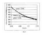
図4は、先行技術のファイバと本発明のいくつかの実施形態に係る製造されたファイバとに対する1300nmにおけるモデル化されたOFLバンド幅を示している。付加的な陥没環状リングによって、陥没環状領域を有しない比較ファイバと比較した場合、1300nmにてより高いOFLバンド幅が得られた。 FIG. 4 shows the modeled OFL bandwidth at 1300 nm for a prior art fiber and a manufactured fiber according to some embodiments of the present invention. With an additional recessed annular ring, a higher OFL bandwidth was obtained at 1300 nm when compared to a comparative fiber without a recessed annular region.
図5は、先行技術ファイバ(例5)と、本発明の種々の実施形態に係る製造された表2に示された製造されたファイバに対する波長の関数とした1×10mm曲げ損失を示している。図5に示されているように、0.6dB未満であり、より望ましくは0.4dB未満であり、さらにより望ましくは約0.3dB未満である1×10mm曲げ損失を有するファイバは、800〜1400nmに到る全バンド幅領域にわたって達成された。850nmにおいて、10mm直径のマンドレルに1回転巻きつけた際の減衰増加は、0.5dB未満であり、より望ましくは0.3dB未満であり、さらにより望ましくは0.2dB未満であり、最も望ましくは0.15dB未満である。 FIG. 5 shows the 1 × 10 mm bending loss as a function of wavelength for the prior art fiber (Example 5) and the manufactured fiber shown in Table 2 manufactured according to various embodiments of the present invention. . As shown in FIG. 5, a fiber having a 1 × 10 mm bending loss that is less than 0.6 dB, more preferably less than 0.4 dB, and even more preferably less than about 0.3 dB is 800- It was achieved over the entire bandwidth region up to 1400 nm. At 850 nm, the attenuation increase upon one turn of a 10 mm diameter mandrel is less than 0.5 dB, more preferably less than 0.3 dB, even more preferably less than 0.2 dB, most preferably It is less than 0.15 dB.
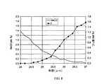
図6は、先行技術のファイバ(実施例5)と本発明の種々の実施形態に係る表2に詳しく記載され且つ製造された3つのファイバとの曲げ直径に対する1回転あたりの850nmでの減衰損失を示している。図6に示されているように、10mm直径で約0.1dB/turn以下であり、20mm直径で0.05dB/turn未満であり、30mm直径で0.01dB/turn未満である曲げ損失を示すファイバが製造された。 FIG. 6 shows the attenuation loss at 850 nm per revolution for the bending diameter of the prior art fiber (Example 5) and the three fibers detailed and manufactured in Table 2 according to various embodiments of the present invention. Is shown. As shown in FIG. 6, the bending loss is less than about 0.1 dB / turn at 10 mm diameter, less than 0.05 dB / turn at 20 mm diameter, and less than 0.01 dB / turn at 30 mm diameter. A fiber was manufactured.
実施例9及び実施例10
71.3グラムのSiO2(0.36g/ccの密度)スートが、1メートル長×26mm直径の固体ガラスコアケイン上に火炎堆積された。固体ガラスコアケインは、GeO2−SiO2グレーデッドインデックスコアガラス(純シリカに対する0.95%の最大屈折率を有し、パラボリック形状(α=2.1)である)を含む。次に、このアセンブリは以下のように焼結された。アセンブリは、最初に、1000℃にてヘリウムと3パーセントのクロリンから成る雰因気中において2時間乾燥され、それに続いて、100パーセントのヘリウム雰囲気の1500℃に設定された高温域セットを6mm/分で下方に追い出された。これは、スートを光学プリフォームに焼結せしめる目的のためであり、その光学プリフォームは、0.96のコア/クラッド(クラッド=シリカ堆積及び焼成後のケインの外径)比を有する無ボイドのGeO2−SiO2グレーディッドインデックスコア及びシリカ第1クラッド層を含む。この光学プリフォームは、20.1mmの外径を有する1メートル長のケインに線引きされた。そして、246グラムのSiO2(0.36g/ccの密度)スートが、1メートル長×20.1mm直径の固体ガラスケイン上に火炎堆積された。その固体ガラスケインは、シリカ内側クラッド層と0.96のコア/クラッド(クラッド=ケイン直径)比とを有する(純シリカに対する0.95%の最大屈折率を有し、パラボリック形状(α=2.1)である)GeO2−SiO2グレーディッドインデックスコアを含む。次に、このアセンブリは以下のように焼結された。アセンブリは、最初に、1000℃のヘリウムと3パーセントのクロリンから成る雰因気中において2時間乾燥され、それに続いて、1125℃にてヘリウムと20パーセントのSiF4からなる雰因気内でスートプリフォームが4時間フッ素ドープされ、100パーセントのヘリウム雰囲気の1480℃に設定された高温域を介して14mm/分で下方に追い出された。これは、スートをオーバークラッドプリフォームに焼結せしめる目的のためであり、かかるオーバークラッドプリフォームは酸化ゲルマニウムシリカグレーデッドインデックスコア、シリカ内側クラッド、及びフッ素ドープの第2クラッド層を含む。そして、プリフォームは、2892グラムのSiO2スートが火炎堆積された旋盤上に載置された。次に、このアセンブリは以下のように焼結された。アセンブリは、最初に、1000℃にてヘリウムと3パーセントのクロリンから成る雰因気中において2時間乾燥され、それに続いて、100パーセントのヘリウム雰囲気の1500℃に設定された高温域セットを6mm/分で下方に追い出された。これは、スートを無ボイド光学プリフォームに焼結せしめる目的のためであり、かかる無ボイド光学プリフォームは、GeO2−SiO2グレーディッドインデックスコア、シリカ第1クラッド層、フッ素ドープの第2クラッド層、及び無ボイドシリカ外部クラッドを含む。そのプリフォームは1000℃に設定され且つアルゴンでパージされた保持オーブン内にて24時間載置された。プリフォームは、約8cmの長さを有し且つ約2000℃に設定された高温域がある線引き加熱炉を使用して、10m/sで125ミクロン直径を有し8.8kmの長さを有するファイバに線引きされた。屈折率分布は、半径R1=25.4μmとΔ1MAX=0.95%の最大屈折率とを有するグレーディッドインデックスコアと、R2=26.4μmとΔ2MIN>−0.05%とΔ2MAX<0.05%とを有する内側クラッド層と、R3=31.6μmとΔ3MIN=−0.4%とV3=−121%−μm2とを有する陥没環状領域と、R4=62.5μmと0.0%の平均屈折率とを有するシリカ外部クラッドとからなることが、光ファイバの近接場測定によって確認された。Example 9 and Example 10
71.3 grams of SiO2 (0.36 g / cc density) soot was flame deposited onto a 1 meter long × 26 mm diameter solid glass core cane. The solid glass core cane comprises GeO2 —SiO2 graded index core glass (having a maximum refractive index of 0.95% with respect to pure silica and having a parabolic shape (α = 2.1)). The assembly was then sintered as follows. The assembly is first dried at 1000 ° C. in an atmosphere consisting of helium and 3 percent chlorin for 2 hours, followed by a high temperature zone set at 1500 ° C. in a 100 percent helium atmosphere at 6 mm / Driven down in minutes. This is for the purpose of sintering the soot into an optical preform, which has a core / cladding ratio of 0.96 core / cladding (cladding = outer diameter of the cane after silica deposition and firing). GeO2 —SiO2 graded index core and a silica first cladding layer. This optical preform was drawn into a 1 meter long cane having an outer diameter of 20.1 mm. 246 grams of SiO2 (0.36 g / cc density) soot was then flame deposited onto a 1 meter long × 20.1 mm diameter solid glass cane. The solid glass cane has a silica inner cladding layer and a core / cladding (cladding = cane diameter) ratio of 0.96 (having a maximum refractive index of 0.95% with respect to pure silica and a parabolic shape (α = 2 .1)) a GeO2 —SiO2 graded index core. The assembly was then sintered as follows. The assembly is first dried for 2 hours in an atmosphere consisting of 1000 ° C. helium and 3 percent chlorin, followed by soot in an atmosphere consisting of helium and 20 percent SiF4 at 1125 ° C. The preform was fluorine doped for 4 hours and driven down at 14 mm / min through a high temperature zone set at 1480 ° C. in a 100 percent helium atmosphere. This is for the purpose of sintering the soot into an overclad preform, such an overclad preform comprising a germanium oxide silica graded index core, a silica inner cladding, and a fluorine-doped second cladding layer. The preform was then placed on a lathe on which 2892 grams of SiO2 soot was flame deposited. The assembly was then sintered as follows. The assembly is first dried at 1000 ° C. in an atmosphere consisting of helium and 3 percent chlorin for 2 hours, followed by a high temperature zone set at 1500 ° C. in a 100 percent helium atmosphere at 6 mm / Driven down in minutes. This is for the purpose of sintering the soot into a void-free optical preform, such a void-free optical preform comprising a GeO2 —SiO2 graded index core, a silica first cladding layer, a fluorine-doped second cladding. And a void-free silica outer cladding. The preform was placed in a holding oven set at 1000 ° C. and purged with argon for 24 hours. The preform has a length of about 8 cm and has a 125 micron diameter at 10 m / s and a length of 8.8 km using a drawing furnace with a high temperature zone set at about 2000 ° C. The fiber was drawn. The refractive index profile consists of a graded index core having a radius R1 = 25.4 μm and a maximum refractive index of Δ1MAX = 0.95%, R2 = 26.4 μm, Δ2MIN > −0.05% and Δ2 An inner cladding layer withMAX <0.05%, a depressed annular region with R3 = 31.6 μm, Δ3MIN = −0.4% and V3 = −121% −μm2 , R4 = It was confirmed by near-field measurement of the optical fiber that it consisted of a silica outer cladding having 62.5 μm and an average refractive index of 0.0%.
表3は、本発明に係る製造された実施例9及びさらえなるファイバ(実施例10)に記載されたファイバに関して実際に測定された光物性を示す。実施例10は、注意書きを除いては、実施例9の上述した処理と同様の処理を使用して製造された。環状部30が、約0.5ミクロンより大であり且つ約4ミクロン未満であり、より望ましくは約1.0ミクロンより大であり且つ約3.0ミクロン未満であり、最も望ましくは約1.0ミクロンより大であり且つ約2.0ミクロン未満である幅W2を含むときに、高帯域幅幅及び低曲げ損失が達成され得ることを、これら実施例は示している。Table 3 shows the optical properties actually measured for the fibers described in the manufactured Example 9 and the extra fiber (Example 10) according to the present invention. Example 10 was manufactured using a process similar to that described above for Example 9 except for the notice.
表4に本発明に係る種々のモデル化されたファイバ実施例が記載されている。環状部30は、約0.5ミクロンより大であり且つ約4ミクロン未満であり、より望ましくは約1.0ミクロンより大であり且つ約3.0ミクロン未満である幅W2を含むときに、高バンド幅及び低曲げ損失が実現されることを、これら実施例は示している。1×10mmマクロベンド損失は、800〜1400nmに到る全バンド幅領域にわたって、0.6dB未満であり、より望ましくは0.4dB未満であり、さらにより望ましくは約0.3dB未満である。850nmにおいて、10mm直径のマンドレルに1回転巻きつけた際の減衰増加は、0.5dB未満であり、より望ましくは0.3dB未満であり、さらにより望ましくは0.2dB未満であり、最も望ましくは0.15dB未満である。1×15mmマクロベンド損失は、0.2dB未満であり、望ましくは0.1dB未満であり、さらにより望ましくは0.06dB未満である。Table 4 lists various modeled fiber embodiments according to the present invention.
0.14より大であり、より望ましくは0.15より大であり、さらに望ましくは0.16より大であり、最も望ましくは0.185より大である開口数を維持しつつ、中央のコアの最大屈折率を低減することによって850nm及び1300nmにおけるバンド幅を非常に高くなすことが可能であることを、表4の実施例は示している。いくつかの望ましい実施例では、開口数は0.185より大であり且つ0.215未満である。850nmでの全モード励振伝送帯域幅は、5000MHz−kmより大であり、望ましくは10000MHz−kmより大であり、より望ましくは20000MHz−kmより大であり、さらに望ましくは40000MHz−kmより大である。1300nmでの全モード励振伝送帯域幅は500MHz−kmより大であり、望ましくは700MHz−kmより大であり、より望ましくは1000MHz−kmより大である。 A central core while maintaining a numerical aperture greater than 0.14, more preferably greater than 0.15, more preferably greater than 0.16, and most preferably greater than 0.185. The example in Table 4 shows that the bandwidth at 850 nm and 1300 nm can be made very high by reducing the maximum refractive index. In some preferred embodiments, the numerical aperture is greater than 0.185 and less than 0.215. The total mode excitation transmission bandwidth at 850 nm is greater than 5000 MHz-km, desirably greater than 10000 MHz-km, more desirably greater than 20000 MHz-km, and even more desirably greater than 40000 MHz-km. . The total mode excitation transmission bandwidth at 1300 nm is greater than 500 MHz-km, desirably greater than 700 MHz-km, and more desirably greater than 1000 MHz-km.
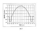
図7は、図1において上述した屈折率分布を有するファイバの内側環状部30に関して測定されたマイクロプローブの結果を示している。図7に示した実施例は、グレーディッドインデックスコアと、前記コアを包囲するクラッドと、を含むマルチモードファイバであり、クラッドは、内側環状領域と内側環状領域を囲む陥没環状領域と含む。コアは23〜26ミクロンの外側半径R1を有し、内側環状部は0.5ミクロンより大であり且つ3ミクロン未満の幅を含む。内側環状部は、0.2wtパーセントより大なる最高フッ素濃度と、0.2wtパーセントより大なる最高酸化ゲルマニウム濃度と、を含む。前記陥没環状領域は−0.2パーセント未満の屈折率デルタと、少なくとも1ミクロンの幅を有する陥没インデックスを含む。しかしながら、本発明はこのデザインに限定されないし、この実施形態への変更は、上記開示された変更のいずれをも含み得ることが理解されるべきである。図7に示されたファイバの陥没屈折率環状クラッド領域はフッ素ドープされており、かかる領域にはボイドを含んでいない。図7に示されているように、この実施形態において、この特定のファイバ内の内側環状部30は、前記内側環状部において0.3wtパーセントより大なる最高フッ素濃度と、前記内側環状部において0.3wtパーセントより大なる最高酸化ゲルマニウム濃度とを含む。前記内側環状領域は、半径が増大するにつれて、フッ素濃度が増大し且つ酸化ゲルマニウム濃度が低減する領域を含む。ファイバの酸化ゲルマニウム濃度は、25ミクロンの半径にて、望ましくは2wt%未満であり、より望ましくは1wt%未満である。前記ファイバの酸化ゲルマニウム濃度は、26.0ミクロンの半径にて、望ましくは0.5wt%未満であり、より望ましくは0.3wt%未満である。前記ファイバのフッ素濃度は、26.0ミクロンの半径にて、望ましくは2wt%未満であり、より望ましくは1.5wt%未満であり、さらにより望ましくは1wt%未満である。フッ素濃度は、26.0ミクロンの半径にて、望ましくは0.1wt%より大であり、より望ましくは0.2wt%より大であり、さらにより望ましくは0.4wt%より大である。また、前記内側環状部の中点にて、領域は0.1wtパーセントより大なるフッ素と、0.1wtパーセントより大より大なる酸化ゲルマニウムを含む。FIG. 7 shows the microprobe results measured for the inner
上記の説明は本発明の例示に過ぎず、特許請求の範囲で画定された本発明の特性と特徴の理解のための概要を与えることを目的としていることが理解されるべきである。添付図面が、本発明の更なる理解を与えるよう含まれており、本明細書の一部に組み込まれており、本明細書の一部を構成している。図面は、それら説明と共に本発明の原理と動作を説明するのに役立つ本発明の種々の特徴と実施形態とを示している。明細書に記載された本発明の好適実施形態に対する種々の変更が、添付された特許請求の範囲において画定された本発明の趣旨と範囲から逸脱しないで、なされ得ることが当業者には十分理解できるであろう。
It should be understood that the foregoing description is only illustrative of the invention and is intended to provide an overview for understanding the characteristics and features of the invention as defined in the claims. The accompanying drawings are included to provide a further understanding of the invention, and are incorporated in and constitute a part of this specification. The drawings, together with their description, illustrate various features and embodiments of the present invention that serve to explain the principles and operation of the present invention. Those skilled in the art will appreciate that various modifications to the preferred embodiments of the invention described herein can be made without departing from the spirit and scope of the invention as defined in the appended claims. It will be possible.
Claims (32)
Translated fromJapanese前記コアを囲み且つ前記コアに接触する内側クラッドと、
前記内側クラッドを囲んで約−0.2パーセント未満の屈折率デルタ及び少なくとも1ミクロンの幅を有する陥没インデックス環状部を含む第2クラッドと、を含み、
前記内側クラッドの幅は少なくとも0.5ミクロンであり且つ4ミクロン未満であることを特徴とするマルチモード光ファイバ。Graded index glass core,
An inner cladding surrounding and in contact with the core;
A second cladding including a recessed index annulus surrounding the inner cladding and having a refractive index delta of less than about -0.2 percent and a width of at least 1 micron;
A multimode optical fiber wherein the inner cladding has a width of at least 0.5 microns and less than 4 microns.
前記コアを包囲し且つ前記コアに接触する内側クラッドと、
前記内側クラッドを囲んで、前記陥没インデックス環状部は−0.2パーセント未満の屈折率デルタ及び少なくとも1ミクロンの幅を有する陥没インデックス環状部を含む第2クラッドと、を含むマルチモード光ファイバであって、
前記内側クラッドの幅は少なくとも0.5ミクロンであり、
前記ファイバは、10mm直径マンドレルに1回転巻きつけた際に、850nmにおいて0.4dB/turn以下の減衰の増加と、850nmにおいて1.5GHz−kmより大なる全モード励振伝送帯域幅と、を呈することを特徴とするマルチモード光ファイバ。Graded index glass core,
An inner cladding surrounding and in contact with the core;
Surrounding the inner cladding, the recessed index annulus is a multimode optical fiber comprising: a second cladding comprising a depressed index annulus having a refractive index delta of less than -0.2 percent and a width of at least 1 micron. And
The width of the inner cladding is at least 0.5 microns;
The fiber exhibits an attenuation increase of 0.4 dB / turn or less at 850 nm and a full mode excitation transmission bandwidth greater than 1.5 GHz-km at 850 nm when wound around a 10 mm diameter mandrel. A multimode optical fiber characterized by that.
前記コアを囲んで、内側環状領域と前記内側環状領域を囲む陥没環状領域と含みクラッドと、を含むマルチモードファイバであって、
前記コアは23〜26ミクロンの外側半径R1を有し
前記内側環状領域は、0.5ミクロンより大であり且つ3ミクロン未満の幅を有し、
前記内側環状領域は、0.2wtパーセントより大なる最高フッ素濃度と、0.2wtパーセントより大なる最高酸化ゲルマニウム濃度とをさらに有し、
前記陥没環状領域は、約−0.2パーセント未満の屈折率デルタ及び少なくとも1ミクロンの幅を有する陥没インデックスを有することを特徴とするマルチモードファイバ。Graded index core,
A multi-mode fiber including an inner annular region, a depressed annular region surrounding the inner annular region, and a clad surrounding the core;
The core has an outer radius R1 of 23-26 microns, the inner annular region has a width greater than 0.5 microns and less than 3 microns;
The inner annular region further has a maximum fluorine concentration greater than 0.2 wt percent and a maximum germanium oxide concentration greater than 0.2 wt percent;
The multimode fiber wherein the depressed annular region has a depressed index having a refractive index delta of less than about -0.2 percent and a width of at least 1 micron.
Applications Claiming Priority (5)
| Application Number | Priority Date | Filing Date | Title |
|---|---|---|---|
| US749807P | 2007-12-13 | 2007-12-13 | |
| US980308P | 2008-01-02 | 2008-01-02 | |
| US13361208P | 2008-07-01 | 2008-07-01 | |
| US12/250,987US20090169163A1 (en) | 2007-12-13 | 2008-10-14 | Bend Resistant Multimode Optical Fiber |
| PCT/US2008/013682WO2009078962A1 (en) | 2007-12-13 | 2008-12-12 | Bend resistant multimode optical fiber |
Publications (1)
| Publication Number | Publication Date |
|---|---|
| JP2011507028Atrue JP2011507028A (en) | 2011-03-03 |
Family
ID=40328663
Family Applications (1)
| Application Number | Title | Priority Date | Filing Date |
|---|---|---|---|
| JP2010537977APendingJP2011507028A (en) | 2007-12-13 | 2008-12-12 | Bending resistant multimode optical fiber |
Country Status (6)
| Country | Link |
|---|---|
| US (2) | US20090169163A1 (en) |
| EP (1) | EP2220524B1 (en) |
| JP (1) | JP2011507028A (en) |
| KR (1) | KR20100098691A (en) |
| CN (1) | CN101932961B (en) |
| WO (1) | WO2009078962A1 (en) |
Cited By (10)
| Publication number | Priority date | Publication date | Assignee | Title |
|---|---|---|---|---|
| JP2011059687A (en)* | 2009-09-09 | 2011-03-24 | Draka Comteq Bv | Multimode optical fiber having improved bending loss |
| JP2011118396A (en)* | 2009-12-03 | 2011-06-16 | Draka Comteq Bv | Low bending loss multi-mode optical fiber reduced in clad effect |
| JP2012203416A (en)* | 2011-03-24 | 2012-10-22 | Draka Comteq Bv | Multimode optical fiber with improved bend resistance |
| JP2012208497A (en)* | 2011-03-29 | 2012-10-25 | Draka Comteq Bv | Multimode optical fiber |
| JP2013047785A (en)* | 2011-07-01 | 2013-03-07 | Draka Comteq Bv | Multimode optical fiber |
| JP2013521532A (en)* | 2010-03-02 | 2013-06-10 | コーニング インコーポレイテッド | Large numerical aperture multimode optical fiber |
| JP2013200544A (en)* | 2012-03-23 | 2013-10-03 | Draka Comteq Bv | Bend-resistant multimode optical fiber |
| JP2013235264A (en)* | 2012-05-08 | 2013-11-21 | Sumitomo Electric Ind Ltd | Multimode optical fiber |
| JP2015521300A (en)* | 2012-05-31 | 2015-07-27 | コーニング インコーポレイテッド | Multimode optical fiber and system including the fiber |
| JP2016099623A (en)* | 2014-11-25 | 2016-05-30 | 長飛光繊光纜股▲ふん▼有限公司 | Bend-insensitive multimode optical fiber |
Families Citing this family (272)
| Publication number | Priority date | Publication date | Assignee | Title |
|---|---|---|---|---|
| NL1024015C2 (en) | 2003-07-28 | 2005-02-01 | Draka Fibre Technology Bv | Multimode optical fiber provided with a refractive index profile, optical communication system using this and method for manufacturing such a fiber. |
| US9652708B2 (en) | 2006-10-31 | 2017-05-16 | Fiber Mountain, Inc. | Protocol for communications between a radio frequency identification (RFID) tag and a connected device, and related systems and methods |
| US9652709B2 (en) | 2006-10-31 | 2017-05-16 | Fiber Mountain, Inc. | Communications between multiple radio frequency identification (RFID) connected tags and one or more devices, and related systems and methods |
| US9652707B2 (en) | 2006-10-31 | 2017-05-16 | Fiber Mountain, Inc. | Radio frequency identification (RFID) connected tag communications protocol and related systems and methods |
| US8107784B2 (en)* | 2007-06-15 | 2012-01-31 | Ofs Fitel, Llc | Reduced bend sensitivity and catastrophic bend loss in single mode optical fibers and method of making same |
| FR2922657B1 (en) | 2007-10-23 | 2010-02-12 | Draka Comteq France | MULTIMODE FIBER. |
| DK2206001T3 (en) | 2007-11-09 | 2014-07-07 | Draka Comteq Bv | Optical fiber resistant to microbending |
| US8041168B2 (en) | 2007-11-09 | 2011-10-18 | Draka Comteq, B.V. | Reduced-diameter ribbon cables with high-performance optical fiber |
| US8031997B2 (en) | 2007-11-09 | 2011-10-04 | Draka Comteq, B.V. | Reduced-diameter, easy-access loose tube cable |
| US8081853B2 (en) | 2007-11-09 | 2011-12-20 | Draka Comteq, B.V. | Single-fiber drop cables for MDU deployments |
| US8041167B2 (en)* | 2007-11-09 | 2011-10-18 | Draka Comteq, B.V. | Optical-fiber loose tube cables |
| US8165439B2 (en)* | 2007-11-09 | 2012-04-24 | Draka Comteq, B.V. | ADSS cables with high-performance optical fiber |
| US8145026B2 (en) | 2007-11-09 | 2012-03-27 | Draka Comteq, B.V. | Reduced-size flat drop cable |
| US8467650B2 (en)* | 2007-11-09 | 2013-06-18 | Draka Comteq, B.V. | High-fiber-density optical-fiber cable |
| US7947945B2 (en)* | 2008-02-29 | 2011-05-24 | Corning Incorporated | Fiber optic sensing system, method of using such and sensor fiber |
| FR2930997B1 (en) | 2008-05-06 | 2010-08-13 | Draka Comteq France Sa | OPTICAL FIBER MONOMODE |
| FR2932932B1 (en)* | 2008-06-23 | 2010-08-13 | Draka Comteq France Sa | MULTIPLEX WAVE LENGTH OPTIC SYSTEM WITH MULTIMODE OPTIC FIBERS |
| FR2933779B1 (en)* | 2008-07-08 | 2010-08-27 | Draka Comteq France | MULTIMODE OPTIC FIBERS |
| US11294136B2 (en) | 2008-08-29 | 2022-04-05 | Corning Optical Communications LLC | High density and bandwidth fiber optic apparatuses and related equipment and methods |
| US8452148B2 (en) | 2008-08-29 | 2013-05-28 | Corning Cable Systems Llc | Independently translatable modules and fiber optic equipment trays in fiber optic equipment |
| US8520994B2 (en)* | 2008-09-17 | 2013-08-27 | Ofs Fitel, Llc | Bandwidth-maintaining multimode optical fibers |
| US9568669B2 (en)* | 2008-09-17 | 2017-02-14 | Ofs Fitel, Llc | Bandwidth-maintaining multimode optical fibers |
| US9207421B2 (en)* | 2008-10-14 | 2015-12-08 | Corning Cable Systems Llc | Fiber optic network architecture having optical connection terminals in series arrangement |
| US8873967B2 (en)* | 2008-10-17 | 2014-10-28 | Corning Cable Systems Llc | Optical interconnection modules for hybrid electrical-optical networks |
| PL2344911T3 (en) | 2008-11-07 | 2015-10-30 | Draka Comteq Bv | Reduced-diameter optical fiber |
| FR2940839B1 (en) | 2009-01-08 | 2012-09-14 | Draka Comteq France | INDEX GRADIENT MULTIMODAL OPTICAL FIBER, METHODS FOR CHARACTERIZATION AND MANUFACTURE OF SUCH A FIBER |
| FR2941539B1 (en)* | 2009-01-23 | 2011-02-25 | Draka Comteq France | OPTICAL FIBER MONOMODE |
| US9673904B2 (en) | 2009-02-03 | 2017-06-06 | Corning Optical Communications LLC | Optical fiber-based distributed antenna systems, components, and related methods for calibration thereof |
| CN102396171B (en) | 2009-02-03 | 2015-09-30 | 康宁光缆系统有限责任公司 | Based on the distributing antenna system of optical fiber, assembly and the correlation technique for monitoring and configure distributing antenna system based on optical fiber, assembly |
| CN102369678B (en) | 2009-02-03 | 2015-08-19 | 康宁光缆系统有限责任公司 | Optical fiber based distributed antenna systems, assemblies and related methods for calibrating optical fiber based distributed antenna systems, assemblies |
| EP2221932B1 (en) | 2009-02-24 | 2011-11-16 | CCS Technology Inc. | Holding device for a cable or an assembly for use with a cable |
| US8013985B2 (en)* | 2009-03-30 | 2011-09-06 | Corning Incorporated | Methods of measuring the refractive index profile of a transparent cylindrical object |
| US8699838B2 (en) | 2009-05-14 | 2014-04-15 | Ccs Technology, Inc. | Fiber optic furcation module |
| US8538226B2 (en) | 2009-05-21 | 2013-09-17 | Corning Cable Systems Llc | Fiber optic equipment guides and rails configured with stopping position(s), and related equipment and methods |
| US9075216B2 (en) | 2009-05-21 | 2015-07-07 | Corning Cable Systems Llc | Fiber optic housings configured to accommodate fiber optic modules/cassettes and fiber optic panels, and related components and methods |
| US9482840B2 (en)* | 2009-05-27 | 2016-11-01 | Corning Cable Systems Llc | Port mapping for series connected fiber optic terminals |
| FR2946436B1 (en) | 2009-06-05 | 2011-12-09 | Draka Comteq France | MULTIMODE OPTICAL FIBER WITH LARGE BANDWIDTH WITH AN OPTIMIZED HEAT-SLEEVE INTERFACE |
| US8251591B2 (en) | 2009-06-17 | 2012-08-28 | Corning Cable Systems | Optical interconnection assemblies and systems for high-speed data-rate optical transport systems |
| EP2443497B1 (en) | 2009-06-19 | 2020-03-04 | Corning Cable Systems LLC | High density and bandwidth fiber optic apparatus |
| WO2010148325A1 (en) | 2009-06-19 | 2010-12-23 | Corning Cable Systems Llc | High fiber optic cable packing density apparatus |
| US8712206B2 (en) | 2009-06-19 | 2014-04-29 | Corning Cable Systems Llc | High-density fiber optic modules and module housings and related equipment |
| US8548330B2 (en) | 2009-07-31 | 2013-10-01 | Corning Cable Systems Llc | Sectorization in distributed antenna systems, and related components and methods |
| FR2953030B1 (en)* | 2009-11-25 | 2011-11-18 | Draka Comteq France | MULTIMODE OPTICAL FIBER WITH LARGE BANDWIDTH WITH AN OPTIMIZED HEAT-SLEEVE INTERFACE |
| FR2957153B1 (en)* | 2010-03-02 | 2012-08-10 | Draka Comteq France | MULTIMODE OPTICAL FIBER WITH BROAD BANDWIDTH AND LOW BENDBACK LOSSES |
| FR2953029B1 (en) | 2009-11-25 | 2011-11-18 | Draka Comteq France | MULTIMODE OPTICAL FIBER WITH LARGE BANDWIDTH WITH AN OPTIMIZED HEAT-SLEEVE INTERFACE |
| US9014525B2 (en) | 2009-09-09 | 2015-04-21 | Draka Comteq, B.V. | Trench-assisted multimode optical fiber |
| FR2953606B1 (en)* | 2009-12-03 | 2012-04-27 | Draka Comteq France | MULTIMODE OPTICAL FIBER WITH BROAD BANDWIDTH AND LOW BENDBACK LOSSES |
| FR2950156B1 (en)* | 2009-09-17 | 2011-11-18 | Draka Comteq France | MULTIMODE OPTIC FIBER |
| US8335417B2 (en) | 2009-09-30 | 2012-12-18 | Corning Cable Systems Llc | Crush-resistant fiber optic cables employing bend-resistant multimode fibers |
| US8805143B2 (en)* | 2009-10-19 | 2014-08-12 | Draka Comteq, B.V. | Optical-fiber cable having high fiber count and high fiber density |
| US8428407B2 (en)* | 2009-10-21 | 2013-04-23 | Corning Cable Systems Llc | Fiber optic jumper cable with bend-resistant multimode fiber |
| US8488929B2 (en)* | 2009-11-09 | 2013-07-16 | Corning Cable Systems Llc | Tactical cable |
| US8280259B2 (en) | 2009-11-13 | 2012-10-02 | Corning Cable Systems Llc | Radio-over-fiber (RoF) system for protocol-independent wired and/or wireless communication |
| US8625950B2 (en) | 2009-12-18 | 2014-01-07 | Corning Cable Systems Llc | Rotary locking apparatus for fiber optic equipment trays and related methods |
| CN101738681B (en)* | 2010-01-20 | 2011-08-31 | 长飞光纤光缆有限公司 | High bandwidth multimode fiber |
| JP2013518310A (en) | 2010-01-26 | 2013-05-20 | コーニング インコーポレイテッド | Optical fiber |
| US8306382B2 (en) | 2010-02-01 | 2012-11-06 | Corning Cable Systems Llc | Methods, cleavers, and packagings for cleaving an optical fiber using an abrasive medium |
| US8992099B2 (en) | 2010-02-04 | 2015-03-31 | Corning Cable Systems Llc | Optical interface cards, assemblies, and related methods, suited for installation and use in antenna system equipment |
| EP2534511B1 (en)* | 2010-02-09 | 2024-10-30 | OFS Fitel, LLC | Improvement of dmd performance in bend optimized multimode fiber |
| US8275265B2 (en) | 2010-02-15 | 2012-09-25 | Corning Cable Systems Llc | Dynamic cell bonding (DCB) for radio-over-fiber (RoF)-based networks and communication systems and related methods |
| US7865050B1 (en) | 2010-02-16 | 2011-01-04 | Ofs Fitel, Llc | Equalizing modal delay of high order modes in bend insensitive multimode fiber |
| US7903918B1 (en) | 2010-02-22 | 2011-03-08 | Corning Incorporated | Large numerical aperture bend resistant multimode optical fiber |
| US8678260B2 (en) | 2010-02-23 | 2014-03-25 | Corning Cable Systems Llc | Bladeless cleavers having an arcuate exterior surface and related methods for cleaving an optical fiber using an abrasive medium |
| WO2011112763A1 (en) | 2010-03-10 | 2011-09-15 | Corning Cable Systems Llc | Fiber optic cassette |
| AU2011224314A1 (en) | 2010-03-10 | 2012-09-06 | Corning Cable Systems Llc | Fiber optic pigtail assembly allowing single and mass splicing |
| ES2539824T3 (en)* | 2010-03-17 | 2015-07-06 | Draka Comteq B.V. | Single mode fiber optic with reduced curvature losses |
| US8913866B2 (en) | 2010-03-26 | 2014-12-16 | Corning Cable Systems Llc | Movable adapter panel |
| WO2011123336A1 (en) | 2010-03-31 | 2011-10-06 | Corning Cable Systems Llc | Localization services in optical fiber-based distributed communications components and systems, and related methods |
| US9097873B2 (en) | 2010-04-14 | 2015-08-04 | Corning Cable Systems Llc | Port mapping in fiber optic network devices |
| CA2796221C (en) | 2010-04-16 | 2018-02-13 | Ccs Technology, Inc. | Sealing and strain relief device for data cables |
| EP2381284B1 (en) | 2010-04-23 | 2014-12-31 | CCS Technology Inc. | Under floor fiber optic distribution device |
| US8879881B2 (en) | 2010-04-30 | 2014-11-04 | Corning Cable Systems Llc | Rotatable routing guide and assembly |
| EP2564251B1 (en) | 2010-04-30 | 2017-06-07 | Corning Optical Communications LLC | Fiber optic housings with removable panel clips |
| US20110268408A1 (en) | 2010-04-30 | 2011-11-03 | Giraud William J | Door fiber management for fiber optic housings, and related components and methods |
| US9720195B2 (en) | 2010-04-30 | 2017-08-01 | Corning Optical Communications LLC | Apparatuses and related components and methods for attachment and release of fiber optic housings to and from an equipment rack |
| US9519118B2 (en) | 2010-04-30 | 2016-12-13 | Corning Optical Communications LLC | Removable fiber management sections for fiber optic housings, and related components and methods |
| US8705926B2 (en) | 2010-04-30 | 2014-04-22 | Corning Optical Communications LLC | Fiber optic housings having a removable top, and related components and methods |
| US20110268405A1 (en) | 2010-04-30 | 2011-11-03 | Cote Monique L | Stackable shelves for a fiber optic housing, and related components and methods |
| US8660397B2 (en) | 2010-04-30 | 2014-02-25 | Corning Cable Systems Llc | Multi-layer module |
| US9075217B2 (en) | 2010-04-30 | 2015-07-07 | Corning Cable Systems Llc | Apparatuses and related components and methods for expanding capacity of fiber optic housings |
| US9632270B2 (en) | 2010-04-30 | 2017-04-25 | Corning Optical Communications LLC | Fiber optic housings configured for tool-less assembly, and related components and methods |
| US20110268446A1 (en) | 2010-05-02 | 2011-11-03 | Cune William P | Providing digital data services in optical fiber-based distributed radio frequency (rf) communications systems, and related components and methods |
| WO2011139939A1 (en) | 2010-05-02 | 2011-11-10 | Corning Cable Systems Llc | Optical fiber-based distributed communications systems, and related components and methods |
| WO2011139942A1 (en) | 2010-05-02 | 2011-11-10 | Corning Cable Systems Llc | Providing digital data services in optical fiber -based distributed radio frequency (rf) communications system |
| WO2011139937A1 (en) | 2010-05-02 | 2011-11-10 | Corning Cable Systems Llc | Digital data services and/or power distribution in optical fiber-based distributed communications systems providing digital data and radio frequency (rf) communications services, and related components and methods |
| US9525488B2 (en) | 2010-05-02 | 2016-12-20 | Corning Optical Communications LLC | Digital data services and/or power distribution in optical fiber-based distributed communications systems providing digital data and radio frequency (RF) communications services, and related components and methods |
| US20110274402A1 (en) | 2010-05-07 | 2011-11-10 | Giraud William J | Removable fiber management devices for fiber optic housings, and related components and methods |
| CN203251299U (en) | 2010-06-04 | 2013-10-23 | Ccs技术股份有限公司 | Distributed Communication System Based on Optical Fiber |
| US8410909B2 (en) | 2010-07-09 | 2013-04-02 | Corning Incorporated | Cables and connector assemblies employing a furcation tube(s) for radio-frequency identification (RFID)-equipped connectors, and related systems and methods |
| US8570914B2 (en) | 2010-08-09 | 2013-10-29 | Corning Cable Systems Llc | Apparatuses, systems, and methods for determining location of a mobile device(s) in a distributed antenna system(s) |
| DK2418523T3 (en) | 2010-08-12 | 2017-01-09 | Draka Comteq Bv | A multimode optical fiber having immersed gradientindeks |
| NL2005220C2 (en)* | 2010-08-12 | 2012-02-14 | Draka Comteq Bv | Depressed graded index multi-mode optical fiber. |
| WO2012024247A1 (en) | 2010-08-16 | 2012-02-23 | Corning Cable Systems Llc | Remote antenna clusters and related systems, components, and methods supporting digital data signal propagation between remote antenna units |
| US8718436B2 (en) | 2010-08-30 | 2014-05-06 | Corning Cable Systems Llc | Methods, apparatuses for providing secure fiber optic connections |
| US9160449B2 (en) | 2010-10-13 | 2015-10-13 | Ccs Technology, Inc. | Local power management for remote antenna units in distributed antenna systems |
| US9252874B2 (en) | 2010-10-13 | 2016-02-02 | Ccs Technology, Inc | Power management for remote antenna units in distributed antenna systems |
| CN103329482B (en) | 2010-10-13 | 2016-04-13 | Ccs技术股份有限公司 | For electrical management device and the method for distributing antenna system medium-long range antenna element |
| CN103329481B (en) | 2010-10-13 | 2016-09-07 | Ccs技术股份有限公司 | Local power management for remote antenna units in distributed antenna systems |
| FR2966255A1 (en)* | 2010-10-18 | 2012-04-20 | Draka Comteq France | Multimode optical fibers selection method for transmission system, involves selecting fibers, where modal bandwidth and value of bandwidth are function of predetermined bending loss |
| FR2966256B1 (en)* | 2010-10-18 | 2012-11-16 | Draka Comteq France | MULTIMODE OPTICAL FIBER INSENSITIVE TO LOSSES BY |
| WO2012054454A2 (en) | 2010-10-19 | 2012-04-26 | Corning Cable Systems Llc | Transition box for multiple dwelling unit fiber optic distribution network |
| US9279951B2 (en) | 2010-10-27 | 2016-03-08 | Corning Cable Systems Llc | Fiber optic module for limited space applications having a partially sealed module sub-assembly |
| WO2012058391A1 (en) | 2010-10-28 | 2012-05-03 | Corning Cable Systems Llc | Impact resistant fiber optic enclosures and related methods |
| US9116324B2 (en) | 2010-10-29 | 2015-08-25 | Corning Cable Systems Llc | Stacked fiber optic modules and fiber optic equipment configured to support stacked fiber optic modules |
| US8662760B2 (en) | 2010-10-29 | 2014-03-04 | Corning Cable Systems Llc | Fiber optic connector employing optical fiber guide member |
| WO2012064333A1 (en) | 2010-11-12 | 2012-05-18 | Ccs Technology, Inc. | Providing digital data services using electrical power line(s) in optical fiber-based distributed radio frequency (rf) communications systems, and related components and methods |
| WO2012071364A1 (en) | 2010-11-23 | 2012-05-31 | Corning Cable Systems Llc | Imbedded carrier blades for cleaving optical fibers, and related cleavers and methods |
| WO2012071363A1 (en) | 2010-11-23 | 2012-05-31 | Corning Cable Systems Llc | Cleavers for cleaving optical fibers, and related blades, components, and methods |
| EP2643947B1 (en) | 2010-11-24 | 2018-09-19 | Corning Optical Communications LLC | Power distribution module(s) capable of hot connection and/or disconnection for distributed antenna systems, and related power units, components, and methods |
| US11296504B2 (en) | 2010-11-24 | 2022-04-05 | Corning Optical Communications LLC | Power distribution module(s) capable of hot connection and/or disconnection for wireless communication systems, and related power units, components, and methods |
| CA2819235C (en) | 2010-11-30 | 2018-01-16 | Corning Cable Systems Llc | Fiber device holder and strain relief device |
| US9481599B2 (en)* | 2010-12-21 | 2016-11-01 | Corning Incorporated | Method of making a multimode optical fiber |
| CN102043197A (en)* | 2011-01-26 | 2011-05-04 | 长飞光纤光缆有限公司 | Bend-resistance multimode optical fiber |
| EP2482106B1 (en) | 2011-01-31 | 2014-06-04 | Draka Comteq B.V. | Multimode fiber |
| FR2971061B1 (en)* | 2011-01-31 | 2013-02-08 | Draka Comteq France | BROAD BANDWIDTH OPTICAL FIBER WITH LOW CURB LOSSES |
| WO2012106510A2 (en) | 2011-02-02 | 2012-08-09 | Corning Cable Systems Llc | Dense fiber optic connector assemblies and related connectors and cables suitable for establishing optical connections for optical backplanes in equipment racks |
| EP2678972B1 (en) | 2011-02-21 | 2018-09-05 | Corning Optical Communications LLC | Providing digital data services as electrical signals and radio-frequency (rf) communications over optical fiber in distributed communications systems, and related components and methods |
| EP2681600A1 (en) | 2011-02-28 | 2014-01-08 | Corning Cable Systems LLC | Mounting devices for optical devices, and related sub- assemblies, apparatuses, and methods |
| US8792763B2 (en) | 2011-03-07 | 2014-07-29 | Corning Incorporated | Bend resistant multimode optical fiber |
| EP2518546B1 (en) | 2011-04-27 | 2018-06-20 | Draka Comteq B.V. | High-bandwidth, radiation-resistant multimode optical fiber |
| WO2012148938A1 (en) | 2011-04-29 | 2012-11-01 | Corning Cable Systems Llc | Determining propagation delay of communications in distributed antenna systems, and related components, systems and methods |
| WO2012148940A1 (en) | 2011-04-29 | 2012-11-01 | Corning Cable Systems Llc | Systems, methods, and devices for increasing radio frequency (rf) power in distributed antenna systems |
| US9008485B2 (en) | 2011-05-09 | 2015-04-14 | Corning Cable Systems Llc | Attachment mechanisms employed to attach a rear housing section to a fiber optic housing, and related assemblies and methods |
| DE102011109838A1 (en)* | 2011-05-27 | 2012-11-29 | J-Plasma Gmbh | optical fiber |
| US8953916B2 (en) | 2011-06-22 | 2015-02-10 | Corning Cable Systems Llc | Multi-fiber, fiber optic cable assemblies providing constrained optical fibers within an optical fiber sub-unit, and related fiber optic components, cables, and methods |
| CN102193142B (en) | 2011-06-28 | 2013-06-26 | 长飞光纤光缆有限公司 | A bending-resistant large core diameter high numerical aperture multimode optical fiber |
| AU2012275598A1 (en) | 2011-06-30 | 2014-01-16 | Corning Optical Communications LLC | Fiber optic equipment assemblies employing non-U-width-sized housings and related methods |
| US9873629B2 (en) | 2011-06-30 | 2018-01-23 | Corning Incorporated | Methods for producing optical fiber preforms with low index trenches |
| US8842957B2 (en) | 2011-06-30 | 2014-09-23 | Corning Incorporated | Multimode optical fiber and system incorporating such |
| WO2013003195A1 (en) | 2011-06-30 | 2013-01-03 | Corning Cable Systems Llc | Multi-port optical connection terminal assemblies supporting optical signal splitting, and related terminals and methods |
| EP2730038A1 (en) | 2011-07-08 | 2014-05-14 | Corning Cable Systems LLC | Optical fiber-based distributed radio frequency (rf) antenna systems supporting multiple-input, multiple-output (mimo) configurations, and related components and methods |
| US8630523B2 (en) | 2011-07-13 | 2014-01-14 | Corning Cable Systems Llc | Methods of preparing strength member pulling members in fiber optic cable furcations and related components, assemblies, and fiber optic cables |
| US8540435B2 (en) | 2011-07-22 | 2013-09-24 | Corning Cable Systems Llc | Ferrule retainers having access window(s) for accessing and/or referencing a fiber optic ferrule, and related fiber optic connector assemblies, connectors, and referencing methods |
| US9110266B2 (en) | 2011-07-29 | 2015-08-18 | Corning Cable Systems Llc | Fiber optic cables seal and/or strain relief members, and related assemblies and methods |
| US8666213B2 (en) | 2011-08-22 | 2014-03-04 | Corning Incorporated | Method of making multimode optical fibers |
| US8953924B2 (en) | 2011-09-02 | 2015-02-10 | Corning Cable Systems Llc | Removable strain relief brackets for securing fiber optic cables and/or optical fibers to fiber optic equipment, and related assemblies and methods |
| CN103797391B (en) | 2011-09-13 | 2016-09-28 | 康宁光电通信有限责任公司 | Translating lens holder assembly using drilled nesting area and optical connector incorporating said lens holder assembly |
| US20130084048A1 (en)* | 2011-09-29 | 2013-04-04 | Sumitomo Electric Industries, Ltd. | Multi-mode optical fiber |
| US8565566B2 (en) | 2011-10-05 | 2013-10-22 | Sumitomo Electric Industries, Ltd. | Multi-mode optical fiber |
| CN103874949B (en) | 2011-10-11 | 2017-08-25 | 康宁光电通信有限责任公司 | Suppress fiber optic cables boundary of the optical fiber relative to the movement of strength member and related assembly and method |
| US9069151B2 (en) | 2011-10-26 | 2015-06-30 | Corning Cable Systems Llc | Composite cable breakout assembly |
| US8965163B2 (en) | 2011-11-04 | 2015-02-24 | Corning Incorporated | Ge-P co-doped multimode optical fiber |
| US8588568B2 (en) | 2011-11-04 | 2013-11-19 | Corning Incorporated | Bend loss resistant multi-mode fiber |
| US8565567B2 (en) | 2011-11-23 | 2013-10-22 | Sumitomo Electric Industries, Ltd. | Multi-mode optical fiber |
| US9038832B2 (en) | 2011-11-30 | 2015-05-26 | Corning Cable Systems Llc | Adapter panel support assembly |
| EP2788806A2 (en) | 2011-12-09 | 2014-10-15 | Corning Optical Communications LLC | Gradient index (grin) lens holders employing groove alignment feature(s) and total internal reflection (tir) surface, and related components, connectors, and methods |
| WO2013086117A2 (en) | 2011-12-09 | 2013-06-13 | Corning Cable Systems Llc | Gradient index (grin) lens holders employing groove alignment features(s) in recessed cover and single piece components, connectors, and methods |
| US9219546B2 (en) | 2011-12-12 | 2015-12-22 | Corning Optical Communications LLC | Extremely high frequency (EHF) distributed antenna systems, and related components and methods |
| WO2013089665A1 (en) | 2011-12-12 | 2013-06-20 | Corning Cable Systems Llc | Extremely high frequency (ehf) distributed antenna systems, and related components and methods |
| US9103994B2 (en) | 2012-01-31 | 2015-08-11 | Corning Cable Systems Llc | Optical fiber guide apparatuses for splice connector installation tools, and related assemblies and methods |
| US20130195415A1 (en) | 2012-01-31 | 2013-08-01 | Brandon A. Barnes | Detachable optical fiber guides for splice connector installation tools, and related assemblies and methods |
| EP2810449B1 (en) | 2012-02-01 | 2018-10-03 | Corning Incorporated | Radio frequency identification (rfid) connected tag communications protocol and related systems and methods |
| WO2013116417A1 (en) | 2012-02-01 | 2013-08-08 | Corning Incorporated | Protocol for communications between a radio frequency identification (rfid) tag and a connected device, and related systems and methods |
| IN2014DN06566A (en) | 2012-02-01 | 2015-05-22 | Corning Inc | |
| JP5887999B2 (en)* | 2012-02-28 | 2016-03-16 | 住友電気工業株式会社 | Optical fiber |
| US10110307B2 (en) | 2012-03-02 | 2018-10-23 | Corning Optical Communications LLC | Optical network units (ONUs) for high bandwidth connectivity, and related components and methods |
| US9759860B2 (en)* | 2012-03-05 | 2017-09-12 | Alcatel Lucent | Multimode optical fiber, mode delay adjuster for fiber systems, and methods to use such fibers, adjusters, and systems |
| US9052478B2 (en) | 2012-03-30 | 2015-06-09 | Corning Cable Systems Llc | Total-internal-reflection fiber optic interface modules with different optical paths and assemblies using same |
| US8913858B2 (en) | 2012-03-30 | 2014-12-16 | Corning Cable Systems Llc | Total-internal-reflection fiber optic interface modules and assemblies |
| EP2832012A1 (en) | 2012-03-30 | 2015-02-04 | Corning Optical Communications LLC | Reducing location-dependent interference in distributed antenna systems operating in multiple-input, multiple-output (mimo) configuration, and related components, systems, and methods |
| US9435963B2 (en)* | 2012-03-30 | 2016-09-06 | Corning Cable Systems Llc | Misalignment-tolerant total-internal-reflection fiber optic interface modules and assemblies with high coupling efficiency |
| WO2013162988A1 (en) | 2012-04-25 | 2013-10-31 | Corning Cable Systems Llc | Distributed antenna system architectures |
| US8873926B2 (en) | 2012-04-26 | 2014-10-28 | Corning Cable Systems Llc | Fiber optic enclosures employing clamping assemblies for strain relief of cables, and related assemblies and methods |
| US20130287342A1 (en) | 2012-04-30 | 2013-10-31 | Paulo Clóvis Dainese Júnior | Lead-in formations in optical fiber segments and methods of forming lead-in formations |
| US9165232B2 (en) | 2012-05-14 | 2015-10-20 | Corning Incorporated | Radio-frequency identification (RFID) tag-to-tag autoconnect discovery, and related methods, circuits, and systems |
| US20130308916A1 (en) | 2012-05-16 | 2013-11-21 | Scott Eaker Buff | High-density port tap fiber optic modules, and related systems and methods for monitoring optical networks |
| CN102692675A (en)* | 2012-05-28 | 2012-09-26 | 长飞光纤光缆有限公司 | Gradual refractive index bending resistant multimode optical fiber |
| US8837890B2 (en) | 2012-05-31 | 2014-09-16 | Corning Incorporated | Multimode optical fiber and system comprising such fiber |
| US9057815B2 (en) | 2012-05-31 | 2015-06-16 | Corning Cable Systems Llc | Angular alignment of optical fibers for fiber optic ribbon cables, and related methods |
| US8858090B2 (en) | 2012-06-05 | 2014-10-14 | Corning Cable Systems Llc | Ferrule holders with an integral lead-in tube employed in fiber optic connector assemblies, and related components, connectors, and methods |
| US20130343709A1 (en) | 2012-06-22 | 2013-12-26 | Jeffrey Dean Danley | Ferrule assemblies employing mechanical interfaces for optical fibers, and related components and methods |
| US9250409B2 (en) | 2012-07-02 | 2016-02-02 | Corning Cable Systems Llc | Fiber-optic-module trays and drawers for fiber-optic equipment |
| US9097874B2 (en) | 2012-07-25 | 2015-08-04 | Corning Optical Communications LLC | Polarity configurations for parallel optics data transmission, and related apparatuses, components, systems, and methods |
| US9057863B2 (en) | 2012-07-25 | 2015-06-16 | Corning Cable Systems Llc | Polarity scheme for parallel-optics data transmission |
| US9304265B2 (en) | 2012-07-26 | 2016-04-05 | Corning Cable Systems Llc | Fiber optic connectors employing moveable optical interfaces with fiber protection features and related components and methods |
| US9154222B2 (en) | 2012-07-31 | 2015-10-06 | Corning Optical Communications LLC | Cooling system control in distributed antenna systems |
| WO2014024192A1 (en) | 2012-08-07 | 2014-02-13 | Corning Mobile Access Ltd. | Distribution of time-division multiplexed (tdm) management services in a distributed antenna system, and related components, systems, and methods |
| US9366810B2 (en) | 2012-08-29 | 2016-06-14 | Ofs Fitel, Llc | Double-clad, gain-producing fibers with increased cladding absoroption while maintaining single-mode operation |
| US9417406B2 (en) | 2012-08-31 | 2016-08-16 | Corning Cable Systems Llc | Cable assemblies and optical connector assemblies employing a unitary alignment pin and translating element |
| US10139573B2 (en) | 2012-08-31 | 2018-11-27 | Corning Optical Communications LLC | Cable assemblies, optical connector assemblies, and optical connector subassemblies employing a unitary alignment pin and cover |
| US9529162B2 (en) | 2012-10-09 | 2016-12-27 | Corning Optical Communications LLC | Optical fiber connectors and methods of forming optical fiber connectors |
| DE102013200165B4 (en) | 2012-10-12 | 2019-09-19 | J-Fiber Gmbh | Optical fiber in the form of a bending-resistant multimode fiber and its use |
| ES2551077T3 (en) | 2012-10-26 | 2015-11-16 | Ccs Technology, Inc. | Fiber optic management unit and fiber optic distribution device |
| EP2725396B1 (en) | 2012-10-26 | 2016-09-14 | CCS Technology, Inc. | Strain relief device for cables and fiber optic distribution device |
| US9455784B2 (en) | 2012-10-31 | 2016-09-27 | Corning Optical Communications Wireless Ltd | Deployable wireless infrastructures and methods of deploying wireless infrastructures |
| US8917968B2 (en) | 2012-11-06 | 2014-12-23 | Corning Optical Communications LLC | Furcation plugs having segregated channels to guide epoxy into passageways for optical fiber furcation, and related assemblies and methods |
| US10257056B2 (en) | 2012-11-28 | 2019-04-09 | Corning Optical Communications LLC | Power management for distributed communication systems, and related components, systems, and methods |
| US9529155B2 (en) | 2012-11-28 | 2016-12-27 | Corning Optical Communications LLC | Gradient index (GRIN) lens chips and associated small form factor optical arrays for optical connections, related fiber optic connectors |
| US9647758B2 (en) | 2012-11-30 | 2017-05-09 | Corning Optical Communications Wireless Ltd | Cabling connectivity monitoring and verification |
| WO2014089010A1 (en) | 2012-12-06 | 2014-06-12 | Corning Incorporated | Opto-electrical connection systems including opto-electrical cables providing configurable connectivity between electrical devices having electrical interfaces, and related assemblies and methods |
| US9497706B2 (en) | 2013-02-20 | 2016-11-15 | Corning Optical Communications Wireless Ltd | Power management in distributed antenna systems (DASs), and related components, systems, and methods |
| US9020316B2 (en) | 2013-02-28 | 2015-04-28 | Corning Incorporated | Low attenuation optical fibers with an F-graded index core |
| US8985862B2 (en) | 2013-02-28 | 2015-03-24 | Corning Cable Systems Llc | High-density multi-fiber adapter housings |
| US8950949B2 (en) | 2013-03-14 | 2015-02-10 | Corning Cable Systems Llc | Circuit board(s) employing optical interfaces optically connected to surface-accessible, planar-shaped, inter-board optical fiber traces, and related connectors, assemblies, and methods |
| US9052469B2 (en) | 2013-04-26 | 2015-06-09 | Corning Cable Systems Llc | Preterminated fiber optic connector sub-assemblies, and related fiber optic connectors, cable assemblies, and methods |
| US8755654B1 (en) | 2013-05-10 | 2014-06-17 | Corning Cable Systems Llc | Coating removal systems for optical fibers |
| US9085047B2 (en) | 2013-05-10 | 2015-07-21 | Corning Optical Communications LLC | Coating removal systems for optical fibers |
| EP3152539A4 (en) | 2013-06-08 | 2018-02-21 | Université Laval | Fiber-optic thermometer |
| WO2014199380A1 (en) | 2013-06-12 | 2014-12-18 | Corning Optical Communications Wireless, Ltd. | Time-division duplexing (tdd) in distributed communications systems, including distributed antenna systems (dass) |
| CN105452951B (en) | 2013-06-12 | 2018-10-19 | 康宁光电通信无线公司 | Voltage type optical directional coupler |
| EP3014323A2 (en) | 2013-06-25 | 2016-05-04 | Corning Optical Communications LLC | Optical plug having a translating cover and a complimentary receptacle |
| DK3014320T3 (en) | 2013-06-26 | 2018-01-02 | Draka Comteq Bv | Bend insensitive multimode optical fiber with reduced impact of leakage modes |
| US9247543B2 (en) | 2013-07-23 | 2016-01-26 | Corning Optical Communications Wireless Ltd | Monitoring non-supported wireless spectrum within coverage areas of distributed antenna systems (DASs) |
| US9661781B2 (en) | 2013-07-31 | 2017-05-23 | Corning Optical Communications Wireless Ltd | Remote units for distributed communication systems and related installation methods and apparatuses |
| EP3039814B1 (en) | 2013-08-28 | 2018-02-21 | Corning Optical Communications Wireless Ltd. | Power management for distributed communication systems, and related components, systems, and methods |
| US9482830B2 (en) | 2013-08-30 | 2016-11-01 | Corning Optical Communications LLC | Device-to-device optical connectors |
| US9488793B2 (en) | 2013-09-10 | 2016-11-08 | Corning Optical Communications LLC | Combined optical fiber and power cable |
| CN103513327B (en)* | 2013-09-11 | 2016-01-27 | 江苏南方通信科技有限公司 | A kind of method for making of bend-insensitive multimode optical fiber |
| WO2015044942A2 (en) | 2013-09-30 | 2015-04-02 | Corning Optical Communications Wireless Ltd. | Determining efficiency of an optical signal source in distributed communication systems |
| US9385810B2 (en) | 2013-09-30 | 2016-07-05 | Corning Optical Communications Wireless Ltd | Connection mapping in distributed communication systems |
| WO2015057720A1 (en)* | 2013-10-14 | 2015-04-23 | Huawei Technologies Co., Ltd. | System and method for optical fiber |
| WO2015079435A1 (en) | 2013-11-26 | 2015-06-04 | Corning Optical Communications Wireless Ltd. | Selective activation of communications services on power-up of a remote unit(s) in a distributed antenna system (das) based on power consumption |
| US9178635B2 (en) | 2014-01-03 | 2015-11-03 | Corning Optical Communications Wireless Ltd | Separation of communication signal sub-bands in distributed antenna systems (DASs) to reduce interference |
| EP3111567A1 (en) | 2014-02-26 | 2017-01-04 | Corning Optical Communications Wireless Ltd | Distributed antenna systems (das) supporting expanded, programmable communications services distribution to programmable remote communications service sector areas |
| US9775123B2 (en) | 2014-03-28 | 2017-09-26 | Corning Optical Communications Wireless Ltd. | Individualized gain control of uplink paths in remote units in a distributed antenna system (DAS) based on individual remote unit contribution to combined uplink power |
| US9519101B2 (en) | 2014-04-29 | 2016-12-13 | Corning Incorporated | Few moded optical fiber and system incorporating such |
| US9357551B2 (en) | 2014-05-30 | 2016-05-31 | Corning Optical Communications Wireless Ltd | Systems and methods for simultaneous sampling of serial digital data streams from multiple analog-to-digital converters (ADCS), including in distributed antenna systems |
| US9360619B2 (en)* | 2014-06-25 | 2016-06-07 | Corning Incorporated | Moatless bend-optimized multimode fiber |
| US9509133B2 (en) | 2014-06-27 | 2016-11-29 | Corning Optical Communications Wireless Ltd | Protection of distributed antenna systems |
| US9525472B2 (en) | 2014-07-30 | 2016-12-20 | Corning Incorporated | Reducing location-dependent destructive interference in distributed antenna systems (DASS) operating in multiple-input, multiple-output (MIMO) configuration, and related components, systems, and methods |
| US9730228B2 (en) | 2014-08-29 | 2017-08-08 | Corning Optical Communications Wireless Ltd | Individualized gain control of remote uplink band paths in a remote unit in a distributed antenna system (DAS), based on combined uplink power level in the remote unit |
| CN107001108A (en) | 2014-09-16 | 2017-08-01 | 康宁股份有限公司 | Fabrication method of optical fiber preform with single-step fluorine groove and overcladding |
| US9653861B2 (en) | 2014-09-17 | 2017-05-16 | Corning Optical Communications Wireless Ltd | Interconnection of hardware components |
| US9602210B2 (en) | 2014-09-24 | 2017-03-21 | Corning Optical Communications Wireless Ltd | Flexible head-end chassis supporting automatic identification and interconnection of radio interface modules and optical interface modules in an optical fiber-based distributed antenna system (DAS) |
| US10659163B2 (en) | 2014-09-25 | 2020-05-19 | Corning Optical Communications LLC | Supporting analog remote antenna units (RAUs) in digital distributed antenna systems (DASs) using analog RAU digital adaptors |
| US9420542B2 (en) | 2014-09-25 | 2016-08-16 | Corning Optical Communications Wireless Ltd | System-wide uplink band gain control in a distributed antenna system (DAS), based on per band gain control of remote uplink paths in remote units |
| WO2016071902A1 (en) | 2014-11-03 | 2016-05-12 | Corning Optical Communications Wireless Ltd. | Multi-band monopole planar antennas configured to facilitate improved radio frequency (rf) isolation in multiple-input multiple-output (mimo) antenna arrangement |
| WO2016075696A1 (en) | 2014-11-13 | 2016-05-19 | Corning Optical Communications Wireless Ltd. | Analog distributed antenna systems (dass) supporting distribution of digital communications signals interfaced from a digital signal source and analog radio frequency (rf) communications signals |
| US9729267B2 (en) | 2014-12-11 | 2017-08-08 | Corning Optical Communications Wireless Ltd | Multiplexing two separate optical links with the same wavelength using asymmetric combining and splitting |
| WO2016098111A1 (en) | 2014-12-18 | 2016-06-23 | Corning Optical Communications Wireless Ltd. | Digital- analog interface modules (da!ms) for flexibly.distributing digital and/or analog communications signals in wide-area analog distributed antenna systems (dass) |
| WO2016098109A1 (en) | 2014-12-18 | 2016-06-23 | Corning Optical Communications Wireless Ltd. | Digital interface modules (dims) for flexibly distributing digital and/or analog communications signals in wide-area analog distributed antenna systems (dass) |
| US20160249365A1 (en) | 2015-02-19 | 2016-08-25 | Corning Optical Communications Wireless Ltd. | Offsetting unwanted downlink interference signals in an uplink path in a distributed antenna system (das) |
| US9594212B2 (en)* | 2015-03-12 | 2017-03-14 | Corning Incorporated | Multimode optical fibers |
| US9785175B2 (en) | 2015-03-27 | 2017-10-10 | Corning Optical Communications Wireless, Ltd. | Combining power from electrically isolated power paths for powering remote units in a distributed antenna system(s) (DASs) |
| CN104698535A (en)* | 2015-03-31 | 2015-06-10 | 长飞光纤光缆股份有限公司 | Bent insensitive multi-mode optical fiber |
| US9681313B2 (en) | 2015-04-15 | 2017-06-13 | Corning Optical Communications Wireless Ltd | Optimizing remote antenna unit performance using an alternative data channel |
| CN104793285B (en)* | 2015-04-29 | 2018-01-02 | 武汉邮电科学研究院 | Low-loss less fundamental mode optical fibre |
| US9948349B2 (en) | 2015-07-17 | 2018-04-17 | Corning Optical Communications Wireless Ltd | IOT automation and data collection system |
| US10560214B2 (en) | 2015-09-28 | 2020-02-11 | Corning Optical Communications LLC | Downlink and uplink communication path switching in a time-division duplex (TDD) distributed antenna system (DAS) |
| CN105204110B (en)* | 2015-10-31 | 2018-06-12 | 长飞光纤光缆股份有限公司 | A kind of less fundamental mode optical fibre with relatively low differential mode group delay |
| US9632269B1 (en) | 2015-11-25 | 2017-04-25 | Corning Optical Communications LLC | Systems for stacking modular fiber optic cabinets, and related devices, components, and methods |
| US9841559B2 (en) | 2016-02-24 | 2017-12-12 | Corning Incorporated | Multimode fiber with intermediate clad layer |
| US10236924B2 (en) | 2016-03-31 | 2019-03-19 | Corning Optical Communications Wireless Ltd | Reducing out-of-channel noise in a wireless distribution system (WDS) |
| US9794795B1 (en) | 2016-04-29 | 2017-10-17 | Corning Optical Communications Wireless Ltd | Implementing a live distributed antenna system (DAS) configuration from a virtual DAS design using an original equipment manufacturer (OEM) specific software system in a DAS |
| CN106094104B (en)* | 2016-06-22 | 2019-07-23 | 长飞光纤光缆股份有限公司 | A kind of bend-insensitive multimode fibre and its manufacturing method |
| CA3036070A1 (en) | 2016-09-06 | 2018-03-15 | Corning Research And Development Corporation | Fiber optic splitter terminal for a distributed-split fiber optic distribution network |
| CN109791250B (en)* | 2016-09-21 | 2021-03-12 | 康宁股份有限公司 | Optical fiber with cladding having varying refractive index and method of forming the same |
| US10367312B2 (en) | 2016-11-04 | 2019-07-30 | Corning Optical Communications Rf Llc | Connector for a coaxial cable |
| CN106324752B (en) | 2016-11-08 | 2019-01-22 | 长飞光纤光缆股份有限公司 | A kind of anti-radiation multimode fibre of high bandwidth |
| US10735838B2 (en) | 2016-11-14 | 2020-08-04 | Corning Optical Communications LLC | Transparent wireless bridges for optical fiber-wireless networks and related methods and systems |
| CN206147157U (en) | 2016-11-15 | 2017-05-03 | 浙江超前通信设备有限公司 | Optical Splice Closure |
| CN106772784A (en)* | 2016-12-30 | 2017-05-31 | 中天科技精密材料有限公司 | A kind of multimode fibre of broadband gradually changed refractive index |
| CN107390316A (en)* | 2017-08-11 | 2017-11-24 | 长飞光纤光缆股份有限公司 | Multimode fibre with high bandwidth performance |
| CN107479129A (en)* | 2017-08-11 | 2017-12-15 | 长飞光纤光缆股份有限公司 | A kind of high-bandwidth multi-mode fiber |
| WO2019089221A1 (en) | 2017-10-31 | 2019-05-09 | Alliance Fiber Optic Products, Inc. | Tuned high-density collimator and method for tuning |
| US10469923B2 (en) | 2017-12-22 | 2019-11-05 | Alliance Fiber Optic Products, Inc. | Routing band-pass filter for routing optical signals between multiple optical channel sets |
| US10182275B1 (en) | 2017-12-22 | 2019-01-15 | Alliance Fiber Optic Products, Inc. | Passive optical subassembly with a signal pitch router |
| WO2019173059A1 (en) | 2018-03-07 | 2019-09-12 | Alliance Fiber Optic Products, Inc. | Optical add-and-drop multiplexer devices |
| WO2019190763A1 (en) | 2018-03-29 | 2019-10-03 | Alliance Fiber Optic Products, Inc. | Wavelength-division multiplexing device with a unified passband |
| EP3782306B1 (en) | 2018-04-17 | 2022-04-27 | Alliance Fiber Optic Products, Inc. | Multi-layer wavelength-division multiplexing devices |
| US10473860B1 (en) | 2018-05-11 | 2019-11-12 | Alliance Fiber Optic Products, Inc. | Compact devices for multiplexing applications |
| WO2020028077A1 (en) | 2018-07-31 | 2020-02-06 | Alliance Fiber Optic Products, Inc. | Wavelength-division multiplexing devices with modified angles of incidence |
| US12160077B2 (en)* | 2019-03-29 | 2024-12-03 | Fujikura Ltd. | Active element added-optical fiber, resonator, and fiber laser device |
| EP4023619B1 (en)* | 2019-08-30 | 2025-01-01 | Furukawa Electric Co., Ltd. | Optical fiber |
| US11005588B1 (en) | 2019-10-31 | 2021-05-11 | Alliance Fiber Optic Products, Inc. | Wavelength division multiplexing with signal entry and exit in same routing surface to increase channel density |
| CN110937796B (en)* | 2019-12-16 | 2021-04-27 | 长飞光纤光缆股份有限公司 | Method for manufacturing broadband multimode optical fiber preform |
| CN110981183B (en)* | 2019-12-16 | 2021-04-27 | 长飞光纤光缆股份有限公司 | Manufacturing method of broadband multimode optical fiber preform |
| CA3166361A1 (en) | 2020-01-29 | 2021-08-05 | Terry Lee Cooke | Preconnectorized distribution cable assemblies and methods of making using a pull string |
| US11522631B2 (en) | 2020-03-04 | 2022-12-06 | Corning Research & Development Corporation | Switching at a terminal end transceiver between primary and auxiliary communication paths |
| US11750316B2 (en) | 2020-07-28 | 2023-09-05 | Alliance Fiber Optic Products, Inc. | Wavelength division multiplexing with parallel arrayed signal paths for increased channel density |
| EP4409340A1 (en) | 2021-09-29 | 2024-08-07 | Corning Incorporated | Multimode optical fiber core cane classification method |
| CN116990902A (en)* | 2023-08-17 | 2023-11-03 | 中天科技光纤有限公司 | Ultra-low loss large effective area optical fiber and preparation method thereof |
Citations (2)
| Publication number | Priority date | Publication date | Assignee | Title |
|---|---|---|---|---|
| JPS59232302A (en)* | 1983-06-15 | 1984-12-27 | Sumitomo Electric Ind Ltd | Fiber for optical transmission |
| JP2006047719A (en)* | 2004-08-05 | 2006-02-16 | Fujikura Ltd | Low bending loss multimode fiber |
Family Cites Families (57)
| Publication number | Priority date | Publication date | Assignee | Title |
|---|---|---|---|---|
| US4149772A (en)* | 1975-09-22 | 1979-04-17 | Northern Electric Company Limited | Optical fibre having low mode dispersion |
| JPS5258547A (en)* | 1975-11-10 | 1977-05-14 | Hitachi Ltd | Light transmission fiber |
| US4176911A (en)* | 1976-04-28 | 1979-12-04 | Bell Telephone Laboratories, Incorporated | Graded index optical fiber |
| US4229070A (en)* | 1978-07-31 | 1980-10-21 | Corning Glass Works | High bandwidth optical waveguide having B2 O3 free core and method of fabrication |
| JPS593903B2 (en)* | 1978-09-29 | 1984-01-26 | 静岡大学長 | Ultra-wideband optical transmission system using external high dielectric constant focusing optical fiber and mode filter |
| US4339174A (en)* | 1980-02-01 | 1982-07-13 | Corning Glass Works | High bandwidth optical waveguide |
| US4852968A (en)* | 1986-08-08 | 1989-08-01 | American Telephone And Telegraph Company, At&T Bell Laboratories | Optical fiber comprising a refractive index trench |
| US4877304A (en)* | 1987-09-09 | 1989-10-31 | Corning Incorporated | Few-mode/single-mode fiber |
| JP3132729B2 (en)* | 1990-02-23 | 2001-02-05 | 住友電気工業株式会社 | Broadband high NA optical fiber |
| US5191206A (en)* | 1991-04-16 | 1993-03-02 | Electric Power Research Institute, Inc. | Distributed fiber optic sensor using clad material light backscattering |
| US5175785A (en)* | 1991-05-02 | 1992-12-29 | Ensign-Bickford Optical Technologies, Inc. | Optical waveguides having reduced bending loss and method of making the same |
| US5802236A (en)* | 1997-02-14 | 1998-09-01 | Lucent Technologies Inc. | Article comprising a micro-structured optical fiber, and method of making such fiber |
| US6210612B1 (en)* | 1997-03-31 | 2001-04-03 | Pouvair Corporation | Method for the manufacture of porous ceramic articles |
| GB9713422D0 (en)* | 1997-06-26 | 1997-08-27 | Secr Defence | Single mode optical fibre |
| US5907652A (en)* | 1997-09-11 | 1999-05-25 | Lucent Technologies Inc. | Article comprising an air-clad optical fiber |
| US6795635B1 (en)* | 1998-09-15 | 2004-09-21 | Corning Incorporated | Waveguides having axially varying structure |
| EP1043609A1 (en) | 1998-10-23 | 2000-10-11 | The Furukawa Electric Co., Ltd. | Dispersion compensation optical fiber and wavelength multiplex optical transmission line comprising dispersion compensation optical fiber |
| WO2000031573A1 (en)* | 1998-11-26 | 2000-06-02 | Sumitomo Electric Industries, Ltd. | Optical fiber and optical transmission system including the same |
| WO2000050935A1 (en) | 1999-02-22 | 2000-08-31 | The Furukawa Electric Co., Ltd. | Optical transmission line, negative dispersion optical fiber used for the optical transmission line, and optical transmission system comprising optical transmission line |
| US6766088B2 (en)* | 2000-05-01 | 2004-07-20 | Sumitomo Electric Industries, Ltd. | Optical fiber and method for making the same |
| US6418258B1 (en)* | 2000-06-09 | 2002-07-09 | Gazillion Bits, Inc. | Microstructured optical fiber with improved transmission efficiency and durability |
| US6636675B2 (en)* | 2001-03-12 | 2003-10-21 | Verrillon, Inc. | Optical fiber with reduced cladding-mode loss |
| FI20010556A7 (en) | 2001-03-19 | 2002-09-20 | Liekki Oy | Optical fiber and method for manufacturing an optical fiber blank |
| CA2443037A1 (en)* | 2001-04-11 | 2002-10-24 | Crystal Fibre A/S | Dual core photonic crystal fibers (pcf) with special dispersion properties |
| US6574994B2 (en) | 2001-06-18 | 2003-06-10 | Corning Incorporated | Method of manufacturing multi-segmented optical fiber and preform |
| US6687445B2 (en)* | 2001-06-25 | 2004-02-03 | Nufern | Double-clad optical fiber for lasers and amplifiers |
| US7043125B2 (en)* | 2001-07-30 | 2006-05-09 | Corning Incorporated | Optical waveguide fiber for local access |
| US7590323B2 (en)* | 2001-08-30 | 2009-09-15 | Crystal Fibre A/S | Optical fibre with high numerical aperture, method of its production, and use thereof |
| US6735985B2 (en)* | 2001-12-20 | 2004-05-18 | Furukawa Electric North America Inc | Method of impressing a twist on a multimode fiber during drawing |
| US6856744B2 (en)* | 2002-02-13 | 2005-02-15 | The Furukawa Electric Co., Ltd. | Optical fiber and optical transmission line and optical communication system including such optical fiber |
| US7116887B2 (en)* | 2002-03-19 | 2006-10-03 | Nufern | Optical fiber |
| JP2005528661A (en)* | 2002-05-31 | 2005-09-22 | コーニング・インコーポレーテッド | Optical fiber with low loss due to macroscopic bending |
| JP4052121B2 (en)* | 2003-01-10 | 2008-02-27 | 住友電気工業株式会社 | Optical waveguide |
| WO2004092794A1 (en)* | 2003-04-11 | 2004-10-28 | Fujikura Ltd. | Optical fiber |
| JP3854627B2 (en) | 2003-04-17 | 2006-12-06 | 日本電信電話株式会社 | Single-mode optical fiber with holes |
| US6904218B2 (en)* | 2003-05-12 | 2005-06-07 | Fitel U.S.A. Corporation | Super-large-effective-area (SLA) optical fiber and communication system incorporating the same |
| FR2855619B1 (en) | 2003-05-27 | 2005-07-22 | Cit Alcatel | OPTICAL FIBER FOR AMPLIFICATION OR LASER EMISSION |
| US7054513B2 (en)* | 2003-06-09 | 2006-05-30 | Virginia Tech Intellectual Properties, Inc. | Optical fiber with quantum dots |
| US7444838B2 (en)* | 2003-10-30 | 2008-11-04 | Virginia Tech Intellectual Properties, Inc. | Holey optical fiber with random pattern of holes and method for making same |
| KR100617713B1 (en) | 2004-02-12 | 2006-08-28 | 삼성전자주식회사 | Method of manufacturing porous fiber |
| US7292762B2 (en)* | 2004-04-14 | 2007-11-06 | Fujikura Ltd. | Hole-assisted holey fiber and low bending loss multimode holey fiber |
| EP1745316A1 (en)* | 2004-05-12 | 2007-01-24 | Prysmian Cavi e Sistemi Energia S.r.l. | Microstructured optical fibre |
| WO2006010798A1 (en) | 2004-07-26 | 2006-02-02 | Photonium Oy | Multimode optical fiber with low differential mode delay |
| KR100848960B1 (en)* | 2004-08-10 | 2008-07-29 | 가부시키가이샤후지쿠라 | Single-mode optical fiber |
| JP4444177B2 (en)* | 2004-08-11 | 2010-03-31 | 古河電気工業株式会社 | Optical fiber, optical fiber tape and optical interconnection system |
| WO2006018798A1 (en) | 2004-08-13 | 2006-02-23 | Koninklijke Philips Electronics, N.V. | System and method for compression of mixed graphic and video sources |
| JP4268115B2 (en)* | 2004-10-28 | 2009-05-27 | 古河電気工業株式会社 | Single mode optical fiber |
| US7072552B2 (en)* | 2004-12-02 | 2006-07-04 | Nufern | Optical fiber with micro-structured cladding |
| JP4477555B2 (en)* | 2005-03-01 | 2010-06-09 | 古河電気工業株式会社 | Optical fiber and optical interconnection system |
| US7773847B2 (en)* | 2005-04-28 | 2010-08-10 | Sumitomo Electric Industries, Ltd. | Multimode optical fiber |
| US7450806B2 (en)* | 2005-11-08 | 2008-11-11 | Corning Incorporated | Microstructured optical fibers and methods |
| FR2899693B1 (en)* | 2006-04-10 | 2008-08-22 | Draka Comteq France | OPTICAL FIBER MONOMODE. |
| WO2008013627A2 (en)* | 2006-06-30 | 2008-01-31 | Corning Incorporated | Low bend loss optical fiber with high modulus coating |
| US7505660B2 (en) | 2006-06-30 | 2009-03-17 | Corning Incorporated | Microstructured transmission optical fiber |
| JP2008058664A (en)* | 2006-08-31 | 2008-03-13 | Furukawa Electric Co Ltd:The | Optical fiber and optical fiber tape and optical interconnection system |
| DK1930753T3 (en)* | 2006-12-04 | 2015-03-30 | Draka Comteq Bv | Optical fiber having a high Brillouin threshold strength and low bending |
| US7787731B2 (en)* | 2007-01-08 | 2010-08-31 | Corning Incorporated | Bend resistant multimode optical fiber |
- 2008
- 2008-10-14USUS12/250,987patent/US20090169163A1/ennot_activeAbandoned
- 2008-12-12EPEP08861141.3Apatent/EP2220524B1/enactiveActive
- 2008-12-12JPJP2010537977Apatent/JP2011507028A/enactivePending
- 2008-12-12KRKR1020107015427Apatent/KR20100098691A/ennot_activeWithdrawn
- 2008-12-12CNCN2008801242157Apatent/CN101932961B/enactiveActive
- 2008-12-12USUS12/333,833patent/US8406592B2/enactiveActive
- 2008-12-12WOPCT/US2008/013682patent/WO2009078962A1/enactiveApplication Filing
Patent Citations (2)
| Publication number | Priority date | Publication date | Assignee | Title |
|---|---|---|---|---|
| JPS59232302A (en)* | 1983-06-15 | 1984-12-27 | Sumitomo Electric Ind Ltd | Fiber for optical transmission |
| JP2006047719A (en)* | 2004-08-05 | 2006-02-16 | Fujikura Ltd | Low bending loss multimode fiber |
Cited By (10)
| Publication number | Priority date | Publication date | Assignee | Title |
|---|---|---|---|---|
| JP2011059687A (en)* | 2009-09-09 | 2011-03-24 | Draka Comteq Bv | Multimode optical fiber having improved bending loss |
| JP2011118396A (en)* | 2009-12-03 | 2011-06-16 | Draka Comteq Bv | Low bending loss multi-mode optical fiber reduced in clad effect |
| JP2013521532A (en)* | 2010-03-02 | 2013-06-10 | コーニング インコーポレイテッド | Large numerical aperture multimode optical fiber |
| JP2012203416A (en)* | 2011-03-24 | 2012-10-22 | Draka Comteq Bv | Multimode optical fiber with improved bend resistance |
| JP2012208497A (en)* | 2011-03-29 | 2012-10-25 | Draka Comteq Bv | Multimode optical fiber |
| JP2013047785A (en)* | 2011-07-01 | 2013-03-07 | Draka Comteq Bv | Multimode optical fiber |
| JP2013200544A (en)* | 2012-03-23 | 2013-10-03 | Draka Comteq Bv | Bend-resistant multimode optical fiber |
| JP2013235264A (en)* | 2012-05-08 | 2013-11-21 | Sumitomo Electric Ind Ltd | Multimode optical fiber |
| JP2015521300A (en)* | 2012-05-31 | 2015-07-27 | コーニング インコーポレイテッド | Multimode optical fiber and system including the fiber |
| JP2016099623A (en)* | 2014-11-25 | 2016-05-30 | 長飛光繊光纜股▲ふん▼有限公司 | Bend-insensitive multimode optical fiber |
Also Published As
| Publication number | Publication date |
|---|---|
| US20090169163A1 (en) | 2009-07-02 |
| CN101932961B (en) | 2013-08-07 |
| US20090154888A1 (en) | 2009-06-18 |
| KR20100098691A (en) | 2010-09-08 |
| US8406592B2 (en) | 2013-03-26 |
| EP2220524B1 (en) | 2020-07-01 |
| WO2009078962A1 (en) | 2009-06-25 |
| CN101932961A (en) | 2010-12-29 |
| EP2220524A1 (en) | 2010-08-25 |
Similar Documents
| Publication | Publication Date | Title |
|---|---|---|
| JP2011507028A (en) | Bending resistant multimode optical fiber | |
| JP5748746B2 (en) | Bending resistant multimode optical fiber | |
| US7787731B2 (en) | Bend resistant multimode optical fiber | |
| CN102933996B (en) | Low bend loss optical fiber | |
| JP6236386B2 (en) | Multimode optical fiber and system incorporating this fiber | |
| JP6632600B2 (en) | Low attenuation optical fiber with high chlorine content | |
| JP5587323B2 (en) | High numerical aperture multimode optical fiber | |
| US8620125B2 (en) | Light diffusing fibers and methods for making the same | |
| US7433566B2 (en) | Low bend loss optical fiber with high modulus coating | |
| US10571628B2 (en) | Low loss optical fiber with core codoped with two or more halogens | |
| JP6527973B2 (en) | Optical fiber | |
| US20080205839A1 (en) | Large effective area high SBS threshold optical fiber | |
| US8135254B2 (en) | Microstructured transmission optical fiber | |
| KR20130037675A (en) | High numerical aperture multimode optical fiber | |
| CN109839694A (en) | A kind of cutoff wavelength displacement single mode optical fiber | |
| KR20110134329A (en) | Optical fiber base material and optical fiber with improved hydroxyl content and bending loss |
Legal Events
| Date | Code | Title | Description |
|---|---|---|---|
| A621 | Written request for application examination | Free format text:JAPANESE INTERMEDIATE CODE: A621 Effective date:20110520 | |
| A131 | Notification of reasons for refusal | Free format text:JAPANESE INTERMEDIATE CODE: A131 Effective date:20130205 | |
| A601 | Written request for extension of time | Free format text:JAPANESE INTERMEDIATE CODE: A601 Effective date:20130501 | |
| A602 | Written permission of extension of time | Free format text:JAPANESE INTERMEDIATE CODE: A602 Effective date:20130510 | |
| A02 | Decision of refusal | Free format text:JAPANESE INTERMEDIATE CODE: A02 Effective date:20131008 |