JP2011505964A - Implantable medical device with Hall sensor - Google Patents
Implantable medical device with Hall sensorDownload PDFInfo
- Publication number
- JP2011505964A JP2011505964AJP2010537942AJP2010537942AJP2011505964AJP 2011505964 AJP2011505964 AJP 2011505964AJP 2010537942 AJP2010537942 AJP 2010537942AJP 2010537942 AJP2010537942 AJP 2010537942AJP 2011505964 AJP2011505964 AJP 2011505964A
- Authority
- JP
- Japan
- Prior art keywords
- hall effect
- effect sensor
- magnetic field
- mode
- excitation
- Prior art date
- Legal status (The legal status is an assumption and is not a legal conclusion. Google has not performed a legal analysis and makes no representation as to the accuracy of the status listed.)
- Pending
Links
- 230000005355Hall effectEffects0.000claimsabstractdescription93
- 230000004044responseEffects0.000claimsabstractdescription19
- 230000005284excitationEffects0.000claimsdescription43
- 238000000034methodMethods0.000claimsdescription28
- 238000012360testing methodMethods0.000claimsdescription12
- 238000002595magnetic resonance imagingMethods0.000claimsdescription11
- 238000012544monitoring processMethods0.000claimsdescription6
- 230000008569processEffects0.000claimsdescription6
- 230000001965increasing effectEffects0.000claimsdescription5
- 230000000747cardiac effectEffects0.000description43
- 238000007726management methodMethods0.000description38
- 230000033764rhythmic processEffects0.000description37
- 230000000638stimulationEffects0.000description17
- 238000005259measurementMethods0.000description10
- 239000004065semiconductorSubstances0.000description9
- 238000011282treatmentMethods0.000description8
- 230000008859changeEffects0.000description6
- 238000001514detection methodMethods0.000description6
- 239000000463materialSubstances0.000description6
- 230000028161membrane depolarizationEffects0.000description5
- 230000001537neural effectEffects0.000description5
- 230000001734parasympathetic effectEffects0.000description5
- 230000002889sympathetic effectEffects0.000description5
- 229940030602cardiac therapy drugDrugs0.000description4
- 239000000969carrierSubstances0.000description4
- 210000005003heart tissueAnatomy0.000description4
- 239000007787solidSubstances0.000description4
- 210000001519tissueAnatomy0.000description4
- 208000001871TachycardiaDiseases0.000description3
- 238000004364calculation methodMethods0.000description3
- 230000006378damageEffects0.000description3
- 230000000694effectsEffects0.000description3
- 230000006870functionEffects0.000description3
- 229910052710siliconInorganic materials0.000description3
- 239000010703siliconSubstances0.000description3
- 239000000758substrateSubstances0.000description3
- 230000001225therapeutic effectEffects0.000description3
- 229910001218Gallium arsenideInorganic materials0.000description2
- 102000004129N-Type Calcium ChannelsHuman genes0.000description2
- 108090000699N-Type Calcium ChannelsProteins0.000description2
- 229910000577Silicon-germaniumInorganic materials0.000description2
- LEVVHYCKPQWKOP-UHFFFAOYSA-N[Si].[Ge]Chemical compound[Si].[Ge]LEVVHYCKPQWKOP-UHFFFAOYSA-N0.000description2
- 210000003403autonomic nervous systemAnatomy0.000description2
- 239000003990capacitorSubstances0.000description2
- 210000005242cardiac chamberAnatomy0.000description2
- 210000003169central nervous systemAnatomy0.000description2
- 238000004891communicationMethods0.000description2
- 150000001875compoundsChemical class0.000description2
- 230000008602contractionEffects0.000description2
- 238000012937correctionMethods0.000description2
- 230000007423decreaseEffects0.000description2
- 238000010586diagramMethods0.000description2
- 238000004146energy storageMethods0.000description2
- 238000005516engineering processMethods0.000description2
- 230000004907fluxEffects0.000description2
- 230000005764inhibitory processEffects0.000description2
- 239000000696magnetic materialSubstances0.000description2
- 230000003287optical effectEffects0.000description2
- 230000008701parasympathetic activationEffects0.000description2
- 230000011514reflexEffects0.000description2
- 230000002269spontaneous effectEffects0.000description2
- 230000003068static effectEffects0.000description2
- 206010001497AgitationDiseases0.000description1
- JBRZTFJDHDCESZ-UHFFFAOYSA-NAsGaChemical compound[As]#[Ga]JBRZTFJDHDCESZ-UHFFFAOYSA-N0.000description1
- 206010003658Atrial FibrillationDiseases0.000description1
- 229910002601GaNInorganic materials0.000description1
- 229910000530Gallium indium arsenideInorganic materials0.000description1
- JMASRVWKEDWRBT-UHFFFAOYSA-NGallium nitrideChemical compound[Ga]#NJMASRVWKEDWRBT-UHFFFAOYSA-N0.000description1
- GPXJNWSHGFTCBW-UHFFFAOYSA-NIndium phosphideChemical compound[In]#PGPXJNWSHGFTCBW-UHFFFAOYSA-N0.000description1
- 235000014676Phragmites communisNutrition0.000description1
- 206010047139VasoconstrictionDiseases0.000description1
- GXBMIBRIOWHPDT-UHFFFAOYSA-NVasopressinNatural productsN1C(=O)C(CC=2C=C(O)C=CC=2)NC(=O)C(N)CSSCC(C(=O)N2C(CCC2)C(=O)NC(CCCN=C(N)N)C(=O)NCC(N)=O)NC(=O)C(CC(N)=O)NC(=O)C(CCC(N)=O)NC(=O)C1CC1=CC=CC=C1GXBMIBRIOWHPDT-UHFFFAOYSA-N0.000description1
- 102000002852VasopressinsHuman genes0.000description1
- 108010004977VasopressinsProteins0.000description1
- RNQKDQAVIXDKAG-UHFFFAOYSA-Naluminum galliumChemical compound[Al].[Ga]RNQKDQAVIXDKAG-UHFFFAOYSA-N0.000description1
- KBZOIRJILGZLEJ-LGYYRGKSSA-NargipressinChemical compoundC([C@H]1C(=O)N[C@@H](CCC(N)=O)C(=O)N[C@@H](CC(N)=O)C(=O)N[C@@H](CSSC[C@@H](C(N[C@@H](CC=2C=CC(O)=CC=2)C(=O)N1)=O)N)C(=O)N1[C@@H](CCC1)C(=O)N[C@@H](CCCN=C(N)N)C(=O)NCC(N)=O)C1=CC=CC=C1KBZOIRJILGZLEJ-LGYYRGKSSA-N0.000description1
- 206010003119arrhythmiaDiseases0.000description1
- 230000002567autonomic effectEffects0.000description1
- 108091008698baroreceptorsProteins0.000description1
- 230000008901benefitEffects0.000description1
- 239000008280bloodSubstances0.000description1
- 210000004369bloodAnatomy0.000description1
- 210000004204blood vesselAnatomy0.000description1
- 208000006218bradycardiaDiseases0.000description1
- 230000036471bradycardiaEffects0.000description1
- 238000004422calculation algorithmMethods0.000description1
- 239000002775capsuleSubstances0.000description1
- 238000005229chemical vapour depositionMethods0.000description1
- 108091008690chemoreceptorsProteins0.000description1
- 238000004590computer programMethods0.000description1
- 239000004020conductorSubstances0.000description1
- 230000009989contractile responseEffects0.000description1
- 230000001276controlling effectEffects0.000description1
- 230000003247decreasing effectEffects0.000description1
- 230000001627detrimental effectEffects0.000description1
- 238000002059diagnostic imagingMethods0.000description1
- 229910003460diamondInorganic materials0.000description1
- 239000010432diamondSubstances0.000description1
- 238000009792diffusion processMethods0.000description1
- 230000004064dysfunctionEffects0.000description1
- 230000005684electric fieldEffects0.000description1
- VTGARNNDLOTBET-UHFFFAOYSA-Ngallium antimonideChemical compound[Sb]#[Ga]VTGARNNDLOTBET-UHFFFAOYSA-N0.000description1
- 238000010438heat treatmentMethods0.000description1
- 239000007943implantSubstances0.000description1
- 229910052738indiumInorganic materials0.000description1
- WPYVAWXEWQSOGY-UHFFFAOYSA-Nindium antimonideChemical compound[Sb]#[In]WPYVAWXEWQSOGY-UHFFFAOYSA-N0.000description1
- APFVFJFRJDLVQX-UHFFFAOYSA-Nindium atomChemical compound[In]APFVFJFRJDLVQX-UHFFFAOYSA-N0.000description1
- 230000001939inductive effectEffects0.000description1
- 239000012212insulatorSubstances0.000description1
- 238000005468ion implantationMethods0.000description1
- 210000004072lungAnatomy0.000description1
- 238000004519manufacturing processMethods0.000description1
- 230000001404mediated effectEffects0.000description1
- 229910052751metalInorganic materials0.000description1
- 239000002184metalSubstances0.000description1
- 238000012806monitoring deviceMethods0.000description1
- 210000003205muscleAnatomy0.000description1
- 230000002107myocardial effectEffects0.000description1
- 210000004126nerve fiberAnatomy0.000description1
- 230000001151other effectEffects0.000description1
- 238000004806packaging method and processMethods0.000description1
- 210000001774pressoreceptorAnatomy0.000description1
- 238000012545processingMethods0.000description1
- 230000009158reflex pathwayEffects0.000description1
- 230000001105regulatory effectEffects0.000description1
- 230000002336repolarizationEffects0.000description1
- 238000011160researchMethods0.000description1
- 229910052594sapphireInorganic materials0.000description1
- 239000010980sapphireSubstances0.000description1
- 230000035945sensitivityEffects0.000description1
- HBMJWWWQQXIZIP-UHFFFAOYSA-Nsilicon carbideChemical compound[Si+]#[C-]HBMJWWWQQXIZIP-UHFFFAOYSA-N0.000description1
- 229910010271silicon carbideInorganic materials0.000description1
- 229910000679solderInorganic materials0.000description1
- 238000003860storageMethods0.000description1
- 239000013589supplementSubstances0.000description1
- 230000001629suppressionEffects0.000description1
- 230000008700sympathetic activationEffects0.000description1
- 230000006794tachycardiaEffects0.000description1
- 230000008685targetingEffects0.000description1
- 238000002560therapeutic procedureMethods0.000description1
- 230000001515vagal effectEffects0.000description1
- 230000025033vasoconstrictionEffects0.000description1
- 230000024883vasodilationEffects0.000description1
- 229960003726vasopressinDrugs0.000description1
- 206010047302ventricular tachycardiaDiseases0.000description1
- 238000003466weldingMethods0.000description1
Images


Classifications
- A—HUMAN NECESSITIES
- A61—MEDICAL OR VETERINARY SCIENCE; HYGIENE
- A61N—ELECTROTHERAPY; MAGNETOTHERAPY; RADIATION THERAPY; ULTRASOUND THERAPY
- A61N1/00—Electrotherapy; Circuits therefor
- A61N1/18—Applying electric currents by contact electrodes
- A61N1/32—Applying electric currents by contact electrodes alternating or intermittent currents
- A61N1/36—Applying electric currents by contact electrodes alternating or intermittent currents for stimulation
- A61N1/372—Arrangements in connection with the implantation of stimulators
- A61N1/37211—Means for communicating with stimulators
- A61N1/37217—Means for communicating with stimulators characterised by the communication link, e.g. acoustic or tactile
- A—HUMAN NECESSITIES
- A61—MEDICAL OR VETERINARY SCIENCE; HYGIENE
- A61N—ELECTROTHERAPY; MAGNETOTHERAPY; RADIATION THERAPY; ULTRASOUND THERAPY
- A61N1/00—Electrotherapy; Circuits therefor
- A61N1/18—Applying electric currents by contact electrodes
- A61N1/32—Applying electric currents by contact electrodes alternating or intermittent currents
- A61N1/36—Applying electric currents by contact electrodes alternating or intermittent currents for stimulation
- A61N1/362—Heart stimulators
- A61N1/37—Monitoring; Protecting
- A61N1/3718—Monitoring of or protection against external electromagnetic fields or currents
- Y—GENERAL TAGGING OF NEW TECHNOLOGICAL DEVELOPMENTS; GENERAL TAGGING OF CROSS-SECTIONAL TECHNOLOGIES SPANNING OVER SEVERAL SECTIONS OF THE IPC; TECHNICAL SUBJECTS COVERED BY FORMER USPC CROSS-REFERENCE ART COLLECTIONS [XRACs] AND DIGESTS
- Y10—TECHNICAL SUBJECTS COVERED BY FORMER USPC
- Y10T—TECHNICAL SUBJECTS COVERED BY FORMER US CLASSIFICATION
- Y10T29/00—Metal working
- Y10T29/49—Method of mechanical manufacture
- Y10T29/49002—Electrical device making
- Y10T29/49117—Conductor or circuit manufacturing
Landscapes
- Health & Medical Sciences (AREA)
- Radiology & Medical Imaging (AREA)
- Animal Behavior & Ethology (AREA)
- Engineering & Computer Science (AREA)
- Biomedical Technology (AREA)
- Nuclear Medicine, Radiotherapy & Molecular Imaging (AREA)
- Physics & Mathematics (AREA)
- Life Sciences & Earth Sciences (AREA)
- Acoustics & Sound (AREA)
- General Health & Medical Sciences (AREA)
- Public Health (AREA)
- Veterinary Medicine (AREA)
- Electrotherapy Devices (AREA)
- Magnetic Resonance Imaging Apparatus (AREA)
- Magnetic Treatment Devices (AREA)
Abstract
Translated fromJapaneseDescription
Translated fromJapanese本発明は、ホールセンサを備えた移植式医療用デバイスに関する。 The present invention relates to an implantable medical device including a hall sensor.
優先権主張
本願は、2007年12月12日に出願された米国仮特許出願シリアル番号第61/007,455号に対する優先権の利益を主張する。前記出願は参照により本願に組込まれる。This application claims the benefit of priority over US Provisional Patent Application Serial No. 61 / 007,455, filed December 12, 2007. Said application is incorporated herein by reference.
背景
移植式医療用デバイス(IMD)を使用して、1以上の組織部位を観察することや、筋組織における収縮反応の誘発もしくは抑制のように1以上の組織部位に電気刺激を提供することが可能であり、また1以上の他の形の電気刺激(例えば神経性刺激であって、例えば迷走神経部位を対象としたもの、疼痛管理のためのもの、1以上の心臓不整脈の治療を提供するためのもの、または1以上の他の治療的用途もしくは診断的用途のためのもの)を提供することも可能である。例えば、自然発生の内因性の脱分極は心臓自身によって生成される場合がある一方で、誘発された内因性の脱分極がペーシングパルスのような電気刺激パルスの結果である場合もある。心臓組織の脱分極は心臓組織を収縮させることができる。収縮の後、心腔が血液で満たされるように拡張している間に、心臓組織の再分極が生じてその後の脱分極を可能にすることができる。心調律管理デバイス(CRMD)のような移植式医療用デバイスは、そのような心臓組織収縮を制御するために電気刺激パルスを提供することができる。心調律管理デバイスの例には、数ある中でも特に、ペースメーカー、除細動器、電気除細動器、心臓再同期デバイス、またはそのような能力の一部もしくはすべて、もしくは1以上の他の能力を兼ね備えた1以上の他のデバイスが挙げられる。BACKGROUND Implantable medical devices (IMDs) are used to observe one or more tissue sites and to provide electrical stimulation to one or more tissue sites, such as inducing or suppressing contractile responses in muscle tissue. Possible and one or more other forms of electrical stimulation (e.g. neural stimulation, e.g. targeting the vagus site, for pain management, providing treatment for one or more cardiac arrhythmias Or for one or more other therapeutic or diagnostic applications). For example, spontaneous endogenous depolarization may be generated by the heart itself, while induced intrinsic depolarization may be the result of an electrical stimulation pulse, such as a pacing pulse. Heart tissue depolarization can cause heart tissue to contract. After contraction, while the heart chamber is expanding to fill with blood, repolarization of the heart tissue can occur to allow subsequent depolarization. An implantable medical device such as a cardiac rhythm management device (CRMD) can provide electrical stimulation pulses to control such cardiac tissue contraction. Examples of cardiac rhythm management devices include, among other things, pacemakers, defibrillators, cardioverter defibrillators, cardiac resynchronization devices, or some or all of such capabilities, or one or more other capabilities One or more other devices having both.
さらに、心拍数、心筋収縮能および心臓の興奮性は、中枢神経系を仲介とした、自律神経系の交感神経成分および副交感神経成分の一部を含む反射経路を介して調節可能である。例えば、心臓、大血管および肺の圧受容器および化学受容器は、副交感神経求心性および交感神経求心性の神経線維を介して中枢神経系に心臓活動の情報を伝えることができる。交感神経求心性の活動が高まると、反射性の交感神経の活性化、副交感神経の抑制、血管収縮および頻脈を引き起こすことができる。対して、副交感神経の活性化は、徐脈、血管拡張、およびバソプレシン放出の抑制をもたらすことができる。 In addition, heart rate, myocardial contractility and cardiac excitability can be regulated via a reflex pathway mediated by the central nervous system, including some of the sympathetic and parasympathetic components of the autonomic nervous system. For example, baroreceptors and chemoreceptors in the heart, large blood vessels and lungs can convey cardiac activity information to the central nervous system via parasympathetic and sympathetic afferent nerve fibers. Increased sympathetic afferent activity can cause reflex sympathetic activation, parasympathetic inhibition, vasoconstriction and tachycardia. In contrast, parasympathetic activation can result in bradycardia, vasodilation, and suppression of vasopressin release.
自律神経系の交感神経成分と副交感神経成分との間のバランスは、自律神経性緊張度と呼ぶことができる。副交感神経または迷走神経の緊張度の低下は、様々な心臓頻拍型不整脈の一因または原因となりうる要因である可能性がある。そのような頻拍型不整脈には、例えば心房細動および心室頻拍が含まれる。一例において、移植式医療用デバイスは、例えば副交感神経の活性化または交感神経の抑制という反射性の反応を誘発するために、神経性刺激を送達することができる。ある例では、神経性刺激は、神経標的の磁気的、電気的、光学的または音響学的な刺激のうち1以上を含むことができる。 The balance between sympathetic and parasympathetic components of the autonomic nervous system can be referred to as autonomic tone. Reduced parasympathetic or vagal tone can be a cause or cause of various cardiac tachyarrhythmias. Such tachyarrhythmias include, for example, atrial fibrillation and ventricular tachycardia. In one example, the implantable medical device can deliver a neural stimulation to elicit a reflex response, for example, parasympathetic activation or sympathetic inhibition. In certain examples, the neural stimulation can include one or more of magnetic, electrical, optical or acoustic stimulation of the neural target.
概観
一例において、ホール効果センサは、プロセッサを備えうる集積回路の一部として形成
可能である。一例において、組み込まれたホール効果センサを使用して、磁場の存在の検知、および心臓治療モードの選択に使用する信号の提供を行うことができる。一例において、ホール効果センサのポーリング速度は磁場を検知した後で調整可能である。一例において、ホール効果センサは移植式医療用デバイス付近の磁場の強さの尺度を提供することができる。Overview In one example, a Hall Effect sensor can be formed as part of an integrated circuit that can include a processor. In one example, an integrated Hall effect sensor can be used to detect the presence of a magnetic field and provide a signal for use in selecting a cardiac treatment mode. In one example, the polling speed of the Hall effect sensor can be adjusted after detecting the magnetic field. In one example, the Hall effect sensor can provide a measure of the strength of the magnetic field near the implantable medical device.
実施例1において、装置は移植式医療用デバイスを備え、該移植式医療用デバイスは、磁場を検知して磁場に応じて電流または電圧のうち少なくとも一方を提供するように構成されたホール効果センサと、ホール効果センサに電気的に接続されたプロセッサであってホール効果センサによって提供される電流または電圧のうち少なくとも一方を使用して移植式医療用デバイスの動作モードを選択するように構成されたプロセッサとを備えている。 In Example 1, the apparatus comprises an implantable medical device, the implantable medical device configured to sense a magnetic field and provide at least one of current or voltage in response to the magnetic field. A processor electrically connected to the Hall effect sensor and configured to select an operating mode of the implantable medical device using at least one of a current or a voltage provided by the Hall effect sensor And a processor.
実施例2では、実施例1のホール効果センサは、任意選択で、磁場に応じて提供される電流または電圧のうち少なくとも一方を調整するように構成され、かつ任意選択で実施例1のプロセッサは電流または電圧のうち少なくとも一方の調整に応じて移植式医療用デバイスの動作モードを選択するように構成される。 In Example 2, the Hall effect sensor of Example 1 is optionally configured to adjust at least one of a current or voltage provided in response to a magnetic field, and optionally, the processor of Example 1 is A mode of operation of the implantable medical device is selected in response to adjustment of at least one of current or voltage.
実施例3では、実施例1〜2のうちいずれか1つ以上のプロセッサは、任意選択で、(1)磁場の大きさが指定された第1の閾値未満である場合の第1動作モード、(2)磁場の大きさが指定された第1の持続時間にわたって指定された第1の閾値を上回るかまたは第1の閾値に等しい場合の第2動作モード、または(3)磁場の大きさが指定された第2の持続時間にわたって指定された第2の閾値を上回るかまたは第2の閾値に等しい場合の第3動作モード、のうち少なくとも1つを含むリストから移植式医療用デバイスの動作モードを選択するように構成される。 In Example 3, any one or more of the processors of Examples 1-2 are optionally (1) a first mode of operation where the magnitude of the magnetic field is less than a specified first threshold; (2) a second mode of operation where the magnitude of the magnetic field exceeds or is equal to the first threshold for a specified first duration, or (3) the magnitude of the magnetic field is A mode of operation of the implantable medical device from a list comprising at least one of a third mode of operation when exceeding or equal to the second threshold value for a specified second duration; Configured to select.
実施例4では、実施例1〜3のうちいずれか1つ以上の第1動作モードは任意選択で歩行動作モードを含み、実施例1〜3のうちいずれか1つ以上の第2動作モードは任意選択でバッテリ状況試験モードを含み、移植式医療用デバイスはバッテリ状況に応じてユーザに表示を提供するように構成され、また実施例1〜3のうちいずれか1つ以上の第3動作モードは磁気共鳴撮像(MRI)セーフモードを含んでいる。 In Example 4, any one or more first operation modes of Examples 1 to 3 optionally include a walking operation mode, and any one or more second operation modes of Examples 1 to 3 are Optionally, including a battery status test mode, the implantable medical device is configured to provide an indication to the user in response to the battery status, and any one or more third operating modes of Examples 1-3. Includes a magnetic resonance imaging (MRI) safe mode.
実施例5では、実施例1〜4のうちいずれか1つ以上のホール効果センサは任意選択で軸に関して回転対称である。
実施例6では、実施例1〜5のうちいずれか1つ以上のホール効果センサは任意選択で集積回路を含んでなる。In Example 5, any one or more Hall Effect sensors of Examples 1-4 are optionally rotationally symmetric about the axis.
In Example 6, any one or more Hall Effect sensors of Examples 1-5 optionally comprise an integrated circuit.
実施例7では、実施例1〜6のうちいずれか1つ以上の集積回路は、任意選択で、ホール効果センサに関連したホール移動度を増大させるように構成されたヘテロ構造を備えている。 In Example 7, any one or more of the integrated circuits of Examples 1-6 optionally include a heterostructure configured to increase Hall mobility associated with a Hall effect sensor.
実施例8では、実施例1〜7のうちいずれか1つ以上のプロセッサおよびホール効果センサは任意選択でいずれも共通の集積回路パッケージに含まれている。
実施例9では、実施例1〜8のうちいずれか1つ以上のプロセッサおよびホール効果センサは任意選択でいずれも共通の集積回路に含まれている。In Example 8, any one or more of the processors and Hall effect sensors of Examples 1-7 are optionally included in a common integrated circuit package.
In Example 9, any one or more of the processors and Hall effect sensors of Examples 1-8 are optionally included in a common integrated circuit.
実施例10では、実施例1〜9のうちいずれか1つ以上の移植式医療用デバイスは、ホール効果センサに電気的に接続された、ホール効果センサに励起電圧を供給するように構成されたポーリング回路を任意選択で備え、かつ任意選択で、ホール効果センサに電気的に接続され、磁場に応じてホール効果センサによって提供される電流または電圧のうち少
なくとも一方を測定するように構成されたアナログ・デジタル変換器を備えている。In Example 10, any one or more of the implantable medical devices of Examples 1-9 are configured to supply an excitation voltage to the Hall effect sensor electrically connected to the Hall effect sensor. An analog, optionally provided with a polling circuit, and optionally electrically connected to the Hall effect sensor and configured to measure at least one of a current or voltage provided by the Hall effect sensor in response to a magnetic field・ A digital converter is provided.
実施例11では、実施例1〜10のうち1つ以上のプロセッサは任意選択でポーリング回路に関連した1つ以上の励起パラメータを制御するように構成され、1つ以上の励起パラメータは、(1)励起振幅、(2)励起パルス幅、(3)1つ以上の励起パルスの間のタイミング、または(4)励起電圧を伝えるための励起接点、のうち少なくとも1つを含んでなる。 In Example 11, one or more processors of Examples 1-10 are optionally configured to control one or more excitation parameters associated with the polling circuit, wherein the one or more excitation parameters are (1 At least one of :) excitation amplitude; (2) excitation pulse width; (3) timing between one or more excitation pulses; or (4) excitation contact for conveying excitation voltage.
実施例12では、実施例1〜11のうちいずれか1つ以上の、ホール効果センサおよびポーリング回路またはアナログ・デジタル変換器のうち少なくとも一方は、任意選択で共通の集積回路に含まれる。 In Example 12, at least one of the Hall effect sensor and polling circuit or analog-to-digital converter of any one or more of Examples 1-11 is optionally included in a common integrated circuit.
実施例13では、方法は、ホール効果センサを使用して磁場を検知する工程、磁場に応じて電流または電圧のうち少なくとも一方を提供する工程、および電流または電圧のうち少なくとも一方を使用して移植式医療用デバイスの動作モードを選択する工程を含む。 In Example 13, the method detects a magnetic field using a Hall effect sensor, provides at least one of current or voltage in response to the magnetic field, and implants using at least one of current or voltage. Selecting an operating mode of the active medical device.
実施例14では、実施例13の電流または電圧のうち少なくとも一方を提供する工程は任意選択でホール効果センサの使用を含み、実施例13の方法は電流または電圧のうち少なくとも一方を監視する工程を任意選択で含み、実施例13の移植式医療用デバイスの動作モードを選択する工程は、任意選択で、少なくとも部分的には電流または電圧のうち少なくとも一方を監視する工程に応じて行われる。 In Example 14, the step of providing at least one of the current or voltage of Example 13 optionally includes the use of a Hall effect sensor, and the method of Example 13 includes the step of monitoring at least one of the current or voltage. Optionally, the step of selecting the mode of operation of the implantable medical device of Example 13 is optionally performed in response to at least partially monitoring at least one of current or voltage.
実施例15では、実施例13〜14のうちいずれか1つ以上の方法は、任意選択で、ホール効果センサを使用して磁場の大きさを検知する工程、検知された磁場の大きさを指定された第1の閾値または指定された第2の閾値のうち少なくとも一方と比較する工程、および、比較に応じて、(1)磁場の大きさが指定された第1の閾値未満である場合の第1動作モード、(2)磁場の大きさが指定された第1の持続時間にわたって指定された第1の閾値を上回るかまたは第1の閾値に等しい場合の第2動作モード、または(3)磁場の大きさが指定された第2の持続時間にわたって指定された第2の閾値をさらに上回るかまたは第2の閾値に等しい場合の第3動作モード、のうち少なくとも1つを含むリストから移植式医療用デバイスの動作モードを選択する工程、を含む。 In Example 15, any one or more of the Examples 13-14 optionally include a step of detecting the magnitude of the magnetic field using a Hall effect sensor, and specifying the magnitude of the detected magnetic field. Comparing to at least one of the specified first threshold or the specified second threshold, and, depending on the comparison, (1) the magnitude of the magnetic field is less than the specified first threshold A first mode of operation, (2) a second mode of operation when the magnitude of the magnetic field is greater than or equal to a specified first threshold for a specified first duration, or (3) Implantable from a list including at least one of a third mode of operation when the magnitude of the magnetic field is greater than or equal to a specified second threshold for a specified second duration Medical device operating mode Selecting a de containing.
実施例16では、実施例13〜15のうちいずれか1つ以上の第1動作モードを選択する工程は、歩行動作モードを選択することを任意選択で含み、実施例13〜15のうちいずれか1つ以上の第2動作モードを選択する工程は、バッテリ状況試験モードを選択することを任意選択で含みかつバッテリ状況に応じてユーザに表示を提供することを任意選択で含み、実施例13〜15のうちいずれか1つ以上の第3動作モードを選択する工程は、磁気共鳴撮像(MRI)セーフモードを選択することを任意選択で含む。 In Example 16, the step of selecting any one or more first operation modes of Examples 13 to 15 optionally includes selecting a walking operation mode, and any of Examples 13 to 15 is selected. Selecting one or more second operating modes optionally includes selecting a battery status test mode and optionally providing an indication to a user in response to the battery status, as in Examples 13- The step of selecting any one or more of the third operating modes out of 15 optionally includes selecting a magnetic resonance imaging (MRI) safe mode.
実施例17では、実施例13〜16のうちいずれか1つ以上の方法は、任意選択で、ホール効果センサに励起電圧を供給するように構成されたポーリング回路を使用してホール効果センサを励起する工程を含み、また実施例13〜16のうちいずれか1つ以上の、電流または電圧のうち少なくとも一方を監視する工程は、任意選択で、ホール効果センサに電気的に接続されたアナログ・デジタル変換器を使用することを含む。 In example 17, any one or more of the examples 13-16 optionally excite the hall effect sensor using a polling circuit configured to provide an excitation voltage to the hall effect sensor. And the step of monitoring at least one of the current or voltage of any one or more of Examples 13-16 is optionally analog-digital electrically connected to a Hall effect sensor. Including using a transducer.
実施例18では、実施例13〜17のうちいずれか1つ以上の方法は、任意選択で、ホール効果センサの励起に関連する1つ以上の励起パラメータを制御する工程を含み、1つ以上の励起パラメータは、(1)励起振幅、(2)励起パルス幅、(3)1つ以上の励起パルスの間のタイミング、または(4)励起電圧を伝えるための励起接点、のうち少なくとも1つを任意選択で含む。 In example 18, any one or more of the examples 13-17 optionally include controlling one or more excitation parameters associated with excitation of the hall effect sensor. The excitation parameters include at least one of (1) excitation amplitude, (2) excitation pulse width, (3) timing between one or more excitation pulses, or (4) an excitation contact for conveying an excitation voltage. Optionally included.
実施例19では、実施例13〜18のうちいずれか1つ以上の方法は、任意選択で、ホール効果センサを使用して磁場の大きさを検知する工程、検知された大きさを指定された大きさウィンドウと比較する工程、および、比較に応じて、検知された大きさが指定された持続時間全体にわたって指定されたウィンドウ内にある場合に1つ以上の励起パルスの間のタイミングを大きくする工程、を含む。 In Example 19, any one or more of the methods in Examples 13-18 are optionally designated using a Hall effect sensor to detect the magnitude of the magnetic field and the detected magnitude. Comparing to a magnitude window and, depending on the comparison, increasing the timing between one or more excitation pulses if the sensed magnitude is within a specified window for a specified duration. Process.
実施例20では、実施例13〜19のうちいずれか1つ以上の方法は、任意選択で、ホール効果センサを使用して磁場の大きさを検知する工程、検知された磁場の大きさを指定された大きさウィンドウと比較する工程、および、比較に応じて、検知された大きさが指定された第2の持続時間全体にわたって指定されたウィンドウ内にある場合に指定された第1の持続時間にわたって励起パルスの数を制限する工程、を含む。 In Example 20, any one or more of Examples 13-19 optionally include a step of detecting the magnitude of the magnetic field using a Hall effect sensor, and specifying the magnitude of the detected magnetic field. Comparing to the specified size window and, in response to the comparison, a specified first duration if the sensed size is within the specified window for the entire specified second duration Limiting the number of excitation pulses over time.
この概観は、本特許出願の主題の概観を提供するように意図されている。この概観は、独占的または網羅的な本発明の説明を提供するようには意図されていない。本特許出願に関するさらに詳しい情報を提供するために詳細な説明が含まれている。 This overview is intended to provide an overview of the subject matter of the present patent application. This overview is not intended to provide an exclusive or exhaustive description of the invention. A detailed description is included to provide more detailed information about the present patent application.
図面は必ずしも一定の縮尺で描かれてはおらず、図中、同様の数字は異なる図において類似の構成要素を表すことができる。異なる接尾文字を有する同様の数字は、類似の構成要素の異なる実例を表すことができる。図面は一般に、例として、ただし限定としてではなく、本文書において議論される様々な実施形態を例証している。 The drawings are not necessarily drawn to scale, and like numerals may describe similar components in different figures. Similar numbers with different suffixes may represent different instances of similar components. The drawings generally illustrate various embodiments discussed herein by way of example and not limitation.
詳細な説明
一例において、電気刺激パルスによって送達されるエネルギーは、心調律管理デバイスまたは1以上の他の移植式医療用デバイスのような移植式医療用デバイスの内部に設置されたバッテリによって供給可能である。この例では、バッテリに貯蔵されたエネルギーは、例えば電気刺激パルスの送達を伴う移植式デバイスの正常な動作により、または1以上の他の作用により、時間を経て減少する。一例では、例えばバッテリ状況試験モードに切り替えて、バッテリの端子電圧または1以上の他のバッテリ残寿命の指標(例えばチャージの状態)の関数として表されるパルスのペーシングパルス速度を観察することによる、心調律管理デバイスのような移植式医療用デバイス内のバッテリの残寿命を推定する表示がユーザに提供されてもよい。DETAILED DESCRIPTION In one example, energy delivered by an electrical stimulation pulse can be supplied by a battery installed within an implantable medical device, such as a cardiac rhythm management device or one or more other implantable medical devices. is there. In this example, the energy stored in the battery decreases over time, eg, due to normal operation of the implantable device with delivery of electrical stimulation pulses, or due to one or more other effects. In one example, for example, by switching to a battery condition test mode and observing the pacing pulse rate of a pulse expressed as a function of the battery terminal voltage or one or more other remaining battery life indicators (e.g., state of charge), An indication may be provided to the user that estimates the remaining life of a battery in an implantable medical device, such as a cardiac rhythm management device.
「リードスイッチ」のような機械的スイッチは磁場に敏感である可能性があり、心調律管理デバイスをそのようなバッテリ状況試験モードにするために使用することができる。機械的スイッチはさらに、心臓の治療に関連して印加されたのではない1以上の他の磁場にも応答する可能性がある。 Mechanical switches such as “reed switches” can be sensitive to magnetic fields and can be used to put the cardiac rhythm management device into such a battery condition test mode. The mechanical switch may also respond to one or more other magnetic fields that have not been applied in connection with cardiac treatment.
十分に大きな磁場は、例えば心調律管理デバイスを偶発的に1以上の非治療モードまた
は縮小治療モードのうちの1つに、例えば試験モード、治療不能である出荷時初期設定モード、より制限された治療しか提供しない安全モードもしくは予備モード、または1以上の他のモードにすることによって、電気刺激パルスの送達を妨げる可能性がある。例えば、磁気共鳴撮像法の際に生成される磁場のように、磁場が非常に大きい場合、異常に大きな電流が回路導体の中を流れる可能性もあるし、異常に大きな物理的力が磁性材料を含んでいる回路に加わる可能性もあるし、1以上の他の有害な影響が生じる可能性もある。そのような異常に大きな電流は過度の内部加熱が生じる原因となる可能性があり、また心調律管理デバイスの内部構成要素を破損する可能性がある。同様に、磁性材料を含んでいる回路に異常に大きな力が加わる結果、心調律管理デバイスに一時的な機能障害または恒久的な損傷をもたらす可能性がある。A sufficiently large magnetic field is limited, for example, by accidentally placing the cardiac rhythm management device into one of one or more non-therapeutic or reduced-therapeutic modes, eg, test mode, factory default mode that is incurable By entering a safe or preparatory mode that provides only treatment, or one or more other modes, delivery of electrical stimulation pulses may be hindered. For example, if the magnetic field is very large, such as the magnetic field generated during magnetic resonance imaging, an abnormally large current may flow through the circuit conductor, and an abnormally large physical force may be generated by the magnetic material. May be added to the circuit containing the signal, and one or more other detrimental effects may occur. Such abnormally large currents can cause excessive internal heating and can damage the internal components of the cardiac rhythm management device. Similarly, an abnormally large force applied to a circuit containing magnetic material can result in temporary dysfunction or permanent damage to the cardiac rhythm management device.
本発明者らは、数多い中でも特に、磁場の存在に敏感なソリッドステート磁場センサを磁気作動の機械的スイッチの代わりに、または磁気作動の機械的スイッチに加えて使用することができることに気付いた。一例において、ソリッドステート磁場センサは、検知された磁場の強さ(例えば大きさまたは1以上の他のパラメータ)を特徴づけるために使用することもできる。ある例においては、ソリッドステート磁場センサは、心臓の治療を含む1つ以上の治療に関係する磁場を認識し、かつ部品を動かす必要を伴わずにそのような磁場を他の磁場と区別するように構成可能である。したがって、ソリッドステート磁場センサを使用して、心調律管理デバイスを、例えば代替モードの電気刺激を引き起こすためにバッテリ状況試験モードにすること、または異常に大きな外部からの印加磁場に曝露する際の内部損傷の可能性を低減するために磁気共鳴撮像(MRI)セーフモードにすること、または1つ以上の他の動作モードにすることが可能である。 The inventors have realized that, among other things, solid state magnetic field sensors that are sensitive to the presence of a magnetic field can be used in place of or in addition to magnetically actuated mechanical switches. In one example, the solid state magnetic field sensor can also be used to characterize the strength (eg, magnitude or one or more other parameters) of the detected magnetic field. In one example, the solid state magnetic field sensor recognizes a magnetic field associated with one or more treatments, including a cardiac treatment, and distinguishes such a magnetic field from other magnetic fields without having to move a part. Can be configured. Thus, solid state magnetic field sensors are used to place the cardiac rhythm management device into a battery condition test mode, for example to trigger an alternative mode of electrical stimulation, or when exposed to an abnormally large externally applied magnetic field It can be in a magnetic resonance imaging (MRI) safe mode to reduce the possibility of damage, or one or more other operating modes.
図1は、例えば心臓120の所望の部分に電気刺激を送達するための、または心臓120の所望の部分からの自発的な内因性もしくは誘発性の脱分極を検知するための、移植式心調律管理デバイス100の一部分の例を示している。この例において、心調律管理デバイス100は、コントローラモジュール102、コネクタアセンブリ104、バッテリ106、メモリユニット108、通信回路112、ケーススイッチ117、およびケーシング118の中に設置されたエネルギー貯蔵コンデンサ116を備えることができる。この例では、コントローラモジュール102は、プロセッサ103、アナログ・デジタル回路105、ポーリング回路116、およびホール効果センサ107を備えた集積回路モジュール101を含むことができる。一例において、電気刺激パルスはエネルギー貯蔵コンデンサ116から生じ、1以上のリード線114に繋がれた1以上の電極122を介するなどして1以上の心腔に送達されてもよい。一例において、ポーリング回路116はホール効果センサ107に励起電流または励起電圧の信号を提供するために使用可能である。ある例においては、ポーリング回路116はタイミング回路を備えてもよいし、プロセッサ103から1以上のタイミング制御信号を受け取るように構成されてもよい。以下に説明されるように、ホール効果センサ107を使用して、例えば磁気デバイス130のような外部磁気デバイス(例えば永久磁石、電磁石、磁気共鳴撮像(MRI)スキャナのような1点もしくは複数の診断用医用装置に由来する静的磁場もしくは動的な磁場、または1以上の他の磁場供給源)から生じている磁場の存在および強さを検知することができる。ある例では、磁気デバイス130として、ユーザが心調律管理デバイス100の近くに故意に置いたマグネット、または別のデバイスであって、例えば心調律管理デバイスをバッテリ状況試験モード、治療的送達を中止するように構成されたモード、1以上の組織部位に由来する生理学的情報を含んでいるエレクトログラムの保管を引き起こすモード、1以上の研究機能を誘発するモード、治療を強化もしくは縮小するモード、または1以上の他の動作モードにすることによる、正常な歩行動作モードからの変更を引き起こすのに十分な強さの磁場を生じることができるデバイス、が挙げられる。一例では、磁場の存在下でホール効果センサ107によって生成された信号が、プロセッサ103による1つ以上のペーシングモード、細動除去モード、または1もしくは他の動作モードの中からの選択に使
用されてもよい。この例においては、そのようなモードはメモリユニット108にプログラムすることができる。ある例では、集積回路モジュール101は、心臓の治療に関係するような命令またはデータを格納するための半導体メモリ、例えばフラッシュメモリ、NMOS、SRAM、DRAM、EPROM、EEPROM、または1以上の他の形態の半導体メモリを備えることができる。FIG. 1 illustrates an implantable cardiac rhythm, eg, for delivering electrical stimulation to a desired portion of the
ある例においては、プロセッサ103、アナログ・デジタル回路105、ポーリング回路116、またはホール効果センサ107のうち1つ以上は、モノリシックに形成されて、かつ単一の共通の基板上において、例えばシリコン、シリコン・オン・インシュレータ、シリコン・オン・サファイア、シリコンカーバイド、シリコンゲルマニウム、シリコンゲルマニウムカーバイド、ヒ化ガリウム、窒化ガリウム、燐化インジウム、ダイヤモンド、または、共通の集積回路または共通の集積回路パッケージの一部、部品、または構成要素として含められた1以上の他の基板材料上において、一体化されてもよい。ある例においては、プロセッサ103、アナログ・デジタル回路105、ポーリング回路116、またはホール効果センサ107のうち1つ以上が、集積回路パッケージ(例えば、プラスチックカプセルに入ったボールグリッドアレイ(BGA)、フリップチップ、ランドグリッドアレイ(LGA)、テープ自動ボンディング(TAB)、または1以上の他の種類の集積回路パッケージ)の一部、部品、または構成要素として含められてもよい。 In one example, one or more of the
ある例では、集積回路モジュール101の一部は、異なる材料から形成された回路を含むことができる。例えば、ホール効果センサ107は個別のダイとして形成され、ハンダバンプ実装技術、フリップチップ技術、または1以上の他のパッケージング技法、実装技法もしくはアセンブリ技法により集積回路モジュール101に取り付けられてもよい。ホール効果センサ107は、半導体その他の製造工程、例えば化学蒸着法によって集積回路モジュール101に直接形成されてもよい。したがって、ホール効果センサ107は、プロセッサ103、アナログ・デジタル回路105もしくはポーリング回路116、または集積回路モジュール101もしくは1以上の他のモジュールの一部として含まれる1以上の他の回路を形成するために使用された半導体材料とは異なる半導体材料を含むことができる。ある例においては、より高いホール移動度を備えた1以上の材料、例えばアンチモン化インジウム、アンチモン化ガリウム、または1以上の他の材料が、磁場に対するホール効果センサ107の感度を増強するために選択されてもよい。 In some examples, a portion of the
ホール効果センサ107は、電流フローを制限するために、接している層とは異なる1以上のバンドギャップエネルギーを有する隣接した諸層を備えた、ヘテロ構造デバイスとして形成されてもよい。異なるバンドギャップエネルギーを備えた諸層は、例えば、III‐VI族およびIII‐V族化合物半導体、例えばヒ化アルミニウムガリウム‐ヒ化ガリウム、燐化インジウム‐ヒ化インジウムガリウム、または1以上の他の化合物半導体を用いて得ることができる。 Hall effect sensor 107 may be formed as a heterostructure device with adjacent layers having one or more bandgap energies different from the layers in contact to limit current flow. Layers with different bandgap energies are, for example, III-VI and III-V compound semiconductors such as aluminum gallium arsenide-gallium arsenide, indium phosphide-indium gallium arsenide, or one or more other It can be obtained using a compound semiconductor.
図に示された心調律管理デバイス100は、説明される実施例の理解を容易にするためのものであり、デバイス100を例証された特定の構成に限定することを意味するものではない。例えば、通信回路112およびメモリ108は、集積回路モジュール101の一部としてプロセッサ103とともにモノリシックに形成可能であり、かつ1以上の他の回路またはモジュールと合わせて心調律管理デバイス100に含められてもよい。一例において、プロセッサ103またはアナログ・デジタル回路105の一部としてタイミング回路が含められてもよい。 The cardiac
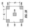
図2A〜Bは、心調律管理デバイス100のような移植式心調律管理デバイスのための集積回路構造の例を示している。図2Aにおいて例証されているのは、ホール効果センサ207A、アナログ・デジタル回路205、ポーリング回路216およびプロセッサ20
3を含むことができるモノリシック集積回路モジュール201の一部分の断面図である。一例において、アナログ・デジタル回路205はアナログ・デジタル変換器である。図2Bは、正方形の幾何学的形状を備えたホール効果センサ207Bの平面図である。一例において、ホール効果センサ207A‐Bは、プロセッサ203A、アナログ・デジタル回路205A、およびポーリング回路216Aと同様に、集積回路モジュールを形成する工程の一部として例えば写真平版法によってパターン形成されてもよい。したがって、ホール効果センサの他の幾何学的形状、例えば十字形のパターン、または1以上の他のパターンの形状を有するものも可能である。様々な例において、ホール効果センサ207Aおよびホール効果センサ207Bは同じセンサである。2A-B show examples of integrated circuit structures for an implantable cardiac rhythm management device, such as the cardiac
2 is a cross-sectional view of a portion of a monolithic
一例において、ポーリング回路216はホール効果センサ207A‐Bに電圧または他の信号を与えるように構成可能である。一例では、アナログ・デジタル回路205は、例えばポーリング回路216によって与えられた1以上の電圧信号に応じた、ホール効果センサ207からの1以上の電流信号または電圧信号を受信し、かつ受信した信号をデジタル信号に変換するように構成されてもよい。一例では、アナログ・デジタル回路205は、例えば磁場の存在または強さの測定において使用するための12ビットの電圧信号をプロセッサ203に提供する。一例では、プロセッサ203はさらに、アナログ・デジタル回路205によって提供されたデジタル信号を、心調律管理デバイス100の付近の磁場強度を推定するために使用することもできる。一例では、プロセッサ203はさらに、心調律管理デバイス100の動作モードを選択するために、アナログ・デジタル回路205によって提供されたデジタル信号から導き出された推定の磁場強度(例えば磁場の大きさ)を、1以上のプログラム可能な閾値またはウィンドウと合わせて使用することもできる。 In one example, the
ある例においては、ホール効果センサ207Aは、p型領域208Aの内部に形成されたn型ウェル209Aを備えている。p型領域210Aは、例えば幅(w)を有する埋め込みn型チャネルを画成するようにn型ウェル209Aの中に形成されることによって、電子のフローを第1接点226A1と第2接点226A2との間の非空乏領域212Aに限定する。一例において、p型領域208Aおよびp型領域210Aは、幅(w)を調整するための各空乏幅の使用による埋め込みn型チャネル内の伝導を制御するために、回路接地のような基準電位に接続されてもよい。n型ウェル209Aおよびp型領域210Aは、ある例ではイオン注入または拡散によって形成可能である。様々な例において、n型ウェル209Aの中のキャリア密度は約1015cm−3〜約1017cm−3であってよい。p型領域208Aとp型領域210Aとの間のn型ウェル209Aの寸法は、ある例では約1マイクロメートルから約3マイクロメートルまでの範囲であってよい。ある例では、p型領域210Aの深さは約0.1マイクロメートル〜約1マイクロメートルであって、5×1017cm−3を超えるキャリア密度を有することができる。p型領域208Aのキャリア密度はおよそ1015cm−3である。様々な例において、p型領域208Aは基板の一領域であり、プロセッサ203、アナログ・デジタル回路205もしくはポーリング回路216、または1以上の他の回路から分離されるように作製可能である。In one example, the
ホール効果センサ207A‐Bは、図2Bの例で示されたように、回転対称な構造であってよい。回転対称な構造は、ゼロに近いオフセット電圧を有することによって、心調律管理デバイス100の付近の磁場の存在を正確に検知するために用いられる測定数を低減することができる。非空乏部分212Aの電流密度は、
(1)J=q2n/m*<τm/(1+(ωcτm)2)>E−q3n/m*2<τ2m/(1+(ωcτm)2)>(E×B)+q4n/m*3<τ3m/(1+(ωcτm)2)>B(E・B)
で表され、上記式中、Jは電流密度ベクトルを表し、Eは電場ベクトルを表し、Bは磁場ベクトルを表し、qは電荷を表し、nは非空乏領域212Aにおける伝導帯キャリア密度
を表し、τmは運動量関係時間(momentum relation time)を表し、m*は伝導帯におけるキャリアの有効質量を表し、ωcはサイクロトロン振動数を表し、<>は、<>内に含まれる変数により与えられる値の平均を表す。初項はホール効果に関係し、第2項および第3項は磁気抵抗効果に関係しうる。式1は、1以上の電流または電圧測定値によって半導体を用いて磁場を検知することを可能にしている。ホール効果センサについて適切な幾何学的形状が選択されれば、磁場を検知するための計算を単純化することができる。The
(1) J = q2 n / m* <τm / (1+ (ωc τm )2 )> E-q3 n / m* 2 <τ2m / (1+ (ωc τm )2 ) > (E × B) + q4 n / m* 3 <τ3 m / (1+ (ωc τm )2 )> B (E · B)
Where J represents the current density vector, E represents the electric field vector, B represents the magnetic field vector, q represents the charge, n represents the conduction band carrier density in the
説明に役立つ例では、非空乏部分212Aの全域で磁束勾配が変わらない場合、磁場ベクトル( In an illustrative example, if the magnetic flux gradient does not change across the

(2)Jx=−qn/Bz<τm>2/<τm2>Ey
で近似可能であり、ホール定数RHは
And the Hall constantRH is
(4)rH=<τm2>/<τm>2
で表すことができる。上記に示されたような、希薄ドープされた非空乏領域212Aについては、rHはほぼ1とすることが可能であり、かつホール移動度は
(5)μH=RHσ=q2n<τm>/m*=μnrH
で表すことが可能であり、上記式中、σは非空乏領域212Aにおけるキャリアの導電率を表し、μnは関連する伝導帯キャリア移動度を表す。上記の幾何学的条件は、磁場をほぼz方向にかけ、y方向の電圧を測定し、x方向の電流を測定することにより得ることができる。したがって、この説明例では、磁場を
(6)Bz=−qn(Ey/Jx)rH
で表すことができる。
Can be expressed as For the lightly doped
Where σ represents the carrier conductivity in the
Can be expressed as
したがって、磁場強度の推定および磁場の存在の同定を行うために、プロセッサ203によりホールセンサ207A‐Bを用いた電圧信号または電流信号の測定が使用される場合がある。したがって、ある例では、ホール効果センサ207A‐Bを使用して、心調律管理デバイスを1以上の異なる動作モード、例えばバッテリ状況試験モードに、または存在しうる磁場強度の様々な程度に応じるようなMRIセーフモードに、切り替えることができる。一例において、ホール効果センサはさらに、電気刺激パルスの送達を妨害し得る磁場を検知すると、心臓治療の送達に対するほぼリアルタイムの時間調整を可能にすることもできる(例えば、心臓治療を抑制するか、強化するか、低下させるか、または他の方法で調節する)。 Therefore, measurement of voltage or current signals using
ホール因子は大幅な測定誤差を引き起こす原因となる可能性があり、したがって考慮される場合がある。この誤差は縮小することができるが、複雑さの付加および適切な計算を行なう際に消費されるバッテリ・エネルギーの点で代償が存在する可能性がある。説明に役立つ例では、一連の8個の電圧・電流測定値を得て、対をなした電圧測定値を平均し、オフセット電圧係数を得て、アルゴリズムまたはルックアップ表のいずれかにより幾何補正係数を得ることにより、補正を行うことができる。本発明者らは、図2Bに示されたような回転対称な構造については、オフセット電圧をほぼ0まで低下させ、より少数の電圧測定値(例えば8個の代わりに2個)を使用してより複雑な計算を必要とすることなく磁場の存在および強さ(例えば大きさ)をより正確に同定することができるとも考えた。幾何補正係数はさらに、回転対称な幾何学的形状については1であってもよく、その結果、測定誤差の発生源としての幾何学的要因を十分に弱めることができる。 Hall factors can cause significant measurement errors and may therefore be considered. While this error can be reduced, there can be a tradeoff in terms of battery energy consumed in adding complexity and making appropriate calculations. In the illustrative example, a series of eight voltage and current measurements are taken, the paired voltage measurements are averaged, the offset voltage coefficient is obtained, and the geometric correction factor is applied by either an algorithm or a lookup table. Can be corrected. We have reduced the offset voltage to near zero for a rotationally symmetric structure as shown in FIG. 2B, using fewer voltage measurements (eg, 2 instead of 8). We also thought that the presence and strength (eg, magnitude) of the magnetic field could be identified more accurately without the need for more complex calculations. Further, the geometric correction factor may be 1 for a rotationally symmetric geometric shape, so that the geometric factor as a source of measurement error can be sufficiently weakened.
ホール効果センサ207A‐Bはn型伝導を有するものとして図2A‐Bに例証されているが、p型伝導を使用して磁場を検知することもできる。そのような例では、n型ウェル209Aにおいてn型キャリアの代わりにp型キャリアが用いられ、p型領域208Aおよびp型領域210Aにおいてはp型キャリアの代わりにn型キャリアが用いられる。そうする際には、得られるホール定数は符号が変更されることになり、この変更はホール効果センサを使用した磁場の検知に必ずしも影響しない。一例において、ホール効果センサは、n型ウェル209Aに直接接触させて金属229Bを配置してショットキー接点構造を形成することにより、またはp型領域210Aの代わりに適切な酸化物を用いて金属・酸化物半導体接点構造を形成することにより、p型領域210Aなしで形成されてもよい。
図3は、移植式心調律管理デバイス付近の磁場を検知する方法300の例を示す。302では、回路116および216のようなポーリング回路は、ホール効果センサ207Bの第1接点226B1と第3接点226B3との間、または第2接点226B2と第4接点226B4との間に1以上の電圧パルスを印加することによって、2以上の接点の間に電流フローを生成させることができる。ほぼ同時に、電圧パルスを受ける必要のない2つの対角線上にある接点の間で電圧を測定することができる。説明に役立つ例では、印加電圧は約2.2ボルトの励起規模を有することができる。電圧パルスは、検知期間の間に消費される電力量を低減するために、低い負荷サイクル(例えば励起パルス幅)で周期的に印加することができる。ある例においては、電圧パルスは、約20〜40マイクロ秒のパルス幅を用いて毎秒約1〜2回の速度(例えば励起パルス反復速度)でホール効果センサに周期的に印加される。接点の間を流れる電流および接点をはさんで生じる電圧は、その後の処理のためにアナログ・デジタル回路105および205のようなアナログ・デジタル回路に送信可能である。アナログ・デジタル回路は、ホール効果センサからプロセッサ103および203のようなプロセッサへと受け渡されたアナログ信号のデジタル化表示を出力することができる。 FIG. 3 shows an example of a
304では、プロセッサは測定可能な磁場が存在するかどうかについて判定するが、この判定は、例えば検知された磁場の大きさを1以上のプログラム可能な閾値と比較することと、検知された大きさが1以上のプログラム可能な閾値と同等であるかまたは閾値を超える場合に磁場が存在すると判定することによって行われる。磁場が検知されない場合、ポーリング回路はホール効果センサの接点に指定された速度で電圧パルスを印加し続ける。1以上のプログラム可能な閾値を使用して、バッテリ・エネルギーを節約するために、プロセッサがホール効果センサによって提供された例えば正常なバックグラウンドの磁場に起因するような弱い磁場に相当する信号については作動しないようにすることができる。 At 304, the processor determines whether there is a measurable magnetic field, which may include, for example, comparing the detected magnetic field magnitude to one or more programmable thresholds and the detected magnitude. Is determined by determining that a magnetic field is present if is equal to or exceeds one or more programmable thresholds. If no magnetic field is detected, the polling circuit continues to apply voltage pulses at the specified rate at the Hall effect sensor contacts. For a signal corresponding to a weak magnetic field, such as due to a normal background magnetic field provided by the processor to save battery energy using one or more programmable thresholds It can be disabled.
306では、磁場を検知すると、心調律管理デバイスの動作は、指定された動作モード、例えばバッテリ状況試験モード、MRIセーフモード、または1つ以上の他の心臓治療モードに設定されうる。動作モード間の切替えは磁場の測定とともにほぼリアルタイムで起こりうる。ある例において、動作モードは磁場の強さ(例えば大きさ)によって選択可能である。一例では、動作モードは検知された磁場の強さに応じて心臓治療の送達を調整するように選択される。 At 306, upon detecting a magnetic field, the operation of the cardiac rhythm management device may be set to a specified operational mode, such as a battery condition test mode, an MRI safe mode, or one or more other cardiac treatment modes. Switching between operating modes can occur in near real time with magnetic field measurements. In one example, the operation mode can be selected according to the strength (eg, magnitude) of the magnetic field. In one example, the mode of operation is selected to adjust the delivery of cardiac therapy as a function of the detected magnetic field strength.
いくつかの例において、動作モードは、磁場の強さが事前の強さの測定値からほとんど変化していない場合、または磁場の強さが指定範囲もしくは指定ゾーン内にある場合には、磁場の検知に応じて変化する必要はない。ある例において、磁場の強さが検知限界値未満である場合、心調律管理デバイスの動作モードは磁場に応じた変化はしない。 In some examples, the mode of operation may be a magnetic field strength if the strength of the magnetic field has changed little from the previous strength measurement, or if the strength of the magnetic field is within a specified range or specified zone. It does not need to change depending on the detection. In an example, when the strength of the magnetic field is less than the detection limit value, the operation mode of the cardiac rhythm management device does not change according to the magnetic field.
308では、ホール効果センサのポーリング速度は磁場の検出に応じて増大または低減されうる。ある例では、プロセッサは、ホール効果センサへの電圧パルスの印加速度を増大させるためにポーリング回路に信号を伝える。ある例では、ポーリング回路に電圧パルス印加速度を変更する信号を送るためにタイミング回路が使用されてもよい。説明に役立つ例において、増大された電圧パルス印加速度は毎秒約20回である。タイミング回路は、電圧パルスがホール効果センサに印加される速度を増大、低減、および再設定するように構成可能である。そのため、タイミング回路は、磁場の検知に応じて指定時間内に印加されうる電圧パルスの総数を制限するためのウィンドウ・タイマーとして使用することができる。例えば、臨床家が患者の心調律管理デバイスの近くに不用意に振り分けマグネットを置き忘れた場合である。 At 308, the polling rate of the Hall effect sensor can be increased or decreased depending on the detection of the magnetic field. In one example, the processor signals the polling circuit to increase the rate of application of voltage pulses to the Hall effect sensor. In one example, a timing circuit may be used to signal the polling circuit to change the voltage pulse application rate. In an illustrative example, the increased voltage pulse application rate is about 20 times per second. The timing circuit can be configured to increase, decrease, and reset the rate at which voltage pulses are applied to the Hall effect sensor. Thus, the timing circuit can be used as a window timer to limit the total number of voltage pulses that can be applied within a specified time in response to magnetic field detection. For example, a clinician inadvertently misplaces a sorting magnet near the patient's cardiac rhythm management device.
308では、ホール効果センサへの電圧パルスの印加速度は、磁場が検知されなくなるか、または強度が指定された値もしくは閾値以下になるまで増大速度に持続することが可能である。 At 308, the rate of application of the voltage pulse to the Hall effect sensor can continue to increase until the magnetic field is no longer detected or the intensity is below a specified value or threshold.
一例において、磁場がもはや検知されない場合、プロセッサはホール効果センサへの電圧パルスの印加の速度を低減する信号をポーリング回路に送る。ある例では、ポーリング速度は、磁場が検知される前に使用された速度に戻される。そのような例では、ポーリング回路は、磁場が再び検知されるまで低減された速度でホール効果センサに電圧パルスを印加し続けることができる。 In one example, if the magnetic field is no longer detected, the processor sends a signal to the polling circuit that reduces the rate of application of the voltage pulse to the Hall effect sensor. In one example, the polling rate is returned to the rate that was used before the magnetic field was detected. In such an example, the polling circuit can continue to apply voltage pulses to the Hall effect sensor at a reduced rate until the magnetic field is detected again.
図4A‐Bは、時間(「t」)に対する検知された磁場の大きさ402のプロット400を、心調律管理デバイス100に関連した1以上のプログラム可能な閾値またはプログラム可能な時間区間に関して示す、例示の実施例である。図4Aに示された例では、ホール効果センサ107のような磁気センサによって提供される情報によれば、時間t1において磁場402は第1の閾値405を越え、第1の閾値405と第2の閾値410との間(例えば図のような閾値ウィンドウ「w」に相当する)にある。一例では、タイマーが始動されて、かつ時間t2において、区間T1のような第1の指定された持続時間全体にわたって磁場402が第1の閾値405以上である場合には、心調律管理デバイス100の異なる動作モードが選択されてもよい。一例では、磁場402が第1の区間T1の全体にわたって大きさウィンドウ「w」内にある場合に、歩行動作モードから別の動作モード、例えばバッテリ状況試験モード、もしくはMRIセーフモードまたは1以上の他のモードへの変更が起きることができる。一例では、第1の高い磁場レベル404Aは、(例えば、患者もしくは医師のようなユーザ、または1以上のバッテリ状態表示を誘発するその他のものによる)心調律管理デバイス100付近への外部永久磁石の配置によって引き起こされる場合もある。4A-B show a
図4Bの例では、磁場402は時間t3で第2の閾値410を越え、第2の区間T2=
t4−t3のような第2の指定された持続時間全体にわたって連続的に第2の閾値410以上である場合がある。一例では、第2の高い磁場レベル404Bは、心調律管理デバイス100の付近に第1の高い磁場レベル404Bより大きな規模を有する外部磁場があることによって引き起こされる場合がある。ある例では、より大きな規模の磁場は、磁気共鳴撮像(MRI)のような診断用医療撮像法に関連した静的磁場または動的磁場によって引き起こされる場合もあれば、溶接、電気式の制御装置もしくは切替装置、またはモーターのような重量機器によって引き起こされる場合もあれば、1以上の他の発生源によって引き起こされる場合もある。一例では、心調律管理デバイス100は、T2の持続時間にわたって第2の閾値410以上である第2の高い磁場レベル404の存在下において、治療を抑制するため、過剰検知を防止するため、または心調律管理デバイス100の動作の不用意もしくは不必要な変化を防止する1以上の他の方法で対応するために、1以上の動作モードを選択することができる。In the example of FIG. 4B, the
It may be continuously greater than or equal to the
一例において、図1に示されたようなプロセッサ103は、1以上の磁気センサを備えた心調律管理デバイスの一部であってよい。この例において、プロセッサ103は1以上の比較測定器を備えることが可能であり、かつプロセッサ103を使用して、例えばアナログ・デジタル変換器105によって提供される磁場のデジタル表示の使用によって、磁場402を第1の閾値405または第2の閾値410のような1以上の閾値と比較することができる。一例において、プロセッサ103は、第1の区間T1、第2の区間T2、または1以上の他の区間のような区間を測定するために1以上のタイマーを内包または制御することができる。一例において、プロセッサ103は、1以上の比較測定器またはタイマーを使用し、かつ図4に示されたような1以上の閾値または区間を使用して、1以上の動作モードを選択することができる。In one example, the
ある例において、ホール効果センサ107は、1以上の他の移植式医療用デバイスに内包された部分、部品または構成要素であってもよい。1以上の他の移植式医療用デバイスには、移植式の患者監視装置、神経性刺激デバイス、または、1以上の組織部位を観察するかもしくは1以上の組織部位に電気刺激を供給するように構成された1以上の他の移植式医療用デバイスを挙げることができる。1以上の他の移植式医療用デバイスは、図1に示されかつ心調律管理デバイス100に関して議論された1以上の構成要素、部品または部分を備えることができる。 In certain examples, the Hall effect sensor 107 may be a portion, component, or component encapsulated in one or more other implantable medical devices. One or more other implantable medical devices may be an implantable patient monitoring device, a neural stimulation device, or to observe one or more electrical sites or provide electrical stimulation to one or more tissue sites One or more other implantable medical devices configured may be mentioned. One or more other implantable medical devices can comprise one or more components, parts, or portions shown in FIG. 1 and discussed with respect to cardiac
補注
上記の詳細な説明は、詳細な説明の一部を形成する添付図面の参照を含んでいる。図面は、例証のために、本発明を実行することができる特定の実施形態を示している。これらの実施形態は本明細書中において「例、実施例(examples)」とも呼ばれる。そのような実施例は図示かつ説明されたもの以外に要素を含むことができる。しかしながら、本発明者らは、図示かつ説明された要素のみを具備する実施例も企図している。Note: The above detailed description includes references to the accompanying drawings, which form a part of the detailed description. The drawings show, by way of illustration, specific embodiments in which the invention can be practiced. These embodiments are also referred to herein as “examples”. Such embodiments may include elements other than those shown and described. However, the inventors also contemplate embodiments that include only the elements shown and described.
本文書において参照された全ての出版物、特許および特許文献は、個々に参照によって組み込まれるかのように、参照によってその全体が本願に組み込まれる。本文書と、参照によってそのように組み込まれた文書との間で矛盾する使用法の場合には、組み込まれた参照文献における使用法は、本文書の使用法への補足と考えるべきであり;両立し難い矛盾については、本文書中の使用法に従う。 All publications, patents and patent documents referred to in this document are hereby incorporated by reference in their entirety as if individually incorporated by reference. In case of conflicting usage between this document and documents so incorporated by reference, usage in the incorporated references should be considered as a supplement to the usage of this document; Follow the usage in this document for incompatible conflicts.
本文書において、用語「1つの(a, an)」は、「少なくとも1つ(at least one)」
または「1以上(one or more)」という他の実例または用法とは無関係に、特許文献に
おいて一般に見られるように1または2以上を含むように使用される。本文書において、用語「または、もしくは(or)」は、別途記載のない限り、非独占的であることを指す、すなわち「AまたはB」は、「AであるがBではない」、「BであるがAではない」、お
よび「AおよびB」を含むことを指すために使用される。添付の特許請求の範囲においては、用語「〜を備えている(including)」および「〜であることを特徴とする(in which)」は、それぞれ用語「〜を含んでなる(comprising)」および「〜であることを特徴
とする(wherein)」の平易な英語による同意語として使用される。同様に、特許請求の
範囲において、用語「〜を備えている(including)」および「〜を含んでなる(comprising)」はオープンエンドである、すなわち、請求項においてそのような用語の後に列挙
された要素以外に要素を備えたシステム、デバイス、物品、または工程もなおその請求項の範囲以内にあると見なされる。さらに、特許請求の範囲において、用語「第1の(first)」、「第2の(second)」および「第3の(third)」などは、単に標識として使用されており、該用語の対象物に番号順の要件を課するようには意図されない。In this document, the term “a, an” means “at least one”.
Or used to include one or more, as commonly found in the patent literature, regardless of other instances or uses of “one or more”. In this document, the term “or” means non-exclusive unless otherwise stated, ie “A or B” means “A but not B”, “B” , But not A "and" A and B "are used to refer to including. In the appended claims, the terms "including" and "in which" are the terms "comprising" and Used as a plain English synonym for “wherein”. Similarly, in the claims, the terms "including" and "comprising" are open-ended, i.e. listed after such terms in the claims. Any system, device, article, or process that includes elements in addition to those elements is still considered to be within the scope of the claims. Further, in the claims, the terms “first”, “second”, “third”, etc. are used merely as labels, It is not intended to impose a numerical order requirement on things.
本明細書中で説明された方法例は、少なくとも一部分が機械またはコンピュータにより実行されてもよい。いくつかの例としては、上記の実施例で説明されたような方法を実施するための電子デバイスを構成するように作動可能な命令がコード化されたコンピュータ可読媒体または機械可読媒体を挙げることができる。そのような方法の実装は、マイクロコード、アセンブリ言語コード、高水準言語コードなどのようなコードを備えることができる。そのようなコードは、様々な方法を実施するためのコンピュータ可読な命令を含むことができる。コードがコンピュータプログラム製品の一部を形成してもよい。さらに、コードは、実行時またはその他の時点で1以上の揮発性または不揮発性のコンピュータ可読媒体上に具体的に格納されていてもよい。これらのコンピュータ可読媒体には、限定するものではないが、ハードディスク、着脱式磁気ディスク、着脱式光ディスク(例えばコンパクトディスクおよびデジタルビデオディスク)、磁気カセット、メモリカードまたはメモリスティック、ランダムアクセスメモリ(RAM)、読み出し専用メモリ(ROM)、などが挙げられる。 The example methods described herein may be performed at least in part by a machine or a computer. Some examples include computer readable or machine readable media encoded with instructions operable to configure an electronic device for performing the methods as described in the above embodiments. it can. An implementation of such a method may comprise code such as microcode, assembly language code, high level language code, and the like. Such code can include computer readable instructions for performing various methods. The code may form part of the computer program product. Further, the code may be specifically stored on one or more volatile or non-volatile computer readable media at runtime or at other times. These computer readable media include, but are not limited to, hard disks, removable magnetic disks, removable optical disks (eg, compact disks and digital video disks), magnetic cassettes, memory cards or memory sticks, and random access memory (RAM). Read-only memory (ROM), and the like.
上記の説明は、例示を意図したものであり、限定を意図したものではない。例えば、上記の実施例(または該実施例の1以上の態様)は互いに組み合わせて使用されてもよい。例えば当業者が上記の説明を概観すれば、他の実施形態を使用することもできる。要約書は、読み手が技術的開示内容の本質をより迅速に確認できるように、米国特許法施行規則第1.72条(b)に準拠するように提供されている。要約書は、特許請求の範囲の範囲または意味を解釈または限定するために使用されることはないという合意を持って提供されている。さらに、上記の詳細な説明においては、様々な特徴が開示内容を簡素化するために一まとめにされる場合がある。これは、請求項に記載されていない開示された特徴が任意の請求項にとって必須であることを意図すると解釈されるべきでない。むしろ、発明の主題は、特定の開示された実施形態のすべての特徴より少ない中に存在しうる。したがって、このように特許請求の範囲は、個別の実施形態として自立している各請求項と共に、詳細な説明に組み込まれる。本発明の範囲は、添付の特許請求の範囲に、そのような特許請求の範囲に付与される等価物の範囲全体を加えた範囲に関して、決定されるべきである。 The above description is intended to be illustrative and not limiting. For example, the above-described examples (or one or more aspects of the examples) may be used in combination with each other. Other embodiments can be used, for example, by those skilled in the art upon reviewing the above description. Abstracts are provided to comply with 37 CFR 1.72 (b) so that readers can more quickly ascertain the nature of the technical disclosure. The Abstract is provided with an agreement that it will not be used to interpret or limit the scope or meaning of the claims. Moreover, in the above detailed description, various features may be grouped together to simplify the disclosure. This should not be interpreted as intending that a disclosed feature not recited in a claim is essential to any claim. Rather, inventive subject matter may lie in less than all features of a particular disclosed embodiment. Thus, the following claims are hereby incorporated into the Detailed Description, with each claim standing on its own as a separate embodiment. The scope of the invention should be determined with reference to the appended claims, along with the full scope of equivalents to which such claims are entitled.
Claims (20)
Translated fromJapanese磁場を検知して磁場に応じて電流または電圧のうち少なくとも一方を提供するように構成されたホール効果センサと、
ホール効果センサに電気的に接続されたプロセッサであって、ホール効果センサによって提供される電流または電圧のうち少なくとも一方を使用して移植式医療用デバイスの動作モードを選択するように構成されたプロセッサと
を備えている、装置。An apparatus comprising an implantable medical device, the implantable medical device comprising:
A Hall effect sensor configured to detect a magnetic field and provide at least one of a current or a voltage according to the magnetic field;
A processor electrically connected to the Hall effect sensor, the processor configured to select an operating mode of the implantable medical device using at least one of a current or a voltage provided by the Hall effect sensor And a device.
プロセッサは電流または電圧のうち少なくとも一方の調整に応じて移植式医療用デバイスの動作モードを選択するように構成されることと
を特徴とする請求項1に記載の装置。The Hall effect sensor is configured to regulate at least one of a current or a voltage provided in response to the magnetic field;
The apparatus of claim 1, wherein the processor is configured to select an operating mode of the implantable medical device in response to adjustment of at least one of current or voltage.
(1)磁場の大きさが指定された第1の閾値未満である場合の第1動作モード、
(2)磁場の大きさが指定された第1の持続時間にわたって指定された第1の閾値を上回るかまたは第1の閾値に等しい場合の第2動作モード、または
(3)磁場の大きさが指定された第2の持続時間にわたって指定された第2の閾値を上回るかまたは第2の閾値に等しい場合の第3動作モード、
のうち少なくとも1つを含むリストから移植式医療用デバイスの動作モードを選択するように構成される、請求項1または2のいずれか1項に記載の装置。Processor
(1) a first operation mode when the magnitude of the magnetic field is less than a specified first threshold;
(2) a second mode of operation where the magnitude of the magnetic field exceeds or is equal to the first threshold for a specified first duration, or (3) the magnitude of the magnetic field is A third mode of operation when the specified second threshold is exceeded or equal to the specified second threshold for a specified second duration;
The apparatus according to claim 1, wherein the apparatus is configured to select an operation mode of the implantable medical device from a list including at least one of the following.
第2動作モードはバッテリ状況試験モードを含み、移植式医療用デバイスはバッテリ状況に応じてユーザに表示を提供するように構成されることと、
第3動作モードは磁気共鳴撮像(MRI)セーフモードを含むことと
を特徴とする請求項3に記載の装置。The first operation mode includes a walking operation mode;
The second mode of operation includes a battery status test mode, wherein the implantable medical device is configured to provide an indication to a user in response to the battery status;
The apparatus of claim 3, wherein the third mode of operation includes a magnetic resonance imaging (MRI) safe mode.
ホール効果センサに電気的に接続され、かつホール効果センサに励起電圧を供給するように構成されたポーリング回路と、
ホール効果センサに電気的に接続され、かつ磁場に応じてホール効果センサによって提
供される電流または電圧のうち少なくとも一方を測定するように構成されたアナログ・デジタル変換器と
を備えている、請求項1〜9のいずれか1項に記載の装置。Implantable medical devices
A polling circuit electrically connected to the Hall effect sensor and configured to supply an excitation voltage to the Hall effect sensor;
An analog-to-digital converter electrically connected to the Hall effect sensor and configured to measure at least one of a current or a voltage provided by the Hall effect sensor in response to a magnetic field. The apparatus of any one of 1-9.
(1)励起振幅、
(2)励起パルス幅、
(3)1つ以上の励起パルスの間のタイミング、または
(4)励起電圧を伝えるための励起接点、
のうち少なくとも1つを含んでなる、請求項10に記載の装置。The processor is configured to control one or more excitation parameters associated with the polling circuit, wherein the one or more excitation parameters are:
(1) excitation amplitude,
(2) excitation pulse width,
(3) timing between one or more excitation pulses, or (4) an excitation contact for conveying the excitation voltage,
The apparatus of claim 10, comprising at least one of:
検知された磁場に応じて電流または電圧のうち少なくとも一方を提供する工程、および
電流または電圧のうち少なくとも一方を使用して移植式医療用デバイスの動作モードを選択する工程、
を含んでなる方法。Detecting a magnetic field using a Hall effect sensor;
Providing at least one of current or voltage in response to the sensed magnetic field, and selecting an operating mode of the implantable medical device using at least one of the current or voltage;
Comprising a method.
該方法は電流または電圧のうち少なくとも一方を監視する工程を含むことと、
移植式医療用デバイスの動作モードを選択する工程は、少なくとも部分的には電流または電圧のうち少なくとも一方を監視する工程に応じて行われることと
を特徴とする、請求項13に記載の方法。Providing at least one of current or voltage includes using a Hall effect sensor;
The method includes monitoring at least one of current or voltage;
14. The method of claim 13, wherein selecting an operating mode of the implantable medical device is performed at least in part in response to monitoring at least one of current or voltage.
検知された磁場の大きさを、指定された第1の閾値または指定された第2の閾値のうち少なくとも一方と比較する工程、および、
比較に応じて、
(1)磁場の大きさが指定された第1の閾値未満である場合の第1動作モード、
(2)磁場の大きさが指定された第1の持続時間にわたって指定された第1の閾値を上回るかまたは第1の閾値に等しい場合の第2動作モード、または
(3)磁場の大きさが指定された第2の持続時間にわたって指定された第2の閾値をさらに上回るかまたは第2の閾値に等しい場合の第3動作モード
のうち少なくとも1つを含むリストから移植式医療用デバイスの動作モードを選択する工程
を含んでなる、請求項13または14のうちいずれか1項に記載の方法。A process of detecting the magnitude of the magnetic field using a Hall effect sensor,
Comparing the magnitude of the detected magnetic field with at least one of a designated first threshold value or a designated second threshold value; and
Depending on the comparison,
(1) a first operation mode when the magnitude of the magnetic field is less than a specified first threshold;
(2) a second mode of operation where the magnitude of the magnetic field exceeds or is equal to the first threshold for a specified first duration, or (3) the magnitude of the magnetic field is The mode of operation of the implantable medical device from a list that includes at least one of the third mode of operation when greater than or equal to the specified second threshold for a specified second duration 15. The method according to any one of claims 13 or 14, comprising the step of selecting
第2動作モードを選択する工程は、バッテリ状況試験モードを選択することを含みかつバッテリ状況に応じてユーザに表示を提供することを含むことと、
第3動作モードを選択する工程は磁気共鳴撮像(MRI)セーフモードを選択することを含むことと
を特徴とする、請求項15に記載の方法。Selecting the first operation mode includes selecting a walking operation mode;
Selecting the second operating mode includes selecting a battery status test mode and including providing an indication to a user in response to the battery status;
The method of claim 15, wherein selecting the third mode of operation includes selecting a magnetic resonance imaging (MRI) safe mode.
ール効果センサを励起する工程を含んでなり、
電流または電圧のうち少なくとも一方を監視する工程は、ホール効果センサに電気的に接続されたアナログ・デジタル変換器を使用することを含むことを特徴とする、請求項13〜16のいずれか1項に記載の方法。Exciting the Hall effect sensor using a polling circuit configured to supply an excitation voltage to the Hall effect sensor;
17. The step of monitoring at least one of current or voltage includes using an analog to digital converter electrically connected to a Hall effect sensor. The method described in 1.
(1)励起振幅、
(2)励起パルス幅、
(3)1つ以上の励起パルスの間のタイミング、または
(4)励起電圧を伝えるための励起接点
のうち少なくとも1つを含む、請求項17に記載の方法。Controlling one or more excitation parameters associated with excitation of the Hall effect sensor, the one or more excitation parameters comprising:
(1) excitation amplitude,
(2) excitation pulse width,
18. The method of claim 17, comprising at least one of (3) timing between one or more excitation pulses, or (4) an excitation contact for conveying an excitation voltage.
検知された大きさを、指定された大きさウィンドウと比較する工程、および
比較に応じて、検知された大きさが指定された持続時間全体にわたって指定されたウィンドウ内にある場合に1つ以上の励起パルスの間のタイミングを大きくする工程
を含んでなる、請求項17または18のうちいずれか1項に記載の方法。A process of detecting the magnitude of the magnetic field using a Hall effect sensor,
Comparing the detected size to a specified size window, and, depending on the comparison, one or more if the detected size is within the specified window for a specified duration. 19. A method according to any one of claims 17 or 18 comprising increasing the timing between excitation pulses.
検知された磁場の大きさを、指定された大きさウィンドウと比較する工程、および
比較に応じて、検知された大きさが指定された第2の持続時間全体にわたって指定されたウィンドウ内にある場合に、指定された第1の持続時間にわたってポーリング回路により送達される励起パルスの総数を制限する工程
を含んでなる、請求項17〜19のいずれか1項に記載の方法。A process of detecting the magnitude of the magnetic field using a Hall effect sensor,
Comparing the magnitude of the detected magnetic field with a specified magnitude window, and, if so, the sensed magnitude is within a specified window for a specified second duration. 20. The method of any one of claims 17-19, further comprising the step of limiting a total number of excitation pulses delivered by the polling circuit for a specified first duration.
Applications Claiming Priority (2)
| Application Number | Priority Date | Filing Date | Title |
|---|---|---|---|
| US745507P | 2007-12-12 | 2007-12-12 | |
| PCT/US2008/013484WO2009075814A1 (en) | 2007-12-12 | 2008-12-08 | Implantable medical device with hall sensor |
Publications (1)
| Publication Number | Publication Date |
|---|---|
| JP2011505964Atrue JP2011505964A (en) | 2011-03-03 |
Family
ID=40394412
Family Applications (1)
| Application Number | Title | Priority Date | Filing Date |
|---|---|---|---|
| JP2010537942APendingJP2011505964A (en) | 2007-12-12 | 2008-12-08 | Implantable medical device with Hall sensor |
Country Status (5)
| Country | Link |
|---|---|
| US (2) | US8121678B2 (en) |
| EP (2) | EP3103517B1 (en) |
| JP (1) | JP2011505964A (en) |
| ES (1) | ES2593091T3 (en) |
| WO (1) | WO2009075814A1 (en) |
Cited By (1)
| Publication number | Priority date | Publication date | Assignee | Title |
|---|---|---|---|---|
| JP2023514094A (en)* | 2020-02-21 | 2023-04-05 | バイオトロニック エスエー アンド カンパニー カーゲー | Implantable medical device configured to detect the presence of an MRI device |
Families Citing this family (60)
| Publication number | Priority date | Publication date | Assignee | Title |
|---|---|---|---|---|
| US7507221B2 (en)* | 2004-10-13 | 2009-03-24 | Mallinckrodt Inc. | Powerhead of a power injection system |
| US8014867B2 (en) | 2004-12-17 | 2011-09-06 | Cardiac Pacemakers, Inc. | MRI operation modes for implantable medical devices |
| US8086321B2 (en) | 2007-12-06 | 2011-12-27 | Cardiac Pacemakers, Inc. | Selectively connecting the tip electrode during therapy for MRI shielding |
| US8032228B2 (en) | 2007-12-06 | 2011-10-04 | Cardiac Pacemakers, Inc. | Method and apparatus for disconnecting the tip electrode during MRI |
| JP2011505964A (en) | 2007-12-12 | 2011-03-03 | カーディアック ペースメイカーズ, インコーポレイテッド | Implantable medical device with Hall sensor |
| WO2010033190A2 (en)* | 2008-09-16 | 2010-03-25 | Cardiac Pacemakers, Inc. | Cardiac function management integrating cardiac contractility modulation |
| US8571661B2 (en) | 2008-10-02 | 2013-10-29 | Cardiac Pacemakers, Inc. | Implantable medical device responsive to MRI induced capture threshold changes |
| US8150516B2 (en)* | 2008-12-11 | 2012-04-03 | Pacesetter, Inc. | Systems and methods for operating an implantable device for medical procedures |
| EP2398553B1 (en) | 2009-02-19 | 2015-07-22 | Cardiac Pacemakers, Inc. | Systems for providing arrhythmia therapy in mri environments |
| US9174058B2 (en) | 2009-09-29 | 2015-11-03 | Medtronic, Inc. | Automatic selection of parameters of an exposure mode of an implantable medical device |
| US8165691B2 (en)* | 2009-10-19 | 2012-04-24 | Medtronic, Inc. | Implantable medical device with selectively configurable exposure operating mode programming options |
| US8260422B2 (en)* | 2009-10-19 | 2012-09-04 | Medtronic, Inc. | Implantable medical device with selectively configurable exposure operating mode programming options |
| US9958515B2 (en)* | 2009-10-30 | 2018-05-01 | Medtronic, Inc. | Configuring operating parameters of a medical device based on a type of source of a disruptive energy field |
| US9205268B2 (en)* | 2009-10-30 | 2015-12-08 | Medtronic, Inc. | Configuring operating parameters of a medical device based on a type of source of a disruptive energy field |
| US8478416B2 (en)* | 2009-11-10 | 2013-07-02 | Med-El Elektromedizinische Geraete Gmbh | Implant power control |
| JP5558583B2 (en)* | 2009-12-08 | 2014-07-23 | カーディアック ペースメイカーズ, インコーポレイテッド | Implantable medical device including automatic tachycardia detection and control in an MRI environment |
| US9919158B2 (en)* | 2009-12-29 | 2018-03-20 | Medtronic, Inc. | Configuring operating parameters of a medical device based on exposure to a disruptive energy field |
| US8538550B2 (en)* | 2009-12-29 | 2013-09-17 | Cardiac Pacemakers, Inc. | Implantable device failsafe mode for MRI |
| US9603549B2 (en)* | 2009-12-30 | 2017-03-28 | Cardiac Pacemakers, Inc. | Implantable device with post-MRI cardiac signal sensing adjustment |
| US8750997B2 (en)* | 2009-12-31 | 2014-06-10 | Cardiac Pacemakers, Inc. | Implantable medical device including isolation test circuit |
| US20110160567A1 (en)* | 2009-12-31 | 2011-06-30 | Stahmann Jeffrey E | Functional mri cardiac optimization |
| US8855784B2 (en)* | 2009-12-31 | 2014-10-07 | Cardiac Pacemakers, Inc. | Implantable medical device including controllably isolated housing |
| EP2347790B1 (en)* | 2010-01-20 | 2013-01-02 | Sorin CRM SAS | Implantable prosthetic heart including a means for detecting and protecting against the strong magnetic fields generated by MRI machines |
| JP5819957B2 (en) | 2010-07-01 | 2015-11-24 | カーディアック ペースメイカーズ, インコーポレイテッド | Treatment circuit protection in implantable medical devices |
| US8744578B2 (en)* | 2010-10-29 | 2014-06-03 | Medtronic, Inc. | Staged sensing adjustments by an implantable medical device in the presence of interfering signals |
| US8983606B2 (en) | 2010-10-29 | 2015-03-17 | Medtronic, Inc. | Enhanced sensing by an implantable medical device in the presence of an interfering signal from an external source |
| US9014807B2 (en) | 2010-12-20 | 2015-04-21 | Cardiac Pacemakers, Inc. | Lead fault detection for implantable medical device |
| US10391320B2 (en) | 2011-01-28 | 2019-08-27 | Medtronic, Inc. | Techniques for detecting magnetic resonance imaging field |
| US9795792B2 (en) | 2011-02-25 | 2017-10-24 | Medtronic, Inc. | Emergency mode switching for non-pacing modes |
| US9272152B2 (en) | 2011-08-31 | 2016-03-01 | Cardiac Pacemakers, Inc. | Remote programming of MRI settings of an implantable medical device |
| CN104105979B (en)* | 2012-02-09 | 2018-05-22 | 皇家飞利浦有限公司 | The data acquisition facility being applied in combination with MRI device |
| US9981124B2 (en) | 2012-04-26 | 2018-05-29 | Medtronic, Inc. | Devices and techniques for detecting magnetic resonance imaging field |
| WO2014004557A1 (en)* | 2012-06-25 | 2014-01-03 | Boston Scientific Neuromodulation Corporation | Neurostimulation system for enabling magnetic field sensing with a shut-down hall sensor |
| TWI487502B (en)* | 2012-10-09 | 2015-06-11 | Quanta Comp Inc | Biophysical signal detection apparatus |
| WO2014107205A2 (en)* | 2012-10-11 | 2014-07-10 | The Penn State Research Foundation | Zero- & Low-Field Transport Detection System |
| AT13271U1 (en)* | 2012-12-20 | 2013-09-15 | Biegler Gmbh | Electric stimulation device |
| US8750961B1 (en)* | 2013-03-07 | 2014-06-10 | Medtronic, Inc. | Implantable medical device having a multi-axis magnetic sensor |
| JP2016516489A (en) | 2013-03-15 | 2016-06-09 | ウィリアム エル ハンター | Apparatus, system and method for monitoring hip replacements |
| CN113274173A (en) | 2013-06-23 | 2021-08-20 | 卡纳里医疗公司 | Devices, systems, and methods for monitoring knee replacements |
| US9724520B2 (en) | 2014-01-30 | 2017-08-08 | Medtronic, Inc. | Methods, implantable medical devices, and systems to continue implementing a special mode of operation after experiencing a device reset |
| EP3160331A4 (en) | 2014-06-25 | 2018-09-12 | Canary Medical Inc. | Devices, systems and methods for using and monitoring orthopedic hardware |
| EP4449979A3 (en) | 2014-06-25 | 2025-05-21 | Canary Medical Switzerland AG | Devices, systems and methods for using and monitoring implants |
| CA3223705A1 (en) | 2014-06-25 | 2015-12-30 | Canary Medical Switzerland Ag | Devices, systems and methods for using and monitoring spinal implants |
| CA2992263A1 (en) | 2014-06-25 | 2015-12-30 | Canary Medical Inc. | Devices, systems and methods for using and monitoring tubes in body passageways |
| US9694187B2 (en)* | 2014-07-16 | 2017-07-04 | Cardiac Pacemakers, Inc. | Implantable medical devices and methods including post-procedural system diagnostics |
| US9399140B2 (en) | 2014-07-25 | 2016-07-26 | Medtronic, Inc. | Atrial contraction detection by a ventricular leadless pacing device for atrio-synchronous ventricular pacing |
| CA2998709A1 (en) | 2014-09-17 | 2016-03-24 | Canary Medical Inc. | Devices, systems and methods for using and monitoring medical devices |
| US11191479B2 (en) | 2016-03-23 | 2021-12-07 | Canary Medical Inc. | Implantable reporting processor for an alert implant |
| KR102854603B1 (en) | 2016-03-23 | 2025-09-04 | 카나리 메디칼 아이엔씨. | Implantable reporting processor for an alert implant |
| US10293167B2 (en) | 2016-04-15 | 2019-05-21 | Medtronic, Inc. | Methods and implantable medical systems that implement exposure modes of therapy that allow for continued operation during exposure to a magnetic disturbance |
| US10286209B2 (en) | 2016-04-29 | 2019-05-14 | Medtronic, Inc. | Methods and implantable medical devices for automatic entry to an exposure mode of operation upon exposure to a magnetic disturbance |
| US11207527B2 (en) | 2016-07-06 | 2021-12-28 | Cardiac Pacemakers, Inc. | Method and system for determining an atrial contraction timing fiducial in a leadless cardiac pacemaker system |
| WO2018044408A1 (en)* | 2016-09-02 | 2018-03-08 | Medtronic, Inc. | Hall sensor circuit for magnetic field detection in implantable medical device |
| WO2019152342A1 (en) | 2018-02-01 | 2019-08-08 | Cardiac Pacemakers, Inc. | An insertable cardiac monitoring device designed for the mri environment |
| US11040213B2 (en)* | 2018-03-06 | 2021-06-22 | Pacesetter, Inc. | Methods and implantable medical devices for detecting a magnetic field |
| US20210366610A1 (en) | 2019-06-06 | 2021-11-25 | Canary Medical Inc. | Intelligent joint prosthesis |
| US12232985B2 (en) | 2019-06-06 | 2025-02-25 | Canary Medical Inc. | Intelligent joint prosthesis |
| CA3172384A1 (en) | 2020-02-20 | 2021-08-26 | Canary Medical Switzerland Ag | Medical device for implanting in boney tissue and characterization of bone fractures |
| US20240050738A1 (en)* | 2022-08-11 | 2024-02-15 | Pacesetter, Inc. | Active implantable medical device |
| CN115363532B (en)* | 2022-08-22 | 2025-07-29 | 苏州无双医疗设备有限公司 | Implantable medical device and system and method for triggering storage thereof |
Citations (11)
| Publication number | Priority date | Publication date | Assignee | Title |
|---|---|---|---|---|
| US4301804A (en)* | 1979-11-28 | 1981-11-24 | Medtronic, Inc. | Pacemaker with Hall effect externally controlled switch |
| JPH05303457A (en)* | 1992-04-28 | 1993-11-16 | Fujitsu Ltd | System for inputting data to integrated circuit by integrated magnetic sensor |
| JPH0611556A (en)* | 1991-12-21 | 1994-01-21 | Deutsche Itt Ind Gmbh | Hole sensor, whose offset is compensated |
| JPH0779032A (en)* | 1993-09-07 | 1995-03-20 | Showa Denko Kk | GaInAs two-dimensional electron Hall element |
| JPH07178186A (en)* | 1992-08-26 | 1995-07-18 | Medtronic Inc | Medical device that can be buried hypodermically |
| JPH0888425A (en)* | 1994-09-19 | 1996-04-02 | Fujitsu Ltd | Hall effect magnetic sensor and thin film magnetic head |
| JP2002515807A (en)* | 1997-03-27 | 2002-05-28 | アルフレッド イー マン ファウンデーション フォア サイエンティフィック リサーチ | Implantable device system for monitoring and / or acting on body parameters |
| JP2005515855A (en)* | 2002-01-29 | 2005-06-02 | メドトロニック・インコーポレーテッド | Implantable medical system that reduces magnetic resonance effects |
| JP2005525179A (en)* | 2002-05-10 | 2005-08-25 | メドトロニック・インコーポレーテッド | Method and apparatus for controlling a pacing system in the presence of EMI |
| WO2007067825A1 (en)* | 2005-12-07 | 2007-06-14 | Advanced Bionics Corporation | Battery protection and zero-volt battery recovery system for an implantable medical device |
| WO2007133947A2 (en)* | 2006-05-09 | 2007-11-22 | Paracor Medical, Inc. | Cardiac harness having diagnostic sensors and method of use |
Family Cites Families (83)
| Publication number | Priority date | Publication date | Assignee | Title |
|---|---|---|---|---|
| US3311111A (en)* | 1964-08-11 | 1967-03-28 | Gen Electric | Controllable electric body tissue stimulators |
| US4721114A (en)* | 1986-02-21 | 1988-01-26 | Cardiac Pacemakers, Inc. | Method of detecting P-waves in ECG recordings |
| US4799493A (en)* | 1987-03-13 | 1989-01-24 | Cardiac Pacemakers, Inc. | Dual channel coherent fibrillation detection system |
| US4793361A (en)* | 1987-03-13 | 1988-12-27 | Cardiac Pacemakers, Inc. | Dual channel P-wave detection in surface electrocardiographs |
| US4799486A (en)* | 1987-03-13 | 1989-01-24 | Cardiac Pacemakers, Inc. | Refractoriless atrial sensing in dual chamber pacemakers |
| EP0553864B1 (en)* | 1992-01-30 | 1999-10-27 | Cardiac Pacemakers, Inc. | Defibrillator waveform generator for generating waveform of long duration |
| DE4444144A1 (en)* | 1994-12-12 | 1996-06-13 | Pacesetter Ab | Pacemaker with improved detection of electrical signals |
| SE9404374D0 (en)* | 1994-12-15 | 1994-12-15 | Pacesetter Ab | magnetic field detector |
| US5759199A (en)* | 1995-08-02 | 1998-06-02 | Pacesetter, Inc. | System and method for ambulatory monitoring and programming of an implantable medical device |
| US5964724A (en)* | 1996-01-31 | 1999-10-12 | Medtronic Electromedics, Inc. | Apparatus and method for blood separation |
| US6058328A (en)* | 1996-08-06 | 2000-05-02 | Pacesetter, Inc. | Implantable stimulation device having means for operating in a preemptive pacing mode to prevent tachyarrhythmias and method thereof |
| SE9603314D0 (en)* | 1996-09-12 | 1996-09-12 | Siemens Elema Ab | Method and apparatus for determining the location of a catheter within the body of a patient |
| US6605057B2 (en)* | 1996-10-24 | 2003-08-12 | Medtronic Ave, Inc. | Reinforced monorail balloon catheter |
| US5713938A (en)* | 1996-11-12 | 1998-02-03 | Pacesetter, Inc. | Fuzzy logic expert system for an implantable cardiac device |
| US6164284A (en) | 1997-02-26 | 2000-12-26 | Schulman; Joseph H. | System of implantable devices for monitoring and/or affecting body parameters |
| US7460911B2 (en) | 1997-02-26 | 2008-12-02 | Alfred E. Mann Foundation For Scientific Research | System and method suitable for treatment of a patient with a neurological deficit by sequentially stimulating neural pathways using a system of discrete implantable medical devices |
| US6198972B1 (en)* | 1997-04-30 | 2001-03-06 | Medtronic, Inc. | Control of externally induced current in implantable medical devices |
| US5961540A (en)* | 1997-09-05 | 1999-10-05 | Pacesetter, Inc. | Pancake annunciator |
| US6239724B1 (en)* | 1997-12-30 | 2001-05-29 | Remon Medical Technologies, Ltd. | System and method for telemetrically providing intrabody spatial position |
| US5978713A (en)* | 1998-02-06 | 1999-11-02 | Intermedics Inc. | Implantable device with digital waveform telemetry |
| US6704602B2 (en)* | 1998-07-02 | 2004-03-09 | Medtronic, Inc. | Implanted medical device/external medical instrument communication utilizing surface electrodes |
| US6263249B1 (en)* | 1999-02-26 | 2001-07-17 | Medtronic, Inc. | Medical electrical lead having controlled texture surface and method of making same |
| US6372283B1 (en)* | 1999-04-02 | 2002-04-16 | Medtronic, Inc. | Plasma process for surface modification of pyrolitic carbon |
| US7149773B2 (en)* | 1999-07-07 | 2006-12-12 | Medtronic, Inc. | System and method of automated invoicing for communications between an implantable medical device and a remote computer system or health care provider |
| US7181505B2 (en)* | 1999-07-07 | 2007-02-20 | Medtronic, Inc. | System and method for remote programming of an implantable medical device |
| US6804558B2 (en)* | 1999-07-07 | 2004-10-12 | Medtronic, Inc. | System and method of communicating between an implantable medical device and a remote computer system or health care provider |
| US6363277B1 (en)* | 1999-08-20 | 2002-03-26 | Cardiac Pacemakers, Inc. | Cardiac rhythm management system with differential sensing channel |
| US6535763B1 (en)* | 1999-08-22 | 2003-03-18 | Cardia Pacemakers, Inc. | Event marker alignment by inclusion of event marker transmission latency in the real-time data stream |
| US6409675B1 (en)* | 1999-11-10 | 2002-06-25 | Pacesetter, Inc. | Extravascular hemodynamic monitor |
| US6277078B1 (en)* | 1999-11-19 | 2001-08-21 | Remon Medical Technologies, Ltd. | System and method for monitoring a parameter associated with the performance of a heart |
| US6572542B1 (en)* | 2000-03-03 | 2003-06-03 | Medtronic, Inc. | System and method for monitoring and controlling the glycemic state of a patient |
| US6580947B1 (en)* | 2000-03-10 | 2003-06-17 | Medtronic, Inc. | Magnetic field sensor for an implantable medical device |
| US6574511B2 (en)* | 2000-04-21 | 2003-06-03 | Medtronic, Inc. | Passive data collection system from a fleet of medical instruments and implantable devices |
| US6510345B1 (en)* | 2000-04-24 | 2003-01-21 | Medtronic, Inc. | System and method of bridging a transreceiver coil of an implantable medical device during non-communication periods |
| US6754526B2 (en)* | 2000-11-13 | 2004-06-22 | Medtronic Physio-Control Corp | Defibrillator with a multiple-mode interface |
| US6564100B2 (en)* | 2000-12-06 | 2003-05-13 | Cardiac Pacemakers, Inc. | Cardiac rhythm management system with remotely activated capture verification for CHF and other patients |
| US6522920B2 (en)* | 2000-12-11 | 2003-02-18 | Pacesetter, Inc. | System and method of protecting transformer-driven switches from external magnetic fields |
| US6665558B2 (en)* | 2000-12-15 | 2003-12-16 | Cardiac Pacemakers, Inc. | System and method for correlation of patient health information and implant device data |
| US7181285B2 (en)* | 2000-12-26 | 2007-02-20 | Cardiac Pacemakers, Inc. | Expert system and method |
| US6901292B2 (en)* | 2001-03-19 | 2005-05-31 | Medtronic, Inc. | Control of externally induced current in an implantable pulse generator |
| US6506457B2 (en)* | 2001-03-30 | 2003-01-14 | Cardiac Pacemakers, Inc. | Lubricious, wear resistant surface coating by plasma polymerization |
| US6807439B2 (en)* | 2001-04-03 | 2004-10-19 | Medtronic, Inc. | System and method for detecting dislodgement of an implantable medical device |
| US6928320B2 (en)* | 2001-05-17 | 2005-08-09 | Medtronic, Inc. | Apparatus for blocking activation of tissue or conduction of action potentials while other tissue is being therapeutically activated |
| US6472991B1 (en)* | 2001-06-15 | 2002-10-29 | Alfred E. Mann Foundation For Scientific Research | Multichannel communication protocol configured to extend the battery life of an implantable device |
| US6662050B2 (en)* | 2001-08-03 | 2003-12-09 | Medtronic, Inc. | Notification of programmed state of medical device |
| US6795732B2 (en)* | 2001-10-30 | 2004-09-21 | Medtronic, Inc. | Implantable medical device employing sonomicrometer output signals for detection and measurement of cardiac mechanical function |
| US7076283B2 (en)* | 2001-10-31 | 2006-07-11 | Medtronic, Inc. | Device for sensing cardiac activity in an implantable medical device in the presence of magnetic resonance imaging interference |
| US6728576B2 (en)* | 2001-10-31 | 2004-04-27 | Medtronic, Inc. | Non-contact EKG |
| US6944489B2 (en)* | 2001-10-31 | 2005-09-13 | Medtronic, Inc. | Method and apparatus for shunting induced currents in an electrical lead |
| US6745079B2 (en)* | 2001-11-07 | 2004-06-01 | Medtronic, Inc. | Electrical tissue stimulation apparatus and method |
| US6959214B2 (en)* | 2001-11-28 | 2005-10-25 | Medtronic, Inc. | Implantable medical device for measuring mechanical heart function |
| US7085604B2 (en)* | 2001-12-28 | 2006-08-01 | Medtronic, Inc. | Mechanical metaphor for representing parameter constraints graphically for medical devices |
| US6937906B2 (en)* | 2002-01-29 | 2005-08-30 | Medtronic, Inc. | Method and apparatus for detecting static magnetic fields |
| US6744152B2 (en)* | 2002-02-25 | 2004-06-01 | Pacesetter, Inc. | Implantable cardioverter defibrillator with switchable power source and patient warning system cardiac device |
| US6931281B2 (en)* | 2002-04-12 | 2005-08-16 | Pacesetter, Inc. | Method and apparatus for monitoring myocardial conduction velocity for diagnostics of therapy optimization |
| US6740076B2 (en)* | 2002-04-26 | 2004-05-25 | Medtronic, Inc. | Ultrasonic septum monitoring for implantable medical devices |
| US20050256508A1 (en)* | 2002-05-07 | 2005-11-17 | Cardiac Pacemakers, Inc. | Guide catheter system having relative markings |
| US20050256503A1 (en)* | 2002-05-07 | 2005-11-17 | Cardiac Pacemakers, Inc. | Tapered catheter delivery system |
| US7037273B2 (en)* | 2002-05-22 | 2006-05-02 | Cardiac Pacemakers, Inc. | Core body temperature monitoring in heart failure patients |
| US6963779B1 (en)* | 2002-05-28 | 2005-11-08 | Pacesetter, Inc. | System for the selective activation of functions in an implantable device by a magnetic field |
| US7276057B2 (en)* | 2002-09-06 | 2007-10-02 | Medtronic, Inc. | Method, system and device for treating disorders of the pelvic floor by drug delivery to the pudendal and sacral nerves |
| SE0202803D0 (en)* | 2002-09-23 | 2002-09-23 | St Jude Medical | Implantable medical device |
| US6656172B1 (en)* | 2002-09-27 | 2003-12-02 | Medtronic, Inc. | Method for treating severe tinnitus |
| US6969383B2 (en)* | 2002-09-27 | 2005-11-29 | Medtronic, Inc. | Method for treating severe tinnitus |
| US7242983B2 (en)* | 2002-10-15 | 2007-07-10 | Medtronic, Inc. | Channel-selective blanking for a medical device system |
| EP1583464B1 (en)* | 2002-10-15 | 2014-04-09 | Medtronic, Inc. | Clustering of recorded patient neurological activity to determine length of a neurological event |
| ATE449561T1 (en)* | 2002-10-15 | 2009-12-15 | Medtronic Inc | PHASE SHIFT OF NEUROLOGICAL SIGNALS IN A MEDICAL DEVICE SYSTEM |
| US7146211B2 (en)* | 2002-10-15 | 2006-12-05 | Medtronic, Inc. | Signal quality monitoring and control for a medical device system |
| EP1565102A4 (en)* | 2002-10-15 | 2008-05-28 | Medtronic Inc | Synchronization and calibration of clocks for a medical device and calibrated clock |
| US7164950B2 (en)* | 2002-10-30 | 2007-01-16 | Pacesetter, Inc. | Implantable stimulation device with isolating system for minimizing magnetic induction |
| US7052486B2 (en)* | 2003-01-02 | 2006-05-30 | Medtronic, Inc. | Method and system for treating depressive and anxiety disorders |
| US7216001B2 (en)* | 2003-01-22 | 2007-05-08 | Medtronic Xomed, Inc. | Apparatus for intraoperative neural monitoring |
| US7158825B1 (en)* | 2003-02-24 | 2007-01-02 | Pacesetter, Inc. | Implantable cardioverter defibrillator with leakage detection and prevention system |
| US7130681B2 (en)* | 2003-05-09 | 2006-10-31 | Medtronic, Inc. | Use of accelerometer signal to augment ventricular arrhythmia detection |
| US7092759B2 (en)* | 2003-07-30 | 2006-08-15 | Medtronic, Inc. | Method of optimizing cardiac resynchronization therapy using sensor signals of septal wall motion |
| US7231251B2 (en)* | 2003-08-14 | 2007-06-12 | Cardiac Pacemakers, Inc. | EMI detection for implantable medical devices |
| AU2004279676B2 (en)* | 2003-10-03 | 2011-10-13 | Uk Investment Associates Llc | Device and method for the treatment of hollow anatomical structures |
| US7123960B2 (en)* | 2003-12-22 | 2006-10-17 | Cardiac Pacemakers, Inc. | Method and system for delivering cardiac resynchronization therapy with variable atrio-ventricular delay |
| US7203540B2 (en)* | 2003-12-22 | 2007-04-10 | Cardiac Pacemakers, Inc. | Method and system for setting cardiac resynchronization therapy parameters |
| US7502644B2 (en)* | 2005-01-25 | 2009-03-10 | Pacesetter, Inc. | System and method for distinguishing among cardiac ischemia, hypoglycemia and hyperglycemia using an implantable medical device |
| US20070036770A1 (en)* | 2005-08-12 | 2007-02-15 | Wagner Darrell O | Biologic device for regulation of gene expression and method therefor |
| US20070173890A1 (en)* | 2006-01-24 | 2007-07-26 | Cyberonics, Inc. | Stimulation mode adjustment for an implantable medical device |
| JP2011505964A (en) | 2007-12-12 | 2011-03-03 | カーディアック ペースメイカーズ, インコーポレイテッド | Implantable medical device with Hall sensor |
- 2008
- 2008-12-08JPJP2010537942Apatent/JP2011505964A/enactivePending
- 2008-12-08WOPCT/US2008/013484patent/WO2009075814A1/enactiveApplication Filing
- 2008-12-08USUS12/330,349patent/US8121678B2/enactiveActive
- 2008-12-08EPEP16174691.2Apatent/EP3103517B1/ennot_activeNot-in-force
- 2008-12-08ESES08860337.8Tpatent/ES2593091T3/enactiveActive
- 2008-12-08EPEP08860337.8Apatent/EP2231271B1/ennot_activeNot-in-force
- 2012
- 2012-02-16USUS13/397,995patent/US8509888B2/enactiveActive
Patent Citations (11)
| Publication number | Priority date | Publication date | Assignee | Title |
|---|---|---|---|---|
| US4301804A (en)* | 1979-11-28 | 1981-11-24 | Medtronic, Inc. | Pacemaker with Hall effect externally controlled switch |
| JPH0611556A (en)* | 1991-12-21 | 1994-01-21 | Deutsche Itt Ind Gmbh | Hole sensor, whose offset is compensated |
| JPH05303457A (en)* | 1992-04-28 | 1993-11-16 | Fujitsu Ltd | System for inputting data to integrated circuit by integrated magnetic sensor |
| JPH07178186A (en)* | 1992-08-26 | 1995-07-18 | Medtronic Inc | Medical device that can be buried hypodermically |
| JPH0779032A (en)* | 1993-09-07 | 1995-03-20 | Showa Denko Kk | GaInAs two-dimensional electron Hall element |
| JPH0888425A (en)* | 1994-09-19 | 1996-04-02 | Fujitsu Ltd | Hall effect magnetic sensor and thin film magnetic head |
| JP2002515807A (en)* | 1997-03-27 | 2002-05-28 | アルフレッド イー マン ファウンデーション フォア サイエンティフィック リサーチ | Implantable device system for monitoring and / or acting on body parameters |
| JP2005515855A (en)* | 2002-01-29 | 2005-06-02 | メドトロニック・インコーポレーテッド | Implantable medical system that reduces magnetic resonance effects |
| JP2005525179A (en)* | 2002-05-10 | 2005-08-25 | メドトロニック・インコーポレーテッド | Method and apparatus for controlling a pacing system in the presence of EMI |
| WO2007067825A1 (en)* | 2005-12-07 | 2007-06-14 | Advanced Bionics Corporation | Battery protection and zero-volt battery recovery system for an implantable medical device |
| WO2007133947A2 (en)* | 2006-05-09 | 2007-11-22 | Paracor Medical, Inc. | Cardiac harness having diagnostic sensors and method of use |
Cited By (2)
| Publication number | Priority date | Publication date | Assignee | Title |
|---|---|---|---|---|
| JP2023514094A (en)* | 2020-02-21 | 2023-04-05 | バイオトロニック エスエー アンド カンパニー カーゲー | Implantable medical device configured to detect the presence of an MRI device |
| JP7599500B2 (en) | 2020-02-21 | 2024-12-13 | バイオトロニック エスエー アンド カンパニー カーゲー | IMPLANTABLE MEDICAL DEVICE CONFIGURED TO DETECT THE PRESENCE OF MRI DEVICE - Patent application |
Also Published As
| Publication number | Publication date |
|---|---|
| US8509888B2 (en) | 2013-08-13 |
| US8121678B2 (en) | 2012-02-21 |
| US20090157146A1 (en) | 2009-06-18 |
| EP3103517A1 (en) | 2016-12-14 |
| WO2009075814A1 (en) | 2009-06-18 |
| US20120150261A1 (en) | 2012-06-14 |
| EP3103517B1 (en) | 2017-10-04 |
| ES2593091T3 (en) | 2016-12-05 |
| EP2231271A1 (en) | 2010-09-29 |
| EP2231271B1 (en) | 2016-06-22 |
Similar Documents
| Publication | Publication Date | Title |
|---|---|---|
| JP2011505964A (en) | Implantable medical device with Hall sensor | |
| US8818506B2 (en) | Detection of strong static magnetic fields and MRI examination safekeeping for an implantable cardiac prosthesis | |
| US8224421B2 (en) | Implantable cardiac stimulator, device and system for monitoring the status of a cardiac lead | |
| EP2198917B1 (en) | Generator for an implantable pacemaker, comprising means for commuting in safety mode during MRI tests | |
| CN103717260B (en) | A device for setting cardiac pacing parameters in a relatively high-efficiency pacing system | |
| US6529777B1 (en) | Electrode for tissue stimulation | |
| JP6295327B2 (en) | Leadless implantable medical device and method | |
| US8750997B2 (en) | Implantable medical device including isolation test circuit | |
| US8321021B2 (en) | Stimulation system, in particular a cardiac pacemaker | |
| US20090210025A1 (en) | Model reference identification and cancellation of magnetically-induced voltages in a gradient magnetic field | |
| JP5740047B2 (en) | Implantable medical system | |
| US20110245888A1 (en) | Medical device with charge leakage detection | |
| JPH06190066A (en) | Heart stimulation device | |
| WO2012148507A1 (en) | Implantable medical device with automatic sensing threshold adjustment in noisy environment | |
| JP5734555B2 (en) | Nerve stimulator | |
| US20110187360A1 (en) | Mri sensor based on the hall effect for crm imd applications | |
| US9603549B2 (en) | Implantable device with post-MRI cardiac signal sensing adjustment | |
| US8855784B2 (en) | Implantable medical device including controllably isolated housing | |
| US8494646B2 (en) | Implantable device | |
| JP2025522699A (en) | Atrial pacing capture verification strategy for intracardiac leadless pacemakers | |
| US20060241398A1 (en) | Methods and apparatus for reducing deleterious effects of x-ray radiation upon implantable medical device circuitry | |
| Crossley | Getting Familiar with Pacemaker Basics |
Legal Events
| Date | Code | Title | Description |
|---|---|---|---|
| RD04 | Notification of resignation of power of attorney | Free format text:JAPANESE INTERMEDIATE CODE: A7424 Effective date:20120215 | |
| A131 | Notification of reasons for refusal | Free format text:JAPANESE INTERMEDIATE CODE: A131 Effective date:20120424 | |
| A601 | Written request for extension of time | Free format text:JAPANESE INTERMEDIATE CODE: A601 Effective date:20120724 | |
| A602 | Written permission of extension of time | Free format text:JAPANESE INTERMEDIATE CODE: A602 Effective date:20120731 | |
| A521 | Request for written amendment filed | Free format text:JAPANESE INTERMEDIATE CODE: A523 Effective date:20120822 | |
| A02 | Decision of refusal | Free format text:JAPANESE INTERMEDIATE CODE: A02 Effective date:20121010 |