JP2011505670A - Suspended particle source - Google Patents
Suspended particle sourceDownload PDFInfo
- Publication number
- JP2011505670A JP2011505670AJP2010536130AJP2010536130AJP2011505670AJP 2011505670 AJP2011505670 AJP 2011505670AJP 2010536130 AJP2010536130 AJP 2010536130AJP 2010536130 AJP2010536130 AJP 2010536130AJP 2011505670 AJP2011505670 AJP 2011505670A
- Authority
- JP
- Japan
- Prior art keywords
- voltage
- plasma column
- cathode
- particle accelerator
- acceleration region
- Prior art date
- Legal status (The legal status is an assumption and is not a legal conclusion. Google has not performed a legal analysis and makes no representation as to the accuracy of the status listed.)
- Granted
Links
- 239000002245particleSubstances0.000titleclaimsabstractdescription135
- 230000001133accelerationEffects0.000claimsabstractdescription70
- 230000005291magnetic effectEffects0.000claimsabstractdescription56
- 230000005684electric fieldEffects0.000claimsdescription23
- 239000003990capacitorSubstances0.000claimsdescription9
- 230000008878couplingEffects0.000claims1
- 238000010168coupling processMethods0.000claims1
- 238000005859coupling reactionMethods0.000claims1
- 150000002500ionsChemical class0.000description22
- 239000007789gasSubstances0.000description12
- TWXDDNPPQUTEOV-FVGYRXGTSA-Nmethamphetamine hydrochlorideChemical compoundCl.CN[C@@H](C)CC1=CC=CC=C1TWXDDNPPQUTEOV-FVGYRXGTSA-N0.000description10
- 238000000605extractionMethods0.000description9
- 238000000034methodMethods0.000description3
- 230000007423decreaseEffects0.000description2
- 230000000694effectsEffects0.000description2
- 239000001257hydrogenSubstances0.000description2
- 229910052739hydrogenInorganic materials0.000description2
- 230000007246mechanismEffects0.000description2
- 239000002184metalSubstances0.000description2
- 229910052751metalInorganic materials0.000description2
- 230000001360synchronised effectEffects0.000description2
- RYGMFSIKBFXOCR-UHFFFAOYSA-NCopperChemical compound[Cu]RYGMFSIKBFXOCR-UHFFFAOYSA-N0.000description1
- UFHFLCQGNIYNRP-UHFFFAOYSA-NHydrogenChemical compound[H][H]UFHFLCQGNIYNRP-UHFFFAOYSA-N0.000description1
- 238000013459approachMethods0.000description1
- 230000005540biological transmissionEffects0.000description1
- 230000015572biosynthetic processEffects0.000description1
- 230000008859changeEffects0.000description1
- 238000006243chemical reactionMethods0.000description1
- 238000001816coolingMethods0.000description1
- 229910052802copperInorganic materials0.000description1
- 239000010949copperSubstances0.000description1
- 238000010586diagramMethods0.000description1
- 230000005294ferromagnetic effectEffects0.000description1
- 150000002431hydrogenChemical class0.000description1
- 238000002955isolationMethods0.000description1
- 239000000463materialSubstances0.000description1
- 230000008569processEffects0.000description1
- 230000005855radiationEffects0.000description1
- 230000004044responseEffects0.000description1
- 238000000926separation methodMethods0.000description1
- XLYOFNOQVPJJNP-UHFFFAOYSA-NwaterSubstancesOXLYOFNOQVPJJNP-UHFFFAOYSA-N0.000description1
Images


Classifications
- H—ELECTRICITY
- H05—ELECTRIC TECHNIQUES NOT OTHERWISE PROVIDED FOR
- H05H—PLASMA TECHNIQUE; PRODUCTION OF ACCELERATED ELECTRICALLY-CHARGED PARTICLES OR OF NEUTRONS; PRODUCTION OR ACCELERATION OF NEUTRAL MOLECULAR OR ATOMIC BEAMS
- H05H13/00—Magnetic resonance accelerators; Cyclotrons
- H05H13/02—Synchrocyclotrons, i.e. frequency modulated cyclotrons
Landscapes
- Physics & Mathematics (AREA)
- Engineering & Computer Science (AREA)
- Plasma & Fusion (AREA)
- Spectroscopy & Molecular Physics (AREA)
- Particle Accelerators (AREA)
- Plasma Technology (AREA)
Abstract
Translated fromJapaneseDescription
Translated fromJapanese本特許出願は、加速領域で中断された粒子源を有する粒子加速器を記載する。 This patent application describes a particle accelerator having a particle source suspended in the acceleration region.
荷電粒子を高エネルギーに加速するために、多くの種類の粒子加速器が開発されてきた。粒子加速器の種類の1つはサイクロトロンである。サイクロトロンでは、真空チャンバ内の1つまたは複数のディーに交流電圧を印加することによって軸方向磁界内で荷電粒子を加速する。ディーという名称は、初期のサイクロトロンの電極の形状を描写したものであるが、サイクロトロンによっては電極がDの文字に似ていないこともある。加速する粒子によって作り出されるらせん軌道は磁界に対して垂直である。粒子がらせん状に外側へ動くときに、加速電界がディー間のギャップに印加されている。高周波(RF)電圧がディー間のギャップ両端間に交流電界を生成する。RF電圧、ひいては電界は、磁界内の荷電粒子の軌道周期と同期しており、そのため粒子は、高周波波形によってギャップを何度も横切りながら加速される。粒子のエネルギーは、印加されたRF電圧のピーク電圧を大きく超えるエネルギーレベルにまで増大する。荷電粒子が加速するにつれて、その質量は相対論的効果により増加する。したがって、粒子が加速するとギャップでの位相整合が変化する。 Many types of particle accelerators have been developed to accelerate charged particles to high energy. One type of particle accelerator is the cyclotron. In a cyclotron, charged particles are accelerated in an axial magnetic field by applying an alternating voltage to one or more dees in a vacuum chamber. The name Dee describes the shape of the electrodes of the early cyclotron, but in some cyclotrons the electrode may not resemble the letter D. The helical trajectory created by the accelerating particles is perpendicular to the magnetic field. As the particles move outward in a spiral, an accelerating electric field is applied to the gap between the dees. A radio frequency (RF) voltage generates an alternating electric field across the gap between the dees. The RF voltage, and thus the electric field, is synchronized with the orbital period of the charged particles in the magnetic field, so that the particles are accelerated many times across the gap by the high frequency waveform. The energy of the particles increases to an energy level that greatly exceeds the peak voltage of the applied RF voltage. As charged particles accelerate, their mass increases due to relativistic effects. Therefore, the phase matching in the gap changes as the particles accelerate.
現在使用されているイソクロナスサイクロトロンおよびシンクロサイクロトロンの2種類のサイクロトロンは、加速粒子の相対論的質量の増加の課題を別々の方法で克服している。イソクロナスサイクロトロンでは、適正な加速を維持するために半径に伴って増大する磁界と共に一定周波数の電圧を使用する。シンクロサイクロトロンでは、軸方向の集束を可能にするために、半径が増大するに伴い減少する磁界を使用し、荷電粒子の相対論的速度によって生じる質量増加に対応するために加速電圧の周波数を変える。 Two cyclotrons, the isochronous cyclotron and the synchrocyclotron currently in use, overcome the problem of increasing the relativistic mass of accelerated particles in different ways. Isochronous cyclotrons use a constant frequency voltage with a magnetic field that increases with radius to maintain proper acceleration. The synchrocyclotron uses a magnetic field that decreases with increasing radius to allow axial focusing and changes the frequency of the acceleration voltage to accommodate the mass increase caused by the relativistic velocity of the charged particles. .
一般に、本特許出願は、磁界を空洞に与えるための磁気構造物と、プラズマカラムを空洞に与えるための粒子源とを含むシンクロサイクロトロンを記載する。粒子源は、プラズマカラムを保持するためのハウジングを有する。ハウジングは、プラズマカラムを露出するように加速領域で中断される。加速領域でプラズマカラムからの粒子を加速するために、電圧源が、高周波(RF)電圧を空洞に与えるように構成される。上記のシンクロサイクロトロンは、以下の1つまたは複数の特徴を単独で、または組み合わせて含むことができる。 In general, this patent application describes a synchrocyclotron that includes a magnetic structure for applying a magnetic field to a cavity and a particle source for applying a plasma column to the cavity. The particle source has a housing for holding a plasma column. The housing is interrupted in the acceleration region to expose the plasma column. A voltage source is configured to apply a radio frequency (RF) voltage to the cavity to accelerate particles from the plasma column in the acceleration region. The synchrocyclotron described above can include one or more of the following features, alone or in combination.
磁界は2テスラ(T)を上回ることができ、粒子は、累進的に半径が増大するらせんの形でプラズマカラムから外に向かって加速する。ハウジングは、プラズマカラムを露出するように加速領域で完全に分離された2つの部分を含むことができる。電圧源は、交流電圧に電気的に接続された第1のディーと、グランドに電気的に接続された第2のディーとを含むことができる。粒子源の少なくとも一部が第2のディーを貫通することができる。シンクロサイクロトロンは、加速領域内に阻止物を含むことができる。阻止物は、プラズマカラムからの粒子のうちの少なくとも一部の加速を阻止するものとすることができる。阻止物は、加速領域とほぼ直交し、プラズマカラムからの特定の位相の粒子を阻止するように構成することができる。 The magnetic field can exceed 2 Tesla (T), and the particles accelerate outward from the plasma column in the form of a spiral with progressively increasing radius. The housing can include two parts that are completely separated in the acceleration region to expose the plasma column. The voltage source can include a first dee electrically connected to the alternating voltage and a second dee electrically connected to ground. At least a portion of the particle source can penetrate the second dee. The synchrocyclotron can include an obstruction in the acceleration region. The blocker may block acceleration of at least some of the particles from the plasma column. The blocker can be configured to block particles of a particular phase from the plasma column substantially perpendicular to the acceleration region.
シンクロサイクロトロンは、プラズマカラムを生成する際に使用するための複数の陰極を含むことができる。陰極は、ガスをイオン化してプラズマカラムを生成するために電圧をパルス化するように動作可能とすることができる。陰極は、約1kVから約4kVの間の電圧でパルス動作するように構成することができる。陰極は、外部熱源によって加熱する必要がない。シンクロサイクロトロンは、RF電圧からの電圧を陰極の少なくとも1つに結合する回路を含むことができる。この回路は容量性回路を含むことができる。 A synchrocyclotron can include a plurality of cathodes for use in generating a plasma column. The cathode can be operable to pulse the voltage to ionize the gas and create a plasma column. The cathode can be configured to pulse with a voltage between about 1 kV and about 4 kV. The cathode does not need to be heated by an external heat source. The synchrocyclotron can include a circuit that couples a voltage from the RF voltage to at least one of the cathodes. The circuit can include a capacitive circuit.
磁気構造物は磁気ヨークを含むことができる。その電圧源は、交流電圧に電気的に接続された第1のディーと、グランドに電気的に接続された第2のディーとを含むことができる。第1のディーと第2のディーは、調整可能共振回路を形成することができる。磁界が印加される空洞は、調整可能共振回路を収容する共振空洞を含むことができる。 The magnetic structure can include a magnetic yoke. The voltage source can include a first dee electrically connected to the alternating voltage and a second dee electrically connected to ground. The first dee and the second dee can form an adjustable resonant circuit. The cavity to which the magnetic field is applied can include a resonant cavity that houses an adjustable resonant circuit.
一般に、本特許出願はまた、ガスを収容する管と、管の第1の端部に隣接する第1の陰極と、管の第2の端部に隣接する第2の陰極とを含む粒子加速器も記載する。第1および第2の陰極は、管に電圧を印加してガスからプラズマカラムを形成するものである。粒子が、加速させるためにプラズマカラムから引き出されて得られる。回路が、外部高周波(RF)電界からエネルギーを陰極の少なくとも1つに結合するように構成される。上記の粒子加速器は、以下の1つまたは複数の特徴を単独で、または組み合わせて含むことができる。 In general, this patent application also includes a particle accelerator including a tube containing a gas, a first cathode adjacent to the first end of the tube, and a second cathode adjacent to the second end of the tube. Also described. The first and second cathodes form a plasma column from a gas by applying a voltage to the tube. Particles are obtained by being extracted from the plasma column for acceleration. A circuit is configured to couple energy from an external radio frequency (RF) electric field to at least one of the cathodes. The particle accelerator described above can include one or more of the following features, alone or in combination.
管は、プラズマカラムから粒子が引き出される加速領域で中断することができる。第1の陰極および第2の陰極は、外部熱源によって加熱される必要がない。第1の陰極は、加速領域の、第2の陰極とは異なる側にあってよい。 The tube can be interrupted at an acceleration region where particles are extracted from the plasma column. The first cathode and the second cathode need not be heated by an external heat source. The first cathode may be on a different side of the acceleration region than the second cathode.
粒子加速器は、RF電界を与えるための電圧源を含むことができる。RF電界は、プラズマカラムからの粒子を加速領域で加速するものとすることができる。そのエネルギーは、電圧源によって与えられるRF電界の一部分を含むことができる。回路は、外部電界からエネルギーを第1の陰極および第2の陰極の少なくとも1つに結合するコンデンサを含むことができる。 The particle accelerator can include a voltage source for providing an RF electric field. The RF electric field may accelerate particles from the plasma column in the acceleration region. The energy can include a portion of the RF field provided by the voltage source. The circuit can include a capacitor that couples energy from an external electric field to at least one of the first cathode and the second cathode.
管は、加速領域の中断箇所で完全に分離されている第1の部分および第2の部分を含むことができる。粒子加速器は、加速領域に阻止物を含むことができる。阻止物は、少なくとも1つの位相の粒子がさらに加速しないようにするために使用することができる。 The tube can include a first portion and a second portion that are completely separated at an interruption in the acceleration region. The particle accelerator can include an obstruction in the acceleration region. The blocker can be used to prevent further acceleration of at least one phase of the particle.
粒子加速器は、RF電界をプラズマカラムに与える電圧源を含むことができる。RF電界は、プラズマカラムからの粒子を加速領域で加速するものとすることができる。RF電界は、15kV未満の電圧を含むことができる。加速領域と交差する磁界を形成するために、磁気ヨークを使用することができる。磁界は、約2テスラ(T)より大きくすることができる。 The particle accelerator can include a voltage source that provides an RF electric field to the plasma column. The RF electric field may accelerate particles from the plasma column in the acceleration region. The RF electric field can include a voltage of less than 15 kV. A magnetic yoke can be used to create a magnetic field that intersects the acceleration region. The magnetic field can be greater than about 2 Tesla (T).
一般に、本特許出願はまた、加速領域で少なくとも部分的に分離されている第1の管部分および第2の管部分を含むペニングイオンゲージ(PIG)源を備える粒子加速器も記載する。第1の管部分および第2の管部分は、加速領域を横切って延びるプラズマカラムを保持するものである。加速領域の電圧を与えるために電圧源が使用される。その電圧は、加速領域でプラズマカラムからの粒子を加速するものである。上記の粒子加速器は、以下の1つまたは複数の特徴を単独で、または組み合わせて含むことができる。 In general, this patent application also describes a particle accelerator comprising a Penning ion gauge (PIG) source that includes a first tube portion and a second tube portion that are at least partially separated in an acceleration region. The first tube portion and the second tube portion hold a plasma column that extends across the acceleration region. A voltage source is used to provide the acceleration region voltage. The voltage accelerates particles from the plasma column in the acceleration region. The particle accelerator described above can include one or more of the following features, alone or in combination.
第1の管部分と第2の管部分は、互いに完全に分離することができる。あるいは、第1の管部分の1つまたは複数の部分だけを、第2の管部分の対応する部分から分離することもできる。この後者の構成では、PIG源は、第1の管部分の一部と第2の管部分との間に物理的接続部を含むことができる。この物理的接続部は、プラズマカラムから出て加速する粒子が物理的接続部にぶつかることなくプラズマカラムから脱出して最初の旋回を完了することを可能にすることができる。 The first tube portion and the second tube portion can be completely separated from each other. Alternatively, only one or more portions of the first tube portion can be separated from the corresponding portions of the second tube portion. In this latter configuration, the PIG source can include a physical connection between a portion of the first tube portion and the second tube portion. This physical connection can allow particles accelerating out of the plasma column to escape from the plasma column and complete the initial turn without hitting the physical connection.
PIG源は、グランドに電気的に接続された第1のディーを貫通することができる。交流電圧源に電気的に接続された第2のディーが、加速領域の電圧を与えることができる。 The PIG source can penetrate a first dee that is electrically connected to ground. A second dee electrically connected to the AC voltage source can provide a voltage in the acceleration region.
粒子加速器は、PIG源を実質的に取り囲む構造物を含むことができる。粒子加速器は磁気ヨークを含むことができ、この磁気ヨークは、加速領域を収容する空洞を画定する。磁気ヨークは、加速領域全体にわたって磁界を発生するものとすることができる。磁界は、少なくとも2テスラ(T)とすることができる。例えば、磁界は少なくとも10.5Tとすることができる。電圧は、15kV未満の高周波(RF)電圧を含むことができる。 The particle accelerator can include a structure that substantially surrounds the PIG source. The particle accelerator can include a magnetic yoke, which defines a cavity that accommodates the acceleration region. The magnetic yoke may generate a magnetic field over the entire acceleration region. The magnetic field can be at least 2 Tesla (T). For example, the magnetic field can be at least 10.5T. The voltage can include a radio frequency (RF) voltage of less than 15 kV.
粒子加速器は、粒子加速器から出る粒子を加速する際に使用するための1つまたは複数の電極を含むことができる。プラズマカラムを生成する際に少なくとも1つの陰極を使用することができる。プラズマカラムを生成する際に使用される少なくとも1つの陰極は、冷陰極(例えば、外部熱源によって加熱されないもの)を含むことができる。容量性回路が、電圧の少なくとも一部を冷陰極に結合することができる。冷陰極は、第1の管部分内および第2の管部分内でガスからプラズマカラムを生成するために、電圧をパルス化するように構成することができる。 The particle accelerator can include one or more electrodes for use in accelerating particles exiting the particle accelerator. At least one cathode can be used in generating the plasma column. At least one cathode used in generating the plasma column can include a cold cathode (eg, one that is not heated by an external heat source). A capacitive circuit can couple at least a portion of the voltage to the cold cathode. The cold cathode can be configured to pulse the voltage to create a plasma column from the gas in the first tube portion and the second tube portion.
上記の特徴のどれでも、本明細書に具体的に記載されていない実施を形成するように組み合わせることができる。 Any of the above features can be combined to form implementations not specifically described herein.
1つまたは複数の例の詳細を、添付の図面および以下の説明で示す。さらなる特徴、態様および利点は、これらの説明、図面、および特許請求の範囲により明らかになろう。 The details of one or more examples are set forth in the accompanying drawings and the description below. Additional features, aspects, and advantages will be apparent from the description, drawings, and claims.
本明細書ではシンクロサイクロトロンをベースとするシステムを記載する。しかし、本明細書に記載の回路および方法は、あらゆる種類のサイクロトロンまたは粒子加速器で使用することができる。 A system based on a synchrocyclotron is described herein. However, the circuits and methods described herein can be used with any type of cyclotron or particle accelerator.
図1Aおよび図1Bを参照すると、シンクロサイクロトロン1は、間隔をあけて配置された2つの強磁性体の磁極4aおよび4bの周りに電気コイル2aおよび2bを含み、これらは磁界を発生するように構成されている。磁極4aおよび4bは、対向する2つのヨークの部分6aおよび6b(断面で示されている)によって画定される。磁極4aと4bの間の空間で真空チャンバ8を画定し、あるいは別個の真空チャンバを磁極4aと4bの間に取り付けることができる。磁界強度は一般に、真空チャンバ8の中心からの距離の関数になり、コイル2aおよび2bの形状と、磁極4aおよび4bの形および材料との選択によってだいたい決まる。 Referring to FIGS. 1A and 1B, the
加速電極は、ディー10およびディー12として画定され、それらの間にギャップ13がある。ディー10は、ある交流電圧電位に接続され、その周波数は、荷電粒子の相対論的質量が増大すること、ならびにコイル2aおよび2bと磁極部分4aおよび4bによって発生する磁界が半径方向に減少すること(真空チャンバ8の中心から測定して)に対応するために、1つの加速周期中に高い周波数から低い周波数に変えられる。したがって、ディー10は高周波(RF)ディーと呼ばれる。ディー10および12の交流電圧の理想的なプロファイルが図2に示されており、以下で詳細に論じる。この例では、RFディー10は、内側が中空の半円筒構造である。ディー12は、「ダミーディー」とも呼ばれ、真空チャンバ壁14で接地されているので中空円筒構造である必要がない。図1Aおよび図1Bに示されるようにディー12は、金属、例えば銅の、スロットを有する細片を含み、このスロットは、RFディー10のほぼ同様のスロットに適合するように形づくられている。ディー12は、RFディー10の面16の鏡像を形成するように形づくることができる。 The acceleration electrodes are defined as
イオン源18は、真空チャンバ8の中心の周りに配置され、以下で説明するように、シンクロサイクロトロンの中心に加速するための粒子(例えば陽子)を供給するように構成される。抽出電極22は、荷電粒子を加速領域から抽出チャネル24の中に導き、それによって荷電粒子ビーム26を形成する。ここで、イオン源18は、加速領域の中に軸方向に挿入されている。 The
ディー10および12、ならびにシンクロサイクロトロン内に含まれる他のハードウェアの部品は、ギャップ13の両端間に振動電界を生成する振動電圧入力のもとで調整可能共振回路を画定する。結果として真空チャンバ8内に共振空洞が得られる。この共振空洞の共振周波数は、掃引されるその周波数を同期させることによって、そのQ値を高く保持するように調整することができる。一例では、共振空洞の共振周波数は、ある時間にわたって、例えば1ミリ秒(ms)にわたって約30メガヘルツ(MHz)から約135MHzの範囲(VHF領域)内を移動、または「掃引」する。別の例では、共振空洞の共振周波数は、約1ms内に約95MHzと約135MHzの間で移動、または掃引する。空洞の共振は、「Matching A Resonant Frequency Of A Resonant Cavity To A Frequency Of An Input Voltage」という名称の米国特許出願第11/948,359号(整理番号17970-011001)に記載されている方法で制御することができる。同出願の内容を参照により全部を記載されたものとして本明細書に組み込む。
Q値は、共振周波数に近い周波数に対する共振系の応答に関する共振系の「特性」の尺度である。この例では、Q値は次式で定義される。 The Q value is a measure of the “characteristic” of the resonant system with respect to the response of the resonant system to frequencies close to the resonant frequency. In this example, the Q value is defined by:

ここで、Rは共振回路の能動抵抗、Lはインダクタンス、Cは共振回路の静電容量である。 Here, R is the active resistance of the resonance circuit, L is the inductance, and C is the capacitance of the resonance circuit.
調整機構は、例えば可変インダクタンスコイルまたは可変静電容量とすることができる。可変静電容量デバイスは、振動片リードまたは回転コンデンサとすることができる。図1Aおよび図1Bに示された例では、調整機構は回転コンデンサ28を含む。回転コンデンサ28は、モータ31によって駆動される回転ブレード30を含む。モータ31の各周期中、ブレード30がブレード32と噛み合うにつれて、ディー10および12と回転コンデンサ28を含む共振回路の静電容量が増加し、共振周波数が低下する。この過程は、ブレードが噛み合わなくなるにつれ逆になる。すなわち、共振周波数は、共振回路の静電容量を変化させることによって変わる。こうすることは、粒子ビームを加速するのに必要な周波数でディー/ダミーディーのギャップに印加される高電圧を発生させるために必要な電力を大きな率で低減するという目的に役立つ。ブレード30および32の形状は、必要な共振周波数の時間依存性を生じさせるように機械加工することができる。 The adjustment mechanism can be, for example, a variable inductance coil or a variable capacitance. The variable capacitance device may be a resonator element lead or a rotating capacitor. In the example shown in FIGS. 1A and 1B, the adjustment mechanism includes a rotating
ブレードの回転は、RF周波数発生と同期させることができるので、シンクロサイクロトロンによって画定される共振回路の周波数は、共振空洞に印加される交流電圧電位の周波数の近くに保持される。このことは、RFディーにかかるRF電圧への印加RF電力の効率的な変換を促進する。 Since the blade rotation can be synchronized with the RF frequency generation, the frequency of the resonant circuit defined by the synchrocyclotron is kept close to the frequency of the alternating voltage potential applied to the resonant cavity. This facilitates efficient conversion of the applied RF power to the RF voltage applied to the RF dee.
真空ポンプシステム40は、加速ビームを散乱させなくするために(あるいは相対的に散乱をほとんどなくするために)、またRFディーからの放電を実質的に防止するために、真空チャンバ8を非常に低圧に維持する。 The
シンクロサイクロトロンにおいて実質的に均一な加速を実現するために、ディーギャップの両端間の電界の周波数および振幅を変化させて相対論的質量増加、および磁界の半径方向変化に対応すると共に、粒子ビームの集束を維持する。磁界の半径方向変化は、荷電粒子の外に向かうらせん軌道の中心からの距離に従って測定される。 In order to achieve substantially uniform acceleration in the synchrocyclotron, the frequency and amplitude of the electric field across the dee-gap are varied to accommodate the relativistic mass increase and the radial variation of the magnetic field, Maintain focus. The radial change of the magnetic field is measured according to the distance from the center of the spiral trajectory going out of the charged particle.
図2は、シンクロサイクロトロンにおいて荷電粒子を加速するために必要になりうる理想的な波形を示すものである。これは数周期の波形だけを示し、理想的な周波数変調および振幅変調のプロファイルを必ずしも表していない。図2は、シンクロサイクロトロンで使用される波形の、時間で変化する振幅および周波数の特性を示す。周波数は、粒子速度が光速のかなりの割合に近づくと同時に粒子の相対論的質量が増大するにつれ、高い周波数から低い周波数に変化する。 FIG. 2 shows an ideal waveform that may be required to accelerate charged particles in a synchrocyclotron. This shows only a few cycles of the waveform and does not necessarily represent the ideal frequency and amplitude modulation profiles. FIG. 2 shows the time-varying amplitude and frequency characteristics of the waveform used in the synchrocyclotron. The frequency changes from a higher frequency to a lower frequency as the particle relativistic mass increases as the particle velocity approaches a significant fraction of the speed of light.
イオン源18は、RF電界(電圧)によって粒子をその上で活動化できるシンクロサイクロトロン中央平面に粒子が存在するように、シンクロサイクロトロン1の磁気中心の近くに配置される。このイオン源は、ペニングイオンゲージ(PIG)形状を有することができる。PIG形状では、2つの高電圧陰極が互いにほぼ向かい合わせで配置される。例えば、1つの陰極が加速領域の一方の側にあり、1つの陰極が加速領域の他方の側に磁力線に沿ってあってよい。イオン源アセンブリのダミーディーハウジング12は接地電位とすることができる。アノードは、加速領域に向かって延びる管を含む。比較的少量のガス(例えば、水素/H2)が陰極間の管の中の領域を占める場合、ある電圧を陰極に印加することによって、そのガスからプラズマカラムを形成することができる。印加された電圧により電子が磁力線に沿って管壁に本質的に平行に流れ、管の内部に集められるガス分子をイオン化し、それによってプラズマカラムが生成される。The
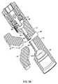
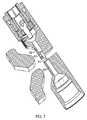
シンクロサイクロトロン1で使用するためのPIG形状イオン源が、図3Aおよび図3Bに示されている。図3Aを参照すると、イオン源18は、ガスを受け取るためのガス供給器39を収容するエミッタ側38a、および反射器側38bを含む。ハウジングまたは管44は、後述のようにガスを保持する。図3Bは、ダミーディー12を貫通しRFディー10に隣接するイオン源18を示す。動作の際、RFディー10とダミーディー12の間の磁界により、粒子(例えば陽子)が外に向かって加速する。加速は、プラズマカラムの周りでらせん状になり、粒子〜プラズマカラムの半径が累進的に増大する。このらせん状加速は、図5および図6で43と表示されている。らせんの曲率半径は、粒子の質量、RF電界によって粒子に与えられたエネルギー、および磁界の強さによって決まる。 A PIG-shaped ion source for use with the
高い磁界の場合、加速中に粒子がその初期の旋回でイオン源の物理的ハウジングを通過するのに十分な大きい曲率半径を有するように、粒子に十分なエネルギーを与えることが困難になりうる。磁界は、イオン源の領域では相対的に高く、例えば2テスラ(T)以上の程度(例えば、8T、8.8T、8.9T、9T、10.5T、またはそれ以上)である。この相対的に高い磁界のために、粒子〜イオン源の初期の半径は、低エネルギー粒子では相対的に小さい。ここで低エネルギー粒子には、プラズマカラムから最初に引き出される粒子が含まれる。例えば、このような半径は1mm程度でありうる。半径が少なくとも初期ではそれほど小さいので、一部の粒子はイオン源のハウジング部分と接触することがあり、それによって、このような粒子がさらに外に向かって加速することが妨げられる。それゆえに、イオン源18のハウジングは、図3Bに示されるように、2つの部分を形成するように中断すなわち分離される。すなわち、イオン源のハウジングの一部分が、加速領域41で、例えば粒子がイオン源から引き出されるべき箇所の近くで除去される。この中断部は、図3Bで45と表示されている。ハウジングはまた、加速領域の上または下で、ある長さにわたって除去することもできる。ダミーディー12の加速領域のところのすべてまたは一部もまた、除去されることもあり除去されないこともある。 For high magnetic fields, it can be difficult to provide sufficient energy to the particles so that during acceleration, the particles have a sufficiently large radius of curvature to pass through the physical housing of the ion source in their initial rotation. The magnetic field is relatively high in the region of the ion source, for example, on the order of 2 Tesla (T) or more (eg, 8T, 8.8T, 8.9T, 9T, 10.5T or more). Because of this relatively high magnetic field, the initial radius of the particle to ion source is relatively small for low energy particles. Here, the low energy particles include particles that are initially extracted from the plasma column. For example, such a radius can be on the order of 1 mm. Because the radius is so small, at least initially, some particles may come into contact with the housing portion of the ion source, thereby preventing such particles from accelerating further outward. Therefore, the housing of the
図3Aおよび図3Bの例では、ハウジング44は、加速されるべき粒子を含むプラズマカラムが保持される管を含む。図示のように、管は異なる箇所で異なる直径を有することができる。管は、ダミーディー12の内側に存在することができるが、これが必要ということではない。シンクロサイクロトロンの中央面の近くで管の一部分が完全に除去され、その結果、別個の2つの部分からなり、これらの部分の間に中断部45があるハウジングが得られる。この例では、中断部は1ミリメートル(mm)から3mmである(すなわち、管のうち約1mmから3mmが除去される)。除去される管の分量は、プラズマカラムからの粒子の加速を可能にするには十分に大きいが、中断部分でのプラズマカラムの著しい消散を妨げるには十分に小さいものとすることができる。 In the example of FIGS. 3A and 3B, the
粒子加速領域の物理的構造物、ここでは管、を除去することによって、粒子は相対的に小さな半径で、例えば相対的に高い磁界の存在下で、さらなる加速を妨げる物理的構造物と接触することなく、初期の旋回を行うことができる。初期の旋回は、磁界およびRF電界の強さに応じて、プラズマカラムを通って後ろで交差することさえありうる。 By removing the physical structure in the particle acceleration region, here the tube, the particle comes into contact with a physical structure that prevents further acceleration at a relatively small radius, for example in the presence of a relatively high magnetic field. The initial turning can be performed without any problems. The initial swirl can even cross back through the plasma column, depending on the strength of the magnetic and RF fields.
管は、相対的に小さな、例えば約2mmの内径を有することができる。このことが、やはり相対的に細いプラズマカラムをもたらし、したがって、粒子が加速を開始できる当初の半径方向位置の相対的に小さな組を与える。管はまた、プラズマカラムを生成するために使用される陰極46から十分に遠く離れており、この例では、各陰極から約10mm離れている。これら2つの特徴は組み合わされて、シンクロサイクロトロン内への水素(H2)ガスの流量を1標準立方センチメートル/分(SCCM)未満に低減し、それによって、シンクロサイクロトロンRF/ビーム空洞の中への相対的に小さな真空コンダクタンスアパーチャと、相対的に小さな容量、例えば約500リットル/秒の真空ポンプシステムとを用いてシンクロサイクロトロンを動作させることが可能になる。The tube can have a relatively small inner diameter, for example about 2 mm. This again results in a relatively thin plasma column, thus providing a relatively small set of initial radial positions where the particles can begin to accelerate. The tube is also far enough away from the
管を中断することはまた、プラズマカラム中へのRF電界の透過増大も助ける。すなわち、中断部に存在する物理的構造物がないので、RF電界は容易にプラズマカラムに達することができる。さらに、管の中断部により、別々のRF電界を用いてプラズマカラムから粒子を加速することが可能になる。例えば、より低いRF電界を用いて粒子を加速することができる。これにより、RF電界を発生させるために使用されるシステムの電力要件を軽減することができる。一例では、20キロワット(kW)のRFシステムでは、プラズマカラムから粒子を加速するために15キロボルト(kV)のRF電界を発生させる。より低いRF電界を使用すると、RFシステム冷却要件およびRF電圧隔離要件が軽減される。 Interrupting the tube also helps increase the transmission of the RF field into the plasma column. That is, since there is no physical structure present in the interrupted portion, the RF electric field can easily reach the plasma column. Furthermore, the interruption of the tube allows particles to be accelerated from the plasma column using a separate RF field. For example, particles can be accelerated using a lower RF field. This can reduce the power requirements of the system used to generate the RF electric field. In one example, a 20 kilowatt (kW) RF system generates a 15 kilovolt (kV) RF field to accelerate particles from the plasma column. Using a lower RF field reduces RF system cooling requirements and RF voltage isolation requirements.
本明細書に記載のシンクロサイクロトロンでは、粒子ビームは、共振抽出システムを使用して抽出される。すなわち、ビームの半径方向振動の振幅は、これらの振動と共振している加速器内部の磁気摂動によって増大される。共振抽出システムが使用される場合、内部ビームの位相空間範囲を制限することによって抽出効率が改善される。磁界およびRF電界の発生構造物の設計に注目すると、抽出時のビームの位相空間範囲は、加速の開始時(例えば、イオン源から出現時)の位相空間範囲によって決まる。その結果、抽出チャネルの入口で失われる可能性があるビームは相対的にほとんどなく、加速器からの背景放射を低減することができる。 In the synchrocyclotron described herein, the particle beam is extracted using a resonant extraction system. That is, the amplitude of the radial vibrations of the beam is increased by magnetic perturbations inside the accelerator that are resonating with these vibrations. When a resonant extraction system is used, extraction efficiency is improved by limiting the phase space range of the internal beam. Focusing on the design of the structure that generates the magnetic field and the RF electric field, the phase space range of the beam at the time of extraction is determined by the phase space range at the start of acceleration (eg, when it emerges from the ion source). As a result, there is relatively little beam that can be lost at the entrance of the extraction channel, and background radiation from the accelerator can be reduced.
物理的な構造物、すなわち阻止物を設けて、シンクロサイクロトロンの中央領域から流出することが可能な粒子の位相を制御することができる。このような阻止物51の一例が図6に示されている。阻止物51は、特定の位相を有する粒子を阻止する障害物として機能する。すなわち、障害物に当たった粒子はさらに加速することが妨げられるのに対して、阻止物を通過した粒子は、シンクロサイクロトロンから出て加速を続ける。粒子エネルギーが例えば50kV未満と低い場合に、粒子の初期の旋回中に位相を選択するために、阻止物は、図6に示されるようにプラズマカラムの近くにあってよい。あるいは、阻止物は、プラズマカラムに対して他の任意の箇所に配置されてもよい。図6に示された例では、単一の阻止物がダミーディー12上に配置されている。しかし、1つのディー当たりに複数の阻止物(図示せず)があってもよい。 A physical structure, i.e., an obstruction, can be provided to control the phase of particles that can exit the central region of the synchrocyclotron. An example of such an obstruction 51 is shown in FIG. The blocker 51 functions as an obstacle that blocks particles having a specific phase. That is, the particles that hit the obstacle are prevented from further accelerating, whereas the particles that have passed the obstacle exit the synchrocyclotron and continue to accelerate. In order to select the phase during the initial swirling of the particles when the particle energy is low, eg below 50 kV, the obstruction may be near the plasma column as shown in FIG. Alternatively, the obstruction may be placed at any other location relative to the plasma column. In the example shown in FIG. 6, a single obstruction is placed on the
陰極46は、「冷」陰極とすることができる。冷陰極は、外部熱源によって加熱されない陰極とすることができる。また、陰極はパルス動作させることもでき、これは、陰極が連続的ではなく周期的に信号バーストを出力するということである。陰極が冷陰極であり、パルス動作される場合、陰極は損耗しにくくなり、したがって相対的に長持ちしうる。さらに、陰極をパルス動作させると陰極を水冷する必要をなくすることができる。一実施では、陰極46は、相対的に高い例えば約1kV〜約4kVの電圧と、約0.1%と約1%または2%の間のデューティサイクルで約200Hz〜約1kHzの間の繰返し周波数の、約50mA〜約200mAの中程度のピーク陰極放電電流とでパルス動作する。
冷陰極は、場合によりタイミングジッタおよび点火遅れを引き起こしうる。すなわち、陰極に十分な熱がないことが、印加電圧に応じて電子が放電する時間に影響を及ぼしうる。例えば、陰極が十分に加熱されていない場合、放電は予想よりも数マイクロ秒以上遅れて、あるいは長く起こりうる。これはプラズマカラムの形成に影響を及ぼし、したがってまた、粒子加速器の動作に影響を及ぼしうる。これらの影響を打ち消すために、空洞8内のRF電界からの電圧を陰極に結合することができる。そうしない場合には陰極46は、ファラデー遮蔽を形成してRF電界から陰極を実質的に遮蔽する金属の中に入れられる。一実施では、RFエネルギーの一部をRF電界から陰極に結合することができ、例えば約100VをRF電界から陰極に結合することができる。図3Bは、ここではコンデンサである容量性回路54がRF電界によって充電されて陰極46に電圧を供給する一実施を示す。RFチョークおよび直流給電を用いてコンデンサを充電することができる。別の陰極46では、相当する構成(図示せず)を実施することができる。結合されるRF電圧によりタイミングジッタを低減し、実施によっては放電遅れを約100ナノ秒(ns)以下にまで低減することができる。 Cold cathodes can sometimes cause timing jitter and ignition delay. That is, the lack of sufficient heat at the cathode can affect the time for which electrons are discharged depending on the applied voltage. For example, if the cathode is not sufficiently heated, the discharge can occur a few microseconds later or longer than expected. This affects the formation of the plasma column and can therefore also affect the operation of the particle accelerator. To counteract these effects, the voltage from the RF field in the cavity 8 can be coupled to the cathode. Otherwise, the
一代替実施形態が図7に示されている。この実施形態では、PIG源ハウジングの全部ではないがかなりの部分が除去され、それによってプラズマビームが部分的に露出したままになる。すなわち、PIGハウジングの一部分がその相手側部分から分離されるが、上記の場合のような完全な分離はない。残っている部分61は、PIG源の第1の管部分62と第2の管部分63を物理的に接続している。この実施形態では、粒子が、ハウジングが残っている部分61に当たらずに、少なくとも1回の旋回(軌道周回)を行うことが可能になるのに十分なだけのハウジングが除去される。一例では、最初の旋回半径は1mmとすることができるが、他の旋回半径を実施することもできる。図7に示された実施形態は、本明細書に記載の他のどの特徴とも組み合わせることができる。 An alternative embodiment is shown in FIG. In this embodiment, a substantial but not all of the PIG source housing is removed, thereby leaving the plasma beam partially exposed. That is, a portion of the PIG housing is separated from its counterpart, but there is no complete separation as in the above case. The remaining
本明細書に記載の粒子源および付随の特徴は、シンクロサイクロトロンでの使用に限定されるのではなく、任意の種類の粒子加速器またはサイクロトロンで使用することができる。さらに、PIG形状を有するもの以外のイオン源が、任意の種類の粒子加速器で使用されてもよく、また、中断部分、冷陰極、阻止物、および/または本明細書に記載の他の任意の特徴を有することもできる。 The particle sources and associated features described herein are not limited to use with synchrocyclotrons, but can be used with any type of particle accelerator or cyclotron. Further, ion sources other than those having a PIG shape may be used in any type of particle accelerator, and may be interrupted portions, cold cathodes, obstructions, and / or any other described herein. It can also have features.
本明細書に記載のそれぞれ異なる実施の構成要素は、上記に具体的に示されていない他の実施形態を形成するように組み合わせることができる。本明細書に具体的に記載されていない他の実施もまた、以下の特許請求の範囲の中にある。 The different implementation components described herein can be combined to form other embodiments not specifically shown above. Other implementations not specifically described herein are also within the scope of the following claims.
2a 電気コイル
2b 電気コイル
4a 磁極
4b 磁極
6a ヨークの部分
6b ヨークの部分
8 真空チャンバ
10 ディー
12 ディー、ダミーディー
13 ギャップ
14 真空チャンバ壁
16 ディーの面
18 イオン源
22 抽出電極
24 抽出チャネル
26 荷電粒子ビーム
28 回転コンデンサ
30 ブレード
31 モータ
32 ブレード
38a エミッタ側
38b 反射器側
39 ガス供給器
40 真空ポンプシステム
41 加速領域
43 らせん状加速
44 ハウジング
45 中断部
46 陰極
51 阻止物
54 容量性回路
61 ハウジングが残っている部分
62 PIG源の第1の管部分
63 PIG源の第2の管部分2a electric coil
2b electric coil
4a magnetic pole
4b magnetic pole
6a Yoke part
6b Yoke part
8 Vacuum chamber
10 Dee
12 Dee, Dummy Dee
13 gap
14 Vacuum chamber wall
16 Dee's Face
18 Ion source
22 Extraction electrode
24 extraction channels
26 Charged particle beam
28 Rotating capacitor
30 blade
31 Motor
32 blade
38a Emitter side
38b Reflector side
39 Gas supply
40 Vacuum pump system
41 Acceleration region
43 Spiral acceleration
44 Housing
45 Interruption
46 Cathode
51 Obstacle
54 Capacitive circuit
61 Where the housing remains
62 First pipe part of PIG source
63 Second pipe part of PIG source
Claims (32)
Translated fromJapanese前記空洞にプラズマカラムを与える粒子源であって、前記プラズマカラムを保持するハウジングを有し、前記ハウジングが、前記プラズマカラムを露出するように加速領域で中断されている、粒子源と、
前記加速領域で前記プラズマカラムからの粒子を加速するために前記空洞に高周波(RF)電圧を与える電圧源とを含むシンクロサイクロトロン。A magnetic structure that applies a magnetic field to the cavity;
A particle source for providing a plasma column to the cavity, the particle source having a housing holding the plasma column, the housing being interrupted in an acceleration region to expose the plasma column;
A synchrocyclotron including a voltage source for applying a radio frequency (RF) voltage to the cavity to accelerate particles from the plasma column in the acceleration region.
前記粒子源の少なくとも一部が前記第2のディーを貫通する、請求項1に記載のシンクロサイクロトロン。The voltage source includes a first dee electrically connected to an alternating voltage and a second dee electrically connected to ground;
The synchrocyclotron according to claim 1, wherein at least a part of the particle source penetrates the second dee.
前記陰極が外部熱源によって加熱されない、請求項1に記載のシンクロサイクロトロン。A cathode for use in generating the plasma column, further comprising a cathode operable to pulse a voltage to ionize a gas to generate the plasma column;
The synchrocyclotron according to claim 1, wherein the cathode is not heated by an external heat source.
前記管の第1の端部に隣接する第1の陰極と、
前記管の第2の端部に隣接する第2の陰極とを含み、前記第1および第2の陰極が前記管に電圧を印加して前記ガスからプラズマカラムを形成し、
粒子が、加速させるために前記プラズマカラムから引き出されて得られ、さらに
外部高周波(RF)電界からエネルギーを前記陰極の少なくとも1つに結合する回路を含む粒子加速器。A tube containing gas,
A first cathode adjacent to the first end of the tube;
A second cathode adjacent to the second end of the tube, the first and second cathodes applying a voltage to the tube to form a plasma column from the gas;
A particle accelerator comprising particles obtained by being extracted from the plasma column for acceleration and further coupling energy from an external radio frequency (RF) electric field to at least one of the cathodes.
前記第1の陰極および前記第2の陰極が外部熱源によって加熱されない、請求項12に記載の粒子加速器。The tube is interrupted in an acceleration region where the particles are withdrawn from the plasma column;
13. The particle accelerator of claim 12, wherein the first cathode and the second cathode are not heated by an external heat source.
前記加速領域と交差する約2テスラ(T)より大きい磁界を形成するための磁気ヨークとをさらに含む、請求項13に記載の粒子加速器。A voltage source for applying an RF electric field to the plasma column for accelerating the particles from the plasma column in the acceleration region, wherein the RF electric field includes a voltage of less than 15 kV;
14. The particle accelerator of claim 13, further comprising a magnetic yoke for forming a magnetic field greater than about 2 Tesla (T) intersecting the acceleration region.
前記加速領域でプラズマカラムからの粒子を加速する前記加速領域の電圧を与える電圧源とを含む粒子加速器。A Penning ion gauge (PIG) source including a first tube portion and a second tube portion that are at least partially separated in an acceleration region, wherein the first tube portion and the second tube portion are: A Penning ion gauge (PIG) source holding a plasma column extending across the acceleration region;
A particle accelerator including a voltage source for applying a voltage in the acceleration region to accelerate particles from the plasma column in the acceleration region.
前記PIG源が、前記第1の管部分の一部と前記第2の管部分との間に物理的接続部を含み、前記物理的接続部が、前記プラズマカラムから出て加速する粒子が前記物理的接続部にぶつかることなく前記プラズマカラムから脱出して最初の旋回を完了できるようにする、請求項21に記載の粒子加速器。A portion of the first tube portion is separated from a corresponding portion of the second tube portion;
The PIG source includes a physical connection between a portion of the first tube portion and the second tube portion, wherein the physical connection is accelerated by particles exiting the plasma column and accelerating 22. A particle accelerator according to claim 21, enabling escape from the plasma column to complete an initial turn without hitting a physical connection.
前記電圧の少なくとも一部を前記少なくとも1つの陰極に結合する容量性回路とをさらに含む、請求項21に記載の粒子加速器。At least one cathode, including a cold cathode, for use in generating the plasma column;
23. The particle accelerator of claim 21, further comprising a capacitive circuit that couples at least a portion of the voltage to the at least one cathode.
Applications Claiming Priority (3)
| Application Number | Priority Date | Filing Date | Title |
|---|---|---|---|
| US11/948,662US8581523B2 (en) | 2007-11-30 | 2007-11-30 | Interrupted particle source |
| US11/948,662 | 2007-11-30 | ||
| PCT/US2008/084695WO2009070588A1 (en) | 2007-11-30 | 2008-11-25 | Interrupted particle source |
Publications (2)
| Publication Number | Publication Date |
|---|---|
| JP2011505670Atrue JP2011505670A (en) | 2011-02-24 |
| JP5607536B2 JP5607536B2 (en) | 2014-10-15 |
Family
ID=40675021
Family Applications (1)
| Application Number | Title | Priority Date | Filing Date |
|---|---|---|---|
| JP2010536130AExpired - Fee RelatedJP5607536B2 (en) | 2007-11-30 | 2008-11-25 | Synchro cyclotron |
Country Status (8)
| Country | Link |
|---|---|
| US (3) | US8581523B2 (en) |
| EP (1) | EP2232961B1 (en) |
| JP (1) | JP5607536B2 (en) |
| CN (2) | CN101933405B (en) |
| CA (1) | CA2706952A1 (en) |
| ES (1) | ES2626631T3 (en) |
| TW (1) | TWI491318B (en) |
| WO (1) | WO2009070588A1 (en) |
Cited By (26)
| Publication number | Priority date | Publication date | Assignee | Title |
|---|---|---|---|---|
| US8344340B2 (en) | 2005-11-18 | 2013-01-01 | Mevion Medical Systems, Inc. | Inner gantry |
| US8581523B2 (en) | 2007-11-30 | 2013-11-12 | Mevion Medical Systems, Inc. | Interrupted particle source |
| US8791656B1 (en) | 2013-05-31 | 2014-07-29 | Mevion Medical Systems, Inc. | Active return system |
| US8927950B2 (en) | 2012-09-28 | 2015-01-06 | Mevion Medical Systems, Inc. | Focusing a particle beam |
| US8933650B2 (en) | 2007-11-30 | 2015-01-13 | Mevion Medical Systems, Inc. | Matching a resonant frequency of a resonant cavity to a frequency of an input voltage |
| US8952634B2 (en) | 2004-07-21 | 2015-02-10 | Mevion Medical Systems, Inc. | Programmable radio frequency waveform generator for a synchrocyclotron |
| US9155186B2 (en) | 2012-09-28 | 2015-10-06 | Mevion Medical Systems, Inc. | Focusing a particle beam using magnetic field flutter |
| US9185789B2 (en) | 2012-09-28 | 2015-11-10 | Mevion Medical Systems, Inc. | Magnetic shims to alter magnetic fields |
| US9301384B2 (en) | 2012-09-28 | 2016-03-29 | Mevion Medical Systems, Inc. | Adjusting energy of a particle beam |
| US9545528B2 (en) | 2012-09-28 | 2017-01-17 | Mevion Medical Systems, Inc. | Controlling particle therapy |
| US9622335B2 (en) | 2012-09-28 | 2017-04-11 | Mevion Medical Systems, Inc. | Magnetic field regenerator |
| US9661736B2 (en) | 2014-02-20 | 2017-05-23 | Mevion Medical Systems, Inc. | Scanning system for a particle therapy system |
| US9681531B2 (en) | 2012-09-28 | 2017-06-13 | Mevion Medical Systems, Inc. | Control system for a particle accelerator |
| US9723705B2 (en) | 2012-09-28 | 2017-08-01 | Mevion Medical Systems, Inc. | Controlling intensity of a particle beam |
| US9730308B2 (en) | 2013-06-12 | 2017-08-08 | Mevion Medical Systems, Inc. | Particle accelerator that produces charged particles having variable energies |
| US9950194B2 (en) | 2014-09-09 | 2018-04-24 | Mevion Medical Systems, Inc. | Patient positioning system |
| US9962560B2 (en) | 2013-12-20 | 2018-05-08 | Mevion Medical Systems, Inc. | Collimator and energy degrader |
| US10254739B2 (en) | 2012-09-28 | 2019-04-09 | Mevion Medical Systems, Inc. | Coil positioning system |
| US10258810B2 (en) | 2013-09-27 | 2019-04-16 | Mevion Medical Systems, Inc. | Particle beam scanning |
| US10646728B2 (en) | 2015-11-10 | 2020-05-12 | Mevion Medical Systems, Inc. | Adaptive aperture |
| US10653892B2 (en) | 2017-06-30 | 2020-05-19 | Mevion Medical Systems, Inc. | Configurable collimator controlled using linear motors |
| US10675487B2 (en) | 2013-12-20 | 2020-06-09 | Mevion Medical Systems, Inc. | Energy degrader enabling high-speed energy switching |
| US10925147B2 (en) | 2016-07-08 | 2021-02-16 | Mevion Medical Systems, Inc. | Treatment planning |
| US11103730B2 (en) | 2017-02-23 | 2021-08-31 | Mevion Medical Systems, Inc. | Automated treatment in particle therapy |
| US11311746B2 (en) | 2019-03-08 | 2022-04-26 | Mevion Medical Systems, Inc. | Collimator and energy degrader for a particle therapy system |
| WO2024209780A1 (en)* | 2023-04-04 | 2024-10-10 | 株式会社日立ハイテク | Ion source, accelerator, and particle beam therapy system |
Families Citing this family (104)
| Publication number | Priority date | Publication date | Assignee | Title |
|---|---|---|---|---|
| US9077022B2 (en)* | 2004-10-29 | 2015-07-07 | Medtronic, Inc. | Lithium-ion battery |
| US8003964B2 (en)* | 2007-10-11 | 2011-08-23 | Still River Systems Incorporated | Applying a particle beam to a patient |
| US8138677B2 (en)* | 2008-05-01 | 2012-03-20 | Mark Edward Morehouse | Radial hall effect ion injector with a split solenoid field |
| US9044600B2 (en) | 2008-05-22 | 2015-06-02 | Vladimir Balakin | Proton tomography apparatus and method of operation therefor |
| EP2283711B1 (en) | 2008-05-22 | 2018-07-11 | Vladimir Yegorovich Balakin | Charged particle beam acceleration apparatus as part of a charged particle cancer therapy system |
| US9737734B2 (en) | 2008-05-22 | 2017-08-22 | Susan L. Michaud | Charged particle translation slide control apparatus and method of use thereof |
| US10548551B2 (en) | 2008-05-22 | 2020-02-04 | W. Davis Lee | Depth resolved scintillation detector array imaging apparatus and method of use thereof |
| US8368038B2 (en) | 2008-05-22 | 2013-02-05 | Vladimir Balakin | Method and apparatus for intensity control of a charged particle beam extracted from a synchrotron |
| US8093564B2 (en) | 2008-05-22 | 2012-01-10 | Vladimir Balakin | Ion beam focusing lens method and apparatus used in conjunction with a charged particle cancer therapy system |
| US9056199B2 (en) | 2008-05-22 | 2015-06-16 | Vladimir Balakin | Charged particle treatment, rapid patient positioning apparatus and method of use thereof |
| US9782140B2 (en) | 2008-05-22 | 2017-10-10 | Susan L. Michaud | Hybrid charged particle / X-ray-imaging / treatment apparatus and method of use thereof |
| US8198607B2 (en) | 2008-05-22 | 2012-06-12 | Vladimir Balakin | Tandem accelerator method and apparatus used in conjunction with a charged particle cancer therapy system |
| US8089054B2 (en) | 2008-05-22 | 2012-01-03 | Vladimir Balakin | Charged particle beam acceleration and extraction method and apparatus used in conjunction with a charged particle cancer therapy system |
| US8373145B2 (en)* | 2008-05-22 | 2013-02-12 | Vladimir Balakin | Charged particle cancer therapy system magnet control method and apparatus |
| US9682254B2 (en) | 2008-05-22 | 2017-06-20 | Vladimir Balakin | Cancer surface searing apparatus and method of use thereof |
| US8288742B2 (en) | 2008-05-22 | 2012-10-16 | Vladimir Balakin | Charged particle cancer therapy patient positioning method and apparatus |
| US8373143B2 (en) | 2008-05-22 | 2013-02-12 | Vladimir Balakin | Patient immobilization and repositioning method and apparatus used in conjunction with charged particle cancer therapy |
| US9155911B1 (en) | 2008-05-22 | 2015-10-13 | Vladimir Balakin | Ion source method and apparatus used in conjunction with a charged particle cancer therapy system |
| US8399866B2 (en) | 2008-05-22 | 2013-03-19 | Vladimir Balakin | Charged particle extraction apparatus and method of use thereof |
| US8129699B2 (en) | 2008-05-22 | 2012-03-06 | Vladimir Balakin | Multi-field charged particle cancer therapy method and apparatus coordinated with patient respiration |
| JP2011523169A (en) | 2008-05-22 | 2011-08-04 | エゴロヴィチ バラキン、ウラジミール | Charged particle beam extraction method and apparatus for use with a charged particle cancer treatment system |
| US8688197B2 (en) | 2008-05-22 | 2014-04-01 | Vladimir Yegorovich Balakin | Charged particle cancer therapy patient positioning method and apparatus |
| US8975600B2 (en) | 2008-05-22 | 2015-03-10 | Vladimir Balakin | Treatment delivery control system and method of operation thereof |
| US9616252B2 (en) | 2008-05-22 | 2017-04-11 | Vladimir Balakin | Multi-field cancer therapy apparatus and method of use thereof |
| US9498649B2 (en) | 2008-05-22 | 2016-11-22 | Vladimir Balakin | Charged particle cancer therapy patient constraint apparatus and method of use thereof |
| US8624528B2 (en) | 2008-05-22 | 2014-01-07 | Vladimir Balakin | Method and apparatus coordinating synchrotron acceleration periods with patient respiration periods |
| US9744380B2 (en) | 2008-05-22 | 2017-08-29 | Susan L. Michaud | Patient specific beam control assembly of a cancer therapy apparatus and method of use thereof |
| US8178859B2 (en) | 2008-05-22 | 2012-05-15 | Vladimir Balakin | Proton beam positioning verification method and apparatus used in conjunction with a charged particle cancer therapy system |
| US8710462B2 (en) | 2008-05-22 | 2014-04-29 | Vladimir Balakin | Charged particle cancer therapy beam path control method and apparatus |
| US9910166B2 (en) | 2008-05-22 | 2018-03-06 | Stephen L. Spotts | Redundant charged particle state determination apparatus and method of use thereof |
| US9855444B2 (en) | 2008-05-22 | 2018-01-02 | Scott Penfold | X-ray detector for proton transit detection apparatus and method of use thereof |
| US8569717B2 (en) | 2008-05-22 | 2013-10-29 | Vladimir Balakin | Intensity modulated three-dimensional radiation scanning method and apparatus |
| WO2009142546A2 (en) | 2008-05-22 | 2009-11-26 | Vladimir Yegorovich Balakin | Multi-field charged particle cancer therapy method and apparatus |
| US9095040B2 (en) | 2008-05-22 | 2015-07-28 | Vladimir Balakin | Charged particle beam acceleration and extraction method and apparatus used in conjunction with a charged particle cancer therapy system |
| US10143854B2 (en) | 2008-05-22 | 2018-12-04 | Susan L. Michaud | Dual rotation charged particle imaging / treatment apparatus and method of use thereof |
| US8642978B2 (en) | 2008-05-22 | 2014-02-04 | Vladimir Balakin | Charged particle cancer therapy dose distribution method and apparatus |
| US8718231B2 (en) | 2008-05-22 | 2014-05-06 | Vladimir Balakin | X-ray tomography method and apparatus used in conjunction with a charged particle cancer therapy system |
| US10092776B2 (en) | 2008-05-22 | 2018-10-09 | Susan L. Michaud | Integrated translation/rotation charged particle imaging/treatment apparatus and method of use thereof |
| US9974978B2 (en) | 2008-05-22 | 2018-05-22 | W. Davis Lee | Scintillation array apparatus and method of use thereof |
| US9168392B1 (en) | 2008-05-22 | 2015-10-27 | Vladimir Balakin | Charged particle cancer therapy system X-ray apparatus and method of use thereof |
| US9579525B2 (en) | 2008-05-22 | 2017-02-28 | Vladimir Balakin | Multi-axis charged particle cancer therapy method and apparatus |
| US8969834B2 (en) | 2008-05-22 | 2015-03-03 | Vladimir Balakin | Charged particle therapy patient constraint apparatus and method of use thereof |
| US9981147B2 (en) | 2008-05-22 | 2018-05-29 | W. Davis Lee | Ion beam extraction apparatus and method of use thereof |
| US8907309B2 (en) | 2009-04-17 | 2014-12-09 | Stephen L. Spotts | Treatment delivery control system and method of operation thereof |
| US9737272B2 (en) | 2008-05-22 | 2017-08-22 | W. Davis Lee | Charged particle cancer therapy beam state determination apparatus and method of use thereof |
| US8188688B2 (en) | 2008-05-22 | 2012-05-29 | Vladimir Balakin | Magnetic field control method and apparatus used in conjunction with a charged particle cancer therapy system |
| US10684380B2 (en) | 2008-05-22 | 2020-06-16 | W. Davis Lee | Multiple scintillation detector array imaging apparatus and method of use thereof |
| US8637833B2 (en) | 2008-05-22 | 2014-01-28 | Vladimir Balakin | Synchrotron power supply apparatus and method of use thereof |
| US8374314B2 (en) | 2008-05-22 | 2013-02-12 | Vladimir Balakin | Synchronized X-ray / breathing method and apparatus used in conjunction with a charged particle cancer therapy system |
| US8144832B2 (en) | 2008-05-22 | 2012-03-27 | Vladimir Balakin | X-ray tomography method and apparatus used in conjunction with a charged particle cancer therapy system |
| US8598543B2 (en) | 2008-05-22 | 2013-12-03 | Vladimir Balakin | Multi-axis/multi-field charged particle cancer therapy method and apparatus |
| US9937362B2 (en) | 2008-05-22 | 2018-04-10 | W. Davis Lee | Dynamic energy control of a charged particle imaging/treatment apparatus and method of use thereof |
| US8373146B2 (en) | 2008-05-22 | 2013-02-12 | Vladimir Balakin | RF accelerator method and apparatus used in conjunction with a charged particle cancer therapy system |
| US8378311B2 (en) | 2008-05-22 | 2013-02-19 | Vladimir Balakin | Synchrotron power cycling apparatus and method of use thereof |
| US9177751B2 (en) | 2008-05-22 | 2015-11-03 | Vladimir Balakin | Carbon ion beam injector apparatus and method of use thereof |
| US8378321B2 (en) | 2008-05-22 | 2013-02-19 | Vladimir Balakin | Charged particle cancer therapy and patient positioning method and apparatus |
| US10070831B2 (en) | 2008-05-22 | 2018-09-11 | James P. Bennett | Integrated cancer therapy—imaging apparatus and method of use thereof |
| US8896239B2 (en) | 2008-05-22 | 2014-11-25 | Vladimir Yegorovich Balakin | Charged particle beam injection method and apparatus used in conjunction with a charged particle cancer therapy system |
| US10029122B2 (en) | 2008-05-22 | 2018-07-24 | Susan L. Michaud | Charged particle—patient motion control system apparatus and method of use thereof |
| US9737733B2 (en) | 2008-05-22 | 2017-08-22 | W. Davis Lee | Charged particle state determination apparatus and method of use thereof |
| US8129694B2 (en) | 2008-05-22 | 2012-03-06 | Vladimir Balakin | Negative ion beam source vacuum method and apparatus used in conjunction with a charged particle cancer therapy system |
| US8436327B2 (en) | 2008-05-22 | 2013-05-07 | Vladimir Balakin | Multi-field charged particle cancer therapy method and apparatus |
| US8519365B2 (en) | 2008-05-22 | 2013-08-27 | Vladimir Balakin | Charged particle cancer therapy imaging method and apparatus |
| WO2009142548A2 (en) | 2008-05-22 | 2009-11-26 | Vladimir Yegorovich Balakin | X-ray method and apparatus used in conjunction with a charged particle cancer therapy system |
| US8309941B2 (en) | 2008-05-22 | 2012-11-13 | Vladimir Balakin | Charged particle cancer therapy and patient breath monitoring method and apparatus |
| WO2009142549A2 (en) | 2008-05-22 | 2009-11-26 | Vladimir Yegorovich Balakin | Multi-axis charged particle cancer therapy method and apparatus |
| US7939809B2 (en) | 2008-05-22 | 2011-05-10 | Vladimir Balakin | Charged particle beam extraction method and apparatus used in conjunction with a charged particle cancer therapy system |
| CA2725493C (en) | 2008-05-22 | 2015-08-18 | Vladimir Yegorovich Balakin | Charged particle cancer therapy beam path control method and apparatus |
| US8627822B2 (en) | 2008-07-14 | 2014-01-14 | Vladimir Balakin | Semi-vertical positioning method and apparatus used in conjunction with a charged particle cancer therapy system |
| US8229072B2 (en)* | 2008-07-14 | 2012-07-24 | Vladimir Balakin | Elongated lifetime X-ray method and apparatus used in conjunction with a charged particle cancer therapy system |
| US8625739B2 (en) | 2008-07-14 | 2014-01-07 | Vladimir Balakin | Charged particle cancer therapy x-ray method and apparatus |
| US8093840B1 (en)* | 2008-12-09 | 2012-01-10 | Jefferson Science Associates, Llc | Use of off-axis injection as an alternative to geometrically merging beams in an energy-recovering linac |
| BRPI0924903B8 (en) | 2009-03-04 | 2021-06-22 | Zakrytoe Aktsionernoe Obshchestvo Protom | apparatus for generating a negative ion beam for use in charged particle radiation therapy and method for generating a negative ion beam for use with charged particle radiation therapy |
| US10589128B2 (en) | 2010-04-16 | 2020-03-17 | Susan L. Michaud | Treatment beam path verification in a cancer therapy apparatus and method of use thereof |
| US10179250B2 (en) | 2010-04-16 | 2019-01-15 | Nick Ruebel | Auto-updated and implemented radiation treatment plan apparatus and method of use thereof |
| US10625097B2 (en) | 2010-04-16 | 2020-04-21 | Jillian Reno | Semi-automated cancer therapy treatment apparatus and method of use thereof |
| US10349906B2 (en) | 2010-04-16 | 2019-07-16 | James P. Bennett | Multiplexed proton tomography imaging apparatus and method of use thereof |
| US10086214B2 (en) | 2010-04-16 | 2018-10-02 | Vladimir Balakin | Integrated tomography—cancer treatment apparatus and method of use thereof |
| US10555710B2 (en) | 2010-04-16 | 2020-02-11 | James P. Bennett | Simultaneous multi-axes imaging apparatus and method of use thereof |
| US10638988B2 (en) | 2010-04-16 | 2020-05-05 | Scott Penfold | Simultaneous/single patient position X-ray and proton imaging apparatus and method of use thereof |
| US9737731B2 (en) | 2010-04-16 | 2017-08-22 | Vladimir Balakin | Synchrotron energy control apparatus and method of use thereof |
| US10556126B2 (en) | 2010-04-16 | 2020-02-11 | Mark R. Amato | Automated radiation treatment plan development apparatus and method of use thereof |
| US10751551B2 (en) | 2010-04-16 | 2020-08-25 | James P. Bennett | Integrated imaging-cancer treatment apparatus and method of use thereof |
| US11648420B2 (en) | 2010-04-16 | 2023-05-16 | Vladimir Balakin | Imaging assisted integrated tomography—cancer treatment apparatus and method of use thereof |
| US10518109B2 (en) | 2010-04-16 | 2019-12-31 | Jillian Reno | Transformable charged particle beam path cancer therapy apparatus and method of use thereof |
| US10188877B2 (en) | 2010-04-16 | 2019-01-29 | W. Davis Lee | Fiducial marker/cancer imaging and treatment apparatus and method of use thereof |
| US10376717B2 (en) | 2010-04-16 | 2019-08-13 | James P. Bennett | Intervening object compensating automated radiation treatment plan development apparatus and method of use thereof |
| DE102010021963A1 (en)* | 2010-05-28 | 2011-12-01 | Siemens Aktiengesellschaft | Electrostatic particle injector for HF particle accelerator |
| EP2410823B1 (en)* | 2010-07-22 | 2012-11-28 | Ion Beam Applications | Cyclotron for accelerating at least two kinds of particles |
| EP2633742B1 (en)* | 2010-10-26 | 2018-08-15 | Ion Beam Applications S.A. | Magnetic structure for circular ion accelerator |
| US9386681B2 (en)* | 2011-05-23 | 2016-07-05 | Schmor Particle Accelerator Consulting Inc. | Particle accelerator and method of reducing beam divergence in the particle accelerator |
| US8963112B1 (en) | 2011-05-25 | 2015-02-24 | Vladimir Balakin | Charged particle cancer therapy patient positioning method and apparatus |
| US8933651B2 (en) | 2012-11-16 | 2015-01-13 | Vladimir Balakin | Charged particle accelerator magnet apparatus and method of use thereof |
| US9550077B2 (en)* | 2013-06-27 | 2017-01-24 | Brookhaven Science Associates, Llc | Multi turn beam extraction from synchrotron |
| DE102014003536A1 (en)* | 2014-03-13 | 2015-09-17 | Forschungszentrum Jülich GmbH Fachbereich Patente | Superconducting magnetic field stabilizer |
| US9907981B2 (en) | 2016-03-07 | 2018-03-06 | Susan L. Michaud | Charged particle translation slide control apparatus and method of use thereof |
| US10037863B2 (en) | 2016-05-27 | 2018-07-31 | Mark R. Amato | Continuous ion beam kinetic energy dissipater apparatus and method of use thereof |
| US9913360B1 (en)* | 2016-10-31 | 2018-03-06 | Euclid Techlabs, Llc | Method of producing brazeless accelerating structures |
| WO2018127990A1 (en)* | 2017-01-05 | 2018-07-12 | 三菱電機株式会社 | High-frequency accelerating device for circular accelerator and circular accelerator |
| CN110382050B (en) | 2017-01-05 | 2022-04-12 | 梅维昂医疗系统股份有限公司 | a particle therapy system |
| CN110710335B (en) | 2017-03-24 | 2022-01-28 | 美国迈胜医疗系统有限公司 | Coil positioning system |
| EP3942687A4 (en)* | 2019-05-06 | 2022-11-02 | Google LLC | CHARGED PARTICLE BEAM ENERGY TRANSFER SYSTEM |
| CN113488364B (en)* | 2021-07-13 | 2024-05-14 | 迈胜医疗设备有限公司 | Multi-particle hot cathode penning ion source and cyclotron |
| EP4562975A1 (en) | 2022-07-26 | 2025-06-04 | Mevion Medical Systems, Inc. | Device for controlling the beam current in a synchrocyclotron |
Citations (9)
| Publication number | Priority date | Publication date | Assignee | Title |
|---|---|---|---|---|
| JPS48108098U (en)* | 1972-03-09 | 1973-12-13 | ||
| JPS61225798A (en)* | 1985-03-29 | 1986-10-07 | 三菱電機株式会社 | Plasma generator |
| JP2000243309A (en)* | 1999-02-18 | 2000-09-08 | High Energy Accelerator Research Organization | Internal negative ion source for cyclotron |
| US6441569B1 (en)* | 1998-12-09 | 2002-08-27 | Edward F. Janzow | Particle accelerator for inducing contained particle collisions |
| JP2003504628A (en)* | 1999-07-13 | 2003-02-04 | イヨン ベアム アプリカスィヨン エッス.アー. | Isochronous cyclotron and method for extracting charged particles from the cyclotron |
| JP2004031115A (en)* | 2002-06-26 | 2004-01-29 | Matsushita Electric Ind Co Ltd | Method and apparatus for limiting phase width of beam accelerated by cyclotron |
| JP2006032282A (en)* | 2004-07-21 | 2006-02-02 | Natl Inst Of Radiological Sciences | Spiral orbit type charged particle accelerator and acceleration method thereof |
| US20070001128A1 (en)* | 2004-07-21 | 2007-01-04 | Alan Sliski | Programmable radio frequency waveform generator for a synchrocyclotron |
| US20070171015A1 (en)* | 2006-01-19 | 2007-07-26 | Massachusetts Institute Of Technology | High-Field Superconducting Synchrocyclotron |
Family Cites Families (526)
| Publication number | Priority date | Publication date | Assignee | Title |
|---|---|---|---|---|
| US2280606A (en)* | 1940-01-26 | 1942-04-21 | Rca Corp | Electronic reactance circuits |
| US2615129A (en) | 1947-05-16 | 1952-10-21 | Edwin M Mcmillan | Synchro-cyclotron |
| US2492324A (en) | 1947-12-24 | 1949-12-27 | Collins Radio Co | Cyclotron oscillator system |
| US2659000A (en) | 1951-04-27 | 1953-11-10 | Collins Radio Co | Variable frequency cyclotron |
| US2958327A (en) | 1957-03-29 | 1960-11-01 | Gladys W Geissmann | Foundation garment |
| US3360647A (en) | 1964-09-14 | 1967-12-26 | Varian Associates | Electron accelerator with specific deflecting magnet structure and x-ray target |
| GB957342A (en) | 1960-08-01 | 1964-05-06 | Varian Associates | Apparatus for directing ionising radiation in the form of or produced by beams from particle accelerators |
| US3175131A (en)* | 1961-02-08 | 1965-03-23 | Richard J Burleigh | Magnet construction for a variable energy cyclotron |
| FR1409412A (en) | 1964-07-16 | 1965-08-27 | Comp Generale Electricite | Improvements to the reactance coils |
| US3432721A (en)* | 1966-01-17 | 1969-03-11 | Gen Electric | Beam plasma high frequency wave generating system |
| JPS4323267Y1 (en) | 1966-10-11 | 1968-10-01 | ||
| JPS4728762Y1 (en) | 1967-04-21 | 1972-08-30 | ||
| NL7007871A (en) | 1970-05-29 | 1971-12-01 | ||
| US3679899A (en) | 1971-04-16 | 1972-07-25 | Nasa | Nondispersive gas analyzing method and apparatus wherein radiation is serially passed through a reference and unknown gas |
| US3757118A (en) | 1972-02-22 | 1973-09-04 | Ca Atomic Energy Ltd | Electron beam therapy unit |
| CA966893A (en)* | 1973-06-19 | 1975-04-29 | Her Majesty In Right Of Canada As Represented By Atomic Energy Of Canada Limited | Superconducting cyclotron |
| US4047068A (en) | 1973-11-26 | 1977-09-06 | Kreidl Chemico Physical K.G. | Synchronous plasma packet accelerator |
| JPS567536B2 (en) | 1974-04-05 | 1981-02-18 | ||
| US3992625A (en) | 1973-12-27 | 1976-11-16 | Jersey Nuclear-Avco Isotopes, Inc. | Method and apparatus for extracting ions from a partially ionized plasma using a magnetic field gradient |
| US3886367A (en)* | 1974-01-18 | 1975-05-27 | Us Energy | Ion-beam mask for cancer patient therapy |
| US3958327A (en)* | 1974-05-01 | 1976-05-25 | Airco, Inc. | Stabilized high-field superconductor |
| US4129784A (en) | 1974-06-14 | 1978-12-12 | Siemens Aktiengesellschaft | Gamma camera |
| US3925676A (en) | 1974-07-31 | 1975-12-09 | Ca Atomic Energy Ltd | Superconducting cyclotron neutron source for therapy |
| US3955089A (en)* | 1974-10-21 | 1976-05-04 | Varian Associates | Automatic steering of a high velocity beam of charged particles |
| US4230129A (en) | 1975-07-11 | 1980-10-28 | Leveen Harry H | Radio frequency, electromagnetic radiation device having orbital mount |
| ZA757266B (en)* | 1975-11-19 | 1977-09-28 | W Rautenbach | Cyclotron and neutron therapy installation incorporating such a cyclotron |
| SU569635A1 (en) | 1976-03-01 | 1977-08-25 | Предприятие П/Я М-5649 | Magnetic alloy |
| US4038622A (en) | 1976-04-13 | 1977-07-26 | The United States Of America As Represented By The United States Energy Research And Development Administration | Superconducting dipole electromagnet |
| US4112306A (en) | 1976-12-06 | 1978-09-05 | Varian Associates, Inc. | Neutron irradiation therapy machine |
| DE2759073C3 (en) | 1977-12-30 | 1981-10-22 | Siemens AG, 1000 Berlin und 8000 München | Electron tube |
| GB2015821B (en) | 1978-02-28 | 1982-03-31 | Radiation Dynamics Ltd | Racetrack linear accelerators |
| US4197510A (en)* | 1978-06-23 | 1980-04-08 | The United States Of America As Represented By The Secretary Of The Navy | Isochronous cyclotron |
| JPS5924520B2 (en) | 1979-03-07 | 1984-06-09 | 理化学研究所 | Structure of the magnetic pole of an isochronous cyclotron and how to use it |
| FR2458201A1 (en) | 1979-05-31 | 1980-12-26 | Cgr Mev | MICROWAVE RESONANT SYSTEM WITH DOUBLE FREQUENCY OF RESONANCE AND CYCLOTRON PROVIDED WITH SUCH A SYSTEM |
| DE2926873A1 (en)* | 1979-07-03 | 1981-01-22 | Siemens Ag | RAY THERAPY DEVICE WITH TWO LIGHT VISORS |
| US4293772A (en) | 1980-03-31 | 1981-10-06 | Siemens Medical Laboratories, Inc. | Wobbling device for a charged particle accelerator |
| US4342060A (en) | 1980-05-22 | 1982-07-27 | Siemens Medical Laboratories, Inc. | Energy interlock system for a linear accelerator |
| US4336505A (en) | 1980-07-14 | 1982-06-22 | John Fluke Mfg. Co., Inc. | Controlled frequency signal source apparatus including a feedback path for the reduction of phase noise |
| US4425506A (en)* | 1981-11-19 | 1984-01-10 | Varian Associates, Inc. | Stepped gap achromatic bending magnet |
| DE3148100A1 (en) | 1981-12-04 | 1983-06-09 | Uwe Hanno Dr. 8050 Freising Trinks | Synchrotron X-ray radiation source |
| US4507616A (en)* | 1982-03-08 | 1985-03-26 | Board Of Trustees Operating Michigan State University | Rotatable superconducting cyclotron adapted for medical use |
| US4490616A (en) | 1982-09-30 | 1984-12-25 | Cipollina John J | Cephalometric shield |
| JPS5964069A (en) | 1982-10-04 | 1984-04-11 | バリアン・アソシエイツ・インコ−ポレイテツド | Sight level apparatus for electronic arc treatment |
| US4507614A (en)* | 1983-03-21 | 1985-03-26 | The United States Of America As Represented By The United States Department Of Energy | Electrostatic wire for stabilizing a charged particle beam |
| US4736173A (en)* | 1983-06-30 | 1988-04-05 | Hughes Aircraft Company | Thermally-compensated microwave resonator utilizing current-null segmentation |
| SE462013B (en)* | 1984-01-26 | 1990-04-30 | Kjell Olov Torgny Lindstroem | TREATMENT TABLE FOR RADIOTHERAPY OF PATIENTS |
| FR2560421B1 (en) | 1984-02-28 | 1988-06-17 | Commissariat Energie Atomique | DEVICE FOR COOLING SUPERCONDUCTING WINDINGS |
| US4865284A (en) | 1984-03-13 | 1989-09-12 | Siemens Gammasonics, Inc. | Collimator storage device in particular a collimator cart |
| US4641104A (en)* | 1984-04-26 | 1987-02-03 | Board Of Trustees Operating Michigan State University | Superconducting medical cyclotron |
| US4727293A (en)* | 1984-08-16 | 1988-02-23 | Board Of Trustees Operating Michigan State University | Plasma generating apparatus using magnets and method |
| GB8421867D0 (en) | 1984-08-29 | 1984-10-03 | Oxford Instr Ltd | Devices for accelerating electrons |
| US4651007A (en)* | 1984-09-13 | 1987-03-17 | Technicare Corporation | Medical diagnostic mechanical positioner |
| JPS6180800A (en) | 1984-09-28 | 1986-04-24 | 株式会社日立製作所 | Synchrotron radiation device |
| JPS6180800U (en) | 1984-10-30 | 1986-05-29 | ||
| US4641057A (en)* | 1985-01-23 | 1987-02-03 | Board Of Trustees Operating Michigan State University | Superconducting synchrocyclotron |
| DE3506562A1 (en)* | 1985-02-25 | 1986-08-28 | Siemens AG, 1000 Berlin und 8000 München | MAGNETIC FIELD DEVICE FOR A PARTICLE ACCELERATOR SYSTEM |
| EP0193837B1 (en) | 1985-03-08 | 1990-05-02 | Siemens Aktiengesellschaft | Magnetic field-generating device for a particle-accelerating system |
| NL8500748A (en) | 1985-03-15 | 1986-10-01 | Philips Nv | COLLIMATOR CHANGE SYSTEM. |
| DE3511282C1 (en)* | 1985-03-28 | 1986-08-21 | Brown, Boveri & Cie Ag, 6800 Mannheim | Superconducting magnet system for particle accelerators of a synchrotron radiation source |
| US4705955A (en) | 1985-04-02 | 1987-11-10 | Curt Mileikowsky | Radiation therapy for cancer patients |
| US4633125A (en) | 1985-05-09 | 1986-12-30 | Board Of Trustees Operating Michigan State University | Vented 360 degree rotatable vessel for containing liquids |
| LU85895A1 (en) | 1985-05-10 | 1986-12-05 | Univ Louvain | CYCLOTRON |
| US4628523A (en) | 1985-05-13 | 1986-12-09 | B.V. Optische Industrie De Oude Delft | Direction control for radiographic therapy apparatus |
| GB8512804D0 (en) | 1985-05-21 | 1985-06-26 | Oxford Instr Ltd | Cyclotrons |
| EP0208163B1 (en) | 1985-06-24 | 1989-01-04 | Siemens Aktiengesellschaft | Magnetic-field device for an apparatus for accelerating and/or storing electrically charged particles |
| US4726046A (en)* | 1985-11-05 | 1988-02-16 | Varian Associates, Inc. | X-ray and electron radiotherapy clinical treatment machine |
| JPS62150804A (en) | 1985-12-25 | 1987-07-04 | Sumitomo Electric Ind Ltd | Charged particle deflection device for synchrotron orbital radiation system |
| DE3704442A1 (en)* | 1986-02-12 | 1987-08-13 | Mitsubishi Electric Corp | CARRIER BEAM DEVICE |
| JPS62186500A (en) | 1986-02-12 | 1987-08-14 | 三菱電機株式会社 | Charged beam device |
| US4783634A (en) | 1986-02-27 | 1988-11-08 | Mitsubishi Denki Kabushiki Kaisha | Superconducting synchrotron orbital radiation apparatus |
| JPS62150804U (en) | 1986-03-14 | 1987-09-24 | ||
| US4739173A (en)* | 1986-04-11 | 1988-04-19 | Board Of Trustees Operating Michigan State University | Collimator apparatus and method |
| US4754147A (en) | 1986-04-11 | 1988-06-28 | Michigan State University | Variable radiation collimator |
| JPS62186500U (en) | 1986-05-20 | 1987-11-27 | ||
| US4763483A (en) | 1986-07-17 | 1988-08-16 | Helix Technology Corporation | Cryopump and method of starting the cryopump |
| US4868843A (en) | 1986-09-10 | 1989-09-19 | Varian Associates, Inc. | Multileaf collimator and compensator for radiotherapy machines |
| US4808941A (en)* | 1986-10-29 | 1989-02-28 | Siemens Aktiengesellschaft | Synchrotron with radiation absorber |
| JP2670670B2 (en) | 1986-12-12 | 1997-10-29 | 日鉱金属 株式会社 | High strength and high conductivity copper alloy |
| DE3644536C1 (en) | 1986-12-24 | 1987-11-19 | Basf Lacke & Farben | Device for a water-based paint application with high-speed rotary atomizers via direct charging or contact charging |
| GB8701363D0 (en) | 1987-01-22 | 1987-02-25 | Oxford Instr Ltd | Magnetic field generating assembly |
| EP0277521B1 (en) | 1987-01-28 | 1991-11-06 | Siemens Aktiengesellschaft | Synchrotron radiation source with fixation of its curved coils |
| DE3786158D1 (en) | 1987-01-28 | 1993-07-15 | Siemens Ag | MAGNETIC DEVICE WITH CURVED COIL WINDINGS. |
| DE3705294A1 (en)* | 1987-02-19 | 1988-09-01 | Kernforschungsz Karlsruhe | MAGNETIC DEFLECTION SYSTEM FOR CHARGED PARTICLES |
| JPS63218200A (en) | 1987-03-05 | 1988-09-12 | Furukawa Electric Co Ltd:The | Superconducting SOR generator |
| JPS63226899A (en) | 1987-03-16 | 1988-09-21 | Ishikawajima Harima Heavy Ind Co Ltd | superconducting wiggler |
| JPH0517318Y2 (en) | 1987-03-24 | 1993-05-10 | ||
| US4767930A (en) | 1987-03-31 | 1988-08-30 | Siemens Medical Laboratories, Inc. | Method and apparatus for enlarging a charged particle beam |
| US4812658A (en)* | 1987-07-23 | 1989-03-14 | President And Fellows Of Harvard College | Beam Redirecting |
| JPS6435838A (en) | 1987-07-31 | 1989-02-06 | Jeol Ltd | Charged particle beam device |
| DE3844716C2 (en) | 1987-08-24 | 2001-02-22 | Mitsubishi Electric Corp | Ionised particle beam therapy device |
| JP2667832B2 (en) | 1987-09-11 | 1997-10-27 | 株式会社日立製作所 | Deflection magnet |
| GB8725459D0 (en) | 1987-10-30 | 1987-12-02 | Nat Research Dev Corpn | Generating particle beams |
| US4945478A (en) | 1987-11-06 | 1990-07-31 | Center For Innovative Technology | Noninvasive medical imaging system and method for the identification and 3-D display of atherosclerosis and the like |
| WO1989005171A2 (en)* | 1987-12-03 | 1989-06-15 | University Of Florida | Apparatus for stereotactic radiosurgery |
| US4870287A (en) | 1988-03-03 | 1989-09-26 | Loma Linda University Medical Center | Multi-station proton beam therapy system |
| US4845371A (en) | 1988-03-29 | 1989-07-04 | Siemens Medical Laboratories, Inc. | Apparatus for generating and transporting a charged particle beam |
| US4917344A (en)* | 1988-04-07 | 1990-04-17 | Loma Linda University Medical Center | Roller-supported, modular, isocentric gantry and method of assembly |
| JPH077639B2 (en)* | 1988-04-12 | 1995-01-30 | 松下電器産業株式会社 | Ion source |
| JP2645314B2 (en) | 1988-04-28 | 1997-08-25 | 清水建設株式会社 | Magnetic shield |
| US4905267A (en)* | 1988-04-29 | 1990-02-27 | Loma Linda University Medical Center | Method of assembly and whole body, patient positioning and repositioning support for use in radiation beam therapy systems |
| US5006759A (en) | 1988-05-09 | 1991-04-09 | Siemens Medical Laboratories, Inc. | Two piece apparatus for accelerating and transporting a charged particle beam |
| JPH078300B2 (en) | 1988-06-21 | 1995-02-01 | 三菱電機株式会社 | Charged particle beam irradiation device |
| GB2223350B (en)* | 1988-08-26 | 1992-12-23 | Mitsubishi Electric Corp | Device for accelerating and storing charged particles |
| GB8820628D0 (en)* | 1988-09-01 | 1988-10-26 | Amersham Int Plc | Proton source |
| US4880985A (en) | 1988-10-05 | 1989-11-14 | Douglas Jones | Detached collimator apparatus for radiation therapy |
| EP0371303B1 (en)* | 1988-11-29 | 1994-04-27 | Varian International AG. | Radiation therapy apparatus |
| US5117212A (en)* | 1989-01-12 | 1992-05-26 | Mitsubishi Denki Kabushiki Kaisha | Electromagnet for charged-particle apparatus |
| JPH0834130B2 (en) | 1989-03-15 | 1996-03-29 | 株式会社日立製作所 | Synchrotron radiation generator |
| US5117829A (en) | 1989-03-31 | 1992-06-02 | Loma Linda University Medical Center | Patient alignment system and procedure for radiation treatment |
| US5017789A (en) | 1989-03-31 | 1991-05-21 | Loma Linda University Medical Center | Raster scan control system for a charged-particle beam |
| US5010562A (en) | 1989-08-31 | 1991-04-23 | Siemens Medical Laboratories, Inc. | Apparatus and method for inhibiting the generation of excessive radiation |
| US5046078A (en) | 1989-08-31 | 1991-09-03 | Siemens Medical Laboratories, Inc. | Apparatus and method for inhibiting the generation of excessive radiation |
| JP2896188B2 (en)* | 1990-03-27 | 1999-05-31 | 三菱電機株式会社 | Bending magnets for charged particle devices |
| US5072123A (en) | 1990-05-03 | 1991-12-10 | Varian Associates, Inc. | Method of measuring total ionization current in a segmented ionization chamber |
| WO1992003028A1 (en) | 1990-08-06 | 1992-02-20 | Siemens Aktiengesellschaft | Synchrotron radiation source |
| JPH0494198A (en) | 1990-08-09 | 1992-03-26 | Nippon Steel Corp | Electro-magnetic shield material |
| JP2896217B2 (en) | 1990-09-21 | 1999-05-31 | キヤノン株式会社 | Recording device |
| JP2529492B2 (en) | 1990-08-31 | 1996-08-28 | 三菱電機株式会社 | Coil for charged particle deflection electromagnet and method for manufacturing the same |
| JP3215409B2 (en) | 1990-09-19 | 2001-10-09 | セイコーインスツルメンツ株式会社 | Light valve device |
| JP2786330B2 (en) | 1990-11-30 | 1998-08-13 | 株式会社日立製作所 | Superconducting magnet coil and curable resin composition used for the magnet coil |
| DE4101094C1 (en) | 1991-01-16 | 1992-05-27 | Kernforschungszentrum Karlsruhe Gmbh, 7500 Karlsruhe, De | Superconducting micro-undulator for particle accelerator synchrotron source - has superconductor which produces strong magnetic field along track and allows intensity and wavelength of radiation to be varied by conrolling current |
| IT1244689B (en) | 1991-01-25 | 1994-08-08 | Getters Spa | DEVICE TO ELIMINATE HYDROGEN FROM A VACUUM CHAMBER, AT CRYOGENIC TEMPERATURES, ESPECIALLY IN HIGH ENERGY PARTICLE ACCELERATORS |
| JPH04258781A (en) | 1991-02-14 | 1992-09-14 | Toshiba Corp | Scintillation camera |
| JPH04273409A (en) | 1991-02-28 | 1992-09-29 | Hitachi Ltd | Superconducting magnet device and particle accelerator using the superconducting magnet device |
| US5260579A (en) | 1991-03-13 | 1993-11-09 | Fujitsu Limited | Charged particle beam exposure system and charged particle beam exposure method |
| JPH04337300A (en) | 1991-05-15 | 1992-11-25 | Res Dev Corp Of Japan | superconducting deflection magnet |
| JP2540900Y2 (en) | 1991-05-16 | 1997-07-09 | 株式会社シマノ | Spinning reel stopper device |
| JPH05154210A (en)* | 1991-12-06 | 1993-06-22 | Mitsubishi Electric Corp | Radiation therapy equipment |
| US5148032A (en) | 1991-06-28 | 1992-09-15 | Siemens Medical Laboratories, Inc. | Radiation emitting device with moveable aperture plate |
| WO1993002537A1 (en) | 1991-07-16 | 1993-02-04 | Sergei Nikolaevich Lapitsky | Superconducting electromagnet for charged-particle accelerator |
| FR2679509B1 (en)* | 1991-07-26 | 1993-11-05 | Lebre Charles | DEVICE FOR AUTOMATICALLY TIGHTENING THE FUT SUSPENSION ELEMENT ON THE MAT OF A FUTURE DEVICE. |
| US5166531A (en) | 1991-08-05 | 1992-11-24 | Varian Associates, Inc. | Leaf-end configuration for multileaf collimator |
| JP3125805B2 (en) | 1991-10-16 | 2001-01-22 | 株式会社日立製作所 | Circular accelerator |
| US5240218A (en) | 1991-10-23 | 1993-08-31 | Loma Linda University Medical Center | Retractable support assembly |
| BE1005530A4 (en)* | 1991-11-22 | 1993-09-28 | Ion Beam Applic Sa | Cyclotron isochronous |
| US5374913A (en) | 1991-12-13 | 1994-12-20 | Houston Advanced Research Center | Twin-bore flux pipe dipole magnet |
| US5260581A (en) | 1992-03-04 | 1993-11-09 | Loma Linda University Medical Center | Method of treatment room selection verification in a radiation beam therapy system |
| US5382914A (en)* | 1992-05-05 | 1995-01-17 | Accsys Technology, Inc. | Proton-beam therapy linac |
| JPH05341352A (en) | 1992-06-08 | 1993-12-24 | Minolta Camera Co Ltd | Camera and cap for bayonet mount of interchangeable lens |
| JPH0636893A (en) | 1992-06-11 | 1994-02-10 | Ishikawajima Harima Heavy Ind Co Ltd | Particle accelerator |
| US5336891A (en) | 1992-06-16 | 1994-08-09 | Arch Development Corporation | Aberration free lens system for electron microscope |
| JP2824363B2 (en) | 1992-07-15 | 1998-11-11 | 三菱電機株式会社 | Beam supply device |
| US5401973A (en)* | 1992-12-04 | 1995-03-28 | Atomic Energy Of Canada Limited | Industrial material processing electron linear accelerator |
| JP3121157B2 (en) | 1992-12-15 | 2000-12-25 | 株式会社日立メディコ | Microtron electron accelerator |
| JPH06233831A (en) | 1993-02-10 | 1994-08-23 | Hitachi Medical Corp | Stereotaxic radiotherapeutic device |
| US5440133A (en) | 1993-07-02 | 1995-08-08 | Loma Linda University Medical Center | Charged particle beam scattering system |
| US5549616A (en) | 1993-11-02 | 1996-08-27 | Loma Linda University Medical Center | Vacuum-assisted stereotactic fixation system with patient-activated switch |
| US5464411A (en) | 1993-11-02 | 1995-11-07 | Loma Linda University Medical Center | Vacuum-assisted fixation apparatus |
| US5463291A (en) | 1993-12-23 | 1995-10-31 | Carroll; Lewis | Cyclotron and associated magnet coil and coil fabricating process |
| JPH07191199A (en) | 1993-12-27 | 1995-07-28 | Fujitsu Ltd | Charged particle beam exposure system and exposure method |
| JPH07260939A (en) | 1994-03-17 | 1995-10-13 | Hitachi Medical Corp | Collimator replacement carriage for scintillation camera |
| JP3307059B2 (en) | 1994-03-17 | 2002-07-24 | 株式会社日立製作所 | Accelerator, medical device and emission method |
| DE4411171A1 (en) | 1994-03-30 | 1995-10-05 | Siemens Ag | Compact charged-particle accelerator for tumour therapy |
| CA2197428A1 (en) | 1994-08-19 | 1996-02-29 | Amersham International Plc | Superconducting cyclotron and target for use in the production of heavy isotopes |
| IT1281184B1 (en) | 1994-09-19 | 1998-02-17 | Giorgio Trozzi Amministratore | EQUIPMENT FOR INTRAOPERATIVE RADIOTHERAPY BY MEANS OF LINEAR ACCELERATORS THAT CAN BE USED DIRECTLY IN THE OPERATING ROOM |
| EP0709618B1 (en) | 1994-10-27 | 2002-10-09 | General Electric Company | Ceramic superconducting lead |
| US5633747A (en) | 1994-12-21 | 1997-05-27 | Tencor Instruments | Variable spot-size scanning apparatus |
| JP3629054B2 (en) | 1994-12-22 | 2005-03-16 | 北海製罐株式会社 | Surface correction coating method for welded can side seam |
| US5511549A (en)* | 1995-02-13 | 1996-04-30 | Loma Linda Medical Center | Normalizing and calibrating therapeutic radiation delivery systems |
| US5585642A (en) | 1995-02-15 | 1996-12-17 | Loma Linda University Medical Center | Beamline control and security system for a radiation treatment facility |
| US5510357A (en)* | 1995-02-28 | 1996-04-23 | Eli Lilly And Company | Benzothiophene compounds as anti-estrogenic agents |
| JP3023533B2 (en) | 1995-03-23 | 2000-03-21 | 住友重機械工業株式会社 | cyclotron |
| ATE226842T1 (en)* | 1995-04-18 | 2002-11-15 | Univ Loma Linda Med | SYSTEM FOR MULTIPLE PARTICLE THERAPY |
| US5668371A (en) | 1995-06-06 | 1997-09-16 | Wisconsin Alumni Research Foundation | Method and apparatus for proton therapy |
| BE1009669A3 (en)* | 1995-10-06 | 1997-06-03 | Ion Beam Applic Sa | Method of extraction out of a charged particle isochronous cyclotron and device applying this method. |
| GB9520564D0 (en)* | 1995-10-07 | 1995-12-13 | Philips Electronics Nv | Apparatus for treating a patient |
| JPH09162585A (en) | 1995-12-05 | 1997-06-20 | Kanazawa Kogyo Univ | Magnetic shielding room and its assembling method |
| JP3472657B2 (en) | 1996-01-18 | 2003-12-02 | 三菱電機株式会社 | Particle beam irradiation equipment |
| JP3121265B2 (en) | 1996-05-07 | 2000-12-25 | 株式会社日立製作所 | Radiation shield |
| US5821705A (en) | 1996-06-25 | 1998-10-13 | The United States Of America As Represented By The United States Department Of Energy | Dielectric-wall linear accelerator with a high voltage fast rise time switch that includes a pair of electrodes between which are laminated alternating layers of isolated conductors and insulators |
| US5811944A (en) | 1996-06-25 | 1998-09-22 | The United States Of America As Represented By The Department Of Energy | Enhanced dielectric-wall linear accelerator |
| US5726448A (en)* | 1996-08-09 | 1998-03-10 | California Institute Of Technology | Rotating field mass and velocity analyzer |
| EP0826394B1 (en) | 1996-08-30 | 2004-05-19 | Hitachi, Ltd. | Charged particle beam apparatus |
| JPH1071213A (en) | 1996-08-30 | 1998-03-17 | Hitachi Ltd | Proton beam therapy system |
| US5851182A (en) | 1996-09-11 | 1998-12-22 | Sahadevan; Velayudhan | Megavoltage radiation therapy machine combined to diagnostic imaging devices for cost efficient conventional and 3D conformal radiation therapy with on-line Isodose port and diagnostic radiology |
| US5727554A (en) | 1996-09-19 | 1998-03-17 | University Of Pittsburgh Of The Commonwealth System Of Higher Education | Apparatus responsive to movement of a patient during treatment/diagnosis |
| US5778047A (en) | 1996-10-24 | 1998-07-07 | Varian Associates, Inc. | Radiotherapy couch top |
| US5672878A (en) | 1996-10-24 | 1997-09-30 | Siemens Medical Systems Inc. | Ionization chamber having off-passageway measuring electrodes |
| US5920601A (en) | 1996-10-25 | 1999-07-06 | Lockheed Martin Idaho Technologies Company | System and method for delivery of neutron beams for medical therapy |
| US5825845A (en) | 1996-10-28 | 1998-10-20 | Loma Linda University Medical Center | Proton beam digital imaging system |
| US5784431A (en) | 1996-10-29 | 1998-07-21 | University Of Pittsburgh Of The Commonwealth System Of Higher Education | Apparatus for matching X-ray images with reference images |
| JP3841898B2 (en) | 1996-11-21 | 2006-11-08 | 三菱電機株式会社 | Deep dose measurement system |
| EP0897731A4 (en) | 1996-11-26 | 2003-07-30 | Mitsubishi Electric Corp | METHOD FOR OBTAINING RADIATION OF ENERGY |
| JP3246364B2 (en) | 1996-12-03 | 2002-01-15 | 株式会社日立製作所 | Synchrotron accelerator and medical device using the same |
| EP0864337A3 (en) | 1997-03-15 | 1999-03-10 | Shenzhen OUR International Technology & Science Co., Ltd. | Three-dimensional irradiation technique with charged particles of Bragg peak properties and its device |
| US5841237A (en) | 1997-07-14 | 1998-11-24 | Lockheed Martin Energy Research Corporation | Production of large resonant plasma volumes in microwave electron cyclotron resonance ion sources |
| US6094760A (en) | 1997-08-04 | 2000-08-01 | Sumitomo Heavy Industries, Ltd. | Bed system for radiation therapy |
| US5846043A (en) | 1997-08-05 | 1998-12-08 | Spath; John J. | Cart and caddie system for storing and delivering water bottles |
| JP3532739B2 (en) | 1997-08-07 | 2004-05-31 | 住友重機械工業株式会社 | Radiation field forming member fixing device |
| JP3519248B2 (en) | 1997-08-08 | 2004-04-12 | 住友重機械工業株式会社 | Rotation irradiation room for radiation therapy |
| US5963615A (en) | 1997-08-08 | 1999-10-05 | Siemens Medical Systems, Inc. | Rotational flatness improvement |
| JP3203211B2 (en) | 1997-08-11 | 2001-08-27 | 住友重機械工業株式会社 | Water phantom type dose distribution measuring device and radiotherapy device |
| JPH11102800A (en) | 1997-09-29 | 1999-04-13 | Toshiba Corp | Superconducting RF accelerating cavity and particle accelerator |
| EP0943148A1 (en)* | 1997-10-06 | 1999-09-22 | Koninklijke Philips Electronics N.V. | X-ray examination apparatus including adjustable x-ray filter and collimator |
| JP3577201B2 (en) | 1997-10-20 | 2004-10-13 | 三菱電機株式会社 | Charged particle beam irradiation device, charged particle beam rotation irradiation device, and charged particle beam irradiation method |
| JPH11142600A (en)* | 1997-11-12 | 1999-05-28 | Mitsubishi Electric Corp | Charged particle beam irradiation apparatus and irradiation method |
| JP3528583B2 (en) | 1997-12-25 | 2004-05-17 | 三菱電機株式会社 | Charged particle beam irradiation device and magnetic field generator |
| WO1999035966A1 (en) | 1998-01-14 | 1999-07-22 | Leonard Reiffel | System to stabilize an irradiated internal target |
| AUPP156698A0 (en)* | 1998-01-30 | 1998-02-19 | Pacific Solar Pty Limited | New method for hydrogen passivation |
| JPH11243295A (en) | 1998-02-26 | 1999-09-07 | Shimizu Corp | Magnetic shield method and magnetic shield structure |
| JPH11253563A (en) | 1998-03-10 | 1999-09-21 | Hitachi Ltd | Charged particle beam irradiation method and apparatus |
| JP3053389B1 (en) | 1998-12-03 | 2000-06-19 | 三菱電機株式会社 | Moving object tracking irradiation device |
| GB2361523B (en) | 1998-03-31 | 2002-05-01 | Toshiba Kk | Superconducting magnet apparatus |
| JPH11329945A (en) | 1998-05-08 | 1999-11-30 | Nikon Corp | Charged particle beam transfer method and charged particle beam transfer device |
| US6368678B1 (en)* | 1998-05-13 | 2002-04-09 | Terry Bluck | Plasma processing system and method |
| JP2000070389A (en) | 1998-08-27 | 2000-03-07 | Mitsubishi Electric Corp | Irradiation dose value calculation device, irradiation dose value calculation method and recording medium |
| EP0986071A3 (en)* | 1998-09-11 | 2000-03-29 | Gesellschaft für Schwerionenforschung mbH | Ion beam therapy system and a method for operating the system |
| SE513192C2 (en) | 1998-09-29 | 2000-07-24 | Gems Pet Systems Ab | Procedures and systems for HF control |
| US6369585B2 (en) | 1998-10-02 | 2002-04-09 | Siemens Medical Solutions Usa, Inc. | System and method for tuning a resonant structure |
| US6621889B1 (en) | 1998-10-23 | 2003-09-16 | Varian Medical Systems, Inc. | Method and system for predictive physiological gating of radiation therapy |
| US6279579B1 (en) | 1998-10-23 | 2001-08-28 | Varian Medical Systems, Inc. | Method and system for positioning patients for medical treatment procedures |
| US6241671B1 (en) | 1998-11-03 | 2001-06-05 | Stereotaxis, Inc. | Open field system for magnetic surgery |
| BE1012358A5 (en) | 1998-12-21 | 2000-10-03 | Ion Beam Applic Sa | Process of changes of energy of particle beam extracted of an accelerator and device for this purpose. |
| BE1012371A5 (en) | 1998-12-24 | 2000-10-03 | Ion Beam Applic Sa | Treatment method for proton beam and device applying the method. |
| JP2000237335A (en) | 1999-02-17 | 2000-09-05 | Mitsubishi Electric Corp | Radiotherapy method and system |
| DE19907138A1 (en) | 1999-02-19 | 2000-08-31 | Schwerionenforsch Gmbh | Method for checking the beam generating means and the beam accelerating means of an ion beam therapy system |
| DE19907205A1 (en) | 1999-02-19 | 2000-08-31 | Schwerionenforsch Gmbh | Method for operating an ion beam therapy system while monitoring the beam position |
| DE19907098A1 (en) | 1999-02-19 | 2000-08-24 | Schwerionenforsch Gmbh | Ion beam scanning system for radiation therapy e.g. for tumor treatment, uses energy absorption device displaced transverse to ion beam path via linear motor for altering penetration depth |
| DE19907097A1 (en) | 1999-02-19 | 2000-08-31 | Schwerionenforsch Gmbh | Method for operating an ion beam therapy system while monitoring the radiation dose distribution |
| DE19907065A1 (en) | 1999-02-19 | 2000-08-31 | Schwerionenforsch Gmbh | Method for checking an isocenter and a patient positioning device of an ion beam therapy system |
| DE19907774A1 (en) | 1999-02-19 | 2000-08-31 | Schwerionenforsch Gmbh | Method for verifying the calculated radiation dose of an ion beam therapy system |
| DE19907121A1 (en) | 1999-02-19 | 2000-08-31 | Schwerionenforsch Gmbh | Procedure for checking the beam guidance of an ion beam therapy system |
| US6144875A (en) | 1999-03-16 | 2000-11-07 | Accuray Incorporated | Apparatus and method for compensating for respiratory and patient motion during treatment |
| US6501981B1 (en) | 1999-03-16 | 2002-12-31 | Accuray, Inc. | Apparatus and method for compensating for respiratory and patient motions during treatment |
| EP1041579A1 (en) | 1999-04-01 | 2000-10-04 | GSI Gesellschaft für Schwerionenforschung mbH | Gantry with an ion-optical system |
| CA2365838C (en) | 1999-04-07 | 2011-01-18 | Loma Linda University Medical Center | Patient motion monitoring system for proton therapy |
| JP2000294399A (en) | 1999-04-12 | 2000-10-20 | Toshiba Corp | Superconducting high frequency accelerating cavity and particle accelerator |
| US6433494B1 (en) | 1999-04-22 | 2002-08-13 | Victor V. Kulish | Inductional undulative EH-accelerator |
| JP3530072B2 (en) | 1999-05-13 | 2004-05-24 | 三菱電機株式会社 | Control device for radiation irradiation apparatus for radiation therapy |
| SE9902163D0 (en) | 1999-06-09 | 1999-06-09 | Scanditronix Medical Ab | Stable rotable radiation gantry |
| JP2001006900A (en) | 1999-06-18 | 2001-01-12 | Toshiba Corp | Synchrotron radiation generator |
| WO2001000276A1 (en) | 1999-06-25 | 2001-01-04 | Paul Scherrer Institut | Device for carrying out proton therapy |
| JP2001029490A (en) | 1999-07-19 | 2001-02-06 | Hitachi Ltd | Mixed irradiation evaluation support system |
| NL1012677C2 (en) | 1999-07-22 | 2001-01-23 | William Van Der Burg | Device and method for placing an information carrier. |
| US6380545B1 (en) | 1999-08-30 | 2002-04-30 | Southeastern Universities Research Association, Inc. | Uniform raster pattern generating system |
| KR100549480B1 (en)* | 1999-08-31 | 2006-02-08 | 캐논 가부시끼가이샤 | Information communication system, information communication method, information signal processing device, information signal processing method and storage medium, serial bus bridge and terminal device |
| US6713773B1 (en) | 1999-10-07 | 2004-03-30 | Mitec, Inc. | Irradiation system and method |
| AU8002500A (en) | 1999-10-08 | 2001-04-23 | Advanced Research And Technology Institute, Inc. | Apparatus and method for non-invasive myocardial revascularization |
| JP4185637B2 (en) | 1999-11-01 | 2008-11-26 | 株式会社神鋼エンジニアリング&メンテナンス | Rotating irradiation chamber for particle beam therapy |
| US6803585B2 (en) | 2000-01-03 | 2004-10-12 | Yuri Glukhoy | Electron-cyclotron resonance type ion beam source for ion implanter |
| US6366021B1 (en) | 2000-01-06 | 2002-04-02 | Varian Medical Systems, Inc. | Standing wave particle beam accelerator with switchable beam energy |
| US6498444B1 (en) | 2000-04-10 | 2002-12-24 | Siemens Medical Solutions Usa, Inc. | Computer-aided tuning of charged particle accelerators |
| CA2406697C (en) | 2000-04-27 | 2007-10-02 | Loma Linda University | Nanodosimeter based on single ion detection |
| DE10031074A1 (en) | 2000-06-30 | 2002-01-31 | Schwerionenforsch Gmbh | Device for irradiating a tumor tissue |
| JP3705091B2 (en) | 2000-07-27 | 2005-10-12 | 株式会社日立製作所 | Medical accelerator system and operating method thereof |
| US6914396B1 (en) | 2000-07-31 | 2005-07-05 | Yale University | Multi-stage cavity cyclotron resonance accelerator |
| WO2002071817A1 (en)* | 2001-03-01 | 2002-09-12 | Northrop Grumman Corporation | Multi-stage cavity cyclotron resonance accelerator |
| US7041479B2 (en) | 2000-09-06 | 2006-05-09 | The Board Of Trustess Of The Leland Stanford Junior University | Enhanced in vitro synthesis of active proteins containing disulfide bonds |
| CA2325362A1 (en) | 2000-11-08 | 2002-05-08 | Kirk Flippo | Method and apparatus for high-energy generation and for inducing nuclear reactions |
| JP3633475B2 (en) | 2000-11-27 | 2005-03-30 | 鹿島建設株式会社 | Interdigital transducer method and panel, and magnetic darkroom |
| EP2320430A3 (en) | 2000-12-08 | 2012-09-05 | Loma Linda University Medical Center | Proton beam therapy control system |
| US6492922B1 (en) | 2000-12-14 | 2002-12-10 | Xilinx Inc. | Anti-aliasing filter with automatic cutoff frequency adaptation |
| JP2002210028A (en) | 2001-01-23 | 2002-07-30 | Mitsubishi Electric Corp | Radiation irradiation system and radiation irradiation method |
| US6407505B1 (en) | 2001-02-01 | 2002-06-18 | Siemens Medical Solutions Usa, Inc. | Variable energy linear accelerator |
| US6855942B2 (en) | 2001-02-05 | 2005-02-15 | Gesellschaft Fuer Schwerionenforschung Mbh | Apparatus for pre-acceleration of ion beams used in a heavy ion beam applications system |
| WO2002069350A1 (en)* | 2001-02-06 | 2002-09-06 | Gesellschaft für Schwerionenforschung mbH | Beam scanning system for a heavy ion gantry |
| US6493424B2 (en) | 2001-03-05 | 2002-12-10 | Siemens Medical Solutions Usa, Inc. | Multi-mode operation of a standing wave linear accelerator |
| JP4115675B2 (en) | 2001-03-14 | 2008-07-09 | 三菱電機株式会社 | Absorption dosimetry device for intensity modulation therapy |
| US6646383B2 (en) | 2001-03-15 | 2003-11-11 | Siemens Medical Solutions Usa, Inc. | Monolithic structure with asymmetric coupling |
| US6627875B2 (en)* | 2001-04-23 | 2003-09-30 | Beyond Genomics, Inc. | Tailored waveform/charge reduction mass spectrometry |
| US6465957B1 (en) | 2001-05-25 | 2002-10-15 | Siemens Medical Solutions Usa, Inc. | Standing wave linear accelerator with integral prebunching section |
| EP1265462A1 (en) | 2001-06-08 | 2002-12-11 | Ion Beam Applications S.A. | Device and method for the intensity control of a beam extracted from a particle accelerator |
| US6853703B2 (en)* | 2001-07-20 | 2005-02-08 | Siemens Medical Solutions Usa, Inc. | Automated delivery of treatment fields |
| AU2002324775A1 (en) | 2001-08-23 | 2003-03-10 | Sciperio, Inc. | Architecture tool and methods of use |
| JP2003086400A (en)* | 2001-09-11 | 2003-03-20 | Hitachi Ltd | Accelerator system and medical accelerator facility |
| CA2465511C (en) | 2001-10-30 | 2007-12-18 | Loma Linda University Medical Center | Method and device for delivering radiotherapy |
| US6519316B1 (en)* | 2001-11-02 | 2003-02-11 | Siemens Medical Solutions Usa, Inc.. | Integrated control of portal imaging device |
| US6777689B2 (en) | 2001-11-16 | 2004-08-17 | Ion Beam Application, S.A. | Article irradiation system shielding |
| US7221733B1 (en) | 2002-01-02 | 2007-05-22 | Varian Medical Systems Technologies, Inc. | Method and apparatus for irradiating a target |
| US6593696B2 (en) | 2002-01-04 | 2003-07-15 | Siemens Medical Solutions Usa, Inc. | Low dark current linear accelerator |
| DE10205949B4 (en) | 2002-02-12 | 2013-04-25 | Gsi Helmholtzzentrum Für Schwerionenforschung Gmbh | A method and apparatus for controlling a raster scan irradiation apparatus for heavy ions or protons with beam extraction |
| JP3691020B2 (en) | 2002-02-28 | 2005-08-31 | 株式会社日立製作所 | Medical charged particle irradiation equipment |
| JP4072359B2 (en) | 2002-02-28 | 2008-04-09 | 株式会社日立製作所 | Charged particle beam irradiation equipment |
| CN1622843B (en) | 2002-03-12 | 2010-05-26 | 德国癌症研究公共权益基金会 | Devices for performing and validating treatments and associated controller computers |
| JP3801938B2 (en) | 2002-03-26 | 2006-07-26 | 株式会社日立製作所 | Particle beam therapy system and method for adjusting charged particle beam trajectory |
| EP1358908A1 (en) | 2002-05-03 | 2003-11-05 | Ion Beam Applications S.A. | Device for irradiation therapy with charged particles |
| DE10221180A1 (en)* | 2002-05-13 | 2003-12-24 | Siemens Ag | Patient positioning device for radiation therapy |
| AU2002367995A1 (en) | 2002-05-31 | 2003-12-19 | Ion Beam Applications S.A. | Apparatus for irradiating a target volume |
| US6777700B2 (en)* | 2002-06-12 | 2004-08-17 | Hitachi, Ltd. | Particle beam irradiation system and method of adjusting irradiation apparatus |
| US6865254B2 (en)* | 2002-07-02 | 2005-03-08 | Pencilbeam Technologies Ab | Radiation system with inner and outer gantry parts |
| US7162005B2 (en) | 2002-07-19 | 2007-01-09 | Varian Medical Systems Technologies, Inc. | Radiation sources and compact radiation scanning systems |
| US7103137B2 (en)* | 2002-07-24 | 2006-09-05 | Varian Medical Systems Technology, Inc. | Radiation scanning of objects for contraband |
| DE10241178B4 (en) | 2002-09-05 | 2007-03-29 | Mt Aerospace Ag | Isokinetic gantry arrangement for the isocentric guidance of a particle beam and method for its design |
| AU2003258441A1 (en) | 2002-09-18 | 2004-04-08 | Paul Scherrer Institut | System for performing proton therapy |
| JP3748426B2 (en)* | 2002-09-30 | 2006-02-22 | 株式会社日立製作所 | Medical particle beam irradiation equipment |
| JP3961925B2 (en) | 2002-10-17 | 2007-08-22 | 三菱電機株式会社 | Beam accelerator |
| US6853142B2 (en) | 2002-11-04 | 2005-02-08 | Zond, Inc. | Methods and apparatus for generating high-density plasma |
| AU2003286006A1 (en) | 2002-11-25 | 2004-06-18 | Ion Beam Applications S.A. | Cyclotron |
| EP1429345A1 (en) | 2002-12-10 | 2004-06-16 | Ion Beam Applications S.A. | Device and method of radioisotope production |
| DE10261099B4 (en) | 2002-12-20 | 2005-12-08 | Siemens Ag | Ion beam system |
| ES2303915T3 (en) | 2003-01-02 | 2008-09-01 | Loma Linda University Medical Center | MANAGEMENT OF THE CONFIGURATION AND RECOVERY SYSTEM FOR A PROTONIC RAY THERAPEUTIC SYSTEM. |
| EP1439566B1 (en) | 2003-01-17 | 2019-08-28 | ICT, Integrated Circuit Testing Gesellschaft für Halbleiterprüftechnik mbH | Charged particle beam apparatus and method for operating the same |
| US7814937B2 (en) | 2005-10-26 | 2010-10-19 | University Of Southern California | Deployable contour crafting |
| JP4186636B2 (en) | 2003-01-30 | 2008-11-26 | 株式会社日立製作所 | Superconducting magnet |
| US7259529B2 (en) | 2003-02-17 | 2007-08-21 | Mitsubishi Denki Kabushiki Kaisha | Charged particle accelerator |
| JP3748433B2 (en) | 2003-03-05 | 2006-02-22 | 株式会社日立製作所 | Bed positioning device and positioning method thereof |
| JP3859605B2 (en) | 2003-03-07 | 2006-12-20 | 株式会社日立製作所 | Particle beam therapy system and particle beam extraction method |
| TWI340623B (en) | 2003-03-17 | 2011-04-11 | Kajima Corp | A magnetic shield structure having openings and a magnetic material frame therefor |
| JP3655292B2 (en) | 2003-04-14 | 2005-06-02 | 株式会社日立製作所 | Particle beam irradiation apparatus and method for adjusting charged particle beam irradiation apparatus |
| JP2004321408A (en)* | 2003-04-23 | 2004-11-18 | Mitsubishi Electric Corp | Radiation irradiation device and radiation irradiation method |
| EP1624933B1 (en) | 2003-05-13 | 2007-07-18 | Ion Beam Applications S.A. | Method and system for automatic beam allocation in a multi-room particle beam treatment facility |
| US7102144B2 (en) | 2003-05-13 | 2006-09-05 | Hitachi, Ltd. | Particle beam irradiation apparatus, treatment planning unit, and particle beam irradiation method |
| US7317192B2 (en) | 2003-06-02 | 2008-01-08 | Fox Chase Cancer Center | High energy polyenergetic ion selection systems, ion beam therapy systems, and ion beam treatment centers |
| US7361607B2 (en)* | 2003-06-27 | 2008-04-22 | Lam Research Corporation | Method for multi-layer resist plasma etch |
| JP2005027681A (en) | 2003-07-07 | 2005-02-03 | Hitachi Ltd | Charged particle therapy apparatus and charged particle therapy system |
| CA2533680C (en) | 2003-08-12 | 2014-09-16 | Loma Linda University Medical Center | Modular patient support system |
| CA2535121C (en) | 2003-08-12 | 2021-03-23 | Loma Linda University Medical Center | Patient positioning system for radiation therapy system |
| JP4323267B2 (en) | 2003-09-09 | 2009-09-02 | 株式会社ミツトヨ | Shape measuring device, shape measuring method, shape analyzing device, shape analyzing program, and recording medium |
| JP3685194B2 (en) | 2003-09-10 | 2005-08-17 | 株式会社日立製作所 | Particle beam therapy device, range modulation rotation device, and method of attaching range modulation rotation device |
| US20050058245A1 (en)* | 2003-09-11 | 2005-03-17 | Moshe Ein-Gal | Intensity-modulated radiation therapy with a multilayer multileaf collimator |
| US7786451B2 (en) | 2003-10-16 | 2010-08-31 | Alis Corporation | Ion sources, systems and methods |
| US7557358B2 (en) | 2003-10-16 | 2009-07-07 | Alis Corporation | Ion sources, systems and methods |
| US7554097B2 (en) | 2003-10-16 | 2009-06-30 | Alis Corporation | Ion sources, systems and methods |
| US7557359B2 (en) | 2003-10-16 | 2009-07-07 | Alis Corporation | Ion sources, systems and methods |
| US7786452B2 (en) | 2003-10-16 | 2010-08-31 | Alis Corporation | Ion sources, systems and methods |
| US7557360B2 (en) | 2003-10-16 | 2009-07-07 | Alis Corporation | Ion sources, systems and methods |
| US7557361B2 (en) | 2003-10-16 | 2009-07-07 | Alis Corporation | Ion sources, systems and methods |
| US7554096B2 (en) | 2003-10-16 | 2009-06-30 | Alis Corporation | Ion sources, systems and methods |
| US7154991B2 (en) | 2003-10-17 | 2006-12-26 | Accuray, Inc. | Patient positioning assembly for therapeutic radiation system |
| CN1537657A (en) | 2003-10-22 | 2004-10-20 | 高春平 | Radiotherapeutic apparatus in operation |
| US7295648B2 (en)* | 2003-10-23 | 2007-11-13 | Elektra Ab (Publ) | Method and apparatus for treatment by ionizing radiation |
| JP4114590B2 (en) | 2003-10-24 | 2008-07-09 | 株式会社日立製作所 | Particle beam therapy system |
| JP3912364B2 (en) | 2003-11-07 | 2007-05-09 | 株式会社日立製作所 | Particle beam therapy system |
| EP1690113B1 (en) | 2003-12-04 | 2012-06-27 | Paul Scherrer Institut | An inorganic scintillating mixture and a sensor assembly for charged particle dosimetry |
| JP3643371B1 (en) | 2003-12-10 | 2005-04-27 | 株式会社日立製作所 | Method of adjusting particle beam irradiation apparatus and irradiation field forming apparatus |
| JP4443917B2 (en) | 2003-12-26 | 2010-03-31 | 株式会社日立製作所 | Particle beam therapy system |
| US7710051B2 (en) | 2004-01-15 | 2010-05-04 | Lawrence Livermore National Security, Llc | Compact accelerator for medical therapy |
| US7173385B2 (en) | 2004-01-15 | 2007-02-06 | The Regents Of The University Of California | Compact accelerator |
| US7319336B2 (en) | 2004-02-23 | 2008-01-15 | Zyvex Instruments, Llc | Charged particle beam device probe operation |
| EP1584353A1 (en) | 2004-04-05 | 2005-10-12 | Paul Scherrer Institut | A system for delivery of proton therapy |
| US7860550B2 (en) | 2004-04-06 | 2010-12-28 | Accuray, Inc. | Patient positioning assembly |
| US8160205B2 (en) | 2004-04-06 | 2012-04-17 | Accuray Incorporated | Robotic arm for patient positioning assembly |
| JP4257741B2 (en) | 2004-04-19 | 2009-04-22 | 三菱電機株式会社 | Charged particle beam accelerator, particle beam irradiation medical system using charged particle beam accelerator, and method of operating particle beam irradiation medical system |
| DE102004027071A1 (en) | 2004-05-19 | 2006-01-05 | Gesellschaft für Schwerionenforschung mbH | Beam feeder for medical particle accelerator has arbitration unit with switching logic, monitoring unit and sequential control and provides direct access of control room of irradiation-active surgery room for particle beam interruption |
| DE102004028035A1 (en) | 2004-06-09 | 2005-12-29 | Gesellschaft für Schwerionenforschung mbH | Apparatus and method for compensating for movements of a target volume during ion beam irradiation |
| DE202004009421U1 (en) | 2004-06-16 | 2005-11-03 | Gesellschaft für Schwerionenforschung mbH | Particle accelerator for ion beam radiation therapy |
| US7786442B2 (en)* | 2004-06-18 | 2010-08-31 | General Electric Company | Method and apparatus for ion source positioning and adjustment |
| US7073508B2 (en) | 2004-06-25 | 2006-07-11 | Loma Linda University Medical Center | Method and device for registration and immobilization |
| US7135678B2 (en) | 2004-07-09 | 2006-11-14 | Credence Systems Corporation | Charged particle guide |
| US7208748B2 (en) | 2004-07-21 | 2007-04-24 | Still River Systems, Inc. | Programmable particle scatterer for radiation therapy beam formation |
| US6965116B1 (en) | 2004-07-23 | 2005-11-15 | Applied Materials, Inc. | Method of determining dose uniformity of a scanning ion implanter |
| JP4489529B2 (en) | 2004-07-28 | 2010-06-23 | 株式会社日立製作所 | Particle beam therapy system and control system for particle beam therapy system |
| GB2418061B (en) | 2004-09-03 | 2006-10-18 | Zeiss Carl Smt Ltd | Scanning particle beam instrument |
| DE102004048212B4 (en)* | 2004-09-30 | 2007-02-01 | Siemens Ag | Radiation therapy system with imaging device |
| JP2006128087A (en) | 2004-09-30 | 2006-05-18 | Hitachi Ltd | Charged particle beam extraction apparatus and charged particle beam extraction method |
| JP3806723B2 (en) | 2004-11-16 | 2006-08-09 | 株式会社日立製作所 | Particle beam irradiation system |
| DE102004057726B4 (en) | 2004-11-30 | 2010-03-18 | Siemens Ag | Medical examination and treatment facility |
| CN100561332C (en) | 2004-12-09 | 2009-11-18 | Ge医疗系统环球技术有限公司 | X-ray irradiators and X-ray imaging equipment |
| US7122966B2 (en)* | 2004-12-16 | 2006-10-17 | General Electric Company | Ion source apparatus and method |
| WO2006076545A2 (en) | 2005-01-14 | 2006-07-20 | Indiana University Research And Technology Corporation | Automatic retractable floor system for a rotating gantry |
| US7193227B2 (en) | 2005-01-24 | 2007-03-20 | Hitachi, Ltd. | Ion beam therapy system and its couch positioning method |
| US7468506B2 (en) | 2005-01-26 | 2008-12-23 | Applied Materials, Israel, Ltd. | Spot grid array scanning system |
| CN1980709A (en) | 2005-02-04 | 2007-06-13 | 三菱电机株式会社 | Particle beam irradiation method and particle beam irradiation apparatus using the method |
| DE112005002154T5 (en) | 2005-02-04 | 2008-04-10 | Mitsubishi Denki K.K. | Particle beam irradiation method and particle beam irradiation apparatus for such a method |
| GB2422958B (en) | 2005-02-04 | 2008-07-09 | Siemens Magnet Technology Ltd | Quench protection circuit for a superconducting magnet |
| JP4219905B2 (en) | 2005-02-25 | 2009-02-04 | 株式会社日立製作所 | Rotating gantry for radiation therapy equipment |
| EP1871477B1 (en) | 2005-03-09 | 2011-03-23 | Paul Scherrer Institut | System for taking wide-field beam-eye-view (bev) x-ray-images simultaneously to the proton therapy delivery |
| JP4363344B2 (en) | 2005-03-15 | 2009-11-11 | 三菱電機株式会社 | Particle beam accelerator |
| JP4158931B2 (en) | 2005-04-13 | 2008-10-01 | 三菱電機株式会社 | Particle beam therapy system |
| JP4751635B2 (en) | 2005-04-13 | 2011-08-17 | 株式会社日立ハイテクノロジーズ | Magnetic field superposition type electron gun |
| US7420182B2 (en) | 2005-04-27 | 2008-09-02 | Busek Company | Combined radio frequency and hall effect ion source and plasma accelerator system |
| US7014361B1 (en)* | 2005-05-11 | 2006-03-21 | Moshe Ein-Gal | Adaptive rotator for gantry |
| US7476867B2 (en) | 2005-05-27 | 2009-01-13 | Iba | Device and method for quality assurance and online verification of radiation therapy |
| US7575242B2 (en)* | 2005-06-16 | 2009-08-18 | Siemens Medical Solutions Usa, Inc. | Collimator change cart |
| GB2427478B (en) | 2005-06-22 | 2008-02-20 | Siemens Magnet Technology Ltd | Particle radiation therapy equipment and method for simultaneous application of magnetic resonance imaging and particle radiation |
| US7436932B2 (en) | 2005-06-24 | 2008-10-14 | Varian Medical Systems Technologies, Inc. | X-ray radiation sources with low neutron emissions for radiation scanning |
| JP3882843B2 (en) | 2005-06-30 | 2007-02-21 | 株式会社日立製作所 | Rotating irradiation device |
| AU2006267041B2 (en)* | 2005-07-13 | 2011-07-21 | Crown Equipment Corporation | Pallet clamping device |
| WO2007014105A2 (en) | 2005-07-22 | 2007-02-01 | Tomotherapy Incorporated | Method and system for adapting a radiation therapy treatment plan based on a biological model |
| WO2007014104A2 (en) | 2005-07-22 | 2007-02-01 | Tomotherapy Incorporated | System and method of evaluating dose delivered by a radiation therapy system |
| AU2006272746A1 (en) | 2005-07-22 | 2007-02-01 | Tomotherapy Incorporated | Method and system for evaluating delivered dose |
| JP2009502250A (en) | 2005-07-22 | 2009-01-29 | トモセラピー・インコーポレーテッド | Method and system for processing data associated with radiation therapy treatment planning |
| CN101512547A (en) | 2005-07-22 | 2009-08-19 | 断层放疗公司 | Method of and system for predicting dose delivery |
| KR20080044251A (en) | 2005-07-22 | 2008-05-20 | 토모테라피 인코포레이티드 | How to place a constraint on a deformation map and system implementing the method |
| CA2616296A1 (en) | 2005-07-22 | 2007-02-01 | Tomotherapy Incorporated | System and method of generating contour structures using a dose volume histogram |
| KR20080049716A (en) | 2005-07-22 | 2008-06-04 | 토모테라피 인코포레이티드 | Methods and systems for evaluating quality assurance criteria associated with delivery of treatment plans |
| DE102006033501A1 (en)* | 2005-08-05 | 2007-02-15 | Siemens Ag | Gantry system for particle therapy facility, includes beam guidance gantry, and measurement gantry comprising device for beam monitoring and measuring beam parameter |
| DE102005038242B3 (en) | 2005-08-12 | 2007-04-12 | Siemens Ag | Device for expanding a particle energy distribution of a particle beam of a particle therapy system, beam monitoring and beam adjustment unit and method |
| EP1752992A1 (en) | 2005-08-12 | 2007-02-14 | Siemens Aktiengesellschaft | Apparatus for the adaption of a particle beam parameter of a particle beam in a particle beam accelerator and particle beam accelerator with such an apparatus |
| DE102005041122B3 (en)* | 2005-08-30 | 2007-05-31 | Siemens Ag | Gantry system for a particle therapy system, particle therapy system and irradiation method for a particle therapy system with such a gantry system |
| US20070061937A1 (en)* | 2005-09-06 | 2007-03-22 | Curle Dennis W | Method and apparatus for aerodynamic hat brim and hat |
| JP5245193B2 (en) | 2005-09-07 | 2013-07-24 | 株式会社日立製作所 | Charged particle beam irradiation system and charged particle beam extraction method |
| DE102005044408B4 (en) | 2005-09-16 | 2008-03-27 | Siemens Ag | Particle therapy system, method and apparatus for requesting a particle beam |
| DE102005044409B4 (en) | 2005-09-16 | 2007-11-29 | Siemens Ag | Particle therapy system and method for forming a beam path for an irradiation process in a particle therapy system |
| US7295649B2 (en) | 2005-10-13 | 2007-11-13 | Varian Medical Systems Technologies, Inc. | Radiation therapy system and method of using the same |
| US7658901B2 (en) | 2005-10-14 | 2010-02-09 | The Trustees Of Princeton University | Thermally exfoliated graphite oxide |
| CN101390223B (en)* | 2005-10-24 | 2012-02-01 | 劳伦斯利弗莫尔国家安全有限公司 | Photoactivated silicon carbide high voltage switch |
| US7893397B2 (en) | 2005-11-07 | 2011-02-22 | Fibics Incorporated | Apparatus and method for surface modification using charged particle beams |
| DE102005053719B3 (en) | 2005-11-10 | 2007-07-05 | Siemens Ag | Particle therapy system, treatment plan and irradiation method for such a particle therapy system |
| JP2009516333A (en) | 2005-11-14 | 2009-04-16 | ローレンス リヴァーモア ナショナル セキュリティー,エルエルシー | Molded dielectric composite linear accelerator |
| EP2389977A3 (en) | 2005-11-18 | 2012-01-25 | Still River Systems, Inc. | Charged particle radiation therapy |
| EP1795229A1 (en) | 2005-12-12 | 2007-06-13 | Ion Beam Applications S.A. | Device and method for positioning a patient in a radiation therapy apparatus |
| DE102005063220A1 (en) | 2005-12-22 | 2007-06-28 | GSI Gesellschaft für Schwerionenforschung mbH | Patient`s tumor tissue radiating device, has module detecting data of radiation characteristics and detection device, and correlation unit setting data of radiation characteristics and detection device in time relation to each other |
| US7656258B1 (en)* | 2006-01-19 | 2010-02-02 | Massachusetts Institute Of Technology | Magnet structure for particle acceleration |
| US7432516B2 (en) | 2006-01-24 | 2008-10-07 | Brookhaven Science Associates, Llc | Rapid cycling medical synchrotron and beam delivery system |
| JP4696965B2 (en) | 2006-02-24 | 2011-06-08 | 株式会社日立製作所 | Charged particle beam irradiation system and charged particle beam extraction method |
| JP4310319B2 (en) | 2006-03-10 | 2009-08-05 | 三菱重工業株式会社 | Radiotherapy apparatus control apparatus and radiation irradiation method |
| DE102006011828A1 (en) | 2006-03-13 | 2007-09-20 | Gesellschaft für Schwerionenforschung mbH | Irradiation verification device for radiation therapy equipment and method of handling the same |
| DE102006012680B3 (en) | 2006-03-20 | 2007-08-02 | Siemens Ag | Particle therapy system has rotary gantry that can be moved so as to correct deviation in axial direction of position of particle beam from its desired axial position |
| JP4644617B2 (en) | 2006-03-23 | 2011-03-02 | 株式会社日立ハイテクノロジーズ | Charged particle beam equipment |
| JP4762020B2 (en) | 2006-03-27 | 2011-08-31 | 株式会社小松製作所 | Molding method and molded product |
| JP4730167B2 (en) | 2006-03-29 | 2011-07-20 | 株式会社日立製作所 | Particle beam irradiation system |
| US7507975B2 (en) | 2006-04-21 | 2009-03-24 | Varian Medical Systems, Inc. | System and method for high resolution radiation field shaping |
| US8426833B2 (en)* | 2006-05-12 | 2013-04-23 | Brookhaven Science Associates, Llc | Gantry for medical particle therapy facility |
| US7582886B2 (en) | 2006-05-12 | 2009-09-01 | Brookhaven Science Associates, Llc | Gantry for medical particle therapy facility |
| US8173981B2 (en) | 2006-05-12 | 2012-05-08 | Brookhaven Science Associates, Llc | Gantry for medical particle therapy facility |
| US7466085B2 (en) | 2007-04-17 | 2008-12-16 | Advanced Biomarker Technologies, Llc | Cyclotron having permanent magnets |
| US7476883B2 (en)* | 2006-05-26 | 2009-01-13 | Advanced Biomarker Technologies, Llc | Biomarker generator system |
| US7817836B2 (en) | 2006-06-05 | 2010-10-19 | Varian Medical Systems, Inc. | Methods for volumetric contouring with expert guidance |
| US7402823B2 (en) | 2006-06-05 | 2008-07-22 | Varian Medical Systems Technologies, Inc. | Particle beam system including exchangeable particle beam nozzle |
| JP5116996B2 (en) | 2006-06-20 | 2013-01-09 | キヤノン株式会社 | Charged particle beam drawing method, exposure apparatus, and device manufacturing method |
| US7990524B2 (en) | 2006-06-30 | 2011-08-02 | The University Of Chicago | Stochastic scanning apparatus using multiphoton multifocal source |
| JP4206414B2 (en) | 2006-07-07 | 2009-01-14 | 株式会社日立製作所 | Charged particle beam extraction apparatus and charged particle beam extraction method |
| EP2046450A4 (en) | 2006-07-28 | 2009-10-21 | Tomotherapy Inc | Method and apparatus for calibrating a radiation therapy treatment system |
| JP4872540B2 (en) | 2006-08-31 | 2012-02-08 | 株式会社日立製作所 | Rotating irradiation treatment device |
| JP4881677B2 (en) | 2006-08-31 | 2012-02-22 | 株式会社日立ハイテクノロジーズ | Charged particle beam scanning method and charged particle beam apparatus |
| US7701677B2 (en)* | 2006-09-07 | 2010-04-20 | Massachusetts Institute Of Technology | Inductive quench for magnet protection |
| JP4365844B2 (en) | 2006-09-08 | 2009-11-18 | 三菱電機株式会社 | Charged particle beam dose distribution measurement system |
| US7950587B2 (en) | 2006-09-22 | 2011-05-31 | The Board of Regents of the Nevada System of Higher Education on behalf of the University of Reno, Nevada | Devices and methods for storing data |
| US8069675B2 (en) | 2006-10-10 | 2011-12-06 | Massachusetts Institute Of Technology | Cryogenic vacuum break thermal coupler |
| DE102006048426B3 (en) | 2006-10-12 | 2008-05-21 | Siemens Ag | Method for determining the range of radiation |
| DE202006019307U1 (en) | 2006-12-21 | 2008-04-24 | Accel Instruments Gmbh | irradiator |
| PL2106678T3 (en) | 2006-12-28 | 2010-11-30 | Fond Per Adroterapia Oncologica Tera | Ion acceleration system for medical and/or other applications |
| JP4655046B2 (en) | 2007-01-10 | 2011-03-23 | 三菱電機株式会社 | Linear ion accelerator |
| FR2911843B1 (en) | 2007-01-30 | 2009-04-10 | Peugeot Citroen Automobiles Sa | TRUCK SYSTEM FOR TRANSPORTING AND HANDLING BINS FOR SUPPLYING PARTS OF A VEHICLE MOUNTING LINE |
| JP4228018B2 (en) | 2007-02-16 | 2009-02-25 | 三菱重工業株式会社 | Medical equipment |
| JP4936924B2 (en) | 2007-02-20 | 2012-05-23 | 稔 植松 | Particle beam irradiation system |
| WO2008106492A1 (en) | 2007-02-27 | 2008-09-04 | Wisconsin Alumni Research Foundation | Scanning aperture ion beam modulator |
| US8093568B2 (en) | 2007-02-27 | 2012-01-10 | Wisconsin Alumni Research Foundation | Ion radiation therapy system with rocking gantry motion |
| US7397901B1 (en) | 2007-02-28 | 2008-07-08 | Varian Medical Systems Technologies, Inc. | Multi-leaf collimator with leaves formed of different materials |
| US7453076B2 (en) | 2007-03-23 | 2008-11-18 | Nanolife Sciences, Inc. | Bi-polar treatment facility for treating target cells with both positive and negative ions |
| US7778488B2 (en) | 2007-03-23 | 2010-08-17 | Varian Medical Systems International Ag | Image deformation using multiple image regions |
| US8041006B2 (en) | 2007-04-11 | 2011-10-18 | The Invention Science Fund I Llc | Aspects of compton scattered X-ray visualization, imaging, or information providing |
| DE102007020599A1 (en) | 2007-05-02 | 2008-11-06 | Siemens Ag | Particle therapy system |
| DE102007021033B3 (en) | 2007-05-04 | 2009-03-05 | Siemens Ag | Beam guiding magnet for deflecting a beam of electrically charged particles along a curved particle path and irradiation system with such a magnet |
| US7668291B2 (en) | 2007-05-18 | 2010-02-23 | Varian Medical Systems International Ag | Leaf sequencing |
| JP5004659B2 (en) | 2007-05-22 | 2012-08-22 | 株式会社日立ハイテクノロジーズ | Charged particle beam equipment |
| US7947969B2 (en) | 2007-06-27 | 2011-05-24 | Mitsubishi Electric Corporation | Stacked conformation radiotherapy system and particle beam therapy apparatus employing the same |
| DE102007036035A1 (en) | 2007-08-01 | 2009-02-05 | Siemens Ag | Control device for controlling an irradiation process, particle therapy system and method for irradiating a target volume |
| US7770231B2 (en) | 2007-08-02 | 2010-08-03 | Veeco Instruments, Inc. | Fast-scanning SPM and method of operating same |
| DE102007037896A1 (en) | 2007-08-10 | 2009-02-26 | Enocean Gmbh | System with presence detector, procedure with presence detector, presence detector, radio receiver |
| GB2451708B (en) | 2007-08-10 | 2011-07-13 | Tesla Engineering Ltd | Cooling methods |
| JP4339904B2 (en) | 2007-08-17 | 2009-10-07 | 株式会社日立製作所 | Particle beam therapy system |
| WO2009032935A2 (en) | 2007-09-04 | 2009-03-12 | Tomotherapy Incorporated | Patient support device |
| DE102007042340C5 (en) | 2007-09-06 | 2011-09-22 | Mt Mechatronics Gmbh | Particle therapy system with moveable C-arm |
| US7848488B2 (en) | 2007-09-10 | 2010-12-07 | Varian Medical Systems, Inc. | Radiation systems having tiltable gantry |
| WO2009035080A1 (en) | 2007-09-12 | 2009-03-19 | Kabushiki Kaisha Toshiba | Particle beam projection apparatus and particle beam projection method |
| US7582866B2 (en) | 2007-10-03 | 2009-09-01 | Shimadzu Corporation | Ion trap mass spectrometry |
| US8003964B2 (en) | 2007-10-11 | 2011-08-23 | Still River Systems Incorporated | Applying a particle beam to a patient |
| DE102007050035B4 (en) | 2007-10-17 | 2015-10-08 | Siemens Aktiengesellschaft | Apparatus and method for deflecting a jet of electrically charged particles onto a curved particle path |
| DE102007050168B3 (en) | 2007-10-19 | 2009-04-30 | Siemens Ag | Gantry, particle therapy system and method for operating a gantry with a movable actuator |
| JP5221669B2 (en) | 2007-11-30 | 2013-06-26 | メビオン・メディカル・システムズ・インコーポレーテッド | Inner gantry |
| US8581523B2 (en) | 2007-11-30 | 2013-11-12 | Mevion Medical Systems, Inc. | Interrupted particle source |
| US8933650B2 (en) | 2007-11-30 | 2015-01-13 | Mevion Medical Systems, Inc. | Matching a resonant frequency of a resonant cavity to a frequency of an input voltage |
| TWI448313B (en) | 2007-11-30 | 2014-08-11 | Mevion Medical Systems Inc | System having an inner gantry |
| US8085899B2 (en) | 2007-12-12 | 2011-12-27 | Varian Medical Systems International Ag | Treatment planning system and method for radiotherapy |
| ATE521979T1 (en) | 2007-12-17 | 2011-09-15 | Zeiss Carl Nts Gmbh | RASTER SCANNING BEAMS OF CHARGED PARTICLES |
| CN103543094B (en) | 2007-12-19 | 2017-06-09 | 神谷来克斯公司 | Single Molecule Detection scanning analysis device and application method |
| JP5074915B2 (en) | 2007-12-21 | 2012-11-14 | 株式会社日立製作所 | Charged particle beam irradiation system |
| DE102008005069B4 (en) | 2008-01-18 | 2017-06-08 | Siemens Healthcare Gmbh | Positioning device for positioning a patient, particle therapy system and method for operating a positioning device |
| DE102008014406A1 (en) | 2008-03-14 | 2009-09-24 | Siemens Aktiengesellschaft | Particle therapy system and method for modulating a particle beam generated in an accelerator |
| US7919765B2 (en) | 2008-03-20 | 2011-04-05 | Varian Medical Systems Particle Therapy Gmbh | Non-continuous particle beam irradiation method and apparatus |
| JP5107113B2 (en) | 2008-03-28 | 2012-12-26 | 住友重機械工業株式会社 | Charged particle beam irradiation equipment |
| DE102008018417A1 (en) | 2008-04-10 | 2009-10-29 | Siemens Aktiengesellschaft | Method and device for creating an irradiation plan |
| JP4719241B2 (en) | 2008-04-15 | 2011-07-06 | 三菱電機株式会社 | Circular accelerator |
| US7759642B2 (en) | 2008-04-30 | 2010-07-20 | Applied Materials Israel, Ltd. | Pattern invariant focusing of a charged particle beam |
| US8291717B2 (en) | 2008-05-02 | 2012-10-23 | Massachusetts Institute Of Technology | Cryogenic vacuum break thermal coupler with cross-axial actuation |
| JP4691574B2 (en) | 2008-05-14 | 2011-06-01 | 株式会社日立製作所 | Charged particle beam extraction apparatus and charged particle beam extraction method |
| US8089054B2 (en) | 2008-05-22 | 2012-01-03 | Vladimir Balakin | Charged particle beam acceleration and extraction method and apparatus used in conjunction with a charged particle cancer therapy system |
| US8569717B2 (en) | 2008-05-22 | 2013-10-29 | Vladimir Balakin | Intensity modulated three-dimensional radiation scanning method and apparatus |
| US8368038B2 (en) | 2008-05-22 | 2013-02-05 | Vladimir Balakin | Method and apparatus for intensity control of a charged particle beam extracted from a synchrotron |
| WO2009142548A2 (en) | 2008-05-22 | 2009-11-26 | Vladimir Yegorovich Balakin | X-ray method and apparatus used in conjunction with a charged particle cancer therapy system |
| US8373145B2 (en) | 2008-05-22 | 2013-02-12 | Vladimir Balakin | Charged particle cancer therapy system magnet control method and apparatus |
| US7940894B2 (en) | 2008-05-22 | 2011-05-10 | Vladimir Balakin | Elongated lifetime X-ray method and apparatus used in conjunction with a charged particle cancer therapy system |
| US8288742B2 (en) | 2008-05-22 | 2012-10-16 | Vladimir Balakin | Charged particle cancer therapy patient positioning method and apparatus |
| US8188688B2 (en) | 2008-05-22 | 2012-05-29 | Vladimir Balakin | Magnetic field control method and apparatus used in conjunction with a charged particle cancer therapy system |
| US8373143B2 (en) | 2008-05-22 | 2013-02-12 | Vladimir Balakin | Patient immobilization and repositioning method and apparatus used in conjunction with charged particle cancer therapy |
| US8129699B2 (en) | 2008-05-22 | 2012-03-06 | Vladimir Balakin | Multi-field charged particle cancer therapy method and apparatus coordinated with patient respiration |
| US8309941B2 (en) | 2008-05-22 | 2012-11-13 | Vladimir Balakin | Charged particle cancer therapy and patient breath monitoring method and apparatus |
| US8378321B2 (en) | 2008-05-22 | 2013-02-19 | Vladimir Balakin | Charged particle cancer therapy and patient positioning method and apparatus |
| US8144832B2 (en) | 2008-05-22 | 2012-03-27 | Vladimir Balakin | X-ray tomography method and apparatus used in conjunction with a charged particle cancer therapy system |
| US8198607B2 (en) | 2008-05-22 | 2012-06-12 | Vladimir Balakin | Tandem accelerator method and apparatus used in conjunction with a charged particle cancer therapy system |
| US8399866B2 (en) | 2008-05-22 | 2013-03-19 | Vladimir Balakin | Charged particle extraction apparatus and method of use thereof |
| US8093564B2 (en) | 2008-05-22 | 2012-01-10 | Vladimir Balakin | Ion beam focusing lens method and apparatus used in conjunction with a charged particle cancer therapy system |
| US8178859B2 (en) | 2008-05-22 | 2012-05-15 | Vladimir Balakin | Proton beam positioning verification method and apparatus used in conjunction with a charged particle cancer therapy system |
| US7943913B2 (en) | 2008-05-22 | 2011-05-17 | Vladimir Balakin | Negative ion source method and apparatus used in conjunction with a charged particle cancer therapy system |
| US7834336B2 (en) | 2008-05-28 | 2010-11-16 | Varian Medical Systems, Inc. | Treatment of patient tumors by charged particle therapy |
| US7987053B2 (en) | 2008-05-30 | 2011-07-26 | Varian Medical Systems International Ag | Monitor units calculation method for proton fields |
| US7801270B2 (en) | 2008-06-19 | 2010-09-21 | Varian Medical Systems International Ag | Treatment plan optimization method for radiation therapy |
| DE102008029609A1 (en) | 2008-06-23 | 2009-12-31 | Siemens Aktiengesellschaft | Device and method for measuring a beam spot of a particle beam and system for generating a particle beam |
| US8227768B2 (en) | 2008-06-25 | 2012-07-24 | Axcelis Technologies, Inc. | Low-inertia multi-axis multi-directional mechanically scanned ion implantation system |
| US7809107B2 (en) | 2008-06-30 | 2010-10-05 | Varian Medical Systems International Ag | Method for controlling modulation strength in radiation therapy |
| JP4691587B2 (en) | 2008-08-06 | 2011-06-01 | 三菱重工業株式会社 | Radiotherapy apparatus and radiation irradiation method |
| US7796731B2 (en) | 2008-08-22 | 2010-09-14 | Varian Medical Systems International Ag | Leaf sequencing algorithm for moving targets |
| US8330132B2 (en) | 2008-08-27 | 2012-12-11 | Varian Medical Systems, Inc. | Energy modulator for modulating an energy of a particle beam |
| US7835494B2 (en) | 2008-08-28 | 2010-11-16 | Varian Medical Systems International Ag | Trajectory optimization method |
| US7817778B2 (en) | 2008-08-29 | 2010-10-19 | Varian Medical Systems International Ag | Interactive treatment plan optimization for radiation therapy |
| JP5430115B2 (en) | 2008-10-15 | 2014-02-26 | 三菱電機株式会社 | Scanning irradiation equipment for charged particle beam |
| US8334520B2 (en) | 2008-10-24 | 2012-12-18 | Hitachi High-Technologies Corporation | Charged particle beam apparatus |
| US7609811B1 (en) | 2008-11-07 | 2009-10-27 | Varian Medical Systems International Ag | Method for minimizing the tongue and groove effect in intensity modulated radiation delivery |
| US8368043B2 (en)* | 2008-12-31 | 2013-02-05 | Ion Beam Applications S.A. | Gantry rolling floor |
| US7839973B2 (en) | 2009-01-14 | 2010-11-23 | Varian Medical Systems International Ag | Treatment planning using modulability and visibility factors |
| US8350214B2 (en) | 2009-01-15 | 2013-01-08 | Hitachi High-Technologies Corporation | Charged particle beam applied apparatus |
| GB2467595B (en) | 2009-02-09 | 2011-08-24 | Tesla Engineering Ltd | Cooling systems and methods |
| US7835502B2 (en) | 2009-02-11 | 2010-11-16 | Tomotherapy Incorporated | Target pedestal assembly and method of preserving the target |
| US7986768B2 (en) | 2009-02-19 | 2011-07-26 | Varian Medical Systems International Ag | Apparatus and method to facilitate generating a treatment plan for irradiating a patient's treatment volume |
| US8053745B2 (en) | 2009-02-24 | 2011-11-08 | Moore John F | Device and method for administering particle beam therapy |
| EP2404640B1 (en)* | 2009-06-09 | 2015-01-28 | Mitsubishi Electric Corporation | Particle beam therapy apparatus and method for calibrating particle beam therapy apparatus |
| US7934869B2 (en) | 2009-06-30 | 2011-05-03 | Mitsubishi Electric Research Labs, Inc. | Positioning an object based on aligned images of the object |
| US7894574B1 (en) | 2009-09-22 | 2011-02-22 | Varian Medical Systems International Ag | Apparatus and method pertaining to dynamic use of a radiation therapy collimator |
| US8009803B2 (en) | 2009-09-28 | 2011-08-30 | Varian Medical Systems International Ag | Treatment plan optimization method for radiosurgery |
| US8009804B2 (en) | 2009-10-20 | 2011-08-30 | Varian Medical Systems International Ag | Dose calculation method for multiple fields |
| US8382943B2 (en) | 2009-10-23 | 2013-02-26 | William George Clark | Method and apparatus for the selective separation of two layers of material using an ultrashort pulse source of electromagnetic radiation |
| EP2529791B1 (en) | 2010-01-28 | 2016-05-04 | Mitsubishi Electric Corporation | Particle beam therapy system |
| JP5463509B2 (en) | 2010-02-10 | 2014-04-09 | 株式会社東芝 | Particle beam irradiation apparatus and control method thereof |
| EP2365514B1 (en) | 2010-03-10 | 2015-08-26 | ICT Integrated Circuit Testing Gesellschaft für Halbleiterprüftechnik mbH | Twin beam charged particle column and method of operating thereof |
| US8232536B2 (en) | 2010-05-27 | 2012-07-31 | Mitsubishi Electric Corporation | Particle beam irradiation system and method for controlling the particle beam irradiation system |
| JPWO2012014705A1 (en) | 2010-07-28 | 2013-09-12 | 住友重機械工業株式会社 | Charged particle beam irradiation equipment |
| US8416918B2 (en) | 2010-08-20 | 2013-04-09 | Varian Medical Systems International Ag | Apparatus and method pertaining to radiation-treatment planning optimization |
| JP5670126B2 (en) | 2010-08-26 | 2015-02-18 | 住友重機械工業株式会社 | Charged particle beam irradiation apparatus, charged particle beam irradiation method, and charged particle beam irradiation program |
| US8445872B2 (en) | 2010-09-03 | 2013-05-21 | Varian Medical Systems Particle Therapy Gmbh | System and method for layer-wise proton beam current variation |
| US8472583B2 (en) | 2010-09-29 | 2013-06-25 | Varian Medical Systems, Inc. | Radiation scanning of objects for contraband |
| EP2653191B1 (en) | 2011-02-17 | 2015-08-19 | Mitsubishi Electric Corporation | Particle beam therapy system |
| US8653314B2 (en) | 2011-05-22 | 2014-02-18 | Fina Technology, Inc. | Method for providing a co-feed in the coupling of toluene with a carbon source |
| EP2637181B1 (en) | 2012-03-06 | 2018-05-02 | Tesla Engineering Limited | Multi orientation cryostats |
| GB201217782D0 (en) | 2012-10-04 | 2012-11-14 | Tesla Engineering Ltd | Magnet apparatus |
- 2007
- 2007-11-30USUS11/948,662patent/US8581523B2/enactiveActive
- 2008
- 2008-11-18TWTW097144549Apatent/TWI491318B/enactive
- 2008-11-25EPEP08855024.9Apatent/EP2232961B1/enactiveActive
- 2008-11-25JPJP2010536130Apatent/JP5607536B2/ennot_activeExpired - Fee Related
- 2008-11-25CNCN2008801259181Apatent/CN101933405B/enactiveActive
- 2008-11-25WOPCT/US2008/084695patent/WO2009070588A1/enactiveApplication Filing
- 2008-11-25ESES08855024.9Tpatent/ES2626631T3/enactiveActive
- 2008-11-25CACA2706952Apatent/CA2706952A1/ennot_activeAbandoned
- 2008-11-25CNCN201310240538.5Apatent/CN103347363B/enactiveActive
- 2013
- 2013-11-08USUS14/075,261patent/US8970137B2/ennot_activeCeased
- 2017
- 2017-03-01USUS15/446,633patent/USRE48317E1/enactiveActive
Patent Citations (9)
| Publication number | Priority date | Publication date | Assignee | Title |
|---|---|---|---|---|
| JPS48108098U (en)* | 1972-03-09 | 1973-12-13 | ||
| JPS61225798A (en)* | 1985-03-29 | 1986-10-07 | 三菱電機株式会社 | Plasma generator |
| US6441569B1 (en)* | 1998-12-09 | 2002-08-27 | Edward F. Janzow | Particle accelerator for inducing contained particle collisions |
| JP2000243309A (en)* | 1999-02-18 | 2000-09-08 | High Energy Accelerator Research Organization | Internal negative ion source for cyclotron |
| JP2003504628A (en)* | 1999-07-13 | 2003-02-04 | イヨン ベアム アプリカスィヨン エッス.アー. | Isochronous cyclotron and method for extracting charged particles from the cyclotron |
| JP2004031115A (en)* | 2002-06-26 | 2004-01-29 | Matsushita Electric Ind Co Ltd | Method and apparatus for limiting phase width of beam accelerated by cyclotron |
| JP2006032282A (en)* | 2004-07-21 | 2006-02-02 | Natl Inst Of Radiological Sciences | Spiral orbit type charged particle accelerator and acceleration method thereof |
| US20070001128A1 (en)* | 2004-07-21 | 2007-01-04 | Alan Sliski | Programmable radio frequency waveform generator for a synchrocyclotron |
| US20070171015A1 (en)* | 2006-01-19 | 2007-07-26 | Massachusetts Institute Of Technology | High-Field Superconducting Synchrocyclotron |
Cited By (49)
| Publication number | Priority date | Publication date | Assignee | Title |
|---|---|---|---|---|
| USRE48047E1 (en) | 2004-07-21 | 2020-06-09 | Mevion Medical Systems, Inc. | Programmable radio frequency waveform generator for a synchrocyclotron |
| US8952634B2 (en) | 2004-07-21 | 2015-02-10 | Mevion Medical Systems, Inc. | Programmable radio frequency waveform generator for a synchrocyclotron |
| US9452301B2 (en) | 2005-11-18 | 2016-09-27 | Mevion Medical Systems, Inc. | Inner gantry |
| US8344340B2 (en) | 2005-11-18 | 2013-01-01 | Mevion Medical Systems, Inc. | Inner gantry |
| US10722735B2 (en) | 2005-11-18 | 2020-07-28 | Mevion Medical Systems, Inc. | Inner gantry |
| US8907311B2 (en) | 2005-11-18 | 2014-12-09 | Mevion Medical Systems, Inc. | Charged particle radiation therapy |
| US8916843B2 (en) | 2005-11-18 | 2014-12-23 | Mevion Medical Systems, Inc. | Inner gantry |
| US10279199B2 (en) | 2005-11-18 | 2019-05-07 | Mevion Medical Systems, Inc. | Inner gantry |
| US9925395B2 (en) | 2005-11-18 | 2018-03-27 | Mevion Medical Systems, Inc. | Inner gantry |
| USRE48317E1 (en) | 2007-11-30 | 2020-11-17 | Mevion Medical Systems, Inc. | Interrupted particle source |
| US8970137B2 (en) | 2007-11-30 | 2015-03-03 | Mevion Medical Systems, Inc. | Interrupted particle source |
| US8933650B2 (en) | 2007-11-30 | 2015-01-13 | Mevion Medical Systems, Inc. | Matching a resonant frequency of a resonant cavity to a frequency of an input voltage |
| US8581523B2 (en) | 2007-11-30 | 2013-11-12 | Mevion Medical Systems, Inc. | Interrupted particle source |
| US9301384B2 (en) | 2012-09-28 | 2016-03-29 | Mevion Medical Systems, Inc. | Adjusting energy of a particle beam |
| US9622335B2 (en) | 2012-09-28 | 2017-04-11 | Mevion Medical Systems, Inc. | Magnetic field regenerator |
| US9155186B2 (en) | 2012-09-28 | 2015-10-06 | Mevion Medical Systems, Inc. | Focusing a particle beam using magnetic field flutter |
| US9681531B2 (en) | 2012-09-28 | 2017-06-13 | Mevion Medical Systems, Inc. | Control system for a particle accelerator |
| US9706636B2 (en) | 2012-09-28 | 2017-07-11 | Mevion Medical Systems, Inc. | Adjusting energy of a particle beam |
| US9723705B2 (en) | 2012-09-28 | 2017-08-01 | Mevion Medical Systems, Inc. | Controlling intensity of a particle beam |
| US8927950B2 (en) | 2012-09-28 | 2015-01-06 | Mevion Medical Systems, Inc. | Focusing a particle beam |
| US9185789B2 (en) | 2012-09-28 | 2015-11-10 | Mevion Medical Systems, Inc. | Magnetic shims to alter magnetic fields |
| US9545528B2 (en) | 2012-09-28 | 2017-01-17 | Mevion Medical Systems, Inc. | Controlling particle therapy |
| US10368429B2 (en) | 2012-09-28 | 2019-07-30 | Mevion Medical Systems, Inc. | Magnetic field regenerator |
| US10155124B2 (en) | 2012-09-28 | 2018-12-18 | Mevion Medical Systems, Inc. | Controlling particle therapy |
| US10254739B2 (en) | 2012-09-28 | 2019-04-09 | Mevion Medical Systems, Inc. | Coil positioning system |
| US8791656B1 (en) | 2013-05-31 | 2014-07-29 | Mevion Medical Systems, Inc. | Active return system |
| US9730308B2 (en) | 2013-06-12 | 2017-08-08 | Mevion Medical Systems, Inc. | Particle accelerator that produces charged particles having variable energies |
| US10258810B2 (en) | 2013-09-27 | 2019-04-16 | Mevion Medical Systems, Inc. | Particle beam scanning |
| US10456591B2 (en) | 2013-09-27 | 2019-10-29 | Mevion Medical Systems, Inc. | Particle beam scanning |
| US9962560B2 (en) | 2013-12-20 | 2018-05-08 | Mevion Medical Systems, Inc. | Collimator and energy degrader |
| US10675487B2 (en) | 2013-12-20 | 2020-06-09 | Mevion Medical Systems, Inc. | Energy degrader enabling high-speed energy switching |
| US10434331B2 (en) | 2014-02-20 | 2019-10-08 | Mevion Medical Systems, Inc. | Scanning system |
| US9661736B2 (en) | 2014-02-20 | 2017-05-23 | Mevion Medical Systems, Inc. | Scanning system for a particle therapy system |
| US11717700B2 (en) | 2014-02-20 | 2023-08-08 | Mevion Medical Systems, Inc. | Scanning system |
| US9950194B2 (en) | 2014-09-09 | 2018-04-24 | Mevion Medical Systems, Inc. | Patient positioning system |
| US11786754B2 (en) | 2015-11-10 | 2023-10-17 | Mevion Medical Systems, Inc. | Adaptive aperture |
| US10646728B2 (en) | 2015-11-10 | 2020-05-12 | Mevion Medical Systems, Inc. | Adaptive aperture |
| US10786689B2 (en) | 2015-11-10 | 2020-09-29 | Mevion Medical Systems, Inc. | Adaptive aperture |
| US11213697B2 (en) | 2015-11-10 | 2022-01-04 | Mevion Medical Systems, Inc. | Adaptive aperture |
| US10925147B2 (en) | 2016-07-08 | 2021-02-16 | Mevion Medical Systems, Inc. | Treatment planning |
| US12150235B2 (en) | 2016-07-08 | 2024-11-19 | Mevion Medical Systems, Inc. | Treatment planning |
| US11103730B2 (en) | 2017-02-23 | 2021-08-31 | Mevion Medical Systems, Inc. | Automated treatment in particle therapy |
| US10653892B2 (en) | 2017-06-30 | 2020-05-19 | Mevion Medical Systems, Inc. | Configurable collimator controlled using linear motors |
| US11311746B2 (en) | 2019-03-08 | 2022-04-26 | Mevion Medical Systems, Inc. | Collimator and energy degrader for a particle therapy system |
| US11717703B2 (en) | 2019-03-08 | 2023-08-08 | Mevion Medical Systems, Inc. | Delivery of radiation by column and generating a treatment plan therefor |
| US12161885B2 (en) | 2019-03-08 | 2024-12-10 | Mevion Medical Systems, Inc. | Delivery of radiation by column and generating a treatment plan therefor |
| US12168147B2 (en) | 2019-03-08 | 2024-12-17 | Mevion Medical Systems, Inc. | Collimator and energy degrader for a particle therapy system |
| WO2024209780A1 (en)* | 2023-04-04 | 2024-10-10 | 株式会社日立ハイテク | Ion source, accelerator, and particle beam therapy system |
| JP2024148087A (en)* | 2023-04-04 | 2024-10-17 | 株式会社日立ハイテク | Ion sources, accelerators and particle therapy systems |
Also Published As
| Publication number | Publication date |
|---|---|
| CN103347363A (en) | 2013-10-09 |
| JP5607536B2 (en) | 2014-10-15 |
| CN101933405B (en) | 2013-07-17 |
| USRE48317E1 (en) | 2020-11-17 |
| US8581523B2 (en) | 2013-11-12 |
| US20140062344A1 (en) | 2014-03-06 |
| TWI491318B (en) | 2015-07-01 |
| EP2232961B1 (en) | 2017-03-08 |
| EP2232961A4 (en) | 2014-07-09 |
| ES2626631T3 (en) | 2017-07-25 |
| CN103347363B (en) | 2016-06-01 |
| TW200930160A (en) | 2009-07-01 |
| CA2706952A1 (en) | 2009-06-04 |
| US20090140672A1 (en) | 2009-06-04 |
| CN101933405A (en) | 2010-12-29 |
| US8970137B2 (en) | 2015-03-03 |
| WO2009070588A1 (en) | 2009-06-04 |
| EP2232961A1 (en) | 2010-09-29 |
Similar Documents
| Publication | Publication Date | Title |
|---|---|---|
| JP5607536B2 (en) | Synchro cyclotron | |
| JP4511039B2 (en) | Metastable atom bombardment source | |
| JP4630439B2 (en) | High frequency ion source and method of operating a high frequency ion source | |
| RU2355137C2 (en) | Nozzle of microwave plasmatron with enhanced torch stability and heating efficiency | |
| US4185213A (en) | Gaseous electrode for MHD generator | |
| CN108322983B (en) | Floating electrode reinforced dielectric barrier discharge dispersion plasma jet generating device | |
| KR20180059579A (en) | Electron-coupled transformer | |
| CN101156505A (en) | Apparatus and method for generating, accelerating and propagating electron and plasma beams | |
| KR100876052B1 (en) | Neutralizer-type high frequency electron source | |
| JP7361092B2 (en) | Low erosion internal ion source for cyclotrons | |
| Chen | RF production of high density plasmas for accelerators | |
| RU2252496C2 (en) | Device and method for producing short-wave radiation from gas- discharge plasma | |
| Leung et al. | Enhancement of H− production in an rf‐driven multicusp source | |
| Polevin et al. | Pulse lengthening of S-band resonant relativistic BWO | |
| Bogandkevich et al. | Effect of the Distance of Plasma–Beam Interaction on the Oscillation Regimes in a Plasma Relativistic Microwave Oscillator | |
| JP2009283157A (en) | Plasma processing device | |
| RU2123740C1 (en) | Vircator | |
| RU2190281C1 (en) | Relativistic magnetron | |
| RU2166813C1 (en) | Method and device for producing microwave radiation in relativistic magnetron | |
| CN114156157B (en) | Plasma generating device | |
| RU2228560C1 (en) | Relativistic magnetron | |
| RU2838397C1 (en) | Plasma ignition device in high-frequency plasma source | |
| Leitner et al. | High-current, high-duty-factor experiments with the H ion source for the Spallation Neutron Source | |
| Bulychev et al. | Generation on broadband radio pulses by a new type reflex triode with a virtual cathode | |
| JPH05242998A (en) | Plasma device |
Legal Events
| Date | Code | Title | Description |
|---|---|---|---|
| A621 | Written request for application examination | Free format text:JAPANESE INTERMEDIATE CODE: A621 Effective date:20111125 | |
| A977 | Report on retrieval | Free format text:JAPANESE INTERMEDIATE CODE: A971007 Effective date:20130527 | |
| A131 | Notification of reasons for refusal | Free format text:JAPANESE INTERMEDIATE CODE: A131 Effective date:20130604 | |
| A601 | Written request for extension of time | Free format text:JAPANESE INTERMEDIATE CODE: A601 Effective date:20130904 | |
| A602 | Written permission of extension of time | Free format text:JAPANESE INTERMEDIATE CODE: A602 Effective date:20130911 | |
| A521 | Request for written amendment filed | Free format text:JAPANESE INTERMEDIATE CODE: A523 Effective date:20131126 | |
| A131 | Notification of reasons for refusal | Free format text:JAPANESE INTERMEDIATE CODE: A131 Effective date:20140210 | |
| TRDD | Decision of grant or rejection written | ||
| A01 | Written decision to grant a patent or to grant a registration (utility model) | Free format text:JAPANESE INTERMEDIATE CODE: A01 Effective date:20140818 | |
| A61 | First payment of annual fees (during grant procedure) | Free format text:JAPANESE INTERMEDIATE CODE: A61 Effective date:20140828 | |
| R150 | Certificate of patent or registration of utility model | Ref document number:5607536 Country of ref document:JP Free format text:JAPANESE INTERMEDIATE CODE: R150 | |
| R250 | Receipt of annual fees | Free format text:JAPANESE INTERMEDIATE CODE: R250 | |
| R250 | Receipt of annual fees | Free format text:JAPANESE INTERMEDIATE CODE: R250 | |
| R250 | Receipt of annual fees | Free format text:JAPANESE INTERMEDIATE CODE: R250 | |
| LAPS | Cancellation because of no payment of annual fees |