JP2011504780A - Lumen prosthesis - Google Patents
Lumen prosthesisDownload PDFInfo
- Publication number
- JP2011504780A JP2011504780AJP2010535505AJP2010535505AJP2011504780AJP 2011504780 AJP2011504780 AJP 2011504780AJP 2010535505 AJP2010535505 AJP 2010535505AJP 2010535505 AJP2010535505 AJP 2010535505AJP 2011504780 AJP2011504780 AJP 2011504780A
- Authority
- JP
- Japan
- Prior art keywords
- prosthesis
- stent
- strut elements
- elements
- segments
- Prior art date
- Legal status (The legal status is an assumption and is not a legal conclusion. Google has not performed a legal analysis and makes no representation as to the accuracy of the status listed.)
- Pending
Links
- 238000000926separation methodMethods0.000claimsabstractdescription58
- 238000006073displacement reactionMethods0.000claimsdescription26
- 230000002093peripheral effectEffects0.000claimsdescription15
- 238000000034methodMethods0.000claimsdescription14
- 239000000463materialSubstances0.000claimsdescription10
- 210000001367arteryAnatomy0.000claimsdescription8
- 238000000576coating methodMethods0.000claimsdescription5
- 239000011248coating agentSubstances0.000claimsdescription4
- 230000000975bioactive effectEffects0.000claimsdescription2
- 210000000056organAnatomy0.000claims1
- 230000009467reductionEffects0.000abstractdescription3
- 230000013011matingEffects0.000description34
- 230000008878couplingEffects0.000description21
- 238000010168coupling processMethods0.000description21
- 238000005859coupling reactionMethods0.000description21
- 230000002792vascularEffects0.000description11
- 230000003111delayed effectEffects0.000description7
- 230000008569processEffects0.000description5
- 208000037803restenosisDiseases0.000description5
- 210000004204blood vesselAnatomy0.000description4
- 230000006378damageEffects0.000description4
- 238000002399angioplastyMethods0.000description3
- MWUXSHHQAYIFBG-UHFFFAOYSA-NNitric oxideChemical compoundO=[N]MWUXSHHQAYIFBG-UHFFFAOYSA-N0.000description2
- 239000012867bioactive agentSubstances0.000description2
- 150000001875compoundsChemical class0.000description2
- 230000006835compressionEffects0.000description2
- 238000007906compressionMethods0.000description2
- 210000004351coronary vesselAnatomy0.000description2
- 229940079593drugDrugs0.000description2
- 239000003814drugSubstances0.000description2
- 230000007246mechanismEffects0.000description2
- 230000004048modificationEffects0.000description2
- 238000012986modificationMethods0.000description2
- 210000005259peripheral bloodAnatomy0.000description2
- 239000011886peripheral bloodSubstances0.000description2
- VOXZDWNPVJITMN-ZBRFXRBCSA-N17β-estradiolChemical compoundOC1=CC=C2[C@H]3CC[C@](C)([C@H](CC4)O)[C@@H]4[C@@H]3CCC2=C1VOXZDWNPVJITMN-ZBRFXRBCSA-N0.000description1
- 208000024172Cardiovascular diseaseDiseases0.000description1
- 208000031481Pathologic ConstrictionDiseases0.000description1
- 208000027418Wounds and injuryDiseases0.000description1
- 239000003242anti bacterial agentSubstances0.000description1
- 229940088710antibiotic agentDrugs0.000description1
- 229940034982antineoplastic agentDrugs0.000description1
- 239000002246antineoplastic agentSubstances0.000description1
- 238000005452bendingMethods0.000description1
- 230000009286beneficial effectEffects0.000description1
- 230000008901benefitEffects0.000description1
- 210000000013bile ductAnatomy0.000description1
- 230000008512biological responseEffects0.000description1
- 210000001715carotid arteryAnatomy0.000description1
- 210000001072colonAnatomy0.000description1
- 239000002131composite materialSubstances0.000description1
- 230000003247decreasing effectEffects0.000description1
- 230000001934delayEffects0.000description1
- 210000003238esophagusAnatomy0.000description1
- 229960005309estradiolDrugs0.000description1
- 229930182833estradiolNatural products0.000description1
- 229940011871estrogenDrugs0.000description1
- 239000000262estrogenSubstances0.000description1
- 210000001105femoral arteryAnatomy0.000description1
- 230000006870functionEffects0.000description1
- PCHJSUWPFVWCPO-UHFFFAOYSA-NgoldChemical compound[Au]PCHJSUWPFVWCPO-UHFFFAOYSA-N0.000description1
- 239000010931goldSubstances0.000description1
- 229910052737goldInorganic materials0.000description1
- 229960003444immunosuppressant agentDrugs0.000description1
- 239000003018immunosuppressive agentSubstances0.000description1
- 208000014674injuryDiseases0.000description1
- 239000002184metalSubstances0.000description1
- 229910052751metalInorganic materials0.000description1
- 229960003753nitric oxideDrugs0.000description1
- 230000007170pathologyEffects0.000description1
- 230000035479physiological effects, processes and functionsEffects0.000description1
- 210000003137popliteal arteryAnatomy0.000description1
- 230000002028prematureEffects0.000description1
- 238000002360preparation methodMethods0.000description1
- 239000012781shape memory materialSubstances0.000description1
- 230000036262stenosisEffects0.000description1
- 208000037804stenosisDiseases0.000description1
- 210000003437tracheaAnatomy0.000description1
- 210000001635urinary tractAnatomy0.000description1
- 230000003966vascular damageEffects0.000description1
- 210000003462veinAnatomy0.000description1
Images


Classifications
- A—HUMAN NECESSITIES
- A61—MEDICAL OR VETERINARY SCIENCE; HYGIENE
- A61F—FILTERS IMPLANTABLE INTO BLOOD VESSELS; PROSTHESES; DEVICES PROVIDING PATENCY TO, OR PREVENTING COLLAPSING OF, TUBULAR STRUCTURES OF THE BODY, e.g. STENTS; ORTHOPAEDIC, NURSING OR CONTRACEPTIVE DEVICES; FOMENTATION; TREATMENT OR PROTECTION OF EYES OR EARS; BANDAGES, DRESSINGS OR ABSORBENT PADS; FIRST-AID KITS
- A61F2/00—Filters implantable into blood vessels; Prostheses, i.e. artificial substitutes or replacements for parts of the body; Appliances for connecting them with the body; Devices providing patency to, or preventing collapsing of, tubular structures of the body, e.g. stents
- A61F2/82—Devices providing patency to, or preventing collapsing of, tubular structures of the body, e.g. stents
- A61F2/86—Stents in a form characterised by the wire-like elements; Stents in the form characterised by a net-like or mesh-like structure
- A61F2/90—Stents in a form characterised by the wire-like elements; Stents in the form characterised by a net-like or mesh-like structure characterised by a net-like or mesh-like structure
- A61F2/91—Stents in a form characterised by the wire-like elements; Stents in the form characterised by a net-like or mesh-like structure characterised by a net-like or mesh-like structure made from perforated sheets or tubes, e.g. perforated by laser cuts or etched holes
- A61F2/915—Stents in a form characterised by the wire-like elements; Stents in the form characterised by a net-like or mesh-like structure characterised by a net-like or mesh-like structure made from perforated sheets or tubes, e.g. perforated by laser cuts or etched holes with bands having a meander structure, adjacent bands being connected to each other
- A—HUMAN NECESSITIES
- A61—MEDICAL OR VETERINARY SCIENCE; HYGIENE
- A61F—FILTERS IMPLANTABLE INTO BLOOD VESSELS; PROSTHESES; DEVICES PROVIDING PATENCY TO, OR PREVENTING COLLAPSING OF, TUBULAR STRUCTURES OF THE BODY, e.g. STENTS; ORTHOPAEDIC, NURSING OR CONTRACEPTIVE DEVICES; FOMENTATION; TREATMENT OR PROTECTION OF EYES OR EARS; BANDAGES, DRESSINGS OR ABSORBENT PADS; FIRST-AID KITS
- A61F2/00—Filters implantable into blood vessels; Prostheses, i.e. artificial substitutes or replacements for parts of the body; Appliances for connecting them with the body; Devices providing patency to, or preventing collapsing of, tubular structures of the body, e.g. stents
- A61F2/82—Devices providing patency to, or preventing collapsing of, tubular structures of the body, e.g. stents
- A61F2/86—Stents in a form characterised by the wire-like elements; Stents in the form characterised by a net-like or mesh-like structure
- A61F2/90—Stents in a form characterised by the wire-like elements; Stents in the form characterised by a net-like or mesh-like structure characterised by a net-like or mesh-like structure
- A61F2/91—Stents in a form characterised by the wire-like elements; Stents in the form characterised by a net-like or mesh-like structure characterised by a net-like or mesh-like structure made from perforated sheets or tubes, e.g. perforated by laser cuts or etched holes
- A—HUMAN NECESSITIES
- A61—MEDICAL OR VETERINARY SCIENCE; HYGIENE
- A61F—FILTERS IMPLANTABLE INTO BLOOD VESSELS; PROSTHESES; DEVICES PROVIDING PATENCY TO, OR PREVENTING COLLAPSING OF, TUBULAR STRUCTURES OF THE BODY, e.g. STENTS; ORTHOPAEDIC, NURSING OR CONTRACEPTIVE DEVICES; FOMENTATION; TREATMENT OR PROTECTION OF EYES OR EARS; BANDAGES, DRESSINGS OR ABSORBENT PADS; FIRST-AID KITS
- A61F2/00—Filters implantable into blood vessels; Prostheses, i.e. artificial substitutes or replacements for parts of the body; Appliances for connecting them with the body; Devices providing patency to, or preventing collapsing of, tubular structures of the body, e.g. stents
- A61F2/82—Devices providing patency to, or preventing collapsing of, tubular structures of the body, e.g. stents
- A61F2002/826—Devices providing patency to, or preventing collapsing of, tubular structures of the body, e.g. stents more than one stent being applied sequentially
- A—HUMAN NECESSITIES
- A61—MEDICAL OR VETERINARY SCIENCE; HYGIENE
- A61F—FILTERS IMPLANTABLE INTO BLOOD VESSELS; PROSTHESES; DEVICES PROVIDING PATENCY TO, OR PREVENTING COLLAPSING OF, TUBULAR STRUCTURES OF THE BODY, e.g. STENTS; ORTHOPAEDIC, NURSING OR CONTRACEPTIVE DEVICES; FOMENTATION; TREATMENT OR PROTECTION OF EYES OR EARS; BANDAGES, DRESSINGS OR ABSORBENT PADS; FIRST-AID KITS
- A61F2/00—Filters implantable into blood vessels; Prostheses, i.e. artificial substitutes or replacements for parts of the body; Appliances for connecting them with the body; Devices providing patency to, or preventing collapsing of, tubular structures of the body, e.g. stents
- A61F2/82—Devices providing patency to, or preventing collapsing of, tubular structures of the body, e.g. stents
- A61F2/86—Stents in a form characterised by the wire-like elements; Stents in the form characterised by a net-like or mesh-like structure
- A61F2/90—Stents in a form characterised by the wire-like elements; Stents in the form characterised by a net-like or mesh-like structure characterised by a net-like or mesh-like structure
- A61F2/91—Stents in a form characterised by the wire-like elements; Stents in the form characterised by a net-like or mesh-like structure characterised by a net-like or mesh-like structure made from perforated sheets or tubes, e.g. perforated by laser cuts or etched holes
- A61F2/915—Stents in a form characterised by the wire-like elements; Stents in the form characterised by a net-like or mesh-like structure characterised by a net-like or mesh-like structure made from perforated sheets or tubes, e.g. perforated by laser cuts or etched holes with bands having a meander structure, adjacent bands being connected to each other
- A61F2002/91533—Stents in a form characterised by the wire-like elements; Stents in the form characterised by a net-like or mesh-like structure characterised by a net-like or mesh-like structure made from perforated sheets or tubes, e.g. perforated by laser cuts or etched holes with bands having a meander structure, adjacent bands being connected to each other characterised by the phase between adjacent bands
- A61F2002/91541—Adjacent bands are arranged out of phase
- A—HUMAN NECESSITIES
- A61—MEDICAL OR VETERINARY SCIENCE; HYGIENE
- A61F—FILTERS IMPLANTABLE INTO BLOOD VESSELS; PROSTHESES; DEVICES PROVIDING PATENCY TO, OR PREVENTING COLLAPSING OF, TUBULAR STRUCTURES OF THE BODY, e.g. STENTS; ORTHOPAEDIC, NURSING OR CONTRACEPTIVE DEVICES; FOMENTATION; TREATMENT OR PROTECTION OF EYES OR EARS; BANDAGES, DRESSINGS OR ABSORBENT PADS; FIRST-AID KITS
- A61F2/00—Filters implantable into blood vessels; Prostheses, i.e. artificial substitutes or replacements for parts of the body; Appliances for connecting them with the body; Devices providing patency to, or preventing collapsing of, tubular structures of the body, e.g. stents
- A61F2/82—Devices providing patency to, or preventing collapsing of, tubular structures of the body, e.g. stents
- A61F2/86—Stents in a form characterised by the wire-like elements; Stents in the form characterised by a net-like or mesh-like structure
- A61F2/90—Stents in a form characterised by the wire-like elements; Stents in the form characterised by a net-like or mesh-like structure characterised by a net-like or mesh-like structure
- A61F2/91—Stents in a form characterised by the wire-like elements; Stents in the form characterised by a net-like or mesh-like structure characterised by a net-like or mesh-like structure made from perforated sheets or tubes, e.g. perforated by laser cuts or etched holes
- A61F2/915—Stents in a form characterised by the wire-like elements; Stents in the form characterised by a net-like or mesh-like structure characterised by a net-like or mesh-like structure made from perforated sheets or tubes, e.g. perforated by laser cuts or etched holes with bands having a meander structure, adjacent bands being connected to each other
- A61F2002/9155—Adjacent bands being connected to each other
- A61F2002/91558—Adjacent bands being connected to each other connected peak to peak
- A—HUMAN NECESSITIES
- A61—MEDICAL OR VETERINARY SCIENCE; HYGIENE
- A61F—FILTERS IMPLANTABLE INTO BLOOD VESSELS; PROSTHESES; DEVICES PROVIDING PATENCY TO, OR PREVENTING COLLAPSING OF, TUBULAR STRUCTURES OF THE BODY, e.g. STENTS; ORTHOPAEDIC, NURSING OR CONTRACEPTIVE DEVICES; FOMENTATION; TREATMENT OR PROTECTION OF EYES OR EARS; BANDAGES, DRESSINGS OR ABSORBENT PADS; FIRST-AID KITS
- A61F2/00—Filters implantable into blood vessels; Prostheses, i.e. artificial substitutes or replacements for parts of the body; Appliances for connecting them with the body; Devices providing patency to, or preventing collapsing of, tubular structures of the body, e.g. stents
- A61F2/82—Devices providing patency to, or preventing collapsing of, tubular structures of the body, e.g. stents
- A61F2/86—Stents in a form characterised by the wire-like elements; Stents in the form characterised by a net-like or mesh-like structure
- A61F2/90—Stents in a form characterised by the wire-like elements; Stents in the form characterised by a net-like or mesh-like structure characterised by a net-like or mesh-like structure
- A61F2/91—Stents in a form characterised by the wire-like elements; Stents in the form characterised by a net-like or mesh-like structure characterised by a net-like or mesh-like structure made from perforated sheets or tubes, e.g. perforated by laser cuts or etched holes
- A61F2/915—Stents in a form characterised by the wire-like elements; Stents in the form characterised by a net-like or mesh-like structure characterised by a net-like or mesh-like structure made from perforated sheets or tubes, e.g. perforated by laser cuts or etched holes with bands having a meander structure, adjacent bands being connected to each other
- A61F2002/9155—Adjacent bands being connected to each other
- A61F2002/91591—Locking connectors, e.g. using male-female connections
- A—HUMAN NECESSITIES
- A61—MEDICAL OR VETERINARY SCIENCE; HYGIENE
- A61F—FILTERS IMPLANTABLE INTO BLOOD VESSELS; PROSTHESES; DEVICES PROVIDING PATENCY TO, OR PREVENTING COLLAPSING OF, TUBULAR STRUCTURES OF THE BODY, e.g. STENTS; ORTHOPAEDIC, NURSING OR CONTRACEPTIVE DEVICES; FOMENTATION; TREATMENT OR PROTECTION OF EYES OR EARS; BANDAGES, DRESSINGS OR ABSORBENT PADS; FIRST-AID KITS
- A61F2230/00—Geometry of prostheses classified in groups A61F2/00 - A61F2/26 or A61F2/82 or A61F9/00 or A61F11/00 or subgroups thereof
- A61F2230/0002—Two-dimensional shapes, e.g. cross-sections
- A61F2230/0004—Rounded shapes, e.g. with rounded corners
- A61F2230/0013—Horseshoe-shaped, e.g. crescent-shaped, C-shaped, U-shaped
Landscapes
- Health & Medical Sciences (AREA)
- Engineering & Computer Science (AREA)
- Biomedical Technology (AREA)
- Heart & Thoracic Surgery (AREA)
- Life Sciences & Earth Sciences (AREA)
- Cardiology (AREA)
- Oral & Maxillofacial Surgery (AREA)
- Transplantation (AREA)
- Physics & Mathematics (AREA)
- Vascular Medicine (AREA)
- Optics & Photonics (AREA)
- Animal Behavior & Ethology (AREA)
- General Health & Medical Sciences (AREA)
- Public Health (AREA)
- Veterinary Medicine (AREA)
- Media Introduction/Drainage Providing Device (AREA)
- Prostheses (AREA)
Abstract
Translated fromJapaneseDescription
Translated fromJapanese本発明は、管腔人工器官に関する。 The present invention relates to a luminal prosthesis.
ステント留置術は、バルーン血管形成術の後の弾性反跳の防止には有効であるが、損傷の危険性が増し、場合によっては最終的に再狭窄が生じる可能性がある(Morton et al,Pathologie Biologie 2004;52:196−205)。合併症の発生率は、末梢動脈などの長い蛇行する血管においてより高い。多くの場合、これらの合併症は、比較的硬いステントが血管の湾曲に順応することができないために起こる。 Stenting is effective in preventing elastic recoil after balloon angioplasty, but it increases the risk of injury and may eventually result in restenosis (Morton et al, Pathology Biology 2004; 52: 196-205). The incidence of complications is higher in long meandering blood vessels such as peripheral arteries. In many cases, these complications occur because relatively stiff stents cannot adapt to vessel curvature.
一般に、末梢動脈は、複数の平面における様々な曲げ、撚れ、圧縮および捻れの形を受ける非常に柔軟な血管である。これらの形は、歩行時の浅大腿動脈および膝窩動脈に特に顕著であるが、たとえば頭部の回転時の頸動脈など、他の血管においてもよりわずかな程度観察され得る。したがって、配置後のステントの柔軟性は、末梢血管用ステントにとって重要な構成上の特徴である。ステント留置術を要する末梢血管の直径が比較的大きいということは、血管壁がより厚く、それによって径方向の圧縮が大きくなることを意味する。それゆえに、末梢血管用ステントは、最大限に柔軟でありながら、血管壁をしっかりと支持し、径方向の力に耐え得ることが重要である。これは、ステントの柔軟性と壁の支持との間のトレードオフを要するので、達成が困難であることがわかっている。バルーン拡張ステント、自己拡張ステント、または薬剤溶出ステントの使用はいずれも、バルーン血管形成術のみと比較して開存率が相当改善するという報告はなされていない(Duda et al.J Endovasc Ther 2006;13:701−710;Cejna et al,J Vase Interv Radiol.2001;12:23−31)。 In general, peripheral arteries are very flexible blood vessels that undergo various bending, twisting, compression and twisting shapes in multiple planes. These shapes are particularly prominent in the superficial femoral and popliteal arteries during walking, but can also be observed to a lesser degree in other blood vessels, such as the carotid artery during head rotation. Thus, the flexibility of the stent after deployment is an important structural feature for peripheral vascular stents. The relatively large diameter of the peripheral vessel that requires stenting means that the vessel wall is thicker, thereby increasing radial compression. Therefore, it is important that peripheral vascular stents be maximally flexible while still supporting the vessel wall and withstanding radial forces. This has proved difficult to achieve as it requires a trade-off between stent flexibility and wall support. None of the use of balloon expandable stents, self-expanding stents, or drug eluting stents has been reported to significantly improve patency compared to balloon angioplasty alone (Duda et al. J Endovasc Ther 2006; 13: 701-710; Cejna et al, J Vase Interv Radiol. 2001; 12: 23-31).
血管内ステントは、バルーン血管形成術の手技の後、開存性を保つために末梢動脈または冠状動脈の中に使用される。典型的な手技の際には、ステントは比較的小さい直径から少なくとも血管壁の直径まで拡張される。従来の血管ステントは、橋状または連接要素によって軸方向に連結される、しばしばユニットまたはセグメントと称されるリング状で径方向に拡張可能な一連の構造部材をしばしば備える。橋状要素は、その全直径へと広がる際に、個々のセグメントが無制御に送達システムからセグメント自体を前進させるのを防ぐ機能をする。橋状要素は、また、拡張の後、ステントセグメントが管腔に対して動くのを制限し、それによって、セグメントが重なったりまたは互いから離れたりして、支持のない間隙を生じるのを防ぐ。橋状要素は、また、血管壁の支持の役割もし得る。連接要素はまた、ステントに一定の長さ方向の剛性を与え、それによって、ステントが拡張後に血管壁をその形状に従わせるため、ステントによって血管壁に損傷が引き起こされる一因となる可能性がある。 Intravascular stents are used in peripheral or coronary arteries to maintain patency after balloon angioplasty procedures. During a typical procedure, the stent is expanded from a relatively small diameter to at least the diameter of the vessel wall. Conventional vascular stents often comprise a series of structural members that are radially expandable in a ring, often referred to as a unit or segment, that are axially connected by a bridge or articulating element. The bridge element serves to prevent individual segments from advancing themselves out of the delivery system in an uncontrolled manner as they expand to their full diameter. The bridge element also limits movement of the stent segments relative to the lumen after expansion, thereby preventing the segments from overlapping or moving away from each other, creating an unsupported gap. The bridge element may also serve as a support for the vessel wall. The articulating element also provides a constant longitudinal stiffness to the stent, which can contribute to damage to the vessel wall by the stent as it conforms to the shape of the vessel wall after expansion. is there.
血管の損傷は、一貫して、再狭窄の程度を決定するものと考えられている(Schwartz et al.,J.Intervent.Card.,7,355−68,1994;Hoffman et al.,Am.J.Card.,83,1170−74,1999)。薬剤溶出ステントは、再狭窄の発生率を低減するが、再狭窄は、依然として臨床上の問題であり、「生物学的な反応の制御は、また、ステントの被覆および薬剤の有利な効果を増強するために、ステントの構成の慎重な操作によって可能となり得る」と認識されている(Dean et al.,Heart,91:1603−1604,2005)。 Vascular damage is believed to consistently determine the extent of restenosis (Schwartz et al., J. Intervent. Card., 7, 355-68, 1994; Hoffman et al., Am. J. Card., 83, 1170-74, 1999). Drug-eluting stents reduce the incidence of restenosis, but restenosis remains a clinical problem, “control of biological responses also enhances the beneficial effects of stent coverage and drugs Can be made possible by careful manipulation of the stent configuration "(Dean et al., Heart, 91: 1603-1604, 2005).
したがって、少なくともこれらの問題のいくつかに対処する改善されたステントの必要性がある。 Thus, there is a need for an improved stent that addresses at least some of these problems.
本発明によれば、軸方向に配置され径方向に拡張可能な複数のステントセグメントを備える管腔人工器官が提供され、このセグメントは、セグメントを連結する連結部分を有し、このセグメントは、
セグメントの連結部分が互いに係合された、たたまれた送達構成と、
連結部分が分離された展開構成との間で動くことができ、
このステントセグメントは、ステントセグメントが展開構成に近くなるまで連結部分の分離を遅らせる手段を有する。In accordance with the present invention, there is provided a luminal prosthesis comprising a plurality of axially arranged and radially expandable stent segments, the segments having connecting portions connecting the segments, the segments comprising:
A folded delivery configuration in which the connecting portions of the segments are engaged with each other;
The connecting part can move between the separated deployment configurations,
The stent segment has means for delaying the separation of the connecting portion until the stent segment is close to the deployed configuration.
一実施形態では、連結部分は雄型部分および雌型部分を備え、隣接するステントセグメントの雄型部分と雌型部分とは、たたまれた送達構成においては互いに係合され、雄型部分および/または雌型部分は、ステントセグメントが展開構成に近くなるまで連結部分の分離を遅らせる遅延手段を有する。 In one embodiment, the connecting portion comprises a male portion and a female portion, wherein the male and female portions of adjacent stent segments are engaged with each other in the folded delivery configuration, and the male portion and The female part has delay means that delay the separation of the connecting part until the stent segment is close to the deployed configuration.
雌型部分は、隣接するステントセグメントの軸方向に延在する対応する雄型部分を受ける入口を有する、軸方向に延在する通路を備え、遅延手段は、互いに係合可能な嵌合部を雄型部分および雌型部分に備え、これらの嵌合部は、通路への入口の内方へ軸方向に離れている。 The female portion includes an axially extending passage having an inlet for receiving a corresponding male portion extending in the axial direction of an adjacent stent segment, and the delay means includes mating portions engageable with each other. In preparation for the male part and the female part, these fittings are spaced axially inward of the entrance to the passage.
一実施形態では、通路に沿って軸方向に離れた第1嵌合部と第2嵌合部とがある。
第2嵌合部は、入口から遠い通路の端部に配置され得る。
ある場合では、第2嵌合部は、頭部部分、および頭部部分と係合するソケット部分を備える。ソケット部分は、ソケット部分の中に頭部部分を保持するように頭部部分に対して寸法の縮小したネック部を備え得る。In one embodiment, there is a first fitting portion and a second fitting portion that are axially separated along the passage.
The second fitting portion may be disposed at the end of the passage far from the entrance.
In some cases, the second fitting portion includes a head portion and a socket portion that engages with the head portion. The socket portion may comprise a neck portion that is reduced in size relative to the head portion to retain the head portion within the socket portion.
一実施形態では頭部部分はボールを備える。
頭部部分は、少なくとも1つの径方向に延在する突起を備え得る。好ましくは、頭部部分は、一対の反対方向に向いた突起を備える。In one embodiment, the head portion comprises a ball.
The head portion may comprise at least one radially extending protrusion. Preferably, the head portion includes a pair of protrusions facing in opposite directions.
ある場合では、突起部分は概ね直線形状のものである。
別の場合では、突起部分は概ね楔形状のものである。
突起部分は概ね曲線形状のものであってもよい。In some cases, the protruding portion is generally linear.
In other cases, the protruding portion is generally wedge-shaped.
The protruding portion may have a generally curved shape.
一実施形態では、ステントセグメントは、雄型部分および雌型部分が拡張時に異なる変形および/または変位を受けるように構成される。
雌型部分または雄型部分の一方は、拡張時に変形および/または変位を受け、雄型部分または雌型部分の他方は、有意な変形または変位を受けない。In one embodiment, the stent segment is configured such that the male and female portions undergo different deformations and / or displacements when expanded.
One of the female or male portions undergoes deformation and / or displacement upon expansion, and the other of the male or female portions does not undergo significant deformation or displacement.
ある場合では、雌型部分は拡張時に変形および/または変位を受け、雄型部分は有意な変位または変形を受けない。
別の場合では、雄型部分は拡張時に変形および/または変位を受け、雌型部分は有意な変位または変形を受けない。In some cases, the female part undergoes deformation and / or displacement when expanded, and the male part does not undergo significant displacement or deformation.
In other cases, the male portion undergoes deformation and / or displacement upon expansion, and the female portion does not undergo significant displacement or deformation.
別の場合では、雄型部分および雌型部分の両方が、拡張時に変形および/または変位を受ける。
一実施形態では、たたまれた構成において、雄型部分は雌型部分の中に実質的に完全に延在する。たたまれた構成において、雄型部分は雌型部分を実質的に満たすように構成され得る。In other cases, both the male and female portions undergo deformation and / or displacement when expanded.
In one embodiment, in the folded configuration, the male part extends substantially completely into the female part. In the folded configuration, the male portion can be configured to substantially fill the female portion.
ある場合では、ステントセグメントは、第1組の支柱要素および第2組の支柱要素を備える。ステントセグメントは、第1組の支柱要素の少なくともいくつかを第2組の支柱要素の少なくともいくつかに連接する、第1組の1つまたは複数の連接要素を備え得る。 In some cases, the stent segment comprises a first set of strut elements and a second set of strut elements. The stent segment may comprise a first set of one or more articulating elements connecting at least some of the first set of strut elements to at least some of the second set of strut elements.
本発明はまた、軸方向に配置され径方向に拡張可能な複数のステントセグメントを備える内部人工器官を提供し、このセグメントは、セグメントを連結する連結部分を有し、このセグメントは、
セグメントの連結部分が互いに係合された、たたまれた送達構成と、
連結部分が分離された展開構成との間で動くことができ、
このセグメントは、第1組の支柱要素と、第2組の支柱要素と、第1組の支柱要素の少なくともいくつかを第2組の支柱要素の少なくともいくつかに連接する第1組の1つまたは複数の連接要素とを備え、連接要素は支柱要素よりも柔軟である。The present invention also provides an endoprosthesis comprising a plurality of axially disposed and radially expandable stent segments, the segments having a connecting portion connecting the segments, the segments comprising:
A folded delivery configuration in which the connecting portions of the segments are engaged with each other;
The connecting part can move between the separated deployment configurations,
The segment is one of a first set of strut elements, a second set of strut elements, and a first set of at least some of the first set of strut elements connected to at least some of the second set of strut elements. Or a plurality of connecting elements, the connecting elements being more flexible than the strut elements.
本発明はまた、拡張過程の相当な部分において、ステント端部が、隣接するステントと係合されているおかげで、連接要素が圧縮するのではなく伸張する人工器官を提供する。
好ましい実施形態では、連接要素は、支柱要素よりも柔軟である。The present invention also provides for a prosthesis that expands rather than compresses the articulating element, due to the stent end being engaged with an adjacent stent in a substantial portion of the expansion process.
In a preferred embodiment, the articulating element is more flexible than the strut element.
連接要素は、第1組の支柱要素と第2組の支柱要素との間に非直線的に延在し得る。連接要素は、ステントの拡張時に広がるまたは伸びることが可能である。
連接要素は、実質的に「S形状」に延在し得る。The articulating element may extend non-linearly between the first set of strut elements and the second set of strut elements. The articulating element can expand or stretch when the stent is expanded.
The articulating element may extend substantially in an “S shape”.
連接要素は、実質的に「W形状」に延在し得る。
連接要素は、実質的に「M形状」に延在し得る。
連接要素は、実質的に「V形状」に延在し得る。The articulating element may extend substantially in a “W shape”.
The articulating element may extend substantially in the “M shape”.
The articulating element may extend substantially in a “V shape”.
ある場合では、第1組の支柱要素、第2組の支柱要素、および連接要素の間に閉じた小区画が画定される。
この閉じた小区画は、第1組の支柱要素の2つの支柱要素、第2組の支柱要素の2つの支柱要素、および2つの連接要素の間に画定され得る。In some cases, a closed subsection is defined between the first set of strut elements, the second set of strut elements, and the articulating elements.
This closed subsection may be defined between the two strut elements of the first set of strut elements, the two strut elements of the second set of strut elements, and the two connecting elements.
この閉じた小区画は、第1組の支柱要素の4つの支柱要素、第2組の支柱要素の4つの支柱要素、および2つの連接要素の間に画定され得る。
好ましくは、第1組の支柱要素と第2組の支柱要素とは、少なくとも1つの連接要素によって周囲方向に連結される。This closed subsection may be defined between the four strut elements of the first set of strut elements, the four strut elements of the second set of strut elements, and the two connecting elements.
Preferably, the first set of strut elements and the second set of strut elements are connected in the circumferential direction by at least one connecting element.
一実施形態では、セグメントの少なくとも一部分は生物分解性材料を備える。
別の実施形態では、セグメントの少なくとも一部分はX線不透過性材料を備える。
さらなる実施形態では、セグメントの少なくとも一部分の周囲に被覆がある。In one embodiment, at least a portion of the segment comprises a biodegradable material.
In another embodiment, at least a portion of the segment comprises a radiopaque material.
In a further embodiment, there is a coating around at least a portion of the segment.
被覆は、生物活性物質を備え得る。
人工器官は、たとえば充気可能なバルーンによって拡張可能であり得るか、または自己拡張式の人工器官であり得る。The coating may comprise a bioactive material.
The prosthesis can be expandable, for example, by an inflatable balloon, or can be a self-expanding prosthesis.
人工器官は、末梢動脈での使用に特に適する。
さらなる態様では、本発明は、管腔人工器官を処置部位に送達する方法を提供し、この方法は、
送達カテーテルの上に軸方向に配置された、径方向に拡張可能な複数のステントセグメントを備えた送達カテーテルを用意するステップであって、このステントセグメントが、互いに係合された連結部分を有するステップと、
カテーテルを処置部位に送達するステップと、
処置部位にある全てのステントセグメントを、セグメントの連結部分が互いに係合した状態に留まる、部分的に拡張した構成まで径方向に拡張するステップと、
全てのステントセグメントを、ステントセグメントの全ての連結部分が分離される展開構成までさらに径方向に拡張するステップとを含む。The prosthesis is particularly suitable for use with peripheral arteries.
In a further aspect, the present invention provides a method of delivering a luminal prosthesis to a treatment site, the method comprising:
Providing a delivery catheter comprising a plurality of radially expandable stent segments axially disposed on the delivery catheter, the stent segments having connecting portions engaged with each other When,
Delivering a catheter to the treatment site;
Radially expanding all stent segments at the treatment site to a partially expanded configuration where the connected portions of the segments remain engaged with each other;
Further radially expanding all stent segments to a deployed configuration in which all connected portions of the stent segments are separated.
本発明は、添付の図面を参照して、例としてのみ与えられた、本発明のいくつかの実施形態の以下の説明から、より明確に理解されるであろう。 The invention will be more clearly understood from the following description of several embodiments of the invention, given by way of example only, with reference to the accompanying drawings, in which:
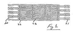
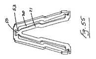
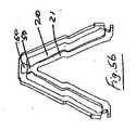
図面を参照して、本発明による様々な管腔人工器官が示される。管腔人工器官は、軸方向に配置され径方向に拡張可能な複数のステントセグメント22、23を備える。セグメント22、23は、セグメント22、23を連結する連結部分20、21を有する。セグメント22、23は、セグメント22、23の連結部分20、21が互いに係合された、たたまれた送達構成と、連結部分20、21が分離された展開構成との間で動くことができる。 Referring to the drawings, various luminal prostheses according to the present invention are shown. The luminal prosthesis includes a plurality of
連結部分は、雄型部分20および雌型部分21を備える。隣接するステントセグメント22、23の雄型部分20および雌型部分21は、たたまれた構成では互いに係合される。 The connecting portion includes a
ステントセグメント22、23が展開構成に近くなるまで連結部分の分離を遅らせる遅延手段を、雄型部分および/または雌型部分は備える。
雌型部分20は、隣接するステントセグメントの軸方向に延在する対応する雄型部分21を受ける入口30を有する軸方向に延在する通路を備える。遅延手段は、互いに係合可能な嵌合部を雄型部分および雌型部分に備える。嵌合部は、通路への入口30の内方へ軸方向に離れている。The male part and / or the female part are provided with delay means for delaying the separation of the connecting part until the
The
いくつかの実施形態では、通路に沿って軸方向に離れた第1嵌合部40、41および第2嵌合部50、51がある。好ましい実施形態では、第2嵌合部50、51は、入口から離れた通路30の端部に配置される(図18から図62)。 In some embodiments, there are first
第2嵌合部は、頭部部分50、および頭部部分50と係合する、対応するソケット部分51を備え得る。
ある場合では、ソケット部分は、頭部部分50に対して寸法が縮小されたネック部53を備える。雄型部分は、ソケットのネック部分に対応するネック部を有する。The second fitting portion may include a
In some cases, the socket portion includes a
頭部部分は、概ね球状の形状であり得るボール50を備え得る(図18から図26)。
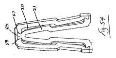
頭部部分50は、少なくとも1つの径方向に延在する突起を備え得る。好ましくは、頭部部分は、反対方向に向いた、径方向に延在する2つの突起54、55を備える。ある場合では、突起54、55は、対応するT形の雌型溝穴56の中に嵌って係合するように、T形の断面を形成する概ね直線形状のものである(図27から図53)。別の場合では、突起部分は概ね楔形57、58であり、結果として生じる頭部部分59は、対応する形状の雌型溝穴60と嵌って係合するように概ね台形の形のものである(図54から図58)。代替として、突起部分は、対応する形状の雌型溝穴63と嵌って係合するように概ね曲線形状61、62である(図59から図62)。The head portion can include a
The
本発明では、雄型部分および雌型部分は、好ましくは、拡張時に異なる変形および/または変位を受ける。いくつかの場合では、これら部分の一方が、有意な変位および/または拡張を受け、他方は受けない。 In the present invention, the male and female portions are preferably subjected to different deformations and / or displacements when expanded. In some cases, one of these portions will undergo significant displacement and / or expansion and the other will not.
本発明のステントは、解除可能に係合される複数の「ミニステント」を備える。言い換えると、縮められたとき、隣接するミニステントが互いに錠止して連続的な物体を形成し、それによって、拡張が開始したとき、ミニステントがバルーンの上に留まり、滑りにくくなることが可能となる。一定の直径に達したとき、ミニステントは、互いに分離し、共に作用する別々の物体として血管壁に接触する。したがって、一連のミニステントは血管壁に必要な支持を与える一方で、血管により大きい柔軟性をもたらす。このように柔軟性を増すことによって、現在の解決策の場合のような血管壁に対する、高い発生率の損傷を排除し、今日見られる、結果として起こる再狭窄のレベルを低減するはずである。 The stent of the present invention comprises a plurality of “mini-stents” that are releasably engaged. In other words, when contracted, adjacent mini-stents lock together to form a continuous object, so that when expansion begins, the mini-stent can stay on the balloon and become less slippery It becomes. When a constant diameter is reached, the mini-stent contacts the vessel wall as separate objects that separate from each other and act together. Thus, a series of mini-stents provide the necessary support to the vessel wall while providing greater flexibility to the vessel. This increased flexibility should eliminate the high incidence of damage to the vessel wall as in current solutions and reduce the level of resulting restenosis seen today.
このステントに考えられる主要な用途は末梢血管用であり、バルーン充気可能なステントは、その剛性が増すとこれらの非常に柔軟な血管に問題を引き起こすため、現在は、より大きい直径および長さではほとんど使用されない。その代わりに、自己拡張式のステントが一般に使用される。冠状血管の用途から、自己拡張式のステントは、旧来のバルーン充気式のものより、その部位における支持および信頼性が少ないことが知られており、埋入時の可制御性が低いことは言うまでもない。一般に、自己拡張式のステントは、介入心臓内科医の間で評判のよくない手段である。今日に至るまで、末梢血管における介入の開存率は、冠状血管における介入の開存率よりかなり低い。これは、末梢血管用ステントが、冠状血管用ステントと比べてかなり異なる機械的状態を受け、それによって、末梢血管用ステントが、損傷および疲労をかなり受けやすくなっているという事実に直接関連する。一般に、狭窄の生理学も異なる。全てのこれらの要因は、末梢血管の用途に優れた柔軟性および強度を要し、冠状血管用の解決策に基づいた構成を利用するのではなく、末梢血管の用途のために特に構成されるステントが要求される。故障率および介入医の好みの両方が主な要因である。 The main potential application for this stent is for peripheral vessels, and balloon-fillable stents now have problems with these very flexible vessels as their stiffness increases, so they are now of larger diameter and length Is rarely used. Instead, self-expanding stents are commonly used. From coronary vascular applications, self-expanding stents are known to have less support and reliability at the site than traditional balloon-filled stents and are less controllable when implanted. Needless to say. In general, self-expanding stents are an unpopular means among interventional cardiologists. To date, the patency rate of interventions in peripheral blood vessels is considerably lower than the patency rate of interventions in coronary vessels. This is directly related to the fact that peripheral vascular stents are subjected to significantly different mechanical states compared to coronary vascular stents, thereby making peripheral vascular stents much more susceptible to damage and fatigue. In general, the physiology of stenosis is also different. All these factors require excellent flexibility and strength for peripheral vascular applications and are specifically configured for peripheral vascular applications rather than utilizing configurations based on coronary solutions A stent is required. Both failure rate and interventionist preference are major factors.
さらに、本発明のステントは、また、心臓血管疾患の用途または任意の他の身体の管腔に、ステントの柔軟性が重要である場合において主に使用され得る。これらは、任意の動脈、静脈、食道、気管、結腸、胆管、または尿路を含むがこれに限定されない。 In addition, the stents of the present invention can also be used primarily in cardiovascular disease applications or any other body lumen where stent flexibility is important. These include, but are not limited to, any artery, vein, esophagus, trachea, colon, bile duct, or urinary tract.
バルーン充気可能な末梢血管用ステント留置術の解決策は、末梢血管における開存率を有意に改善し、また、血管介入医の間で評判のよい手段であることがわかるであろう。
本発明では、単一のバルーンから複数のステントを送達する手段として、拡張時に互いに分離することができる、剛性の閉じた小区画のステントセグメントを使用する。リングではなく、閉じた小区画のステントセグメントを構成することで、このような複数のステント留置術のシステムを開発することができた。ステント嵌合システムの構成および位置によって、ステントは縮められると堅く互錠されるが、拡張時には、ステントはゼロまたは最小の接触をもって互いに自由に関着できることが確実になる。隣接するステントセグメントの間の橋状または連接要素は、ステントの配置を達成するのに不可欠ではない。It will be appreciated that balloon-fillable peripheral vascular stenting solutions significantly improve patency in peripheral blood vessels and are a popular means among vascular interventionists.
The present invention uses a rigid closed sub-compartment stent segment that can be separated from each other upon expansion as a means of delivering multiple stents from a single balloon. Multiple stent placement systems could be developed by constructing closed, small compartment stent segments rather than rings. The configuration and position of the stent-fitting system ensures that the stents are tightly locked together when contracted, but when expanded, the stents can be freely engaged with each other with zero or minimal contact. Bridges or articulating elements between adjacent stent segments are not essential to achieve stent placement.
ステントは、血管または別のヒトもしくは動物の身体の管腔の壁を支持するように使用される、セグメントを形成するように連結された、管状で、径方向に拡張可能な複数のリングまたは支柱要素の組を備える機械的構造体である。本発明のステントの構造は、直線状、湾曲状、弓形、S形、Z形、V形、U形、またはループ状の要素の任意の組み合わせから成り立ち得る。これらの要素は、一連のセグメント、およびセグメントが構成する管の周囲のこれらのセグメントの間の最終的な連結を形成するようなやり方で連結される。セグメントが連結されるやり方は、一連の開いた小区画の構造体、閉じた小区画の構造体、または開いた小区画と閉じた小区画の組み合わせの構造体を形成し得る。 A stent is a tubular, radially expandable ring or strut connected to form a segment that is used to support a vessel or the wall of another human or animal body lumen. A mechanical structure comprising a set of elements. The structure of the stent of the present invention can consist of any combination of linear, curved, arcuate, S-shaped, Z-shaped, V-shaped, U-shaped, or loop-shaped elements. These elements are connected in such a way as to form a series of segments and a final connection between these segments around the tube that they constitute. The manner in which the segments are connected may form a series of open sub-compartment structures, closed sub-compartment structures, or a combination of open and closed sub-compartments.
本発明のステントの背後の基本的概念は、複数の複合セグメント(以後ミニステントと称される)からステントが成り立ち、これらのミニステントは、隣接するミニステントに物理的連接部によって連結されないことである。しかしながら、ミニステントは、縮められたときには隣接するミニステントと互錠し、拡張過程のより大きい直径にあるときには、ミニステントは分離し連結されないように構成される。ゆえに、ミニステントは、解除可能に係合される。この解除可能な係合は、いかなる橋状要素も使用することなく達成可能である。ここに示される場合では、隣接するミニステントが同じ面に配置されたとき、互錠が達成される。さらに、ステントを互錠させる嵌合システムは、拡張の後のステントの接触を最小にするように構成されている。 The basic concept behind the stent of the present invention is that a stent is composed of a plurality of composite segments (hereinafter referred to as mini-stents), and these mini-stents are not connected to adjacent mini-stents by physical connection. is there. However, a mini-stent is configured to interlock with an adjacent mini-stent when contracted, and to be separated and not connected when in a larger diameter during the expansion process. Hence, the mini-stent is releasably engaged. This releasable engagement can be achieved without the use of any bridge elements. In the case shown here, interlocking is achieved when adjacent mini-stents are placed on the same plane. Further, the mating system that interlocks the stent is configured to minimize contact of the stent after expansion.
したがって、縮められたとき、個別のセグメントが互いに互錠する。血管内で展開されたとき、このステントは、物理的に独立した一連の分離したミニステントとして働くが、血管壁に必要な支持を与える点において、単一のステントとして機能し続け、一方で、より大きい壁の柔軟性を与える。 Thus, when contracted, the individual segments lock together. When deployed within a blood vessel, this stent acts as a series of physically independent discrete mini-stents, but continues to function as a single stent in providing the necessary support to the vessel wall, while Gives greater wall flexibility.
バルーンの拡張の際には、ミニステントの互錠によって、展開過程の際に隣接するミニステントの間に一定の距離が確実に保持される。また、拡張の初期段階において、ステントは単一の物体として働くことが確実となり、無制御のステントの拡張(すなわちバルーン拡張式のステントの場合にはバルーン上でのステントの軸方向の動き)の問題に対抗する手段を提供する。 During balloon expansion, the mini-stents lock together to ensure that a certain distance is maintained between adjacent mini-stents during the deployment process. Also, in the initial stage of expansion, it is ensured that the stent acts as a single object, and uncontrolled expansion of the stent (ie, axial movement of the stent over the balloon in the case of a balloon expandable stent). Provide a means to counter the problem.
このステントの展開は、バルーンの拡張によって主に達成されるが、また、自己拡張によって、すなわち形状記憶材料の使用によっても達成可能である。ステントの展開は、単一のデバイスから達成され得る。自己拡張の場合、ミニステントは送達デバイスの使用によって展開される。 This deployment of the stent is mainly achieved by balloon expansion, but can also be achieved by self-expansion, ie by the use of shape memory materials. Stent deployment can be accomplished from a single device. In the case of self-expansion, the mini-stent is deployed through the use of a delivery device.
ステントの概念および構成の変形例は、図面に示される。ステントセグメントの嵌合に特に留意されたい。
本発明のステントは、解除可能に係合できる複数のセグメントを備える。この連結の仕組みは、いくつかの移動する空間を与え得る。連結がミニステントの一方にのみ必要な場合では、さらなる変更が可能である。いくつかの図は、ステント連結部の「切断」形状を示しており、これは、ステントが縮んだ後にステントがさらに互錠することを意味する。Variations on the concept and configuration of the stent are shown in the drawings. Of particular note is the fitting of the stent segments.
The stent of the present invention comprises a plurality of segments that can be releasably engaged. This coupling mechanism can provide several moving spaces. Further modifications are possible if the connection is only required for one of the mini-stents. Some figures show a “cut” shape of the stent connection, which means that the stent is more interlocked after the stent is contracted.
ステントは、たたまれた構成と拡張された構成との間で動くことができる。いくつかの図は、完全にはたたまれていない、本発明による様々なステントの切断された形態を示す。他の図は、完全にたたまれた形態の本発明による様々なステントを示す。ステントは、バルーン充気式であるか、または自己拡張式であり得る。 The stent can move between a collapsed configuration and an expanded configuration. Some figures show the cut forms of various stents according to the present invention that are not fully folded. Other figures show various stents according to the present invention in a fully collapsed form. The stent can be balloon-filled or self-expanding.
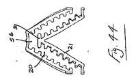
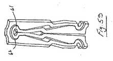
図1および2を参照すると、順応性の高い連結部を備えたステントが示される。ステントの小区画は、雄型部分21と雌型部分20とが互いに容易に嵌合するように構成される。雄型部分21は、雌型部分20の中に深くはめ込まれる。拡張時には、個々の小区画の動きは制限され、その結果、全体的なステントの縮小も最小になる。この構成は1つまたは複数の小区画を含むように修正され得ることが理解されるであろう。 With reference to FIGS. 1 and 2, a stent with a compliant connection is shown. The subsection of the stent is configured so that the
この場合、たたまれた構成において、雄型部分21は、雌型部分20の中に完全に延在して雌型部分20を満たす。
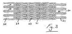
図3から図5は、代替の順応性の高い連結部を備えたステントを示す。この場合、雄型端部21は、嵌合を容易にするように先細になり、わずかに短くなっている。この修正は、雄型側21の様々な湾曲などを用いた複数のやり方で達成され得る。この場合、雄型部分21の先端部は、内方へ先細になっている。In this case, in the folded configuration, the
3 to 5 show a stent with an alternative highly compliant connection. In this case, the
ステントは、隣接する互錠セグメントを備えた単小区画のステントセグメントからなる単小区画の構成を有し得る。各セグメントは、第1組の支柱要素と、第2組の支柱要素と、第1組の支柱要素を第2組の支柱要素に連接する一組の連接要素とを備え得る。この構成の結果、閉じた小区画が、第1組の支柱要素の2つの支柱要素と、第2組の支柱要素の2つの支柱要素と、2つの連接要素との間に画定される。 The stent may have a single-compartment configuration consisting of single-compartment stent segments with adjacent interlocking segments. Each segment may comprise a first set of strut elements, a second set of strut elements, and a set of connecting elements that connect the first set of strut elements to the second set of strut elements. As a result of this configuration, a closed subsection is defined between the two strut elements of the first set of strut elements, the two strut elements of the second set of strut elements, and the two articulating elements.
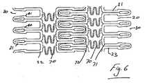
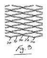
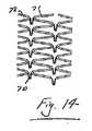
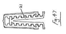
たたまれた送達構成と拡張された構成との間の動きに際してのステントセグメント22、22の縮小を補うために、ステントは、好ましくは、ステントセグメント22、23の支柱要素の間に非直線的に延在する連接要素70を組み込む。連接要素70は、任意の所望の形状および構成のものであり得る。図6では、連接要素70は概ねW形である。図6から図14に示されるステントの形状は、実例の目的のためのものである。ステントの形状は、図1から図5および図15から図62のいずれかに示されるような任意の適切な形状および構成のものであり得る。図7は、S形連接部70を備えた単小区画ステントを示す。これはステントがバルーン上で縮められるときに、同一の軌道を通ることを改善する。この場合、連接要素70は、支柱要素71よりもより柔軟である。図7に示すように、連接要素70は、第1組の支柱要素71と第2組の支柱要素72との間に、非直線的に、この場合では「S形状」に延在する。拡張時の連接要素の伸張は、連結要素によってもたらされるステントの遅れた分離によって容易になる。 To compensate for the shrinkage of the
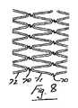
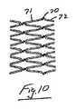
図8は、S形連接部70を備えた二倍小区画のステントを示す。図9は、S形連接部70を備えた三倍小区画のステントを示す。図10は、S形連接部70を備えた、単小区画と二倍小区画の組み合わせを有する別のステントを示す。ミニステントは、この図に示されるもののような様々な組み合わせで使用可能であり、ここでは、展開時に追加の剛性を与えるように、より長いミニステントが、ステント全体の各端部に配置される。 FIG. 8 shows a double-compartment stent with an S-shaped
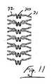
図11は、W形連接部70を備えた単小区画ステントを示す。これは、連接用支柱のさらなる変形例を提供する。この場合、連接要素70は、第1組の支柱要素71と第2組の支柱要素72との間に「W」形状に延在する。図12は、W形連接部70を備えた、二倍小区画ステントを示す。 FIG. 11 shows a single-compartment stent with a W-shaped
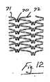
図13は、修正されたS形連接部70を備えた単小区画ステントを示す。これは、連接用支柱のさらなる変形例である。この場合、連接要素70は、第1組の支柱要素71と第2組の支柱要素72との間に「M」形状に延在する。 FIG. 13 shows a single-compartment stent with a modified S-shaped
図14は、V形連接部70を備えた二倍小区画ステントを示す。これは、連接用支柱のさらなる変形例である。連接部の位置を動かすことで、拡張時にミニステントが分離するときを制御することを容易にする。この場合、連接要素70は、第1組の支柱要素71と第2組の支柱要素72との間に「V」形状に延在する。 FIG. 14 shows a double-compartment stent with a V-shaped
本発明は、拡張過程の間に一定の最小直径に達したときのみに分離する、互錠するステントを提供する。ステント嵌合システムの構成および位置によって、縮められたときステントは堅く互錠されるが、拡張時には、ステントはゼロまたは最小の接触を有して互いに自由に関着できることが確実となる。セグメントの早期の分離は、拡張時のセグメントの回転ならびに長さ方向の変位を引き起こし得る。早期の分離は、また、縮小を最小にするために、拡張時に連接要素がまっすぐになることを妨げ得る。 The present invention provides an interlocking stent that separates only when a certain minimum diameter is reached during the expansion process. The configuration and position of the stent mating system ensures that the stents are tightly locked together when contracted, but when expanded, the stents can be freely engaged with each other with zero or minimal contact. Early separation of the segments can cause segment rotation as well as displacement in length. Early separation may also prevent the articulating elements from straightening when expanded to minimize shrinkage.
それぞれの錠部は、雌型部分20および雄型部分21を含む。雄型部分21は、雌型部分20によって囲まれる。このような最初互錠しているステントの拡張時における分離は、雌型部分20が、雄型部分を解除するのに十分に大きい開口部をもたらすように広がったとき、または、雄型構成要素が雌型部分20の中を通過することができるように拡張時に雄型構成要素が縮んだ場合のみに起こる。拡張時に、互錠しているステントの分離が起こる点は、拡張時の雌型および雄型構成要素20、21の相対的な変位および/または変形を制御することによって制御可能である。 Each lock includes a
図1から図6および図15から図17のステントでは、ステントの分離の制御は、雄型部分21と雌型部分20の高さの比、および嵌合システムの雄型部分21と雌型部分20の幅の比を変えることによって達成される。比を増すことによって、分離を遅らせることが可能である。しかしながら、どれだけ増すことができるかについての物理的な限界がある。たとえば、雄型構成要素21は雌型構成要素によって拘束されるので、雄型構成要素21の高さが大きすぎると、雄型構成要素21は、ステントを縮める際に正常に伸びることができない。さらに、雄型構成要素21および雌型構成要素20が縮められた構成に従いすぎると、雄型部分21は、拡張時に開く際に、雌型部分20を長さ方向に押す傾向があり、それが、ステントの送達の際に制御を低減する一因となり得る。 In the stents of FIGS. 1-6 and 15-17, the separation control of the stent is controlled by the height ratio of the
図18から図26のステントでは、雄型部分50は、拡張時に最小の変形を受けるように構成される。したがって、雌型部分51の開口部が、雄型構成要素50の頭部の直径より大きい長さまで移動または変形すると、分離が起こる。ステントは、ステントが有意に径方向に拡張したときのみにこれが起こることを確実にするように構成されている。これは、拡張時に、比較的小さい変位/変形を受けるステントの領域に雌型部分51を配置することによって達成される。このステントシステムは、図1から図17のステントより拡張時にかなり遅く分離し、したがって、個々のステントがバルーンに沿って長さ方向に動く危険性、または拡張時にステントが回転する危険性(すなわち無制御の送達)が制限される。雄型構成要素50が拡張時に有意に移動または変形しない場合、あるセグメントが別のセグメントによって押される(弾き飛ばされる)危険性が最小になる。 In the stent of FIGS. 18-26, the
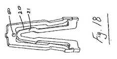
図18から図21は、2つのステントセグメントの係合を示す。2つのタイプの連結部が関係する。図15から図17の連結部は、拡張時にセグメントを互いにより少なく押すように修正されている。第2の連結システムは、固定された雄型50、雌型部分20の変形の少ない端部に嵌合するように配置される柔軟な雌型51である。 18-21 show the engagement of two stent segments. Two types of connections are involved. The connections of FIGS. 15-17 have been modified to push the segments less together when expanded. The second connection system is a flexible
図19は、初めの拡張の後、連結システム40、41は解除されるが、二次嵌合システム50、51は依然として連結されているのを示す。
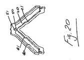
二次嵌合システム50、51は、図20に示すように、完全な展開に近い、より大きい直径になったときにのみ分離される。遅延の量は、雄型部分50の直径とネック部の幅の比を変え、それに対応して雌型部分51を変化させることによって制御可能である。FIG. 19 shows that after the initial expansion, the
The
図21は、最終の展開された構成を示す。嵌合システムは分離されている。分離の後、ステントの動きは、バルーンによって制御される。
図22は、上述の嵌合システムを含むセグメント全体を示す。二次嵌合システム50、51は、雄型部分との分離を遅らせるために、ステントの他の領域と比較して雌型部分が比較的小さい変位を受けるように配置される。遅れた分離は、個々のステントが拡張時に単一のユニットとして働くことを確実にし、送達時に1つまたは複数のステントセグメントの無制御の動きを防ぐ。制御を強化するために、雌型部分51の縁部は雄型部分50のネック部の近くにある。雌型部分51は、ステントの静止部分であり、したがって、雄型部分50によって強制的に開かれるのではなく、ステントの変形によって開く。この特徴がない場合、分離は、雄型部分が雌型部分に対して送達デバイスに沿って長さ方向に変位するために起こり得る。このような状況では、雄型部分によって雌型部分にかけられる力が、雌型部分を強制的に開き、その結果、隣接するステントが無制御に動くおよび/または分離する可能性がある。すでに述べたように、示されたステント嵌合システムにおいては、雌型部分はステントの径方向の変形によって広がる。本発明の互錠システムでは、分離はステントの径方向の拡張の程度によって制御される。これは特に重要で有利な態様である。FIG. 21 shows the final deployed configuration. The mating system is separated. After separation, stent movement is controlled by a balloon.
FIG. 22 shows the entire segment including the fitting system described above. The
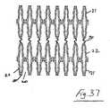
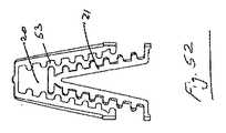
図23は、重なりのないセグメントのための嵌合システムを有するミニステントのセグメントを示す。嵌合システムは、図18から図22のシステムと同じである。上述のように連接要素70がある。3つのセグメントの係合が図24に示される。 FIG. 23 shows a mini-stent segment with a mating system for non-overlapping segments. The mating system is the same as the system of FIGS. There is a connecting
図25は、図22と同じ嵌合システムを備えた二倍の小区画サイズである。二倍の小区画サイズは、動脈内に配置されたとき、異なる負荷の下でミニステントがひっくり返るのを回避する助けとなる。これら間の連接部70は異なる形状であり得る。互錠システムと結合された相互連接部70は、セグメントの縮小を低減する。嵌合システムによって互錠するステントの分離を遅らせることで、送達デバイスに沿ったステントの無制御の軸方向の動きを防ぐことによって、相互連接部は、圧縮するのではなく確実にまっすぐになる。 FIG. 25 is a double parcel size with the same mating system as FIG. The double subcompartment size helps to avoid overturning the mini-stent under different loads when placed in an artery. The connecting
雄型部分50の形状を変えることによって、分離はさらに遅らせることができる。図27から図37を参照すると、「T」形の雄型構成要素50は、拡張時に比較的小さい変位および変形を受ける場合に、分離を確実に遅らせる。遅延は、「T」の頂部の長さと「T」のネック部の厚さの比によって制御され得る。円形の互錠部と比較して、「T」形の互錠部を使用するとより大きい遅延が達成可能であるが、雄型構成要素は、分離の前により大きい変形を受け得る。「T」の頂部が拡張時に無理に「V」または「U」の形状をとらされる場合、これは、早期の分離につながる。 By changing the shape of the
図27から図30は、2つの異なる連結システムを有する2つのセグメントの2つの小区画の係合を示す。第2の連結システム50、56は、T形状の連結システムである。図18から図26の円形の嵌合システムと同様に、より多くの遅延がもたらされる。T形状の錠部は、円形の形状よりの多くの遅延制御を与えることができる。セグメント全体が図31に示される。導入された嵌合システムはセグメントの対称性を保持することに留意されよう。拡張およびはね返りの後、均等な変形をもたらすために、ミニステントが対称性を有することが重要である。 Figures 27 to 30 show the engagement of two subsections of two segments with two different connection systems. The
図27は、両方の連結システムが依然として係合している部分的な拡張時の2つのセグメントの2つの小区画の係合を示す。
図28は、第1連結システム40、41の分離を示す。この場合、雄型部分21は、雌型部分20と同様に開く。分離時には、雄型部分21の外側の幅は、雌型部分20の内側の幅より小さい。FIG. 27 shows the engagement of the two subsections of the two segments during partial expansion when both connection systems are still engaged.
FIG. 28 shows the separation of the
図29は、二次連結システム50、51の分離を示す。これは、第1連結システム40、41の分離の後に起こる。分離時には、雌型部分は、T50の頭部部分の幅と等しいか、またはそれより大きいサイズにまで開く。 FIG. 29 shows the separation of the
図30は、完全な分離の後の部分的な拡張を表す。
図31は、T形状の嵌合システムを含むセグメントを示す。
7つのセグメントの係合が図32に示される。FIG. 30 represents the partial expansion after complete separation.
FIG. 31 shows a segment including a T-shaped fitting system.
The engagement of the seven segments is shown in FIG.
図33から図37は、異なるタイプの相互連接部を備えた二倍サイズのセグメントにおける嵌合システムを示す。二倍小区画セグメントの間の相互連接部が、縮小を少なくし、また、ステントのより長い長さが、ステントがひっくり返る危険性を少なくする。 Figures 33 to 37 show a mating system in a double sized segment with different types of interconnections. The interconnection between the two-fold compartment segments reduces shrinkage and the longer length of the stent reduces the risk of the stent tipping over.
図33は、相互連接部を備えない二倍小区画セグメントである。しかしながら、単一小区画セグメントと比較して、展開の後の長さがより長くなり得る。
図34は、U形の相互連接部70を用いる二倍小区画セグメントである。この相互連接部は、縮小を少なくする。FIG. 33 is a double-compartment segment without an interconnect. However, the length after deployment can be longer compared to a single parcel segment.
FIG. 34 is a double-compartment segment using a
図35および図36は、部分的な相互連接部を備えた二倍小区画セグメントである。これは図34のステントと比較してより柔軟である。
図37は、S形の相互連接部70を備えた二倍サイズの小区画である。S形の相互連接部は、U形の相互連接部よりも縮小の制御がより増強され得る。Figures 35 and 36 are double-compartment segments with partial interconnections. This is more flexible compared to the stent of FIG.
FIG. 37 is a double sized subdivision with an S-shaped interconnecting
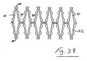
図38から図62は、1つのステントにおける複数の嵌合システムを示す。このシステムでは、必要とされる遅延次第で、雄型部分は、異なる雌型部分と係合され得る。分離の最も長い遅延を得るためには、雄型部分は、通路30の端部に最も近い最後の雌型部分と係合され得る。第1の雌型構成要素は、変形が大きいために最も早く分離する。分離の所望の遅延が、こうして選択され得る。 38-62 show multiple mating systems on one stent. In this system, depending on the required delay, the male part can be engaged with a different female part. In order to obtain the longest delay in separation, the male part can be engaged with the last female part closest to the end of the
図38から図40を参照すると、ステントの長さに沿って配置される複数の雌型構成要素80を備えたステントセグメントが示される。このようにして、異なる雌型部分の中にステントの雄型部分を縮め入れることによって分離が制御可能である。ステントのベース部に形成される雌型構成要素に、雄型構成要素を(ステントの頂点で)縮め入れることよって、ステントの分離が遅れさせられる。 Referring to FIGS. 38-40, a stent segment with a plurality of female components 80 disposed along the length of the stent is shown. In this way, separation can be controlled by shrinking the male part of the stent into different female parts. By retracting the male component (at the apex of the stent) into the female component formed in the base of the stent, the separation of the stent is delayed.
図38は、2つの雌型構成要素および1つの雄型構成要素を備えた嵌合システムを示す。雄型構成要素は、それぞれの雌型構成要素と係合され得るが、内側の雌型部分は、より多くの遅延をもたらし、より早期の分離が必要とされる場合、最も外側の部分が使用され得る。 FIG. 38 shows a mating system with two female components and one male component. The male component can be engaged with the respective female component, but the inner female part provides more delay and the outermost part is used when earlier separation is required Can be done.
図39は、切断した構成の図38のセグメントの係合を示す。分離時に最も多くの遅延をもたらすように、雄型部分が内側の雌型部分と係合されている。
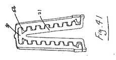
図41から図44を参照すると、縮める際に、2つの隣接する半球が接触したときに、形成された雌型部分80の1つに、同じ雄型構成要素を縮め入れることによって、より早期の分離が達成可能である。これはまた、複数のステントの分離が遅れさせられるべきである場合、確実に雌型部分80が変位の少ない領域にあるようにステントを構成する重要性を示す。FIG. 39 shows the engagement of the segments of FIG. 38 in the cut configuration. The male part is engaged with the inner female part to provide the most delay during separation.
Referring to FIGS. 41-44, when shrinking, when two adjacent hemispheres come into contact, one of the formed female parts 80 is shrunk into the earlier male component 80 by shrinking the same male component. Separation can be achieved. This also shows the importance of configuring the stent to ensure that the female portion 80 is in a region of low displacement when the separation of multiple stents should be delayed.
図40は、図38の段階制御を含む二倍小区画セグメントである。セグメントの間の相互連接部70が縮小を低減する。
図41は、縮められた構成の2つの複数の雌型部分を有するセグメントの係合を示す。FIG. 40 is a double compartment segment that includes the step control of FIG.
FIG. 41 shows the engagement of a segment having two female portions in a contracted configuration.
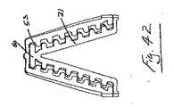
図42は、図41のセグメントの部分的な拡張である。
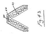
図43は、雄型構成要素と雌型構成要素の分離を示す。
図44は、分離の後の図43のセグメントの部分的な拡張である。FIG. 42 is a partial extension of the segment of FIG.
FIG. 43 shows the separation of the male and female components.
FIG. 44 is a partial expansion of the segment of FIG. 43 after separation.
図45は、複数の雌型部分を含む切断した構成のステントのセグメントである。
図46は、切断した構成の複数の雌型構成要素を有するセグメントの係合の例である。
図47は、雄型部分が第2の雌型部分と係合されたときの複数の雌型構成要素を有するステントの縮められたセグメントの詳細図である。分離は図41のステントよりも早く起こる。FIG. 45 is a segment of a stent in a cut configuration that includes a plurality of female mold portions.
FIG. 46 is an example of engagement of a segment having a plurality of female components in a cut configuration.
FIG. 47 is a detailed view of a crimped segment of a stent having a plurality of female components when the male portion is engaged with the second female portion. Separation occurs faster than the stent of FIG.
図48は、分離の前のステントの部分的な拡張を示す。
図49は、嵌合システムの分離時の部分的な拡張を示す。
図50は、分離の後の拡張した構成である。FIG. 48 shows partial expansion of the stent prior to separation.
FIG. 49 shows a partial expansion upon separation of the mating system.
FIG. 50 shows the expanded configuration after separation.
図51から53は、複数の雌型構成要素を有するステントの縮められた状態および部分的な拡張状態を示す。雄型部分は、上述のように、より早期に分離するように第3の雌型部分と係合される。 FIGS. 51-53 show a collapsed and partially expanded state of a stent having a plurality of female components. The male part is engaged with the third female part for earlier separation as described above.
図54から図58を参照して、別の変形例は、台形の雄型構成要素である。このステント構成の雄型部分は、拡張時に、「T」構成の雄型部分と比較して、より少ない変形を受ける。 Referring to FIGS. 54 to 58, another variation is a trapezoidal male component. The male part of this stent configuration undergoes less deformation when expanded compared to the male part of the “T” configuration.
図54は、ステントの2つのセグメントの部分的な拡張を示す。ステントは、2つの異なる連結システムを含む。第1の柔軟な連結システムのステント、および固定された雄型と柔軟な雌型のステントである第2の嵌合システムである。 FIG. 54 shows the partial expansion of the two segments of the stent. The stent includes two different connection systems. A first flexible coupling system stent and a second mating system that is a fixed male and flexible female stent.
図55は、第1連結システムの分離を表す。
図56は、ステントの拡大された直径のところの二次嵌合システムの分離を示す。台形のより長い底辺よりも雌型部分が広がると、分離が起こる。この二次嵌合システムが、分離を制御する。この段階で、バルーンはステントの回転および軸方向の動きを防ぐために十分に充気される。FIG. 55 represents the separation of the first coupling system.
FIG. 56 shows the separation of the secondary mating system at the enlarged diameter of the stent. Separation occurs when the female part extends beyond the longer base of the trapezoid. This secondary mating system controls the separation. At this stage, the balloon is sufficiently filled to prevent stent rotation and axial movement.
図57は、二次嵌合システムの分離の後の部分的に拡張したステントである。
図58は、台形の互錠システムを有するセグメントを示す。各セグメントは、雄型ならびに雌型を含む。FIG. 57 is a partially expanded stent after separation of the secondary mating system.
FIG. 58 shows a segment having a trapezoidal interlocking system. Each segment includes a male type as well as a female type.
図54から図62の構成の変形例では、拡張時に分離が起こる点は、雄型部分のネック部に対する雄型部分の頭部の幅および雌型部分の開口部を増減することによってさらに制御可能である。 54-62, the point at which separation occurs during expansion can be further controlled by increasing or decreasing the width of the head of the male part relative to the neck of the male part and the opening of the female part. It is.
図59から図62にたとえば示されるように、雄型構成要素も、拡張時に広がるように構成され、したがって、雌型構成要素が分離の前に受けなければならない拡張の量も増加しなければならないので、分離は遅れる。 As shown for example in FIGS. 59-62, the male component is also configured to expand upon expansion, and therefore the amount of expansion that the female component must undergo prior to separation must also be increased. So the separation is delayed.
図59は、縮められた構成の元の互錠システムおよび追加の柔軟な互錠システムを有するステントの2つのセグメントの係合を示す。
図60は、第1互錠システムが分離されている一方で、二次嵌合システムが依然として係合されているのを示す。FIG. 59 shows the engagement of two segments of a stent with the original interlocking system in a contracted configuration and an additional flexible interlocking system.
FIG. 60 shows that the first interlocking system is separated while the secondary mating system is still engaged.
図61は、二次嵌合システムが分離されたときのステントのセグメントである。
図62は、セグメントの分離の後のステントの部分的な拡張である。固定された雄型/柔軟な雌型としての同じ構成と比較して、より多くの遅延が達成可能である。FIG. 61 is a segment of the stent when the secondary mating system is separated.
FIG. 62 is a partial expansion of the stent after segment separation. More delay can be achieved compared to the same configuration as a fixed male / flexible female.
上述の構成のいずれも、ステントの全長を増すように、二倍小区画セグメントを作製することまたはより長い小区画を作製することによって変更可能である。これは、動脈内への送達の後にステントが「ひっくり返る」のを防ぐのに必要となり得る。セグメントの長さの最適範囲は、ステントがひっくり返るのを防ぎ、また、ステント全体の柔軟性を保つことができるものである。 Any of the above-described configurations can be modified by creating double-compartment segments or by creating longer compartments to increase the overall length of the stent. This may be necessary to prevent the stent from “turning over” after delivery into the artery. The optimal range of segment lengths is one that prevents the stent from tipping over and maintains the overall flexibility of the stent.
本発明では、ステントセグメントの径方向の有意な拡張が達成されるまで、2つのステントセグメントの切り離しは起こらない。連結システムの雄型部分および雌型部分は、非常に順応性がある。したがって、ステントの径方向の拡張が起こり、雌型部分によって与えられる開口部が、雄型部分の外径より大きくなるまで、両方向(たとえばバルーンまたは送達システムの上または下)の軸方向の連結が隣接するステントの間に保持される。ステントセグメントの拡張が起こると、かなりの縮小が起こる(たとえば図15から図17)。したがって、複数のステントを送達するときのこのような縮小を防ぐために、拡張時に伸長する連接要素が、好ましくはステントの構成に組み込まれるべきである。 In the present invention, the separation of the two stent segments does not occur until a significant radial expansion of the stent segments is achieved. The male and female parts of the connection system are very compliant. Thus, axial expansion in both directions (eg above or below the balloon or delivery system) is achieved until radial expansion of the stent occurs and the opening provided by the female part is greater than the outer diameter of the male part. It is held between adjacent stents. When stent segment expansion occurs, significant shrinkage occurs (eg, FIGS. 15-17). Accordingly, articulating elements that expand upon expansion should preferably be incorporated into the stent configuration to prevent such shrinkage when delivering multiple stents.
本発明では、隣接するステントセグメントの分離をさらに遅らせるために、拡張時に比較的小さい変位を受ける領域に嵌合システムが配置され、これによって、拡張過程の後期まで、ステントセグメントの間の軸方向の連結を確保する(図18〜図21および図27〜図30を参照)。本発明では、嵌合システムは、変位の少ない領域に配置され、それは、隣接するステントを実質的に挟み合わせることによって達成される。嵌合システムは、ステントの端部ではなく本体に配置される。これを達成するために、ステントは、たたまれた構成において互いに実質的に挟み合わさる/食い込む。この利点は、ステントが、広がった後も依然として挟み合わさっており、それによって、血管壁の支持がより大きくなることである。本発明では、隣接するステントは、嵌合システムの遅れた切り離しが起こるように、実質的に挟み合わさる。さらに、本発明で使用される嵌合システムの順応性のある性質が、実質的に、隣接するステントが正または負の軸方向に相対的に動くのを防ぐ。 In the present invention, to further delay the separation of adjacent stent segments, a mating system is placed in a region that undergoes a relatively small displacement during expansion, thereby allowing axial alignment between the stent segments until later in the expansion process. The connection is secured (see FIGS. 18 to 21 and FIGS. 27 to 30). In the present invention, the mating system is placed in a low displacement area, which is achieved by substantially sandwiching adjacent stents. The mating system is placed on the body, not on the end of the stent. To accomplish this, the stents are substantially sandwiched / engraved with each other in the collapsed configuration. The advantage is that the stent is still sandwiched after it has expanded, thereby providing greater support for the vessel wall. In the present invention, adjacent stents are substantially pinched so that delayed detachment of the mating system occurs. Further, the compliant nature of the mating system used in the present invention substantially prevents adjacent stents from moving relative to the positive or negative axial direction.
本発明では、隣接するステントの間に2つの連結部が存在し、1つは、互いの周囲にたたまれたときにステント本体によって形成され、第2は、ステントの端部に形成される。ステント本体は、適度に順応性のあるように構成され、それによって、ステントが縮められる/たたまれる際に、ステント本体が、各ステント本体の端部の嵌合システムの雄型部分を隣接するステントの対応する雌型構成要素の中へ案内する。 In the present invention, there are two connections between adjacent stents, one formed by the stent body when folded around each other and the second formed at the end of the stent. . The stent body is configured to be reasonably compliant so that the stent body abuts the male portion of the mating system at the end of each stent body as the stent is contracted / folded. Guide into the corresponding female component of the stent.
本発明は、増殖を抑制する生物活性物質と併せて、その放出を制御する被覆および化合物とともに使用され得る。生物活性物質は、抗新生物薬、抗生物質、免疫抑制薬、酸化窒素源、エストロゲン、およびエストラジオールを含み得るが、これに限定されない。 The present invention can be used with coatings and compounds that control its release in conjunction with bioactive agents that inhibit growth. Bioactive agents can include, but are not limited to, anti-neoplastic agents, antibiotics, immunosuppressants, nitric oxide sources, estrogens, and estradiol.
ステントは、複数の金属および重合体材料、また、生物分解性の化合物および管腔内での展開後に時間とともに分解する他の材料から製造され得る。
ステントの構成は、明確な位置にX線不透過性の標識を作製するように変更可能であり、すなわち、金または任意の他のX線不透過性の材料などの材料を含むように、要素が変更されるか、追加の要素が加えられてもよい。Stents can be made from a plurality of metal and polymeric materials, as well as biodegradable compounds and other materials that degrade over time after deployment in the lumen.
The configuration of the stent can be modified to create radiopaque labels at well-defined locations, i.e. include materials such as gold or any other radiopaque material. May be changed or additional elements may be added.
ステントの機械的な挙動をよりよく制御するために、個々の要素の相対的な寸法が、単一のミニステントの中で、または異なるミニステントの対応する要素の間で変わってもよい。たとえば、ステントの外側のミニステントのいくつかの要素は、ステントの中央のミニステントの対応する要素より厚くてもよい。 To better control the mechanical behavior of the stent, the relative dimensions of the individual elements may vary within a single mini-stent or between corresponding elements of different mini-stents. For example, some elements of the mini-stent outside the stent may be thicker than the corresponding elements of the central mini-stent of the stent.
本発明は、添付の図面を参照して上述された実施形態に限定されず、構造および詳細において変更されてもよい。 The invention is not limited to the embodiments described above with reference to the accompanying drawings, but may be varied in structure and detail.
Claims (53)
Translated fromJapanese前記セグメントが、前記セグメントを連結する連結部分を有し、
前記セグメントが、前記セグメントの前記連結部分が互いに係合された、たたまれた送達構成と、前記連結部分が分離された展開構成と、の間で動くことができ、
前記ステントセグメントが、前記ステントセグメントが前記展開構成に近くなるまで前記連結部分の分離を遅らせる手段を有する、
人工器官。In a luminal prosthesis comprising a plurality of axially arranged and radially expandable stent segments,
The segment has a connecting portion connecting the segments;
The segment can move between a collapsed delivery configuration in which the connecting portions of the segment are engaged with each other and a deployed configuration in which the connecting portions are separated;
The stent segment comprises means for delaying separation of the connecting portion until the stent segment is close to the deployed configuration;
Prosthesis.
前記セグメントが、前記セグメントを連結する連結部分を有し、
前記セグメントが、前記セグメントの前記連結部分が互いに係合された、たたまれた送達構成と、前記連結部分が分離された展開構成と、の間で動くことができ、
前記セグメントが、第1組の支柱要素と、第2組の支柱要素と、前記第1組の支柱要素の少なくともいくつかを前記第2組の支柱要素の少なくともいくつかに連接する第1組の1つまたは複数の連接要素と、を備え、前記連接要素が前記支柱要素よりも柔軟である、
人工器官。In an endoprosthesis comprising a plurality of axially arranged and radially expandable stent segments,
The segment has a connecting portion connecting the segments;
The segment can move between a collapsed delivery configuration in which the connecting portions of the segment are engaged with each other and a deployed configuration in which the connecting portions are separated;
A first set of strut elements, a second set of strut elements, and a first set of strut elements connecting at least some of the first set of strut elements to at least some of the second set of strut elements. One or more articulating elements, the articulating elements being more flexible than the strut elements,
Prosthesis.
送達カテーテルの上に軸方向に配置された、径方向に拡張可能な複数のステントセグメントを備えた前記送達カテーテルを用意するステップであって、前記ステントセグメントが、互いに係合された連結部分を有するステップと、
前記カテーテルを処置部位に送達するステップと、
前記処置部位にある全ての前記ステントセグメントを、前記セグメントの前記連結部分が互いに係合した状態に留まる、部分的に拡張した構成まで径方向に拡張するステップと、
全ての前記ステントセグメントを、前記ステントセグメントの全ての前記連結部分が分離される展開構成までさらに径方向に拡張するステップと、
を含む方法。In a method of delivering a luminal prosthesis to a treatment site,
Providing the delivery catheter with a plurality of radially expandable stent segments axially disposed on the delivery catheter, the stent segments having interlocking portions engaged with each other; Steps,
Delivering the catheter to a treatment site;
Radially expanding all of the stent segments at the treatment site to a partially expanded configuration where the connecting portions of the segments remain engaged with each other;
Further radially expanding all the stent segments to a deployed configuration in which all the connecting portions of the stent segments are separated;
Including methods.
Applications Claiming Priority (2)
| Application Number | Priority Date | Filing Date | Title |
|---|---|---|---|
| US99664607P | 2007-11-28 | 2007-11-28 | |
| PCT/IE2008/000116WO2009069113A1 (en) | 2007-11-28 | 2008-11-28 | A luminal prosthesis |
Publications (2)
| Publication Number | Publication Date |
|---|---|
| JP2011504780Atrue JP2011504780A (en) | 2011-02-17 |
| JP2011504780A5 JP2011504780A5 (en) | 2012-01-19 |
Family
ID=40276021
Family Applications (1)
| Application Number | Title | Priority Date | Filing Date |
|---|---|---|---|
| JP2010535505APendingJP2011504780A (en) | 2007-11-28 | 2008-11-28 | Lumen prosthesis |
Country Status (4)
| Country | Link |
|---|---|
| US (1) | US20110190861A1 (en) |
| EP (1) | EP2229127A1 (en) |
| JP (1) | JP2011504780A (en) |
| WO (1) | WO2009069113A1 (en) |
Cited By (1)
| Publication number | Priority date | Publication date | Assignee | Title |
|---|---|---|---|---|
| JP2015529102A (en)* | 2012-08-13 | 2015-10-05 | アボット カルディオバスキュラー システムズ インコーポレーテッドAbbott Cardiovascular Systems Inc. | Segmented scaffold structure |
Families Citing this family (10)
| Publication number | Priority date | Publication date | Assignee | Title |
|---|---|---|---|---|
| US6814746B2 (en)* | 2002-11-01 | 2004-11-09 | Ev3 Peripheral, Inc. | Implant delivery system with marker interlock |
| US8574283B1 (en)* | 2011-08-30 | 2013-11-05 | Suraj Govind Kamat | Deployment of stents within bifurcated vessels |
| EP2799036A1 (en)* | 2013-04-02 | 2014-11-05 | Biotronik AG | Intraluminal endoprosthesis and method for production thereof |
| CN105769398B (en)* | 2016-03-18 | 2017-09-29 | 上海工程技术大学 | Biodegradable vascular scaffold based on polyhedron deformation mechanism |
| US11622872B2 (en) | 2016-05-16 | 2023-04-11 | Elixir Medical Corporation | Uncaging stent |
| JP6963566B2 (en)* | 2016-05-16 | 2021-11-10 | エリクシアー メディカル コーポレイション | Uncaging stent |
| US10231856B2 (en) | 2016-10-27 | 2019-03-19 | Cook Medical Technologies Llc | Stent with segments capable of uncoupling during expansion |
| US10842654B2 (en)* | 2017-07-19 | 2020-11-24 | Cook Medical Technologies Llc | Stent with segments capable of uncoupling during expansion |
| US11389312B2 (en) | 2018-01-16 | 2022-07-19 | Sintra Medical Llc | Stents with increased flexibility |
| EP3998987B1 (en) | 2019-07-16 | 2024-10-09 | Sintra Medical Llc | Stents with increased flexibility |
Citations (7)
| Publication number | Priority date | Publication date | Assignee | Title |
|---|---|---|---|---|
| US20020111671A1 (en)* | 2001-02-15 | 2002-08-15 | Stenzel Eric B. | Locking stent |
| JP2003047662A (en)* | 2001-06-08 | 2003-02-18 | Cordis Corp | Blood vessel extension device and method |
| JP2004329790A (en)* | 2003-05-12 | 2004-11-25 | Nipro Corp | Flexible stent which is excellent in vascular follow-up nature and lumen diameter holding nature |
| JP2005118572A (en)* | 2003-10-17 | 2005-05-12 | Cordis Corp | Stent design having independent stent segment which uncouple upon deployment |
| US20060069424A1 (en)* | 2004-09-27 | 2006-03-30 | Xtent, Inc. | Self-constrained segmented stents and methods for their deployment |
| US20060195175A1 (en)* | 2005-02-25 | 2006-08-31 | Abbott Laboratories Vascular Enterprises Limited | Modular vascular prosthesis having axially variable properties and improved flexibility and methods of use |
| WO2007117960A2 (en)* | 2006-03-31 | 2007-10-18 | St. Jude Medical, Cardiology Division, Inc. | Stent and system and method for deploying a stent |
Family Cites Families (5)
| Publication number | Priority date | Publication date | Assignee | Title |
|---|---|---|---|---|
| AU6144599A (en)* | 1998-09-16 | 2000-04-03 | Isostent, Inc. | Linkage stent |
| FR2795576B1 (en) | 1999-06-28 | 2007-01-05 | Centre Nat Etd Spatiales | SYSTEM COMPRISING A RADIO FREQUENCY ANTENNA SATELLITE |
| GB0121980D0 (en) | 2001-09-11 | 2001-10-31 | Cathnet Science Holding As | Expandable stent |
| US7163553B2 (en)* | 2001-12-28 | 2007-01-16 | Advanced Cardiovascular Systems, Inc. | Intravascular stent and method of use |
| WO2007134290A2 (en) | 2006-05-12 | 2007-11-22 | Ev3, Inc. | Implant and delivery system with multiple marker interlocks |
- 2008
- 2008-11-28WOPCT/IE2008/000116patent/WO2009069113A1/enactiveApplication Filing
- 2008-11-28JPJP2010535505Apatent/JP2011504780A/enactivePending
- 2008-11-28USUS12/734,818patent/US20110190861A1/ennot_activeAbandoned
- 2008-11-28EPEP08853977Apatent/EP2229127A1/ennot_activeWithdrawn
Patent Citations (7)
| Publication number | Priority date | Publication date | Assignee | Title |
|---|---|---|---|---|
| US20020111671A1 (en)* | 2001-02-15 | 2002-08-15 | Stenzel Eric B. | Locking stent |
| JP2003047662A (en)* | 2001-06-08 | 2003-02-18 | Cordis Corp | Blood vessel extension device and method |
| JP2004329790A (en)* | 2003-05-12 | 2004-11-25 | Nipro Corp | Flexible stent which is excellent in vascular follow-up nature and lumen diameter holding nature |
| JP2005118572A (en)* | 2003-10-17 | 2005-05-12 | Cordis Corp | Stent design having independent stent segment which uncouple upon deployment |
| US20060069424A1 (en)* | 2004-09-27 | 2006-03-30 | Xtent, Inc. | Self-constrained segmented stents and methods for their deployment |
| US20060195175A1 (en)* | 2005-02-25 | 2006-08-31 | Abbott Laboratories Vascular Enterprises Limited | Modular vascular prosthesis having axially variable properties and improved flexibility and methods of use |
| WO2007117960A2 (en)* | 2006-03-31 | 2007-10-18 | St. Jude Medical, Cardiology Division, Inc. | Stent and system and method for deploying a stent |
Cited By (1)
| Publication number | Priority date | Publication date | Assignee | Title |
|---|---|---|---|---|
| JP2015529102A (en)* | 2012-08-13 | 2015-10-05 | アボット カルディオバスキュラー システムズ インコーポレーテッドAbbott Cardiovascular Systems Inc. | Segmented scaffold structure |
Also Published As
| Publication number | Publication date |
|---|---|
| WO2009069113A1 (en) | 2009-06-04 |
| US20110190861A1 (en) | 2011-08-04 |
| EP2229127A1 (en) | 2010-09-22 |
Similar Documents
| Publication | Publication Date | Title |
|---|---|---|
| JP2011504780A (en) | Lumen prosthesis | |
| CN102413791B (en) | flexible device | |
| JP5259746B2 (en) | Lumen prosthesis | |
| US6602282B1 (en) | Flexible stent structure | |
| CN101484089B (en) | Flexible stent | |
| ES2208886T3 (en) | AN EXPANDABLE STENT. | |
| US5755772A (en) | Radially expansible vascular prosthesis having reversible and other locking structures | |
| CN101083956A (en) | Optimized flexible link for expandable stents | |
| US20030074051A1 (en) | Flexible stent | |
| WO1998053760A2 (en) | Locking stent | |
| US7691142B2 (en) | Stent | |
| US9717608B2 (en) | Expandable devices | |
| AU2012201649B2 (en) | Flexible stent | |
| JP2005192932A (en) | Prosthesis | |
| MX2007005167A (en) | Stent having twist cancellation geometry. | |
| HK1111879A (en) | Flexible stent | |
| HK1165257B (en) | Flexible stent | |
| HK1093668B (en) | Stent | |
| HK1111879B (en) | Flexible stent |
Legal Events
| Date | Code | Title | Description |
|---|---|---|---|
| A521 | Request for written amendment filed | Free format text:JAPANESE INTERMEDIATE CODE: A523 Effective date:20111125 | |
| A621 | Written request for application examination | Free format text:JAPANESE INTERMEDIATE CODE: A621 Effective date:20111125 | |
| A977 | Report on retrieval | Free format text:JAPANESE INTERMEDIATE CODE: A971007 Effective date:20130207 | |
| A131 | Notification of reasons for refusal | Free format text:JAPANESE INTERMEDIATE CODE: A131 Effective date:20130212 | |
| A601 | Written request for extension of time | Free format text:JAPANESE INTERMEDIATE CODE: A601 Effective date:20130510 | |
| A602 | Written permission of extension of time | Free format text:JAPANESE INTERMEDIATE CODE: A602 Effective date:20130517 | |
| A02 | Decision of refusal | Free format text:JAPANESE INTERMEDIATE CODE: A02 Effective date:20131105 |