JP2011504129A - Analyte monitoring and fluid dispensing system - Google Patents
Analyte monitoring and fluid dispensing systemDownload PDFInfo
- Publication number
- JP2011504129A JP2011504129AJP2010534595AJP2010534595AJP2011504129AJP 2011504129 AJP2011504129 AJP 2011504129AJP 2010534595 AJP2010534595 AJP 2010534595AJP 2010534595 AJP2010534595 AJP 2010534595AJP 2011504129 AJP2011504129 AJP 2011504129A
- Authority
- JP
- Japan
- Prior art keywords
- tip
- unit
- patient
- monitoring
- patch unit
- Prior art date
- Legal status (The legal status is an assumption and is not a legal conclusion. Google has not performed a legal analysis and makes no representation as to the accuracy of the status listed.)
- Pending
Links
Images


Classifications
- A—HUMAN NECESSITIES
- A61—MEDICAL OR VETERINARY SCIENCE; HYGIENE
- A61M—DEVICES FOR INTRODUCING MEDIA INTO, OR ONTO, THE BODY; DEVICES FOR TRANSDUCING BODY MEDIA OR FOR TAKING MEDIA FROM THE BODY; DEVICES FOR PRODUCING OR ENDING SLEEP OR STUPOR
- A61M5/00—Devices for bringing media into the body in a subcutaneous, intra-vascular or intramuscular way; Accessories therefor, e.g. filling or cleaning devices, arm-rests
- A61M5/14—Infusion devices, e.g. infusing by gravity; Blood infusion; Accessories therefor
- A61M5/142—Pressure infusion, e.g. using pumps
- A61M5/14244—Pressure infusion, e.g. using pumps adapted to be carried by the patient, e.g. portable on the body
- A61M5/14248—Pressure infusion, e.g. using pumps adapted to be carried by the patient, e.g. portable on the body of the skin patch type
- A—HUMAN NECESSITIES
- A61—MEDICAL OR VETERINARY SCIENCE; HYGIENE
- A61M—DEVICES FOR INTRODUCING MEDIA INTO, OR ONTO, THE BODY; DEVICES FOR TRANSDUCING BODY MEDIA OR FOR TAKING MEDIA FROM THE BODY; DEVICES FOR PRODUCING OR ENDING SLEEP OR STUPOR
- A61M5/00—Devices for bringing media into the body in a subcutaneous, intra-vascular or intramuscular way; Accessories therefor, e.g. filling or cleaning devices, arm-rests
- A61M5/14—Infusion devices, e.g. infusing by gravity; Blood infusion; Accessories therefor
- A61M5/168—Means for controlling media flow to the body or for metering media to the body, e.g. drip meters, counters ; Monitoring media flow to the body
- A61M5/172—Means for controlling media flow to the body or for metering media to the body, e.g. drip meters, counters ; Monitoring media flow to the body electrical or electronic
- A61M5/1723—Means for controlling media flow to the body or for metering media to the body, e.g. drip meters, counters ; Monitoring media flow to the body electrical or electronic using feedback of body parameters, e.g. blood-sugar, pressure
- A—HUMAN NECESSITIES
- A61—MEDICAL OR VETERINARY SCIENCE; HYGIENE
- A61M—DEVICES FOR INTRODUCING MEDIA INTO, OR ONTO, THE BODY; DEVICES FOR TRANSDUCING BODY MEDIA OR FOR TAKING MEDIA FROM THE BODY; DEVICES FOR PRODUCING OR ENDING SLEEP OR STUPOR
- A61M5/00—Devices for bringing media into the body in a subcutaneous, intra-vascular or intramuscular way; Accessories therefor, e.g. filling or cleaning devices, arm-rests
- A61M5/14—Infusion devices, e.g. infusing by gravity; Blood infusion; Accessories therefor
- A61M5/142—Pressure infusion, e.g. using pumps
- A61M5/14244—Pressure infusion, e.g. using pumps adapted to be carried by the patient, e.g. portable on the body
- A61M2005/14268—Pressure infusion, e.g. using pumps adapted to be carried by the patient, e.g. portable on the body with a reusable and a disposable component
- A—HUMAN NECESSITIES
- A61—MEDICAL OR VETERINARY SCIENCE; HYGIENE
- A61M—DEVICES FOR INTRODUCING MEDIA INTO, OR ONTO, THE BODY; DEVICES FOR TRANSDUCING BODY MEDIA OR FOR TAKING MEDIA FROM THE BODY; DEVICES FOR PRODUCING OR ENDING SLEEP OR STUPOR
- A61M5/00—Devices for bringing media into the body in a subcutaneous, intra-vascular or intramuscular way; Accessories therefor, e.g. filling or cleaning devices, arm-rests
- A61M5/14—Infusion devices, e.g. infusing by gravity; Blood infusion; Accessories therefor
- A61M5/168—Means for controlling media flow to the body or for metering media to the body, e.g. drip meters, counters ; Monitoring media flow to the body
- A61M5/172—Means for controlling media flow to the body or for metering media to the body, e.g. drip meters, counters ; Monitoring media flow to the body electrical or electronic
- A61M5/1723—Means for controlling media flow to the body or for metering media to the body, e.g. drip meters, counters ; Monitoring media flow to the body electrical or electronic using feedback of body parameters, e.g. blood-sugar, pressure
- A61M2005/1726—Means for controlling media flow to the body or for metering media to the body, e.g. drip meters, counters ; Monitoring media flow to the body electrical or electronic using feedback of body parameters, e.g. blood-sugar, pressure the body parameters being measured at, or proximate to, the infusion site
- A—HUMAN NECESSITIES
- A61—MEDICAL OR VETERINARY SCIENCE; HYGIENE
- A61M—DEVICES FOR INTRODUCING MEDIA INTO, OR ONTO, THE BODY; DEVICES FOR TRANSDUCING BODY MEDIA OR FOR TAKING MEDIA FROM THE BODY; DEVICES FOR PRODUCING OR ENDING SLEEP OR STUPOR
- A61M2205/00—General characteristics of the apparatus
- A61M2205/35—Communication
- A61M2205/3576—Communication with non implanted data transmission devices, e.g. using external transmitter or receiver
- A61M2205/3592—Communication with non implanted data transmission devices, e.g. using external transmitter or receiver using telemetric means, e.g. radio or optical transmission
- A—HUMAN NECESSITIES
- A61—MEDICAL OR VETERINARY SCIENCE; HYGIENE
- A61M—DEVICES FOR INTRODUCING MEDIA INTO, OR ONTO, THE BODY; DEVICES FOR TRANSDUCING BODY MEDIA OR FOR TAKING MEDIA FROM THE BODY; DEVICES FOR PRODUCING OR ENDING SLEEP OR STUPOR
- A61M2205/00—General characteristics of the apparatus
- A61M2205/50—General characteristics of the apparatus with microprocessors or computers
- A—HUMAN NECESSITIES
- A61—MEDICAL OR VETERINARY SCIENCE; HYGIENE
- A61M—DEVICES FOR INTRODUCING MEDIA INTO, OR ONTO, THE BODY; DEVICES FOR TRANSDUCING BODY MEDIA OR FOR TAKING MEDIA FROM THE BODY; DEVICES FOR PRODUCING OR ENDING SLEEP OR STUPOR
- A61M2205/00—General characteristics of the apparatus
- A61M2205/82—Internal energy supply devices
- A61M2205/8206—Internal energy supply devices battery-operated
- A—HUMAN NECESSITIES
- A61—MEDICAL OR VETERINARY SCIENCE; HYGIENE
- A61M—DEVICES FOR INTRODUCING MEDIA INTO, OR ONTO, THE BODY; DEVICES FOR TRANSDUCING BODY MEDIA OR FOR TAKING MEDIA FROM THE BODY; DEVICES FOR PRODUCING OR ENDING SLEEP OR STUPOR
- A61M2210/00—Anatomical parts of the body
- A61M2210/04—Skin
- A—HUMAN NECESSITIES
- A61—MEDICAL OR VETERINARY SCIENCE; HYGIENE
- A61M—DEVICES FOR INTRODUCING MEDIA INTO, OR ONTO, THE BODY; DEVICES FOR TRANSDUCING BODY MEDIA OR FOR TAKING MEDIA FROM THE BODY; DEVICES FOR PRODUCING OR ENDING SLEEP OR STUPOR
- A61M2230/00—Measuring parameters of the user
- A61M2230/20—Blood composition characteristics
- A61M2230/201—Glucose concentration
Landscapes
- Health & Medical Sciences (AREA)
- Life Sciences & Earth Sciences (AREA)
- General Health & Medical Sciences (AREA)
- Engineering & Computer Science (AREA)
- Anesthesiology (AREA)
- Biomedical Technology (AREA)
- Heart & Thoracic Surgery (AREA)
- Vascular Medicine (AREA)
- Hematology (AREA)
- Animal Behavior & Ethology (AREA)
- Veterinary Medicine (AREA)
- Public Health (AREA)
- Diabetes (AREA)
- Dermatology (AREA)
- Measurement Of The Respiration, Hearing Ability, Form, And Blood Characteristics Of Living Organisms (AREA)
- Infusion, Injection, And Reservoir Apparatuses (AREA)
- Measuring And Recording Apparatus For Diagnosis (AREA)
Abstract
Translated fromJapaneseDescription
Translated fromJapanese本願は、2007年11月に出願された「Analyte Monitoring and Fluid Dispensing System」という名称の米国特許仮出願第61/004,047号に対する優先権を主張し、その開示の全体を参照により本明細書に組み込む。 This application claims priority to US Provisional Application No. 61 / 004,047 entitled “Analyte Monitoring and Fluid Dispensing System” filed in November 2007, the entire disclosure of which is incorporated herein by reference. Incorporate into.
本明細書では、身体アナライト(analyte)を連続的に監視し治療流体を連続的に分注するためのシステム、デバイス、及び方法について述べる。より詳細には、本明細書では、連続的なグルコースモニタ及びインスリンディスペンサを備えるシステムについて述べる。さらに詳細には、本明細書では、患者の皮膚に接着し、少なくとも1つの皮下先端に接続し、連続的にグルコースレベルを監視しインスリンを分注することができる小型、可搬、単一のユニットとして構成されるデバイスについて述べる。 Described herein are systems, devices, and methods for continuously monitoring a body analyte and continuously dispensing treatment fluid. More particularly, this document describes a system comprising a continuous glucose monitor and an insulin dispenser. More particularly, the present specification relates to a small, portable, single that can adhere to a patient's skin, connect to at least one subcutaneous tip, continuously monitor glucose levels and dispense insulin. A device configured as a unit will be described.
これらのシステム、デバイス、及び方法は、インスリンを供給しグルコースを監視することに厳密に限定されることはなく、むしろ任意の他の薬剤を供給し、任意のアナライトを並行(concomitantly)監視することに適用される。「アナライト」という用語は、以下の説明で使用されるとき、水性媒質中に溶解した特定の分子で構成された任意の溶質を意味する。 These systems, devices, and methods are not strictly limited to supplying insulin and monitoring glucose, but rather supplying any other drug and monitoring any analyte in parallel. It applies to that. The term “analyte” as used in the following description refers to any solute composed of specific molecules dissolved in an aqueous medium.
(インスリン持続皮下注(SCII))
いくつかの疾患の内科的治療は、皮下注射や静脈内注射など、様々な身体区画内への連続的な薬剤注入を必要とする。たとえば、糖尿病(DM)患者は、グルコースレベルを制御するために、終日、様々な量のインスリンの投与を必要とする。近年、複数回に及ぶ毎日の注射器による注射に対する優れた代替として、最初は、1型糖尿病患者用(Diabetes Medicine 2006;23(2):141−7)に、続けて2型糖尿病患者用(Diabetes Metab 2007 Apr 30、Diabetes Obes Metab 2007 Jun 26)に、歩行型可搬インスリン注入ポンプが登場している。連続的な基本流量で、ならびに急速投与でインスリンを供給するこれらのポンプは、繰り返される自己投与注射から患者を解放するために開発され、患者は通常の日課をほとんど維持することができる。インスリンの過剰投与または過小投与は致命的であるため、基本投与量及び急速投与量は共に、個々の処方に従って正確な投与量で供給しなければならない。(Insulin continuous subcutaneous injection (SCII))
Medical treatment of some diseases requires continuous drug infusion into various body compartments, such as subcutaneous or intravenous injection. For example, diabetic (DM) patients require administration of various amounts of insulin throughout the day to control glucose levels. In recent years, as an excellent alternative to multiple daily syringe injections, the first is for patients with
第1世代の可搬インスリンポンプは、リザーバがデバイスのハウジング内に入れられた「ポケットベルのような」デバイスに関する。これらのデバイスは、患者のベルトに取り付けられたポンプから、遠隔の挿入部位にインスリンを供給するための長いチューブを備える。これらの「ポケットベルのような」デバイスにおける基本投与及び急速投与の供給量は共に、デバイス上に設けられた1組のボタンを介して制御される。流体の供給状況についてユーザにアドバイスし、流れの供給(flow delivery)をプログラムし、警告及び警報を発するために、ヒューマンインターフェース画面がデバイスハウジング上に設けられている。そのようなデバイスは、たとえば米国特許第3,771,694号、第4,657,486号、及び第4,498,843号に開示されている。これらのデバイスは、複数回に及ぶ毎日の注射に勝る著しい改良であることを表しているが、どれもいくつか大きな欠点があり、それらの中には、大きなサイズ及び重量、長い供給管、ならびに目立つことがある。 First generation portable insulin pumps relate to “pager-like” devices in which a reservoir is contained within the housing of the device. These devices comprise a long tube for supplying insulin from a pump attached to the patient's belt to a remote insertion site. Both basic dose and rapid dose delivery in these “pager-like” devices are controlled via a set of buttons provided on the device. A human interface screen is provided on the device housing to advise the user about fluid supply status, program flow delivery, and issue warnings and alarms. Such devices are disclosed, for example, in U.S. Pat. Nos. 3,771,694, 4,657,486, and 4,498,843. While these devices represent a significant improvement over multiple daily injections, all have some major drawbacks, including large size and weight, long supply tubes, and May stand out.
長い供給チューブの影響を回避するために、第2世代のポンプに基づいた新しい概念が提案された。従来技術で述べられているように、この新しい概念は、患者の皮膚と接触するように適合された底面を有するハウジングと、そのハウジング内に配置されたリザーバと、そのリザーバと連通するように適合された注射針とを備える遠隔制御式の皮膚付着可能なデバイスに関する。これらのデバイスでは、たとえば米国特許第5,957,895号、第6,589,229号、第6,740,059号、第6,723,072号、及び第6,485,461号に記載されているように、ユーザインターフェース手段が、流体の供給状況を提供し、流れの供給をプログラムすることを実現し、警告及び警報を提供する操作ボタン及び画面を含む別個の遠隔制御ユニットとして構成される。これらの第2世代のデバイスもまた、重いこと、かさばること、2日から3日ごとにデバイスを取り替えなければならないため高価であることなど、いくつかの制限を有する。これらの第2世代の皮膚付着可能なデバイスの、もう1つの大きな欠点が、遠隔制御式の薬剤投与に伴う。ユーザは、遠隔制御ユニットに完全に依存しており、遠隔制御ユニットが手元にない、または紛失もしくは故障した場合、急速供給を開始する、またはデバイスを操作することができない(具体的には、これは患者が食事することができないことを意味する)。 In order to avoid the effects of long supply tubes, a new concept based on the second generation pump was proposed. As described in the prior art, this new concept is adapted to communicate with a housing having a bottom surface adapted to contact the patient's skin, a reservoir disposed within the housing, and the reservoir. The present invention relates to a remote-controllable skin-attachable device comprising an injection needle. These devices are described, for example, in US Pat. Nos. 5,957,895, 6,589,229, 6,740,059, 6,723,072, and 6,485,461. As shown, the user interface means is configured as a separate remote control unit that includes operating buttons and screens that provide fluid supply status, realize flow programming, and provide warnings and alarms. The These second generation devices also have some limitations, such as being heavy, bulky, and expensive because they have to be replaced every 2-3 days. Another major drawback of these second generation skin attachable devices is associated with remotely controlled drug administration. The user is completely dependent on the remote control unit, and if the remote control unit is not at hand, lost or broken, it is not possible to start a rapid supply or operate the device (specifically this Means the patient cannot eat).
価格制限を回避するために、また患者のカスタマイズ範囲を拡張するために、第3世代の皮膚付着可能な注入デバイスが工夫された。そのようなデバイスの一例が、同時係属の/本願の所有者が所有する米国特許出願第11/397,115号及び国際特許出願PCT/IL06/001276に記載されている。この第3世代のデバイスは、遠隔制御ユニットと、次の2部で構成することができる皮膚付着可能なデバイス/パッチユニットとを含む。すなわち、
○ 再使用可能部 − 計量部分、電子機器、及び他の比較的高価な構成部品を含む。
○ 使い捨て部 − リザーバ、及び実施形態によってはバッテリを含む。
この概念は、コスト効果的な、皮膚付着可能な注入デバイスをもたらし、様々なリザーバサイズ、様々な注射針及びカニューレタイプなど、多様な使い方を可能にする。In order to avoid price restrictions and to expand the range of patient customization, a third generation skin-attachable infusion device has been devised. An example of such a device is described in co-pending / owned patent application US patent application Ser. No. 11 / 397,115 and international patent application PCT / IL06 / 001276. This third generation device includes a remote control unit and a skin attachable device / patch unit that can be constructed in two parts. That is,
O Reusable parts-including weighing parts, electronics, and other relatively expensive components.
O Disposable part-includes a reservoir and, in some embodiments, a battery.
This concept results in a cost-effective, skin-attachable infusion device and allows a variety of uses, such as various reservoir sizes, various needles and cannula types.
米国特許仮出願第60/876,679号に対する優先権を主張する、同時係属の/本願の所有者が所有する国際特許出願PCT/IL07/001578及び米国特許出願第PCT/IL07/001578号及び米国特許出願第12/004,837号では、皮膚付着可能なクレードルユニットから分離しそこへ再接続することができる第4世代のパッチユニットが開示されている。 International patent application PCT / IL07 / 001578 and US patent application PCT / IL07 / 001578 owned by the co-pending / owner of this application claiming priority over US provisional application 60 / 876,679 and US Patent application 12 / 004,837 discloses a fourth generation patch unit that can be separated from and reconnected to a skin-adherable cradle unit.
この第4世代の脱着式の皮膚付着可能なパッチは、本願の所有者が所有する/同時係属の米国特許仮出願第60/691,527号に開示されているように、遠隔制御することができ、またはパッチハウジング上に位置する専用制御ボタンによって操作することができる。この第4世代のパッチにより、ユーザは、制御ボタンを繰り返し押すことによって所望の急速投与量を供給することができる。 This fourth generation detachable skin attachable patch can be remotely controlled as disclosed in the owner / co-pending US Provisional Application No. 60 / 691,527, owned by the present application. Or can be operated by a dedicated control button located on the patch housing. This fourth generation patch allows the user to deliver the desired rapid dose by repeatedly pressing the control button.
(持続血糖測定(CGM))
大部分の糖尿病患者は、現在、指を穿刺して毛細管試料をとり、その血液を可搬メータ内の分析用の試薬ストリップに付着することによって、自分自身のグルコースレベルを1日に数回測定する。グルコースレベル自己監視は、最近20年間における糖尿病医療の改善に対して大きな影響を及ぼしたが、この技術の欠点はかなりのものであり、したがってノンコンプライアンスに通じている。血液採取は複数の皮膚穿刺の不快を伴い、検査は、睡眠中及び被験者が作業しているとき(たとえば自動車の運転中)実施することができず、断続的な検査は、高血糖及び低血糖の挿間期を逸するおそれがある。したがって、理想的なグルコース監視技術は、自動的かつ連続的な検査を使用すべきである。(Continuous blood glucose measurement (CGM))
Most diabetics now measure their own glucose levels several times a day by puncturing their fingers and taking a capillary sample and attaching the blood to an analytical reagent strip in a portable meter To do. Although glucose level self-monitoring has had a major impact on the improvement of diabetes care in the last 20 years, the shortcomings of this technology are substantial and therefore lead to non-compliance. Blood sampling involves the discomfort of multiple skin punctures, testing cannot be performed during sleep and when the subject is working (eg while driving a car), and intermittent testing can be performed for high and low blood sugar levels. There is a risk of missing the insertion period. Thus, an ideal glucose monitoring technique should use automatic and continuous testing.
現在、皮下間質液(ISF)中のグルコースを連続的に監視するために3つの技法がある。すなわち、
1.第1の技法は、共にMedtronic MiniMed Inc.に譲渡されたMcIvorらの米国特許第6,360,888号及びMcIvorらの米国特許第6,892,085号(CGMS、Guardian(商標)及びCGMS Gold)、ならびにAbbott Laboratories、先のTheraSense,Inc.に譲渡されたHellerらの米国特許第6,881,551号(Navigator(商標))に記載されているグルコースオキシダーゼをベースとするセンサの使用に基づくものである。これらのセンサは、皮下植込み式、注射針タイプの電流滴定酵素電極を可搬ロガーと結合したものからなる。Currently, there are three techniques for continuously monitoring glucose in subcutaneous interstitial fluid (ISF). That is,
1. The first technique is both Medtronic MiniMed Inc. McIvor et al., US Pat. No. 6,360,888 and McIvor et al. US Pat. No. 6,892,085 (CGMS, Guardian ™ and CGMS Gold), and Abbott Laboratories, former TheraSense, Inc. . Based on the use of a glucose oxidase-based sensor as described in US Pat. No. 6,881,551 (Navigator ™) assigned to Heller et al. These sensors consist of a subcutaneously implanted, needle-type amperometric enzyme electrode combined with a portable logger.
2.第2の技法は、Cygnus,Inc.に譲渡されたChenらの米国特許第6,391,643号(GlucoWatch(商標))で詳述されている逆イオントフォレシスをベースとするセンサの使用に基づくものである。皮膚表面上に位置する2つの電極間を通過する小さな電流が、イオン及び(電気浸透によって)グルコース含有間質液を表面に引き出し、グルコースオキシダーゼバイオセンサを組み込んだヒドロゲルパッドに引き込む(JAMA 1999;282:1839−1844)。 2. The second technique is described in Cygnus, Inc. This is based on the use of reverse iontophoresis based sensors as detailed in Chen et al. US Pat. No. 6,391,643 (GlucoWatch ™) assigned to. A small current passing between two electrodes located on the skin surface draws ions and glucose-containing interstitial fluid (by electroosmosis) to the surface and into a hydrogel pad incorporating a glucose oxidase biosensor (JAMA 1999; 282). : 1839-1844).
3.現在の臨床使用における第3の商用技術は、Roche Diagnosticsに譲渡されたPfeifferらの米国特許第6,091,976号で詳述されている微小透析(Diab Care 2002;25:347−352)に基づくものである。市場性のあるデバイスも存在する(Menarini Diagnostics、GlucoDay(商標))。ここでは、細い中空の透析ファイバが皮下組織内に植え込まれ、等張液をかん流させる。組織からのグルコースがファイバ内に拡散し、体外に汲み出され、グルコースオキシダーゼをベースとする電気化学式センサによって測定する。最初のレポート(Diab Care 2002;25:347−352)は、センサ読取り値と血中グルコース読取り値の間の良好な一致、及び1点較正で1日にわたる良好な安定性を示している。 3. A third commercial technique in current clinical use is described in Microdialysis (
(閉ループシステム)
「閉ループ」システムと呼ばれることもある人工膵臓では、インスリンポンプが、連続的なグルコースモニタ読取り値に従って適切な用量のインスリンを供給する。人工膵臓は、ヒューマンインターフェースをもたず、消耗性の低血糖の挿間期、特に夜間低血糖を解消することが期待されている。「閉ループ」システムを実現するための過程における中間段階は、「食事通知(meal announcement)付き閉ループ」とも呼ばれる「開ループ」(または「半閉ループ」)システムである。このモデルでは、食事の前に所望のインスリンを入力することによって、こんにちのインスリンポンプを使用するのと同様の仕方でユーザの介在が必要とされる。閉ループシステムは、Medtronic MiniMedに譲渡されたSteilらの米国特許第6,558,351号で論じられている。このシステムは、2箇所の離れた身体部位に付着可能な2つの別々のデバイス、すなわちグルコースモニタとインスリンポンプで構成され、ループは、RF通信リンクによって閉じられる。この閉ループシステムは、いくつかの大きな欠点を有する。(Closed loop system)
In an artificial pancreas, sometimes referred to as a “closed loop” system, an insulin pump delivers an appropriate dose of insulin according to continuous glucose monitor readings. The artificial pancreas does not have a human interface, and is expected to eliminate consumable hypoglycemia, particularly nighttime hypoglycemia. An intermediate step in the process for realizing a “closed loop” system is an “open loop” (or “semi-closed loop”) system, also called “closed loop with meal announcement”. This model requires user intervention in the same way as using today's insulin pumps by entering the desired insulin before meals. A closed loop system is discussed in US Pat. No. 6,558,351 to Steil et al. Assigned to Medtronic MiniMed. This system consists of two separate devices that can be attached to two distant body parts: a glucose monitor and an insulin pump, and the loop is closed by an RF communication link. This closed loop system has several major drawbacks.
1.グルコースモニタとインスリンポンプが2つの離散的な構成部品であり、したがって、通常3日ごとのインスリンポンプとセンサとの取り替えのたびに2箇所の挿入部位と2箇所の皮膚穿刺部位とが必要とされる。 1. The glucose monitor and insulin pump are two discrete components, so two insertion sites and two skin puncture sites are usually required for every three days of insulin pump and sensor replacement. The
2.2つのシステム構成部品は、分離されているため、無線通信リンクによって、または配線によって接続しなければならない。 2. The two system components are separated and must be connected by a wireless communication link or by wiring.
3.ポンプが重くかさばり、長い管がシステムを目立つものにする。 3. The pumps are heavy and bulky, and long tubes make the system stand out.
4.ポンプ注入セット及びモニタセンサを3日ごとに処分しなければならないため、システムが非常に高価である。 4). The system is very expensive because the pump infusion set and monitor sensor must be disposed every 3 days.
身体アナライトを連続的に監視し治療流体を連続的に分注するためのシステム、デバイス、及び方法が提供される。いくつかの実施形態は、監視用装置と分注装置とを含むデバイスに関する。分注装置は、流体を体内に注入するために使用することができ、監視用装置は、体内のアナライトを監視するために使用することができる。監視用装置及び分注装置は、アナライトレベルの並行監視と流体の分注とを可能にするように設計された、単一の皮下挿入可能な先端を共用することができる。いくつかの実施形態では、この装置は、アナライトの監視及び流体の分注を実施するために監視用装置及び分注装置に接続することができる複数の挿入可能な先端を有することができる。この先端は、体内、たとえば間質液(ISF)内のアナライトレベルを監視するためのプローブとして、また同時に、流体が身体に供給されるカニューレとして機能する(以下「先端」)。分注装置及び監視用装置は、互いに独立に機能することも、閉ループシステムまたは半閉ループシステムとして共に機能することもできる。いくつかの実施形態では、分注流体は、糖尿病患者が使用することになるインスリンであり、アナライトはグルコースである。監視用装置及び分注装置は、皮膚付着可能なデバイスとして構成することができる流体供給デバイスを備えることができる(以下「パッチユニット」)。 Systems, devices, and methods are provided for continuously monitoring body analytes and continuously dispensing treatment fluids. Some embodiments relate to a device that includes a monitoring device and a dispensing device. The dispensing device can be used to inject fluid into the body and the monitoring device can be used to monitor an analyte in the body. Monitoring and dispensing devices can share a single subcutaneously insertable tip designed to allow parallel monitoring of analyte levels and fluid dispensing. In some embodiments, the device can have a plurality of insertable tips that can be connected to the monitoring device and the dispensing device to perform analyte monitoring and fluid dispensing. This tip functions as a probe for monitoring analyte levels in the body, eg, interstitial fluid (ISF), and at the same time, as a cannula through which fluid is delivered to the body (hereinafter “tip”). The dispensing device and the monitoring device can function independently of each other or can function together as a closed or semi-closed loop system. In some embodiments, the dispensing fluid is insulin that the diabetic patient will use and the analyte is glucose. The monitoring device and the dispensing device can comprise a fluid supply device that can be configured as a skin attachable device (hereinafter “patch unit”).
このデバイスのいくつかの実施形態は、以下のユニット及び要素のうちの少なくとも1つを含む。 Some embodiments of the device include at least one of the following units and elements:
1.監視用装置及び分注装置を含むパッチユニット。監視用装置は、検知手段と、接続配線とを含み、分注装置は、リザーバと、駆動機構と、ポンプ機構とを含む。パッチユニットは、プリント回路板(PCB)をさらに含み、このプリント回路板は、処理装置を含み、送受信機を含むことができる。処理装置は、分注装置及び監視用装置の動作を制御する(以下「処理装置のコントローラ」)。このデバイスは、プログラミングとデータプレゼンテーションのために、遠隔制御ユニット、及び/またはパッチユニット上の1つまたは複数の操作ボタンを備えることができる。さらに、このデバイスは、皮膚付着可能なクレードルユニットを備えることができる。パッチユニットは、クレードルユニットに対して接続または分離することができる。パッチユニットの分注装置は、推進プランジャ/ピストン(シリンジタイプ)機構または蠕動機構を有するシリンジなど、様々な分注機構を使用することができる。さらに、パッチユニットは、リザーバと、パッチユニットがクレードルユニットに接続されたときにリザーバと先端の間で流体連通を可能にする出口ポートとを含む。パッチユニットは、単一の部分として構成することも以下を含む2部からなることもできる。すなわち、
a.再使用可能部 − ポンプ機構、電子機器など比較的高価な構成部品を含む。
b.使い捨て部 − 比較的高価でない使い捨て構成部品を含む。
パッチユニットは、再使用可能部内、または使い捨て部内に入れることができる電力源をさらに含む。1. A patch unit including a monitoring device and a dispensing device. The monitoring device includes detection means and connection wiring, and the dispensing device includes a reservoir, a drive mechanism, and a pump mechanism. The patch unit further includes a printed circuit board (PCB), which includes a processing unit and may include a transceiver. The processing device controls operations of the dispensing device and the monitoring device (hereinafter referred to as “processing device controller”). The device can include one or more operating buttons on the remote control unit and / or patch unit for programming and data presentation. Furthermore, the device can comprise a cradle unit capable of skin attachment. The patch unit can be connected to or disconnected from the cradle unit. The dispensing device of the patch unit can use various dispensing mechanisms such as a pusher plunger / piston (syringe type) mechanism or a syringe with a peristaltic mechanism. Further, the patch unit includes a reservoir and an outlet port that allows fluid communication between the reservoir and the tip when the patch unit is connected to the cradle unit. The patch unit can be configured as a single part or it can consist of two parts including: That is,
a. Reusable part—Contains relatively expensive components such as pump mechanisms and electronics.
b. Disposable parts-including relatively inexpensive disposable components.
The patch unit further includes a power source that can be placed in a reusable part or in a disposable part.
2.クレードルユニットを皮膚に接着するための接着剤を有するシートで覆われた平坦な底部と、通路(以下「ウェル」)と、先端用の少なくとも1つのアンカとを備えるクレードルユニット。クレードルユニットは、少なくとも1つのコネクタ、たとえばパッチユニットをクレードルユニットに接続しそこから分離するためのラッチをさらに含む。 2. A cradle unit comprising a flat bottom covered with a sheet having an adhesive for adhering the cradle unit to the skin, a passage (hereinafter "well"), and at least one anchor for the tip. The cradle unit further includes a latch for connecting and separating the at least one connector, eg, the patch unit, from the cradle unit.
3.カートリッジユニット − 以下を含む。
a.流体供給のために、またアナライト監視のために体内に挿入可能な先端。挿入したとき、先端は、ウェルに剛接続される。
b.先端挿入中に皮膚穿刺のために使用される鋭利な部片である貫通用部材。先端を挿入したとき除去される。
c.カニューレ/プローブ及び貫通用部材を遮蔽するプロテクタ。
いくつかの実施形態では、先端の挿入は、バネ式挿入器により自動的に行うことができる。3. Cartridge unit-including:
a. A tip that can be inserted into the body for fluid supply and for analyte monitoring. When inserted, the tip is rigidly connected to the well.
b. A penetrating member that is a sharp piece used for skin puncture during tip insertion. It is removed when the tip is inserted.
c. A protector that shields the cannula / probe and penetrating member.
In some embodiments, tip insertion can be performed automatically by a spring-loaded inserter.
4.パッチユニットを制御するための遠隔制御ユニット。 4). Remote control unit for controlling the patch unit.
いくつかの実施形態では、患者の体内に治療流体を注入するためのシステムが提供され、このシステムは皮膚付着可能なデバイスを含み、このデバイスは、分注装置と、治療流体を患者の身体に供給するための、また患者の体内の身体アナライトを監視するための多目的先端と、血中グルコース監視用装置を含む遠隔制御ユニットとを備える。このシステムは、任意選択で、皮膚付着可能なデバイスを受け取り、皮膚に面する表面上に接着剤を含むクレードルを備える。 In some embodiments, a system is provided for injecting treatment fluid into a patient's body, the system including a skin-attachable device that includes a dispensing device and treatment fluid into the patient's body. A multi-purpose tip for supplying and monitoring body analytes in the patient's body and a remote control unit including a device for monitoring blood glucose. The system optionally includes a cradle that receives the skin attachable device and includes an adhesive on the skin facing surface.
監視用装置は、限定しないが、光学式、電気化学式、音響式、光音響式なものなどを含めて、従来のアナライト検知手段を使用することができる。 The monitoring device can use conventional analyte detection means including, but not limited to, optical, electrochemical, acoustic, photoacoustic and the like.
いくつかの実施形態では、このデバイスは、閉ループシステムまたは半閉ループシステムでグルコースレベルに従ってインスリンを分注するための手段を含む、外部のグルコース監視及びインスリン分注ユニットを含む。 In some embodiments, the device includes an external glucose monitoring and insulin dispensing unit that includes means for dispensing insulin according to glucose levels in a closed or semi-closed loop system.
いくつかの実施形態では、このデバイスは、1つの共通の挿入部位及び1つの先端を使用する、連続インスリン供給及び連続グルコース監視のための1つのユニットを含む。 In some embodiments, the device includes one unit for continuous insulin supply and continuous glucose monitoring using one common insertion site and one tip.
いくつかの実施形態では、このデバイスは、1部または2部で構成することができ、ユーザが任意で身体から接続及び分離することができる外部の単一のグルコース監視及びインスリン分注ユニットを含む。 In some embodiments, the device can be configured in one or two parts and includes an external single glucose monitoring and insulin dispensing unit that the user can optionally connect and disconnect from the body. .
いくつかの実施形態では、依然として体外にありインスリンディスペンサにもグルコースモニタにも接続及び再接続することができる近位端を有する独立の先端を体内に挿入することができる。 In some embodiments, a separate tip can be inserted into the body that has a proximal end that is still outside the body and can be connected and reconnected to the insulin dispenser and glucose monitor.
いくつかの実施形態では、このデバイスは、体内に挿入された先端に対して分離及び再接続することができる外部のグルコース監視及びインスリン分注ユニットを含む。 In some embodiments, the device includes an external glucose monitoring and insulin dispensing unit that can be separated and reconnected to a tip inserted into the body.
いくつかの実施形態では、このデバイスは、患者にとって非常にコスト効果的である外部のグルコース監視及びインスリン分注ユニットを含む。 In some embodiments, the device includes an external glucose monitoring and insulin dispensing unit that is very cost effective for the patient.
一部の実施形態の一目的は、身体アナライトレベルを頻繁に、または連続的に測定するためのユニットと、体内に治療流体を頻繁に、または連続的に供給するためのユニットとを含むデバイスを提供することである。 One object of some embodiments is a device that includes a unit for frequently or continuously measuring body analyte levels and a unit for frequently or continuously supplying therapeutic fluid into the body. Is to provide.
一部の実施形態の他の目的は、グルコースレベルを頻繁に、または連続的に測定するためのユニットと、インスリンを頻繁に、または連続的に供給するためのユニットとを含むデバイスを提供することである。 Another object of some embodiments is to provide a device comprising a unit for measuring glucose levels frequently or continuously and a unit for supplying insulin frequently or continuously. It is.
一部の実施形態の他の目的は、グルコースレベルを頻繁に、または連続的に測定するためのユニットと、監視されているグルコースレベルに従ってインスリンを頻繁に、または連続的に供給するためのユニットとを含むデバイスを提供することである。 Other objectives of some embodiments include a unit for measuring glucose levels frequently or continuously, and a unit for supplying insulin frequently or continuously according to the glucose level being monitored. To provide a device comprising:
一部の実施形態の他の目的は、グルコース監視用装置及びインスリン分注装置を含む皮膚付着可能なユニットとして構成されているデバイスを提供することである。 Another object of some embodiments is to provide a device configured as a skin-attachable unit including a glucose monitoring device and an insulin dispensing device.
いくつかの実施形態の他の目的は、監視用装置及び分注装置が、共通の挿入部位と、グルコースレベルを監視するためのプローブとして、またインスリンを供給するためのカニューレとして働く1本の先端とを並行使用することができる単一のパッチユニットを提供することである。グルコースレベルは、皮下組織内のISF内で監視することができ、インスリンは、皮下組織内に供給することができる。 Another object of some embodiments is that a monitoring device and a dispensing device serve as a common insertion site and a probe for monitoring glucose levels and a cannula for supplying insulin And providing a single patch unit that can be used in parallel. Glucose levels can be monitored within the ISF within the subcutaneous tissue and insulin can be delivered into the subcutaneous tissue.
いくつかの実施形態の他の目的は、監視用装置及び分注装置を含み、再使用可能部及び使い捨て部の2部を有するパッチユニットを提供することである。再使用可能部は、比較的高価な構成部品、たとえば電子機器、駆動機構を含むことができ、使い捨て部は、比較的安価な構成部品、たとえばリザーバを含むことができる。 Another object of some embodiments is to provide a patch unit that includes a monitoring device and a dispensing device and has two parts, a reusable part and a disposable part. The reusable part can include relatively expensive components such as electronics, drive mechanisms, and the disposable part can include relatively inexpensive components such as a reservoir.
一部の実施形態の他の目的は、パッチユニットとして構成され、連続的なグルコース監視用装置及びインスリン分注装置を共に含むデバイスを提供することである。このパッチユニットは、遠隔制御ユニットによって制御することも、パッチユニットのどこかに設けられたボタンによって制御することもできる。 Another object of some embodiments is to provide a device configured as a patch unit that includes both a continuous glucose monitoring device and an insulin dispensing device. This patch unit can be controlled by a remote control unit or by a button provided somewhere on the patch unit.
いくつかの実施形態の他の目的は、アナライト監視及び流体分注が可能であり、薄く小型であり、衣服の下に隠すことができ、患者の身体に任意の所望の位置で取り付けることができ、長い管を回避し、通常の毎日の活動の邪魔にならないパッチユニットを提供することである。 Other objectives of some embodiments are capable of analyte monitoring and fluid dispensing, are thin and small, can be hidden under clothing, and can be attached to the patient's body at any desired location. It is possible to provide a patch unit that avoids long tubes and does not interfere with normal daily activities.
いくつかの実施形態の他の目的は、監視用装置及び分注装置を共に含むパッチユニットを提供することであり、パッチユニットは、たとえば皮下組織、血管、腹膜腔、筋肉、及び脂肪組織を含む様々な身体組織内に挿入可能な先端に接続することができる。 Another object of some embodiments is to provide a patch unit that includes both a monitoring device and a dispensing device, the patch unit including, for example, subcutaneous tissue, blood vessels, peritoneal cavity, muscle, and adipose tissue. It can be connected to a tip that can be inserted into various body tissues.
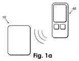
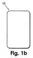
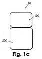
図1aは、パッチユニット(10)を含むデバイスを示す。パッチユニットは、分注装置及び監視用装置を含む。また、このデバイスは、パッチユニット(10)を制御するための遠隔制御ユニット(40)を含む。いくつかの実施形態では、パッチユニット(10)は、単一部(図1bに図示)または2部(図1cに図示)を含むように構成される可能性がある。いくつかの実施形態では、パッチユニット(10)は、再使用可能部(100)及び使い捨て部(200)を含むように構成される可能性がある。 FIG. 1a shows a device comprising a patch unit (10). The patch unit includes a dispensing device and a monitoring device. The device also includes a remote control unit (40) for controlling the patch unit (10). In some embodiments, the patch unit (10) may be configured to include a single part (shown in FIG. 1b) or two parts (shown in FIG. 1c). In some embodiments, the patch unit (10) may be configured to include a reusable part (100) and a disposable part (200).
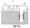
図2aは、単一部のパッチユニット(10)、ならびに皮膚付着可能なクレードルユニット(20)及び遠隔制御ユニット(40)を示す。パッチユニット(10)は、ユーザの任意でクレードルユニット(20)に接続することも、そこから分離することもできる。パッチユニット(10)をクレードルユニット(20)に接続したとき、パッチユニット(10)内に設けられたリザーバ(図2aには図示せず)と皮下挿入可能な先端(330)との間で流体連通が確立される。当業者なら理解することができるように、図2aには具体的に示されていないが、好適な電気配線接続を、先端(330)とパッチユニット(10)の間に設けることができる。パッチユニットからの流体供給は、遠隔制御ユニット(40)によってプログラムすることも、パッチユニット(10)上に設けられた少なくとも1つのボタン(15)によって手動で行うこともできる。また、遠隔制御ユニット(40)は、ユーザ入力、監視、プログラミング、及びユーザフィードバックに使用することもできる。 FIG. 2a shows a single part patch unit (10), as well as a cradle unit (20) and a remote control unit (40) capable of being attached to the skin. The patch unit (10) can be connected to or separated from the cradle unit (20) at the user's discretion. When the patch unit (10) is connected to the cradle unit (20), fluid can flow between a reservoir (not shown in FIG. 2a) provided in the patch unit (10) and a tip (330) that can be inserted subcutaneously. Communication is established. As will be appreciated by those skilled in the art, suitable electrical wiring connections can be provided between the tip (330) and the patch unit (10), although not specifically shown in FIG. 2a. Fluid supply from the patch unit can be programmed by the remote control unit (40) or manually by at least one button (15) provided on the patch unit (10). The remote control unit (40) can also be used for user input, monitoring, programming, and user feedback.
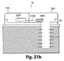
図2bは、再使用可能部(100)及び使い捨て部(200)を有する2部パッチユニットとして構成されているデバイスを示す。このデバイスは、クレードルユニット(20)及び遠隔制御ユニット(40)をさらに含む。再使用可能部(100)は、1つのハウジング内に入れられ、使い捨て部(200)は、もう1つの別個のハウジング内に入れられる。再使用可能部ハウジングと使い捨て部ハウジングは、パッチユニット(10)の動作前に互いに接続される。パッチユニット(10)をクレードルユニット(20)に接続することにより、使い捨て部(200)内に位置するリザーバ(図2bには図示せず)と先端(330)の間で流体連通がもたらされる。電気配線接続もまた、先端(330)とパッチユニット(10)の使い捨て部(200)との間で確立される(図2bには図示せず)。流体供給は、遠隔制御ユニット(40)によってプログラムする、及び/または再使用可能部ハウジング上に設けられた少なくとも1つのボタン(15)によって手動で行うこともできる。また、遠隔制御ユニット(40)は、ユーザ入力、監視、プログラミング、及びユーザフィードバックに使用することもできる。いくつかの実施形態では、データ獲得及び監視を、再使用可能部のハウジング内に位置する処理ユニットによって実施することができる。そのような監視の結果は、再使用可能部のハウジング上に位置する画面上で示すことができる。 FIG. 2b shows the device configured as a two-part patch unit with a reusable part (100) and a disposable part (200). The device further includes a cradle unit (20) and a remote control unit (40). The reusable part (100) is placed in one housing and the disposable part (200) is placed in another separate housing. The reusable part housing and the disposable part housing are connected to each other before the operation of the patch unit (10). Connecting the patch unit (10) to the cradle unit (20) provides fluid communication between a reservoir (not shown in FIG. 2b) located in the disposable part (200) and the tip (330). An electrical wiring connection is also established between the tip (330) and the disposable part (200) of the patch unit (10) (not shown in FIG. 2b). The fluid supply can also be programmed by the remote control unit (40) and / or manually by at least one button (15) provided on the reusable part housing. The remote control unit (40) can also be used for user input, monitoring, programming, and user feedback. In some embodiments, data acquisition and monitoring can be performed by a processing unit located within the housing of the reusable part. The result of such monitoring can be shown on a screen located on the housing of the reusable part.
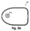
図3a及び図3bは、クレードルユニット(20)及び皮下挿入可能な先端(330)の断面図(図3a)及び上面図(図3b)を示す。クレードルユニット(20)の下向きの表面は、皮膚(5)に面する接着剤層を有する平坦なシートによって覆われている。また、クレードルユニット(20)は、パッチユニット(10)を接続及び分離するためのコネクタを備える。好適なコネクタの例は、2つのラッチとすることができよう。さらに、クレードルユニット(20)は、先端(330)用の通路として使用される開口であるウェル(310)を含む。ウェル(310)は、先端挿入後に先端(330)をクレードルユニット(20)に固定するための、上向きに延びる突起(20、21’)を含む。先端(330)は、その遠位端に開口を備え、その近位端に自己封止可能なゴム隔壁(320)を備える。隔壁(320)は、パッチユニット(10)内に設けられた接続用ルーメン(図3a及び図3bには図示せず)によって穿孔することができる。先端(330)は、挿入器を使用して自動的に、または手動で挿入することができる。 3a and 3b show a cross-sectional view (FIG. 3a) and a top view (FIG. 3b) of the cradle unit (20) and a tip (330) that can be inserted subcutaneously. The downward surface of the cradle unit (20) is covered by a flat sheet with an adhesive layer facing the skin (5). The cradle unit (20) includes a connector for connecting and separating the patch unit (10). An example of a suitable connector could be two latches. In addition, the cradle unit (20) includes a well (310) that is an opening used as a passage for the tip (330). The well (310) includes an upwardly extending protrusion (20, 21 ') for securing the tip (330) to the cradle unit (20) after tip insertion. The tip (330) has an opening at its distal end and a self-sealable rubber septum (320) at its proximal end. The partition wall (320) can be perforated by a connecting lumen (not shown in FIGS. 3a and 3b) provided in the patch unit (10). The tip (330) can be inserted automatically using an inserter or manually.
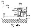
以下の考察では、「カニューレ」という用語を使用し、先端(330)をも指す。カニューレの挿入の詳細な考察は、本願の所有者が所有する/同時係属の米国特許仮出願第60/876,679号で提供されており、その開示の全体を参照により本明細書に組み込む。図4a乃至図4dは、カニューレの挿入及びクレードルユニット(20)の接着の一実施形態を示す。先端(330)の挿入は、手動(図4a乃至図4dには図示せず)で行うことも、専用のカニューレカートリッジユニット(700)が予め装填されている挿入デバイス(800)を用いて自動的に行うこともできる。図4aは、図4aの右側に示されているカニューレカートリッジユニット(700)が装填される前の挿入デバイス(挿入器)(800)を示す。カニューレカートリッジユニット(700)は、貫通用部材(702)によって取り囲まれた軟質のカニューレ(330)を含む。カニューレは、握り部分(704)、ゴム隔壁(402)、及び固定用のカニューレハブ(401)を有する。カニューレカートリッジユニット(700)は、滅菌性を維持し、不慮の穿刺を回避し、挿入器装填を容易にするプロテクタ(701)内に封入されている。カニューレカートリッジユニット(700)は、本願の所有者が所有する/同時係属の米国特許仮出願第60/937,155号で論じられており、挿入方法は、本願の所有者が所有する/同時係属の米国特許仮出願第60/937,214号で論じられており、これらの開示は、それぞれその全体を参照により本明細書に組み込む。 In the discussion below, the term “cannula” is used and also refers to the tip (330). A detailed discussion of cannula insertion is provided in US patent application Ser. No. 60 / 876,679 owned / co-pending by the owner of the present application, the entire disclosure of which is incorporated herein by reference. Figures 4a to 4d show one embodiment of cannula insertion and cradle unit (20) bonding. The tip (330) can be inserted manually (not shown in FIGS. 4a to 4d) or automatically using an insertion device (800) preloaded with a dedicated cannula cartridge unit (700). Can also be done. FIG. 4a shows the insertion device (inserter) (800) before being loaded with the cannula cartridge unit (700) shown on the right side of FIG. 4a. The cannula cartridge unit (700) includes a soft cannula (330) surrounded by a penetrating member (702). The cannula has a grip portion (704), a rubber septum (402), and a securing cannula hub (401). The cannula cartridge unit (700) is encapsulated within a protector (701) that maintains sterility, avoids accidental punctures, and facilitates inserter loading. The cannula cartridge unit (700) is discussed in US patent application 60 / 937,155 owned / co-pending by the owner of the present application, and the insertion method is owned / co-pending by the owner of the present application. US Provisional Application No. 60 / 937,214, each of which is incorporated herein by reference in its entirety.
挿入デバイス(800)は、クレードル(20)を中に装填することができるハウジング(804)を含む。ハウジングはまた、カニューレカートリッジユニット(700)を中に装填することができるスロット(806)と、挿入動作を開始するボタン(802)とを有する。 The insertion device (800) includes a housing (804) in which a cradle (20) can be loaded. The housing also has a slot (806) into which the cannula cartridge unit (700) can be loaded and a button (802) that initiates an insertion operation.
図4bは、カニューレカートリッジユニット(700)が装填された後、クレードルユニット(20)がすでに皮膚に接着されているがカニューレ(330)が挿入されていない状態の挿入デバイス(800)を示す。図4cは、ボタン(802)を押すことによってカニューレ(330)を患者の皮膚(5)内に挿入するところを概略的に示す。図4dは、握り部分(704)を握ることによって貫通用部材(702)を引き戻したところを示す。カニューレ(330)は、皮下区画内に配置されたままである。カニューレハブ(401)が、アンカ(21及び21’)によってウェル内で固定される。 FIG. 4b shows the insertion device (800) after the cannula cartridge unit (700) has been loaded, with the cradle unit (20) already adhered to the skin but the cannula (330) not inserted. FIG. 4c schematically shows the cannula (330) being inserted into the patient's skin (5) by pressing the button (802). FIG. 4d shows the penetrating member (702) pulled back by gripping the grip portion (704). The cannula (330) remains in place in the subcutaneous compartment. Cannula hub (401) is secured in the well by anchors (21 and 21 ').
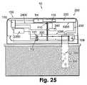
図5は、再使用可能部(100)及び使い捨て部(200)を有する2部パッチユニット(10)の断面図を示す。パッチユニット(10)は、分注装置(1005)及び監視用装置(1006)を含み、各装置は、使い捨て部または再使用可能部内に常駐する少なくとも1つの構成部品を含む。再使用可能部(100)は、電子機器(130)をさらに含み、この電子機器は、処理装置のコントローラ(図示せず)を含み、エネルギ供給源(240)を含むことができる。使い捨て部(200)は、リザーバ(220)と、供給チューブ(230)と、その供給チューブが接続される出口ポート(213)とを含む。いくつかの実施形態では、エネルギ供給源(240)を使い捨て部(200)内に設けることができる。出口ポート(213)には、パッチユニット(10)をクレードルユニット(20)に接続した後でカニューレ(330)のゴム隔壁(320)を穿孔するように適合されている接続用ルーメン(214)が設けられている。カニューレ(330)の遠位端は、皮膚(5)の下方の皮下組織内に位置することがわかる。カニューレの近位端は、ウェル(310)のところで固定される。手動操作ボタン(15)が、再使用可能部(100)のハウジング上に設けられてもよい。 FIG. 5 shows a cross-sectional view of a two-part patch unit (10) having a reusable part (100) and a disposable part (200). The patch unit (10) includes a dispensing device (1005) and a monitoring device (1006), each device including at least one component residing in a disposable or reusable part. The reusable part (100) further includes an electronic device (130), which includes a controller (not shown) of the processing device and may include an energy source (240). The disposable part (200) includes a reservoir (220), a supply tube (230), and an outlet port (213) to which the supply tube is connected. In some embodiments, an energy source (240) can be provided in the disposable part (200). The outlet port (213) has a connecting lumen (214) adapted to pierce the rubber septum (320) of the cannula (330) after connecting the patch unit (10) to the cradle unit (20). Is provided. It can be seen that the distal end of the cannula (330) is located in the subcutaneous tissue below the skin (5). The proximal end of the cannula is secured at the well (310). A manually operated button (15) may be provided on the housing of the reusable part (100).
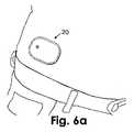
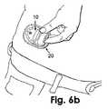
図6a乃至図6cは、クレードルユニット(20)を介してパッチユニット(10)を身体に接続するところを示す。図6aは、ユーザの皮膚に接着されたクレードルユニット(20)を示す。図6bは、パッチユニット(10)をクレードルユニット(20)に接続するところを示す。図6cは、クレードルユニット(20)に接続された後のパッチユニット(10)を示す。 Figures 6a to 6c show the patch unit (10) connected to the body via the cradle unit (20). FIG. 6a shows the cradle unit (20) glued to the user's skin. FIG. 6b shows the connection of the patch unit (10) to the cradle unit (20). FIG. 6c shows the patch unit (10) after being connected to the cradle unit (20).
図7a乃至図7cは、パッチユニット(10)を、クレードルユニット(20)を介さずに身体に直接接着するところを示す。この実施形態では、接着剤が使い捨て部(200)に付着されており、クレードルユニット(20)がない。図7aは、パッチユニット(10)の底面から接着剤(101)の紙を剥がすところを示す。図7bは、パッチユニット(10)を皮膚に接着するところを示す。図7cは、ユーザの身体に接続された後のパッチユニット(10)を示す。 Figures 7a to 7c show the patch unit (10) being glued directly to the body without the cradle unit (20). In this embodiment, the adhesive is attached to the disposable part (200) and there is no cradle unit (20). FIG. 7a shows the adhesive (101) paper being peeled from the bottom surface of the patch unit (10). FIG. 7b shows the patch unit (10) being adhered to the skin. Figure 7c shows the patch unit (10) after being connected to the user's body.
図8は、単一の先端(330)を備えるパッチユニット(10)を示す。この構成では、流体供給に使用される同じカニューレが、アナライト監視用のプローブとしても働く。パッチユニット(10)は、分注装置(1005)、監視用装置(1006)、電子機器(130)、及びエネルギ供給源(240)を含む。これらの構成部品すべてが、ユーザの皮膚(5)に直接またはクレードルユニット(20)を介して取り付けることができる単一のユニット内に配置される。限定しないが、円形、楕円形、矩形、または三角形を含む任意の断面形状で構成することができる単一の先端(330)が皮下組織内に挿入され、ユーザの身体への流体供給を実現し(したがって、カニューレとして働き)、またユーザの身体内のアナライトの監視を実現する(したがって、プローブとして働く)。遠隔制御ユニット(40)は、遠隔または直接のプログラミング及び/またはデータ処理のために使用することができる。 FIG. 8 shows a patch unit (10) with a single tip (330). In this configuration, the same cannula used for fluid supply also serves as a probe for analyte monitoring. The patch unit (10) includes a dispensing device (1005), a monitoring device (1006), an electronic device (130), and an energy source (240). All of these components are placed in a single unit that can be attached directly to the user's skin (5) or via a cradle unit (20). A single tip (330), which can be configured with any cross-sectional shape including but not limited to circular, elliptical, rectangular, or triangular, is inserted into the subcutaneous tissue to provide fluid supply to the user's body. (Hence acting as a cannula) and also provides monitoring of the analyte in the user's body (hence acting as a probe). The remote control unit (40) can be used for remote or direct programming and / or data processing.
いくつかの実施形態では、分注される流体はインスリンであり、監視されるアナライトはグルコースであり、皮下区画はISFを含む。インスリンは、分注装置(1005)によって連続的に(または3分から10分ごとなど短い間隔で)先端(330)を介して皮下区画内に分注されてもよい。グルコースレベルは、監視用装置(1006)によって連続的に、または短い間隔で周期的に、先端(330)を使用して測定することができる。 In some embodiments, the dispensed fluid is insulin, the monitored analyte is glucose, and the subcutaneous compartment includes ISF. Insulin may be dispensed into the subcutaneous compartment via the tip (330) continuously (or at short intervals, such as every 3 to 10 minutes) by the dispensing device (1005). The glucose level can be measured using the tip (330) continuously by the monitoring device (1006) or periodically at short intervals.
図9は、クレードルユニット(20)を介して身体に接続することができるパッチユニット(10)の別の実施形態を示す。図の実施形態では、クレードルユニット(20)は、1つがカニューレ(330)用、2番目がプローブ(3330)用である2つの通路を備える。パッチユニットは、分注装置(1005)、監視用装置(1006)、電子機器(130)、及びエネルギ供給源(240)を含む。いくつかの実施形態では、分注装置(1005)は、インスリンポンプの、1つまたは複数の構成部品(たとえば、リザーバ、駆動機構、及びポンプ機構)を含む。また、分注装置(1005)は、カニューレ(330)に接続させることができる出口ポートを有する。いくつかの実施形態では、監視用装置(1006)は、連続グルコースモニタの、1つまたは複数の構成部品を含むことができ、プローブ(3330)に接続させることができる。遠隔制御ユニット(40)は、分注装置(1005)及び監視用装置(1006)の遠隔プログラミング及び/またはデータ処理のために使用することができる。 FIG. 9 shows another embodiment of the patch unit (10) that can be connected to the body via the cradle unit (20). In the illustrated embodiment, the cradle unit (20) comprises two passages, one for the cannula (330) and the second for the probe (3330). The patch unit includes a dispensing device (1005), a monitoring device (1006), an electronic device (130), and an energy source (240). In some embodiments, the dispensing device (1005) includes one or more components of an insulin pump (eg, a reservoir, a drive mechanism, and a pump mechanism). The dispensing device (1005) also has an outlet port that can be connected to the cannula (330). In some embodiments, the monitoring device (1006) can include one or more components of a continuous glucose monitor and can be connected to the probe (3330). The remote control unit (40) can be used for remote programming and / or data processing of the dispensing device (1005) and the monitoring device (1006).
分注装置(1005)及び監視用装置(1006)を含む単一のパッチユニット(10)は、単一部または2部(再使用可能及び使い捨て)パッチユニット(10)とすることができる。パッチユニット(10)は、1つまたは2つのハウジング内に入れることができる。さらに、パッチユニット(10)は、遠隔制御ユニット(40)によって、及び/またはパッチハウジング上に位置する手動ボタン(図9には図示せず)によって操作することができる。いくつかの実施形態では、カニューレ(330)及びプローブ(3330)のそれぞれは、図8に示されている先端(330)と同様のものとすることができる。 The single patch unit (10) including the dispensing device (1005) and the monitoring device (1006) can be a single part or a two part (reusable and disposable) patch unit (10). The patch unit (10) can be placed in one or two housings. Furthermore, the patch unit (10) can be operated by a remote control unit (40) and / or by a manual button (not shown in FIG. 9) located on the patch housing. In some embodiments, each of the cannula (330) and probe (3330) can be similar to the tip (330) shown in FIG.
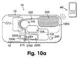
図10aは、監視用装置(1006)と、蠕動ポンプ機構(116)を使用する分注装置(1005)とを含む1部パッチユニット(10)の一実施形態を示す。流体は、蠕動ポンプ機構(116)により、リザーバ(220)から供給チューブ(230)を介して出口ポート(213)に供給される。出口ポート(213)付近に位置し、供給チューブ(230)の内部へのアクセスを有する検知手段(2000)が設けられている。検知手段(2000)は、配線(2100)によって処理装置のコントローラ(2200)に電気接続される。皮下アナライト濃度レベルが検知手段(2000)によって測定され、信号が配線(2100)を介して移送され、処理装置のコントローラ(2200)によって解析される。ポンプ機構(116)は、駆動機構(114)によって作動させることができる。いくつかの実施形態では、ポンプ機構(116)を作動させる駆動機構(114)は、限定しないが、ステッパモータ、DCモータ、またはSMAアクチュエータを含むことができる。また、エネルギ供給源(240)を設けることができ、これは1つまたは複数のバッテリとすることができる。分注装置(1005)及び監視用装置(1006)は、電子機器(130)を有するPCBによって制御されるように構成され、この電子機器が処理装置のコントローラ(2200)をも含むことができる。プログラミングは、遠隔制御ユニット(40)によって、及び/またはパッチユニット(10)上に設けられた少なくとも1つのボタン(15)によって行うことができる。 FIG. 10a shows one embodiment of a one-part patch unit (10) that includes a monitoring device (1006) and a dispensing device (1005) that uses a peristaltic pump mechanism (116). Fluid is supplied from the reservoir (220) via the supply tube (230) to the outlet port (213) by the peristaltic pump mechanism (116). Sensing means (2000) located near the outlet port (213) and having access to the interior of the supply tube (230) is provided. The detection means (2000) is electrically connected to the controller (2200) of the processing apparatus by wiring (2100). The subcutaneous analyte concentration level is measured by the sensing means (2000) and the signal is transferred via the wiring (2100) and analyzed by the controller (2200) of the processing device. The pump mechanism (116) can be actuated by a drive mechanism (114). In some embodiments, the drive mechanism (114) that operates the pump mechanism (116) can include, but is not limited to, a stepper motor, a DC motor, or an SMA actuator. An energy source (240) can also be provided, which can be one or more batteries. The dispensing device (1005) and the monitoring device (1006) are configured to be controlled by a PCB having an electronic device (130), which can also include a controller (2200) of the processing device. Programming can be performed by the remote control unit (40) and / or by at least one button (15) provided on the patch unit (10).
図10bは、監視用装置(1006)と、蠕動ポンプ機構(116)を使用する分注装置(1005)とを含む2部パッチユニット(10)の一実施形態を示す。この2部パッチユニット(10)は、再使用可能部(100)及び使い捨て部(200)を含み、各部を別々のハウジング内に入れることができる。再使用可能部(100)は、限定しないが、駆動機構(114)、ポンプ機構(116)、電子機器(130)、及び処理装置のコントローラ(2200)を含めて、監視用装置及び分注装置の比較的高価な構成部品を含む。少なくとも1つの手動操作ボタン(15)を、パッチユニット(10)を操作するために設けることができ、再使用可能部(100)上に配置することができる。使い捨て部(200)は、出口ポート(213)と、限定しないがリザーバ(220)、供給チューブ(230)、エネルギ供給源(240)を含む分注装置の比較的安価な構成部品と、限定しないが配線(2100)及びコネクタ(405)を含む監視用装置(1006)の比較的安価な構成部品とを含む。監視用装置の検知手段(2000)は、それぞれ図20a及び図20bに関連して以下で論じるように使い捨て部(200)内(外的構成)、または先端上(内的構成)に配置することができる。いくつかの実施形態では、エネルギ供給源(240)は、再使用可能部(100)内に入れることができる。アナライト監視及び流体分注は、再使用可能部(100)を使い捨て部(200)に接続して対にした後で、またこの対にされた2部をクレードルユニット(20)(図示せず)及び先端(330)に接続した後で行うことができる。流体分注の詳細な考察は、本願の所有者が所有する/同時係属の米国特許出願第11/397,115号及び国際特許出願PCT/IL06/001276に見出すことができ、それらの開示の全体を参照により本明細書に組み込む。アナライト監視の詳細な考察は、本願の所有者が所有する/同時係属の米国特許出願第11/706,606号、米国特許出願第60/876,945号、ならびに国際特許出願PCT/IL07/001096及びPCT/IL07/001177に見出すことができ、これらの開示は、それぞれその全体を参照により本明細書に組み込む。 FIG. 10b shows one embodiment of a two-part patch unit (10) that includes a monitoring device (1006) and a dispensing device (1005) that uses a peristaltic pump mechanism (116). The two-part patch unit (10) includes a reusable part (100) and a disposable part (200), each part can be placed in a separate housing. The reusable part (100) includes, but is not limited to, a monitoring device and a dispensing device, including a drive mechanism (114), a pump mechanism (116), an electronic device (130), and a processor controller (2200). Of relatively expensive components. At least one manually operated button (15) can be provided for operating the patch unit (10) and can be arranged on the reusable part (100). The disposable part (200) is not limited to the outlet port (213) and relatively inexpensive components of the dispensing device including but not limited to the reservoir (220), supply tube (230), energy supply (240). Includes relatively inexpensive components of the monitoring device (1006) including wiring (2100) and connectors (405). The sensing means (2000) of the monitoring device is located in the disposable part (200) (external configuration) or on the tip (internal configuration) as discussed below in connection with FIGS. 20a and 20b, respectively. Can do. In some embodiments, the energy source (240) can be placed in the reusable part (100). Analyte monitoring and fluid dispensing can be performed after the reusable part (100) is connected to the disposable part (200) and paired, and the paired parts are cradle unit (20) (not shown). ) And after connecting to the tip (330). A detailed discussion of fluid dispensing can be found in the co-pending US patent application Ser. No. 11 / 397,115 owned by the owner of this application and international patent application PCT / IL06 / 001276, the entire disclosure of which is hereby incorporated by reference. Is incorporated herein by reference. A detailed discussion of analyte monitoring can be found in US patent application Ser. No. 11 / 706,606, U.S. patent application Ser. No. 60 / 876,945 owned by the owner of the present application, and PCT / IL07 /. 001096 and PCT / IL07 / 001177, each of which is incorporated herein by reference in its entirety.
いくつかの実施形態では、プログラミングは、遠隔制御ユニット(40)によって、及び/またはパッチユニット(10)に設けられた少なくとも1つのボタン(15)によって行うことができる。当業者なら理解することができるように、分注装置は、様々なタイプのポンプ機構(たとえば、ペリスタポンプ、またはシリンジ内のプランジャ移動)、及び様々な駆動機構(たとえば、DCモータまたはステッパモータ、SMAから派生したモータ、ピエゾまたはベロー)を含むことができる。やはり当業者なら理解することができるように、監視用装置(1006)は、様々なタイプの監視用機構(たとえば、電気化学式、光学式、音響式なもの、またはアナライト監視のための既知の方法の任意の組合せ)を含むことができる。 In some embodiments, programming can be performed by the remote control unit (40) and / or by at least one button (15) provided on the patch unit (10). As can be appreciated by those skilled in the art, dispensing devices can include various types of pump mechanisms (eg, peristaltic pumps, or plunger movement within a syringe), and various drive mechanisms (eg, DC or stepper motors, SMAs). Motor, piezo or bellows derived from). As will also be appreciated by those skilled in the art, the monitoring device (1006) can be a variety of types of monitoring mechanisms (eg, electrochemical, optical, acoustic, or known for monitoring analytes). Any combination of methods).
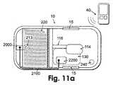
図11aは、監視用装置及び分注装置を含み、分注装置がプランジャ/ピストンポンプ機構を使用する、1部パッチユニット(10)の一実施形態を示す。流体は、プランジャ/ピストンポンプ機構(116)により、リザーバ(220)から出口ポート(213)に供給される。検知手段(2000)は、配線(2100)によって処理装置のコントローラ(2200)に電気接続される。皮下アナライト濃度レベルが検知手段(2000)によって測定され、信号が配線(2100)を介して移送され、処理装置のコントローラ(2200)によって解析される。いくつかの実施形態では、ポンプ機構(116)を作動させる駆動機構(114)は、限定しないが、ステッパモータ、DCモータ、またはSMAアクチュエータを含むことができる。また、エネルギ供給源(240)を設けることができ、これは1つまたは複数のバッテリとすることができる。分注装置及び監視用装置は、電子機器(130)を有するPCBによって制御されるように構成され、この電子機器が処理装置のコントローラ(2200)を含むことができる。プログラミングは、遠隔制御ユニット(40)によって、及び/またはパッチユニット(10)に設けられた少なくとも1つのボタン(15)によって行うことができる。 FIG. 11a shows one embodiment of a one-part patch unit (10) that includes a monitoring device and a dispensing device, where the dispensing device uses a plunger / piston pump mechanism. Fluid is supplied from the reservoir (220) to the outlet port (213) by the plunger / piston pump mechanism (116). The detection means (2000) is electrically connected to the controller (2200) of the processing apparatus by wiring (2100). The subcutaneous analyte concentration level is measured by the sensing means (2000) and the signal is transferred via the wiring (2100) and analyzed by the controller (2200) of the processing device. In some embodiments, the drive mechanism (114) that operates the pump mechanism (116) can include, but is not limited to, a stepper motor, a DC motor, or an SMA actuator. An energy source (240) can also be provided, which can be one or more batteries. The dispensing device and the monitoring device are configured to be controlled by a PCB having an electronic device (130), which can include a controller (2200) of the processing device. Programming can be performed by the remote control unit (40) and / or by at least one button (15) provided on the patch unit (10).
図11bは、監視用装置及び分注装置を含み、分注装置がプランジャ/ピストンポンプ機構(116)を使用する、2部パッチユニット(10)の例示的な実施形態を示す。この2部パッチユニット(10)は、再使用可能部(100)及び使い捨て部(200)を含み、各部を別々のハウジング内に入れることができる。再使用可能部(100)は、限定しないが、駆動機構(114)、ポンプ機構(116)、電子機器(130)、及び処理装置のコントローラ(2200)を含めることができる、監視用装置及び分注装置の比較的高価な構成部品を含む。少なくとも1つの手動操作ボタン(15)を、再使用可能部(100)上に設けることができる。使い捨て部(200)は、出口ポート(213)と、限定しないがリザーバ(220)、エネルギ供給源(240)を含めることができる分注装置の比較的安価な構成部品と、配線(2100)及び電気コネクタ(405、405’)を含めることができる監視用装置の比較的安価な構成部品とを含む。監視用装置の検知手段(2000)は、たとえばそれぞれ図20a及び図20bにおいてさらに詳述するように使い捨て部(200)内(外的構成)、または先端上(内的構成)に配置することができる。いくつかの実施形態では、エネルギ供給源(240)は、再使用可能部(100)内に入れることができる。アナライト監視及び流体分注は、再使用可能部(100)を使い捨て部(200)に接続して対にし、コネクタ(405、405’)を接続し、この対にされた2部をクレードルユニット(20)(図示せず)及び先端(330)に接続した後で行うことができる。 FIG. 11b shows an exemplary embodiment of a two-part patch unit (10) that includes a monitoring device and a dispensing device, where the dispensing device uses a plunger / piston pump mechanism (116). The two-part patch unit (10) includes a reusable part (100) and a disposable part (200), each part can be placed in a separate housing. The reusable part (100) includes, but is not limited to, a monitoring device and a distribution device that can include a drive mechanism (114), a pump mechanism (116), an electronic device (130), and a controller (2200) for a processing device. Including relatively expensive components of the device. At least one manually operated button (15) can be provided on the reusable part (100). The disposable part (200) includes an outlet port (213), a relatively inexpensive component of a dispensing device that can include, but is not limited to, a reservoir (220), an energy source (240), wiring (2100) and And relatively inexpensive components of the monitoring device that can include electrical connectors (405, 405 '). The detection means (2000) of the monitoring device can be arranged, for example, in the disposable part (200) (external configuration) or on the tip (internal configuration), as further detailed in FIGS. 20a and 20b, respectively. it can. In some embodiments, the energy source (240) can be placed in the reusable part (100). Analyte monitoring and fluid dispensing consists of reusable part (100) connected to disposable part (200) and paired, connectors (405, 405 ′) connected, and the paired two parts into cradle unit. (20) Can be done after connecting to (not shown) and tip (330).
図12乃至図14は、ピストンのプランジャポンプ機構(116)を使用する分注装置(1005)と、電気化学式検知機構を使用する監視用装置(1006)とを含む2部パッチユニット(10)の一実施形態を示す。分注装置(1005)は、再使用可能部(100)内に入れられる駆動機構(114)及びポンプ機構(116)と、使い捨て部(200)内に入れられるリザーバ(220)、供給チューブ(230)、エネルギ供給源(240)、及び出口ポート(図示せず)とを含む。電子構成部品(130)は、再使用可能部(100)内に位置し、分注装置及び監視用装置が使用することができる。電力は、使い捨て部(200)と対にされた後で電気回路を閉じる配線(2400)及びコネクタ(410)によって、使い捨て部(200)内に位置するエネルギ供給源(240)から再使用可能部(100)に供給される。いくつかの実施形態では、エネルギ供給源(240)は、再使用可能部(100)内に配置することができる。パッチユニット(10)は、先端(330)に接続可能であり、この先端を皮下組織内に挿入することができる。 12 to 14 show a two-part patch unit (10) including a dispensing device (1005) using a plunger pump mechanism (116) of a piston and a monitoring device (1006) using an electrochemical detection mechanism. One embodiment is shown. The dispensing device (1005) includes a drive mechanism (114) and a pump mechanism (116) that are placed in the reusable part (100), a reservoir (220) that is placed in the disposable part (200), and a supply tube (230). ), An energy source (240), and an outlet port (not shown). The electronic component (130) is located in the reusable part (100) and can be used by dispensing devices and monitoring devices. Electrical power is reusable from an energy source (240) located within the disposable part (200) by wires (2400) and connectors (410) that close the electrical circuit after being paired with the disposable part (200). (100). In some embodiments, the energy source (240) can be located in the reusable part (100). The patch unit (10) can be connected to a tip (330), which can be inserted into the subcutaneous tissue.
図12a及び図12bに示されているように、単一の先端(330)が、その外側表面上で長手方向に展開された電極(120、121、122)を有する。電極の一方が作用電極であり、他方が対電極であり、第3の電極が基準電極である。監視用装置(1006)は、電極(120、121、122)を有する検知手段(2000)と、配線(2100)と、コネクタ(405)と、コントローラの処理装置(2200)とを含む。少なくとも作用電極は、酵素被覆検知層によって被覆される。酵素被覆層が、グルコースを含有する周囲の流体と接触したとき、酵素触媒電気化学式反応により検知層内で電子が生じる。電子は、電極及び配線(2100)によって、コネクタ(405)を介して処理装置のコントローラ(2200)に移送され、そこで電気信号として検出され、電気信号の強度がグルコース濃度に比例する。検知手段(2000)及び先端(330)は、使い捨て部(200)内に展開することができ、処理装置のコントローラ(2200)は、再使用可能部(100)内に配置することができる。いくつかの実施形態では、図26bを参照してさらに述べるように、電子移送配線及びコネクタを、クレードルユニット(20)内に埋め込むことができる。 As shown in FIGS. 12a and 12b, a single tip (330) has electrodes (120, 121, 122) deployed longitudinally on its outer surface. One of the electrodes is a working electrode, the other is a counter electrode, and the third electrode is a reference electrode. The monitoring device (1006) includes a detecting means (2000) having electrodes (120, 121, 122), a wiring (2100), a connector (405), and a controller processing device (2200). At least the working electrode is coated with an enzyme-coated sensing layer. When the enzyme coating layer comes into contact with the surrounding fluid containing glucose, electrons are generated in the sensing layer by an enzyme-catalyzed electrochemical reaction. Electrons are transported by electrodes and wires (2100) via connector (405) to processor controller (2200) where they are detected as electrical signals where the strength of the electrical signal is proportional to the glucose concentration. The sensing means (2000) and tip (330) can be deployed in the disposable part (200) and the controller (2200) of the processing device can be placed in the reusable part (100). In some embodiments, electronic transfer wiring and connectors can be embedded in the cradle unit (20), as further described with reference to FIG. 26b.
図12a及び図12bは、電極が先端(330)の外周に配置されたときの、電気化学式検知を使用する2部パッチユニット(10)の一実施形態を示す。図12aは、皮膚(5)に付着可能であるクレードル(20)に接続されている2部パッチユニット(10)を示す。パッチユニット(10)は、再使用可能部(100)及び使い捨て部(200)を含む。監視用装置(1006)は、再使用可能部(100)内の処理装置のコントローラ(2200)及びコネクタ(405)と、使い捨て部(200)内の配線(2100)及びコネクタ(405)と、電極(120、121、及び122)を備える先端(330)とを含む。この実施形態では、電極(120、121、122)は、先端(330)の外周全体または外周の一部に沿って延びる。図12bは、長手方向の電極(120、121、122)をその外周に有する先端(330)の断面図を示す。 FIGS. 12a and 12b show one embodiment of a two-part patch unit (10) that uses electrochemical sensing when the electrodes are placed on the outer periphery of the tip (330). FIG. 12a shows a two-part patch unit (10) connected to a cradle (20) that can adhere to the skin (5). The patch unit (10) includes a reusable part (100) and a disposable part (200). The monitoring device (1006) includes a controller (2200) and a connector (405) of the processing device in the reusable part (100), a wiring (2100) and a connector (405) in the disposable part (200), and electrodes Tip (330) with (120, 121, and 122). In this embodiment, the electrodes (120, 121, 122) extend along the entire outer periphery or a portion of the outer periphery of the tip (330). FIG. 12b shows a cross-sectional view of the tip (330) having longitudinal electrodes (120, 121, 122) on its outer periphery.
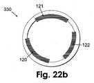
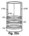
図13a乃至図13cは、電極が先端(330)の外周に横断方向で同心のリング状に位置する、電気化学式検知を使用する2部パッチユニット(10)の一実施形態を示す。図13aは、皮膚(5)に付着可能であるクレードルユニット(20)に接続されている2部パッチユニット(10)を示す。パッチユニット(10)は、再使用可能部(100)及び使い捨て部(200)を備える。監視用装置(1006)は、再使用可能部(100)内の処理装置のコントローラ(2200)及びコネクタ(405)と、使い捨て部(200)内の配線(2100)及びコネクタ(405)と、電極(120、121、122)を備える先端(330)とを含む。この実施形態では、電極(120、121、122)は、先端(330)の外周側に、同心でリング状に位置する。図13b及び図13cは、リング状の電極(120、121、122)がその外周に横断方向で位置する先端(330)、及び電流移送配線(2100)のそれぞれ縦断面図及び等角図を示す。 FIGS. 13a-c show one embodiment of a two-part patch unit (10) using electrochemical sensing, in which the electrodes are located in a concentric ring in the transverse direction around the periphery of the tip (330). FIG. 13a shows a two-part patch unit (10) connected to a cradle unit (20) that can adhere to the skin (5). The patch unit (10) comprises a reusable part (100) and a disposable part (200). The monitoring device (1006) includes a controller (2200) and a connector (405) of the processing device in the reusable part (100), a wiring (2100) and a connector (405) in the disposable part (200), and electrodes Tip (330) with (120, 121, 122). In this embodiment, the electrodes (120, 121, 122) are concentrically positioned in a ring shape on the outer peripheral side of the tip (330). FIGS. 13b and 13c show longitudinal and isometric views, respectively, of a tip (330) with a ring-shaped electrode (120, 121, 122) located in the transverse direction on its outer periphery and a current transfer wiring (2100), respectively. .
図14は、分注装置(1005)と、電気化学式監視を使用する監視用装置(1006)とを含む2部パッチユニットを示す。図14は、再使用可能部(100)及び使い捨て部(200)内の監視用装置(1006)の詳細を示す。パッチユニット(10)は、皮膚(5)に付着可能であるクレードルユニット(20)に接続されている。監視用装置(1006)は、再使用可能部(100)と使い捨て部(200)の間で分担され、電気化学式検知手段(2000)を使用する。再使用可能部(100)は、処理装置のコントローラ(2200)及び電気回路(400)を含む。回路(400)は、電極上で発生する電気化学式反応のために電位または電流を電極に与えるための、またこの電気化学式反応により電極によって生成される電流または電位を測定するための必要な構成部品を含む。配線(2100)及びコネクタ(405)は、使い捨て部(200)と再使用可能部(100)の間を電気接続するために設けられる。使い捨て部(200)は、皮下に位置する検知手段(2000)を含む先端(330)に接続される。 FIG. 14 shows a two-part patch unit that includes a dispensing device (1005) and a monitoring device (1006) that uses electrochemical monitoring. FIG. 14 shows details of the monitoring device (1006) in the reusable part (100) and the disposable part (200). The patch unit (10) is connected to a cradle unit (20) that can adhere to the skin (5). The monitoring device (1006) is shared between the reusable part (100) and the disposable part (200) and uses the electrochemical detection means (2000). The reusable part (100) includes a processor controller (2200) and an electrical circuit (400). The circuit (400) is a necessary component for applying a potential or current to the electrode for the electrochemical reaction occurring on the electrode and for measuring the current or potential generated by the electrode by this electrochemical reaction. including. Wiring (2100) and connector (405) are provided for electrical connection between disposable part (200) and reusable part (100). The disposable part (200) is connected to the tip (330) including the detection means (2000) located under the skin.
分注装置(1005)もまた再使用可能部(100)及び使い捨て部(200)内に入れることができ、再使用可能部(100)は、駆動機構(114)及びポンプ機構(116)を含み、使い捨て部(200)は、リザーバ(220)及び供給チューブ(230)を含む。パッチユニット(10)を先端(330)に接続したとき、リザーバから先端(330)を介して体内に流体を供給することができ、体内のアナライトを監視することができる。 A dispensing device (1005) can also be placed in the reusable part (100) and the disposable part (200), the reusable part (100) including a drive mechanism (114) and a pump mechanism (116). The disposable part (200) includes a reservoir (220) and a supply tube (230). When the patch unit (10) is connected to the tip (330), fluid can be supplied from the reservoir to the body via the tip (330), and the analyte in the body can be monitored.
図15乃至図17は、ポンプ機構(116)を使用する分注装置(1005)と、光学式検知機構を使用する監視用装置(1006)とを含む2部パッチユニット(10)の実施形態を示す。分注装置(1005)は駆動機構(114)及びポンプ機構(116)を含み、これらは再使用可能部(100)内に含まれる。さらに、分注装置(1005)は、使い捨て部(200)内に含まれるリザーバ(220)、供給チューブ(230)、エネルギ供給源(240)、及び出口ポート(図示せず)を含む。電子機器(130)及び処理装置のコントローラ(2200)は、再使用可能部(100)内に位置し、分注装置(1005)及び監視用装置(1006)が共に使用することができる。いくつかの実施形態では、エネルギ供給源(240)は、再使用可能部(100)内に配置することができる。 FIGS. 15-17 illustrate an embodiment of a two-part patch unit (10) that includes a dispensing device (1005) that uses a pump mechanism (116) and a monitoring device (1006) that uses an optical sensing mechanism. Show. The dispensing device (1005) includes a drive mechanism (114) and a pump mechanism (116), which are included in the reusable part (100). Furthermore, the dispensing device (1005) includes a reservoir (220), a supply tube (230), an energy source (240), and an outlet port (not shown) contained within the disposable part (200). The electronic device (130) and the processing device controller (2200) are located in the reusable part (100) and can be used by both the dispensing device (1005) and the monitoring device (1006). In some embodiments, the energy source (240) can be located in the reusable part (100).
図の実施形態における監視用装置(1006)は、少なくとも1つの発光源(101)と、少なくとも1つの検出器(102)と、少なくとも1つの光偏向手段(109)とを含む。発光源(101)から体内に伝播する光の経路が実線で示されており、身体から検出器(102)に伝播する光の経路が破線で示されている。発光源(101)からの発光された光は、偏向手段(109)によって身体に向かって偏向され、返された光は、検出器(102)に到達し、処理装置のコントローラ(2200)によって解析される。発光源(101)、検出器(102)、及び処理装置のコントローラ(2200)は、再使用可能部(100)内に配置することができ、偏向手段(109)は、再使用可能部(100)内に配置することができる。再使用可能部(100)及び使い捨て部(200)内に窓(111、112)が設けられる。窓(111、112)は、再使用可能部(100)と使い捨て部(200)が対にされた後で位置合わせされ、上記経路に沿った光の通過を維持する。 The monitoring device (1006) in the illustrated embodiment includes at least one light source (101), at least one detector (102), and at least one light deflection means (109). The path of light propagating from the light source (101) into the body is indicated by a solid line, and the path of light propagating from the body to the detector (102) is indicated by a broken line. The emitted light from the light source (101) is deflected towards the body by the deflecting means (109), and the returned light reaches the detector (102) and is analyzed by the controller (2200) of the processing device. Is done. The light source (101), the detector (102), and the controller (2200) of the processing device can be placed in the reusable part (100), and the deflection means (109) is placed in the reusable part (100). ). Windows (111, 112) are provided in the reusable part (100) and the disposable part (200). The windows (111, 112) are aligned after the reusable part (100) and the disposable part (200) are paired to maintain the passage of light along the path.
図15は、皮膚(5)に付着可能であるクレードルユニット(20)に接続された2部パッチユニット(10)、及び再使用可能部(100)と使い捨て部(200)の間で分割される光学ベースの監視用装置(1006)の構成部品を示す。光源(101)から発せられた光は、偏向手段(109)によって先端(330)に向かって偏向され、皮下組織のISF内に入る。発光された光のスペクトルは、測定されるアナライト(13)に応じて変わる可能性がある。たとえば、アナライトがグルコースである場合、近赤外(NIR)、中赤外、または可視光範囲内のスペクトルを(合わせて、または別々に)使用することができる。先端(330)の遠位端に向かって伝播する光(300)は、先端(330)に、次いで偏向手段(109)を介して検出器(102)に戻る。反射光スペクトルを処理装置のコントローラ(2200)によって解析し、アナライト濃度レベルを得る。光を発光源(101)から先端(330)を介して身体に向けて送り、次いで検出器(102)に戻すための様々な構成を有するパッチユニット(10)の実施形態が、米国特許仮出願第61/004,039号で論じられており、その開示の全体を参照により本明細書に組み込む。 FIG. 15 is split between a two-part patch unit (10) connected to a cradle unit (20) that can adhere to the skin (5), and a reusable part (100) and a disposable part (200) The components of the optical based monitoring device (1006) are shown. The light emitted from the light source (101) is deflected toward the tip (330) by the deflecting means (109) and enters the ISF of the subcutaneous tissue. The spectrum of the emitted light can vary depending on the analyte (13) being measured. For example, if the analyte is glucose, a spectrum in the near infrared (NIR), mid-infrared, or visible light range can be used (together or separately). Light (300) propagating towards the distal end of tip (330) returns to tip (330) and then to detector (102) via deflection means (109). The reflected light spectrum is analyzed by the processor controller (2200) to obtain the analyte concentration level. Embodiments of the patch unit (10) having various configurations for sending light from the light emitting source (101) through the tip (330) toward the body and then back to the detector (102) are disclosed in US Patent Provisional Application 61 / 004,039, the entire disclosure of which is incorporated herein by reference.
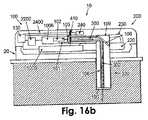
図16a乃至図17cは、分注装置(1005)及び監視用装置(1006)を有する2部パッチユニット(10)の実施形態を示す。分注装置(1005)は、再使用可能部(100)内の駆動機構及びポンプ機構(図16a乃至図17cには図示せず)と、使い捨て部(200)内のリザーバ(220)及び供給チューブ(230)とを含む。分注装置(1005)は、リザーバ(220)から供給チューブ(230)を介し、ポンプ機構(図16a乃至図17cには図示せず)を介し、先端(330)を介して身体に流体を供給する。監視用装置(1006)は、再使用可能部(100)内に位置する発光源(101)及び検出器(102)と、再使用可能部(100)内にも使い捨て部(200)内にも配置することができる光ファイバ(106)及びレンズ(105)とを含む。偏向手段(109)は、身体への、また身体からの光(300)を配向する反射ミラー(108)を含むことができる。いくつかの実施形態では、再使用可能部(100)と使い捨て部(200)の間、及び/または先端(330)の遠位端に、追加の光結合器(190)が存在してもよい。光結合器(190)は、限定しないが、反射光が組織から光ファイバ(106)に再結合しないようにするために、ある角度(たとえば、8度)で傾斜した窓を含むことができる。 Figures 16a to 17c show an embodiment of a two-part patch unit (10) having a dispensing device (1005) and a monitoring device (1006). The dispensing device (1005) includes a drive mechanism and pump mechanism (not shown in FIGS. 16a to 17c) in the reusable part (100), a reservoir (220) and a supply tube in the disposable part (200). (230). The dispensing device (1005) supplies fluid to the body from the reservoir (220) through the supply tube (230), through the pump mechanism (not shown in FIGS. 16a to 17c), and through the tip (330). To do. The monitoring device (1006) includes a light source (101) and a detector (102) located in the reusable part (100), and in both the reusable part (100) and the disposable part (200). An optical fiber (106) and a lens (105) that can be arranged. The deflection means (109) may include a reflective mirror (108) that directs light (300) to and from the body. In some embodiments, an additional optical coupler (190) may be present between the reusable part (100) and the disposable part (200) and / or at the distal end of the tip (330). . The optical coupler (190) can include, but is not limited to, a window that is inclined at an angle (eg, 8 degrees) to prevent the reflected light from recombining from tissue to the optical fiber (106).
図16a乃至図16cは、分注装置(1005)及び監視用装置(1006)を備える2部パッチユニットの一実施形態を示す。監視用装置(1006)は、再使用可能部(100)と使い捨て部(200)の間を通る光(300)を集束するためのレンズ(105)を含む。いくつかの実施形態では、光学レンズ(105)は、発光された光及び戻る光の散乱を狭めるためのコリメート手段または集束手段として働く。レンズは、限定しないが、プラスチック、ガラス、石英を含む、様々な好適な材料製とすることができる。プラスチックレンズの使用が最もコスト効果的なものとなり得るが、ガラス及び石英は、優れた光学特性を有する。 Figures 16a to 16c show one embodiment of a two-part patch unit comprising a dispensing device (1005) and a monitoring device (1006). The monitoring device (1006) includes a lens (105) for focusing light (300) passing between the reusable part (100) and the disposable part (200). In some embodiments, the optical lens (105) acts as a collimating or focusing means to narrow the scattering of emitted light and returning light. The lens can be made of a variety of suitable materials including, but not limited to, plastic, glass, quartz. Although the use of plastic lenses can be the most cost effective, glass and quartz have excellent optical properties.
図16a及び図16bは、レンズ(105)が再使用可能部(100)と使い捨て部(200)の間に位置するパッチユニット(10)のそれぞれ側面図及び上面図を示す。図16cは、再使用可能部(100)と使い捨て部(200)の間の接触表面、及びレンズ(105)を介した2部間の光(300)の通過の拡大図を示す。 16a and 16b show a side view and a top view, respectively, of the patch unit (10) in which the lens (105) is located between the reusable part (100) and the disposable part (200). FIG. 16c shows an enlarged view of the contact surface between the reusable part (100) and the disposable part (200) and the passage of light (300) between the two parts via the lens (105).
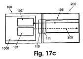
図17a乃至図17cは、分注装置(1005)及び監視用装置(1006)を有する2部パッチユニット(10)の側面図(図17a)及び上面図(図17b)を示す。監視用装置(1006)を通る光路は、それぞれ再使用可能部(100)及び使い捨て部(200)内に位置し、これらの2部間での光(300)の通過を可能にする、2つの位置合わせされた光学窓(110、111)を含む。光学窓(110、111)は、再使用可能部(100)と使い捨て部(200)の間で光(300)の通過を可能にするための手段として働く。図17cは、再使用可能部(100)と使い捨て部(200)の間を通り、光ファイバ(106)及び2つの光学窓(110、111)を通過する光の方向(300)を示す。いくつかの実施形態では、2つの窓(110、111)は、光ファイバ(106)内への逆方向の光反射を防止するために、両方とも、または別々に、たとえば約8度だけ傾斜させることができる。他の実施形態では、2つの光学窓(110、111)は、アナライト濃度レベルを検出するのに関連する波長にある光に対して半透明であり、光が窓(110、111)を通過することができる材料製である。窓(110、111)は、限定しないが、プラスチック、ガラス、または石英を含む、様々な好適な材料から作ることができる。いくつかの実施形態では、光学窓(110、111)は、発光された光または返された光が光学窓を通過したとき、起こり得るどんな光の散乱をも狭めるように、集束手段として働く。 17a to 17c show a side view (FIG. 17a) and a top view (FIG. 17b) of a two-part patch unit (10) having a dispensing device (1005) and a monitoring device (1006). The light paths through the monitoring device (1006) are located in the reusable part (100) and the disposable part (200), respectively, and allow the passage of light (300) between these two parts. Aligned optical windows (110, 111) are included. The optical windows (110, 111) serve as a means for allowing light (300) to pass between the reusable part (100) and the disposable part (200). FIG. 17c shows the direction of light (300) passing between the reusable part (100) and the disposable part (200) and passing through the optical fiber (106) and the two optical windows (110, 111). In some embodiments, the two windows (110, 111) are tilted both or separately, eg, by about 8 degrees, to prevent reverse light reflection into the optical fiber (106). be able to. In other embodiments, the two optical windows (110, 111) are translucent to light at a wavelength associated with detecting the analyte concentration level, and the light passes through the windows (110, 111). Made of material that can. The windows (110, 111) can be made from a variety of suitable materials including, but not limited to, plastic, glass, or quartz. In some embodiments, the optical window (110, 111) serves as a focusing means to narrow any possible light scattering when emitted or returned light passes through the optical window.
監視用装置(1006)は、以下の光学手段のいずれか1つを使用することができる。 The monitoring device (1006) can use any one of the following optical means.
○ 近赤外(NIR)分光法:グルコースのNIR透過率及び反射率測定は、グルコース特有の特性がNIRスペクトル内に埋め込まれており、多変量解析法を使用することによって抽出することができることに基づくものである(Diab Tech Ther 2004;6(5):660−697,Anal.Chem.2005,77:4587−4594)。 ○ Near-infrared (NIR) spectroscopy: NIR transmittance and reflectance measurements of glucose can be extracted by using the multivariate analysis method because the unique characteristics of glucose are embedded in the NIR spectrum. (Diab Tech The 2004; 6 (5): 660-697, Anal. Chem. 2005, 77: 4587-4594).
○ 中赤外分光法:この範囲は、グルコース、タンパク質、及び水など、生物学的に重要な分子の非常に独特かつ特徴的な基本振動によって生成される吸光度のフィンガープリントを含む。9.25μm及び9.65μmに、グルコースの2つの強い帯域が見られる。 O Mid-infrared spectroscopy: This range includes absorbance fingerprints generated by the very unique and characteristic fundamental vibrations of biologically important molecules such as glucose, proteins, and water. Two strong bands of glucose are seen at 9.25 μm and 9.65 μm.
○ 光の散乱:光の散乱は、局所反射率(空間的に分解された拡散反射率)またはNIR周波数領域反射率技法によって測定される。局所反射率では、細い光ビームが身体部の表面上の限られた領域を照明し、反射された信号が、照明点から離れた数箇所で測定される。局所反射率測定も周波数領域測定もグルコース濃度の変化に基づくものであり、グルコース濃度は、ISFと組織繊維の間の屈折率不一致に影響を及ぼす。 O Light scattering: Light scattering is measured by local reflectivity (spatially resolved diffuse reflectivity) or NIR frequency domain reflectivity techniques. With local reflectivity, a thin light beam illuminates a limited area on the surface of the body part, and the reflected signal is measured at several points away from the illumination point. Both local reflectance measurements and frequency domain measurements are based on changes in glucose concentration, which affects the refractive index mismatch between ISF and tissue fibers.
○ ラマン分光法:ラマン効果は、エネルギが光と物質の間で交換される基本的な過程である。ラマン分光法では、しばしば「励起」光とも呼ばれる入射光が分子を励起し、振動運動させる。光エネルギが周波数に比例するため、この散乱光の周波数変化は、散乱する分子の振動周波数と等しくなければならない。散乱する分子と入射光の間のエネルギ交換のこの過程が、ラマン効果として知られている。ラマン散乱光は、分光計によって制御し、「スペクトル」として表示することができ、その強度がその周波数変化の関数として表示される。各分子種は、それ自体独特の分子振動の集合を有するため、特定の種のラマンスペクトルは、それぞれがその分子の特徴的な振動周波数のうちの1つによってシフトされた一連のピークまたは「帯域」からなることになる。したがって、ラマン分光法を使用し、グルコースの組織及び血中濃度を正確に測定することができる(Phys.Med.Biol.2000 45(2)R1−R59)。 ○ Raman spectroscopy: The Raman effect is a fundamental process in which energy is exchanged between light and matter. In Raman spectroscopy, incident light, often referred to as “excitation” light, excites molecules and causes them to oscillate. Since the light energy is proportional to the frequency, the frequency change of the scattered light must be equal to the vibration frequency of the scattering molecule. This process of energy exchange between scattering molecules and incident light is known as the Raman effect. The Raman scattered light can be controlled by a spectrometer and displayed as a “spectrum”, whose intensity is displayed as a function of its frequency change. Since each molecular species has its own set of molecular vibrations, the Raman spectrum of a particular species is a series of peaks or “bands” each shifted by one of its characteristic vibrational frequencies. ". Thus, Raman spectroscopy can be used to accurately measure glucose tissue and blood concentrations (Phys. Med. Biol. 2000 45 (2) R1-R59).
○ 蛍光エネルギ移動(Fluorescence energy transfer/FRET)をベースとする検定:コンカナバリンAがドナーとしてNIR蛍光性の高いタンパク質のアロフィコシアニンで標識され、デキストランがアクセプタとしてマラカイトグリーンで標識される(J Photochem Photobiol 2000;54:26−34;Anal Biochem 2001;292:216−221)。レクチンに対する結合からのデキストランの競争的置換(competitive displacement)が、グルコース濃度が上昇しつつあるとき発生し、強度または寿命(時間相関された単一光子計数)として測定されるFRETの減少をもたらす。 O Fluorescence energy transfer / FRET-based assay: Concanavalin A is labeled with donor NAL-fluorescent protein allophycocyanin and dextran is labeled with malachite green as an acceptor (J Photochem Photobiol 2000) 54: 26-34; Anal Biochem 2001; 292: 216-221). Competitive displacement of dextran from binding to lectin occurs when glucose concentration is increasing, resulting in a decrease in FRET measured as intensity or lifetime (time correlated single photon count).
○ 光音響法:光音響(PA)は、光の吸収によって生み出される超音波を使用する。媒質が、その媒質内の特定の分子種によって吸収される波長のレーザパルスによって励起される。光の吸収、及び後続の放射のない崩壊が、媒質内で非常に小さい局所加熱を引き起こし、それにより、ハイドロホンまたは圧電デバイスによって検出可能な超音波の圧力波が生成される。これらの音響信号を解析することにより、媒質内での光の吸収の深さプロファイルをマッピングすることができる。血中グルコース濃度の監視用の非侵襲的な道具として働くことができる光音響技法によって、グルコーストレンドを追跡することができる(Clin Chem1999 45(9):1587−95)。 ○ Photoacoustic method: Photoacoustic (PA) uses ultrasound generated by light absorption. The medium is excited by a laser pulse of a wavelength that is absorbed by a particular molecular species within the medium. Absorption of light and subsequent decay without radiation causes very little local heating in the medium, thereby producing an ultrasonic pressure wave that can be detected by a hydrophone or piezoelectric device. By analyzing these acoustic signals, the depth profile of light absorption in the medium can be mapped. Glucose trends can be tracked by photoacoustic techniques that can serve as a non-invasive tool for monitoring blood glucose levels (Clin Chem 1999 45 (9): 1587-95).
図18及び図19は、再使用可能部(100)及び使い捨て部(200)を有する2部パッチユニット(10)の実施形態を示す。パッチユニット(10)は、皮膚(5)に付着可能であるクレードルユニット(20)に接続されている。パッチユニット(10)は、先端(330)を使用する分注装置及び監視用装置(図18及び図19には図示せず)を含む。図の実施形態では、先端(330)が半透性または浸透性であり、アナライト分子がその膜壁を介して先端(330)内に拡散することを可能にする。分注される流体(たとえば、インスリン)が先端(330)内の溶液として使用され、その溶液内に、周囲のISFからの分子が拡散される可能性がある。半透膜または透析膜を介したアナライト分子の拡散は、濃度勾配の指示に従う。先端(330)内のアナライト濃度は、濃度平衡を達成するための時間として規定される回復時間に応じて、周囲のISF内のアナライト濃度に比例するか、またはそれに等しい。 18 and 19 show an embodiment of a two-part patch unit (10) having a reusable part (100) and a disposable part (200). The patch unit (10) is connected to a cradle unit (20) that can adhere to the skin (5). The patch unit (10) includes a dispensing device that uses the tip (330) and a monitoring device (not shown in FIGS. 18 and 19). In the illustrated embodiment, the tip (330) is semi-permeable or permeable, allowing analyte molecules to diffuse into the tip (330) through its membrane wall. A fluid to be dispensed (eg, insulin) is used as a solution in the tip (330) into which molecules from the surrounding ISF can diffuse. Diffusion of analyte molecules through a semi-permeable membrane or dialysis membrane follows a concentration gradient indication. The analyte concentration in the tip (330) is proportional to or equal to the analyte concentration in the surrounding ISF, depending on the recovery time defined as the time to achieve concentration equilibrium.
図18は、単一の皮下挿入可能な先端(330)に接続されているパッチユニット(10)の一実施形態を示す。先端(330)は、低分子量の分子(13)(たとえば、グルコース)の拡散を可能にし、一方、高分子量の分子(14)に対する障壁をもたらす。 FIG. 18 shows one embodiment of the patch unit (10) connected to a single subcutaneously insertable tip (330). The tip (330) allows diffusion of low molecular weight molecules (13) (eg, glucose), while providing a barrier to high molecular weight molecules (14).
図19は、先端(330)が、小さい分子量の分子(13)に対しても大きい分子量の分子(14)に対しても浸透性である透析膜を含む一実施形態を示す。浸透性の先端は、より安価であり、急速な回復時間を可能にするが、(通常、小さい分子量の分子からなる)特定のアナライトの監視をあまり正確でないものにし得る。 FIG. 19 shows an embodiment in which the tip (330) includes a dialysis membrane that is permeable to both low molecular weight molecules (13) and large molecular weight molecules (14). The osmotic tip is cheaper and allows rapid recovery times, but can make monitoring of specific analytes (usually consisting of small molecular weight molecules) less accurate.
いくつかの実施形態では、アナライト濃度レベルを監視するために、また流体を供給するために使用される先端(330)が、当技術分野で知られているように、微小透析(MD)プローブまたは微小かん流(MP)プローブである。プローブは、分注される流体(たとえば、インスリン)を、または追加の/代替のかん流流体(たとえば、生理食塩水)をかん流させることができる。先端の膜は、半透性でも浸透性でもよい。MDプローブは当技術分野で知られており、それらの説明の例は、Ungerstedtの米国特許第4,694,832号、ならびに「CMA 60 Microdialysis Catheter」または「CMA 70 Brain Microdialysis Catheters」という名称のCMA/Microdialysis AB Companyの文書から見出すことができる。挿入用のカニューレと結合されたMDプローブもまた、Modelらの米国特許出願第2005/0119588号で論じられている。 In some embodiments, the tip (330) used to monitor the analyte concentration level and to supply fluid is a microdialysis (MD) probe as is known in the art. Or a microperfusion (MP) probe. The probe can perfuse fluid to be dispensed (eg, insulin) or additional / alternative perfusion fluid (eg, saline). The tip membrane may be semi-permeable or permeable. MD probes are known in the art and examples of their description include Ungerstedt US Pat. No. 4,694,832 and a CMA named “CMA 60 Microdialysis Catheters” or “CMA 70 Brain Microdialysis Catheters”. / Microdialysis AB Company document. An MD probe coupled to an insertion cannula is also discussed in Model et al. US Patent Application No. 2005/0119588.
図20a及び図20bは、MD先端(図20a)またはMP先端(図20b)が使用される先端(330)の実施形態を示し、先端(330)は、底部(331)またはその側部(332)に開口を含み、先端(33)に入る流体が先端(330)を介してパッチユニット(10)からユーザの身体に供給されることを可能にすることを除いて、当業者に知られているMDプローブまたはMPプローブと同様である。したがって、この実施形態の先端(330)は、流体を体内に分注するための手段としても、アナライト濃度を監視するためのMDプローブまたはMPプローブとしても働く。 FIGS. 20a and 20b show an embodiment of the tip (330) where an MD tip (FIG. 20a) or MP tip (FIG. 20b) is used, the tip (330) being the bottom (331) or its side (332). ) To the user's body from the patch unit (10) via the tip (330), allowing the fluid entering the tip (33) to be supplied to the user's body. It is the same as the MD probe or MP probe. Thus, the tip (330) of this embodiment serves both as a means for dispensing fluid into the body and as an MD or MP probe for monitoring analyte concentration.
分子拡散に基づくものであり、先端(330)が半透性または浸透性である実施形態では、アナライト検知手段を、以下の構成のうちの1つで構成することができる。 In embodiments that are based on molecular diffusion and the tip (330) is semi-permeable or permeable, the analyte detection means can be configured in one of the following configurations.
1.内的構成 − 検知手段が先端のところにあり、皮下区画内に位置する。 1. Internal configuration-the detection means is at the tip and is located in the subcutaneous compartment.
2.外的構成 − 検知手段が、皮下区画の外側に位置するパッチユニット内にある。アナライトに富んだ流体をパッチユニットに移送することができ、そこでアナライト濃度検知を身体の外側で実施することができる。この構成では、分注装置は、アナライトに富んだ流体を、皮下に位置する先端の遠位端からパッチ内に位置する先端の近位端に(たとえば、流体供給の方向を逆転することによって)移送するための手段を含む。 2. External configuration-the sensing means is in a patch unit located outside the subcutaneous compartment. Analyte-rich fluid can be transferred to the patch unit, where analyte concentration detection can be performed outside the body. In this configuration, the dispensing device moves the analyte-rich fluid from the distal tip of the tip located subcutaneously to the proximal end of the tip located within the patch (eg, by reversing the direction of fluid supply). ) Including means for transport.
アナライト検知手段は、電気化学式、光学式、音響式なもの、または当業者に知られている任意の他のアナライト検知手段に基づくものとすることができる。 The analyte detection means may be electrochemical, optical, acoustic, or based on any other analyte detection means known to those skilled in the art.
図21a及び図21bは、再使用可能部(100)及び使い捨て部(200)を有する2部パッチユニット(10)を示す。パッチユニット(10)は、分注装置及び電気化学式監視用装置を含み、クレードルユニット(20)に接続されている。パッチユニット(10)は、半透性または浸透性である膜を有する先端(330)に接続することができる。監視用装置は、検知手段(2000)を備える。図21a及び図21bは、先端内(すなわち、内的)(図21a)、及びパッチ内(すなわち、外的)(図21b)の、検知手段(2000)の2つの構成を示す。 Figures 21a and 21b show a two-part patch unit (10) having a reusable part (100) and a disposable part (200). The patch unit (10) includes a dispensing device and an electrochemical monitoring device, and is connected to the cradle unit (20). The patch unit (10) can be connected to a tip (330) having a membrane that is semi-permeable or permeable. The monitoring device includes detection means (2000). Figures 21a and 21b show two configurations of the sensing means (2000) within the tip (ie internal) (Figure 21a) and within the patch (ie external) (Figure 21b).
図21aは、内的検知手段(2000)を使用する、分注装置及び監視用装置(図21a及び図21bには図示せず)を含む2部パッチユニット(10)の一実施形態を示す。パッチユニット(10)は、皮膚(5)に付着可能であるクレードル(20)に接続されている監視用装置は、再使用可能部(100)内に位置する処理装置のコントローラ(2200)と、再使用可能部及び使い捨て部(100及び200)内に位置する配線(2100)と、検知手段(2000)を有する先端(330)とを含む。検知手段(2000)は、先端(330)内に位置する(内的構成)。先端(330)は、アナライトが濃度勾配の方向(矢印によって図示)で拡散することを可能にする透析膜または半透膜を有する。 FIG. 21a shows one embodiment of a two-part patch unit (10) that includes a dispensing device and a monitoring device (not shown in FIGS. 21a and 21b) using an internal sensing means (2000). The patch unit (10) is connected to the cradle (20) attachable to the skin (5), the monitoring device is a controller (2200) of the processing device located in the reusable part (100), It includes a wiring (2100) located within the reusable and disposable parts (100 and 200) and a tip (330) having sensing means (2000). The detection means (2000) is located in the tip (330) (internal configuration). The tip (330) has a dialysis or semi-permeable membrane that allows the analyte to diffuse in the direction of the concentration gradient (illustrated by arrows).
図21bは、外的検知手段を使用する、分注装置及び監視用装置(図21bには図示せず)を含む2部パッチユニット(10)の一実施形態を示す。パッチユニット(10)は、皮膚(5)に付着可能であるクレードルユニット(20)に接続されている。監視用装置は、再使用可能部(100)内に位置する処理装置のコントローラ(2200)と、使い捨て部(200)内に位置する配線(2100)と、先端(330)とを含む。検知手段(2000)は、パッチ(10)内、好ましくは使い捨て部(200)内に位置する(外的構成)。先端(330)は、アナライト分子が濃度勾配の方向(矢印によって図示)で拡散することを可能にする透析膜または半透膜を有する。分注装置は、アナライトに富んだ流体を先端(330)からパッチユニット(10)内に移送するための手段(図示せず)を含む。そのような移送の1つの方法は、米国特許仮出願第60/928,054号に対する優先権を共に主張し、それらの開示の全体を参照により本明細書に組み込む、本願の所有者が所有する/同時係属の国際特許出願PCT/US08/062928及び米国特許出願第12/116,546号に開示されているように、流体供給の方向を逆転することを含む。 FIG. 21b shows one embodiment of a two-part patch unit (10) including a dispensing device and a monitoring device (not shown in FIG. 21b) using external sensing means. The patch unit (10) is connected to a cradle unit (20) that can adhere to the skin (5). The monitoring device includes a controller (2200) of the processing device located in the reusable part (100), wiring (2100) located in the disposable part (200), and a tip (330). The detection means (2000) is located in the patch (10), preferably in the disposable part (200) (external configuration). The tip (330) has a dialysis or semi-permeable membrane that allows analyte molecules to diffuse in the direction of the concentration gradient (illustrated by arrows). The dispensing device includes means (not shown) for transferring the analyte rich fluid from the tip (330) into the patch unit (10). One method of such transfer is owned by the owner of the present application, both claiming priority to US Provisional Application No. 60 / 928,054, the entire disclosure of which is incorporated herein by reference. / Reversing the direction of fluid supply as disclosed in co-pending international patent application PCT / US08 / 062928 and US patent application Ser. No. 12 / 116,546.
図22a乃至図22cは、分注装置(1005)及び電気化学式監視用装置(1006)を含む2部パッチユニット(10)の一実施形態を示す。パッチユニット(10)は、再使用可能部(100)及び使い捨て部(200)を含み、皮膚(5)に付着可能であるクレードルユニット(20)に接続されている。分注装置(1005)は、再使用可能部(100)内に位置する処理装置のコントローラ(2200)、駆動機構(114)、及びポンプ機構(116)と、使い捨て部(200)内に位置するリザーバ(220)及び供給チューブ(230)とを含む。監視用装置(1006)は、再使用可能部(100)内に位置する処理装置のコントローラ(2200)と、配線(2100)と、コネクタ(405)と、内的とすることも外的とすることもできる電気化学式検知手段とを含む。 22a-c show one embodiment of a two-part patch unit (10) that includes a dispensing device (1005) and an electrochemical monitoring device (1006). The patch unit (10) includes a reusable part (100) and a disposable part (200) and is connected to a cradle unit (20) that can adhere to the skin (5). The dispensing device (1005) is located within the controller (2200), drive mechanism (114), and pump mechanism (116) of the processing device located within the reusable part (100) and the disposable part (200). A reservoir (220) and a supply tube (230). The monitoring device (1006) is internal to the controller (2200), the wiring (2100), the connector (405) of the processing device located in the reusable part (100), and external. And electrochemical detection means.
図22aは、検知手段の内的構成を含む電気化学ベースの監視用装置の例示的な実施形態を示す。検知手段は、先端(330)上で皮下区画内に位置しており、作用電極(120)、対電極(121)、及び基準電極(122)を含む。これらの電極は、先端の外側または内側に長手方向で配置することができる。電流が電極から配線(2100)及びコネクタ(405)によって処理装置のコントローラ(2200)に移送される。 FIG. 22a shows an exemplary embodiment of an electrochemical-based monitoring device including the internal configuration of the sensing means. The sensing means is located in the subcutaneous compartment on the tip (330) and includes a working electrode (120), a counter electrode (121), and a reference electrode (122). These electrodes can be arranged longitudinally outside or inside the tip. Current is transferred from the electrodes to the controller (2200) of the processing equipment by wiring (2100) and connector (405).
図22b及び図22cは、先端(330)の内側に横断方向で位置する同心の、リング状の電極(120、121、122)の、それぞれ横断面図(図22b)及び等角図(図22c)を示す。図の実施形態では、先端(330)は、浸透性または半透性である。いくつかの実施形態では、これらの電極は、先端(330)の外側に配置することができる。先端(330)は、円形、楕円形、矩形とすることも、平坦な外形、または任意の他の形状を有することもできる。先端(330)は、非浸透性でも半透性でもよく、これらの電極は、先端(330)の外側表面または内側表面に配置することができる。 Figures 22b and 22c show a cross-sectional view (Figure 22b) and an isometric view (Figure 22c), respectively, of concentric, ring-shaped electrodes (120, 121, 122) located transversely inside the tip (330). ). In the illustrated embodiment, the tip (330) is permeable or semi-permeable. In some embodiments, these electrodes can be placed outside the tip (330). The tip (330) can be circular, oval, rectangular, have a flat profile, or any other shape. The tip (330) may be impermeable or semi-permeable, and these electrodes may be placed on the outer or inner surface of the tip (330).
図23は、外的検知手段を含む電気化学ベースの監視用装置(1006)の一実施形態を示す。検知手段(2000)は、先端(330)上でパッチユニット(10)内に位置しており、少なくとも1つの作用電極(120)、対電極(121)、または基準電極(122)を含むことができる。これらの電極は、先端(330)の外側表面または内側表面に配置することができる。電流が電極から配線(2100)及びコネクタ(405)によって処理装置のコントローラ(2200)に移送される。皮下の先端部分(先端の遠位端)からのアナライトに富んだ溶液が、(先端内の濃度勾配に従った)先端に沿った拡散によって、または(たとえば、ポンプ機構の方向を逆転させることによって生み出される先端内の流体の逆流による)強制流体移送によって、検知手段(先端の近位端)に到達することができる。 FIG. 23 shows one embodiment of an electrochemical-based monitoring device (1006) that includes external sensing means. The sensing means (2000) is located in the patch unit (10) on the tip (330) and includes at least one working electrode (120), counter electrode (121), or reference electrode (122). it can. These electrodes can be placed on the outer or inner surface of the tip (330). Current is transferred from the electrodes to the controller (2200) of the processing equipment by wiring (2100) and connector (405). Analyte-rich solution from the subcutaneous tip (the distal end of the tip) diffuses along the tip (according to the concentration gradient within the tip) or (eg, reverses the direction of the pump mechanism) The sensing means (proximal end of the tip) can be reached by forced fluid transfer (by backflow of fluid in the tip produced by
図24及び図25は、分注装置(1005)及び光学ベースの監視用装置(1006)を含む2部パッチユニット(10)の実施形態を示す。パッチユニット(10)は、再使用可能部(100)及び使い捨て部(200)を含み、皮膚(5)に付着可能であるクレードルユニット(20)に接続されている。分注装置(1005)は、再使用可能部(100)内に位置する処理装置のコントローラ(2200)、駆動機構(114)、及びポンプ機構(116)と、使い捨て部(200)内に位置するリザーバ(220)及び供給チューブ(230)とを含む。監視用装置(1006)は、再使用可能部(100)内に位置する発光源(101)、検出器(102)、及び処理装置のコントローラ(2200)と、両部に位置する配線(2100)及びコネクタ(405)とを含む。先端(330)は、浸透性または半透性とすることができる。光学式手段は、内的(図24)または外的(図25)とすることができる。再使用可能部(100)と使い捨て部(200)の間でのより効率的な光(300)の通過のために、光学式手段、たとえば窓、レンズを、これらの2部間に展開することができる。 24 and 25 show an embodiment of a two-part patch unit (10) that includes a dispensing device (1005) and an optical-based monitoring device (1006). The patch unit (10) includes a reusable part (100) and a disposable part (200) and is connected to a cradle unit (20) that can adhere to the skin (5). The dispensing device (1005) is located within the controller (2200), drive mechanism (114), and pump mechanism (116) of the processing device located within the reusable part (100) and the disposable part (200). A reservoir (220) and a supply tube (230). The monitoring device (1006) includes a light emitting source (101), a detector (102), and a processing device controller (2200) located in the reusable part (100), and wirings (2100) located in both parts. And a connector (405). The tip (330) can be permeable or semi-permeable. The optical means can be internal (FIG. 24) or external (FIG. 25). Deploy optical means, eg windows, lenses, between these two parts for more efficient light (300) passage between the reusable part (100) and the disposable part (200) Can do.
図24は、分注装置(1005)及び監視用装置(1006)を含む2部パッチユニット(10)の一実施形態を示す。分注装置(1005)は、再使用可能部(100)内に位置する処理装置のコントローラ(2200)、駆動機構(114)、及びポンプ機構(116)と、使い捨て部(200)内に位置するリザーバ(220)及び供給チューブ(230)とを含む。光学ベースの監視用装置(1006)は、内的検知手段(2002)を含む。発光源(101)及び検出器(102)を含む検知機構は、パッチユニット(10)内に位置しており、検知手段(2000)は、先端(330)内に位置する。検知手段(2000)は、皮下区画内にあり、少なくとも1つの反射ミラー(190)を含む。光源(101)から発せられた光の方向(300)は、偏向手段(109)によって先端(330)内に偏向され、その光は、ミラー(190)によって偏向手段(109)及び検出器(102)に向かって反射され、処理装置のコントローラ(2200)によって解析される。先端(330)は、浸透性または半透性とすることができ、したがって注目のアナライト(すなわち、グルコース)は、濃度勾配の方向で流れることができる。光が先端(330)内のアナライトに富んだ溶液を通過するとき、光スペクトル解析を行うことができる。 FIG. 24 shows one embodiment of a two-part patch unit (10) that includes a dispensing device (1005) and a monitoring device (1006). The dispensing device (1005) is located within the controller (2200), drive mechanism (114), and pump mechanism (116) of the processing device located within the reusable part (100) and the disposable part (200). A reservoir (220) and a supply tube (230). The optical based monitoring device (1006) includes an internal sensing means (2002). The detection mechanism including the light emission source (101) and the detector (102) is located in the patch unit (10), and the detection means (2000) is located in the tip (330). The sensing means (2000) is in the subcutaneous compartment and includes at least one reflecting mirror (190). The direction (300) of light emitted from the light source (101) is deflected into the tip (330) by the deflecting means (109), and the light is deflected by the mirror (190) and the detector (102). ) And is analyzed by the processor controller (2200). The tip (330) can be permeable or semi-permeable so that the analyte of interest (ie glucose) can flow in the direction of the concentration gradient. Optical spectrum analysis can be performed as light passes through an analyte-rich solution in the tip (330).
図25は、分注装置(1005)及び監視用装置(1006)を含む2部パッチユニットの一実施形態を示す。分注装置(1005)は、再使用可能部(100)内に位置する処理装置のコントローラ(2200)、駆動機構(114)、及びポンプ機構(116)と、使い捨て部(200)内に位置するリザーバ(220)及び供給チューブ(230)とを含む。光学ベースの監視用装置(1006)は、外的検知手段を含む。発光源(101)及び検出器(102)を含む、検知手段のいくつかの要素は、パッチユニット(10)内に位置する。光源(101)から発せられた光(300)の方向(300)は、アナライトに富んだ流体に向かって送られ、ミラー(109)によって反射され検出器(102)に返され、処理装置のコントローラ(2200)によって解析される。先端(330)は、浸透性または半透性とすることができ、したがって注目のアナライト(すなわち、グルコース)は、濃度勾配の方向で流れることができる。光が先端(330)内のアナライトに富んだ溶液を通過するとき、光スペクトル解析を行うことができる。皮下の先端部分(先端の遠位端)からのアナライトに富んだ溶液が、(濃度勾配に従った)先端(330)に沿った拡散によって、または(たとえば、ポンプ機構の移動方向を逆転させることによって生み出される先端内の流体の逆方向の流れによる)能動流体移送によって、検知用のパッチユニット(10)内の検知手段(カニューレの近位端)に到達することができる。 FIG. 25 shows one embodiment of a two-part patch unit that includes a dispensing device (1005) and a monitoring device (1006). The dispensing device (1005) is located within the controller (2200), drive mechanism (114), and pump mechanism (116) of the processing device located within the reusable part (100) and the disposable part (200). A reservoir (220) and a supply tube (230). The optical based monitoring device (1006) includes external sensing means. Several elements of the sensing means, including the luminescent source (101) and the detector (102) are located in the patch unit (10). The direction (300) of the light (300) emitted from the light source (101) is directed towards the analyte-rich fluid, reflected by the mirror (109) and returned to the detector (102), It is analyzed by the controller (2200). The tip (330) can be permeable or semi-permeable so that the analyte of interest (ie glucose) can flow in the direction of the concentration gradient. Optical spectrum analysis can be performed as light passes through an analyte-rich solution in the tip (330). Analyte-rich solution from the subcutaneous tip section (distal end of the tip) may diffuse by diffusion along the tip (330) (following the concentration gradient) or (eg, reverse the direction of travel of the pump mechanism) Active fluid transfer (due to the reverse flow of fluid in the tip created by this) can reach the sensing means (proximal end of the cannula) in the sensing patch unit (10).
図26aは、分注装置及び監視用装置を含むパッチユニット(10)の一実施形態を示す。監視用装置は、電子構成部品(130)に接続された処理装置のコントローラ(2200)に配線された外的検知手段(2000)を含む。分注装置は、駆動機構(114)と、回転輪(112)で構成された蠕動ポンプ機構とを使用し、この蠕動ポンプ機構は、回転の方向(時計回りまたは反時計回り)でリザーバ(220)から供給チューブ(230)を介して流体を分注する。したがって、順方向(パッチユニット(10)から先端(330)へ)及び逆方向(先端(330)からパッチユニット(10)へ)で流れを供給することができる。監視用装置は、電気化学式検知または光学式検知を使用することができる。先端の遠位端からパッチユニット(10)内の近位端にアナライトに富んだ流体を供給することにより、パッチユニット(10)内の検知手段(2000)に、ISF内のアナライト濃度と同一の(または既知の比率にある)アナライト濃度を含む溶液がもたらされる。 FIG. 26a shows one embodiment of a patch unit (10) that includes a dispensing device and a monitoring device. The monitoring device includes an external detection means (2000) wired to the controller (2200) of the processing device connected to the electronic component (130). The dispensing device uses a drive mechanism (114) and a peristaltic pump mechanism composed of a rotating wheel (112), and this peristaltic pump mechanism has a reservoir (220) in the direction of rotation (clockwise or counterclockwise). ) Through the supply tube (230). Thus, flow can be supplied in the forward direction (from the patch unit (10) to the tip (330)) and in the reverse direction (from the tip (330) to the patch unit (10)). The monitoring device can use electrochemical sensing or optical sensing. By supplying an analyte-rich fluid from the distal end of the tip to the proximal end in the patch unit (10), the sensing means (2000) in the patch unit (10) is supplied with the analyte concentration in the ISF. A solution containing the same (or in a known ratio) analyte concentration is provided.
図26bは、分注装置及び監視用装置を共に含むパッチユニット(10)の一実施形態を示す。監視用装置は、再使用可能部(100)内にある電子機器(130)に接続された処理装置のコントローラ(2200)に、コネクタ(410)を介して配線された外的検知手段(2000)を含む。この分注装置は、たとえば、シリンジタイプのポンプ機構(116)を使用する。駆動機構(114)は、プランジャ(119)と対にされたピストン棒(118)を押す、または引くことができる。したがって、使い捨て部(200)内のリザーバ(220)を介して順方向(パッチユニット(10)から先端(330)へ)及び逆方向(先端(330)からパッチユニット(10)へ)で流れを供給することができる。先端の遠位端からパッチユニット(10)内の近位端にアナライトに富んだ流体を供給することにより、パッチユニット(10)内の検知手段(2000)に、ISF内のアナライト濃度と同一の(または既知の比率にある)アナライト濃度を含む溶液がもたらされる。 Figure 26b shows one embodiment of a patch unit (10) that includes both a dispensing device and a monitoring device. The monitoring device includes an external detection means (2000) wired via a connector (410) to a controller (2200) of a processing device connected to an electronic device (130) in the reusable part (100). including. This dispensing apparatus uses, for example, a syringe type pump mechanism (116). The drive mechanism (114) can push or pull the piston rod (118) paired with the plunger (119). Therefore, the flow is forward (from the patch unit (10) to the tip (330)) and in the reverse direction (from the tip (330) to the patch unit (10)) via the reservoir (220) in the disposable part (200). Can be supplied. By supplying an analyte-rich fluid from the distal end of the tip to the proximal end in the patch unit (10), the sensing means (2000) in the patch unit (10) is supplied with the analyte concentration in the ISF. A solution containing the same (or in a known ratio) analyte concentration is provided.
図27a及び図27bは、分注装置及び監視用装置を有するパッチユニットの実施形態、ならびに電気配線(2100)の諸構成を示す。監視用装置(1006)は、内的電気化学式検知手段を含む。分注装置(1005)は、再使用可能部(100)内に位置する電子機器(130)、処理装置のコントローラ(2200)、駆動機構(114)、及びポンプ機構(116)と、使い捨て部(200)内に位置するリザーバ(220)及び供給チューブ(230)とを含む。 FIGS. 27a and 27b show embodiments of a patch unit having a dispensing device and a monitoring device, and various configurations of electrical wiring (2100). The monitoring device (1006) includes internal electrochemical sensing means. The dispensing device (1005) includes an electronic device (130) located in the reusable part (100), a controller (2200) of the processing device, a drive mechanism (114), a pump mechanism (116), and a disposable part ( 200) and reservoir (220) and supply tube (230).
図27aでは、電極(120、121、122)上で生成された電流が、配線(2100)によって、先端(330)の近位端にある1組の接点(406)に供給される。1組の接点(405)は、その電流を、使い捨て部(200)から再使用可能部(100)に、また処理装置のコントローラ(2200)に移送する。 In FIG. 27a, the current generated on the electrodes (120, 121, 122) is supplied by the wiring (2100) to a set of contacts (406) at the proximal end of the tip (330). A set of contacts (405) transfers the current from the disposable part (200) to the reusable part (100) and to the processor controller (2200).
図27bでは、電極(120、121、及び122)上で生成された電流が、配線(2100)によって、先端(330)の近位端にある1組の接点(407)に供給される。追加の1組の接点(408)が、その電流を、クレードルユニット(20)から再使用可能部(100)に、また処理装置のコントローラ(2200)に移送する。 In FIG. 27b, the current generated on the electrodes (120, 121, and 122) is supplied by the wiring (2100) to a set of contacts (407) at the proximal end of the tip (330). An additional set of contacts (408) transfer the current from the cradle unit (20) to the reusable part (100) and to the processor controller (2200).
図28は、パッチユニット(10)を含む、また遠隔制御ユニット(40)を含むことができるデバイスの一実施形態を示す。パッチユニット(10)は、クレードルユニット(20)に、また先端(30)に接続することができる。パッチユニット(10)は、分注装置(1005)及び監視用装置(1006)を含む。分注装置は、監視用装置(1006)によって監視されているアナライト濃度レベルに従って流体を供給する。このデバイスは、閉ループシステムまたは半閉ループシステムとして機能することができる。 FIG. 28 illustrates one embodiment of a device that includes a patch unit (10) and may include a remote control unit (40). The patch unit (10) can be connected to the cradle unit (20) and to the tip (30). The patch unit (10) includes a dispensing device (1005) and a monitoring device (1006). The dispensing device supplies fluid according to the analyte concentration level monitored by the monitoring device (1006). The device can function as a closed loop system or a semi-closed loop system.
いくつかの実施形態では、体内グルコースレベルに従ってインスリンが分注され、したがってこのシステムは、閉ループシステムとして機能し、当技術分野で「人工膵臓」として知られている。いくつかの実施形態では、パッチユニット(10)は、2部、すなわち再使用可能部(100)及び使い捨て部(200)を含むことができ、フロープログラムを入力するためのボタンを含むことができる。 In some embodiments, insulin is dispensed according to body glucose levels, thus the system functions as a closed loop system and is known in the art as an “artificial pancreas”. In some embodiments, the patch unit (10) can include two parts, a reusable part (100) and a disposable part (200), and can include a button for entering a flow program. .
半閉ループシステムでは、監視用装置(1006)からの入力だけでなく、ユーザからの追加の入力(たとえば、食事時間、インスリン供給基本流量、または食事前の急速投与量)を特定のアルゴリズム内で使用し、分注装置(1005)によって供給されるインスリンの量を計算する。ユーザ入力は、遠隔制御ユニット(40)を用いて、またはパッチユニット(10)上のボタン(図示せず)を用いて行うことができる。 In a semi-closed loop system, not only input from the monitoring device (1006), but additional input from the user (eg, meal time, basic insulin supply flow, or rapid dose before meal) is used within a particular algorithm And calculate the amount of insulin delivered by the dispensing device (1005). User input can be made using the remote control unit (40) or using a button (not shown) on the patch unit (10).
いくつかの実施形態では、パッチユニット(10)は、パッチユニット(10)を制御する遠隔制御ユニット(40)に接続されてもよく、この遠隔制御ユニット(40)は、患者の体内の血中グルコースレベルを監視及び制御することを可能にする血中グルコース監視用構成部品をさらに含む。上述の実施形態と同様に、パッチユニット(10)は、2目的先端(330)を含むことができ、1部パッチユニットまたは2部パッチユニットとすることができる。さらに、パッチユニット(10)は、患者の皮膚に接着し、先端(330)の挿入に対処することができるクレードルユニット(20)を含むことができる。いくつかの実施形態では、パッチユニット(10)は、クレードルユニット(20)を含まないように構成することができる。 In some embodiments, the patch unit (10) may be connected to a remote control unit (40) that controls the patch unit (10), the remote control unit (40) being in the blood of the patient's body. Further included is a blood glucose monitoring component that allows the glucose level to be monitored and controlled. Similar to the embodiments described above, the patch unit (10) can include a dual-purpose tip (330) and can be a one-part patch unit or a two-part patch unit. Further, the patch unit (10) can include a cradle unit (20) that can adhere to the patient's skin and accommodate insertion of the tip (330). In some embodiments, the patch unit (10) can be configured to not include the cradle unit (20).
本明細書では、特定の実施形態について詳細に開示したが、これは、例として説明するためのものにすぎず、以下の添付の特許請求の範囲に関して限定することは意図されていない。具体的には、特許請求の範囲によって規定される本発明の精神及び範囲から逸脱することなしに、様々な置換、変更、及び修正を行うことができることが企図されている。他の態様、利点、及び修正も、以下の特許請求の範囲内にあるものと見なされる。提示されている特許請求の範囲は、本明細書に開示されている本発明を表す。他の、特許請求されていない発明もまた企図されている。出願人は、後の特許請求の範囲においてそのような発明を追求する権利を留保する。 Although specific embodiments have been disclosed in detail herein, this is for purposes of example only and is not intended to be limiting with respect to the following appended claims. In particular, it is contemplated that various substitutions, changes and modifications may be made without departing from the spirit and scope of the invention as defined by the claims. Other aspects, advantages, and modifications are considered to be within the scope of the following claims. The claims presented are representative of the invention disclosed herein. Other, unclaimed inventions are also contemplated. Applicant reserves the right to pursue such inventions in later claims.
上記で参照されているどの特許、特許出願、論文、ならびに公開文献及び非公開文献は、それらの全体を参照により本明細書に組み込む。 Any patents, patent applications, articles, and published and non-publicized documents referenced above are hereby incorporated by reference in their entirety.
Claims (28)
Translated fromJapanese監視用装置と、
分注装置と、
前記治療流体を前記患者の体内に供給するため、及び前記患者の体内の身体アナライトを監視するための先端とを備えた、デバイス。In a skin attachable device for delivering treatment fluid into a patient's body,
A monitoring device;
A dispensing device;
A device comprising a tip for supplying the treatment fluid into the patient's body and for monitoring a body analyte in the patient's body.
クレードルユニットと、
カートリッジユニットと、
任意選択の遠隔制御ユニットとをさらに備えた、デバイス。The device of claim 1, wherein
A cradle unit,
A cartridge unit;
A device further comprising an optional remote control unit.
前記監視用装置が、センサと、接続配線とをさらに備えた、デバイス。The device of claim 2, wherein
The device, wherein the monitoring device further includes a sensor and a connection wiring.
前記監視用装置及び前記分注装置のうちの少なくとも1つの動作を制御するための処理装置をさらに備えた、デバイス。The device of claim 2, wherein
A device further comprising a processing device for controlling operation of at least one of the monitoring device and the dispensing device.
再使用可能部分と、使い捨て部分とをさらに含む、デバイス。The device of claim 2, wherein
The device further comprising a reusable part and a disposable part.
前記クレードルユニットが、前記先端を挿入するためのウェルと、前記クレードルユニットを前記デバイスに接続するための少なくとも1つのコネクタとをさらに備えた、デバイス。The device of claim 6, wherein
The device, wherein the cradle unit further comprises a well for inserting the tip and at least one connector for connecting the cradle unit to the device.
前記カートリッジユニットが、
治療流体を供給するため、及び身体アナライトを監視するために前記患者の体内に挿入可能であり、前記ウェルに固定可能である前記先端と、
前記先端の挿入中に前記患者の皮膚を穿孔するための貫通用部材と、
前記先端及び前記貫通用部材を遮蔽するためのプロテクタとをさらに備えた、デバイス。The device of claim 7, wherein
The cartridge unit is
The tip that can be inserted into the patient's body to deliver a treatment fluid and monitor body analytes and can be secured to the well;
A penetrating member for piercing the patient's skin during insertion of the tip;
A device further comprising a protector for shielding the tip and the penetrating member.
前記治療流体がインスリンである、デバイス。The device of claim 1, wherein
The device, wherein the treatment fluid is insulin.
前記身体アナライトがグルコースである、デバイス。The device of claim 1, wherein
The device, wherein the body analyte is glucose.
前記分注装置が前記治療流体を前記患者の身体に連続的に供給し、前記監視用装置が前記患者の身体アナライトを連続的に監視する、デバイス。The device of claim 4, wherein
A device wherein the dispensing device continuously supplies the treatment fluid to the patient's body and the monitoring device continuously monitors the patient's body analyte.
閉ループデバイスとして、または半閉ループデバイスとして機能する、デバイス。The device of claim 2, wherein
A device that functions as a closed-loop device or semi-closed-loop device.
デバイスを前記患者の皮膚に接着するための接着剤を含む、デバイス。The device of claim 1, wherein
A device comprising an adhesive for adhering the device to the patient's skin.
前記センサが光学式または電気化学式である、デバイス。The device of claim 4, wherein
A device wherein the sensor is optical or electrochemical.
第2の先端をさらに備え、前記先端及び前記第2の先端がそれぞれ、前記治療流体を前記患者の身体に供給する、及び/または前記患者の体内の身体アナライトを監視する、デバイス。The device of claim 7, wherein
A device further comprising a second tip, wherein the tip and the second tip each supply the treatment fluid to the patient's body and / or monitor a body analyte in the patient's body.
前記接続配線が、前記先端と前記処理装置との間で電子通信を確立する、デバイス。The device of claim 5, wherein
A device wherein the connection wiring establishes electronic communication between the tip and the processing device.
前記治療流体の供給が、前記遠隔制御ユニットによってプログラム可能である、デバイス。The device of claim 2, wherein
The device, wherein the treatment fluid supply is programmable by the remote control unit.
前記治療流体が、前記デバイス上に位置する1つまたは複数のボタンを使用して手動で供給される、デバイス。The device of claim 1, wherein
The device, wherein the treatment fluid is manually delivered using one or more buttons located on the device.
前記再使用可能部分が、デバイスの機能を制御するための処理装置を含む電子機器と、エネルギ供給源とをさらに備えた、デバイス。The device of claim 6, wherein
The device, wherein the reusable part further comprises an electronic device including a processing device for controlling the function of the device, and an energy source.
前記使い捨て部分が、
前記治療流体を含むリザーバと、
任意選択で前記治療流体を前記先端に供給するための供給チューブと、
前記供給チューブに接続された出口ポートであって、前記先端を前記デバイスに接続した後で前記先端のゴム隔壁を穿孔するように適合された接続用ルーメンを有する出口ポートとをさらに備えた、デバイス。The device of claim 6, wherein
The disposable part is
A reservoir containing the treatment fluid;
Optionally a supply tube for supplying the treatment fluid to the tip;
An outlet port connected to the supply tube, the outlet port having a connecting lumen adapted to pierce a rubber septum at the tip after connecting the tip to the device .
前記治療流体を前記リザーバから前記供給チューブを介して、前記先端への前記出口ポートに供給するための蠕動ポンプ機構をさらに備えた、デバイス。The device of claim 20, wherein
The device further comprising a peristaltic pump mechanism for supplying the treatment fluid from the reservoir via the supply tube to the outlet port to the tip.
前記クレードルユニット経由、前記先端と前記使い捨て部分との間、前記先端と前記クレードルユニットとの間、前記使い捨て部分と前記再使用可能部分との間のうちのいずれか1つまたは複数で配置された電気構成部品をさらに備えた、デバイス。The device of claim 3, wherein
Via the cradle unit, between the tip and the disposable part, between the tip and the cradle unit, or between the disposable part and the reusable part. A device further comprising an electrical component.
前記ポンプ機構が、推進プランジャを有するシリンジを備えた、デバイス。The device of claim 4, wherein
A device wherein the pump mechanism comprises a syringe having a propulsion plunger.
前記再使用可能部分及び前記使い捨て部分の一方または両方に、電力源が設けられた、デバイス。The device of claim 6, wherein
A device wherein a power source is provided in one or both of the reusable part and the disposable part.
皮膚付着可能なデバイスであって、
分注装置と、
前記治療流体を前記患者の身体に供給するための、また前記患者の体内の身体アナライトを監視するための多目的先端とを備えた、皮膚付着可能なデバイスを備え、
グルコース監視用装置を含む遠隔制御システムと、前記皮膚付着可能なデバイスを受け、皮膚に面する表面上に接着剤を含むクレードルユニットとを任意選択で備えた、システム。In a system for delivering therapeutic fluid into a patient's body,
A device capable of attaching to the skin,
A dispensing device;
A skin-attachable device with a multipurpose tip for supplying the treatment fluid to the patient's body and for monitoring a body analyte in the patient's body;
A system optionally comprising a remote control system including a glucose monitoring device and a cradle unit that receives the skin attachable device and includes an adhesive on a skin facing surface.
前記使い捨て部分が、デバイスの使い捨て構成部品を含む、デバイス。The device of claim 6, wherein
The device, wherein the disposable portion comprises a disposable component of the device.
前記貫通用部材が、前記先端が挿入された後に除去される、デバイス。The device of claim 7, wherein
The device, wherein the penetrating member is removed after the tip is inserted.
Applications Claiming Priority (2)
| Application Number | Priority Date | Filing Date | Title |
|---|---|---|---|
| US404707P | 2007-11-21 | 2007-11-21 | |
| PCT/IL2008/001521WO2009066288A1 (en) | 2007-11-21 | 2008-11-20 | Analyte monitoring and fluid dispensing system |
Publications (1)
| Publication Number | Publication Date |
|---|---|
| JP2011504129Atrue JP2011504129A (en) | 2011-02-03 |
Family
ID=40329047
Family Applications (1)
| Application Number | Title | Priority Date | Filing Date |
|---|---|---|---|
| JP2010534595APendingJP2011504129A (en) | 2007-11-21 | 2008-11-20 | Analyte monitoring and fluid dispensing system |
Country Status (7)
| Country | Link |
|---|---|
| US (2) | US20100256593A1 (en) |
| EP (1) | EP2224977B1 (en) |
| JP (1) | JP2011504129A (en) |
| CN (1) | CN101925372B (en) |
| AU (1) | AU2008327483A1 (en) |
| DK (1) | DK2224977T3 (en) |
| WO (1) | WO2009066288A1 (en) |
Cited By (8)
| Publication number | Priority date | Publication date | Assignee | Title |
|---|---|---|---|---|
| JP2011019563A (en)* | 2009-07-13 | 2011-02-03 | Misuzu Kogyo:Kk | Chemical administration apparatus |
| JP2013066531A (en)* | 2011-09-21 | 2013-04-18 | Tohoku Univ | Needle-like device, device for biological component recovery, and biological component measuring system |
| JP2014517723A (en)* | 2011-04-05 | 2014-07-24 | ファルマセンス アクチェンゲゼルシャフト | Percutaneous mounting device for venous access |
| JP2015059874A (en)* | 2013-09-19 | 2015-03-30 | 独立行政法人産業技術総合研究所 | Micro glucose sensor |
| JPWO2014045448A1 (en)* | 2012-09-24 | 2016-08-18 | テルモ株式会社 | Sensor insertion device |
| JP2020168414A (en)* | 2013-05-02 | 2020-10-15 | アトナープ株式会社 | Control method of system including monitor for monitoring living body |
| JP2021506391A (en)* | 2017-12-22 | 2021-02-22 | ブリテル アクチエボラグ パブリークBrighter Ab (Publ) | Diagnostic skin patch |
| JP2022159871A (en)* | 2021-04-05 | 2022-10-18 | トリプル・ダブリュー・ジャパン株式会社 | sensor device |
Families Citing this family (115)
| Publication number | Priority date | Publication date | Assignee | Title |
|---|---|---|---|---|
| US6850788B2 (en) | 2002-03-25 | 2005-02-01 | Masimo Corporation | Physiological measurement communications adapter |
| US9788771B2 (en) | 2006-10-23 | 2017-10-17 | Abbott Diabetes Care Inc. | Variable speed sensor insertion devices and methods of use |
| EP1987761B1 (en)* | 2007-05-03 | 2019-10-23 | F. Hoffmann-La Roche AG | Tube-like sensor for proving an analyte |
| WO2009133558A2 (en) | 2008-04-29 | 2009-11-05 | Medingo Ltd. | A method for selecting bolus doses and bolus delivery patterns in a drug delivery device |
| EP2303359B1 (en) | 2008-05-29 | 2020-02-26 | Roche Diabetes Care GmbH | Modular medical infusion device with means for identification/authentication between its components |
| US7959598B2 (en) | 2008-08-20 | 2011-06-14 | Asante Solutions, Inc. | Infusion pump systems and methods |
| CA2737461A1 (en) | 2008-09-19 | 2010-03-25 | Tandem Diabetes Care, Inc. | Solute concentration measurement device and related methods |
| US9566383B2 (en) | 2008-10-16 | 2017-02-14 | Roche Diabetes Care, Inc. | Method and system for adaptive communication transmission |
| DK2396056T3 (en) | 2009-02-13 | 2019-08-19 | Hoffmann La Roche | insulin Delivery |
| US20100286600A1 (en)* | 2009-05-08 | 2010-11-11 | Bommannan D Bommi | Transdermal patch device |
| WO2010150257A2 (en) | 2009-06-25 | 2010-12-29 | Medingo Ltd. | A method and device for improving glycemic control based on residual insulin |
| EP3001194B1 (en) | 2009-08-31 | 2019-04-17 | Abbott Diabetes Care, Inc. | Medical devices and methods |
| US8900190B2 (en) | 2009-09-02 | 2014-12-02 | Medtronic Minimed, Inc. | Insertion device systems and methods |
| US8932256B2 (en) | 2009-09-02 | 2015-01-13 | Medtronic Minimed, Inc. | Insertion device systems and methods |
| EP2475356B1 (en) | 2009-09-08 | 2019-04-10 | Roche Diabetes Care GmbH | Devices, systems and methods for adjusting fluid delivery parameters |
| CN102630159A (en) | 2009-09-18 | 2012-08-08 | 梅丁格有限公司 | Apparatus, system and method for quantifying bolus doses according to user parameters |
| US8998858B2 (en) | 2009-12-29 | 2015-04-07 | Medtronic Minimed, Inc. | Alignment and connection systems and methods |
| US9039653B2 (en) | 2009-12-29 | 2015-05-26 | Medtronic Minimed, Inc. | Retention systems and methods |
| US8858500B2 (en) | 2009-12-30 | 2014-10-14 | Medtronic Minimed, Inc. | Engagement and sensing systems and methods |
| US8998840B2 (en) | 2009-12-30 | 2015-04-07 | Medtronic Minimed, Inc. | Connection and alignment systems and methods |
| US11497850B2 (en) | 2009-12-30 | 2022-11-15 | Medtronic Minimed, Inc. | Connection and alignment detection systems and methods |
| US9421321B2 (en) | 2009-12-30 | 2016-08-23 | Medtronic Minimed, Inc. | Connection and alignment systems and methods |
| US8435209B2 (en) | 2009-12-30 | 2013-05-07 | Medtronic Minimed, Inc. | Connection and alignment detection systems and methods |
| US20120215163A1 (en) | 2009-12-30 | 2012-08-23 | Medtronic Minimed, Inc. | Sensing systems and methods |
| EP2525863B1 (en) | 2010-01-20 | 2018-12-05 | Roche Diabetes Care GmbH | A method and device for improving glycemic control |
| DE102010014703A1 (en)* | 2010-04-12 | 2011-10-13 | Mbr Optical Systems Gmbh & Co. Kg | Medical device system |
| US11064921B2 (en) | 2010-06-29 | 2021-07-20 | Abbott Diabetes Care Inc. | Devices, systems and methods for on-skin or on-body mounting of medical devices |
| US8206340B2 (en)* | 2010-08-18 | 2012-06-26 | Thuban, Inc. | Integrated glucose monitor and insulin injection pen with automatic emergency notification |
| US9381300B2 (en)* | 2010-09-24 | 2016-07-05 | Perqflo, Llc | Infusion pumps |
| US9216249B2 (en) | 2010-09-24 | 2015-12-22 | Perqflo, Llc | Infusion pumps |
| US9498573B2 (en) | 2010-09-24 | 2016-11-22 | Perqflo, Llc | Infusion pumps |
| US8915879B2 (en) | 2010-09-24 | 2014-12-23 | Perqflo, Llc | Infusion pumps |
| EP2436311A1 (en)* | 2010-10-04 | 2012-04-04 | PharmaSens AG | Diagnostic device |
| US8905972B2 (en) | 2010-11-20 | 2014-12-09 | Perqflo, Llc | Infusion pumps |
| ES2804511T3 (en)* | 2011-09-05 | 2021-02-08 | Hoffmann La Roche | Manual injection device and disposable module |
| GB201117539D0 (en)* | 2011-10-11 | 2011-11-23 | Univ Graz Med | Medical apparatus having infusion and detection capabilities |
| US8771229B2 (en) | 2011-12-01 | 2014-07-08 | Picolife Technologies, Llc | Cartridge system for delivery of medicament |
| US8790307B2 (en) | 2011-12-01 | 2014-07-29 | Picolife Technologies, Llc | Drug delivery device and methods therefor |
| US10130759B2 (en) | 2012-03-09 | 2018-11-20 | Picolife Technologies, Llc | Multi-ported drug delivery device having multi-reservoir cartridge system |
| US9883834B2 (en) | 2012-04-16 | 2018-02-06 | Farid Amirouche | Medication delivery device with multi-reservoir cartridge system and related methods of use |
| US10245420B2 (en) | 2012-06-26 | 2019-04-02 | PicoLife Technologies | Medicament distribution systems and related methods of use |
| US10318915B2 (en) | 2012-09-26 | 2019-06-11 | Thuban, Inc. | Healthcare system for recording and monitoring transactions of system participants |
| US20140155819A1 (en)* | 2012-12-03 | 2014-06-05 | PicoLife Technologies | Medicament Delivery Systems |
| CN103110460B (en)* | 2013-01-22 | 2015-02-18 | 苏波 | Detection and treatment devices and remote monitoring shoes |
| ES2651267T3 (en)* | 2013-02-06 | 2018-01-25 | Medirio Sa | System for medical treatment |
| US9357961B2 (en) | 2013-02-22 | 2016-06-07 | Thuban, Inc. | Device for enabling patient self testing and treatment self- administration and system using the device for managing the patient's health care |
| KR20160009541A (en)* | 2013-03-15 | 2016-01-26 | 프로메데온 파마, 엘엘씨 | Devices, systems, and methods for transdermal delivery of compounds |
| US9561324B2 (en) | 2013-07-19 | 2017-02-07 | Bigfoot Biomedical, Inc. | Infusion pump system and method |
| EP3035979A4 (en)* | 2013-08-22 | 2017-05-03 | Intersect Partners, LLC | Method and apparatus for monitoring total delivered dose of contrast media |
| CN104622480B (en)* | 2013-11-12 | 2017-12-05 | 上海移宇科技股份有限公司 | Single needle integrated-type artificial pancreas |
| EP3099219B1 (en)* | 2014-01-29 | 2020-01-15 | Reaston, Mary | System for establishing a wireless connection |
| GB2523989B (en) | 2014-01-30 | 2020-07-29 | Insulet Netherlands B V | Therapeutic product delivery system and method of pairing |
| WO2016054079A1 (en) | 2014-09-29 | 2016-04-07 | Zyomed Corp. | Systems and methods for blood glucose and other analyte detection and measurement using collision computing |
| US10159786B2 (en) | 2014-09-30 | 2018-12-25 | Perqflo, Llc | Hybrid ambulatory infusion pumps |
| US12178992B2 (en) | 2014-09-30 | 2024-12-31 | Medtronic Minimed, Inc. | Different disposable assemblies for the same reusable assembly |
| WO2016065190A1 (en) | 2014-10-23 | 2016-04-28 | Abbott Diabetes Care Inc. | Electrodes having at least one sensing structure and methods for making and using the same |
| WO2016105363A1 (en)* | 2014-12-23 | 2016-06-30 | Hewlett Packard Enterprise Development Lp | Detection of allergen exposure |
| JP2018505756A (en) | 2015-02-18 | 2018-03-01 | インシュレット コーポレイション | Fluid delivery and infusion device and method of use thereof |
| US10737016B2 (en) | 2015-02-18 | 2020-08-11 | Medtronic Minimed, Inc. | Ambulatory infusion pumps and reservoir assemblies for use with same |
| WO2016191302A1 (en)* | 2015-05-22 | 2016-12-01 | Dexcom, Inc. | Needle for transcutaneous analyte sensor delivery |
| WO2016196516A1 (en)* | 2015-06-03 | 2016-12-08 | William Kenneth Ward | Measurement of glucose in an insulin delivery catheter by minimizing the adverse effects of insulin preservatives |
| US11065381B2 (en) | 2015-10-05 | 2021-07-20 | E3D A.C.A.L. | Infusion pump device and method for use thereof |
| US10806859B2 (en) | 2016-01-14 | 2020-10-20 | Bigfoot Biomedical, Inc. | Adjusting insulin delivery rates |
| HK1256995A1 (en) | 2016-01-14 | 2019-10-11 | Bigfoot Biomedical, Inc. | Occlusion resolution in medication delivery devices, systems, and methods |
| EP3413954B1 (en) | 2016-02-12 | 2025-09-03 | Medtronic MiniMed, Inc. | Ambulatory infusion pump and assemblies for use with same |
| US10967118B2 (en) | 2016-02-19 | 2021-04-06 | Flex, Ltd. | Automatic injection device having a magnetic drive system |
| CN108697846B (en)* | 2016-02-19 | 2021-09-10 | 伟创力有限责任公司 | Automatic injection device with magnetic drive system |
| US9554738B1 (en) | 2016-03-30 | 2017-01-31 | Zyomed Corp. | Spectroscopic tomography systems and methods for noninvasive detection and measurement of analytes using collision computing |
| US12383166B2 (en) | 2016-05-23 | 2025-08-12 | Insulet Corporation | Insulin delivery system and methods with risk-based set points |
| US10765807B2 (en) | 2016-09-23 | 2020-09-08 | Insulet Corporation | Fluid delivery device with sensor |
| EP3500161A4 (en) | 2016-12-12 | 2020-01-08 | Bigfoot Biomedical, Inc. | ALARMS AND WARNINGS FOR MEDICINE DELIVERY DEVICES AND RELATED SYSTEMS AND METHODS |
| US10881792B2 (en) | 2017-01-13 | 2021-01-05 | Bigfoot Biomedical, Inc. | System and method for adjusting insulin delivery |
| EP3568859A1 (en) | 2017-01-13 | 2019-11-20 | Bigfoot Biomedical, Inc. | Insulin delivery methods, systems and devices |
| US10500334B2 (en) | 2017-01-13 | 2019-12-10 | Bigfoot Biomedical, Inc. | System and method for adjusting insulin delivery |
| US10758675B2 (en) | 2017-01-13 | 2020-09-01 | Bigfoot Biomedical, Inc. | System and method for adjusting insulin delivery |
| US11071478B2 (en) | 2017-01-23 | 2021-07-27 | Abbott Diabetes Care Inc. | Systems, devices and methods for analyte sensor insertion |
| EP3618712A1 (en) | 2017-05-03 | 2020-03-11 | Abbott Diabetes Care Inc. | Systems, devices, and methods with duration-based adjustment of sensor data |
| US11918348B2 (en) | 2017-12-05 | 2024-03-05 | Abbott Diabetes Care Inc. | Medical devices having a dynamic surface profile and methods for production and use thereof |
| CN108245742A (en)* | 2018-01-19 | 2018-07-06 | 苏州英诺迈医学科技服务有限公司 | A kind of insulin injection device |
| USD928199S1 (en) | 2018-04-02 | 2021-08-17 | Bigfoot Biomedical, Inc. | Medication delivery device with icons |
| EP4492399A3 (en) | 2018-05-04 | 2025-03-26 | Insulet Corporation | Safety constraints for a control algorithm-based drug delivery system |
| EP4218567B1 (en) | 2018-06-07 | 2025-03-12 | Abbott Diabetes Care, Inc. | Focused sterilization and sterilized sub-assemblies for analyte monitoring systems |
| CN112423664B (en) | 2018-06-07 | 2025-01-21 | 雅培糖尿病护理公司 | Focused sterilization and sterilized sub-assemblies for analyte monitoring systems |
| EP3806718A1 (en)* | 2018-06-15 | 2021-04-21 | Proteus Digital Health, Inc. | Re-wearable physiological monitoring device |
| GB201814644D0 (en) | 2018-09-10 | 2018-10-24 | Hilton Eric | Analysis and dispensing system |
| WO2020069406A1 (en) | 2018-09-28 | 2020-04-02 | Insulet Corporation | Activity mode for artificial pancreas system |
| US11565039B2 (en) | 2018-10-11 | 2023-01-31 | Insulet Corporation | Event detection for drug delivery system |
| USD920343S1 (en) | 2019-01-09 | 2021-05-25 | Bigfoot Biomedical, Inc. | Display screen or portion thereof with graphical user interface associated with insulin delivery |
| WO2021012075A1 (en)* | 2019-07-19 | 2021-01-28 | Medtrum Technologies Inc. | Integrated drug infusion device |
| EP4017357A4 (en)* | 2019-08-19 | 2023-04-19 | Medtrum Technologies Inc. | MEASURING DEVICE |
| US11801344B2 (en) | 2019-09-13 | 2023-10-31 | Insulet Corporation | Blood glucose rate of change modulation of meal and correction insulin bolus quantity |
| US11935637B2 (en) | 2019-09-27 | 2024-03-19 | Insulet Corporation | Onboarding and total daily insulin adaptivity |
| EP4354455A3 (en) | 2019-12-06 | 2024-07-10 | Insulet Corporation | Techniques and devices providing adaptivity and personalization in diabetes treatment |
| US11833329B2 (en) | 2019-12-20 | 2023-12-05 | Insulet Corporation | Techniques for improved automatic drug delivery performance using delivery tendencies from past delivery history and use patterns |
| AU2021206190A1 (en) | 2020-01-06 | 2022-08-18 | Insulet Corporation | Prediction of meal and/or exercise events based on persistent residuals |
| WO2021158580A1 (en) | 2020-02-03 | 2021-08-12 | Insulet Corporation | Use of fuzzy logic in predicting user behavior affecting blood glucose concentration |
| US11551802B2 (en) | 2020-02-11 | 2023-01-10 | Insulet Corporation | Early meal detection and calorie intake detection |
| US11986630B2 (en) | 2020-02-12 | 2024-05-21 | Insulet Corporation | Dual hormone delivery system for reducing impending hypoglycemia and/or hyperglycemia risk |
| US11547800B2 (en) | 2020-02-12 | 2023-01-10 | Insulet Corporation | User parameter dependent cost function for personalized reduction of hypoglycemia and/or hyperglycemia in a closed loop artificial pancreas system |
| US11324889B2 (en) | 2020-02-14 | 2022-05-10 | Insulet Corporation | Compensation for missing readings from a glucose monitor in an automated insulin delivery system |
| US11607493B2 (en) | 2020-04-06 | 2023-03-21 | Insulet Corporation | Initial total daily insulin setting for user onboarding |
| WO2022020197A1 (en) | 2020-07-22 | 2022-01-27 | Insulet Corporation | Open-loop insulin delivery basal parameters based on insulin delivery records |
| US11684716B2 (en) | 2020-07-31 | 2023-06-27 | Insulet Corporation | Techniques to reduce risk of occlusions in drug delivery systems |
| CN116322492A (en)* | 2020-08-23 | 2023-06-23 | 太平洋糖尿病科技公司 | Glucose is measured near the insulin delivery catheter by minimizing adverse effects of insulin preservatives: replacement ligand and redox mediator metals |
| CA3188510A1 (en) | 2020-08-31 | 2022-03-03 | Vivek S. RAO | Systems, devices, and methods for analyte sensor insertion |
| EP4221785A1 (en) | 2020-09-30 | 2023-08-09 | Insulet Corporation | Drug delivery device with integrated optical-based glucose monitor |
| WO2022072618A1 (en) | 2020-09-30 | 2022-04-07 | Insulet Corporation | Secure wireless communications between a glucose monitor and other devices |
| US20240115799A1 (en)* | 2021-01-05 | 2024-04-11 | Medtrum Technologies Inc. | Skin patch drug infusion device |
| US11160925B1 (en) | 2021-01-29 | 2021-11-02 | Insulet Corporation | Automatic drug delivery system for delivery of a GLP-1 therapeutic |
| EP4305636A1 (en) | 2021-03-10 | 2024-01-17 | Insulet Corporation | A medicament delivery device with an adjustable and piecewise analyte level cost component to address persistent positive analyte level excursions |
| US11904140B2 (en) | 2021-03-10 | 2024-02-20 | Insulet Corporation | Adaptable asymmetric medicament cost component in a control system for medicament delivery |
| EP4101482A1 (en) | 2021-06-07 | 2022-12-14 | Insulet Corporation | Exercise safety prediction based on physiological conditions |
| US11738144B2 (en) | 2021-09-27 | 2023-08-29 | Insulet Corporation | Techniques enabling adaptation of parameters in aid systems by user input |
| US11439754B1 (en) | 2021-12-01 | 2022-09-13 | Insulet Corporation | Optimizing embedded formulations for drug delivery |
| US12097355B2 (en) | 2023-01-06 | 2024-09-24 | Insulet Corporation | Automatically or manually initiated meal bolus delivery with subsequent automatic safety constraint relaxation |
Family Cites Families (41)
| Publication number | Priority date | Publication date | Assignee | Title |
|---|---|---|---|---|
| US3771694A (en) | 1972-07-07 | 1973-11-13 | A Kaminski | Infusion pump |
| US4498843A (en)* | 1982-08-02 | 1985-02-12 | Schneider Philip H | Insulin infusion pump |
| SE434214B (en)* | 1982-12-01 | 1984-07-16 | Carl Urban Ungerstedt | DIALYSIS PROBLEM, INTENDED FOR INFORMATION IN BIOLOGICAL Tissues |
| US4657486A (en) | 1984-01-13 | 1987-04-14 | Stempfle Julius E | Portable infusion device |
| US5593852A (en)* | 1993-12-02 | 1997-01-14 | Heller; Adam | Subcutaneous glucose electrode |
| US6292893B1 (en) | 1995-10-24 | 2001-09-18 | Silvio Micali | Certificate revocation system |
| DE19618597B4 (en)* | 1996-05-09 | 2005-07-21 | Institut für Diabetestechnologie Gemeinnützige Forschungs- und Entwicklungsgesellschaft mbH an der Universität Ulm | Method for determining the concentration of tissue glucose |
| US6558351B1 (en) | 1999-06-03 | 2003-05-06 | Medtronic Minimed, Inc. | Closed loop system for controlling insulin infusion |
| US5957895A (en)* | 1998-02-20 | 1999-09-28 | Becton Dickinson And Company | Low-profile automatic injection device with self-emptying reservoir |
| US5993423A (en)* | 1998-08-18 | 1999-11-30 | Choi; Soo Bong | Portable automatic syringe device and injection needle unit thereof |
| CA2350068A1 (en)* | 1998-10-28 | 2000-05-04 | Cygnus, Inc. | Kit and method for quality control testing of an iontophoretic sampling system |
| US6360888B1 (en) | 1999-02-25 | 2002-03-26 | Minimed Inc. | Glucose sensor package system |
| US6485461B1 (en) | 2000-04-04 | 2002-11-26 | Insulet, Inc. | Disposable infusion device |
| US6589229B1 (en) | 2000-07-31 | 2003-07-08 | Becton, Dickinson And Company | Wearable, self-contained drug infusion device |
| CA2421133C (en)* | 2000-09-08 | 2012-06-26 | Insulet Corporation | Devices, systems and methods for patient infusion |
| EP1383560B2 (en)* | 2001-04-06 | 2023-04-26 | F. Hoffmann-La Roche AG | Infusion set |
| US20040078028A1 (en)* | 2001-11-09 | 2004-04-22 | Flaherty J. Christopher | Plunger assembly for patient infusion device |
| SE0104469D0 (en) | 2001-12-28 | 2001-12-28 | Microbiotech Se Ab | Microdialysis probe and assembly |
| US6723072B2 (en)* | 2002-06-06 | 2004-04-20 | Insulet Corporation | Plunger assembly for patient infusion device |
| US20080119703A1 (en)* | 2006-10-04 | 2008-05-22 | Mark Brister | Analyte sensor |
| US9259175B2 (en)* | 2006-10-23 | 2016-02-16 | Abbott Diabetes Care, Inc. | Flexible patch for fluid delivery and monitoring body analytes |
| JP2008535548A (en)* | 2005-03-21 | 2008-09-04 | アボット ダイアビーティーズ ケア インコーポレイテッド | Method and system for providing an integrated pharmaceutical infusion / specimen monitoring system |
| WO2006108809A1 (en)* | 2005-04-13 | 2006-10-19 | Novo Nordisk A/S | Medical skin mountable device and system |
| US8137314B2 (en)* | 2006-08-23 | 2012-03-20 | Medtronic Minimed, Inc. | Infusion medium delivery device and method with compressible or curved reservoir or conduit |
| US20060253085A1 (en)* | 2005-05-06 | 2006-11-09 | Medtronic Minimed, Inc. | Dual insertion set |
| US7905868B2 (en)* | 2006-08-23 | 2011-03-15 | Medtronic Minimed, Inc. | Infusion medium delivery device and method with drive device for driving plunger in reservoir |
| US7699833B2 (en)* | 2005-05-06 | 2010-04-20 | Moberg Sheldon B | Pump assembly and method for infusion device |
| US20060293577A1 (en)* | 2005-06-23 | 2006-12-28 | Morrison Andrew E | Glucose monitoring kit |
| US7935104B2 (en)* | 2005-11-07 | 2011-05-03 | Medingo, Ltd. | Systems and methods for sustained medical infusion and devices related thereto |
| WO2007093981A2 (en)* | 2006-02-15 | 2007-08-23 | Medingo Ltd. | Systems and methods for sensing analyte and dispensing therapeutic fluid |
| US7682338B2 (en)* | 2006-08-23 | 2010-03-23 | Medtronic Minimed, Inc. | Infusion medium delivery system, device and method with needle inserter and needle inserter device and method |
| EP2063762A1 (en) | 2006-09-06 | 2009-06-03 | Medingo Ltd. | Fluid delivery system with optical sensing of analyte concentration levels |
| EP2083673B1 (en) | 2006-09-29 | 2012-07-04 | Medingo Ltd. | Fluid delivery system with electrochemical sensing of analyte concentration levels |
| DK3632488T3 (en)* | 2006-12-22 | 2023-06-06 | Hoffmann La Roche | Device for continuous administration of a therapeutic fluid |
| JP5624322B2 (en)* | 2006-12-22 | 2014-11-12 | エフ.ホフマン−ラ ロシュアーゲーF.Hoffmann−La Roche Aktiengesellschaft | Liquid supply with in-vivo electrochemical analyte sensing |
| WO2009056981A2 (en)* | 2007-05-07 | 2009-05-07 | Medingo Ltd. | Reciprocating delivery of fluids to the body with analyte concentration monitoring |
| US8002752B2 (en)* | 2007-06-25 | 2011-08-23 | Medingo, Ltd. | Protector apparatus |
| US9173991B2 (en)* | 2007-07-02 | 2015-11-03 | Roche Diabetes Care, Inc. | Device for drug delivery |
| CN101801438B (en)* | 2007-07-20 | 2013-08-07 | 梅丁格有限公司 | Manually operable portable infusion device |
| US9968742B2 (en)* | 2007-08-29 | 2018-05-15 | Medtronic Minimed, Inc. | Combined sensor and infusion set using separated sites |
| WO2020243511A1 (en) | 2019-05-31 | 2020-12-03 | Berry Global, Inc. | Brim-forming machine and method of use |
- 2008
- 2008-11-20JPJP2010534595Apatent/JP2011504129A/enactivePending
- 2008-11-20EPEP08851596.0Apatent/EP2224977B1/enactiveActive
- 2008-11-20DKDK08851596.0Tpatent/DK2224977T3/enactive
- 2008-11-20AUAU2008327483Apatent/AU2008327483A1/ennot_activeAbandoned
- 2008-11-20WOPCT/IL2008/001521patent/WO2009066288A1/enactiveApplication Filing
- 2008-11-20USUS12/744,268patent/US20100256593A1/ennot_activeAbandoned
- 2008-11-20CNCN2008801252642Apatent/CN101925372B/enactiveActive
- 2015
- 2015-09-08USUS14/847,101patent/US10258737B2/enactiveActive
Cited By (10)
| Publication number | Priority date | Publication date | Assignee | Title |
|---|---|---|---|---|
| JP2011019563A (en)* | 2009-07-13 | 2011-02-03 | Misuzu Kogyo:Kk | Chemical administration apparatus |
| JP2014517723A (en)* | 2011-04-05 | 2014-07-24 | ファルマセンス アクチェンゲゼルシャフト | Percutaneous mounting device for venous access |
| JP2017127672A (en)* | 2011-04-05 | 2017-07-27 | ファルマセンス アクチェンゲゼルシャフト | Dermally affixed device for intravenous access |
| JP2013066531A (en)* | 2011-09-21 | 2013-04-18 | Tohoku Univ | Needle-like device, device for biological component recovery, and biological component measuring system |
| JPWO2014045448A1 (en)* | 2012-09-24 | 2016-08-18 | テルモ株式会社 | Sensor insertion device |
| JP2020168414A (en)* | 2013-05-02 | 2020-10-15 | アトナープ株式会社 | Control method of system including monitor for monitoring living body |
| JP2015059874A (en)* | 2013-09-19 | 2015-03-30 | 独立行政法人産業技術総合研究所 | Micro glucose sensor |
| JP2021506391A (en)* | 2017-12-22 | 2021-02-22 | ブリテル アクチエボラグ パブリークBrighter Ab (Publ) | Diagnostic skin patch |
| JP2022159871A (en)* | 2021-04-05 | 2022-10-18 | トリプル・ダブリュー・ジャパン株式会社 | sensor device |
| JP7682518B2 (en) | 2021-04-05 | 2025-05-26 | DFree株式会社 | Sensor Device |
Also Published As
| Publication number | Publication date |
|---|---|
| AU2008327483A1 (en) | 2009-05-28 |
| EP2224977B1 (en) | 2017-07-05 |
| US20100256593A1 (en) | 2010-10-07 |
| US10258737B2 (en) | 2019-04-16 |
| US20150374905A1 (en) | 2015-12-31 |
| CN101925372B (en) | 2013-09-11 |
| WO2009066288A1 (en) | 2009-05-28 |
| DK2224977T3 (en) | 2017-08-14 |
| CN101925372A (en) | 2010-12-22 |
| EP2224977A1 (en) | 2010-09-08 |
Similar Documents
| Publication | Publication Date | Title |
|---|---|---|
| US10258737B2 (en) | Analyte monitoring and fluid dispensing system | |
| US20070191702A1 (en) | Systems and methods for sensing analyte and dispensing therapeutic fluid | |
| US8615281B2 (en) | Hypodermic optical monitoring of bodily analyte | |
| US20100298764A1 (en) | Fluid delivery system with optical sensing of analyte concentration levels | |
| US9028409B2 (en) | Fluid delivery with in vivo electrochemical analyte sensing | |
| DK2506914T3 (en) | ANALYSIS MONITORING AND FLUID SUBMISSION SYSTEM | |
| EP0868144B1 (en) | Device for the detection of analyte and administration of a therapeutic substance | |
| CN101631586B (en) | Modular combination of drug infusion and analyte monitoring | |
| JP2011507556A5 (en) | ||
| US20120123230A1 (en) | Analyte monitoring systems and methods of use | |
| US20080200838A1 (en) | Wearable, programmable automated blood testing system | |
| US20090312622A1 (en) | Device And Method For Determining A Value Of A Physiological Parameter Of A Body Fluid | |
| IL193336A (en) | Systems and methods for sensing analyte and dispensing therapeutic fluid | |
| HK1176027B (en) | Analyte monitoring and fluid dispensing system |