JP2011230690A - Control device of seat belt retractor, and seat belt device including the same - Google Patents
Control device of seat belt retractor, and seat belt device including the sameDownload PDFInfo
- Publication number
- JP2011230690A JP2011230690AJP2010103898AJP2010103898AJP2011230690AJP 2011230690 AJP2011230690 AJP 2011230690AJP 2010103898 AJP2010103898 AJP 2010103898AJP 2010103898 AJP2010103898 AJP 2010103898AJP 2011230690 AJP2011230690 AJP 2011230690A
- Authority
- JP
- Japan
- Prior art keywords
- seat belt
- motor
- power transmission
- retractor
- msb
- Prior art date
- Legal status (The legal status is an assumption and is not a legal conclusion. Google has not performed a legal analysis and makes no representation as to the accuracy of the status listed.)
- Withdrawn
Links
- 230000005540biological transmissionEffects0.000claimsabstractdescription76
- 238000004804windingMethods0.000claimsdescription21
- 238000001514detection methodMethods0.000claimsdescription9
- 230000006870functionEffects0.000description21
- 238000000034methodMethods0.000description17
- 238000010586diagramMethods0.000description4
- 230000000452restraining effectEffects0.000description4
- 101100449986Saccharomyces cerevisiae (strain ATCC 204508 / S288c) MSB3 geneProteins0.000description2
- 230000005611electricityEffects0.000description1
Images


Landscapes
- Automotive Seat Belt Assembly (AREA)
Abstract
Description
Translated fromJapanese本発明は、モータの動力を動力伝達機構を介してスプールに伝達することでシートベルトの巻取りおよび引出しを行うモータリトラクタとして構成され、所定以上の大きな荷重から動力伝達機構およびモータを保護するシートベルトリトラクタの制御装置およびこれを備えたシートベルト装置の技術分野に関するものである。 The present invention is configured as a motor retractor that winds and pulls out a seat belt by transmitting power of a motor to a spool through a power transmission mechanism, and protects the power transmission mechanism and the motor from a large load exceeding a predetermined value. The present invention relates to a technical field of a belt retractor control device and a seat belt device having the control device.
自動車等の車両のシートに付設されるシートベルト装置はシートベルトをスプールで巻き取るシートベルトリトラクタを備えている。従来、このようなシートベルトリトラクタとして、緊急ロック式リトラクタ(以下、ELRともいう)が種々開発されている。このシートベルトリトラクタは、車両衝突等の車両に大きな減速度が発生した緊急時にこの減速度を感知して、ロック機構がスプールのベルト引出し方向の回転を阻止するという緊急ロック機能(ELR機能)により、乗員が慣性により前方へ移動しようとしてシートベルトが引き出されるのを阻止するものである。このELR機能の作動により、シートベルトは乗員を効果的に拘束するようになる。 A seat belt device attached to a seat of a vehicle such as an automobile includes a seat belt retractor that winds the seat belt with a spool. Conventionally, various emergency lock type retractors (hereinafter also referred to as ELRs) have been developed as such seat belt retractors. This seatbelt retractor uses an emergency lock function (ELR function) that senses this deceleration in the event of a large deceleration in the vehicle, such as a vehicle collision, and prevents the rotation of the spool in the belt withdrawal direction. This prevents the occupant from pulling out the seat belt as it moves forward due to inertia. By the operation of this ELR function, the seat belt effectively restrains the occupant.
また、従来のシートベルトリトラクタには、このELR機能を有するとともに、モータの動力を動力伝達機構を介してスプールに伝達することでシートベルトの巻取りおよび引出しをも行ってシートベルトの張力を制御するシートベルト張力制御機能(以下、MSB機能ともいう)を有するモータリトラクタ(以下、MSBともいう)が種々提案されている(例えば、特許文献1参照)。そして、MSB機能は、車両の走行状況や運転状況等に基づいて、モータに流れる電流が制御される。その場合、MSB機能の作動中、モータ電流が予め設定されている設定電流値に到達すると、それ以後はモータ電流はMSB機能の作動が終了するまでこの設定電流値に制御される。換言すると、図6に実線aで示すように、MSB機能によるシートベルト巻取りが行われる時は、動力伝達機構に入力される荷重F(N)が設定電流値に対応して予め設定された設定荷重FU(N)に到達すると、そ
れ以後は動力伝達機構に入力される荷重F(N)はMSB機能の作動が終了するまでこの設定荷重FU(N)となるように制御される。In addition, the conventional seat belt retractor has this ELR function and also controls the tension of the seat belt by winding and withdrawing the seat belt by transmitting the motor power to the spool via the power transmission mechanism. Various motor retractors (hereinafter also referred to as MSB) having a seat belt tension control function (hereinafter also referred to as MSB function) have been proposed (see, for example, Patent Document 1). In the MSB function, the current flowing through the motor is controlled on the basis of the traveling state and driving state of the vehicle. In this case, when the motor current reaches a preset set current value during the operation of the MSB function, the motor current is controlled to this set current value until the operation of the MSB function ends thereafter. In other words, as shown by the solid line a in FIG. 6, when the seat belt is wound by the MSB function, the load F (N) input to the power transmission mechanism is set in advance corresponding to the set current value. When the set load FU (N) is reached, the load F (N) input to the power transmission mechanism is controlled so as to become this set load FU (N) until the operation of the MSB function is finished. .
MSB機能によるシートベルト巻取りが行われる時は、乗員に警報するためのシートベルト巻取り、スポーツ走行や高速走行等において乗員を若干拘束するためのシートベルト巻取り、あるいは車両が前方の障害物(例えば前方車両)に衝突する可能性があるかこの障害物(例えば前方車両)に確実に衝突する場合に乗員を比較的強く拘束するためのシートベルト巻取り等の車両の走行状況や運転状況等によりシートベルト巻取りを行う必要がある時である。また、乗員が降車するためにシートベルトの装着を解除したとき、引き出されたシートベルトを巻き取るためのシートベルト巻取りを行うときにもMSB機能によるシートベルト巻取りが行われる。 When the seat belt is retracted by the MSB function, the seat belt is retracted to warn the occupant, the seat belt is retracted slightly to restrain the occupant in sports driving or high speed driving, or the vehicle is an obstacle ahead. (E.g., the front vehicle) There is a possibility that the vehicle will collide with this obstacle (e.g., the front vehicle). This is when it is necessary to wind the seat belt. In addition, when the seat belt is released for the passenger to get off, the seat belt is retracted by the MSB function when the seat belt is retracted to retract the pulled-out seat belt.
ところで、MSBがMSB機能によりシートベルト巻取りを行っている時に、車両に減速度が加えられると、図6に点線bで示すように、シートベルトから所定以上の大きな荷重が動力伝達機構にカウンタ力として作用することがある。このような大きな荷重から動力伝達機構およびモータを保護するために、動力伝達機構の強度を大きくする必要がある。しかし、動力伝達機構の強度を単に大きくしたのでは、動力伝達機構が大型になってしまう。 By the way, when a deceleration is applied to the vehicle while the MSB is taking up the seat belt with the MSB function, a large load exceeding a predetermined value is applied to the power transmission mechanism from the seat belt as indicated by a dotted line b in FIG. May act as a force. In order to protect the power transmission mechanism and the motor from such a large load, it is necessary to increase the strength of the power transmission mechanism. However, simply increasing the strength of the power transmission mechanism results in a larger power transmission mechanism.
そこで、特許文献1に記載のMSBでは、動力伝達機構にトルクリミッタ機構を設けている。このトルクリミッタ機構は、シートベルトから予め設定されたトルクリミッタ荷重
FL(N)以上の荷重F(N)が動力伝達機構に入力されようとする時に動力伝達を遮断
して、大きな荷重が動力伝達機構およびモータに入力されないようにするものである。すなわち、図6に一点鎖線cで示すように動力伝達機構の荷重F(N)がトルクリミッタ荷重FL(N)に到達すると、トルクリミッタ機構が作動する。これにより、動力伝達機構
の荷重F(N)がトルクリミッタ荷重FL(N)より小さく制限される。その場合、前述
の設定荷重FU(N)は、このトルクリミッタ荷重FL(N)よりも小さく設定される。このトルクリミッタ機構により、動力伝達機構およびモータがシートベルトからの大きな荷重に対して保護されるとともに、動力伝達機構の大型化が抑制される。なお、図6において二点差線dで示す荷重は、シートベルト荷重である。Therefore, in the MSB described in Patent Document 1, a torque limiter mechanism is provided in the power transmission mechanism. This torque limiter mechanism cuts off the power transmission when a load F (N) greater than a preset torque limiter load FL (N) from the seat belt is to be input to the power transmission mechanism, and a large load causes the power to move. It prevents input to the transmission mechanism and the motor. That is, when the load F (N) of the power transmission mechanism reaches the torque limiter load FL (N) as shown by a one-dot chain line c in FIG. 6, the torque limiter mechanism is activated. As a result, the load F (N) of the power transmission mechanism is limited to be smaller than the torque limiter load FL (N). In that case, the set load FU (N) described above is set to be smaller than the torque limiter load FL (N). By this torque limiter mechanism, the power transmission mechanism and the motor are protected against a large load from the seat belt, and an increase in size of the power transmission mechanism is suppressed. In FIG. 6, the load indicated by the two-dot difference line d is a seat belt load.
一方、乗員のシートベルトの装着解除後におけるシートベルトの格納時にMSB機能によるシートベルト巻取りを行う場合に、シートベルトが全量巻き取られた後モータ電流が上昇するが、このモータ電流が予め設定されたロック電流値以上になったときにシートベルトが全量巻き取られたとして、モータへの通電を停止するようにしたMSBが提案されている(例えば、特許文献2参照)。 On the other hand, when the seat belt is retracted by the MSB function when the seat belt is retracted after the occupant releases the seat belt, the motor current rises after the seat belt is fully wound, but this motor current is set in advance. There has been proposed an MSB in which energization of a motor is stopped assuming that the seat belt is fully wound when the lock current value is exceeded (see, for example, Patent Document 2).
しかしながら、特許文献1に記載のMSBのように動力伝達機構にトルクリミッタ機構を設けたのでは、動力伝達機構自体の大型化は抑制されるものの、動力伝達構造が複雑になるばかりでなく、動力伝達系全体が大型になる。このため、MSBのコストが高くなるという問題がある。 However, when the torque transmission mechanism is provided in the power transmission mechanism as in the MSB described in Patent Document 1, although the enlargement of the power transmission mechanism itself is suppressed, not only the power transmission structure becomes complicated but also the power transmission mechanism The entire transmission system becomes large. For this reason, there exists a problem that the cost of MSB becomes high.
また、特許文献2に記載のMSBでは、シートベルトの装着解除後、つまりバックルスイッチオフ後におけるシートベルトの格納時にMSB機能によるシートベルト巻取りを行う場合に、モータ電流がロック電流値になるとモータへの通電が遮断される。しかし、特許文献2に記載のMSBは特許文献1に記載のようなトルクリミッタ機構を備えていないので、シートベルトの装着状態で乗員に慣性力が働いたときに、シートベルトから動力伝達機構に過剰な力(カウンタ力)が入力されるのを防止することは考慮されていない。 Further, in the MSB described in Patent Document 2, when the seat belt is retracted by the MSB function when the seat belt is retracted after the seat belt is released, that is, after the buckle switch is turned off, the motor current becomes the lock current value. The power supply to is cut off. However, since the MSB described in Patent Document 2 does not include the torque limiter mechanism as described in Patent Document 1, when an inertial force is applied to the occupant while the seat belt is being worn, the MSB changes from the seat belt to the power transmission mechanism. It is not considered to prevent an excessive force (counter force) from being input.
本発明は、このような事情に鑑みてなされたものであって、その目的は、トルクリミッタ機構を設けることなく、動力伝達機構に入力される荷重の増大を抑制して動力伝達機構を効果的に保護しつつ、動力伝達構造をより簡単にすることのできるシートベルトリトラクタの制御装置およびこれを備えたシートベルト装置を提供することである。 The present invention has been made in view of such circumstances, and an object thereof is to provide an effective power transmission mechanism by suppressing an increase in load input to the power transmission mechanism without providing a torque limiter mechanism. The present invention provides a seat belt retractor control device and a seat belt device including the same, which can further simplify the power transmission structure while protecting it.
前述の課題を解決するために、本発明に係るシートベルトリトラクタの制御装置は、緊急時にロック機構によりシートベルトの引出しをロックする緊急ロック機能とモータにより前記シートベルトの張力制御時に前記シートベルトの巻取りおよび引出しを行うシートベルト張力制御機能とを有するシートベルトリトラクタを制御する制御装置において、タングとバックルとの係止を検知するタング・バックル係止検知部材と、前記モータの動力を前記シートベルトを巻き取るスプールに伝達する動力伝達機構と、前記モータに流れるモータ電流を検知する電流計と、前記シートベルト張力制御機能の作動条件信号を出力するシートベルト張力制御機能作動条件信号出力部と、前記モータへの通電を制御する制御部とを少なくとも備え、前記制御部が、前記タング・バックル係止検知部材がタングとバ
ックルとの係止を検知しかつ前記シートベルト張力制御機能作動条件信号出力部からの出力信号に基づいて前記シートベルト張力制御機能が作動していると判断した状態で、前記シートベルト張力制御機能作動条件信号出力部からの出力信号に基づいて乗員に慣性力が働く可能性が生じたと判断したときあるいは乗員に慣性力が働いたと判断したときで、前記電流計で検知された前記モータのモータ電流が予め設定された設定電流値以上になったと判断したとき、前記モータへの通電を停止することを特徴としている。In order to solve the above-described problems, a seatbelt retractor control device according to the present invention includes an emergency lock function that locks the withdrawal of a seatbelt by a lock mechanism in the event of an emergency, and a motor that controls the seatbelt during tension control of the seatbelt. In a control device for controlling a seat belt retractor having a seat belt tension control function for winding and withdrawing, a tongue / buckle locking detecting member for detecting locking of a tongue and a buckle, and power of the motor for the seat A power transmission mechanism that transmits to a spool that winds the belt, an ammeter that detects a motor current flowing through the motor, a seat belt tension control function operation condition signal output unit that outputs an operation condition signal of the seat belt tension control function, and And a control unit for controlling energization to the motor, The seat belt tension control function is activated based on an output signal from the seat belt tension control function operating condition signal output section when the tongue / buckle locking detection member detects the locking of the tongue and the buckle. When it is determined that there is a possibility that inertial force is applied to the occupant based on the output signal from the seat belt tension control function operating condition signal output unit, or it is determined that the inertial force is applied to the occupant. When it is determined that the motor current of the motor detected by the ammeter is equal to or greater than a preset current value, the power supply to the motor is stopped.
更に、本発明に係るシートベルト装置は、シートベルトを巻き取るシートベルトリトラクタと前記シートベルトリトラクタを制御する制御部とを備えるシートベルトリトラクタの制御装置と、前記シートベルトリトラクタから引き出されたシートベルトに摺動自在に支持されたタングと、このタングが係脱可能に係止されるバックルとを少なくとも備え、前記シートベルトによって乗員を拘束するシートベルト装置において、前記シートベルトリトラクタは前述の本発明のシートベルトリトラクタであり、前記シートベルトリトラクタの制御装置が前述の本発明のシートベルトリトラクタの制御装置であることを特徴としている。 Further, the seat belt device according to the present invention includes a seat belt retractor control device including a seat belt retractor that winds up a seat belt and a control unit that controls the seat belt retractor, and a seat belt pulled out from the seat belt retractor. A seat belt device that includes at least a tongue that is slidably supported by the vehicle and a buckle on which the tongue is detachably locked, and the seat belt retractor restrains an occupant by the seat belt. The seat belt retractor control device is the seat belt retractor control device of the present invention described above.
このように構成された本発明のシートベルトリトラクタの制御装置によれば、動力伝達機構に入力される荷重を制限するトルクリミッタ機構は備えられていない。また、制御部が、タング・バックル係止検知部材がタングとバックルとの係止を検知しかつシートベルト張力制御機能が作動している状態で、乗員に慣性力が働く可能性が生じたと判断したときあるいは乗員に慣性力が働いたと判断したときで、モータのモータ電流が予め設定された設定電流値以上になったと判断したとき、モータへの通電を停止する。その場合、設定電流値は、モータによって所定のシートベルト巻取り荷重を発生させているときの動力伝達機構の荷重に対応して予め設定され、従来のトルクリミッタに設けられているトルクリミッタ機構のトルクリミッタ荷重と同等のトルクリミッタ同等荷重に対応した値よりも小さい。これにより、動力伝達機構に入力される荷重をトルクリミッタ同等荷重以下に制限することが可能となる。こうして、トルクリミッタ機構が設けられなくても、乗員のシートベルト装着状態でモータへの通電を制御することにより、動力伝達機構を効果的に保護することができる。すなわち、トルクリミッタ機構が不要となる。 According to the control device for a seat belt retractor of the present invention configured as described above, the torque limiter mechanism for limiting the load input to the power transmission mechanism is not provided. In addition, the control unit determines that there is a possibility that inertia force acts on the occupant when the tongue / buckle locking detection member detects the locking of the tongue and the buckle and the seat belt tension control function is activated. When it is determined that the inertia force has acted on the occupant or when it is determined that the motor current of the motor exceeds a preset current value, the energization to the motor is stopped. In this case, the set current value is set in advance corresponding to the load of the power transmission mechanism when a predetermined seat belt winding load is generated by the motor, and the set current value of the torque limiter mechanism provided in the conventional torque limiter is set. It is smaller than the value corresponding to the torque limiter equivalent load equivalent to the torque limiter load. This makes it possible to limit the load input to the power transmission mechanism to a torque limiter equivalent load or less. In this way, even if the torque limiter mechanism is not provided, the power transmission mechanism can be effectively protected by controlling the energization of the motor while the occupant is wearing the seat belt. That is, a torque limiter mechanism is not necessary.
そして、トルクリミッタ機構を備えていないので、動力伝達機構における動力伝達構造をより簡単にできるとともに、動力伝達系全体をより小型に形成することができる。したがって、モータの動力の動力伝達系のコストを削減することができ、その結果、シートベルトリトラクタ全体のコストを低減することができる。 Since the torque limiter mechanism is not provided, the power transmission structure in the power transmission mechanism can be simplified, and the entire power transmission system can be made smaller. Therefore, the cost of the power transmission system for the power of the motor can be reduced, and as a result, the cost of the entire seat belt retractor can be reduced.
一方、このシートベルトリトラクタの制御装置を備えるシートベルト装置によれば、トルクリミッタ機構を備えないことから、シートベルトリトラクタもコンパクトに形成することができ、車室内のシートベルトリトラクタの配設自由度を向上できる。 On the other hand, according to the seat belt device provided with the control device for the seat belt retractor, since the torque limiter mechanism is not provided, the seat belt retractor can also be formed in a compact manner, and the degree of freedom of arrangement of the seat belt retractor in the vehicle interior. Can be improved.
以下、図面を用いて本発明を実施するための形態について説明する。
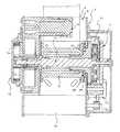
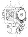
図1は、本発明にかかるシートベルトリトラクタの実施の形態の一例を備えるシートベルト装置を模式的に示す図、図2は、図1に示す例のシートベルトリトラクタを模式的に示す断面図、図3は、図1に示す例のシートベルトリトラクタの動力伝達機構を示す斜視図である。Hereinafter, embodiments for carrying out the present invention will be described with reference to the drawings.
FIG. 1 is a diagram schematically illustrating a seat belt device including an example of an embodiment of a seat belt retractor according to the present invention, and FIG. 2 is a cross-sectional view schematically illustrating the seat belt retractor of the example illustrated in FIG. 3 is a perspective view showing a power transmission mechanism of the seat belt retractor of the example shown in FIG.
図1に示すように、この例のシートベルト装置1は、基本的には従来公知の三点式シートベルト装置と同じである。図中、1はシートベルト装置、2は車両シート、3は車両シート2の近傍に配設されたシートベルトリトラクタ、4はシートベルトリトラクタ3に引き出し可能に巻き取られかつ先端のベルトアンカー4aが車体の床あるいは車両シート2に固定されるシートベルト、5はシートベルトリトラクタ3から引き出されたシートベルト4を乗員のショルダーの方へガイドするガイドアンカー、6はこのガイドアンカー5からガイドされてきたシートベルト4に摺動自在に支持されたタング、7は車体の床あるいは車両シートに固定されかつタング6が係脱可能に挿入係止されるバックルである。
このシートベルト装置1におけるシートベルト4の装着操作および装着解除操作も、従来公知のシートベルト装置と同じである。As shown in FIG. 1, the seat belt device 1 of this example is basically the same as a conventionally known three-point seat belt device. In the figure, 1 is a seat belt device, 2 is a vehicle seat, 3 is a seat belt retractor disposed in the vicinity of the vehicle seat 2, 4 is retractably wound on the seat belt retractor 3, and a
The seatbelt 4 mounting operation and mounting release operation in the seatbelt apparatus 1 are the same as those of a conventionally known seatbelt apparatus.
図2および図3に示すように、この例のシートベルトリトラクタ3は、モータ駆動によるシートベルト4の巻取りおよび引出しをも行うELRであるモータリトラクタ(以下、MSBとも表記する)である(以下、この例のシートベルトリトラクタ3をMSB3とも表記する)。したがって、このMSB3は前述の従来と同様にMSB機能とELR機能とを有する。なお、本発明のシートベルトリトラクタはこれに限定されることはなく、他のMSBで構成することもできるし、また、従来公知のモータ駆動の自動ロック式シートベルトリトラクタ(ALR)で構成することもできる。 As shown in FIGS. 2 and 3, the seat belt retractor 3 of this example is a motor retractor (hereinafter also referred to as MSB) that is an ELR that also winds and pulls out the seat belt 4 driven by a motor. The seat belt retractor 3 in this example is also expressed as MSB3). Therefore, the MSB 3 has an MSB function and an ELR function as in the conventional case. Note that the seat belt retractor of the present invention is not limited to this, and can be constituted by other MSBs, or can be constituted by a conventionally known motor-driven self-locking seat belt retractor (ALR). You can also.
この例のMSB3の基本構成および基本的な作動は、トルクリミッタ機構の構成および作動を除き、特許第4379783号公報に記載されているMSBと同じである。したがって、それらの詳細な説明は特許第4379783号公報を参照すれば容易に理解することができるので省略し、ここでは、これらの同じ構成および作動の部分について簡単に説明する。 The basic configuration and basic operation of the MSB 3 in this example are the same as the MSB described in Japanese Patent No. 4379783 except for the configuration and operation of the torque limiter mechanism. Therefore, the detailed description thereof can be easily understood by referring to Japanese Patent No. 4379783, and is omitted here. The same configuration and operation part will be described briefly here.
図2および図3中、8はフレーム、9はスプール、10は減速度感知機構、11はロック機構、12はトーションバー、13はロッキングベース、14はプリテンショナー、15はスプリングユニット、16はモータ(電動モータ)、18は動力伝達機構、20はパウル、21は内歯である。なお、プリテンショナー14およびモータ16は、いずれも本発明のシートベルトリトラクタの制御装置である電子制御部(ECU)25(後述する図4に示す)により制御される。 2 and 3, 8 is a frame, 9 is a spool, 10 is a deceleration sensing mechanism, 11 is a locking mechanism, 12 is a torsion bar, 13 is a locking base, 14 is a pretensioner, 15 is a spring unit, and 16 is a motor. (Electric motor), 18 is a power transmission mechanism, 20 is a pawl, and 21 is an internal tooth. Note that both the
この例のMSB3の基本的な作動について説明する。
シートベルト4の非装着状態では、スプリングユニット15のスプリング15aの付勢力でスプール9がシートベルト巻取り方向に付勢されることにより、シートベルト4はその全量またはほぼ全量(シートベルト4の非装着状態で、巻取り可能な量)がスプール9に巻き取られている。The basic operation of the MSB 3 in this example will be described.
When the seat belt 4 is not attached, the spool 9 is urged in the seat belt winding direction by the urging force of the
装着のためシートベルト4が通常の速度で引っ張られると、スプール9がシートベルト引出し方向に回転し、シートベルト4が引き出される。タング6がバックル7に挿入係止されることで、シートベルト4が乗員に装着される。また、タング6がバックル7に挿入係止されることで、バックルスイッチ27(後述する図4に示す)がオンし、ECU25はバックルスイッチ27からのオン信号により、モータ16を駆動可能状態にする。そして、モータ16が駆動されて余分に引き出されたシートベルト4がスプール9に乗員が圧
迫感を抱かない程度に巻き取られる。これにより、シートベルト4の弛みが除去されるとともに,乗員がシートベルトによって圧迫されないコンフォート状態となる。When the seat belt 4 is pulled at a normal speed for mounting, the spool 9 rotates in the seat belt pull-out direction, and the seat belt 4 is pulled out. When the tongue 6 is inserted and locked to the
前述の緊急時の初期にはプリテンショナー14が作動してシートベルト巻取りトルクを発生し、このシートベルト巻取りトルクにより、スプール9がシートベルト4を所定量巻き取り、シートベルト4の弛みが除去される。これにより、シートベルト4が乗員を迅速に拘束する。一方、緊急時に発生する大きな車両減速度で減速度感知機構10が作動してロック機構11が作動する。すなわち、ロック機構11のパウル20が回動して、フレーム8の側壁の内歯21に係止する。つまり、この例のシートベルトリトラクタ3のELR機能が作動する。 In the initial stage of the emergency, the
すると、ロッキングベース13のシートベルト引出し方向の回転が阻止(ロック)される。しかし、乗員の慣性でシートベルト4に引出し力が作用してスプール9がベルト引出し方向に回転しようとするので、トーションバー12がねじられ、スプール9のみがシートベルト引出し方向にロッキングベース13に対して相対回転する。これ以後、スプール9がトーションバー12をねじりつつシートベルト引出し方向に回転する。そして、トーションバー12のねじりトルクによって、乗員の衝撃エネルギが吸収緩和されてシートベルト4に加えられる荷重が制限される。 Then, the rotation of the locking
スプール9がロッキングベース13に対してシートベルト引出し方向に所定量相対回転すると、スプール9もロッキングベース13に対して相対回転しなくなる。つまり、スプール9のシートベルト引出し方向の回転がロックされ、シートベルト4は引き出されなくなり、乗員はシートベルト4によって拘束されて慣性移動が阻止される。 When the spool 9 rotates relative to the locking
一方、通常のシートベルト装着状態(バックルスイッチオン状態)で、ECU25はシートベルト4のベルト張力を制御するために、悪路走行や凍結路走行等の車両走行状況、および高速走行、スポーツ走行や急ブレーキ作動等の車両運転状況等のMSB機能の作動条件の内容に基づいてモータ16を制御する。すなわち、モータ16がスプール9のシートベルト巻取り方向に対応する回転方向に駆動されると、モータ16の動力は、動力伝達機構18、およびトーションバー12を介してスプール9に伝達される。これにより、スプール9がシートベルト巻取り方向に回転してシートベルト4が巻き取られ、ベルト張力が大きくなる。 On the other hand, in the normal seatbelt wearing state (buckle switch on state), the
また、モータ16が逆にスプール9のシートベルト引出し方向に対応する回転方向に駆動されると、モータ16の動力は、同様にしてスプール9に伝達され、スプール9がシートベルト引出し方向に回転する。これにより、シートベルト4が引き出されて、ベルト張力が小さくなる。 On the other hand, when the
次に、特許第4379783号公報に記載のMSBと異なるこの例のMSB3の構成および作動について説明する。
この例のMSB3はトルクリミッタ機構を備えていない。また、この例のMSB3の制御装置は、モータ16のシートベルト巻取り方向およびシートベルト引出し方向の回転制御を、前述のMSB機能の作動条件の内容に基づいてモータ16に流れるモータ電流およびモータ電流の流れる向きを制御することにより行っている。Next, the configuration and operation of the MSB 3 of this example different from the MSB described in Japanese Patent No. 4379783 will be described.
The MSB 3 in this example does not include a torque limiter mechanism. In addition, the control device of the MSB 3 in this example controls the rotation of the
図4は、図1に示す例のシートベルトリトラクタの制御装置のブロック図である。
図4に示すように、この例のMSB3の制御装置は、更に、モータ16に電力を供給するための電源22と、電源22から電力を供給制御してモータ16を駆動するドライバ23と、モータ16に流れるモータ電流を測定する電流計24とを有する。ドライバ23および電流計24は、ともにシートベルト装置1の制御装置である電子制御部(ECU)2
5に電気的に接続されている。そして、ECU25によりドライバ23がオン、オフ制御されるとともに、電流計24で測定されたモータ16に流れる電流値をECU25に出力する。ECU25はメモリ25aを有する。このメモリ25aには、MSB機能の作動条件の内容に応じて予め設定された設定電流値、およびモータ16の動力によるシートベルト巻取り開始後からの経過時間の比較基準値として予め設定された設定時間が格納されている。FIG. 4 is a block diagram of the control device for the seat belt retractor of the example shown in FIG.
As shown in FIG. 4, the control device of the MSB 3 of this example further includes a
5 is electrically connected. The driver 23 is controlled to be turned on and off by the
更に、ECU25には、MSB機能の作動条件信号出力部26およびタング・バックル係止検知部材であるバックルスイッチ27が電気的に接続されている。MSB機能の作動条件信号出力部26には、例えば障害物検知センサ、スポーツ走行モードや高速走行モード等の車両運転モード情報信号出力部、衝突予知センサ、衝突検知センサ等が設けられる。 Further, the
MSB機能の作動条件信号出力部26はMSB機能の作動信号をECU25に出力する。ECU25は、このMSB機能の作動信号に基づいてMSB機能の作動条件の成立を判断するとともに、MSB機能の作動条件が成立したと判断したときMSB3のMSB機能を作動する。すなわち、ECU25はモータ16をモータ電流の制御により駆動して、シートベルト4の巻取りおよび引出しを選択的に行う。また、バックルスイッチ27は、タング6がバックル7に挿入係止されたことを検知してオンとなりバックルスイッチオン信号をECU25に出力するとともに、タング6がバックル7から係止解除したときオフとなってバックルスイッチオフ信号をECU25に出力する。ECU25は、このバックルスイッチオン・オフ信号に基づいて乗員のシートベルト装着あるいは非装着を判断する。更に、電流計24はモータ電流を検出してその検出信号をECU25に出力する。 The MSB function operating condition
そして、この例のMSB3の制御装置は、ECU25がバックルスイッチオン状態でかつMSB機能の作動によるシートベルト巻取り時で乗員に慣性力が働く可能性があると判断したときかまたは乗員に慣性力が働いたと判断したときに、動力伝達機構18に入力される荷重が従来のトルクリミッタ機構が作動するトルクリミッタ荷重FL(N)と同等の
トルクリミッタ同等荷重に到達しないようにしている。そして、動力伝達機構18に入力される荷重の制御は、ECU5がモータ16に流れるモータ電流を制御することにより、予め設定された設定電流値に基づいて行われる。その場合、設定電流値は、モータによって所定のシートベルト巻取り荷重を発生させているときの動力伝達機構の荷重に対応して予め設定され、従来のトルクリミッタに設けられているトルクリミッタ機構のトルクリミッタ荷重と同等のトルクリミッタ同等荷重に対応した値よりも小さい。The control device for the MSB 3 in this example determines whether there is a possibility that the inertial force is applied to the occupant when the
なお、この例のMSB3の説明では、MSB機能が作動するとは、モータ16によりスプール9を回転させることにより、シートベルト4を巻取りあるいは引出し動作を行う機能が作動することをいう。また、ELR機能の作動とは、前述のように減速度感知機構10の作動によるロック機構11のパウル20のロック作動をいう。 In the description of the MSB 3 in this example, the operation of the MSB function means that the function of winding or pulling out the seat belt 4 is operated by rotating the spool 9 by the
この例のMSB3の制御装置では、例えば自車の前方に位置する障害物(前方車両等)に対して自車が衝突する可能性があるが衝突回避に余裕があり、自車が障害物に単に接近しつつあるだけであるとECU25が判断したとき、運転者等の乗員に警報する警報動作を行うためにモータ16によりシートベルト4を比較的弱く巻き取る場合、スポーツ走行モードや高速走行モード等における乗員を通常走行モード時のほとんど拘束しない状態から軽く拘束するためにモータ16によりシートベルト4を比較的弱く巻き取る場合、衝突予知センサ等からの出力信号により、自車が前方に位置する障害物(前方車両等)にかなり接近してきて衝突回避に余裕がなく衝突する可能性が高いとECUが判断したとき、運転者等の乗員に警報する警報動作を行いかつ乗員をある程度の大きな拘束力で拘束する緊急動作を行うためにシートベルト4を比較的強く巻き取る場合、衝突検知センサ等からの
出力信号により、自車が障害物(前方車両等)に衝突したとECUが判断した場合等に、MSB機能の作動条件が成立したとしている。In the control device of the MSB 3 in this example, for example, there is a possibility that the own vehicle may collide with an obstacle (front vehicle etc.) located in front of the own vehicle, but there is a margin for avoiding the collision, and the own vehicle becomes an obstacle. When the
乗員に対する警報動作および乗員を軽く拘束するためのシートベルト4の弱い巻取り動作では、ブレーキによる減速度が車両に加えられなく、乗員に慣性力が働かない。また、乗員を大きな拘束力で拘束するためのシートベルト4の強い巻取り動作では、ブレーキによる減速度が車両に加えられる可能性が高く、乗員に慣性力が働く可能性がある。更に、自車が障害物(前方車両等)に衝突した場合は、衝突等による大きな減速度が車両に加えられ、乗員に大きな慣性力が働く。そして、この例のMSB3の制御装置では、このように乗員に大きな慣性力が働いたときは、モータ16への通電が停止されるようになっている。その場合、モータ16への通電停止は、モータ電流が前述の設定電流値になったときに行われる。したがって、モータ16への通電が停止されたときは、動力伝達機構18に入力される荷重は従来のトルクリミッタに設けられているトルクリミッタ機構のトルクリミッタ荷重と同等のトルクリミッタ同等荷重よりも小さい。これにより、モータ16によるシートベルト4の巻取りが行われない(つまり、モータ16の動力が動力伝達機構18に作用しない)ので、動力伝達機構18には従来のトルクリミッタ荷重以上の荷重は入力されない。こうして、シートベルト装着時(バックルスイッチオン時)に動力伝達機構18に入力される荷重が制御される。その結果、モータ16によるシートベルト4の巻取り時に、動力伝達機構18およびモータ16は、シートベルト4からの大きな荷重(カウンタ力)から保護される。このように、乗員に大きな慣性力が働いてモータ16への通電が停止された後は、ELR機能が作動して、スプール9のシートベルト巻取り方向の回転がロックされる。これにより、乗員はシートベルト4で効果的に拘束される。 In the warning operation for the occupant and the weak winding operation of the seat belt 4 for lightly restraining the occupant, the deceleration by the brake is not applied to the vehicle, and the inertia force does not act on the occupant. Further, in the strong winding operation of the seat belt 4 for restraining the occupant with a large restraining force, there is a high possibility that deceleration due to the brake is applied to the vehicle, and inertia force may act on the occupant. Further, when the own vehicle collides with an obstacle (such as a preceding vehicle), a large deceleration due to the collision or the like is applied to the vehicle, and a large inertial force acts on the occupant. And in the control apparatus of MSB3 of this example, when a big inertia force acts on a passenger | crew in this way, electricity supply to the
次に、前述のモータ電流の制御による動力伝達機構18の荷重制御方法について説明する。図5は、動力伝達機構の荷重制御方法のフローを示す図である。
動力伝達機構18の荷重制御にあたっては、図5に示すようにステップS1でタング6がバックル7に挿入係止されてバックルスイッチ27がオンされる。バックルスイッチ27がオンになると、ステップS2でECU25によりシートベルト4の巻取りのためのMSB機能の作動条件が成立したか否かが判断される。MSB機能の作動条件が成立したと判断されると、ステップS3でモータ16への通電が行われて、シートベルト4の巻取りが開始される。シートベルト4の巻取りにより、ステップS4でモータ16のモータ電流が上昇する。Next, a load control method for the
In controlling the load of the
次いで、ステップS5で乗員に慣性力が働く可能性があるか否か、または乗員に慣性力が働いたか否かが判断される。乗員に慣性力が働く可能性がないとともに乗員に慣性力が働いていないと判断されると、ステップS6でMSB機能の作動条件が解消したか否かが判断される。MSB機能の作動条件が解消したと判断されると、ステップS7でモータ16への通電が停止されるとともに、ステップS8でMSB機能の作動が解除される。このときのMSB機能の作動解除は、モータ16がシートベルト引出し方向に回転して、動力伝達機構18のクラッチが解放(切断)される。そして、シートベルト4が乗員に対する初期の通常装着状態(乗員に対してシートベルトによる圧迫感のないコンフォート状態)に復帰される。次いで、ステップS9でバックルスイッチ27がオフになったか否かが判断される。バックルスイッチ27がオフになったと判断されると、動力伝達機構18の荷重制御が終了し、シートベルトの装着が解除される。 Next, in step S5, it is determined whether there is a possibility that inertial force is applied to the occupant or whether inertial force is applied to the occupant. If it is determined that there is no possibility that inertial force is applied to the occupant and no inertial force is applied to the occupant, it is determined in step S6 whether or not the operating condition of the MSB function has been eliminated. When it is determined that the operation condition of the MSB function has been eliminated, the energization to the
ステップS6でMSB機能の作動条件が解消していないと判断されると、ステップS10でMSB作動条件が解消していなくても、モータ16への通電が停止可能であるか否かが判断される。このステップS10の処理では、例えば前述のように乗員に対する警報を行うためにシートベルト4を比較的弱く巻き取る場合、その警報を設定時間以上に長く続ける必要がないときは、モータ16への通電を停止するようにしている。これにより、モ
ータ16への駆動時間が短縮されてモータ16の寿命が長くなるとともに、消費電力が低減する。MSB作動条件が解消していなくても、モータ16への通電が停止可能であると判断されると、ステップS11で設定時間が満了(経過)したか否かが判断される。設定時間が満了(経過)していないと判断されると、このステップS11の処理が繰り返される。設定時間が満了(経過)したと判断されると、ステップS7に移行してこのステップS7以降の処理が行われる。ステップS10でMSB作動条件が解消していない中で、モータ16への通電が停止可能でないと判断されると、ステップS5に移行してこのステップS5以降の処理が行われる。If it is determined in step S6 that the operating condition of the MSB function has not been eliminated, it is determined in step S10 whether or not the energization to the
ステップS5で乗員に慣性力が働く可能性があるかまたは乗員に慣性力が働いたと判断されると、ステップS12でモータ電流が設定電流値以上であるか否かが判断される。モータ電流が設定電流値以上であると判断されると、ステップS13でモータ16への通電が停止されるとともに、ステップS14でELR機能が作動する。したがって、パウル20が内歯21に係止してスプール9のシートベルト引出し方向の回転がロックされる。こうして、衝突時等の車両に大きな減速度が加えられたときには、乗員はシートベルト4により効果的に拘束される。このとき、車両に大きな減速度が加えられると、乗員の慣性力でシートベルト4から大きな荷重(カウンタ力)が動力伝達機構18に入力されようとするが、この例のMSB3ではELR機能の作動により、動力伝達機構18には大きな荷重は入力されない。その後、ステップS8へ移行し、このステップS8以降の処理が行われる。このときのMSB機能の作動解除は、まずモータ16がシートベルト巻取り方向に回転してELR機能の動作におけるパウル20と内歯21との係止を解除し、その後前述と同様にモータ16がシートベルト引出し方向に回転して、動力伝達機構18のクラッチが解放(切断)される。ステップS12でモータ電流が設定電流値以上でないと判断されるステップS6に移行してこのステップS6以降の処理が行われる。ステップS2でMSB機能の作動条件が成立していないと判断されると、ステップS9に移行してこのステップS9以降の処理が行われる。ステップS9でバックルスイッチ27がオフになっていないと判断されると、ステップS2に移行してこのステップS2以降の処理が行われる。
こうして、この例のMSB3ではトルクリミッタ機構が設けられなくても、モータ16への通電を制御することにより動力伝達機構18には大きな荷重が入力されず、動力伝達機構18およびモータ16が保護される。If it is determined in step S5 that there is a possibility that inertial force is applied to the occupant or inertial force is applied to the occupant, it is determined in step S12 whether or not the motor current is equal to or greater than the set current value. If it is determined that the motor current is greater than or equal to the set current value, energization of the
Thus, even if the torque limiter mechanism is not provided in the MSB 3 of this example, a large load is not input to the
この例のシートベルトリトラクタ3の制御装置によれば、動力伝達機構18に入力される荷重を制限するトルクリミッタ機構を備えていない。また、この例のシートベルトリトラクタ3の制御装置によれば、ECU25がバックルスイッチ27がオンでMSB機能の作動条件が成立したと判断したとき、MSB機能が作動し、シートベルト4が巻き取られる。そして、更にECU25はシートベルト4の巻取り状態で乗員に慣性力が働く可能性が生じたと判断したときか、あるいは乗員に慣性力が働いたと判断したときで、モータ電流が、モータによって所定のシートベルト巻取り荷重を発生させているときの動力伝達機構の荷重に対応して予め設定され、従来のトルクリミッタに設けられているトルクリミッタ機構のトルクリミッタ荷重と同等のトルクリミッタ同等荷重に対応した値よりも小さい設定電流値以上になったと判断したとき、モータ16への通電を停止する。したがって、動力伝達機構18に入力される荷重をトルクリミッタ同等荷重以下に制限することが可能となる。こうして、この例のMSB3によれば、トルクリミッタ機構が設けられなくても、乗員のシートベルト装着状態でモータ16への通電を制御することにより、動力伝達機構18を効果的に保護することができる。すなわち、トルクリミッタ機構が不要となる。 According to the control device for the seat belt retractor 3 of this example, the torque limiter mechanism for limiting the load input to the
そして、トルクリミッタ機構を備えていないので、動力伝達機構18における動力伝達構造をより簡単にできるとともに、動力伝達系全体をより小型に形成することができる。したがって、動力伝達系のコストを削減することができ、その結果、MSB3全体のコストを低減することができる。 Since the torque limiter mechanism is not provided, the power transmission structure in the
一方、この例のシートベルトリトラクタ3の制御装置を備えるシートベルト装置1によれば、トルクリミッタ機構を備えないことから、シートベルトリトラクタ3もコンパクトに形成することができ、車室内のシートベルトリトラクタ3の配設自由度を向上できる。 On the other hand, according to the seat belt device 1 having the control device for the seat belt retractor 3 of this example, since the torque limiter mechanism is not provided, the seat belt retractor 3 can also be formed in a compact manner, and the seat belt retractor in the passenger compartment. 3 can be improved.
なお、本発明のシートベルトリトラクタの制御装置は前述の実施の形態の例に限定されることはなく、特許請求の範囲に記載された技術事項の範囲内で種々の設計変更が可能である。 The seatbelt retractor control device of the present invention is not limited to the above-described embodiment, and various design changes can be made within the scope of the technical matters described in the claims.
本発明のシートベルトリトラクタの制御装置およびこれを備えたシートベルト装置は、モータの動力を動力伝達機構を介してスプールに伝達することでシートベルトの巻取りおよび引出しを行うモータリトラクタとして構成され、シートベルトからの所定以上の大きな荷重(カウンタ力)から動力伝達機構を保護するシートベルトリトラクタの制御装置およびこれを備えたシートベルト装置の技術分野に関するものである。 The seatbelt retractor control device of the present invention and the seatbelt device provided with the seatbelt retractor are configured as a motor retractor that winds and pulls out the seatbelt by transmitting the power of the motor to the spool via the power transmission mechanism, The present invention relates to a control device for a seat belt retractor that protects a power transmission mechanism from a large load (counter force) more than a predetermined value from a seat belt, and a technical field of a seat belt device including the same.
1…シートベルト装置、3…シートベルトリトラクタ、4…シートベルト、6…タング、7…バックル、8…フレーム、9…スプール、10…減速度感知機構、11…ロック機構、12…トーションバー、13…ロッキングベース、14…プリテンショナー、15…スプリングユニット、16…モータ(電動モータ)、18…動力伝達機構、19…トルクリミッタ機構、20…パウル、24…電流計、25…電子制御部(ECU)、26…MSB機能の作動条件信号出力部、27…バックルスイッチDESCRIPTION OF SYMBOLS 1 ... Seat belt apparatus, 3 ... Seat belt retractor, 4 ... Seat belt, 6 ... Tongue, 7 ... Buckle, 8 ... Frame, 9 ... Spool, 10 ... Deceleration sensing mechanism, 11 ... Locking mechanism, 12 ... Torsion bar, DESCRIPTION OF
Claims (2)
Translated fromJapaneseタングとバックルとの係止を検知するタング・バックル係止検知部材と、
前記モータの動力を前記シートベルトを巻き取るスプールに伝達する動力伝達機構と、
前記モータに流れるモータ電流を検知する電流計と、
前記シートベルト張力制御機能の作動条件信号を出力するシートベルト張力制御機能作動条件信号出力部と、
前記モータへの通電を制御する制御部とを少なくとも備え、
前記制御部は、前記タング・バックル係止検知部材がタングとバックルとの係止を検知しかつ前記シートベルト張力制御機能作動条件信号出力部からの出力信号に基づいて前記シートベルト張力制御機能が作動していると判断した状態で、前記シートベルト張力制御機能作動条件信号出力部からの出力信号に基づいて乗員に慣性力が働く可能性が生じたと判断したときあるいは乗員に慣性力が働いたと判断したときで、前記電流計で検知された前記モータのモータ電流が予め設定された設定電流値以上になったと判断したとき、前記モータへの通電を停止することを特徴とするシートベルトリトラクタの制御装置。Control for controlling a seat belt retractor having an emergency lock function for locking the withdrawal of the seat belt by a lock mechanism in an emergency and a seat belt tension control function for winding and withdrawing the seat belt at the time of tension control of the seat belt by a motor In the device
A tongue and buckle locking detection member for detecting locking between the tongue and the buckle;
A power transmission mechanism for transmitting the power of the motor to a spool that winds up the seat belt;
An ammeter for detecting a motor current flowing through the motor;
A seat belt tension control function operation condition signal output unit for outputting an operation condition signal of the seat belt tension control function;
A control unit that controls energization to the motor,
The control unit detects the locking of the tongue and the buckle by the tongue / buckle locking detection member, and the seat belt tension control function is based on an output signal from the seat belt tension control function operating condition signal output unit. When it is determined that there is a possibility of inertial force acting on the occupant based on the output signal from the seat belt tension control function operation condition signal output unit, or when the inertial force acts on the occupant When it is determined, when it is determined that the motor current of the motor detected by the ammeter is equal to or higher than a preset current value, the energization to the motor is stopped. Control device.
前記シートベルトリトラクタは請求項1に記載のシートベルトリトラクタであり、
前記シートベルトリトラクタの制御装置は請求項1に記載のシートベルトリトラクタの制御装置であることを特徴とするシートベルト装置。A seat belt retractor control device comprising a seat belt retractor that winds up a seat belt and a control unit that controls the seat belt retractor, and a tongue that is slidably supported by the seat belt drawn from the seat belt retractor; A seat belt device comprising at least a buckle on which the tongue is releasably locked, and restrains an occupant by the seat belt;
The seat belt retractor is a seat belt retractor according to claim 1,
The seat belt retractor control device according to claim 1, wherein the seat belt retractor control device is a seat belt retractor control device.
Priority Applications (1)
| Application Number | Priority Date | Filing Date | Title |
|---|---|---|---|
| JP2010103898AJP2011230690A (en) | 2010-04-28 | 2010-04-28 | Control device of seat belt retractor, and seat belt device including the same |
Applications Claiming Priority (1)
| Application Number | Priority Date | Filing Date | Title |
|---|---|---|---|
| JP2010103898AJP2011230690A (en) | 2010-04-28 | 2010-04-28 | Control device of seat belt retractor, and seat belt device including the same |
Publications (1)
| Publication Number | Publication Date |
|---|---|
| JP2011230690Atrue JP2011230690A (en) | 2011-11-17 |
Family
ID=45320456
Family Applications (1)
| Application Number | Title | Priority Date | Filing Date |
|---|---|---|---|
| JP2010103898AWithdrawnJP2011230690A (en) | 2010-04-28 | 2010-04-28 | Control device of seat belt retractor, and seat belt device including the same |
Country Status (1)
| Country | Link |
|---|---|
| JP (1) | JP2011230690A (en) |
Cited By (2)
| Publication number | Priority date | Publication date | Assignee | Title |
|---|---|---|---|---|
| CN104155495A (en)* | 2013-05-13 | 2014-11-19 | 苏州工业园区新宏博通讯科技有限公司 | Commercial power and oil engine power meter |
| CN104251927A (en)* | 2013-06-28 | 2014-12-31 | 苏州工业园区新宏博通讯科技有限公司 | Oil machine mains electricity meter software implementing method and oil machine mains electricity meter |
- 2010
- 2010-04-28JPJP2010103898Apatent/JP2011230690A/ennot_activeWithdrawn
Cited By (2)
| Publication number | Priority date | Publication date | Assignee | Title |
|---|---|---|---|---|
| CN104155495A (en)* | 2013-05-13 | 2014-11-19 | 苏州工业园区新宏博通讯科技有限公司 | Commercial power and oil engine power meter |
| CN104251927A (en)* | 2013-06-28 | 2014-12-31 | 苏州工业园区新宏博通讯科技有限公司 | Oil machine mains electricity meter software implementing method and oil machine mains electricity meter |
Similar Documents
| Publication | Publication Date | Title |
|---|---|---|
| JP2011230691A (en) | Control device of seat belt retractor, and seat belt device including the same | |
| US6726249B2 (en) | Motorized seat belt retractor | |
| US20070114775A1 (en) | Seat belt apparatus | |
| US7726693B2 (en) | Motor retractor and drive control thereof | |
| EP1777127B1 (en) | Seat belt retractor, seat belt apparatus, and vehicle with seat belt apparatus | |
| CN1891538B (en) | Seat belt retractors, seat belt assemblies and vehicles with seat belt assemblies | |
| JP2004262259A (en) | Seat belt equipment | |
| US20070046015A1 (en) | Seat belt apparatus and vehicle | |
| JP2007001534A (en) | Seat belt retractor, seat belt device and vehicle with seat belt device | |
| JP4644549B2 (en) | Seat belt retractor, seat belt device, vehicle with seat belt device | |
| JP4705058B2 (en) | Motor driven seat belt device | |
| JP2001347923A (en) | Motorized seat belt retractor | |
| JP4714525B2 (en) | Seat belt retractor, seat belt device, vehicle with seat belt device | |
| JP2001253317A (en) | Seat belt system | |
| JP2007176423A (en) | Seat belt retractor, seat belt device, and vehicle having seat belt device | |
| EP1445155A1 (en) | Seat belt system | |
| JP2011230690A (en) | Control device of seat belt retractor, and seat belt device including the same | |
| JP5086889B2 (en) | Seat belt retractor | |
| KR101211107B1 (en) | A seat belt for controlling a webbing winding motor by an occupant's volume | |
| JP2007083883A (en) | Seat belt control device of vehicle | |
| JP5557697B2 (en) | Seat belt device | |
| JP5531051B2 (en) | Seat belt retractor | |
| JP2009298382A (en) | Occupant crash protection device | |
| JP4722619B2 (en) | Vehicle seat belt device | |
| JP4838059B2 (en) | Seat belt device |
Legal Events
| Date | Code | Title | Description |
|---|---|---|---|
| A300 | Withdrawal of application because of no request for examination | Free format text:JAPANESE INTERMEDIATE CODE: A300 Effective date:20130702 |