JP2011229612A - Electric rice cooker and inner pot for bread maker - Google Patents
Electric rice cooker and inner pot for bread makerDownload PDFInfo
- Publication number
- JP2011229612A JP2011229612AJP2010101119AJP2010101119AJP2011229612AJP 2011229612 AJP2011229612 AJP 2011229612AJP 2010101119 AJP2010101119 AJP 2010101119AJP 2010101119 AJP2010101119 AJP 2010101119AJP 2011229612 AJP2011229612 AJP 2011229612A
- Authority
- JP
- Japan
- Prior art keywords
- rice cooker
- bread
- inner pot
- rice
- cooking
- Prior art date
- Legal status (The legal status is an assumption and is not a legal conclusion. Google has not performed a legal analysis and makes no representation as to the accuracy of the status listed.)
- Granted
Links
Images


Classifications
- A—HUMAN NECESSITIES
- A47—FURNITURE; DOMESTIC ARTICLES OR APPLIANCES; COFFEE MILLS; SPICE MILLS; SUCTION CLEANERS IN GENERAL
- A47J—KITCHEN EQUIPMENT; COFFEE MILLS; SPICE MILLS; APPARATUS FOR MAKING BEVERAGES
- A47J43/00—Implements for preparing or holding food, not provided for in other groups of this subclass
- A47J43/04—Machines for domestic use not covered elsewhere, e.g. for grinding, mixing, stirring, kneading, emulsifying, whipping or beating foodstuffs, e.g. power-driven
- A47J43/046—Machines for domestic use not covered elsewhere, e.g. for grinding, mixing, stirring, kneading, emulsifying, whipping or beating foodstuffs, e.g. power-driven with tools driven from the bottom side
- A47J43/0465—Machines for domestic use not covered elsewhere, e.g. for grinding, mixing, stirring, kneading, emulsifying, whipping or beating foodstuffs, e.g. power-driven with tools driven from the bottom side with magnetic drive
Landscapes
- Engineering & Computer Science (AREA)
- Mechanical Engineering (AREA)
- Food Science & Technology (AREA)
- Baking, Grill, Roasting (AREA)
- Food-Manufacturing Devices (AREA)
- Cookers (AREA)
Abstract
Description
Translated fromJapaneseこの発明は、炊飯だけでなく製パンも可能な電気炊飯器およびその電気炊飯器で使用される製パン用内鍋に関する。 The present invention relates to an electric rice cooker capable of not only cooking rice but also bread making and an inner pan for bread making used in the electric rice cooker.
従来、炊飯機能と製パン機能の両方を備えた製パン機能付き炊飯器が提案されている(特許文献1(特開2008−18122号公報),特許文献2(特開2004−261247号公報)参照)。この製パン機能付き炊飯器は、製パン時にモータによって練り羽根を回転させて容器内でパン材料を練り混ぜてパン生地を生成している。 Conventionally, a rice cooker with a bread making function having both a rice cooking function and a bread making function has been proposed (Patent Document 1 (Japanese Patent Laid-Open No. 2008-18122), Patent Document 2 (Japanese Patent Laid-Open No. 2004-261247)). reference). This rice cooker with a bread-making function produces bread dough by rotating kneading blades with a motor during bread making and kneading bread ingredients in a container.
しかし、上記製パン機能付き炊飯器では、モータの回転トルクを伝達する回転軸が容器の底部を貫通している。このため、回転軸と容器との間に水漏れを防ぐためのシール部を設けても、炊飯を繰り返しているうちにシール部の経時劣化が生じて炊飯時に貫通箇所から水漏れが発生し易くなるという問題がある。 However, in the rice cooker with a bread-making function, the rotating shaft that transmits the rotational torque of the motor penetrates the bottom of the container. For this reason, even if a seal part for preventing water leakage is provided between the rotating shaft and the container, the sealing part is deteriorated with time while cooking rice, and water leakage is likely to occur from the penetration portion during cooking. There is a problem of becoming.
一方、水漏れを回避するためには、モータの回転トルクをマグネットカップリングにより練り羽根に伝達することも考えられる。 On the other hand, in order to avoid water leakage, it is also conceivable to transmit the rotational torque of the motor to the kneading blades using a magnet coupling.
しかし、この場合は、パン材料を練り混ぜるのに必要な回転トルクを得るためにはマグネットが大型化し、炊飯時の邪魔になるとともに製品も大型化してしまうという問題がある。 However, in this case, in order to obtain the rotational torque necessary to knead the bread ingredients, there is a problem that the magnet is enlarged, which becomes an obstacle during cooking and the product is also enlarged.
そこで、この発明の課題は、炊飯時の水漏れを防止できて大型化を招くことなく製パンも可能にできる電気炊飯器および製パン用内鍋を提供することにある。 Then, the subject of this invention is providing the electric rice cooker which can prevent the water leak at the time of rice cooking, and can also bread-making without causing enlargement, and the inner pot for bread-making.
上記課題を解決するため、この発明の電気炊飯器は、被加熱物を収容する炊飯用内鍋と、
上記炊飯用内鍋が収納される炊飯器本体と、
上記炊飯器本体の上部に開閉自在に取り付けられ、上記炊飯用内鍋を覆うように閉じることが可能な蓋体と、
上記炊飯用内鍋内に回転自在に配置され、被駆動側磁石を有する撹拌体と、
上記炊飯用内鍋外に配置され、上記撹拌体を回転駆動する回転駆動装置と、
上記炊飯器本体に収納された上記炊飯用内鍋を加熱する加熱部と
を備え、
上記回転駆動装置は、
駆動モータと、
上記駆動モータの回転軸に取り付けられ、上記被駆動側磁石と磁気カップリングする駆動側磁石を有すると共に上記駆動モータが駆動されることで上記撹拌体を回転駆動するための回転磁界を発生させる回転磁界発生部と、
上記駆動モータの回転軸に取り付けられており、上記炊飯用内鍋に替えて製パン用内鍋が上記炊飯器本体に収納されたときに、上記製パン用内鍋内に回転自在に配置されたパンこね部材に取り付けられた被駆動部材に機械的に連結されて、上記駆動モータの回転トルクを上記被駆動部材に機械的に直接伝達する機械的連結部と
を有することを特徴としている。In order to solve the above problems, an electric rice cooker of the present invention includes an inner pot for cooking rice that accommodates an object to be heated,
A rice cooker body in which the inner pot for cooking rice is stored;
A lid that is attached to the top of the rice cooker body so as to be freely opened and closed, and can be closed so as to cover the inner pot for rice cooking,
A stirrer that is rotatably arranged in the inner cooking pot and has a driven magnet,
Rotation drive device that is arranged outside the inner pot for cooking rice and rotationally drives the agitator,
A heating part for heating the inner pot for cooking rice stored in the rice cooker body,
The rotational drive device is
A drive motor;
Rotation that is attached to the rotation shaft of the drive motor, has a drive-side magnet that is magnetically coupled to the driven-side magnet, and generates a rotating magnetic field for driving the agitator by rotating the drive motor. A magnetic field generator,
It is attached to the rotating shaft of the drive motor, and when the inner pan for bread making is stored in the rice cooker body instead of the inner pan for rice cooking, it is rotatably arranged in the inner pan for bread making. And a mechanical coupling portion that is mechanically coupled to a driven member attached to the bread kneading member and mechanically directly transmits the rotational torque of the drive motor to the driven member.
この発明の電気炊飯器によれば、炊飯時には、上記炊飯用内鍋を炊飯器本体に収納し、上記加熱部で炊飯用内鍋を加熱し、上記駆動モータが駆動されることで、上記回転駆動装置が回転磁界を発生させ、上記炊飯用内鍋内の撹拌体の被駆動側磁石との磁気カップリングにより、撹拌体が非接触で回転駆動される。これにより、撹拌体を回転駆動するための回転駆動装置が炊飯用内鍋を貫通する必要がなく、水漏れを起こすことなく、被加熱物(米と水等)が撹拌されて温度を均一にできると共に米に吸水させることができる。 According to the electric rice cooker of this invention, at the time of rice cooking, the above-mentioned inner pot for rice cooking is stored in the rice cooker main body, the inner pot for rice cooking is heated by the above heating unit, and the above drive motor is driven so that the above rotation is performed. The drive device generates a rotating magnetic field, and the stirrer is rotationally driven in a non-contact manner by magnetic coupling with the driven magnet of the stirrer in the inner pot for rice cooking. This eliminates the need for a rotational drive device for rotationally driving the stirrer to pass through the inner pot for cooking rice, causing the water to be heated (rice and water, etc.) to be stirred and the temperature to be uniform without causing water leakage. Can be made to absorb water with rice.
一方、製パン時に、上記炊飯用内鍋に替えて、上記被駆動部材に取り付けられパンこね部材を有する製パン用内鍋を上記炊飯器本体に収納することができる。これにより、上記製パン用内鍋の上記被駆動部材が上記回転駆動装置の機械的連結部に機械的に連結されて上記機械的連結部から上記駆動モータの回転トルクが上記被駆動部材に機械的に直接伝達される。したがって、磁気カップリングに比べて、大きな回転トルクで上記パンこね部材を回転させることができ、回転トルクが不足することなくパン材料を充分に練り混ぜてパン生地を生成できる。 On the other hand, instead of the above-mentioned inner pot for rice cooking at the time of bread making, the inner pot for bread making having a bread kneading member attached to the driven member can be accommodated in the rice cooker body. Accordingly, the driven member of the inner pan for bread making is mechanically connected to the mechanical connecting portion of the rotation driving device, and the rotational torque of the drive motor is mechanically applied to the driven member from the mechanical connecting portion. Transmitted directly. Therefore, the bread kneading member can be rotated with a large rotational torque as compared with the magnetic coupling, and the bread dough can be produced by sufficiently kneading the bread material without insufficient rotational torque.
なお、パンこねは常温で行われるため、炊飯に比べると水漏れは起こりにくいので、シール部材によって水漏れを防止可能となる。また、一般に、製パンの頻度は炊飯の頻度に比べて低いから、上記シール部材の経時劣化も抑えられる。 In addition, since bread kneading is performed at room temperature, water leakage is less likely to occur compared to rice cooking, and thus water leakage can be prevented by the sealing member. Moreover, since the frequency of bread making is generally lower than the frequency of rice cooking, deterioration of the seal member over time can be suppressed.
また、一実施形態の電気炊飯器は、上記炊飯器本体に上記炊飯用内鍋に替えて収納され、上記加熱部により加熱可能な製パン用内鍋を備え、
上記製パン用内鍋は、
内鍋本体と、
上記内鍋本体に回転自在に取り付けられていると共に上記内鍋本体が上記炊飯器本体に収納されたときに上記機械的連結部に連結されて上記駆動モータの回転トルクが上記機械的連結部から機械的に直接伝達される被駆動部材と、
上記被駆動部材に取り付けられたパンこね部材と
を有する。Moreover, the electric rice cooker of one embodiment is stored in the rice cooker body in place of the inner cooking pot, and includes an inner pan for baking that can be heated by the heating unit,
The inner pan for bread making is
The inner pot body,
When the inner pot body is rotatably attached to the inner pot body and the inner pot body is housed in the rice cooker body, it is connected to the mechanical connecting portion, and the rotational torque of the drive motor is generated from the mechanical connecting portion. A driven member that is mechanically transmitted directly;
A bread kneading member attached to the driven member.
この実施形態の電気炊飯器によれば、上記炊飯用内鍋に替えて、上記製パン用内鍋を上記炊飯器本体に収納することで、パンこね部材に取り付けられた被駆動部材に、上記駆動モータに取り付けられた機械的連結部が連結され、上記駆動モータの回転トルクが上記被駆動部材に機械的に直接伝達される。したがって、磁気カップリングに比べて、大きな回転トルクでパンこね部材を回転させることができる。また、上記加熱部により、上記製パン用内鍋を加熱してパンを焼き上げることができる。 According to the electric rice cooker of this embodiment, instead of the inner pot for rice cooking, the driven member attached to the bread kneading member is accommodated in the rice cooker body by storing the inner pot for bread making, the above-mentioned A mechanical connecting portion attached to the drive motor is connected, and the rotational torque of the drive motor is mechanically transmitted directly to the driven member. Therefore, the bread kneading member can be rotated with a large rotational torque as compared with the magnetic coupling. Moreover, the said bread | pan can be baked by heating the said inner pot for baking with the said heating part.
また、一実施形態の電気炊飯器は、上記炊飯器本体に取り付けられていると共に、上記炊飯器本体に上記炊飯用内鍋が収納されているときに上記炊飯用内鍋の温度を検出し、上記炊飯器本体に上記製パン用内鍋が収納されているときに上記製パン用内鍋の温度を検出する温度センサとを備え、
上記温度センサの検知面に接触する上記製パン用内鍋の被検知面の形状を、上記温度センサの検知面に接触する上記炊飯用内鍋の被検知面の形状と略同じ形状にした。Moreover, while the electric rice cooker of one Embodiment is attached to the said rice cooker main body, when the said inner pot for rice cooking is accommodated in the said rice cooker main body, the temperature of the said inner pot for rice cooking is detected, A temperature sensor that detects the temperature of the bread-making inner pan when the bread-making inner pan is stored in the rice cooker body;
The shape of the detected surface of the inner bread pan for contact with the detection surface of the temperature sensor was made substantially the same as the shape of the detected surface of the inner pot for rice cooking that was in contact with the detection surface of the temperature sensor.
この実施形態の電気炊飯器によれば、炊飯時と製パン時の両方において、上記温度センサを共用して、上記温度センサで炊飯用内鍋と製パン用内鍋の温度を正確に検出できる。 According to the electric rice cooker of this embodiment, the temperature sensor can be shared in both the time of rice cooking and the time of bread making, and the temperature of the inner pot for rice cooking and the inner pot for bread making can be accurately detected by the temperature sensor. .
また、この発明の製パン用内鍋は、内鍋本体と、
上記内鍋本体に回転自在に取り付けられていると共に上記内鍋本体が炊飯器本体に収納されたときに駆動モータの磁気カップリング用の駆動用磁石を有する回転軸に取り付けられた機械的連結部に機械的に連結されて、上記駆動モータの回転トルクが上記機械的連結部から機械的に直接伝達される被駆動部材と、
上記被駆動部材に取り付けられたパンこね部材と
を有する。Moreover, the inner pot for bread making of the present invention comprises an inner pot body,
A mechanical connecting portion attached to a rotating shaft that is rotatably attached to the inner pot body and has a driving magnet for magnetic coupling of a drive motor when the inner pot body is stored in the rice cooker body. A driven member that is mechanically coupled to the rotational torque of the drive motor and mechanically directly transmitted from the mechanical coupling portion;
A bread kneading member attached to the driven member.
この製パン用内鍋によれば、上記炊飯器本体に収納することにより、上記パンこね部材に取り付けられている被駆動部材が上記駆動モータの回転軸に取り付けられた機械的連結部に連結される。この機械的連結部は、上記パンこね部材に取り付けられている被駆動部材に駆動モータの回転トルクを機械的に直接伝達するので、磁気カップリングに比べて、大きな回転トルクでパンこね部材を回転させることができる。 According to this bread making pan, the driven member attached to the bread kneading member is connected to the mechanical connecting part attached to the rotating shaft of the drive motor by being housed in the rice cooker body. The Since this mechanical connection part mechanically transmits the rotational torque of the drive motor directly to the driven member attached to the bread kneading member, it rotates the bread kneading member with a larger rotational torque than the magnetic coupling. Can be made.
また、一実施形態の製パン用内鍋では、上記炊飯器本体に収納されたときに上記炊飯器本体の内壁に対向する外壁と、
上記外壁の内側に形成されていると共に上記パンこね部材を囲む内壁とを有する。Moreover, in the inner pan for bread making of one embodiment, when stored in the rice cooker body, the outer wall facing the inner wall of the rice cooker body,
And an inner wall that is formed inside the outer wall and surrounds the bread kneading member.
この実施形態の製パン用内鍋によれば、パン材料を内壁内の外径が小さな領域に集めることができるので、パンこね部材を回転させるのに必要なトルクを低減できる。 According to the bread-making inner pot of this embodiment, since the bread material can be collected in a region where the outer diameter of the inner wall is small, the torque required to rotate the bread kneading member can be reduced.
また、一実施形態の製パン用内鍋では、上記内壁は、四角い筒形状である。 Moreover, in the inner pot for bread making of one embodiment, the said inner wall is a square cylinder shape.
この実施形態の製パン用内鍋によれば、上記パンこね部材を回転させたときに、パン材料が内壁に当たり易いので、内壁が円筒形状である場合に比べて、パン生地をこね易くなる。 According to the bread-making inner pot of this embodiment, since the bread material easily hits the inner wall when the bread kneading member is rotated, it becomes easier to knead the bread dough compared to the case where the inner wall is cylindrical.
この発明の電気炊飯器によれば、炊飯時には、炊飯用内鍋を炊飯器本体に収納し、加熱部で炊飯用内鍋を加熱し、駆動モータを駆動することで、回転駆動装置で回転磁界を発生させ、磁気カップリングにより内鍋内の撹拌体を非接触で回転駆動するので、水漏れを起こすことなく被加熱物(米と水等)を撹拌できて温度を均一にできると共に米に吸水させることができる。 According to the electric rice cooker of this invention, at the time of rice cooking, the inner pot for rice cooking is stored in the rice cooker body, the inner pot for rice cooking is heated by the heating unit, and the drive motor is driven to rotate the magnetic field with the rotation drive device. Since the stirrer in the inner pot is rotated in a non-contact manner by magnetic coupling, the heated object (rice and water, etc.) can be stirred without causing water leakage, and the temperature can be made uniform. Can absorb water.
一方、製パン時には、上記炊飯用内鍋に替えて、被駆動部材に連結されたパンこね部材を有する製パン用内鍋を炊飯器本体に収納することにより、上記製パン用内鍋の上記被駆動部材が上記回転駆動装置の機械的連結部に接続されて上記機械的連結部から上記駆動モータの回転トルクが上記被駆動部材に機械的に直接伝達される。したがって、磁気カップリングに比べて、大きな回転トルクで上記パンこね部材を回転させることができ、回転トルクの不足を招くことなく、パン材料を練り混ぜてパン生地を生成できる。 On the other hand, at the time of bread making, the above-mentioned inner pot for bread making is stored in the rice cooker body by storing the inner pot for bread making having the bread kneading member connected to the driven member instead of the inner pot for rice cooking. The driven member is connected to the mechanical connecting portion of the rotational driving device, and the rotational torque of the driving motor is mechanically transmitted directly from the mechanical connecting portion to the driven member. Therefore, the bread kneading member can be rotated with a large rotational torque as compared with the magnetic coupling, and the bread dough can be produced by mixing the bread ingredients without causing a shortage of the rotational torque.
以下、この発明を図示の実施の形態により詳細に説明する。 Hereinafter, the present invention will be described in detail with reference to the illustrated embodiments.
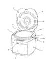
図1はこの発明の実施の一形態の電気炊飯器を斜め上方から見た斜視図を示している。 FIG. 1: has shown the perspective view which looked at the electric rice cooker of one Embodiment of this invention from diagonally upward.
この実施の一形態の電気炊飯器は、図1に示すように、炊飯器本体1と、炊飯器本体1に開閉自在に取り付けられた蓋体2とを備えている。炊飯器本体1は、前面側に設けられた表示操作部3と、前面側かつ上側に設けられたフックボタン4と、後面側に回動自在に取り付けられた本体ハンドル5と、後面側かつ下側に接続された電源コード6とを有する。また、蓋体2の後面側に蒸気口2aを設けている。表示操作部3は、液晶ディスプレイと複数の操作ボタンにより構成され、調理メニューや調理状況などの表示とボタン操作が可能である。蓋体2は、炊飯器本体1に設けられたラッチ機構(図示せず)により係脱可能に係止された状態で閉じられており、フックボタン4を押すことによりラッチ機構が外れて、スプリング26(図3に示す)の付勢力で蓋体2が開く。 As shown in FIG. 1, the electric rice cooker of this embodiment includes a rice cooker body 1 and a
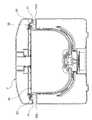
また、図2は上記電気炊飯器の蓋体2を開いた状態の斜視図を示しており、図1と同一の構成部には同一参照番号を付している。 Moreover, FIG. 2 has shown the perspective view of the state which opened the
この電気炊飯器は、図2に示すように、炊飯器本体1の上側かつ後面側に設けられたヒンジ軸20(図3に示す)を介して蓋体2を上下方向に回動自在に支持している。この蓋体2は、外蓋21と内蓋22とを有する。また、炊飯器本体1内に被加熱物を収容する炊飯用内鍋10を収納している。 As shown in FIG. 2, this electric rice cooker supports the
上記炊飯用内鍋10の上側開口の縁に環状のフランジ部10aを設けている。その炊飯用内鍋10のフランジ部10aの半径方向に対向する位置に、耐熱樹脂製の内鍋把手11,11を取り付けている。炊飯器本体1の上面の左右2箇所に、位置決め部の一例としての凹部12a(図2では右側のみを示す)を設けて、この2つの凹部12aに炊飯用内鍋10の内鍋把手11,11が夫々嵌合する。これにより、炊飯器本体1に収納された炊飯用内鍋10が炊飯器本体1に対して位置決めされる。 An
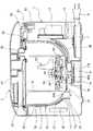
図3は図1のIII−III線から見た電気炊飯器の縦断面図を示しており、図3に示すように、炊飯器本体1は、外ケース12と、その外ケース12内に配置され、炊飯用内鍋10を収納する内ケース13とを有する。内ケース13は、耐熱性と電気絶縁性を有する材料で形成されている。 FIG. 3 shows a longitudinal sectional view of the electric rice cooker viewed from the line III-III in FIG. 1, and as shown in FIG. 3, the rice cooker body 1 is arranged in the
上記外ケース12と内ケース13との間の空間の後面側(図3の右側)に、電源回路やインバータ回路などを含む電源部14を配置し、電源部14の下側に電源部14などを冷却する冷却ファン15を配置している。さらに、冷却ファン15の下側かつ外ケース12の底部に、電源コード6を巻き取るコードリール7を配置している。 A
また、炊飯用内鍋10の底部に、内側に突出する円筒形状の凸部10bを設けている。この炊飯用内鍋10の凸部10bに円板形状の撹拌翼40を回転自在に嵌合している。この撹拌翼40は、環状のヨーク41と、そのヨーク41の内側に周方向かつ等間隔に配列された被駆動側磁石としての複数の磁石42とを有する。この炊飯用内鍋10の凸部10bに対向する内ケース13の領域に開口部13aを設けている。この開口部13aは、上記凸部10bに沿って突出した内ケース13の突出部13bに形成されている。 Moreover, the cylindrical
そして、炊飯用内鍋10の凸部10bの下側かつ内ケース13の突出部13bの内側に、駆動側磁石としての複数の磁石18が周方向かつ等間隔に配置された頭部16bを有する回転磁界発生部であるロータ16を配置している。頭部16bは嵌合部44を有し、この嵌合部44は上記開口部13aで上記突出部13bから露出している。ロータ16の頭部16bが機械的連結部を構成している。また、このロータ16の軸部16aに回転軸17aが連結された駆動モータとしての撹拌モータ17を炊飯用内鍋10の底部の下側に配置している。 And it has the
なお、撹拌モータ17,ロータ16は回転駆動装置の一例である。また、図3の90は、ロータ16の軸部16aを囲むカバーである。カバー90とロータ16との間にシール部を設けてもよい。 The
そして、ロータ16と撹拌翼40は、夫々の磁石18,42によりラジアル型の磁気カップリングにより連結され、撹拌モータ17により駆動されたロータ16が回転することにより、磁気カップリングを介して撹拌翼40が回転する。 The
また、外ケース12と内ケース13との間の空間の前面側(図3の左側)に、表示操作部3(図1,図2に示す)と電源部14のインバータ回路と冷却ファン15および撹拌モータ17などを制御する制御部30を配置している。 Further, on the front side of the space between the
また、炊飯器本体1内の内ケース13の下側かつ外側に、炊飯用内鍋10を誘導加熱するための誘導コイル31を配置している。この誘導コイル31は、耐熱性を有する樹脂などにより内ケース13の外面に接着されている。また、誘導コイル31の下側には、誘導コイル31の漏れ磁束を防止するフェライト部材38を配置している。さらに、炊飯器本体1内の内ケース13の上側の側面を囲むように横ヒータ32を周方向に沿って配置している。また、内ケース13の下側に内ケース13を貫通する底温度センサ33を配置している。この底温度センサ33は、内ケース13に収納された炊飯用内鍋10の底部近傍の被検知面10cに先端部の検知面33aが接触して、炊飯用内鍋10の温度を検出する。なお、蓋体2内に蓋ヒータ39(図4に示す)と蓋温度センサ34(図5に示す)を配置している。 Moreover, the
上記誘導コイル31と横ヒータ32および蓋ヒータ39で炊飯用内鍋10全体を加熱する加熱部を構成している。 The
上記炊飯用内鍋10は、例えばアルミニウムなどの高熱伝導部材で形成され、その外面に加熱効率を向上させる例えばステンレス等の磁性体を貼り付ける一方、内面に被加熱物の付着を防ぐためのフッ素樹脂をコーティングしている。 The
一方、上記蓋体2は、炊飯器本体1の上側かつ後面側に設けられたヒンジ軸20(図3に示す)を介して蓋体2が回動自在に支持された外蓋21と、その外蓋21の炊飯用内鍋10に対向する側に着脱自在に取り付けられた内蓋22とを有する。この内蓋22の外周に環状の耐熱ゴム製のパッキン23を着脱自在に取り付けている。蓋体2が閉じられたときにパッキン23は、炊飯用内鍋10のフランジ部10aの上面に密着して、炊飯用内鍋10と内蓋22との間をシールする。また、図3において、24は内蓋22に設けられた蒸気穴である。 On the other hand, the
図4は図1のIV−IV線から見た電気炊飯器の縦断面図を示しており、図4に示すように、炊飯器本体1の外ケース12の上面の左右2箇所に設けられた凹部12a,12aに、炊飯用内鍋10の内鍋把手11,11を嵌合させると、炊飯用内鍋10は炊飯器本体1に対して位置決めされる。 FIG. 4 shows a vertical cross-sectional view of the electric rice cooker as viewed from the line IV-IV in FIG. 1. As shown in FIG. 4, the electric rice cooker is provided at two left and right positions on the upper surface of the
そして、上記内鍋把手11内には磁石50を埋め込んでいる。また、外蓋21の磁石50上に位置する部分に、蓋体2を閉じたときに磁石50の磁気によりオンする磁気センサとしてのリードスイッチ25を取り付けている。なお、内鍋把手11,11のどちらにも磁石50を埋め込んでいる。また、上記磁気センサとして、ホール素子を用いてもよい。 A
図5は上記電気炊飯器の制御ブロック図を示している。上記制御部30は、マイクロコンピュータと入出力回路などからなり、表示操作部3からの操作信号や、リードスイッチ25,底温度センサ33,蓋温度センサ34からの信号などに基づいて、表示操作部3,撹拌モータ17,冷却ファン15,誘導コイル用インバータ回路35,横ヒータ用回路36および蓋ヒータ用回路37を制御する。誘導コイル用インバータ回路35は、誘導コイル31に交番磁界を発生させる。上記誘導コイル用インバータ回路35,横ヒータ用回路36,蓋ヒータ用回路37は、電源部14(図3に示す)に含まれている。 FIG. 5 shows a control block diagram of the electric rice cooker. The
上記構成の電気炊飯器によれば、適量の米と水を入れた炊飯用内鍋10を炊飯器本体1内に収納した後、使用者が表示操作部3を操作して、加熱調理(炊飯)を開始すると、制御部30は、リードスイッチ25がオンか否かを判定する。すなわち、炊飯器本体1内に炊飯用内鍋10が収納された状態で蓋体2が閉じられているか否かを判定する。そして、制御部30がリードスイッチ25がオンしていると判定すると、誘導コイル31,横ヒータ32,蓋ヒータ39を制御して加熱調理(炊飯)を開始する。一方、制御部30がリードスイッチ25がオンしていないと判定すると、加熱調理を開始しない。このとき、表示操作部3に炊飯器本体1内に炊飯用内鍋10が収納された状態で蓋体2が閉じられていないことを表示してもよい。 According to the electric rice cooker of the said structure, after accommodating the rice cooker
この加熱調理運転では、制御部30は、予熱運転モード、立ち上げ運転モード、炊き上げ運転モード、蒸らし運転モード、保温運転モードの順に制御を行う。 In this cooking operation, the
〔予熱運転モード〕
まず、予熱運転モードでは、撹拌モータ17により撹拌翼40を回転駆動して、炊飯用内鍋10内を撹拌しながら、誘導コイル用インバータ回路35から誘導コイル31に小電力を供給して、誘導コイル31により炊飯用内鍋10を誘導加熱し、底温度センサ33により検出された炊飯用内鍋10内の温度を60℃に保つように誘導コイル31の電力を制御して、予熱運転を所定時間行う。このとき、撹拌翼40により炊飯用内鍋10内を撹拌することにより、炊飯用内鍋10内の被加熱物(米と水)を均一な目標温度(60℃)に保った状態で米に吸水させて、うまみ成分であるグルコースを生成する。[Preheating operation mode]
First, in the preheating operation mode, the agitating
この予熱運転モードでは、澱粉分解酵素が最も有効に働く温度である60℃に設定されており、15分〜20分の間、炊飯用内鍋10内の温度を60℃に保つ。この実施の形態では、予熱運転モードの目標温度を60℃としたが、これに限らず、目標温度は諸条件に応じて適宜設定すればよい。 In this preheating operation mode, it is set to 60 ° C., which is the temperature at which the amylolytic enzyme works most effectively, and the temperature in the
〔立ち上げ運転モード〕
次に、撹拌モータ17の運転を停止して撹拌翼40を止めた後、誘導コイル用インバータ回路35から誘導コイル31に大電力を供給して、誘導コイル31により炊飯用内鍋10を誘導加熱すると共に、横ヒータ用回路36,蓋ヒータ用回路37を制御して、横ヒータ32,蓋ヒータ39により炊飯用内鍋10を側方と上側から加熱し、炊飯用内鍋10内の温度を100℃に立ち上げる立ち上げ運転を行う。ここで、炊飯用内鍋10内の温度は、底温度センサ33と蓋温度センサ34により検出する。[Start-up operation mode]
Next, after the operation of the
〔炊き上げ運転モード〕
次に、炊飯用内鍋10内の温度が100℃に達してから炊飯用内鍋10内の温度が120℃になるまで、誘導コイル31と横ヒータ32および蓋ヒータ39による加熱量を調整して沸騰を維持した炊き上げ運転を行う。ここで、炊飯用内鍋10内の水が無くなって沸騰しなくなると、炊飯用内鍋10内の温度が100℃から上昇し始める。[Cooking operation mode]
Next, the heating amount by the
上記炊き上げ運転によって、米に熱と水が加わって米に含まれるβ澱粉がα澱粉へと変化する糊化という化学反応が起こり、美味しいご飯ができる。 By the above cooking operation, heat and water are added to the rice to cause a chemical reaction called gelatinization in which β starch contained in the rice is changed to α starch, and delicious rice can be produced.
〔蒸らし運転モード〕
そうして、炊飯用内鍋10内の温度が120℃に達すると、誘導コイル31と横ヒータ32および蓋ヒータ39による加熱量を調整して蒸らし運転を所定時間行った後、加熱調理(炊飯)を終了して、保温運転モードに移る。[Steaming operation mode]
Then, when the temperature in the
このように、この実施形態の電気炊飯器によれば、炊飯時に、炊飯用内鍋10が炊飯器本体1に装着され、撹拌モータ17が駆動されることで、ロータ16の磁石18が回転磁界を発生させ、撹拌翼40の磁石42との磁気カップリングにより、撹拌翼40が非接触で回転駆動される。これにより、水漏れを起こすことなく、被加熱物(米と水等)が撹拌されて温度を均一にできると共に米に吸水させることができる。 Thus, according to the electric rice cooker of this embodiment, the
次に、図6を参照して、上記電気炊飯器で製パンを行う場合に、炊飯用内鍋10に替えて、炊飯器本体1に収納される製パン用内鍋60を説明する。図6は、図1のIII−III線から見た電気炊飯器の縦断面図に相当している。 Next, with reference to FIG. 6, when bread-making with the said electric rice cooker, it replaces with the rice cooker
この製パン用内鍋60は、例えばアルミニウムなどの高熱伝導部材で形成され、その外面に加熱効率を向上させる例えばステンレス等の磁性体を貼り付ける一方、内面に被加熱物の付着を防ぐためのフッ素樹脂をコーティングしている。この製パン用内鍋60は、内鍋本体61の底部61aに回転自在に設けられた被駆動部材としての嵌合回転部材62と、嵌合回転部材62に連結されたパンこね羽根63とを有する。底部61aと嵌合回転部材62との間にはシール部材64,65を含むシール部68が配置されている。嵌合回転部材62は、炊飯器本体1のロータ16の機械的連結部としての頭部16bの嵌合部44に嵌合する嵌合部66を有する。炊飯器本体1に製パン用内鍋60を収納すると、製パン用内鍋60の嵌合回転部材62の嵌合部66が、炊飯器本体1のロータ16の嵌合部44に、相対回転不可に噛合される。この嵌合部66と嵌合部44との嵌合によって、製パン用内鍋60の嵌合回転部材62が炊飯器本体1のロータ16に相対回転不可に機械的に連結される。なお、嵌合部66と嵌合部44とは、セレーション嵌合によって相対回転不可に嵌合されるものでもよく、非円柱形状の凸部と非円柱形状の凹部との嵌合もしくは多角柱形状の凸部と多角柱形状の凹部との嵌合によって相対回転不可に嵌合されるものでもよい。 The
また、製パン用内鍋60は、底温度センサ33の検知面33aに沿って接触する被検知面60cを有する。底温度センサ33で製パン用内鍋60の温度が検出される。製パン用内鍋60の被検知面60cの形状を、炊飯用内鍋10の被検知面10cの形状と同じ形状にしたので、底温度センサ33で製パン用内鍋60の温度を正確に検出でき、炊飯時と製パン時の両方において底温度センサ33を共用できる。また、製パン用内鍋60は、上側開口の縁に環状のフランジ部60aを設けている。その製パン用内鍋10のフランジ部10aの半径方向に対向する位置に、耐熱樹脂製の内鍋把手(図示せず)を取り付けている。この内鍋把手は、図4に示す炊飯用内鍋10の内鍋把手11と同様であり、炊飯器本体1の位置決め部としての凹部12aに嵌合する。また、この内鍋把手は、炊飯用内鍋10の内鍋把手11の磁石50と同様の磁石(図示せず)が埋め込まれていて、蓋体2を閉じたときに上記磁石の磁気によりリードスイッチ25がオンする。 Moreover, the
次に、図6に示すように、製パン用内鍋60を炊飯器本体1に収納した電気炊飯器で製パンを行う動作を説明する。まず、パン材料(水,小麦等)を入れた製パン用内鍋60を炊飯器本体1に収納した後、使用者が表示操作部3を操作して、製パンを開始させる。すると、制御部30はリードスイッチ25がオンか否かを判定する。すなわち、炊飯器本体1内に製パン用内鍋60が収納された状態で蓋体2が閉じられているか否かを判定する。そして、制御部30がリードスイッチ25がオンしていると判定すると、撹拌モータ17を駆動する。これにより、ロータ16が回転し、ロータ16の嵌合部44に相対回転不可に嵌合している嵌合部66が回転して、嵌合回転部材62,パンこね羽根63が回転することで、パン材料が練り混ぜられて、パン生地が生成される。 Next, as shown in FIG. 6, the operation | movement which bread-produces with the electric rice cooker which accommodated the
撹拌モータ17を予め定められた時間だけ駆動して、パン生地の生成が終了すると、制御部30は、撹拌モータ17を停止し、次の発酵処理が開始される。この発酵処理では、誘導コイル用インバータ回路35から誘導コイル31に電力を供給して、誘導コイル31により製パン用内鍋60を誘導加熱すると共に、横ヒータ用回路36,蓋ヒータ用回路37を制御して、横ヒータ32,蓋ヒータ39により製パン用内鍋60を側方と上側から加熱し、製パン用内鍋60内の温度が発酵温度に制御される。ここで、製パン用内鍋60内の温度は、底温度センサ33と蓋温度センサ34により検出する。この発酵処理によって、パン生地が発酵すると、パン生地を焼き上げる焼成処理へ移り、誘導コイル31,横ヒータ32,蓋ヒータ39により製パン用内鍋60がより高い焼き温度に加熱される。ここで、製パン用内鍋60は、底部61aが底部61a以外の部分に比べて肉厚に成形されていて、所望の焼き温度が保持される。こうして、パンが焼き上がったら、誘導コイル31と横ヒータ32および蓋ヒータ39による加熱量を低減して保温運転モードに移る。 When the stirring
このように、この実施形態の電気炊飯器によれば、製パン時に、製パン用内鍋60を炊飯器本体1に装着することで、製パン用内鍋60のパンこね羽根63に連結している嵌合回転部材62の嵌合部66がロータ16の嵌合部44に相対回転不可に嵌合される。よって、ロータ16に嵌合回転部材62が機械的に直結されるので、撹拌モータ17は、磁気カップリングに比べて、パンこね羽根63を大きなトルクで回転駆動でき、回転トルクが不足することなくパン材料を充分に練り混ぜてパン生地を生成することが可能になる。 Thus, according to the electric rice cooker of this embodiment, by attaching the bread making
したがって、この実施形態によれば、炊飯時の水漏れを防ぎながら製パンも可能にできる。 Therefore, according to this embodiment, it is possible to make bread while preventing water leakage during cooking.
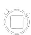
次に、図7,図8を参照して、上記製パン用内鍋60の変形例を説明する。図7は、この変形例の製パン用内鍋70を炊飯器本体1に収納した状態を示す断面図である。また、図8は、製パン用内鍋70を上方から下方に見た平面図である。この製パン用内鍋70は、内鍋本体71が内壁72と外壁73を有する点だけが前述の製パン用内鍋60と異なる。よって、この製パン用内鍋70は、前述の製パン用内鍋60と同様の部分には同様の符号を付している。なお、図8では、パンこね羽根63を省略している。 Next, with reference to FIG. 7, FIG. 8, the modification of the said bread-making
この製パン用内鍋70の外壁73は、炊飯器本体1の内壁をなす内ケース13に沿って対向している。また、内壁72は外壁73の内側に形成されていてパンこね羽根63を囲んでいる。 The
この製パン用内鍋70によれば、パン材料を内壁72内の外径が小さな領域に集めることができるので、パンこね羽根63を回転させるのに必要なトルクを低減できる。また、加熱時には、誘導コイル31と横ヒータ32によって、まず、外壁73が加熱され、この外壁73から外壁73と内壁72間の空間の空気を経由して内壁72に伝熱されるので、内壁72は間接的に加熱されることとなり、均一に加熱され易くなって、パン生地を均一に加熱することができる。 According to this bread-making
また、この製パン用内鍋70は、前述の製パン用内鍋60と同様、底温度センサ33の検知面33aに沿って接触する被検知面70cを有する。底温度センサ33で製パン用内鍋70の温度が検出される。製パン用内鍋70の被検知面70cの形状を、炊飯用内鍋10の被検知面10cの形状と同じ形状にしたので、底温度センサ33で製パン用内鍋70の温度を正確に検出でき、炊飯時と製パン時の両方において底温度センサ33を共用できる。また、この製パン用内鍋70は、前述の製パン用内鍋60と同様、上側開口の縁に環状のフランジ部70aを設けている。この製パン用内鍋70のフランジ部70aの半径方向に対向する位置に、耐熱樹脂製の内鍋把手(図示せず)を取り付けている。この内鍋把手は、図4に示す炊飯用内鍋10の内鍋把手11と同様であり、炊飯器本体1の位置決め部としての凹部12aに嵌合する。また、この内鍋把手は、炊飯用内鍋10の内鍋把手11の磁石50と同様の磁石(図示せず)が埋め込まれていて、蓋体2を閉じたときに上記磁石の磁気によりリードスイッチ25がオンする。 In addition, the bread-making
また、図8に示すように、内壁72を四角い筒形状にしたので、パンこね羽根63を回転させたときに、パン材料が内壁72に当たり易く、内壁72が円筒形状である場合に比べて、パン生地をこね易くなる。なお、内壁72の形状は四角い筒形状に限らないのは勿論で円筒形状,楕円の筒形状,多角形の筒形状であってもよい。 Further, as shown in FIG. 8, since the
尚、上記実施形態では、機械的連結部としてのロータ16の嵌合部44と製パン用内鍋の被駆動部材としての嵌合回転部材62の嵌合部66とが相対回転不可に嵌合するものとしたが、上記機械的連結部と被駆動部材を歯車とし、互いに噛合する2つの歯車によるギア機構で回転トルクを伝達するようにしてもよい。また、上記実施形態において、誘導コイル31の換わりに、横ヒータ32と同様のヒータを用いてもよい。このヒータを用いる場合、炊飯用内鍋10,製パン用内鍋60,70の高熱伝導部材の外面に磁性体を貼り付けなくてもよい。 In the above embodiment, the
この発明の具体的な実施の形態について説明したが、この発明は上記実施の形態に限定されるものではなく、この発明の範囲内で種々変更して実施することができる。 Although specific embodiments of the present invention have been described, the present invention is not limited to the above embodiments, and various modifications can be made within the scope of the present invention.
1…炊飯器本体
2…蓋体
2a…蒸気口
3…表示操作部
4…フックボタン
5…本体ハンドル
6…電源コード
7…コードリール
10…炊飯用内鍋
10a…フランジ部
10b…凸部
10c…被検知面
11…内鍋把手
12…外ケース
12a…凹部
13…内ケース
13a…開口部
13b…突出部
14…電源部
15…冷却ファン
16…ロータ
16a…軸部
16b…頭部
17…撹拌モータ
17a…回転軸
18…磁石
20…ヒンジ軸
21…外蓋
22…内蓋
23…パッキン
24…蒸気穴
25…リードスイッチ
26…スプリング
30…制御部
31…誘導コイル
32…横ヒータ
33…底温度センサ
33a…検知面
34…蓋温度センサ
35…誘導コイル用インバータ回路
36…横ヒータ用回路
37…蓋ヒータ用回路
38…フェライト部材
39…蓋ヒータ
40…撹拌翼
41…ヨーク
42…磁石
44…嵌合部
50…磁石
60…製パン用内鍋
60a…フランジ部
60c…被検知面
61…内鍋本体
61a…底部
62…嵌合回転部材
63…パンこね羽根
64,65…シール部材
66…嵌合部
68…シール部
70…製パン用内鍋
70a…フランジ部
70c…被検知面
71…内鍋本体
72…内壁
73…外壁DESCRIPTION OF SYMBOLS 1 ... Rice cooker
Claims (6)
Translated fromJapanese上記炊飯用内鍋が収納される炊飯器本体と、
上記炊飯器本体の上部に開閉自在に取り付けられ、上記炊飯用内鍋を覆うように閉じることが可能な蓋体と、
上記炊飯用内鍋内に回転自在に配置され、被駆動側磁石を有する撹拌体と、
上記炊飯用内鍋外に配置され、上記撹拌体を回転駆動する回転駆動装置と、
上記炊飯器本体に収納された上記炊飯用内鍋を加熱する加熱部と
を備え、
上記回転駆動装置は、
駆動モータと、
上記駆動モータの回転軸に取り付けられ、上記被駆動側磁石と磁気カップリングする駆動側磁石を有すると共に上記駆動モータが駆動されることで上記撹拌体を回転駆動するための回転磁界を発生させる回転磁界発生部と、
上記駆動モータの回転軸に取り付けられており、上記炊飯用内鍋に替えて製パン用内鍋が上記炊飯器本体に収納されたときに、上記製パン用内鍋内に回転自在に配置されたパンこね部材に取り付けられた被駆動部材に機械的に連結されて、上記駆動モータの回転トルクを上記被駆動部材に機械的に直接伝達する機械的連結部と
を有することを特徴とする電気炊飯器。An inner pot for cooking rice that houses the object to be heated;
A rice cooker body in which the inner pot for cooking rice is stored;
A lid that is attached to the top of the rice cooker body so as to be freely opened and closed, and can be closed so as to cover the inner pot for rice cooking,
A stirrer that is rotatably arranged in the inner cooking pot and has a driven magnet,
Rotation drive device that is arranged outside the inner pot for cooking rice and rotationally drives the agitator,
A heating part for heating the inner pot for cooking rice stored in the rice cooker body,
The rotational drive device is
A drive motor;
Rotation that is attached to the rotation shaft of the drive motor, has a drive-side magnet that is magnetically coupled to the driven-side magnet, and generates a rotating magnetic field for driving the agitator by rotating the drive motor. A magnetic field generator,
It is attached to the rotating shaft of the drive motor, and when the inner pan for bread making is stored in the rice cooker body instead of the inner pan for rice cooking, it is rotatably arranged in the inner pan for bread making. And a mechanical coupling portion that is mechanically coupled to a driven member attached to the bread kneading member and mechanically directly transmits the rotational torque of the drive motor to the driven member. rice cooker.
上記炊飯器本体に上記炊飯用内鍋に替えて収納され、上記加熱部により加熱可能な製パン用内鍋を備え、
上記製パン用内鍋は、
内鍋本体と、
上記内鍋本体に回転自在に取り付けられていると共に上記内鍋本体が上記炊飯器本体に収納されたときに上記機械的連結部に連結されて上記駆動モータの回転トルクが上記機械的連結部から機械的に直接伝達される被駆動部材と、
上記被駆動部材に取り付けられたパンこね部材と
を有することを特徴とする電気炊飯器。In the electric rice cooker according to claim 1,
The rice cooker body is housed in place of the inner pot for cooking rice, and includes an inner pot for bread making that can be heated by the heating unit,
The inner pan for bread making is
The inner pot body,
When the inner pot body is rotatably attached to the inner pot body and the inner pot body is housed in the rice cooker body, it is connected to the mechanical connecting portion, and the rotational torque of the drive motor is generated from the mechanical connecting portion. A driven member that is mechanically transmitted directly;
An electric rice cooker comprising a bread kneading member attached to the driven member.
上記炊飯器本体に取り付けられていると共に、上記炊飯器本体に上記炊飯用内鍋が収納されているときに上記炊飯用内鍋の温度を検出し、上記炊飯器本体に上記製パン用内鍋が収納されているときに上記製パン用内鍋の温度を検出する温度センサを備え、
上記温度センサの検知面に接触する上記製パン用内鍋の被検知面の形状を、上記温度センサの検知面に接触する上記炊飯用内鍋の被検知面の形状と略同じ形状にしたことを特徴とする電気炊飯器。In the electric rice cooker according to claim 2,
While being attached to the rice cooker body, the temperature of the inner rice cooker is detected when the rice cooker body is housed in the rice cooker body, and the bread cooker in the rice cooker body is detected. Equipped with a temperature sensor that detects the temperature of the inner bread pan when the is stored,
The shape of the detected surface of the inner bread pan for contact with the detection surface of the temperature sensor is made substantially the same shape as the detected surface of the inner pot for rice cooking that contacts the detection surface of the temperature sensor. An electric rice cooker.
上記内鍋本体に回転自在に取り付けられていると共に上記内鍋本体が炊飯器本体に収納されたときに駆動モータの磁気カップリング用の駆動用磁石を有する回転軸に取り付けられた機械的連結部に機械的に連結されて、上記駆動モータの回転トルクが上記機械的連結部から機械的に直接伝達される被駆動部材と、
上記被駆動部材に取り付けられたパンこね部材と
を有することを特徴とする製パン用内鍋。The inner pot body,
A mechanical connecting portion attached to a rotating shaft that is rotatably attached to the inner pot body and has a driving magnet for magnetic coupling of a drive motor when the inner pot body is stored in the rice cooker body. A driven member that is mechanically coupled to the rotational torque of the drive motor and mechanically directly transmitted from the mechanical coupling portion;
An inner pan for baking, comprising a bread kneading member attached to the driven member.
上記炊飯器本体に収納されたときに上記炊飯器本体の内壁に対向する外壁と、
上記外壁の内側に形成されていると共に上記パンこね部材を囲む内壁とを有することを特徴とする製パン用内鍋。In the inner pan for bread making according to any one of claims 2 to 4,
An outer wall facing the inner wall of the rice cooker body when stored in the rice cooker body;
An inner pot for bread making, comprising an inner wall formed inside the outer wall and surrounding the bread kneading member.
上記内壁は、四角い筒形状であることを特徴とする製パン用内鍋。In the inner pan for bread making according to claim 5,
The said inner wall is a square cylinder shape, The inner pot for breadmaking characterized by the above-mentioned.
Priority Applications (1)
| Application Number | Priority Date | Filing Date | Title |
|---|---|---|---|
| JP2010101119AJP5637728B2 (en) | 2010-04-26 | 2010-04-26 | Electric rice cooker |
Applications Claiming Priority (1)
| Application Number | Priority Date | Filing Date | Title |
|---|---|---|---|
| JP2010101119AJP5637728B2 (en) | 2010-04-26 | 2010-04-26 | Electric rice cooker |
Publications (2)
| Publication Number | Publication Date |
|---|---|
| JP2011229612Atrue JP2011229612A (en) | 2011-11-17 |
| JP5637728B2 JP5637728B2 (en) | 2014-12-10 |
Family
ID=45319596
Family Applications (1)
| Application Number | Title | Priority Date | Filing Date |
|---|---|---|---|
| JP2010101119AExpired - Fee RelatedJP5637728B2 (en) | 2010-04-26 | 2010-04-26 | Electric rice cooker |
Country Status (1)
| Country | Link |
|---|---|
| JP (1) | JP5637728B2 (en) |
Cited By (6)
| Publication number | Priority date | Publication date | Assignee | Title |
|---|---|---|---|---|
| JP2014217412A (en)* | 2013-05-01 | 2014-11-20 | 株式会社プロスパイン | Magnetic coupling-type kneader |
| JP2014226350A (en)* | 2013-05-23 | 2014-12-08 | タイガー魔法瓶株式会社 | Home bakery |
| CN110419963A (en)* | 2019-08-28 | 2019-11-08 | 青岛澳柯玛生活电器有限公司 | A kind of magnetic suspension steamed bun bread all-in-one machine |
| US10945557B2 (en) | 2016-06-15 | 2021-03-16 | Panasonic Intellectual Property Management Co., Ltd. | Heating/stirring cooker |
| WO2023029628A1 (en)* | 2021-08-31 | 2023-03-09 | 浙江绍兴苏泊尔生活电器有限公司 | Cooking utensil |
| JP7646511B2 (en) | 2021-09-16 | 2025-03-17 | シャープ株式会社 | Cooking equipment and cooking methods |
Citations (5)
| Publication number | Priority date | Publication date | Assignee | Title |
|---|---|---|---|---|
| JPS63189120U (en)* | 1987-05-26 | 1988-12-05 | ||
| JPH05161546A (en)* | 1991-12-13 | 1993-06-29 | Matsumoto Kokan Kk | Electric pot |
| JPH0685028U (en)* | 1993-05-18 | 1994-12-06 | ホシザキ電機株式会社 | Stirrer |
| JPH09164074A (en)* | 1995-12-14 | 1997-06-24 | Tokyo Gas Co Ltd | Rice cooker with bread making function |
| JP2004261248A (en)* | 2003-02-28 | 2004-09-24 | Hitachi Hometec Ltd | Cooking device |
- 2010
- 2010-04-26JPJP2010101119Apatent/JP5637728B2/ennot_activeExpired - Fee Related
Patent Citations (5)
| Publication number | Priority date | Publication date | Assignee | Title |
|---|---|---|---|---|
| JPS63189120U (en)* | 1987-05-26 | 1988-12-05 | ||
| JPH05161546A (en)* | 1991-12-13 | 1993-06-29 | Matsumoto Kokan Kk | Electric pot |
| JPH0685028U (en)* | 1993-05-18 | 1994-12-06 | ホシザキ電機株式会社 | Stirrer |
| JPH09164074A (en)* | 1995-12-14 | 1997-06-24 | Tokyo Gas Co Ltd | Rice cooker with bread making function |
| JP2004261248A (en)* | 2003-02-28 | 2004-09-24 | Hitachi Hometec Ltd | Cooking device |
Cited By (6)
| Publication number | Priority date | Publication date | Assignee | Title |
|---|---|---|---|---|
| JP2014217412A (en)* | 2013-05-01 | 2014-11-20 | 株式会社プロスパイン | Magnetic coupling-type kneader |
| JP2014226350A (en)* | 2013-05-23 | 2014-12-08 | タイガー魔法瓶株式会社 | Home bakery |
| US10945557B2 (en) | 2016-06-15 | 2021-03-16 | Panasonic Intellectual Property Management Co., Ltd. | Heating/stirring cooker |
| CN110419963A (en)* | 2019-08-28 | 2019-11-08 | 青岛澳柯玛生活电器有限公司 | A kind of magnetic suspension steamed bun bread all-in-one machine |
| WO2023029628A1 (en)* | 2021-08-31 | 2023-03-09 | 浙江绍兴苏泊尔生活电器有限公司 | Cooking utensil |
| JP7646511B2 (en) | 2021-09-16 | 2025-03-17 | シャープ株式会社 | Cooking equipment and cooking methods |
Also Published As
| Publication number | Publication date |
|---|---|
| JP5637728B2 (en) | 2014-12-10 |
Similar Documents
| Publication | Publication Date | Title |
|---|---|---|
| JP4822962B2 (en) | Rice cooker with bread making function | |
| JP5637728B2 (en) | Electric rice cooker | |
| KR100263209B1 (en) | High frequency heating apparatus | |
| WO2011148982A1 (en) | Rice cooker | |
| CN113509065B (en) | Baking attachment for kitchen multifunctional machine | |
| CN102892336B (en) | Rice cooking device | |
| RU154679U1 (en) | MULTIFUNCTIONAL BAKER | |
| JP2011156200A (en) | Electric rice cooker | |
| TWI602532B (en) | Heating conditioner | |
| JP2012125467A (en) | Rice cooker | |
| JP2013165822A (en) | Rice cooker | |
| JP2009039423A (en) | Cooker | |
| JP2011156023A (en) | Electric rice cooker | |
| JP2009039424A (en) | Cooker | |
| JP6405813B2 (en) | Electric cooker | |
| JP6249231B2 (en) | Electric cooker | |
| JP2011240014A (en) | Electric rice cooker | |
| CN107174110B (en) | porridge cooking machine | |
| JP2013113518A (en) | Heating cooker | |
| JP2011156236A (en) | Electric rice cooker | |
| JP2013223597A (en) | Cooker | |
| CN219479844U (en) | Food processor | |
| CN209203041U (en) | Food processing device | |
| JP5947150B2 (en) | Cooker | |
| JP2014140504A (en) | Heating cooker |
Legal Events
| Date | Code | Title | Description |
|---|---|---|---|
| A621 | Written request for application examination | Free format text:JAPANESE INTERMEDIATE CODE: A621 Effective date:20130401 | |
| A977 | Report on retrieval | Free format text:JAPANESE INTERMEDIATE CODE: A971007 Effective date:20140220 | |
| A131 | Notification of reasons for refusal | Free format text:JAPANESE INTERMEDIATE CODE: A131 Effective date:20140304 | |
| A521 | Written amendment | Free format text:JAPANESE INTERMEDIATE CODE: A523 Effective date:20140421 | |
| TRDD | Decision of grant or rejection written | ||
| A01 | Written decision to grant a patent or to grant a registration (utility model) | Free format text:JAPANESE INTERMEDIATE CODE: A01 Effective date:20140924 | |
| A61 | First payment of annual fees (during grant procedure) | Free format text:JAPANESE INTERMEDIATE CODE: A61 Effective date:20141021 | |
| R150 | Certificate of patent or registration of utility model | Ref document number:5637728 Country of ref document:JP Free format text:JAPANESE INTERMEDIATE CODE: R150 | |
| LAPS | Cancellation because of no payment of annual fees |