JP2011223567A - Audio network system and display method - Google Patents
Audio network system and display methodDownload PDFInfo
- Publication number
- JP2011223567A JP2011223567AJP2011064709AJP2011064709AJP2011223567AJP 2011223567 AJP2011223567 AJP 2011223567AJP 2011064709 AJP2011064709 AJP 2011064709AJP 2011064709 AJP2011064709 AJP 2011064709AJP 2011223567 AJP2011223567 AJP 2011223567A
- Authority
- JP
- Japan
- Prior art keywords
- network
- devices
- ring
- audio
- transmission path
- Prior art date
- Legal status (The legal status is an assumption and is not a legal conclusion. Google has not performed a legal analysis and makes no representation as to the accuracy of the status listed.)
- Pending
Links
- 238000000034methodMethods0.000titleclaimsdescription32
- 230000005540biological transmissionEffects0.000claimsdescription277
- 230000005236sound signalEffects0.000claimsdescription85
- 238000011144upstream manufacturingMethods0.000claimsdescription34
- 238000001514detection methodMethods0.000claimsdescription10
- 230000004044responseEffects0.000claimsdescription7
- 230000008878couplingEffects0.000claims1
- 238000010168coupling processMethods0.000claims1
- 238000005859coupling reactionMethods0.000claims1
- 238000012790confirmationMethods0.000abstract1
- 238000012545processingMethods0.000description52
- 230000015654memoryEffects0.000description43
- 230000008569processEffects0.000description16
- 230000008859changeEffects0.000description14
- 238000005070samplingMethods0.000description12
- 230000006854communicationEffects0.000description8
- 238000004891communicationMethods0.000description8
- 238000012546transferMethods0.000description7
- 238000006243chemical reactionMethods0.000description6
- 238000010586diagramMethods0.000description6
- 230000008034disappearanceEffects0.000description6
- 230000006870functionEffects0.000description5
- 230000001360synchronised effectEffects0.000description3
- 101710178035Chorismate synthase 2Proteins0.000description2
- 101710152694Cysteine synthase 2Proteins0.000description2
- 230000007175bidirectional communicationEffects0.000description2
- 235000019800disodium phosphateNutrition0.000description2
- 230000000694effectsEffects0.000description2
- 230000012447hatchingEffects0.000description2
- 230000007246mechanismEffects0.000description2
- 208000033748Device issuesDiseases0.000description1
- 230000005856abnormalityEffects0.000description1
- 230000008033biological extinctionEffects0.000description1
- 238000010276constructionMethods0.000description1
- 125000004122cyclic groupChemical group0.000description1
- 239000011521glassSubstances0.000description1
- 238000010348incorporationMethods0.000description1
- 230000005764inhibitory processEffects0.000description1
- 238000009434installationMethods0.000description1
- 239000004973liquid crystal related substanceSubstances0.000description1
- 238000003825pressingMethods0.000description1
- 230000011218segmentationEffects0.000description1
Images


Classifications
- H—ELECTRICITY
- H04—ELECTRIC COMMUNICATION TECHNIQUE
- H04L—TRANSMISSION OF DIGITAL INFORMATION, e.g. TELEGRAPHIC COMMUNICATION
- H04L12/00—Data switching networks
- H04L12/28—Data switching networks characterised by path configuration, e.g. LAN [Local Area Networks] or WAN [Wide Area Networks]
- H04L12/46—Interconnection of networks
- H04L12/4604—LAN interconnection over a backbone network, e.g. Internet, Frame Relay
- H04L12/462—LAN interconnection over a bridge based backbone
- H04L12/4625—Single bridge functionality, e.g. connection of two networks over a single bridge
- H—ELECTRICITY
- H04—ELECTRIC COMMUNICATION TECHNIQUE
- H04L—TRANSMISSION OF DIGITAL INFORMATION, e.g. TELEGRAPHIC COMMUNICATION
- H04L12/00—Data switching networks
- H04L12/28—Data switching networks characterised by path configuration, e.g. LAN [Local Area Networks] or WAN [Wide Area Networks]
- H04L12/40—Bus networks
- H04L12/407—Bus networks with decentralised control
- H04L12/413—Bus networks with decentralised control with random access, e.g. carrier-sense multiple-access with collision detection [CSMA-CD]
- H—ELECTRICITY
- H04—ELECTRIC COMMUNICATION TECHNIQUE
- H04L—TRANSMISSION OF DIGITAL INFORMATION, e.g. TELEGRAPHIC COMMUNICATION
- H04L12/00—Data switching networks
- H04L12/28—Data switching networks characterised by path configuration, e.g. LAN [Local Area Networks] or WAN [Wide Area Networks]
- H04L12/42—Loop networks
Landscapes
- Engineering & Computer Science (AREA)
- Computer Networks & Wireless Communication (AREA)
- Signal Processing (AREA)
- Small-Scale Networks (AREA)
- Circuit For Audible Band Transducer (AREA)
Abstract
Description
Translated fromJapaneseこの発明は、複数ネットワークからなるオーディオネットワークシステムに関し、詳しくはネットワークを構成する装置の接続態様の表示に関する。 The present invention relates to an audio network system including a plurality of networks, and more particularly to display of a connection mode of devices constituting a network.
従来から、複数のノード間でオーディオ信号の伝送を行うオーディオネットワークが知られていた。このようなオーディオネットワークの例としては、以下の非特許文献1,2に記載のような、CobraNet(商標)、EtherSound(商標)が知られている。 Conventionally, an audio network for transmitting audio signals between a plurality of nodes has been known. As examples of such an audio network, CobraNet (trademark) and EtherSound (trademark) as described in Non-Patent
例えば、下記特許文献1には、オーディオネットワークを構成する複数のノードの接続形態として、各ノードを、端部を有する1本のラインのような形態に接続するカスケード状の接続形態、及び、カスケードの両端部をループしたリング状の接続形態が開示されている。特許文献1のオーディオネットワークは、カスケード状又はリング状に接続されたノード間に形成された伝送経路に、複数チャンネルのオーディオ信号を含む伝送フレームを巡回させることで、各ノード間でオーディオ信号を送受信できた。ネットワークにおいてオーディオ信号を送受信するために必要なサンプルタイミングの制御については、例えば下記特許文献2に開示されている。また、リング状に接続されたオーディオネットワークにおいては、リダンダンシの動作を行うことによりネットワークの信頼性を高めることができる(下記特許文献3を参照)。 For example, in
従来の1又は複数のネットワークからなるネットワークシステムにおいては、物理的・電気的に接続された複数の装置の構成が、そのままネットワークシス テムの構成となっていた。すなわち、ある装置間が物理的・電気的に接続され通信可能な状態になっていれば、これら装置間でオーディオ信号を伝達させることが可能である。
ところで、オーディオネットワークシステムの規模が大となる場合、ケーブル接続断等が発生した場合であってもオーディオ信号の伝達を継続可能としたり(耐障害性)、個別に構築した複数のシステムを結合して1つのオーディオネットワークシステムを形成したり(拡張性)することが要求される。従来のオーディオネットワークシステムでは、装置検出手順あるいはユーザインタフェースは、物理的・電気的な接続とオーディオ信号の伝送路とが同一である ことを前提としたものであるため、耐障害性・拡張性の点については十分配慮されていなかった。
すなわち耐障害性・拡張性を担保したオーディオネットワークシステムでは、物理的・電気的に接続された複数の各機器の設定や動作状況に応じて、物理的・電気的接続状況と、実際の稼動状況(オーディオ信号の伝達範囲)とが異なることが考えられるが、従来のオーディオネットワークシステムのため装置検出手順あるいはユーザインタフェースでは、この実際の稼動状況をユーザが容易に確認することができない。
In a conventional network system composed of one or a plurality of networks, the configuration of a plurality of physically and electrically connected devices is the configuration of the network system as it is. That is, if a certain device is physically and electrically connected and communicable, an audio signal can be transmitted between these devices.
By the way, if the scale of the audio network system becomes large, even if cable disconnection occurs, the transmission of audio signals can be continued (fault tolerance), or multiple systems built individually can be combined. It is necessary to form one audio network system (extensibility). In a conventional audio network system, the device detection procedure or user interface is based on the premise that the physical / electrical connection and the transmission path of the audio signal are the same. The point was not considered enough.
In other words, in an audio network system that guarantees fault tolerance and expandability, the physical and electrical connection status and the actual operating status are determined according to the settings and operating status of each device that is physically and electrically connected. Although it is conceivable that the audio signal transmission range is different, the actual operation status cannot be easily confirmed by the user in the apparatus detection procedure or the user interface for the conventional audio network system.
この発明は、上記の点に鑑みてなされたもので、耐障害性・拡張性を備えたオーディオネットワークシステムにおいて、当該システムの実際の稼働状況を、ユーザが容易に確認できるようにしたオーディオネットワークシステム及び、オーディオネットワークシステムにおける伝送フレームの伝送経路を表示するための表示方法を提供することを目的とする。 The present invention has been made in view of the above points, and in an audio network system having fault tolerance and expandability, an audio network system that allows a user to easily check the actual operating status of the system. Another object of the present invention is to provide a display method for displaying a transmission path of a transmission frame in an audio network system.
この発明は、カスケードネットワーク状またはリングネットワーク状にケーブルにより連結された1又は複数の装置と、前記装置の1つに接続される、又は、前記装置の1つに備わる制御装置とを含む少なくとも1つのネットワークからなるオーディオネットワークシステムであって、前記装置が、それぞれ、第1端子及び第2端子を備えるネットワークインターフェースを少なくとも1つ有し、前記カスケードネットワークとは、第1の装置の前記ネットワークインターフェースの前記第2端子と、第2の装置の前記ネットワークインターフェースの前記第1端子との間をケーブルを用いて連結し、該第2の装置の前記ネットワークインターフェースの前記第2端子と、第3の装置の前記ネットワークインターフェースの前記第1端子とをケーブルを用いて連結することの連鎖より形成されるものであり、また、前記リングネットワークとは、前記カスケードネットワークの終端の装置のネットワークインターフェースの第2端子と、該カスケードネットワークにおける先端の装置のネットワークインターフェースの第1端子とをケーブルを用いて連結することにより形成されるものであり、前記オーディオネットワークシステムにおいて、カスケー又はリングネットワーク状に連結された複数の装置を巡るリング状伝送経路を形成する経路形成部と、前記装置の1つをマスタノードとして指定する指定部であって、該マスタノードに指定された装置が所定周期毎に伝送フレームを生成して該伝送フレームを前記伝送経路に送出し、複数のオーディオ信号と制御データとを搬送する前記伝送フレームが前記リング状伝送経路に沿って前記複数の装置の間を巡回するものである指定部と、1つの装置を送信元として指定し、且つ、別の装置を受信先として指定するオーディオ信号経路制御部であって、送信元に指定された前記装置は前記伝送フレームが当該装置を通過している間にオーディオ信号を該伝送フレームに書き込み、受信先に指定された前記装置は前記伝送フレームが当該装置を通過している間に前記オーディオ信号を該伝送フレームから読み出すものであるオーディオ信号経路制御部と、前記巡回する伝送フレームを通じて前記制御装置から前記各装置に制御データを送信して、前記制御データに従って前記装置を制御する制御部とを備えており、前記経路形成部は、前記リング状伝送経路が既に形成された複数の装置であってカスケード接続された前記複数の装置のうちの端部の装置を使って、カスケー又はリングネットワーク状に連結された複数の装置のそれぞれと交渉し、前記装置からの応答が肯定であった場合に該装置を前記リング状伝送経路に組み込み、前記オーディオネットワークシステムは、更に、前記1つのネットワークの前記リング状伝送経路上にある複数の装置と、該複数の装置が前記ケーブルによって連結されている接続順とを検出する第1検出部と、前記検出された前記1つのネットワークの前記リング状伝送経路上の装置の画像を、該複数の装置の画像を連結するケーブル画像とともに、前記検出された接続順で、前記制御装置のディスプレイにグラフィカルに表示する表示部とを備えることを特徴とする。 The present invention includes at least one device connected to a cascade network or a ring network by a cable, and a control device connected to or included in one of the devices. An audio network system comprising two networks, wherein each of the devices has at least one network interface having a first terminal and a second terminal, and the cascade network is a network interface of the first device. The second terminal and the first terminal of the network interface of the second device are connected using a cable, the second terminal of the network interface of the second device, and a third device The first terminal of the network interface A ring network, and the ring network includes a second terminal of a network interface of a device at the end of the cascade network and a network of a device at the end of the cascade network. A path formed by connecting a first terminal of an interface using a cable, and forming a ring-shaped transmission path for a plurality of devices connected in a cascade or ring network form in the audio network system A forming unit and a designating unit designating one of the devices as a master node, wherein the device designated as the master node generates a transmission frame at a predetermined period and sends the transmission frame to the transmission path Carry multiple audio signals and control data A designation unit that circulates between the plurality of devices along the ring-shaped transmission path, and an audio that designates one device as a transmission source and another device as a reception destination The signal path control unit, wherein the device designated as a transmission source writes an audio signal to the transmission frame while the transmission frame passes through the device, and the device designated as a reception destination transmits the transmission An audio signal path control unit for reading out the audio signal from the transmission frame while a frame passes through the device; and the control device transmits control data to the devices through the circulating transmission frame. A control unit that controls the device according to the control data, and the path forming unit includes a plurality of the ring-shaped transmission paths already formed. The devices at the end of the plurality of devices connected in cascade are negotiated with each of the devices connected in a cascade or ring network, and the response from the device is positive. The audio network system further includes a plurality of devices on the ring-shaped transmission path of the one network, and the plurality of devices are connected by the cable. A first detection unit that detects a connected connection order; and an image of a device on the ring-shaped transmission path of the detected one network, together with a cable image that connects the images of the plurality of devices, And a display unit configured to graphically display on the display of the control device in the detected connection order.
また、この発明のオーディオネットワークシステムは、前記リング状伝送経路上の少なくとも1つの装置が、当該オーディオネットワークシステムにおける別のネットワークに接続された別のネットワークインターフェースを有するブリッジ装置であり、該ブリッジ装置により1つのネットワークに対して前記別のネットワークが連結され、前記別のネットワークが、カスケードネットワーク又はリングネットワークの形状にケーブルにより連結された1又は複数の装置を含み、前記リング状伝送経路が該複数の装置に形成され、前記複数の装置の1つが、所定周期毎に伝送フレームを生成して該伝送フレームを前記伝送経路に送出するマスタノードとして動作し、複数のオーディオ信号と制御データとを搬送する前記伝送フレームが前記リング状伝送経路に沿って複数の装置の間を巡回し、或る装置が当該装置を通過している間にオーディオ信号を該伝送フレームに書き込み、別の装置は前記伝送フレームが当該別の装置を通過している間に前記オーディオ信号を該伝送フレームから読み出し、前記ブリッジ装置が、前記1つのネットワーク及び前記別のネットワークのいずれか一方の伝送フレームから前記オーディオ信号及び前記制御データを読み出し、前記1つのネットワーク及び前記別のネットワークのいずれか他方の伝送フレームに前記オーディオ信号及び前記制御データを書き込み、前記制御装置が、前記伝送フレームを通じて該制御装置に送信されたコントロールに従って、前記リング状伝送経路上の前記複数の装置をリモート制御するものであり、前記オーディオネットワークシステムにおいて、前記別のネットワークの前記リング状伝送経路上にある複数の装置を検出し、且つ、該複数の装置が前記ケーブルによって連結されている接続順を検出する第2検出部を更に備え、前記表示部が、更に、前記検出された前記別のネットワークのリング状伝送経路上の複数の装置の画像を、前記ブリッジ装置の画像に1又は2のケーブル画像により連結して、該複数の装置の画像を連結するケーブル画像とともに、前記検出された接続順で、前記制御装置のディスプレイにグラフィカルに表示するよう構成できる。 The audio network system according to the present invention is a bridge device in which at least one device on the ring-shaped transmission path has another network interface connected to another network in the audio network system. The other network is connected to one network, and the other network includes one or a plurality of devices connected by a cable in the form of a cascade network or a ring network, and the ring-shaped transmission path includes the plurality of devices. An apparatus is formed, and one of the plurality of apparatuses operates as a master node that generates a transmission frame at a predetermined cycle and sends the transmission frame to the transmission path, and carries a plurality of audio signals and control data. The transmission frame is Circulates between a plurality of devices along a transmission path and writes an audio signal to the transmission frame while another device passes the device, and another device transmits the transmission frame to the other device. The audio signal is read from the transmission frame while passing through the transmission frame, and the bridge device reads the audio signal and the control data from the transmission frame of one of the one network and the other network, and Write the audio signal and the control data to the other transmission frame of one network and the other network, and the control device transmits the ring-shaped transmission path according to the control transmitted to the control device through the transmission frame. The plurality of devices are remotely controlled, and the audio A second detection unit for detecting a plurality of devices on the ring-shaped transmission path of the other network and detecting a connection order in which the plurality of devices are connected by the cable. The display unit further connects the detected image of the plurality of devices on the ring-shaped transmission path of the other network to the image of the bridge device by one or two cable images, Along with the cable image connecting the images of the devices, the control device can be graphically displayed on the display of the control device in the detected connection order.
本発明によれば、複数のカスケード状又はリング状に連結された装置のうちの、オーディオ信号を載せた、同じ伝送フレームが巡回する伝送経路上にある装置を、制御装置の表示手段に、その物理的な接続順に表示するようにしたので、ユーザは、オーディオネットワークシステムとして制御対象となっている装置の範囲、および物理的接続を、簡単に確認できるようになるという優れた効果を有する。ユーザは、この表示によって所望の伝送経路が形成されているか確認し、形成されていない場合には、問題となっている装置を特定し、その装置の設定や物理的接続を変更することができる。
また、複数の装置がリング状に連結されている場合には、伝送フレームが巡回する伝送経路が、そのリングに沿ってループ形態になっているか、或いは、途中の装置で折り返されカスケード形態になっているかを、確認することができる。
また、2つのネットワークが1つの装置によって相互に接続されている場合には、その装置が、2つのオーディオネットワークを拡張された1つのオーディオネットワークとして接続(フルブリッジ)しているのか、2つの独立したオーディオネットワークとして接続(パーシャルブリッジ)しているのか、或いは、見た目が接続されているだけでオーディオネットワークとしては何の接続(ブリッジ)も行われていないのかを、確認することができる。According to the present invention, among a plurality of devices connected in a cascade or ring shape, a device on the transmission path on which the same transmission frame circulates carrying an audio signal is placed on the display means of the control device. Since the screens are displayed in the order of physical connection, the user has an excellent effect that the range of devices to be controlled as the audio network system and the physical connection can be easily confirmed. The user can confirm whether or not a desired transmission path is formed by this display. If the transmission path is not formed, the user can identify the problematic device and change the setting and physical connection of the device. .
In addition, when a plurality of devices are connected in a ring shape, the transmission path through which the transmission frame circulates is in a loop shape along the ring, or is folded back in the middle of the device and becomes a cascade shape. You can check whether
In addition, when two networks are connected to each other by one device, whether the device connects two audio networks as one extended audio network (full bridge) or two independent devices. It is possible to confirm whether it is connected as an audio network (partial bridge), or what connection (bridge) is not made as an audio network simply by being connected in appearance.
以下に、本発明のオーディオネットワークシステムについて、添付図面を参照して、説明する。 The audio network system of the present invention will be described below with reference to the accompanying drawings.
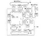
図1は、物理的に接続されており、かつ、伝送フレームで通信可能な全てのネットワークの構成を示す。この全てのネットワークの上には、オーディオネットワークシステム100を含む、4つのオーディオネットワークシステムが形成されている。各ネットワークシステムは、1又は複数のネットワークにより構成され、各ネットワークには、1又は複数のデバイスが接続される。図1では、システム100は、後述する「フルブリッジ」により相互に接続された4つのネットワーク1、50、51及び52(図1において点線で囲んだ範囲)で構成されており、他の3つのシステムx、y、zは、それぞれ、1つのネットワークで構成されている。そして、4つのオーディオネットワークシステムは、後述する「パーシャルブリッジ」により相互に接続される。図1では、1つの接続用ネットワークで、システム100とシステムxとが接続されており、もう一つの接続用ネットワークで、システム100とシステムyとシステムzとが接続されている。 FIG. 1 shows the configuration of all networks that are physically connected and that can communicate with each other in a transmission frame. Four audio network systems including the
図1のネットワーク1、50、51、52、53他は、それぞれ、カスケード状又はリング状に接続された複数のノード(装置)により構成される。図1に描かれた複数のブロックは各ネットワークを構成するノード(装置)であり、各ブロック間を結ぶ線Lはノード間の接続ケーブルを示す。1つのネットワークを構成する各ノード(装置)間には、複数チャンネルのオーディオ信号を含む伝送フレームの伝送経路が形成され、伝送経路を巡回する伝送フレームにより複数のノード間でオーディオ信号等のデータが送受信される。後述するように、ノードは、それぞれ、1又は2のネットワークに接続するための1又は2のインターフェースを有しており、その各インターフェースは、接続ケーブルを接続するための方向性を有する2つの端子を有する。一つは上流側のノードに接続するための上流側端子であり、もう一つは下流側のノードに接続するための下流側端子である。図1中の各ネットワークには、上流から下流へ向かう方向への矢印が付加されている。 Each of the
図2は、図1のネットワークシステム100を構成する1つのネットワーク1の構成例を示す。このネットワーク1に接続された複数装置を、システム100の一部という意味で「サブシステム1」と呼ぶことにする。サブシステム1は、2台のコンソール(CS1,CS2)2,3と、2台の信号処理エンジン(DSP_A、DSP_B)4,5と、3台の入出力装置(IO1,IO2及びIO3)6、7及び8からなる。システム100は、コンソール(CS1、CS2)2、3による制御に基づいて、入出力装置(IO1〜IO8)6、7及び8から入力された複数のオーディオ信号を、信号処理エンジン4、5で信号処理(特性の制御やミキシングなど)して、その信号処理結果(出力信号)を、入出力装置(IO1〜IO8)6、7及び8から出力する動作を行う。なお、システム100に2つの信号処理エンジン(DSP_A、DSP_B)4,5が具備されているのは、ミラーリング動作を行うためであり、いずれも同じ信号処理を行うものの、一方(稼動系)からの出力信号のみが通常時に入出力装置(IO1〜IO8)から出力され、他方(待機系)からの出力信号は出力されない。稼動系に異常が生じて正常な出力信号が出力されなくなったとき、待機系からの出力信号が入出力装置から出力される。 FIG. 2 shows a configuration example of one
《コンソールの構成》
図3(a)は、コンソール2,3の電気的ハードウェア構成例を示す。コンソール2,3は、ユーザによる操作に基づいて、ミキシングシステム内の各装置の動作をリモート制御する制御装置であって、CPU(Central Processing Unit、中央処理装置)10、ROM(Read Only Memory)及びRAM(Random Access Memory、ランダムアクセスメモリ)からなるメモリ11、PCインターフェース(PC_I/O)12、オーディオインターフェース(A_I/O)13、2つのネットワークI/O(N_I/O)14及び15、パネル表示部(P表示部)16、パネル操作子(P操作子)17、電動フェーダ18を備え、各構成要素がCPUバス10Bを介して接続される。また、A_I/O13、及びN_I/O14,15はオーディオバス(信号ルーティング)19を介して接続される。<Console configuration>
FIG. 3A shows an example of the electrical hardware configuration of the
CPU10は、メモリ11に記憶された制御プログラムを実行して、コンソールの全体動作を制御する。メモリ11は、CPU10が実行するプログラムのロード領域やワーク領域に使用される。
また、メモリ11には、当該システム100の範囲(当該コンソールによるリモート制御の範囲)にある各装置の現在の動作パラメータと同じデータ構成の動作パラメータ(各装置のパラメータ)を記憶したカレントメモリの領域、及び、後述するデバイスリストを記憶する領域等が設けられている。なお、システムの稼働中は、コンソールのカレントメモリの各装置のパラメータは、従来から知られる技術により、リモート制御対象の各装置内のカレントメモリに記憶されている動作パラメータとの間で同期している(動的に一致している)。すなわち、コンソールでのユーザ操作に応じて、コンソールのカレントメモリに記憶されたある装置のパラメータの値が変更されると、その変更がネットワークを介してその装置に伝達され、その装置のカレントメモリに記憶された動作パラメータの値が同様にリモートで変更される。逆に、ある装置でのユーザ操作等に応じて、その装置のカレントメモリに記憶された動作パラメータの値が変更されると、その変更を示す制御データがネットワークを介してコンソールに伝達され、コンソールのカレントメモリに記憶されたその装置のパラメータが同様にリモートで変更される。The
Further, the memory 11 is an area of the current memory in which operation parameters (parameters of each device) having the same data configuration as the current operation parameters of each device in the range of the system 100 (range of remote control by the console) are stored. And an area for storing a device list which will be described later. During system operation, the parameters of each device in the console's current memory are synchronized with the operation parameters stored in the current memory in each device to be remotely controlled using a conventionally known technique. Yes (matches dynamically). That is, when the value of a parameter of a device stored in the console's current memory is changed in response to a user operation on the console, the change is transmitted to the device via the network and stored in the current memory of the device. The stored operating parameter values are similarly changed remotely. Conversely, when the value of an operation parameter stored in the current memory of a device is changed in response to a user operation on a device, control data indicating the change is transmitted to the console via the network, and the console The device parameters stored in the current memory are also remotely changed.
P表示部16、P操作子17及び電動フェーダ18は、当該コンソールの操作パネル上に設けられたユーザインタフェースである。P表示部16は、CPU10からバス10Bを介して与えられた表示制御信号に基づいて各種画面を表示し、また、画面に表示された情報に基づく命令をユーザから受け付ける。P操作子17は、操作パネル上に配置された操作子群である。電動フェーダ18は、フェーダ型の操作子であり、ユーザが操作できるとともに、CPU10から与えられる駆動制御信号に基づいて操作位置が自動制御される。CUP10は、P表示部16、P操作子17及び電動フェーダ18に対するユーザの操作に応じて、パラメータの値を調整する。本明細書において「パラメータの値を調整する」とは、コンソールのカレントメモリに記憶されている動作パラメータのうちの、当該操作された操作子に割り当てられている或る装置の或るパラメータの値を、当該操作に応じた値に変更し、その装置がコンソール自身でない場合は、その変更をネットワーク越しにその装置に通知して、その装置のカレントメモリに記憶されているパラメータの値を同様にリモートで変更することである。各装置が備えているハードウェア、すなわち、各種オーディオ信号処理ブロック(後述する、A_I/O、N_IO、DSP部)やPC_I/O等の動作は、その装置のカレントメモリに記憶されている動作パラメータに応じて制御される。また、各装置のユーザインタフェースには、その装置のカレントメモリに記憶された動作パラメータに応じた表示が行われる。 The
A_I/O13は、複数chのオーディオ信号を入出力するためのインターフェースであって、アナログオーディオ信号やデジタルオーディオ信号を外部機器から入力するための複数の入力ポート、アナログオーディオ信号やデジタルオーディオ信号を外部機器へ出力するための複数の出力ポートを含む。さらに、アナログデジタル変換(AD変換)、デジタルアナログ変換(DA変換)、及びデジタル変換(フォーマット変換)を行うための機構を含む。また、各入力ポートが外部からオーディオ信号を入力する際の音量レベルや、該オーディオ信号をオーディオバスへ出力するL伝送チャンネル、各出力ポートがオーディオバスからオーディオ信号を取り込むL伝送チャンネルや、該オーディオ信号を外部へ出力する際の音量レベル等は、当該装置(この場合はコンソール)のカレントメモリに記憶された各対応するパラメータにより制御される。 The A_I /
第1N_I/O14及び第2N_I/O15は、当該装置をオーディオネットワークに接続するインターフェースであり、オーディオネットワーク経由の伝送フレームの送受信、該伝送フレームからの必要なオーディオ信号(波形データ)及び制御データを含む各種データの読み出し、該伝送フレームに対する波形データ及び制御データを含む各種データの書き込み、オーディオバス19を介した波形データの送受信、及び、CPUバス10Bを介した制御データ等の送受信を行うために必要な機構を有する。また、各N_I/O14,15が、伝送フレームからオーディオ信号を読み出す際のN伝送チャンネルや、該読み出したオーディオ信号をオーディオバスへ出力するL伝送チャンネルや、オーディオバスからオーディオ信号を取り込む際のL伝送チャンネルや、該取り込んだオーディオ信号を伝送フレームに書き込む際のN伝送チャンネル等は、当該装置(この場合はコンソール)のカレントメモリに記憶された各対応するパラメータにより制御される。 The first N_I /
第1N_I/O14及び第2N_I/O15は、それぞれ、オーディオネットワーク用の接続ケーブルを接続する上流側と下流側の2つの端子を有している。それぞれの端子は、図3において互いに逆向き1対の矢印により示すように、当該端子に接続された1つの装置との間で伝送フレームを双方向で送受信できるよう構成されている。第1N_I/O14及び第2N_I/O15を介した装置の接続及びネットワークの接続の詳細は後述する。 Each of the first N_I /
オーディオバス19は、A_I/O13及び2つのN_I/O14、15の間で、複数チャンネルのデジタルオーディオ信号(波形データ)を、サンプリング周期毎に、1サンプルずつ時分割伝送するローカルバスである。なお、A_I/O13及び2つのN_I/O14、15は、ワードクロックを用いた周知の技術により、波形データを処理するタイミングを同期する。すなわち、A_I/O13及び2つのN_I/O14、15のいずれか1つがワードクロックマスタに設定され、該ワードクロックマスタ以外がワードクロックスレーブに設定される。ワードクロックマスタがワードクロックを発生し、ワードクロックスレーブは、ワードクロックマスタにより発生されたワードクロックに同期したタイミングでワードクロックを生成し、生成されたワードクロックに基づくサンプリング周期のタイミングで波形データを処理する。 The
また、コンソール2,3は、PC_I/O12を介してパーソナルコンピュータ(PC)を外部接続できる。PC_I/O12を介してコンソール2又は3に接続されたPCは、ネットワーク1の各装置の動作をリモート制御するための制御装置として使用できる。なお、PCは、CPU、ROM、RAM、ディスプレイ、マウス操作子及びキーボード等を具備する汎用コンピュータである。 The
《エンジンの構成》
図3(b)はエンジン4,5の構成例を示しており、1つのエンジンは、CPU20、メモリ(ROM及びRAM)21、PC_I/O22、A_I/O23、2つのN_IO24及び25、信号処理部(DSP部)26、及び簡易ユーザインタフェース(簡易UI)27を含み、各部がCPUバス20Bを介して接続される。また、A_I/O23、N_I/O24、及びDSP部2がオーディオバス(信号ルーティング)28を介して接続される。CPU20は、メモリ(ROM及びRAM)21に記憶された制御プログラムを実行して、エンジン4,5の全体動作を制御する。エンジン4,5のメモリ21には、先述した動作パラメータを記憶するカレントメモリの領域やデバイスリストを記憶する領域の他に、DSP部26のマイクロプログラム等、当該エンジンの動作に必要な各種データを記憶する。また、簡易UI27は、電源スイッチや。また、メモリ21には、後述するデバイスリストを記憶する領域が設けられている。また、簡易UI27は、電源スイッチや動作チェック用のLEDインジケータなどである。<Engine configuration>
FIG. 3B shows a configuration example of the
DSP部26は、CPU20の指示に基づいて、各種のマイクロプログラムを実行し、オーディオ信号に対して各種のデジタル信号処理を施す。すなわち、当該装置(この場合はエンジン)のカレントメモリに記憶された対応するパラメータの値に基づいて、DSP部26は、オーディオバスの指定されたL伝送チャンネルからオーディオ信号を取り込み、該取り込んだオーディオ信号に対してデジタル信号処理を施し、処理済のオーディオ信号をオーディオバスの指定されたL伝送チャンネルへ出力する。DSP部26が実行する信号処理は、ミキシング処理、効果付与処理及び音量レベル制御処理等である。DSP部26の信号処理結果(出力信号)は、オーディオバス28を介しA_I/O23及びN_I/O24,25へ送信される。DSP部26は、1つのDSP(Digital Signal Processor)で構成してもよいし、バスで相互接続された複数のDSPで構成し、複数のDSPで信号処理を分散処理するようにしてもよい。 The
また、A_I/O23、N_I/O24,25、及びオーディオバス28は、図3(a)の対応する構成要素と同様に構成される。また、PC_I/O22を介してエンジン4,5にPCを接続できる。図2のサブシステム1では、エンジン4(DSP_A)にPC110が接続されている。 Further, the A_I /
《入出力装置の構成》
図3(c)は入出力装置6,7,8の構成例を示す。入出力装置は、CPU30、メモリ(ROM及びRAM)31、PC_I/O32、A_I/O33、第1N_I/O34、第2N_I/O35、及び、簡易ユーザインタフェース(簡易UI)36を備え、各部がCPUバス30Bを介して接続される。また、A_I/O33、第1N_I/O34、及び第2N_I/O35がオーディオバス(信号ルーティング)37を介して接続される。CPU20、及びメモリ(ROM及びRAM)21は、入出力装置の全体動作を制御する制御部である。また、メモリ21には、先述した動作パラメータを記憶するカレントメモリの領域やデバイスリストを記憶する領域が設けられている。簡易UI25は、簡易な表示器と幾つかの操作子群である。<Configuration of input / output device>
FIG. 3C shows a configuration example of the input /
A_I/O33、2つのネットワークI/O(第1N_I/O34及び第2N_I/O35)及び信号ルーティング28は、図3(a)の対応する構成要素と同様に構成される。入出力装置6,7,8は、オーディオ信号の入出力機能を担う装置であり、A_I/O33として多数のオーディオ信号入出力ポートを有している。また、PC_I/O32を介して各入出力装置6,7,8にPCを接続できる。 The A_I /
《装置間の接続》
各装置2〜8は、それぞれ、1つのN_I/O(14,15,24,25,34及び35)が有する上流側の端子に接続された接続ケーブルにより、当該装置の上流側の1つの装置に対して接続でき、また、下流側の端子に接続された接続ケーブルにより、当該装置の下流側の1つの装置に対して接続できる。例えば、図2において、CS1は、上流側のCS2と下流側のIO1とに接続されている。7つの装置2〜8の互いに隣接するもの同士が順次接続ケーブルで連結されることで、7つの装置2〜8をカスケード状又はリング状に接続してなる1つのネットワーク(サブシステム1)が形成される。<Connection between devices>
Each of the
図2において、装置2〜8を、エンジン4(DSP_A)と入出力装置8(IO3)を端部とする、1本のラインのような形態で、物理的に接続するカスケード状の接続形態が、実線で示されている。隣り合う2つの装置間を接続する接続ケーブルは、例えば、図4に例示するように、1本で伝送フレームを双方向通信できる構成とする。この場合、カスケード接続の端部以外の各装置は、あるN_I/Oの一方の端子で受信した伝送フレームを内部で折り返さず同じN_I/Oの他方の端子から送信するよう動作(ストレート転送)し、また、端部の各装置は、あるN_I/Oの一方の端子で受信した伝送フレームを内部で折り返して同じN_I/Oの同じ端子から送信するよう動作(折り返し転送)するので、装置2〜8の隣り合う各2つの装置間を1本の接続ケーブルでカスケード接続するだけで、伝送フレームTFが全ての装置2〜8の間を巡回するリング状の伝送経路TRを、形成できる。1つのネットワーク(ここではネットワーク1)において、カスケー又はリングネットワーク状に連結された複数の装置2〜8を巡るリング状伝送経路TRを形成する構造が経路形成部である。この伝送経路TRが形成された状態を、「カスケード」と呼ぶことにする。なお、図2において伝送経路TRの矢印は伝送フレームTFの流れる方向を示している。図2において、各装置は、装置を通過する伝送フレームの伝送経路TRの上側において、伝送フレームからの各種データの読み出し、又は、伝送フレームへの各種データの書き込みを行う。すなわち、前記カスケードの端部以外の各装置は、伝送フレームが上流側から下流側へ通過するときに、伝送フレームへのデータの読み書きを行い、前記端部の各装置は、下流側へ送信するとき、又は、上流側から受信したときに、伝送フレームへのデータの読み書きを行う。 In FIG. 2, there is a cascade connection form in which the
また、カスケード両端のエンジン4(DSP_A)と入出力装置8(IO3)を接続ケーブルで結ぶことで、装置2〜8を、端部を有さない1つのリングのような形態で、物理的に接続できる。カスケードの両端の装置が接続されたとき、該両端の装置は、カスケードの端部の装置の動作(折り返し転送)を中止し、端部以外の装置と同じ動作(ストレート転送)を開始することにより、リング状に接続された複数の装置上には、図2において一点鎖線で示すように、伝送フレームを伝送するリング状の伝送経路TRが2重に形成される。この状態を、「ループ」と呼ぶことにする。ループにおいては、隣り合う各2つの装置間は、双方向通信可能な接続ケーブルを用いて接続されており、ループ内の各装置は、一方のN_I/Oで受信した伝送フレームを内部で折り返さず他方のN_I/Oから送信するよう動作(ストレート転送)している。この場合、リング状に接続された装置のうちの任意の2装置間の接続が切断されたとしても、その切断箇所の両側の装置が、それぞれ、カスケードの端部の装置の動作(折り返し転送)を開始することにより、上述した「カスケード」の形態に移行することができ、伝送フレームの巡回を維持しうるので、ネットワークの安全性及び信頼性が高まる。なお、リングにおける各装置は、伝送フレームへの各種データの読み書きを、伝送フレームがその装置を上流側から下流側へ通過するときに行うが、この動作は、カスケードにおける端部以外の装置と全く同様である。 Further, by connecting the engine 4 (DSP_A) and the input / output device 8 (IO3) at both ends of the cascade with a connection cable, the
《マスタノード》
1つのネットワーク(サブシステム1)内の複数の装置2〜8のうちいずれか1つ(図2では、「IO2」)が、そのネットワークの「マスタノード」となる。この構成が、装置2〜8の1つをマスタノードとして指定する指定部に相当する。マスタノードは、所定のサンプリング周波数の1サンプリング周期毎に伝送フレームTFを作成して、作成された伝送フレームTFをネットワーク上に送出する動作を行う。マスタノード以外の装置は全てスレーブノードとなり、それぞれ、伝送経路TRの上流から伝送フレームを受信しつつ、伝送経路TRの下流へ転送する転送処理を行う。すなわち、マスタノードが伝送経路TRにおける最上流のノードとなり、伝送経路TRを伝送フレームが巡回し、最終的には最下流のノード(図2では「IO3」)からマスタノードに伝送フレームが帰還する。《Master node》
Any one of a plurality of
また、マスタノードは、ネットワーク内の各装置2〜8において波形データを処理するサンプリング周期のタイミングを同期させるワードクロックのワードクロックマスタとなる。各スレーブノードは、1つの伝送フレームTFの受信を開始したタイミングに同期して、波形データを処理するサンプリング周期を規定する信号であるワードクロックを発生することで、波形データの処理タイミングを、マスタノードにおけるサンプリング周期(ワードクロック)のタイミングに同期させる。 The master node is a word clock master of a word clock that synchronizes the timing of the sampling period for processing the waveform data in each of the
《伝送フレームの構成》
図5(a)は、オーディオネットワークで伝送される伝送フレームの構成例を示す。伝送フレームは、イーサネット(登録商標)のフレーム形式に準拠しており、プリアンブル40、管理データCD記憶領域41、音声信号領域42、イーサネット(登録商標)データ領域43、ITP領域44、メータ領域45、NC領域46、及び、フレームチェックシークエンス(FCS)領域47からなる。なお、図5(a)において、図面左側がフレームの伝送方向の前方、すなわち、伝送フレームの先頭となる。<< Configuration of transmission frame >>
FIG. 5A shows a configuration example of a transmission frame transmitted in the audio network. The transmission frame conforms to the Ethernet (registered trademark) frame format, and includes a
プリアンブル40には、IEEE(Institute of Electrical and Electronic Engineers)802.3で規定されるプリアンブルとともに、SFD(Start Frame Delimiter)、宛先アドレス、送信元アドレス、或いは当該伝送フレームの長さ等を記憶する。CD記憶領域41は、当該伝送フレームに含まれるデータを管理するデータ(伝送フレームの番号やサンプル遅れ値など)を記憶する。音声信号領域42は、複数の伝送チャンネル(例えば256チャンネル)を有し、各伝送チャンネルに波形データを1サンプルずつ記憶する。 The
イーサネット(登録商標)データ領域43は、各装置がイーサネット(登録商標)形式のフレームデータを書き込む領域であって、例えば、制御装置(コンソール2,3又はPC)により書き込まれたリモート制御用の制御データや、各装置の接続状況や動作状況の情報等のデータを記憶する。なお、イーサネット(登録商標)データ領域43よりもサイズの大きいフレームデータを伝送する場合、周知の技術により、送信側は複数に分割しデータを複数の伝送フレームに分けて伝送し、受信側は複数の伝送フレームから取り出した複数のデータを所定の順番に結合し、分割前のフレームデータを復元する。伝送フレームを通じて制御装置から前記各装置に制御データを送信して、制御データに従って各装置を制御する構造が特許請求範囲の制御部である。ITP領域44は、隣接するノード間でのコマンド及びコマンドに対する応答の伝送に使用する。メータ領域45はレベル表示メータ用のデータを記憶する。NC領域46はネットワーク構成を示すデータを記憶する。FCS47は、IEEE802.3で規定されたフレームのエラーを検出するエラーチェックコードデータを記憶する。本ネットワークでは複数機器を巡回する伝送フレームによって、オーディオ信号と制御データとが伝達される。従って、1つのネットワークに注目すると、オーディオ信号が伝達される範囲と、制御データが伝達される範囲とが、相互に同じになる。オーディオ信号が届くのに、制御データが届かないという状況は起こり得ない。 The Ethernet (registered trademark)
1つの伝送フレームのサイズを、サンプリング周期やネットワークの通信速度(伝送帯域幅)等の条件に基づき適切に設定することで、伝送フレーム全体を、1サンプリング周期内で、伝送経路TR(ネットワーク内の全ての装置を通る経路)を一巡させることができる。 By appropriately setting the size of one transmission frame based on conditions such as the sampling period and the communication speed (transmission bandwidth) of the network, the entire transmission frame is transmitted within one sampling period within the transmission path TR (in the network). It is possible to make a round of a route through all devices.
《N伝送chに対する割り当て》
図5(b)は音声信号領域42の複数のN伝送chに対する装置A〜Eの割り当て例であり、(c)は装置A〜Eからなるネットワーク構成例である。(c)において、カスケード接続された装置A〜Eからなるネットワークが示されている。装置Dがマスタノードであり、カスケード接続の端部の装置Aと装置Eが伝送フレームの折り返し端部となるループバック(LB)に設定される。マスタノードDで作成された伝送フレームは下流側の装置Eへと送信され、D→E(LB)→D→C→B→A(LB)→B→C→Dという順番で全ての装置A〜Dを通過するリング状の伝送経路を巡回する。先述したように、各装置による伝送フレームへのデータの読み書きは伝送フレームがその装置を上流側から下流側へ通過するときに行われるので、この場合、D→E→A→B→Cの順で、該読み書きを実行することになる。<< Allocation for N transmission channels >>
FIG. 5B is an example of assignment of devices A to E to a plurality of N transmission channels in the
(b)において、アルファベット文字が記された各区画A〜Eは、そのアルファベット文字に対応する装置A〜Eに対して割り当てられたN伝送チャンネルを表している。ネットワーク内の各装置に対して、その装置で必要な数のN伝送chが割り当てられる。N伝送chの割り当て管理はマスタノードが行う。各装置に割り当てられた領域(各装置が確保したN伝送ch)は、その装置のみが排他的に波形データ書き込むチャンネルとして使用できる。いずれの装置にも割り当てられていないN伝送チャンネルは「空きチャンネル(空きch)」である。 In (b), the sections A to E in which alphabet letters are written represent N transmission channels assigned to the devices A to E corresponding to the alphabet letters. Each device in the network is assigned as many N transmission channels as the device needs. The master node performs assignment management of N transmission channels. The area allocated to each device (N transmission channels secured by each device) can be used exclusively as a channel for writing waveform data exclusively by that device. An N transmission channel that is not assigned to any device is an “empty channel (empty channel)”.
各装置A〜EのN_I/O(図3の符号14,15,24,34,35)は、伝送フレーム伝送方向の上流にある装置から伝送フレームを受信し、且つ、下流に転送する処理を行う過程で、その装置A〜Eに割り当てられたN伝送chに対する波形データ(オーディオ信号)の書き込み、及び、所望のN伝送chからの波形データ(オーディオ信号)の読み出しを行う。波形データを読み出す所望のN伝送chは、その波形データの送信元装置に割り当てられえたN伝送chである。サンプリング周期毎に伝送経路を1巡回する伝送フレームに対して波形データ等の読み出し及び書き込みを行うことで、ネットワークのいずれの装置から伝送フレームに書き込まれた波形データ等であっても、全ての装置が略リアルタイムで該波形データ等を受信することが可能である。なお、マスタノードDは、伝送経路を一巡した伝送フレームの終端まで受信してから、次の伝送フレームの作成及び送信を開始するのが好ましい。すなわち各装置A〜EのN_I/O(図3の符号14,15,24,34,35)による上記の動作がオーディオ信号経路制御部である。 N_I / O (
なお、ループバック端部となる装置A及びE以外の装置は、伝送フレームを往路と復路の2度通過させることになるが、波形データ等の読み出し及び及び書き込みを行うのは、伝送フレームをその装置を上流側から下流側へ通過させるときの1度のみである。
なお、ネットワーク1に適用するオーディオネットワーク経由の伝送フレームの伝送方式は、例えば特許文献「特開2008‐99264号公報」に開示された技術により行うことができる。当該文献に開示された伝送フレームのサイズやネットワークの仕様等の各種技術的事項は本実施例にも適用可能である。The devices other than the devices A and E that are the loopback end portions pass the transmission frame twice in the forward path and the return path. However, reading and writing of the waveform data and the like are performed in the transmission frame. Only once when passing the device from the upstream side to the downstream side.
Note that the transmission method of the transmission frame via the audio network applied to the
《ネットワーク同士の接続》
サブシステム1内の各装置2〜8は、上述のように、それぞれ、2つのネットワークI/O(第1N_I/O14,24,34、及び第2N_I/O15,25,35)を有している。これら2つのN_I/Oのうち、一方の第1N_I/O14,24,34は、当該装置を、一方のネットワーク内の他装置に接続するために使用され、他方の第2N_I/O15,25,35は、該一方のネットワークに対して、他方のネットワークを接続するために使用される。<Connection between networks>
As described above, each of the
2つのN_I/Oを介して、2つのネットワークを接続した装置は、接続ノード(ブリッジ装置)として動作をする。ユーザは、ブリッジ装置に対して、接続ノードの動作として、当該接続された一方のネットワークを他方のネットワークの拡張として結合する「フルブリッジ」モード、又は、それぞれ別の独立したネットワークとして結合する「パーシャルブリッジ」モードの何れかを設定できる。図1の例では、ネットワーク1中のコンソール2(CS1)及びコンソール3(CS2)がそれぞれ、「フルブリッジ」に設定され、入出力装置6(IO1)及び、入出力装置8(IO3)がそれぞれ、「パーシャルブリッジ」に設定される。なお、ブリッジ装置にかかる設定操作は、例えば個々の接続ノード(ブリッジ装置)が有するユーザインタフェース(P表示部16、P操作子17、簡易UI27,36)、或いは、オーディオネットワークシステム100中のいずれかの制御装置のユーザインタフェースを用いて行われ、ブリッジ装置は、該設定操作に応じて、制御装置および当該接続ノードの各カレントメモリに記憶された当該接続ノードの2つのN_I/Oのパラメータを設定する。また、ブリッジ設定は、個々の接続ノード(ブリッジ装置)のCPUがユーザの指示に応じて、自身の設定に関する制御を行っても良いし、或いは、制御装置又はマスタノードにより各接続ノードにけるブリッジ設定をリモート制御してもよい。 A device that connects two networks via two N_I / Os operates as a connection node (bridge device). The user can connect to the bridge device as the operation of the connection node in the “full bridge” mode in which one of the connected networks is combined as an extension of the other network, or “partial” in which each network is combined as another independent network. Either “Bridge” mode can be set. In the example of FIG. 1, the console 2 (CS1) and the console 3 (CS2) in the
接続ノードは、当該接続ノードにより接続された2つのネットワークにおけるサンプリング周波数が一致するとき(言い換えれば、当該接続ノードが2つのネットワークの少なくとも一方におけるマスタノードに設定されているとき)、「フルブリッジ」又は「パーシャルブリッジ」に応じた動作態様で、2つのネットワーク間でオーディオ信号を「橋渡し」する機能を実行する。オーディオ信号の「橋渡し」の動作とは、接続ノードを介して2つのネットワーク間でオーディオ信号を送受信することである。 A connection node is “full bridge” when the sampling frequencies in the two networks connected by the connection node match (in other words, when the connection node is set as a master node in at least one of the two networks). Alternatively, a function of “bridging” an audio signal between two networks is executed in an operation mode corresponding to “partial bridge”. The operation of “bridging” an audio signal means transmitting and receiving an audio signal between two networks via a connection node.
《フルブリッジ》
フルブリッジ設定により2つのネットワークを接続する場合、各ネットワークを流れる各伝送フレームの音声信号領域42には、それぞれ、両ネットワーク内の各装置に対して、その装置で必要な数のN伝送chが割り当てられる。つまり、両ネットワークでは伝送フレームの伝送速度もN伝送ch数も共通しており、それぞれ共通の伝送フレームの音声信号領域42に対するN伝送ch割り当てを行う。なお、両ネットワークにおけるN伝送chの割り当ては、フルブリッジで接続された2つのネットワーク内のいずれか1つのマスタノードが行うものとする。
接続ノードは、第1N_I/O(14,24,34)を介して一方のネットワークを流れる伝送フレームから、当該一方のネットワーク内の何れかの装置に割り当てられた全てのN伝送chから波形データを読み出して、読み出された全ての波形データを、それぞれ、第2N_I/O(15、25、35)を介して他方のネットワークを流れる伝送フレームの同じN伝送chに書き込む。また、第2N_I/Oを介して、該他方のネットワーク内の何れかの装置に割り当てられた全てのN伝送chから波形データを読み出して、読み出された全ての波形データを、それぞれ、第1N_I/Oを介して該一方のネットワークを流れる伝送フレームの同じN伝送chに書き込む。これにより、伝送フレームの音声信号領域42に記載 されるオーディオ信号は、一方のネットワークと他方のネットワークとで全く同じとなるが、オーディオ信号の観点で見ると、1つの伝送フレームが2つのネットワークを巡回しているのと全く等価である。《Full Bridge》
When two networks are connected by a full bridge setting, the
The connection node receives waveform data from all N transmission channels assigned to any device in the one network from the transmission frame flowing in one network via the first N_I / O (14, 24, 34). Read and write all the read waveform data to the same N transmission channel of the transmission frame flowing through the other network via the second N_I / O (15, 25, 35). Further, the waveform data is read out from all N transmission channels assigned to any device in the other network via the second N_I / O, and all the read waveform data are respectively converted into the first N_I. Write to the same N transmission channels of transmission frames flowing through the one network via / O. As a result, the audio signal described in the
すなわち、フルブリッジ設定の場合、2つのネットワークの各装置は、他方のネットワークのいずれの装置に対しても、自身が属するネットワーク内の各装置と同様に、N伝送ch毎のオーディオ信号の送受信を行うことができる。従って、フルブリッジで接続された2つのネットワークは、他方のネットワークの資源を当該ネットワーク内の資源と同等に利用し、該2つのネットワークで全体として1つの信号処理を行うネットワークシステムとして動作できる。つまり、1つのネットワークに対して他のネットワークを、当該ネットワークの拡張として結合することになる。 That is, in the case of the full bridge setting, each device in the two networks transmits / receives an audio signal for each of the N transmission channels to any device in the other network, like each device in the network to which the device belongs. It can be carried out. Therefore, two networks connected by a full bridge can operate as a network system that uses the resources of the other network as much as the resources in the network and performs one signal processing as a whole in the two networks. That is, one network is combined with another network as an extension of the network.
《パーシャルブリッジ》
パーシャルブリッジ設定で2つのネットワークを接続する場合、各ネットワークを流れる各伝送フレームの音声信号領域42のN伝送chに対する装置の割り当ては、図5(a)の説明と同様に、当該ネットワーク内の装置に対してのみ行われる。従って、この場合、2つのネットワークの伝送フレームの伝送速度もN伝送ch数も異なり、伝送フレームの音声信号領域42のN伝送ch割り当ては、ネットワーク毎に異なる。
パーシャルブリッジに設定された接続ノードは、第1N_I/O(14,24,34)を介して一方のネットワークを流れる伝送フレームから、当該システム内の各装置が書き込んだN伝送チャンネルのうちのブリッジするよう設定されたN伝送チャンネルの波形データをそれぞれ読み出し、これら読み出した波形データを、第2N_I/O(15、25、35)を介して他方のネットワーク(接続用ネットワーク)を流れる伝送フレームにおける、当該接続ノードに対して割り当てられたN伝送chに書き込む。また、また、第2N_I/Oを介して、接続用ネットワーク を流れる伝送フレームから、該接続用ネットワークに接続された何れかの他システムの接続ノードに割り当てられたN伝送チャンネルのうちのブリッジするよう設定されたN伝送チャンネルの波形データをそれぞれ読み出し、これら読み出した波形データを、第1N_I/Oを介して当該接続ノードに対して割り当てられたN伝送chに書き込むことも可能である。《Partial Bridge》
When two networks are connected in the partial bridge setting, the device allocation to the N transmission channels of the
A connection node set as a partial bridge bridges N transmission channels written by each device in the system from a transmission frame flowing through one network via the first N_I / O (14, 24, 34). The waveform data of the N transmission channels set as described above are read out, and these read out waveform data in the transmission frame flowing through the other network (connection network) via the second N_I / O (15, 25, 35) Write to the N transmission channels assigned to the connection node. In addition, a bridge of N transmission channels assigned to a connection node of any other system connected to the connection network is bridged from the transmission frame flowing through the connection network via the second N_I / O. It is also possible to read the waveform data of the set N transmission channels and write these read waveform data to the N transmission channels assigned to the connection node via the first N_I / O.
従って、パーシャルブリッジ設定の場合、1つの接続用ネットワークに接続された一方のシステムの各装置は、同接続用ネットワークに接続された他方のシステムのオーディオ信号のうち、該他方のシステムの接続ノードにおいてブリッジするよう設定されているオーディオ信号を、該一方のシステムの接続ノードでブリッジ設定して受け取ることはできるが、該他方のシステムの接続ノードでブリッジするよう設定されていないオーディオ信号は、どうやっても受け取ることができない。パーシャルブリッジ設定は、あるシステムの接続ノードを、システムとシステムとを物理的に接続するための接続用ネットワークに接続するものであり、各システムは、1つの独立したオーディオ信号処理システム(個別のシステム)として動作する。 Therefore, in the case of the partial bridge setting, each device of one system connected to one connection network is connected to a connection node of the other system among audio signals of the other system connected to the connection network. Audio signals that are set to be bridged can be received by being bridged at the connection node of the one system, but audio signals that are not set to be bridged at the connection node of the other system are received anyway. I can't receive it. In the partial bridge setting, a connection node of a system is connected to a connection network for physically connecting the systems, and each system has one independent audio signal processing system (individual system). ).
図1の接続例では、サブシステム1に対して、フルブリッジ設定によりネットワーク50とネットワーク51が接続され、さらに、ネットワーク50に対してフルブリッジ設定でネットワーク52が接続される。この場合、サブシステム1及びネットワーク50〜52(図1において点線で囲う範囲)が、全体として1つの信号処理を行うオーディオネットワークシステム100として動作する。システム100内の制御装置(CS1、CS2、PC110、又は、PC111)は、システム100内の全ての装置のリモート制御に必要なデータをカレントメモリに記憶し、自身が属するネットワーク内の各装置と同様に、システム100内の他のネットワークに属する各装置をリモート制御できる。 In the connection example of FIG. 1, the
他方、サブシステム1に対して、パーシャルブリッジ設定で他システムx及びyが接続され、さらに、他システムyに対して他システムzが接続されるが、これら他システムx、y及びzは、サブシステム1とは独立したオーディオ信号処理システムとして動作する。ネットワークシステム100内の制御装置は、他システムx、y及びzにのみ属する装置をリモート制御しない。
図1の構成のネットワークでは、同じオーディオ信号を運んでいる伝送フレームがどの範囲を巡回しているのか、言い換えれば、同じオーディオ信号を共有するオーディオネットワークシステム1がどの範囲なのかを、以下の観点においてユーザが確認する必要がある。
i)1つのネットワークの伝送フレームの伝送経路が具体的にどの装置を巡回しているか。つまり、物理的・電気的に接続された複数の装置において、1つのネットワークの伝送フレームの伝送経路は、各機器の設定や状況に応じて変化するので、複数の装置が物理的、電気的に接続されていたとしても、その全てがその伝送経路に入っているとは限らない。
ii)物理的・電気的にリング状に接続された複数の装置において、1つのネットワークの伝送フレームがリング状に巡回しているか、それともカスケード状に巡回しているか。つまり、物理的・電気的にリング状に接続された複数の装置において、1つのネットワークの伝送フレームは、そのリング状の接続に沿った伝送経路を巡回しているとは必ずしも限らない。伝送フレームが、リング状の接続ではなく、カスケード状の接続に沿って巡回している場合、リダンダンシ動作による保護は有効とならない。
iii)物理的に1つの装置の2つのN_I/Oに、それぞれ1又は複数の装置が接続されている場合に、その1つの装置が接続ノード(ブリッジ)として動作しているか否か。つまり、物理的に1つの装置の2つのN_I/Oに、それぞれ1又は複数の装置が接続されている場合に、その1つの装置が接続ノード(ブリッジ)として動作しているとは限らない。何れか一方又は両方のN_I/Oが、伝送フレームの巡回経路に入っていない可能性がある。
iv)さらに、接続ノード(ブリッジ)として動作している装置は、フルブリッジにて接続しているかそれともパーシャルブリッジとして接続しているか。つまり、接続ノード(ブリッジ)により2つのネットワークが接続されている場合に、その接続ノードが1つのネットワークの拡張として2つのネットワークを接続している(フルブリッジ)とは限らず、それぞれ独立したネットワークとして2つのネットワークを接続している(パーシャルブリッジ)可能性がある。
これらをユーザが容易に確認できるようにするため、このオーディオネットワークシステム100では、各制御装置(コンソール2、3、PC110、111)の表示器に「オーディオネットワークビュー画面」を表示できるようになっている。On the other hand, the other systems x and y are connected to the
In the network having the configuration shown in FIG. 1, the range of the transmission frames carrying the same audio signal circulates, in other words, the range of the
i) Which device is specifically traveling around the transmission path of a transmission frame of one network. In other words, in a plurality of physically and electrically connected devices, the transmission path of a transmission frame of one network changes depending on the setting and situation of each device, so that the plurality of devices are physically and electrically connected. Even if they are connected, not all of them are in the transmission path.
ii) Whether a transmission frame of one network circulates in a ring shape or circulates in a cascade manner in a plurality of devices physically and electrically connected in a ring shape. That is, in a plurality of devices physically and electrically connected in a ring shape, a transmission frame of one network does not always circulate through a transmission path along the ring connection. If the transmission frame circulates along a cascade connection instead of a ring connection, the protection by the redundancy operation is not effective.
iii) Whether one device is operating as a connection node (bridge) when one or more devices are connected to two N_I / Os of one device physically. In other words, when one or a plurality of devices are connected to two N_I / Os of one device physically, the one device does not necessarily operate as a connection node (bridge). Either one or both N_I / Os may not be in the cyclic path of the transmission frame.
iv) Furthermore, is the device operating as a connection node (bridge) connected as a full bridge or as a partial bridge? In other words, when two networks are connected by a connection node (bridge), the connection node is not necessarily connected to two networks as an extension of one network (full bridge), and each network is independent. There is a possibility that two networks are connected (partial bridge).
In order to allow the user to easily confirm these, the
《オーディオネットワークビュー画面》
図6は、システム100の接続状態をグラフィック表示する「オーディオネットワークビュー画面」の構成例であり、サブシステム1内のエンジン4(「DSP_A」)に接続されたPC110のディスプレイに表示された「オーディオネットワークビュー画面」を示している。PC110のディスプレイ又はコンソール2,3のP表示部16にオーディオネットワークビュー画面を表示する構成が、特許請求範囲の表示部に相当する。<Audio network view screen>
FIG. 6 is a configuration example of an “audio network view screen” that graphically displays the connection status of the
ネットワーク表示領域60は、システム100を構成する複数のネットワークのそれぞれに対応する複数の表示段61a〜61fからなる。複数の表示段61a〜61fは、画面上下方向に1段ずつ並べられている。なお、図6において、各表示段61a〜61fの段毎の区切りを1点鎖線で示した。 The
最上段61aは、基本ネットワークを構成する各装置を表す複数の装置画像62を、当該ネットワークにおける装置の接続順に従って、画面横方向に並べて表示する。基本ネットワークはオーディオネットワークビュー画面の最上段61aに表示されるネットワークであり、典型的には当該オーディオネットワークビュー画面を表示している装置が属するネットワークである。 The uppermost 61a displays a plurality of
2段目以降の表示段61b〜61fは、当該表示段よりも上段に表示されたネットワーク中の接続ノードに接続されたネットワークを表示する。前記接続ノードがフルブリッジに設定されている場合、表示段には、その接続ノードにより接続されたネットワークを構成する各装置を表す装置画像62が、当該ネットワークにおける装置の接続順に従って、画面横方向に並べて表示される。すなわち、この表示を行うためには、その接続ノードによって接続されたネットワークの伝送フレームの伝送経路上の全ての装置の接続を検出しておく必要がある。また、前記接続ノードがパーシャルブリッジに設定されている場合、表示段には、パーシャルブリッジ画像67が表示される。この表示には、その接続ノードによって接続されたネットワークにおいて、その接続ノードに隣接している装置の情報があれば充分であり、該ネットワーク上のその他の装置の情報は必要ない。 The second and subsequent display stages 61b to 61f display the networks connected to the connection nodes in the network displayed above the display stage. When the connection node is set to a full bridge, a
1つの装置画像62には、装置を特定する情報(装置名)63と、当該装置が有する2つのネットワークI/Oの構成を示す画像64,65が含まれる。N_I/O画像64,65上の数字(1又は2)は、第1N_I/O及び第2N_I/Oの区別を示す。また、各N_I/O画像64,65には2つの端子を示す2つの丸印が描かれており、端子を示す2つの丸印の間に示された矢印により、それらのうちの左側の端子が上流であり、右側の端子が下流であることが示されている。 One
2つの装置画像62を結ぶ線66は、当該2つの装置画像62に対応する装置間の接続ケーブルを示す画像である。接続ケーブル画像66は、2つの装置画像62のN_I/O画像64,65の端子間を結ぶよう描かれている。よって、接続ケーブル画像66が接続されたN_I/O画像64,65の端子の向き(上流側か下流側か)からも装置の接続順を識別可能である。このネットワークビュー画面では、各装置の左側の端子を上流側、右側の端子を下流側とするとともに、各ネットワークに接続された複数の装置を、一番左が最上流となり、右に従って下流となるように並べている が、これら全てを反転して、各装置の左側の端子を下流側、右側の端子を上流側とするとともに、各ネットワークに接続された複数の装置を、一番左が最下流となり、右に従って上流となるように並べるようにしてもよい。 A
また、ネットワーク表示領域60の左側には、各表示段61b〜61fに対応して、その表示段に対応するネットワークを示す番号PN1〜PN6とプロパティ表示ボタン(「Prop」)67が表示される。各プロパティ表示ボタン68を押すことで、ボタンに対応する番号PN1〜PN6のネットワークのプロパティを画面に表示させることができる。 Also, on the left side of the
《デバイスリスト》
オーディオネットワークビュー画面の内容は、デバイスリストに基づいて描画される。デバイスリストは、各装置のN_I/Oによるオーディオネットワーク通信機能(詳しくはオーディオネットワーク通信プロトコルの階層モデルにおけるMAC層)により作成されるもので、各装置のメモリ11,21,31には、その装置が属するネットワークに対して接続された全てのネットワーク(図1の場合は8ネットワーク)について、各ネットワーク毎の、伝送フレームの伝送経路上の全ての装置の情報を記載した「デバイスリスト」が記憶される。かかるデバイスリストを作成・記憶する構成が、1つのネットワーク(基本ネットワーク)の前記リング状伝送経路上にある複数の装置と、該複数の装置が前記ケーブルによって連結されている接続順とを検出する第1検出部、別のネットワーク(基本ネットワークに直接又は間接的に接続されたネットワーク)の前記リング状伝送経路上にある複数の装置を検出し、且つ、該複数の装置が前記ケーブルによって連結されている接続順を検出する第2検出部である。なお、前記オーディオネットワークシステム100は、基本ネットワークと、フルブリッジに設定された1又は複数の接続ノードによって、基本ネットワークに直接又は間接的に接続された全てのネットワークとによって構成される。すなわち、ネットワークビュー画面上の表示のうち、当該ネットワークシステム100を構成するネットワークの表示は、当該ネットワークシステム100に含まれる全てのネットワークのデバイスリストがあれば、実行可能である。一方、接続ネットワークに関するパーシャルブリッジ画像67は、当該ネットワークシステム100に含まれるパーシャルブリッジに設定された接続ノードに、当該接続ネットワーク上で隣接する装置の情報とがあれば表示できる。従って、前記「接続された全てのネットワーク(図1)」の各ネットワーク毎のデバイスリストを記憶する代わりに、当該ネットワークシステム100に含まれる全てのネットワークのデバイスリスト(最低限のデバイスリスト)だけを作成するようにしてもよい。さらに、パーシャルブリッジ画像67の表示を行うためには、当該ネットワークシステム100に含まれる前記パーシャルブリッジに設定された接続ノードから、前記接続ネットワークにおける隣接装置の情報を入手すればよい。或いは、前記最低限のデバイスリストに加えて、前記パーシャルブリッジに設定された接続ノードに直接接続された接続ネットワーク(隣接ネットワーク)のデバイスリストを作成するようにしてもよい。<Device list>
The contents of the audio network view screen are drawn based on the device list. The device list is created by an audio network communication function based on N_I / O of each device (specifically, the MAC layer in the hierarchical model of the audio network communication protocol). For all networks connected to the network to which the network belongs (8 networks in the case of FIG. 1), a “device list” that stores information on all devices on the transmission path of the transmission frame for each network is stored. The A configuration for creating and storing such a device list detects a plurality of devices on the ring-shaped transmission path of one network (basic network) and a connection order in which the plurality of devices are connected by the cable. A first detection unit that detects a plurality of devices on the ring-shaped transmission path of another network (a network directly or indirectly connected to a basic network), and the plurality of devices are connected by the cable; It is the 2nd detection part which detects the connection order which is. The
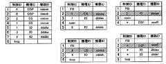
図7は、デバイスリストの構成例であり、ネットワーク1内のエンジン4(「DSP_A」)のメモリ21に記憶された複数のデバイスリスト(ネットワーク1、ネットワーク50、ネットワーク51、他システムx、及び、IO3とDSPxからなるネットワーク53に関する各デバイスリスト)が例示されている。なお、システム100中の何れかの装置に接続されたPCは、接続された装置のメモリ11,21,31からネットワーク毎の「デバイスリスト」を取得して、自身のメモリに記憶する。 FIG. 7 is a configuration example of a device list, and a plurality of device lists (
1つのデバイスリストは、1つのネットワークにおける伝送フレームの伝送経路上の1又は複数の装置を特定する情報として、装置毎に、制御ID、機種ID、及び機器IDを記憶する。制御IDは、制御装置が当該装置を識別するための制御装置によるリモート制御用のID番号である。機種IDは、装置の機種を識別する情報であって、機種毎に異なる。図7では「DSP」が信号処理エンジン、「CS」がコンソール、「IO」が入出力装置をそれぞれ示す。機器IDは、各装置の機器(個体)をユニークに識別する情報である。1つのデバイスリストに記録された制御ID、機種ID及び機器IDに基づいて、1つのネットワークを構成する装置を特定できる。なお、デバイスリストはオーディオネットワークで接続された装置を記録したものであるが、装置に対してPC_I/O12、22、32を介して接続されたPCは、その接続された装置の一部と看做され、デバイスリストには記録されない。 One device list stores a control ID, a model ID, and a device ID for each device as information for specifying one or more devices on a transmission path of a transmission frame in one network. The control ID is an ID number for remote control by the control device for the control device to identify the device. The model ID is information for identifying the model of the apparatus and is different for each model. In FIG. 7, “DSP” indicates a signal processing engine, “CS” indicates a console, and “IO” indicates an input / output device. The device ID is information that uniquely identifies a device (individual) of each device. Based on the control ID, model ID, and device ID recorded in one device list, devices constituting one network can be specified. The device list records devices connected via the audio network, but the PC connected to the device via the PC_I /
また、デバイスリストにおいて、各装置を特定する情報(制御ID、機種ID、及び機器ID)は、当該ネットワークの伝送フレームの伝送経路における装置の物理的な接続順にリストに記録される。各情報が記録された行の左端の番号は接続順に対する番号となる。各情報の記録順に基づいて、1つのネットワークを構成する装置の接続順を特定できる。 In the device list, information (control ID, model ID, and device ID) for identifying each device is recorded in the list in the physical connection order of the devices in the transmission path of the transmission frame of the network. The number at the left end of the line in which each information is recorded is the number for the connection order. Based on the recording order of each information, the connection order of the devices constituting one network can be specified.
デバイスリストに記録される装置の接続順は、当該デバイスリストを記憶している装置を起点とする順番である。例えば、図7はDSP_Aに記憶されたデバイスリストを例示しているので、ネットワーク1のデバイスリストの先頭にはDSP_Aに対応する情報が記録される。また、他のネットワークのデバイスリストにおいては、そのネットワークとネットワーク1を接続する接続ノードが先頭になる。図7において、ネットワーク1に対して接続された他のネットワークのデバイスリストにおいて、接続ノードに対応する行をハッチングで示した。 The connection order of devices recorded in the device list is an order starting from the device storing the device list. For example, since FIG. 7 illustrates the device list stored in DSP_A, information corresponding to DSP_A is recorded at the top of the
また、データリストには、装置間の接続状態を示す情報として、リスト末尾(接続順末尾)に記載された機器IDに対応する装置からリスト先頭(接続順先頭)に記載された機器IDに対応する装置への接続を示すループ(loop)記号と、リストのある接続順の制御ID機器IDに対応する装置とその次の接続順の機器IDに対応する装置との隣接する2つの装置間の接続が切れていることを示す(open)記号との何れかが記録される。ここで、リスト末尾の次の接続順は、リスト先頭に戻るものとする。図7において、装置間の接続状態を示す情報は制御ID欄に記録されており、例えば、ネットワーク1のデバイスリストの行番号「8」の制御ID欄にループを示す情報「loop」が記録される。また、ネットワーク50のデバイスリストの行番号「4」の制御ID欄にループを示す情報「loop」が記録される。なお、デバイスがリング状に接続されたネットワークについて、デバイスリストの“loop”フラグは必須でなはい。例えば、「“open”が記載されていなければ、そのデバイスリストは“loop”と看做す」ことができる。 In the data list, as information indicating the connection state between devices, the device corresponding to the device ID described at the end of the list (end of connection order) corresponds to the device ID described at the top of the list (first of connection order). A loop symbol indicating a connection to a device to be connected, and a device corresponding to the control ID device ID in the connection order in the list and a device corresponding to the device ID in the next connection order between two adjacent devices Any of the (open) symbols indicating that the connection is broken is recorded. Here, it is assumed that the next connection order at the end of the list returns to the top of the list. In FIG. 7, information indicating the connection state between devices is recorded in the control ID column. For example, information “loop” indicating a loop is recorded in the control ID column of the line number “8” of the device list of the
ネットワーク1に接続された他のネットワークのデバイスリストにおいて、当該接続をする接続ノードを示す行(2行目)の1行上(1行目)の制御ID欄には、当該接続ノードのブリッジ設定を示す情報(フルブリッジモードを示す記号FB又はパーシャルブリッジモードを示す記号PB)が記録される。例えば、ネットワーク50のデバイスリストの行番号「1」の制御ID欄にはブリッジ設定情報として「FB」が記録される。また、ネットワーク53のデバイスリストの行番号「1」の制御ID欄にはブリッジ設定情報として「PB」が記録される。これにより、ネットワーク1に対する当該ネットワークの接続(当該接続ノードの設定)がフルブリッジ及びパーシャルブリッジのいずれであるかを特定できる。 In the device list of another network connected to the
なお、システム100の制御範囲にないネットワーク(パーシャルブリッジに設定された接続ノードにより、ネットワーク1に対して接続されたネットワーク53、他システムx、y、z)にのみ属する装置については、リモート制御しないので制御IDを無視できる。従って、それら装置の制御ID欄には値として"don't care"(例えば、ネットワーク53のリストにおける行番号「4」の「*」)が記録される。 Note that devices that belong only to networks that are not within the control range of the system 100 (the
システム100内のいずれかのネットワークに属する制御装置のCPU(コンソール2,3のCPU10、或いは、PC110,111のCPU)は、ユーザからオーディオネットワークビュー画面表示指示を受けたとき、当該制御装置のディスレイ(コンソール2,3のP表示部16、或いは、PC110,111のディスプレイ)に、デバイスリストに基づくオーディオネットワークビュー画面を表示する処理を行う。 When a CPU of the control device (
《オーディオネットワークビュー画面表示処理》
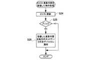
図8は、ユーザからオーディオネットワークビュー画面表示指示を受けたとき、制御装置のCPUが実行する処理を説明するフローチャートである。なお、一例としてDSP_Aに接続されたPC110にて表示指示が行われ、PC110のCPUが処理を実行することを想定する。<Audio network view screen display processing>
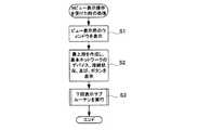
FIG. 8 is a flowchart for explaining processing executed by the CPU of the control device when receiving an audio network view screen display instruction from the user. As an example, it is assumed that a display instruction is given by the
ステップS1において、CPUは、ディスプレイに、オーディオネットワークビュー画面用のウインドウを表示する。ここで表示されるオーディオネットワークビュー画面用のウインドウにおいてネットワーク表示領域60には、表示段61a〜fや装置画像62を表示していない空の状態である。 In step S1, the CPU displays a window for an audio network view screen on the display. In the window for the audio network view screen displayed here, the
ステップS2において、CPUは、ネットワーク表示領域60の上端部分に最上段61aを作成し、メモリに記憶されたネットワーク1(基本ネットワーク)のデバイスリストに基づいて、作成された最上段61aに、当該基本ネットワークを構成する全ての装置を示す装置画像62を、その接続順に横方向で並べて表示し、且つ、それら装置画像62の間を結ぶ接続ケーブル画像66を表示する。なお、各装置画像62に表示する装置名63は、例えば機種IDと制御IDの組み合わせなど、装置を特定できる適宜の名称であってよい。また、最上段61aの作成に伴い、CPUは、作成された最上段61aの左側に、当該ネットワークのプロパティ表示ボタン68と当該ネットワークのネットワーク番号(PN1)を表示する。 In step S2, the CPU creates an
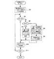
ステップS3において、CPUは図9に示す下段表示サブルーチンを実行する。図9のステップS4において、CPUは、処理対象となる表示段(現在段)に表示されたネットワーク中の1つ目の装置を処理対象に指定する。ここで、図8のステップS3により起動した下段表示サブルーチンにおいては、ステップS4における処理対象の表示段(現在段)は、最上段61aである。また、1つ目の処理対象に指定される装置は、例えば接続順で先頭の装置(当該表示段において左端の装置画像62に対応する装置)である。 In step S3, the CPU executes a lower display subroutine shown in FIG. In step S4 in FIG. 9, the CPU designates the first device in the network displayed on the display stage (current stage) to be processed as the processing target. Here, in the lower display subroutine started in step S3 of FIG. 8, the display stage (current stage) to be processed in step S4 is the
ステップS5において、CPUは、メモリに記憶されたデバイスリストに基づいて、処理対象に指定された装置が接続ノード(ブリッジ)か否かを判断する。処理対象に指定された装置が接続ノードの場合(ステップS5のYES)、CPUは、ステップS6において、メモリに記憶されたデバイスリストに基づいて、接続ノードがフルブリッジ及びパーシャルブリッジの何れに設定されているかを判断する。 In step S5, the CPU determines whether the device designated as the processing target is a connection node (bridge) based on the device list stored in the memory. If the device designated as the processing target is a connection node (YES in step S5), the CPU sets the connection node as a full bridge or a partial bridge in step S6 based on the device list stored in the memory. Judgment is made.
処理対象に指定された装置が接続ノードであり(ステップS5のYES)、且つ、パーシャルブリッジに設定されている場合(ステップS6の「partial」)、ステップS9において、CPUは、ネットワーク表示領域60に既に表示されている表示段の一番下に、新たな表示段を追加形成し、メモリに記憶されたデバイスリストに基づいて、該形成された表示段にパーシャルブリッジ画像67を表示し、且つ、前記指定された装置の装置画像62とパーシャルブリッジ画像67を結ぶ接続ケーブル画像66を表示する。また、CPUは、今回追加形成された表示段の左側に、当該ネットワークに関するプロパティ表示ボタン68と、当該ネットワークを示すネットワーク番号(PNn)を表示する。なお、ネットワーク番号(PNn)は、今回追加形成された表示段を含めたネットワーク表示領域60に表示中の表示段の数n(nは正の整数)に対応する。 If the device designated as the processing target is a connection node (YES in step S5) and is set to a partial bridge (“partial” in step S6), the CPU displays the
指定された装置が接続ノードであり(ステップS5のYES)、且つ、フルブリッジに設定されている場合(ステップS6の「Full)、ステップS8において、CPUは、オーディオネットワークビュー画面のネットワーク表示領域60に既に表示されている表示段の一番下に、新たな表示段を追加形成し、メモリに記憶されたデータリストに基づいて、該形成された表示段に、当該指定された装置(接続ノード)に接続されたネットワークを構成する1又は複数の装置画像62を、その接続順に横方向で並べて表示し、且つ、それら装置画像62の間を結ぶ接続ケーブル画像66を表示する。また、CPUは、今回追加形成された表示段の左側に、当該ネットワークに関するプロパティ表示ボタン68と当該ネットワークを示すネットワーク番号(PNn)を表示する。そして、ステップS9において、CPUは、前記ステップS8で新たに追加された表示段について下段表示サブルーチンを実行する。 When the designated device is a connection node (YES in step S5) and is set to a full bridge (“Full” in step S6), in step S8, the CPU displays the
指定された装置について前記ステップS7又はS8,S9の処理を行った後、又は、指定された装置が接続ノードでない場合(ステップS5のNO)、CPUは、ステップS10において、現在段のネットワークの装置接続順に従い、次の装置(現在処理対象に指定されている装置に対して伝送フレームの下流に隣接する装置)を、処理対象に指定する。CPUは、現在段のネットワークに接続されている全て装置を処理対象に指定し終えるまで、ステップS5〜S11のループ処理を繰り返す(ステップS11のYES)。現在段のネットワークに接続されている全て装置に対して、ステップS5〜S11の処理を終えた後(ステップS11のNO)、CPUは、オーディオネットワークビュー画面表示処理を終了する。 After performing the processing of step S7 or S8, S9 for the designated device, or when the designated device is not a connection node (NO in step S5), the CPU, in step S10, performs the network device at the current stage. In accordance with the connection order, the next device (the device adjacent to the downstream of the transmission frame with respect to the device currently designated as the processing target) is designated as the processing target. The CPU repeats the loop processing of steps S5 to S11 until all devices connected to the current stage network have been designated as processing targets (YES in step S11). After completing the processes of steps S5 to S11 for all devices connected to the network at the current stage (NO in step S11), the CPU ends the audio network view screen display process.
前記図8のステップS2により、最上段61aには、図7に示すネットワーク1のデバイスリストの先頭にあるDSP_A(画面表示を行うPCに接続されたノード)を示す装置画像62が左端(上流側)に表示され、これに続いて当該デバイスリストの記録順に従って、複数の装置画像62が順次右隣に表示される。これら装置画像62の第1N_I/O画像64の端子間に接続ケーブル画像66が表示される。ネットワーク1のデバイスリストの8行目(接続順後端のIO2の行の下)が「loop」であるため、図面において右端の装置画像62(IO2)と左端の装置画像62(DSP_A)の間には、両装置をループする接続ケーブル画像66が表示される。ループの表示により基本ネットワークの各装置がリング状に接続されていることがわかる。 By the step S2 of FIG. 8, the
また、前記ステップS3により、最上段61aの基本ネットワークについて下段表示サブルーチンを実行することで、ステップS4〜8の処理により、基本ネットワーク中に接続ノードが検出される毎に、表示段の2段目以降に、1段ずつ新たな表示段を追加して、新たに追加された表示段に、当該検出された接続ノードの接続先ネットワークの構成を表示できる。 Further, by executing the lower display subroutine for the basic network of the
基本ネットワーク中の接続ノードのサーチは先頭側から順に行われるので、図6に示す通り、フルブリッジに設定されたCS2を介して基本ネットワーク(ネットワーク1)に対して接続されたネットワーク50の構成が、2段目の表示段61bに表示される。表示段61bにおいて、CS2に接続されたIO4の装置画像62は、最上段61a左から3つ目にあるCS2画像62に対して縦並びに整列された位置に表示される。CS2画像62の第2N_I/O画像65とIO4画像62の第1N_I/O画像64の間に接続ケーブル画像66が表示される。
このように、或るネットワークに対してフルブリッジ設定で接続された他のネットワークについては、縦方向に並べられた接続ノード画像62とそれに接続された装置画像62、及び、そのネットワークを表示する表示段における横並びの装置画像62により、そのネットワークの構成及び接続状況が表示される。なお、図6の表示例によれば、図7のデバイスリストにおいてハッチングにより示された接続ノードは、そのデバイスリストに対応するネットワークの表示段には表示されないことになる。すなわち、接続ノードの画像62は、その装置の第1N_I/Oを介して接続されたネットワークの表示段(当該接続ノードにより接続された2つのネットワークのうち上段の表示段)にのみ表示される。Since the search for the connection node in the basic network is performed in order from the head side, as shown in FIG. 6, the configuration of the
As described above, for other networks connected to a certain network in a full bridge setting, the
更に、或るネットワークに対してフルブリッジで接続された他のネットワークを表す表示段(例えば2段目の表示段61bのネットワーク)については、ステップS9により、その表示段を現在段として下段表示サブルーチンを実行するので、該他のネットワーク中に接続ノードが検出される毎に、1段ずつ新たな表示段を追加して、追加された表示段に当該検出された接続ノードの接続先ネットワークの構成を表示できる。
従って、フルブリッジに設定された接続ノードが検出された場合、その都度、1段ずつ新たな表示段とネットワーク構成の表示処理(ステップS8)を行い、当該新たな表示段について、ステップS9による下段表示サブルーチンを実行する処理を繰り返すことになる。この結果、基本ネットワークに対してフルブリッジ設定で連結された複数のネットワークは、基本ネットワークに近いものから順に、連続する複数の表示段に表示される。
例えば、図6において、CS2を介して基本ネットワーク(ネットワーク1)に対してフルブリッジ設定で接続されたネットワーク50の構成が2段目の表示段61bに表示され、更に、ネットワーク50中のIO4を介してフルブリッジ設定で接続されたネットワーク52が3段目の表示段61cに表示される。Further, for a display stage (for example, the network of the
Accordingly, each time a connection node set to a full bridge is detected, a new display stage and network configuration display process (step S8) is performed one by one, and the lower stage of step S9 is performed for the new display stage. The process of executing the display subroutine is repeated. As a result, a plurality of networks connected to the basic network in the full bridge setting are displayed on a plurality of continuous display stages in order from the one closest to the basic network.
For example, in FIG. 6, the configuration of the
3段目の表示段61cには、ネットワーク52を構成するIO6画像62とIO5画像62が横方向に並べて表示される。3段目の表示段61cの表示処理の後、ネットワーク1のCS1が処理対象に指定され(ステップS10)、当該CS1を介してフルブリッジ設定で接続されたネットワーク51が4段目の表示段61dに表示される(ステップS8)。このとき、当最上段61a中のCS1画像62及びその左側にある全ての装置画像62の表示位置を、図面右側に移動させる。これにより複数のネットワークに係る表示が互いに重ならない。 In the
また、4段目の表示段61dにあるとおり、IO7画像62とIO8画像62の間は接続ケーブル画像66の表示がされておらず、これによりIO7とIO8が接続されていない(図1の接続例を参照)こと、言い換えれば、ネットワーク51の接続形態がカスケード状であることが明示される。カスケード状のネットワークの両端部が明示されるので、ネットワーク中の何処を接続すればループになるのかを、ユーザは画面から把握できる。 Further, as shown in the
また、パーシャルブリッジに設定された接続ノード(IO1,IO3)について、ステップS7により、その接続ノードの装置画像62に対して縦並びに整列された位置にパーシャルブリッジ画像67が表示される。従って、その接続ノードが接続されている接続用ネットワークの先にある他のシステムのネットワーク構成は表示されないが、接続ノード画像の第2N_I/O画像65の各端子とパーシャルブリッジ画像67を結ぶ接続ケーブル画像66の表示により、接続ノードの第2N_I/Oの上流側端子に他のシステムが接続されていること、及び、下流側端子に他のシステムが接続されていることが表示される。例えば、IO3画像62の第2N_I/O画像は上流側端子にのみ接続ケーブル画像66が表示されており、IO3の第2N_I/O35の上流側には他システムが接続されているが、下流側には他システムが接続されていないことが視認できる。 Further, for the connection nodes (IO1, IO3) set to the partial bridge, the
また、図6では、DSP_Aに接続されたPC110にてオーディオネットワークビュー画面を表示することを想定しているので、ネットワーク1が最上段61aに表示される基本ネットワークとなり、最上段61aの左端(先頭)にはDSP_A画像62が表示され、且つ、DSP_Aから下流に向けて、同じネットワークに接続されている装置が順に表示されている。そして、そのネットワークの下には、上流の接続ノードから順 に、各接続ノードに接続されている他のネットワークが、1段に1ネットワークずつ順に表示される。オーディオネットワークビュー画面は、その画面を表示する装置が有するデバイスリストに基づいて行われるので、オーディオネットワークビュー画面の見え方(最上段61aに表示される基本ネットワークや装置画像62の表示位置など)は、当該画面を表示する装置に応じて変化する。例えば、コンソールCS1にてオーディオネットワークビュー画面を表示する場合、ネットワーク1が最上段61aに表示される点は同じであるが、最上段の左端にはコンソールCS1画像62が表示され、その位置を基準として、ネットワーク1の他の装置、および、ネットワーク1に接続されている他のネットワークが表示される。また、入出力装置IO6に接続されたPC111にて表示する場合、IO6が接続されているネットワーク52が最上段61aに表示され、最上段の左側にはIO6画像62が表示され、その位置を基準としてその他の表示が行われる。 Further, in FIG. 6, since it is assumed that the audio network view screen is displayed on the
《デバイスリストの更新》
各装置のメモリ11,21,31に記憶された各ネットワーク毎のデバイスリストは、リストに対応するネットワークの構成が変更されたとき(ネットワーク内に新しい装置が検出されたときや、ネットワーク内の既存の装置が消滅したとき)に更新される。各装置のN_I/O(14,15,24,25,34,35)が担うオーディオネットワーク通信機能(詳しくはオーディオネットワークの通信プロトコルの階層モデルにおけるMAC層)の動作として、各装置は、自身に隣接する装置(自身のN_I/Oに接続された装置)を新規に検出したとき、図10のフローチャートに示す処理を行う。また、各装置は、各自に隣接して接続されていた装置の消滅を検出したとき、図11のフローチャートに示す処理を行う。《Update device list》
The device list for each network stored in the
《隣接装置の検出時》
或る装置に隣接して新たな装置が物理的に接続され、且つ、その隣接装置の電源がオンのとき(つまり隣接装置から当該装置に対する何らかの応答があったとき)、当該或る装置は新たな隣接装置を検出する。すなわち、相手装置とは物理的、電気的に接続がされており、当該或る装置は、相手装置との間でイーサネット(登録商標)形式のフレームを送信及び受信することができる。
新たなに隣接装置が検出されたとき、図10のステップS12において、当該装置は、検出された隣接装置(相手装置)を特定する情報(機種ID、機器ID等)を取得する。ステップS13において、その装置は相手装置と、当該ネットワークへの相手装置の接続の可否及び接続可の場合の態様について交渉する。ここで、何れかの装置の事情により接続否(接続拒否)が決定された場合は(ステップS14のNO)、そのまま処理を終了する。この場合、当該装置と相手装置間は、物理的に接続されていても、相手装置を含む伝送フレームの伝送経路は形成されない。デバイスリストでは、伝送フレームが巡回せずオーディオ信号の接続が切れた状態(open)として扱う。<< When detecting adjacent devices >>
When a new device is physically connected adjacent to a device and the neighboring device is powered on (that is, when there is some response from the neighboring device to the device), the certain device is new Detect neighboring devices. In other words, the partner apparatus is physically and electrically connected, and the certain apparatus can transmit and receive Ethernet (registered trademark) format frames to and from the partner apparatus.
When a new adjacent device is newly detected, in step S12 in FIG. 10, the device acquires information (model ID, device ID, etc.) that identifies the detected adjacent device (partner device). In step S13, the device negotiates with the partner device about whether or not the partner device can be connected to the network and the mode of connection. Here, if connection failure (connection rejection) is determined due to circumstances of any of the devices (NO in step S14), the processing is terminated as it is. In this case, the transmission path of the transmission frame including the counterpart device is not formed even if the device and the counterpart device are physically connected. In the device list, the transmission frame is not circulated and the audio signal is disconnected (open).
前記接続可の場合の接続態様は、当該装置のネットワークに相手装置を組み込む接続態様(組込)、当該装置を相手装置のネットワークに組み込む接続態様(被組込)、或いは、当該装置と相手装置とが、既に同じネットワークに属していて、これら2つの装置を接続することにより、当該ネットワークが、カスケードの形態からリングの形態に変化する接続態様(ループ)のいずれかである。なお、組込/被組込の接続態様とは、接続ノード(ブリッジ)による2つのネットワークの接続とは、全く別物なので注意されたい。
上述のとおり、各装置は少なくとも1組の上流側/下流側端子を有した通信インターフェースを備えており、隣接装置の検出とはこの一組の上流側端子/下流側端子に他の装置の接続が検出された場合である。装置が複数組の上流側/下流側端子を備えており、1の組の上流側/下流側端子とは異なる他の組の上流側端子/下流側端子にて他の装置の接続が検出された場合は、当該装置が接続ノードとして動作する場合であり、この場合の処理については後述する。
前記接続可否、及び、接続態様は装置間(ネットワーク間)の交渉にて、両装置間で、設定やネットワークの状況を交換することにより、決定される。例えば、
i)相手装置が、何れのネットワークにも組み込まれていないとき、当該装置において「組込」形態での接続可が決定される。
ii)相手装置が、既に、当該装置のネットワークと同じネットワークに組み込まれており、更にここを接続することにより、リング状伝送路の接続態様がカスケードからループに変化するとき、両装置において「ループ」形態での接続可が決定される。
iii)何れか一方の装置が組み込まれているネットワークが、他方の装置のネットワークに組み込まれるべきネットワークであるとき。具体的には、(1)もともと同じネットワークだったものが分断されて、それぞれループバックを設定して、交渉されたネットワークと当該ネットワークとが形成されていたとき、(2)当該ネットワークに、予め、交渉されたネットワークへの組み込み許可が設定されていたとき、等。この場合は、該一方の装置において「被組込」での接続が決定され、該他方の装置において「組込」の接続可が決定される。
iv) 相手装置が組み込まれているネットワークが、当該装置のネットワークとは無関係の ネットワークであるとき、両装置において接続否が決定される。
なお、相手装置が1台だけ孤立している装置であっても、その装置がマスタノードとして動作している場合、相手装置は1つのネットワークに組み込まれていると看做され、iii)又はiv)のルールに基づく決定が行われる。
また、i)又はiii)に該当する場合であっても、さらに以下の条件に当てはまる場合は、接続否が決定される。
v)当該装置のネットワークに相手装置を組み込むことにより、当該ネットワークの総距離(又は、フレーム伝送路の遅延時間)が、許容距離(又は許容時長)を超えてしまうとき。
vi) 当該装置のネットワークに相手装置を組み込むことにより、当該ネットワークに接続された機器の台数が、許容台数を越えてしまうとき。When the connection is possible, the connection mode is a connection mode (embedding) in which the counterpart device is incorporated into the network of the device, a connection mode (embedded) in which the device is incorporated in the network of the counterpart device, or the device and the counterpart device Are already in the same network, and by connecting these two devices, the network is in any one of connection modes (loops) that change from a cascade configuration to a ring configuration. It should be noted that the connection mode of embedded / embedded is completely different from the connection of two networks by a connection node (bridge).
As described above, each device has a communication interface having at least one set of upstream / downstream terminals, and detection of adjacent devices is the connection of other devices to this set of upstream / downstream terminals. Is detected. The device has a plurality of sets of upstream / downstream terminals, and the connection of another device is detected at another set of upstream / downstream terminals different from the one set of upstream / downstream terminals. In this case, the device operates as a connection node, and processing in this case will be described later.
The connection permission / inhibition and the connection mode are determined by negotiation between devices (between networks) by exchanging settings and network conditions between the devices. For example,
i) When the partner apparatus is not incorporated in any network, it is determined whether or not the apparatus can be connected in the “embedded” form.
ii) When the partner device is already incorporated in the same network as the network of the device, and the connection mode of the ring-shaped transmission line changes from cascade to loop by connecting this, the “loop” in both devices The connection in the form is determined.
iii) When the network in which one of the devices is incorporated is a network to be incorporated into the network of the other device. Specifically, when (1) what was originally the same network was divided and a loopback was set for each, and the negotiated network and the network were formed, (2) , When built-in permissions to the negotiated network were set, etc. In this case, the “embedded” connection is determined in the one apparatus, and the “embedded” connection is determined in the other apparatus.
iv) When the network in which the partner device is incorporated is a network that is unrelated to the network of the device, whether or not to connect is determined in both devices.
Even if the other device is isolated, if the device is operating as a master node, it is considered that the other device is incorporated in one network, and iii) or iv ) Based on the rules.
Further, even in the case of corresponding to i) or iii), if the following conditions are further satisfied, connection / disapproval is determined.
v) When the other device is incorporated in the network of the device, and the total distance (or delay time of the frame transmission path) of the network exceeds the allowable distance (or allowable time length).
vi) When the number of devices connected to the network exceeds the allowable number by incorporating the partner device into the network of the device.
接続可であり(ステップS14のYES)、接続態様が組み込みの場合(ステップS15の「組込」)、ステップS16において、当該装置のネットワークに相手装置を組み込む処理が行われる。図13は相手装置の組み込みによるネットワーク構成の変化を説明する図である。ネットワークN1の装置D1により隣接する相手装置D2の接続が検出されると((a)の状態)、装置D1からのコマンドにより相手装置D2のネットワークN2は解体され((b)に示す相手ネットワークN2の解体)、何れのネットワークにも属さなくなった相手装置D2は当該装置D1のネットワークN1に組み込まれる((c)の状態)。 If connection is possible (YES in step S14) and the connection mode is built-in (“embedding” in step S15), processing for incorporating the counterpart device into the network of the device is performed in step S16. FIG. 13 is a diagram for explaining a change in the network configuration due to the incorporation of the counterpart device. When the connection of the adjacent counterpart device D2 is detected by the device D1 of the network N1 (state (a)), the network N2 of the counterpart device D2 is disassembled by a command from the device D1 (the counterpart network N2 shown in (b)) The other device D2 that does not belong to any network is incorporated into the network N1 of the device D1 (state (c)).
ステップS17において、当該装置は前記ステップS12で取得した装置特定情報に基づいて、当該装置のメモリに記録されたデバイスリストのうち、当該装置が属するネットワークのデバイスリストの内容を更新する。これにより、デバイスリストには今回検出された相手装置(図13の場合、相手装置D2)を記録する行が新たに追加され、該追加された行に相手装置の情報が書き込まれる。図13の例の場合、ネットワークN1の各装置にて保持されているデバイスリストは当初{D1,open,D*,D*}(「*」はDon’t Care)の順に記述さ れている。最終行の「open」は当該ネットワークがカスケードにて形成されていることを示す。ここに装置D1に装置D2が接続され、装置D2がネットワークN1に組み込まれると、装置D1において装置D1の下流側に装置D2が追加された、デバイスリスト{D1,D2,open,D*,D*}に更新され る。さらに、もう1台の装置D3が組み込まれた場合、デバイスリストは{D1,D2,D3,open,D*,D*}となる。 In step S17, the device updates the contents of the device list of the network to which the device belongs out of the device list recorded in the memory of the device, based on the device identification information acquired in step S12. As a result, a new line is added to the device list to record the partner device detected this time (the partner device D2 in the case of FIG. 13), and information on the partner device is written in the added row. In the example of FIG. 13, the device list held in each device of the network N1 is initially described in the order of {D1, open, D *, D *} ("*" is Don't Care). . “Open” in the last line indicates that the network is formed in a cascade. Here, when the device D2 is connected to the device D1 and the device D2 is incorporated into the network N1, the device list {D1, D2, open, D *, D in which the device D2 is added to the downstream side of the device D1 in the device D1. *} Will be updated. Further, when another device D3 is incorporated, the device list becomes {D1, D2, D3, open, D *, D *}.
ステップS18において、更新されたデバイスリストの内容を、当該装置に接続されている全ての装置に対して通知する。これにより、当該装置が属するネットワーク内の全ての装置、及び、そのネットワークに対して接続ノード(ブリッジ)を介して接続された全ネットワークの全装置に通知される。通知を受けた各装置は、後述する図12の処理により、その装置内に記憶されているデバイスリストの内容を更新する。ここで、接続された全ネットワークには、フルブリッジ及びパーシャルブリッジの何れの設定で接続されたネットワークも含まれる。通知の方法は、例えば、伝送フレームに更新内容(更新結果)を書き込み、各装置で伝送フレームから更新結果を読み出す方法でもよいし、或いは、1装置ずつ順番に通知対象の装置を指定して、1装置ずつ順番に通知する方法でもよい。なお、各装置のデバイスリストの更新内容の通知範囲は、前記接続された全ての装置より少ない装置であってもよい。作成するデバイスリストに応じて、例えば、オーディオネットワークシステム100に含まれる全てのネットワークのデバイスリストを作成する場合は、当該ネットワークシステム100の全ての装置に通知するようにすればよい。この場合、当該ネットワークシステム内のパーシャルブリッジに設定された接続ノードが、第2N_I/Oに接続された接続ネットワークにおける隣接装置の情報についても通知を行うようにしておけば、制御装置は、その通知された情報に基づいて、前記ネットワークビュー画面におけるパーシャルブリッジ画像67を表示できる。オーディオネットワークシステム100に含まれる全てのネットワークと隣接ネットワークのデバイスリストを作成する場合は、各装置のデバイスリストの更新内容を、それらのネットワークの全装置に通知するようにすればよい。 In step S18, the updated device list contents are notified to all devices connected to the device. As a result, all devices in the network to which the device belongs and all devices in all networks connected to the network via connection nodes (bridges) are notified. Receiving the notification, each device updates the contents of the device list stored in the device by the process shown in FIG. Here, all the connected networks include networks connected with either full bridge or partial bridge settings. The notification method may be, for example, a method in which update contents (update results) are written in the transmission frame and the update results are read out from the transmission frame in each device, or the devices to be notified are designated in order one by one, A method of notifying one device at a time may be used. Note that the device list update notification range of each device may be smaller than all the connected devices. For example, when creating a device list of all networks included in the
また、接続可であり(ステップS14のYES)、接続態様がループの場合(ステップS15の「ループ」)、ステップS19において、当該装置と相手装置をループする。図14はループによるネットワーク構成の変化を説明する図である。カスケード状のネットワークの両端部DD1,D2がループされると((a)の状態)、ネットワーク全体がリング状に接続され、両端部D1,D2のループを含むリング状の伝送経路TRが形成される((b)の状態)。双方向通信可能な接続ケーブルを用いる場合、リング状の伝送経路が2重に形成される。
当該装置は、ループの設定後、当該装置が属するネットワークのデバイスリストの内容を更新し(ステップS17)、更新されたデバイスリストの内容を、当該装置に接続されている全ての装置に対して通知する(ステップS18)。通知を受けた各装置は、図12の処理により、その装置内に記憶されているデバイスリストの内容を更新する。この各デバイスリスト更新によりリスト最終行に接続状態を示す情報として「loop」が書き込まれる。If the connection is possible (YES in step S14) and the connection mode is a loop ("loop" in step S15), in step S19, the apparatus and the partner apparatus are looped. FIG. 14 is a diagram for explaining a change in the network configuration due to a loop. When both ends DD1 and D2 of the cascade network are looped (state (a)), the entire network is connected in a ring shape, and a ring-shaped transmission path TR including a loop of both ends D1 and D2 is formed. (State (b)). When a connection cable capable of bidirectional communication is used, a ring-shaped transmission path is formed twice.
After the loop is set, the device updates the contents of the device list of the network to which the device belongs (step S17), and notifies the updated device list to all devices connected to the device. (Step S18). Receiving the notification, each device updates the contents of the device list stored in the device by the processing of FIG. By updating each device list, “loop” is written as information indicating the connection state in the last line of the list.
また、接続可であり(ステップS14のYES)、接続態様が被組み込みの場合(ステップS15の「被組込」)、当該装置は相手装置のネットワークに組み込まれる(ステップS20)。つまり相手装置は、当該装置に対してコマンドを発行して、当該装置が属するネットワークを解体し、何れのネットワークにも属さなくなった当該装置を、相手装置のネットワークに組み込んで(ステップS16)、デバイスリストの更新及び更新結果の通知(ステップS17、S18)を行う。以上の説明から明らかなとおり、ネットワーク構築初期のデバイス(ノード)が1台のみである場合、デバイスリストは当該装置のみが登録された状態にあり、ネットワークにデバイス(ノード)が追加される毎(接続ケーブルにて既存ノードに新規ノードが接続される毎)に当該追加されたノードがデバイスリストの末尾に追加され、最終的にデイジーチェーンを構成する各ノードが物理的に接続された順にて記述されたデバイスリストが構成される。
また、上記説明では組み込む相手装置を単一の装置としたが、ネットワーク単位で組み込むようにしてもよい。If the connection is possible (YES in step S14) and the connection mode is built-in (“embedded” in step S15), the device is incorporated into the network of the counterpart device (step S20). That is, the counterpart device issues a command to the device, disassembles the network to which the device belongs, and incorporates the device that does not belong to any network into the network of the counterpart device (step S16), Update the list and notify the update result (steps S17 and S18). As is clear from the above description, when there is only one device (node) at the initial stage of network construction, only the device is registered in the device list, and each time a device (node) is added to the network ( Each time a new node is connected to an existing node with a connection cable), the added node is added to the end of the device list, and finally each node constituting the daisy chain is described in the order physically connected. Configured device list is configured.
In the above description, the partner device to be incorporated is a single device, but may be incorporated in units of networks.
《隣接装置の消滅時》
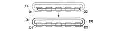
隣接して接続されていた装置の消滅を検出したとき、図11のステップS21において、当該装置は、第1N_I/Oの2つの端子のうち一方(オーディオネットワークの上流側又は下流側のうち、隣接装置の消滅を検出した側)に、伝送フレームの折り返し経路(ループバック(LB))に設定する。図15は隣接装置の消滅によるネットワーク構成の変化を説明する図である。リング状のネットワークの一部接続(D1,D2間の接続)が切断すると((a)の状態)、切断部分の各装置D1,D2にはそれぞれ折り返し経路(LB)が形成され、当該ネットワークは装置D1,D2を端部とするカスケード状の接続形態になる((b)の状態)。<When the adjacent device disappears>
When the disappearance of the adjacently connected device is detected, in step S21 in FIG. 11, the device is connected to one of the two terminals of the first N_I / O (on the upstream side or the downstream side of the audio network. On the side where the disappearance of the device is detected, a transmission frame return path (loop back (LB)) is set. FIG. 15 is a diagram for explaining changes in the network configuration due to the disappearance of adjacent devices. When a partial connection (connection between D1 and D2) of the ring-shaped network is disconnected (state (a)), a loopback path (LB) is formed in each of the devices D1 and D2 at the disconnected part, and the network It becomes a cascaded connection form with the devices D1 and D2 as ends (state (b)).
ステップS22において、隣接装置の消滅を検出した当該装置は、自身が属するネットワークのデバイスリストの内容を更新する。このデバイスリスト更新により当該装置の上側又は下側の行には接続状態を示す情報として「open」が書き込まれる。「open」が書き込まれる行の位置は、消滅した側が、当該装置に対してオーディオネットワークの上流側か下流側かに応じて異なる。もともとカスケードネットワークであった場合(リストに既に「open」が記載されていた場合)は、デバイスリストから、新たに書き込んだ「open」の該消滅した側の装置の情報を、該既存の「open」まで全て削除する。もともとリングネットワークであった場合(リストに「loop」が記載されていた場合)は、デバイスリストから何れの装置の情報も削除することなく、「loop」記号だけを削除する。例えば、図15の場合、装置D1の当初のデバイスリストは{D1,D2,D*,D*,D*,loop}であり、切断後は、{D1,open,D2,D*,D*,D*}に更新され、また、装置D2の当初のデバイスリストは{D2,D*,D*,D*,D1,loop}であり、切断後は、{D2,D*,D*,D*,D1,open}に更新される。ステップS23において、更新されたデバイスリストの内容を、当該装置に接続されている全ての装置に対して通知する。通知を受けた各装置は、図12の処理により、その装置内に記憶されているデバイスリストの内容を更新する。通知をする範囲は、前記ステップS18と同様に、当該装置が属するネットワーク内の全ての装置、及び、そのネットワークに対して接続ノードを介してフルブリッジ又はパーシャルブリッジ設定で接続された全ネットワークである。例えば、図15の場合、装置D1を起点として、装置D2が切断されたことを示す情報が他の装置に通知されるとともに、装置D2を起点として、装置D1が切断されたことを示す情報が他の装置に通知され、通知を受けた各装置のデバイスリストが更新される。 In step S22, the device that has detected the disappearance of the adjacent device updates the contents of the device list of the network to which it belongs. By this device list update, “open” is written in the upper or lower row of the apparatus as information indicating the connection state. The position of the line in which “open” is written differs depending on whether the extinguished side is upstream or downstream of the audio network with respect to the device. When the network is originally a cascade network (when “open” has already been described in the list), information on the device on the extinguished side of the newly written “open” is stored in the existing “open” from the device list. ”Is deleted. If the network is originally a ring network (when “loop” is described in the list), only the “loop” symbol is deleted without deleting any device information from the device list. For example, in the case of FIG. 15, the initial device list of the device D1 is {D1, D2, D *, D *, D *, loop}, and after disconnection, {D1, open, D2, D *, D *. , D *}, and the initial device list of the device D2 is {D2, D *, D *, D *, D1, loop}, and after disconnection, {D2, D *, D *, D *, D1, open}. In step S23, the updated contents of the device list are notified to all apparatuses connected to the apparatus. Receiving the notification, each device updates the contents of the device list stored in the device by the processing of FIG. As in step S18, the notification range is all devices in the network to which the device belongs, and all networks connected to the network through a connection node with a full bridge or partial bridge setting. . For example, in the case of FIG. 15, information indicating that the device D2 has been disconnected from the device D1 is notified to other devices, and information indicating that the device D1 has been disconnected from the device D2 is the starting point. Other devices are notified, and the device list of each device receiving the notification is updated.
図12のフローチャートは、前記ステップS18又はS23によるデバイスリスト更新通知を受信したときに、その装置が実行する処理例を示す。ステップS24において、その装置のCPUは、受信した更新内容に基づいて、その装置内のメモリに記憶された、対応するデバイスリストを、通知元の装置で行われた更新と同様に、更新する。その装置が接続ノードである場合(ステップS25のyes)、ステップS26において、その装置は、受信したデバイスリスト更新通知を、接続ノードを介した接続先のネットワークの全ての装置に対して通知する。接続ノードは2つのネットワークを接続する部分であるから、接続ノードの接続先のネットワークとは、更新内容を受信したネットワークに対して他のネットワークである。接続ノードの接続先のネットワークにも更新内容を通知するので、互いに接続された全てのネットワークの全ての装置(図1で示す接続例の全体)がデバイスリスト更新内容を受信し、記憶しているデバイスリストを更新することができる。 The flowchart in FIG. 12 shows an example of processing executed by the apparatus when the device list update notification in step S18 or S23 is received. In step S24, the CPU of the device updates the corresponding device list stored in the memory in the device based on the received update content, in the same manner as the update performed in the notification source device. If the device is a connection node (yes in step S25), in step S26, the device notifies the received device list update notification to all devices in the network to which the connection is made via the connection node. Since the connection node is a part that connects two networks, the network to which the connection node is connected is a network other than the network that has received the updated content. Since the update contents are also notified to the connection destination network of the connection node, all devices (all connection examples shown in FIG. 1) of all the networks connected to each other receive and store the device list update contents. The device list can be updated.
このように、個々のネットワークの構成が変更される毎に、全ての装置が持つ当該ネットワークのデバイスリストが更新される。よって、オーディオネットワークビュー画面には、常に、現在のオーデクイネットワークシステム100の接続態様を表示することができる。 In this way, every time the configuration of an individual network is changed, the device list of the network possessed by all apparatuses is updated. Therefore, the current connection mode of the
デバイスリストが、各装置のオーディオネットワーク通信機能(詳しくはオーディオネットワークの通信プロトコルの階層モデルにおけるMAC層)により更新・作成されるものであり、単に物理的に接続された装置を記録するのではなく、伝送フレームの伝送経路が形成された装置の接続状態を記録したものであるため、ユーザは、デバイスリストに基づくネットワークビュー画面の表示により伝送フレームが実際に流れている経路に対応するネットワークの接続状態を確認できる。また、各ネットワークのデバイスリストには、接続されている複数の装置が、その接続順にリストされており、ネットワークビュー画面の表示では、各装置の上流にどの装置が接続されており、下流にどの装置が接続されているかを確認できる。 The device list is updated and created by the audio network communication function of each device (specifically, the MAC layer in the hierarchical model of the audio network communication protocol), not simply recording the physically connected devices. Since the connection state of the device in which the transmission path of the transmission frame is formed is recorded, the user can connect to the network corresponding to the path through which the transmission frame actually flows by displaying the network view screen based on the device list. You can check the status. In the device list of each network, a plurality of connected devices are listed in the order of connection. In the display of the network view screen, which device is connected upstream of each device and which device is connected downstream. You can check if the device is connected.
《デバイスリストの更新:接続ノードとしての動作開示時》
第1N_I/Oを介して第1のネットワークに接続された装置の第2N_I/Oの何れかの端子が、第1のネットワークに属していない他の装置の何れかのN_I/Oの何れかの端子と接続されたとき、上述したステップS13と同様に、当該装置は相手装置と接続の可否について交渉する。交渉が成立すると、ステップS15乃至ステップS20と同様に、少なくとも当該装置と相手装置とを含む、第2のネットワークの伝送フレームの伝送経路が形成され、当該装置は、第1のネットワークと第2のネットワークを接続する接続ノード(ブリッジ)となる。両側のネットワークで伝送フレームが巡回し始めた時点で、当該装置は、イーサネット(登録商標)領域43のデータのブリッジを開始する。すなわち、各一方のネットワークにおいてイーサネット(登録商標)領域に書き込まれたイーサネット(登録商標)形式のフレームデータを、そのアドレスに従って、必要に応じて他方のネットワークの伝送フレームのイーサネット(登録商標)領域に書き込む(ルーティングする)。
この状況において、当該装置が、第1のネットワークと第2のネットワークの少なくとも一方におけるマスタノードとして動作していれば、第1のネットワークと第2のネットワークの伝送フレームの送信周期、すなわち、オーディオ信号のサンプリングクロックが相互に同期し、一方のネットワークのオーディオ信号を他方のネットワークに流す条件が整ったことになるので、当該装置は、ブリッジ設定に従い音響信号のブリッジ動作を開始する。すなわち、当該装置のブリッジ設定が、フルブリッジモードに設定されていた場合は、各一方のネットワークにおいて伝送フレームに書き込まれた全てのN伝送chのオーディオ信号を他方のネットワークの伝送フレームの同じN伝送chに書き込み、パーシャルブリッジモードに設定されていた場合は、各一方のネットワークにおいて伝送フレームに書き込まれたN伝送chのオーディオ信号のうちの、転送が設定されたN伝送chのオーディオ信号を、他方のネットワークの当該装置に割り当てられたN伝送chに書き込む。
イーサネット(登録商標)形式のフレームデータのルーティングが開始されると、一方のネットワークの何れかの装置で行われたデバイスリストの更新が、当該装置越しに、他方のネットワークの各装置にも通知され、該通知によって、2つのネットワークの全装置のデバイスリストが更新されるようになる。この場合のデバイスリスト更新の手順は、基本的に、単一のネットワークの場合と同様である。当該装置は、まず、自身が保有している第1ネットワークのデバイスリストの情報を、第2ネットワークの隣接する装置に通知するとともに、該第2ネットワークの隣接する装置より、第2ネットワークのデバイスリストの情報を受け取る。そして、受け取った第2ネットワークの情報に基づいて、自身の機器IDとその情報に含まれる第2ネットワークの各装置の機器IDとを含む第2ネットワークのデバイスリストを生成するとともに、該生成したデバイスリストの情報を、第1ネットワークの各装置に通知する。
なお、第2N_I/Oでの新規接続が検出されたとき、ステップS13での交渉が不成立(接続否)であった場合は、第2N_I/Oには何の接続も行われていないのと等価であり、この接続に関して新たなデバイスリストは作成されない。<Updating device list: When disclosing operation as a connection node>
Any terminal of the second N_I / O of the device connected to the first network via the first N_I / O is one of the N_I / O of any of the other devices not belonging to the first network. When connected to the terminal, the device negotiates with the counterpart device whether the connection is possible, as in step S13 described above. When the negotiation is established, similarly to steps S15 to S20, a transmission path of a transmission frame of the second network including at least the device and the counterpart device is formed, and the device is connected to the first network and the second network. It becomes a connection node (bridge) that connects networks. When the transmission frame starts to circulate in the networks on both sides, the apparatus starts bridging the data in the Ethernet (registered trademark)
In this situation, if the device is operating as a master node in at least one of the first network and the second network, the transmission period of the transmission frame of the first network and the second network, that is, the audio signal Since the sampling clocks are synchronized with each other and the condition for flowing the audio signal of one network to the other network is ready, the apparatus starts the bridge operation of the acoustic signal according to the bridge setting. That is, when the bridge setting of the device is set to the full bridge mode, the audio signals of all N transmission channels written in the transmission frame in each one network are transmitted in the same N transmission in the transmission frame of the other network. When the channel is written in the channel and the partial bridge mode is set, the audio signal of the N transmission channel in which the transfer is set out of the audio signals of the N transmission channels written in the transmission frame in each one of the networks. Write to the N transmission channels assigned to the device in the network.
When the routing of frame data in the Ethernet (registered trademark) format is started, the update of the device list performed by any device in one network is notified to each device in the other network through the device. The notification causes the device lists of all the devices in the two networks to be updated. The device list update procedure in this case is basically the same as in the case of a single network. The apparatus first notifies the information of the device list of the first network held by itself to an adjacent device of the second network, and from the adjacent device of the second network, the device list of the second network Receive information. Based on the received second network information, a device list of the second network including its own device ID and the device ID of each device of the second network included in the information is generated, and the generated device The list information is notified to each device of the first network.
When a new connection at the second N_I / O is detected, if the negotiation at step S13 is not established (connection is not allowed), it is equivalent to no connection being made at the second N_I / O. No new device list is created for this connection.
以上説明した通り、本実施例によりオーディオネットワークビュー画面を表示することで、ユーザは、複数のネットワークからなるシステム100の接続態様について、各ネットワークを構成する装置数、装置種類、各ネットワークを構成する複数装置の接続順を画面から認識できる。また、ユーザは、オーディオネットワークビュー画面から各ネットワークの接続形態(カスケード状かリング状か)を認識でき、カスケードの場合、どの2つの装置をループすればよいのかも簡単に認識できる。また、ユーザは、オーディオネットワークビュー画面から、接続ノードを介して接続された2つのネットワークがフルブリッジ設定で接続されているのか、パーシャルブリッジ設定で接続されているのかを認識できる。また、フルブリッジ設定の場合、そのネットワーク構成が表示されるので、ユーザは、オーディオネットワークビュー画面から、1つのシステム100として制御装置でリモート制御できる全範囲の装置構成を、簡単に認識できる。 As described above, by displaying the audio network view screen according to the present embodiment, the user configures the number of devices configuring each network, the device type, and each network with respect to the connection mode of the
なお、図6のオーディオネットワークビュー画面において、最上段61aには、基本ネットワークとして、その画面を表示する装置が属するネットワークが表示される構成(その画面を表示する装置に応じて基本ネットワークが変化する構成)を説明したが、システム100中の1つのネットワークが固定的に基本ネットワークとなってもよい。つまり、各装置が持つ各ネットワーク毎のデバイスリストのうち1つが基本ネットワーク用のデバイスリストとして固定さされてもよい。
また、図6のオーディオネットワークビュー画面における各表示段61a〜61fにおける各装置画像62の表示順(接続順の表示)が、その画面を表示する装置に応じて変化する構成を説明したが、各ネットワークにおける各装置画像62の表示順(接続順の表示)が固定される構成であってもよい。つまり、各装置が持つ各ネットワーク毎のデバイスリストにおける装置の記録順を全ての装置で共通する順番に固定してもよい。In the audio network view screen of FIG. 6, a configuration in which the network to which the device that displays the screen belongs is displayed as the basic network in the uppermost 61a (the basic network changes according to the device that displays the screen). Configuration) has been described, but one network in the
Moreover, although the display order (display of connection order) of each
なお、上記の説明では、接続ノードの画像62は、その装置の第1N_I/Oを介して接続されたネットワークの表示段(2つのネットワークを表示する表示段うち上段側)に表示されるものとしたが、接続ノードの画像62が、その装置の第2N_I/Oを介して接続されたネットワークの表示段(2つのネットワークを表示する表示段うち下段側)に表示されてもよい。また、接続ノードの画像62が2つのネットワークの両方の表示段に表示されてもよい。 In the above description, the
また、全ての装置が2つのN_I/Oを有する必要はなく、少なくとも接続ノードとなる装置だけがN_I/Oを2つ有していればよい。また、接続ノードは、複数のネットワークをフルブリッジ接続あるいはパーシャルブリッジ接続する場合にネットワーク中に少なくとも1つあればよい。
なお、パーシャルブリッジで接続された別のネットワークに関しては、必ずしも、装置の接続順を検出しデバイステーブルを作成する必要はない。Further, it is not necessary for all devices to have two N_I / Os, and at least only a device that becomes a connection node needs to have two N_I / Os. Further, at least one connection node may be included in a network when a plurality of networks are connected in a full bridge connection or a partial bridge connection.
For another network connected by a partial bridge, it is not always necessary to detect the connection order of devices and create a device table.
本実施形態の2つの信号処理エンジン(DSP_A,DSP_B)は、二重化のためのミラーリング動作を行うようになっていたが、それぞれ独立に、異なる信号処理を行わせ、それにより、ミキシング処理の規模を拡張してもよい。 The two signal processing engines (DSP_A, DSP_B) of the present embodiment are designed to perform mirroring operations for duplexing. However, different signal processing is performed independently of each other, thereby reducing the scale of the mixing processing. It may be expanded.
以上の説明において、各ノードは、それぞれ、1又は2のオーディオネットワークに接続するための1又は2のインターフェースを有するとしたが、3以上のインターフェースを有していてもよい。
以上の説明において、各ノードのインターフェースはオーディオネットワークに接続するための方向性を有する一組(2つ)の端子を有するとしたが、3以上の端子を有していてもよい。
以上の説明において、ブリッジ設定手段は、該設定操作に応じて、制御装置および当該接続ノードの各カレントメモリに記憶された当該接続ノードの2つのN_I/Oのパラメータを設定する。また、ブリッジ設定手段の動作は、個々の接続ノード(ブリッジ)のCPUがユーザの指示に応じて、自身の設定に関する制御を行っても良いし、或いは、制御装置又はマスタノードにより各接続ノードにけるブリッジ設定をリモート制御してもよい。
以上の説明において、オーディオネットワークビュー画面は、基本ネットワークを最上段とし、画面下方向に他のネットワークを段階的に表示する態様にて説明したが、表示画面における左から右方向、右から左方向、下から上方向、中心から外周方向等種々の表示態様を採用してもよい。あるいは表示画面に対して略直交する仮想的な奥行き空間を定義し、奥行き方向あるいは手前方向等任意の方向に各階層を三次元的に表示するようにしてもよい。この場合、表示画面として立体液晶等の三次元表示可能なディスプレイ装置を採用し、裸眼あるいはシャッターグラス等を用いた三次元表示を行うようにしてもよい。あるいは1又は複数の表示レイヤを設け、レイヤ毎に個々のネットワークを描画することにより複数のネットワークを重畳させて表示する等、上記三次元的に配置した各層のネットワークを平面に投影した状態にて表示してもよい。この場合レイヤあるいはネットワーク毎に、表示順序を入れ替え可能としたり、描画配色や描画色の輝度を異ならせたり、描画する線や文字のサイズを異ならせる等することが望ましい。また、これら表示態様を適宜組み合わせても良い。In the above description, each node has one or two interfaces for connecting to one or two audio networks, but may have three or more interfaces.
In the above description, the interface of each node is assumed to have a pair (two) of terminals having directivity for connection to the audio network, but may have three or more terminals.
In the above description, the bridge setting means sets the two N_I / O parameters of the connection node stored in the current memories of the control device and the connection node in accordance with the setting operation. In addition, the operation of the bridge setting means may be such that the CPU of each connection node (bridge) performs control related to its own setting in accordance with a user instruction, or each control node or master node controls each connection node. The bridge setting may be remotely controlled.
In the above description, the audio network view screen has been described in a mode in which the basic network is the top level and other networks are displayed stepwise in the lower direction of the screen. However, the left to right direction and the right to left direction on the display screen are described. Various display modes, such as from the bottom to the top and from the center to the outer periphery, may be employed. Alternatively, a virtual depth space substantially orthogonal to the display screen may be defined, and each layer may be displayed three-dimensionally in an arbitrary direction such as the depth direction or the front direction. In this case, a display device capable of three-dimensional display such as a three-dimensional liquid crystal may be adopted as the display screen, and three-dimensional display using the naked eye or shutter glass may be performed. Alternatively, in a state where one or a plurality of display layers are provided, and the networks of the respective layers arranged in a three-dimensional manner are projected onto a plane, such as displaying each of the networks superimposed on each layer by drawing each network. It may be displayed. In this case, it is desirable to be able to change the display order for each layer or network, to change the drawing color scheme or the luminance of the drawing color, or to change the size of the line or character to be drawn. Moreover, you may combine these display modes suitably.
100 オーディオネットワークシステム、110,111 PC、1 ミキシングシステム、2、3コンソール、4,5 信号処理エンジン、6〜8 入出力装置、10,20,30 CPU、11,21,31 メモリ、12、22,32 PC_I/O、13,23,33 オーディオI/O、14,24,34 第1ネットワークI/O、15,25,35、 第2ネットワークI/O、16 P表示部、60 ネットワーク表示領域、61a〜61d 表示段、62 装置画像、63 装置名、64 第1N_I/O画像、65 第2N_I/O画像、66 接続ケーブル画像、67 パーシャルブリッジ画像100 audio network system, 110, 111 PC, 1 mixing system, 2, 3 console, 4,5 signal processing engine, 6-8 input / output device, 10, 20, 30 CPU, 11, 21, 31 memory, 12, 22 , 32 PC_I / O, 13, 23, 33 Audio I / O, 14, 24, 34 First network I / O, 15, 25, 35, Second network I / O, 16 P display section, 60
Claims (11)
Translated fromJapanese前記装置が、それぞれ、第1端子及び第2端子を備えるネットワークインターフェースを少なくとも1つ有し、前記カスケードネットワークとは、1台目の装置の前記ネットワークインターフェースの前記第2端子と、2台目の装置の前記ネットワークインターフェースの前記第1端子との間をケーブルを用いて連結し、該2台目の装置の前記ネットワークインターフェースの前記第2端子と、3台目の装置の前記ネットワークインターフェースの前記第1端子とをケーブルを用いて連結し、この連結を順次繰り返すことにより形成されるものであり、また、前記リングネットワークとは、前記カスケードネットワークの終端の装置のネットワークインターフェースの第2端子と、該カスケードネットワークにおける先端の装置のネットワークインターフェースの第1端子とをケーブルを用いて連結することにより形成されるものであり、
前記オーディオネットワークシステムにおいて、
カスケー又はリングネットワーク状に連結された複数の装置を巡るリング状伝送経路を形成する経路形成部と、
前記装置の1つをマスタノードとして指定する指定部であって、該マスタノードに指定された装置が所定周期毎に伝送フレームを生成して該伝送フレームを前記伝送経路に送出し、複数のオーディオ信号と制御データとを載せた前記伝送フレームが前記リング状伝送経路に沿って前記複数の装置の間を巡回するものである指定部と、
1つの装置を送信元として指定し、且つ、別の装置を受信先として指定するオーディオ信号経路制御部であって、送信元に指定された前記装置は前記伝送フレームが当該装置を通過している間にオーディオ信号を該伝送フレームに書き込み、受信先に指定された前記装置は前記伝送フレームが当該装置を通過している間に前記オーディオ信号を該伝送フレームから読み出すものであるオーディオ信号経路制御部と、
前記巡回する伝送フレームを通じて前記制御装置から前記各装置に制御データを送信して、前記制御データに従って前記装置を制御する制御部と
を備えており、
前記経路形成部は、ケーブルを用いてカスケード状に連結され、前記リング状伝送経路が既に形成されている複数の装置のうちの端部の装置を使って、ケーブルを用いてカスケード状又はリング状に連結された各装置と交渉し、前記装置からの応答が肯定であった場合に該装置を前記リング状伝送経路に組み込み、
前記オーディオネットワークシステムは、更に、
前記1つのネットワークの前記リング状伝送経路上にある複数の装置と、前記ケーブルによるそれら複数の装置の連結順とを検出する第1検出部と、
前記検出された前記1つのネットワークの前記リング状伝送経路上の装置の画像を、該複数の装置の画像を連結するケーブル画像とともに、前記検出された連結順で、前記制御装置のディスプレイにグラフィカルに表示する表示部と
を備えることを特徴とする。It consists of at least one network including one or a plurality of devices connected by a cable in a cascade network shape or a ring network shape, and a control device connected to one of the devices or provided in one of the devices An audio network system,
Each of the devices has at least one network interface including a first terminal and a second terminal, and the cascade network is the second terminal of the network interface of the first device and the second device. And connecting the first terminal of the network interface of a device using a cable, the second terminal of the network interface of the second device, and the first of the network interface of a third device. The ring network is formed by connecting one terminal to each other using a cable and sequentially repeating the connection, and the ring network includes a second terminal of a network interface of a terminal device of the cascade network, Advanced device network in cascade network And those formed by coupling the first terminal of the interface with the cable,
In the audio network system,
A path forming unit that forms a ring-shaped transmission path around a plurality of devices connected in a cascade or ring network;
A designation unit that designates one of the devices as a master node, wherein the device designated as the master node generates a transmission frame at a predetermined period, sends the transmission frame to the transmission path, and transmits a plurality of audio signals; A designation unit in which the transmission frame carrying a signal and control data circulates between the plurality of devices along the ring-shaped transmission path;
An audio signal path control unit that designates one device as a transmission source and designates another device as a reception destination, wherein the transmission frame passes through the device designated as the transmission source. An audio signal path control unit that writes an audio signal to the transmission frame in between, and the device designated as the reception destination reads out the audio signal from the transmission frame while the transmission frame passes through the device When,
A control unit that transmits control data from the control device to the devices through the circulating transmission frame, and controls the device according to the control data; and
The path forming unit is connected in a cascade using a cable, and an end device among a plurality of devices in which the ring-shaped transmission path is already formed is used to form a cascade or a ring using a cable. Negotiate with each device connected to the device, and if the response from the device is positive, incorporate the device into the ring-shaped transmission path,
The audio network system further includes:
A first detector that detects a plurality of devices on the ring-shaped transmission path of the one network and a connection order of the plurality of devices by the cable;
The detected image of the device on the ring transmission path of the one network is graphically displayed on the display of the control device in the detected connection order together with the cable image connecting the images of the plurality of devices. And a display unit for displaying.
前記別のネットワークが、カスケードネットワーク又はリングネットワークの形状にケーブルにより連結された1又は複数の装置を含み、前記リング状伝送経路が該複数の装置に形成され、前記複数の装置の1つが、所定周期毎に伝送フレームを生成して該伝送フレームを前記伝送経路に送出するマスタノードとして動作し、複数のオーディオ信号と制御データとを搬送する前記伝送フレームが前記リング状伝送経路に沿って複数の装置の間を巡回し、或る装置が当該装置を通過している間にオーディオ信号を該伝送フレームに書き込み、別の装置は前記伝送フレームが当該別の装置を通過している間に前記オーディオ信号を該伝送フレームから読み出し、
前記ブリッジ装置が、前記1つのネットワーク及び前記別のネットワークのいずれか一方の伝送フレームから前記オーディオ信号及び前記制御データを読み出し、前記1つのネットワーク及び前記別のネットワークのいずれか他方の伝送フレームに前記オーディオ信号及び前記制御データを書き込み、前記制御装置が、前記伝送フレームを通じて該制御装置に送信されたコントロールに従って、前記リング状伝送経路上の前記複数の装置をリモート制御するものであり、
前記オーディオネットワークシステムにおいて、
前記別のネットワークの前記リング状伝送経路上にある複数の装置を検出し、且つ、前記ケーブルによるそれら複数の装置の連結順とを検出する第2検出部を更に備え、
前記表示部が、更に、前記検出された前記別のネットワークのリング状伝送経路上の複数の装置の画像を、前記ブリッジ装置の画像に1又は2のケーブル画像により連結して、該複数の装置の画像を連結するケーブル画像とともに、前記検出された連結順で、前記制御装置のディスプレイにグラフィカルに表示する
ことを特徴とする請求項1に記載のオーディオネットワークシステム。At least one device on the ring-shaped transmission path is a bridge device having another network interface connected to another network in the audio network system, and the other network is connected to one network by the bridge device. Are concatenated,
The another network includes one or a plurality of devices connected by cables in the form of a cascade network or a ring network, the ring-shaped transmission path is formed in the plurality of devices, and one of the plurality of devices is a predetermined one. It operates as a master node that generates a transmission frame for each period and sends the transmission frame to the transmission path, and the transmission frame carrying a plurality of audio signals and control data is connected to the plurality of ring-shaped transmission paths. Circulates between devices, writes an audio signal to the transmission frame while one device passes through the device, and another device transmits the audio signal while the transmission frame passes through the other device. Reading a signal from the transmission frame;
The bridge device reads the audio signal and the control data from one of the transmission frames of the one network and the other network, and transmits the audio signal and the control data to the other transmission frame of the one network and the other network. An audio signal and the control data are written, and the control device remotely controls the plurality of devices on the ring-shaped transmission path according to the control transmitted to the control device through the transmission frame.
In the audio network system,
A second detector for detecting a plurality of devices on the ring-shaped transmission path of the another network and detecting a connection order of the plurality of devices by the cable;
The display unit further connects the detected images of the plurality of devices on the ring-shaped transmission path of the other network to the image of the bridge device by one or two cable images, and the plurality of devices. 2. The audio network system according to claim 1, wherein the image is graphically displayed on a display of the control device in the detected connection order together with a cable image connecting the two images.
前記表示部が、前記ケーブル画像のそれぞれを方向性とともに表示することを特徴とする請求項1に記載のオーディオネットワークシステム。The connection between the two devices has a unidirectional direction, the first terminal of one device is connected to the second terminal of the device adjacent to the upstream side of the one device, and the first terminal of the one device is connected. Two terminals are connected to a first terminal of a device adjacent to the downstream side of the one device;
The audio network system according to claim 1, wherein the display unit displays each of the cable images together with directionality.
前記表示部は、前記ブリッジ装置がフルブリッジモードに設定されている場合、前記検出された前記別のネットワークのリング状伝送経路上の複数の装置の画像を表示し、また前記ブリッジ装置がパーシャルブリッジモードに設定されている場合には、前記検出された前記別のネットワークのリング状伝送経路上の複数の装置の画像の代わりに、パーシャルブリッジ画像を表示することを特徴とする請求項5に記載のオーディオネットワークシステム。The bridge device is set to either a full bridge mode in which another network is combined with one network as an extension of the network, or a partial bridge mode in which another network and one network are combined as an independent network. And
The display unit displays images of a plurality of devices on the detected ring-shaped transmission path of the other network when the bridge device is set to a full bridge mode, and the bridge device is a partial bridge. The partial bridge image is displayed in place of the detected image of a plurality of devices on the ring-shaped transmission path of the other network when the mode is set. Audio network system.
前記複数の装置の協働は、
前記複数の装置の1つにおいて、装置リストを準備する準備手順と、
前記複数の装置のそれぞれにおいて、その装置に隣接する装置の情報、又は、前記1つのネットワークの前記リング状伝送経路上のその装置の位置の情報を検出する検出手順と、
前記複数の装置のそれぞれにおいて、前記検出された情報を前記複数の装置の1つに通知する通知手順と、
前記複数の装置の1つにおいて、前記複数の装置のそれぞれから通知された情報に従って、前記1つのネットワークのリング状伝送経路上の複数の装置の情報を、該複数の装置が前記ケーブルによって連結されている連結順で、前記準備した装置リストに書き込む書き込み手順
からなるものであることを特徴とする請求項1に記載のオーディオネットワークシステム。The first detection unit detects a plurality of devices on the ring-shaped transmission path of the one network and a connection order thereof by cooperation of the plurality of devices on the ring-shaped transmission path of the one network. Is,
The cooperation of the plurality of devices is
A preparation procedure for preparing a device list in one of the plurality of devices;
In each of the plurality of devices, a detection procedure for detecting information on a device adjacent to the device or information on a position of the device on the ring-shaped transmission path of the one network;
A notification procedure for notifying one of the plurality of devices of the detected information in each of the plurality of devices;
In one of the plurality of devices, in accordance with information notified from each of the plurality of devices, information on the plurality of devices on the ring-shaped transmission path of the one network is connected by the cable. 2. The audio network system according to claim 1, comprising a writing procedure for writing in the prepared device list in a connected order.
Priority Applications (3)
| Application Number | Priority Date | Filing Date | Title |
|---|---|---|---|
| JP2011064709AJP2011223567A (en) | 2010-03-24 | 2011-03-23 | Audio network system and display method |
| US13/636,854US20130010647A1 (en) | 2010-03-24 | 2011-03-24 | Audio Network System and Display Method |
| PCT/JP2011/057167WO2011118702A1 (en) | 2010-03-24 | 2011-03-24 | Audio network system and display method |
Applications Claiming Priority (3)
| Application Number | Priority Date | Filing Date | Title |
|---|---|---|---|
| JP2010068940 | 2010-03-24 | ||
| JP2010068940 | 2010-03-24 | ||
| JP2011064709AJP2011223567A (en) | 2010-03-24 | 2011-03-23 | Audio network system and display method |
Publications (1)
| Publication Number | Publication Date |
|---|---|
| JP2011223567Atrue JP2011223567A (en) | 2011-11-04 |
Family
ID=44673248
Family Applications (1)
| Application Number | Title | Priority Date | Filing Date |
|---|---|---|---|
| JP2011064709APendingJP2011223567A (en) | 2010-03-24 | 2011-03-23 | Audio network system and display method |
Country Status (3)
| Country | Link |
|---|---|
| US (1) | US20130010647A1 (en) |
| JP (1) | JP2011223567A (en) |
| WO (1) | WO2011118702A1 (en) |
Families Citing this family (1)
| Publication number | Priority date | Publication date | Assignee | Title |
|---|---|---|---|---|
| EP2939384B1 (en)* | 2012-12-27 | 2019-02-27 | Robert Bosch GmbH | Audio stream arrangement |
Citations (3)
| Publication number | Priority date | Publication date | Assignee | Title |
|---|---|---|---|---|
| JPH08298517A (en)* | 1995-04-19 | 1996-11-12 | Hewlett Packard Co <Hp> | How to build and display a physical connectivity map |
| JP2004072137A (en)* | 2002-08-01 | 2004-03-04 | Alpine Electronics Inc | Signal transmission system and audio system |
| JP2007259347A (en)* | 2006-03-24 | 2007-10-04 | Yamaha Corp | Network system and acoustic signal processing apparatus |
Family Cites Families (13)
| Publication number | Priority date | Publication date | Assignee | Title |
|---|---|---|---|---|
| US6154465A (en)* | 1998-10-06 | 2000-11-28 | Vertical Networks, Inc. | Systems and methods for multiple mode voice and data communications using intelligenty bridged TDM and packet buses and methods for performing telephony and data functions using the same |
| US6181694B1 (en)* | 1998-04-03 | 2001-01-30 | Vertical Networks, Inc. | Systems and methods for multiple mode voice and data communciations using intelligently bridged TDM and packet buses |
| US7987224B2 (en)* | 2007-10-03 | 2011-07-26 | Yamaha Corporation | Audio signal processor and network system |
| US7200144B2 (en)* | 2001-10-18 | 2007-04-03 | Qlogic, Corp. | Router and methods using network addresses for virtualization |
| US7050395B1 (en)* | 2001-11-30 | 2006-05-23 | Redback Networks Inc. | Method and apparatus for disabling an interface between network element data processing units |
| US8437284B2 (en)* | 2003-07-29 | 2013-05-07 | Citrix Systems, Inc. | Systems and methods for additional retransmissions of dropped packets |
| US8244883B2 (en)* | 2006-08-03 | 2012-08-14 | Citrix Systems, Inc. | Systems and methods of for providing multi-mode transport layer compression |
| JP4187028B2 (en)* | 2006-09-13 | 2008-11-26 | ヤマハ株式会社 | Network system and acoustic signal processing apparatus |
| EP1901483B1 (en)* | 2006-09-13 | 2014-11-05 | Yamaha Corporation | Network system and audio signal processor |
| EP2178250B1 (en)* | 2008-10-15 | 2011-12-07 | Yamaha Corporation | Audio Network System |
| JP5476889B2 (en)* | 2009-09-28 | 2014-04-23 | ヤマハ株式会社 | Network system |
| JP5589727B2 (en)* | 2009-09-29 | 2014-09-17 | ヤマハ株式会社 | Network system |
| JP5454255B2 (en)* | 2010-03-16 | 2014-03-26 | ヤマハ株式会社 | Acoustic signal processing apparatus and acoustic signal processing system |
- 2011
- 2011-03-23JPJP2011064709Apatent/JP2011223567A/enactivePending
- 2011-03-24WOPCT/JP2011/057167patent/WO2011118702A1/enactiveApplication Filing
- 2011-03-24USUS13/636,854patent/US20130010647A1/ennot_activeAbandoned
Patent Citations (3)
| Publication number | Priority date | Publication date | Assignee | Title |
|---|---|---|---|---|
| JPH08298517A (en)* | 1995-04-19 | 1996-11-12 | Hewlett Packard Co <Hp> | How to build and display a physical connectivity map |
| JP2004072137A (en)* | 2002-08-01 | 2004-03-04 | Alpine Electronics Inc | Signal transmission system and audio system |
| JP2007259347A (en)* | 2006-03-24 | 2007-10-04 | Yamaha Corp | Network system and acoustic signal processing apparatus |
Also Published As
| Publication number | Publication date |
|---|---|
| US20130010647A1 (en) | 2013-01-10 |
| WO2011118702A1 (en) | 2011-09-29 |
Similar Documents
| Publication | Publication Date | Title |
|---|---|---|
| CN108173691B (en) | Cross-device aggregation method and device | |
| JP4899568B2 (en) | Network system and acoustic signal processing apparatus | |
| JP5076413B2 (en) | Network system and acoustic signal processing apparatus | |
| JP5159852B2 (en) | Node, switch and system | |
| JP2008072347A (en) | Network system and acoustic signal processing apparatus | |
| JP2008167315A (en) | Redundant line connection method and wide area network node device | |
| CN110401558A (en) | Safety level multi-point communication network equipment, system and safety level network communication method | |
| US9843506B2 (en) | Distributed control system and control method thereof | |
| JP2008099265A (en) | Network system | |
| EP2367323B1 (en) | Audio signal processor and audio signal processing system | |
| CN106465454B (en) | Wireless communication system and communication method | |
| CN101425945A (en) | System or local area network implementing method for computer | |
| JP2016181795A (en) | Network system and network setting method | |
| CN114157606B (en) | Virtual network element device switching method, device and storage medium | |
| WO2011118702A1 (en) | Audio network system and display method | |
| JP5088078B2 (en) | Network system and communication device | |
| US8824333B2 (en) | Method and apparatus for full duplex serial shifting mode and switch mode data transmission | |
| CN101009625A (en) | A real-time loop monitoring network system | |
| JP5012382B2 (en) | Acoustic signal processing apparatus and network system | |
| JP2007164120A (en) | Control apparatus for music system comprising a plurality of equipment connected together through network and integrated software for controlling the music system | |
| JP5458961B2 (en) | Network system management method | |
| JP5045728B2 (en) | Communication node | |
| EP3008857B1 (en) | Displaying fte cable status as ucn cable status | |
| CN216356885U (en) | Bluetooth-based multi-camera synchronous communication system | |
| JP5219860B2 (en) | Domain management method, node and domain management system |
Legal Events
| Date | Code | Title | Description |
|---|---|---|---|
| A621 | Written request for application examination | Free format text:JAPANESE INTERMEDIATE CODE: A621 Effective date:20140122 | |
| A131 | Notification of reasons for refusal | Free format text:JAPANESE INTERMEDIATE CODE: A131 Effective date:20140819 | |
| A02 | Decision of refusal | Free format text:JAPANESE INTERMEDIATE CODE: A02 Effective date:20141216 |