JP2011212183A - Prefilled syringe - Google Patents
Prefilled syringeDownload PDFInfo
- Publication number
- JP2011212183A JP2011212183AJP2010082582AJP2010082582AJP2011212183AJP 2011212183 AJP2011212183 AJP 2011212183AJP 2010082582 AJP2010082582 AJP 2010082582AJP 2010082582 AJP2010082582 AJP 2010082582AJP 2011212183 AJP2011212183 AJP 2011212183A
- Authority
- JP
- Japan
- Prior art keywords
- outer cylinder
- peripheral surface
- container
- needle
- double
- Prior art date
- Legal status (The legal status is an assumption and is not a legal conclusion. Google has not performed a legal analysis and makes no representation as to the accuracy of the status listed.)
- Pending
Links
- 229940071643prefilled syringeDrugs0.000titleclaimsabstractdescription88
- 239000007788liquidSubstances0.000claimsabstractdescription126
- 230000002093peripheral effectEffects0.000claimsabstractdescription97
- 238000007789sealingMethods0.000claimsabstractdescription87
- 238000003825pressingMethods0.000claimsabstractdescription65
- 239000000126substanceSubstances0.000claimsdescription257
- 230000001681protective effectEffects0.000claimsdescription9
- 239000003814drugSubstances0.000abstractdescription36
- 238000000034methodMethods0.000abstractdescription13
- 238000004519manufacturing processMethods0.000abstractdescription7
- 239000002699waste materialSubstances0.000abstractdescription6
- 238000002360preparation methodMethods0.000abstractdescription5
- 239000000243solutionSubstances0.000description91
- 210000003491skinAnatomy0.000description80
- 239000000463materialSubstances0.000description33
- 239000008155medical solutionSubstances0.000description32
- 239000000470constituentSubstances0.000description25
- 229940079593drugDrugs0.000description25
- 238000010586diagramMethods0.000description21
- 230000000087stabilizing effectEffects0.000description17
- 229920001296polysiloxanePolymers0.000description14
- 238000012986modificationMethods0.000description13
- 230000004048modificationEffects0.000description13
- 238000003860storageMethods0.000description9
- 238000009423ventilationMethods0.000description9
- 238000012423maintenanceMethods0.000description8
- 210000000078clawAnatomy0.000description7
- 210000000852deltoid muscleAnatomy0.000description5
- 230000000694effectsEffects0.000description4
- 239000013013elastic materialSubstances0.000description4
- -1polyethylenePolymers0.000description4
- 239000011347resinSubstances0.000description4
- 229920005989resinPolymers0.000description4
- 229960005486vaccineDrugs0.000description4
- 239000011248coating agentSubstances0.000description3
- 238000000576coating methodMethods0.000description3
- 229920001971elastomerPolymers0.000description3
- 229940090044injectionDrugs0.000description3
- 238000002347injectionMethods0.000description3
- 239000007924injectionSubstances0.000description3
- 230000000149penetrating effectEffects0.000description3
- 229920000728polyesterPolymers0.000description3
- 230000002265preventionEffects0.000description3
- 230000006641stabilisationEffects0.000description3
- 238000011105stabilizationMethods0.000description3
- WQZGKKKJIJFFOK-GASJEMHNSA-NGlucoseChemical compoundOC[C@H]1OC(O)[C@H](O)[C@@H](O)[C@@H]1OWQZGKKKJIJFFOK-GASJEMHNSA-N0.000description2
- 239000004952PolyamideSubstances0.000description2
- 239000004743PolypropyleneSubstances0.000description2
- FAPWRFPIFSIZLT-UHFFFAOYSA-MSodium chlorideChemical compound[Na+].[Cl-]FAPWRFPIFSIZLT-UHFFFAOYSA-M0.000description2
- PPBRXRYQALVLMV-UHFFFAOYSA-NStyreneChemical compoundC=CC1=CC=CC=C1PPBRXRYQALVLMV-UHFFFAOYSA-N0.000description2
- 229910045601alloyInorganic materials0.000description2
- 239000000956alloySubstances0.000description2
- 230000015572biosynthetic processEffects0.000description2
- 239000003795chemical substances by applicationSubstances0.000description2
- 125000004122cyclic groupChemical group0.000description2
- 210000004207dermisAnatomy0.000description2
- 230000036512infertilityEffects0.000description2
- 238000005259measurementMethods0.000description2
- 229920002647polyamidePolymers0.000description2
- 229920000306polymethylpentenePolymers0.000description2
- 229920000098polyolefinPolymers0.000description2
- 229920001155polypropylenePolymers0.000description2
- 239000005060rubberSubstances0.000description2
- 238000007920subcutaneous administrationMethods0.000description2
- 229920000178Acrylic resinPolymers0.000description1
- 239000004925Acrylic resinSubstances0.000description1
- 229910000838Al alloyInorganic materials0.000description1
- 208000035473Communicable diseaseDiseases0.000description1
- 244000043261Hevea brasiliensisSpecies0.000description1
- VQTUBCCKSQIDNK-UHFFFAOYSA-NIsobuteneChemical groupCC(C)=CVQTUBCCKSQIDNK-UHFFFAOYSA-N0.000description1
- JHWNWJKBPDFINM-UHFFFAOYSA-NLaurolactamChemical compoundO=C1CCCCCCCCCCCN1JHWNWJKBPDFINM-UHFFFAOYSA-N0.000description1
- 241001465754MetazoaSpecies0.000description1
- 229920000299Nylon 12Polymers0.000description1
- 229920002292Nylon 6Polymers0.000description1
- 229920000305Nylon 6,10Polymers0.000description1
- 229920002302Nylon 6,6Polymers0.000description1
- 102000035195PeptidasesHuman genes0.000description1
- 108091005804PeptidasesProteins0.000description1
- 239000005062PolybutadieneSubstances0.000description1
- 239000004698PolyethyleneSubstances0.000description1
- 239000004734Polyphenylene sulfideSubstances0.000description1
- 239000004793PolystyreneSubstances0.000description1
- 229910001069Ti alloyInorganic materials0.000description1
- RTAQQCXQSZGOHL-UHFFFAOYSA-NTitaniumChemical compound[Ti]RTAQQCXQSZGOHL-UHFFFAOYSA-N0.000description1
- XECAHXYUAAWDEL-UHFFFAOYSA-Nacrylonitrile butadiene styreneChemical compoundC=CC=C.C=CC#N.C=CC1=CC=CC=C1XECAHXYUAAWDEL-UHFFFAOYSA-N0.000description1
- 239000004676acrylonitrile butadiene styreneSubstances0.000description1
- 229920000122acrylonitrile butadiene styrenePolymers0.000description1
- 239000000853adhesiveSubstances0.000description1
- 230000001070adhesive effectEffects0.000description1
- 150000001336alkenesChemical class0.000description1
- 229910052782aluminiumInorganic materials0.000description1
- XAGFODPZIPBFFR-UHFFFAOYSA-NaluminiumChemical compound[Al]XAGFODPZIPBFFR-UHFFFAOYSA-N0.000description1
- 229940035674anestheticsDrugs0.000description1
- 229940125644antibody drugDrugs0.000description1
- 239000002246antineoplastic agentSubstances0.000description1
- 230000004323axial lengthEffects0.000description1
- 238000005452bendingMethods0.000description1
- 230000003115biocidal effectEffects0.000description1
- 229920005549butyl rubberPolymers0.000description1
- 239000002872contrast mediaSubstances0.000description1
- 229920001577copolymerPolymers0.000description1
- 238000012937correctionMethods0.000description1
- 230000006837decompressionEffects0.000description1
- 238000009826distributionMethods0.000description1
- 239000000806elastomerSubstances0.000description1
- 239000003792electrolyteSubstances0.000description1
- 239000000839emulsionSubstances0.000description1
- 239000002532enzyme inhibitorSubstances0.000description1
- 210000002615epidermisAnatomy0.000description1
- 230000004927fusionEffects0.000description1
- 239000003193general anesthetic agentSubstances0.000description1
- 239000008103glucoseSubstances0.000description1
- 229940093181glucose injectionDrugs0.000description1
- 229940095529heparin calciumDrugs0.000description1
- 238000003384imaging methodMethods0.000description1
- KHYBPSFKEHXSLX-UHFFFAOYSA-NiminotitaniumChemical compound[Ti]=NKHYBPSFKEHXSLX-UHFFFAOYSA-N0.000description1
- 206010022000influenzaDiseases0.000description1
- 238000007918intramuscular administrationMethods0.000description1
- 229920003049isoprene rubberPolymers0.000description1
- 239000007769metal materialSubstances0.000description1
- 239000000203mixtureSubstances0.000description1
- 238000000465mouldingMethods0.000description1
- 239000004081narcotic agentSubstances0.000description1
- 229920003052natural elastomerPolymers0.000description1
- 229920001194natural rubberPolymers0.000description1
- 229910001000nickel titaniumInorganic materials0.000description1
- JRZJOMJEPLMPRA-UHFFFAOYSA-NolefinNatural productsCCCCCCCC=CJRZJOMJEPLMPRA-UHFFFAOYSA-N0.000description1
- 229920002857polybutadienePolymers0.000description1
- 239000004417polycarbonateSubstances0.000description1
- 229920000515polycarbonatePolymers0.000description1
- 229920000573polyethylenePolymers0.000description1
- 229920000139polyethylene terephthalatePolymers0.000description1
- 239000005020polyethylene terephthalateSubstances0.000description1
- 229920000069polyphenylene sulfidePolymers0.000description1
- 229920002223polystyrenePolymers0.000description1
- 229920002635polyurethanePolymers0.000description1
- 239000004814polyurethaneSubstances0.000description1
- 239000004800polyvinyl chlorideSubstances0.000description1
- 229920000915polyvinyl chloridePolymers0.000description1
- PHZLMBHDXVLRIX-UHFFFAOYSA-Mpotassium lactateChemical compound[K+].CC(O)C([O-])=OPHZLMBHDXVLRIX-UHFFFAOYSA-M0.000description1
- 239000001521potassium lactateSubstances0.000description1
- 229960001304potassium lactateDrugs0.000description1
- 235000011085potassium lactateNutrition0.000description1
- 238000002310reflectometryMethods0.000description1
- 230000000717retained effectEffects0.000description1
- 229920002379silicone rubberPolymers0.000description1
- 239000004945silicone rubberSubstances0.000description1
- 239000011780sodium chlorideSubstances0.000description1
- 229960002668sodium chlorideDrugs0.000description1
- 235000002639sodium chlorideNutrition0.000description1
- 239000010935stainless steelSubstances0.000description1
- 229910001220stainless steelInorganic materials0.000description1
- 230000001954sterilising effectEffects0.000description1
- 238000004659sterilization and disinfectionMethods0.000description1
- 150000003431steroidsChemical class0.000description1
- 239000000021stimulantSubstances0.000description1
- 229920003048styrene butadiene rubberPolymers0.000description1
- 230000008961swellingEffects0.000description1
- 229920001169thermoplasticPolymers0.000description1
- 239000004416thermosoftening plasticSubstances0.000description1
- 229910052719titaniumInorganic materials0.000description1
- 239000010936titaniumSubstances0.000description1
- 230000002792vascularEffects0.000description1
- 239000011782vitaminSubstances0.000description1
- 229940088594vitaminDrugs0.000description1
- 229930003231vitaminNatural products0.000description1
- 235000013343vitaminNutrition0.000description1
- 150000003722vitamin derivativesChemical class0.000description1
Images


Landscapes
- Infusion, Injection, And Reservoir Apparatuses (AREA)
Abstract
Description
Translated fromJapanese本発明は、シリンジ内に予め薬液を収納したプレフィルドシリンジに関するものである。 The present invention relates to a prefilled syringe in which a chemical solution is stored in advance in a syringe.
近年、シリンジ内に予め薬液が充填されたプレフィルドシリンジが多く利用されるようになってきた。また、歯科用のシリンジとして、薬液カートリッジを装着して使用するタイプのシリンジが知られている(特許文献1)。このシリンジは、使用の際、シリンジ本体に対して薬液カートリッジ及び両頭針をそれぞれ装着して用いる。また、シリンジ本体は、滅菌処理を施すことにより複数回繰り返し使用され、薬液カートリッジ及び両頭針は一回のみ使用され、使い捨てとされる。このため、シリンジ本体は、その内部の無菌状態を保持できる構造を有している必要はなく、実際無菌状態を保持できるようになっていない。 In recent years, many prefilled syringes in which a medical solution is filled in advance have been used. Also, as a dental syringe, a type of syringe that is used with a chemical solution cartridge is known (Patent Document 1). In use, this syringe is used with a chemical cartridge and a double-ended needle attached to the syringe body. In addition, the syringe body is repeatedly used a plurality of times by performing sterilization, and the chemical cartridge and the double-ended needle are used only once and are disposable. For this reason, the syringe body does not need to have a structure capable of maintaining the sterility of the syringe body, and does not actually maintain the sterility.
従来の歯科用シリンジは、薬液カートリッジを装着して使用するタイプのシリンジであるので、薬液の無駄を防止できるが、使用の際、シリンジ本体に対し、両頭針を装着する必要があるので準備に手間と時間を有する。 The conventional dental syringe is a type of syringe that is used with a chemical cartridge installed, so that waste of chemicals can be prevented, but it is necessary to install a double-ended needle on the syringe body during use. Have hassle and time.
特許文献2には、予め薬液を充填した薬液カートリッジをシリンジ本体に装着して、薬液カートリッジをシリンジ本体に挿入することにより、注射投薬が可能なプレフィルドシリンジが記載されている。
薬液カートリッジをシリンジ本体内部において摺動させる場合には、薬液カートリッジの外周とシリンジ本体内周の間の摺動抵抗低減を目的として、一般的に、シリンジ本体内部にシリコーンを塗布することが行われる。
When the chemical cartridge is slid inside the syringe body, silicone is generally applied to the syringe body for the purpose of reducing sliding resistance between the outer periphery of the chemical cartridge and the inner periphery of the syringe body. .
しかし、このようにシリンジ本体内部にシリコーンを塗布する工程を有する場合、シリコーン塗布における工程の制御が煩雑である。さらに、シリンジの製造工程において、圧入や嵌合する工程の設備にシリコーンが付着した場合、圧入部・嵌合部が緩む等の不具合が発生するため、シリコーンは厳しい管理下で使用しなければならない等の問題が挙げられる。したがって、薬液カートリッジとシリンジ本体との間のシリコーンレス化が求められる。 However, when it has the process of apply | coating silicone inside a syringe main body in this way, control of the process in silicone application | coating is complicated. Furthermore, in the manufacturing process of the syringe, if silicone adheres to the equipment of the press-fitting and fitting process, problems such as loosening of the press-fitting part / fitting part occur, so the silicone must be used under strict control. And the like. Therefore, it is required to make silicone-free between the chemical cartridge and the syringe body.
上述の点に鑑み、本発明は、シリコーンレス化による製造工程数の削減が図られ、薬液の無駄を防止でき、容易かつ迅速に薬液の投与の準備を行うことができるプレフィルドシリンジを提供する。 In view of the above-described points, the present invention provides a prefilled syringe that can reduce the number of manufacturing steps by eliminating silicone, can prevent waste of chemicals, and can easily and quickly prepare for administration of chemicals.
上記課題を解決し、本発明の目的を達成するため、本発明のプレフィルドシリンジは、外筒と、薬液容器と、保持部と、シール部材と、押圧部と、両頭針と、針支持部とを備える。
外筒は、先端と基端とを有して構成される。
薬液容器は、先端と基端とを有し、外筒の内径よりも小さい外径を有し、先端に先端開口部を有する容器で構成される。この薬液容器は、先端開口部が封止体で封止されることで、容器内部に薬液が密封され、かつ、外筒の内部を軸方向に移動可能とされている。
保持部は、外筒の内周面と前記薬液容器の外周面との間に配置され、外筒の内周面、又は薬液容器の外周面に固定して設けられている。
又は、薬液容器は、容器内部に第1の封止体及び第2の封止体で封止されると共に、第1の封止体及び第2の封止体で挟まれる容器内部に薬液が密封される構成とされている。
シール部材は、保持部に対向する薬液容器の外周面、又は外筒の内周面の円周方向に固定して設けられている。シール部材により、初期状態において、保持部と、保持部に対向する薬液容器の外周面、又は外筒の内周面との間が封止され、薬液容器が外筒の基端側に保持される。
押圧部は、薬液容器を移動操作するものである。
両頭針は、一端に生体を穿刺可能な針先を有し、他端に封止体に穿刺可能な端部を有する。
針支持部は、外筒の先端側に設けられ、両頭針を支持する。
本発明のプレフィルドシリンジでは、押圧部を先端方向に押圧すると、薬液容器が外筒に対して先端方向に移動し、両頭針の端部が封止体を刺通し、両頭針の一端に設けられた針先から薬液が排出される。In order to solve the above problems and achieve the object of the present invention, a prefilled syringe of the present invention comprises an outer cylinder, a chemical solution container, a holding part, a seal member, a pressing part, a double-ended needle, and a needle support part. Is provided.
The outer cylinder has a distal end and a proximal end.
The chemical liquid container has a distal end and a proximal end, has an outer diameter smaller than the inner diameter of the outer cylinder, and is configured by a container having a distal end opening at the distal end. In this chemical liquid container, the tip opening is sealed with a sealing body, so that the chemical liquid is sealed inside the container and the inside of the outer cylinder is movable in the axial direction.
The holding portion is disposed between the inner peripheral surface of the outer cylinder and the outer peripheral surface of the chemical liquid container, and is fixed to the inner peripheral surface of the outer cylinder or the outer peripheral surface of the chemical liquid container.
Or while a chemical | medical solution container is sealed with the 1st sealing body and the 2nd sealing body inside a container, a chemical | medical solution is contained in the container pinched | interposed with a 1st sealing body and a 2nd sealing body. It is configured to be sealed.
The seal member is fixed in the circumferential direction of the outer peripheral surface of the chemical solution container facing the holding portion or the inner peripheral surface of the outer cylinder. In the initial state, the seal member seals between the holding portion and the outer peripheral surface of the chemical liquid container facing the holding portion or the inner peripheral surface of the outer cylinder, and the chemical liquid container is held on the proximal end side of the outer cylinder. The
The pressing part is used to move the chemical container.
The double-ended needle has a needle tip that can puncture a living body at one end and an end that can puncture a sealing body at the other end.
The needle support portion is provided on the distal end side of the outer cylinder and supports the double-ended needle.
In the prefilled syringe of the present invention, when the pressing portion is pressed in the distal direction, the chemical container moves in the distal direction with respect to the outer cylinder, and the end of the double-ended needle is pierced through the sealing body and provided at one end of the double-ended needle. The chemical is discharged from the needle tip.
本発明のプレフィルドシリンジでは、未使用の状態において、薬液容器が保持部及びシール部材により外筒の基端側に保持される。また、使用時においては、押圧部を先端側に押圧することにより、薬液容器が先端側に移動する。このとき、保持部からシール部材が外れることにより、シール部材端面と外筒内周面との間、又はシール部材端面と薬液容器の外周面との間は、保持部の幅分だけ離れた状態で薬液容器が外筒内部を移動する。これにより、薬液容器は外筒の内周面にほぼ非接触で移動するため、薬液容器移動時の摺動動作がない。 In the prefilled syringe of the present invention, in the unused state, the chemical solution container is held on the proximal end side of the outer cylinder by the holding portion and the seal member. In use, the chemical container moves to the distal end side by pressing the pressing portion toward the distal end side. At this time, when the seal member is removed from the holding portion, the seal member end surface and the outer peripheral surface of the outer cylinder, or the seal member end surface and the outer peripheral surface of the chemical container are separated by the width of the holding portion. The chemical container moves inside the outer cylinder. Thereby, since the chemical solution container moves in a substantially non-contact manner to the inner peripheral surface of the outer cylinder, there is no sliding operation when the chemical solution container is moved.
本発明によれば、外筒内を薬液容器が移動するときに摺動動作がないため、外筒と薬液容器との間のシリコーンレス化が可能となる。これにより、製造工程数の削減が可能となる。また、必要量の薬液が収納された薬液容器を有しているので、薬液の無駄を防止することができ、容易かつ迅速に、薬液投与の準備を行うことができる。 According to the present invention, since there is no sliding operation when the chemical container moves in the outer cylinder, it is possible to eliminate the silicone between the outer cylinder and the chemical container. Thereby, the number of manufacturing processes can be reduced. In addition, since the chemical solution container that stores the required amount of the chemical solution is included, the waste of the chemical solution can be prevented, and preparation of the chemical solution administration can be easily and quickly performed.
以下に、本発明の実施形態に係るプレフィルドシリンジの一例を、図1〜図11を参照しながら説明する。本発明の実施形態は以下の順で説明する。なお、本発明は以下の例に限定されるものではない。
1.第1の実施形態:プレフィルドシリンジ
1−1 構成
1−2 使用方法
1−3 変形例
2.第2の実施形態:プレフィルドシリンジ
2−1 構成
2−2 使用方法
2−3 変形例
3.第3の実施形態:プレフィルドシリンジ
3−1 構成
3−2 使用方法Below, an example of the prefilled syringe which concerns on embodiment of this invention is demonstrated, referring FIGS. 1-11. Embodiments of the present invention will be described in the following order. In addition, this invention is not limited to the following examples.
1. 1st Embodiment: Prefilled syringe 1-1 Structure 1-2 Usage method 1-3
〈1.第1の実施形態:プレフィルドシリンジ〉
[1−1 構成]
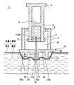
図1は、本発明の第1の実施形態に係るプレフィルドシリンジの概略断面構成図である。また、図2及び図3は、使用時におけるプレフィルドシリンジの概略断面構成図である。<1. First Embodiment: Prefilled Syringe>
[1-1 Configuration]
FIG. 1 is a schematic cross-sectional configuration diagram of a prefilled syringe according to the first embodiment of the present invention. Moreover, FIG.2 and FIG.3 is a schematic cross-section block diagram of the prefilled syringe at the time of use.
図1に示すように、本実施形態例のプレフィルドシリンジ1は、外筒2と、外筒2の中心軸に沿って移動可能とされた薬液容器3と、薬液容器3を移動操作する押圧部4と、両頭針10と、両頭針10を支持する針支持部15とを有して構成されている。また、未使用の状態において薬液容器3を外筒2の基端側に保持するための保持部8と、保持部8と薬液容器3との間を封止するシール部材9と、未使用の状態において無菌状態を保持するための保護部材(キャップ)19を有して構成されている。 As shown in FIG. 1, the
外筒2は、基端と先端を有する筒状とされ、本実施形態例では円筒状の部材で構成されている。なお、以下の説明では、外筒2の一端側を「基端」、他端側を「先端」として説明を行う。 The
外筒2の構成材料としては、例えば、ポリ塩化ビニル、ポリエチレン、ポリプロピレン、環状ポリオレフィン、ポリスチレン、ポリ−(4−メチルペンテン−1)、ポリカーボネート、アクリル樹脂、アクリルニトリル−ブタジエン−スチレン共重合体、ポリエチレンテレフタレート等のポリエステル、ブタジエン−スチレン共重合体、ポリアミド(例えば、ナイロン6、ナイロン6・6、ナイロン6・10、ナイロン12)のような各種樹脂が挙げられる。その中でも、成形が容易であるという点で、ポリプロピレン、環状ポリオレフィン、ポリエステル、ポリ−(4−メチルペンテン−1)のような樹脂を用いることが好ましい。なお、外筒2の構成材料は、内部の視認性を確保するために、実質的に透明であることが好ましい。 As a constituent material of the
薬液容器3は、先端と基端とを有する筒状であって、内部に底部5を有し先端側に先端開口部3aを有する有底筒状の部材で構成されている。この薬液容器3は、未使用の状態において、外筒2の基端側に保持されている。また、薬液容器3の外径は、外筒2の内径よりも小さくされており、使用時において、薬液容器3が外筒2内部を移動する際に、外筒2の内周面と薬液容器3の外周面とがほぼ非接触状態となる大きさとされている。 The chemical
薬液容器3の構成材料としては、特に限定されないが、例えば、上述した外筒2の構成材料と同様のものを用いることができる。なお、薬液容器3の構成材料は、内部の視認性を確保できるために、実質的に透明であることが好ましい。また、薬液容器3の外周面には、図示しない目盛りが形成されている。これにより、薬液容器3内部に収納されている薬液の量を把握することができる。 Although it does not specifically limit as a constituent material of the chemical |
そして、薬液容器3内部の先端側には、先端開口部3aを封止する封止体6が気密に保持されている。封止体6は、薬液容器3の内周面に沿って移動可能に設けられており、後述する両頭針10の基端側の第2の針先11が疎通できるように構成されている。 And the sealing
薬液容器3の先端開口部3aに設けられた封止体6の構成材料としては、特に限定されないが、薬液容器3との液密性を良好にするために弾性材料で構成することが好ましく、例えば、天然ゴム、ブチルゴム、イソプレンゴム、イソブチレンゴム、ブタジエンゴム、スチレン−ブタジエンゴム、シリコーンゴムのような各種ゴム材料や、ポリウレタン系、ポリエステル系、ポリアミド系、オレフィン系、スチレン系等の各種熱可塑性エラストマー、あるいはそれらの混合物等の弾性材料を用いることができる。 The constituent material of the sealing
なお、封止体6は、少なくともその外周部が前述のように弾性材料で構成されていればよく、例えば、樹脂材料で構成された芯部(図示せず)を有し、この芯部の外周を覆うように上述した弾性材料が配置された構成のものでもよい。 In addition, the sealing
そして、薬液容器3の底部5と封止体6とで囲まれる薬液容器3内部の空間7には、予め薬液Mが液密(気密)に収納されている。この空間7は、封止体6により気密的に封止された密封空間であり、無菌状態が維持されている。 And the chemical | medical solution M is beforehand liquid-tightly accommodated in the
薬液容器3の空間7に収納される薬液Mとしては、本実施形態例では、例えばインフルエンザ等の各種の感染症を予防する各種のワクチンが挙げられるが、ワクチンに限定されるものではない。なお、ワクチン以外では、例えば、ブドウ糖等の糖質注射液、塩化ナトリウムや乳酸カリウム等の電解質補正用注射液、ビタミン剤、抗生物質注射液、造影剤、ステロイド剤、蛋白質分解酵素阻害剤、脂肪乳剤、抗癌剤、麻酔薬、覚せい剤、麻薬、ヘパリンカルシウム、抗体医薬等が挙げられる。 Examples of the chemical solution M stored in the
また、空間7に収納される薬液Mの量(空間7の体積)は、特に限定されないが、例えば、0.02〜2.0mL程度が好ましく、0.05〜0.8mL程度がより好ましい。すなわち、プレフィルドシリンジ1は、特に、このような少量の薬液を投与する場合に好適なものである。 Moreover, although the quantity (volume of the space 7) of the chemical | medical solution M accommodated in the
保持部8は、外筒2の内周面と薬液容器3との外周面との間に配置され、外筒2の内周面に固定して設けられるものであり、本実施形態例では、外筒2基端の内周面に鍔状に形成されている。上述したように、本実施形態例の薬液容器3は、使用時において、薬液容器3が外筒2内部を移動する際に、外筒2の内周面と薬液容器3の外周面とがほぼ非接触状態となる大きさとされている。このため、外筒2の内周面と薬液容器3の外周面との間には、所定の距離の間隙ができており、この間隙が保持部8により縮小されている。 The holding
本実施形態例では、外筒2、保持部8は一体に形成されている。保持部8の構成材料としては、上述した外筒2の構成材料と同様のものを用いることができる。 In this embodiment, the
シール部材9は、未使用の状態において、保持部8と薬液容器3との間を封止すると共に、薬液容器3を外筒2の基端側に保持するために設けられるものであり、保持部8に対向する薬液容器3先端の外周面に全周にわたって固定されている。シール部材9の構成材料としては、特に限定されないが、底部5の構成材料と同様のものを用いることができ、本実施形態例では、オーリング状の弾性部材で構成されている。また、シール部材9は、二色成形で形成しても良い。 The
外筒2に形成された鍔状の保持部8の側面にシール部材9の外筒2側の端部が密着することにより、保持部8で縮小された外筒2の内周面と薬液容器3の外周面との間の間隙が完全に封止される。そして、未使用の状態(初期状態)において、薬液容器3は、保持部8とシール部材9によって外筒2の基端側に保持されている。 The inner peripheral surface of the
このように、シール部材9が、外筒2に形成された保持部8と薬液容器3との間に設けられることにより、薬液容器3の先端が外筒2の基端側に安定して保持され、また、外筒2の内周面と、薬液容器3で囲まれる領域(外筒内空間41)が気密的に封止されている。 As described above, the
本実施形態例では、シール部材9を薬液容器3の先端側に設けることにより、初期状態において薬液容器3の先端側が外筒2の基端側に保持される構成としたが、初期状態における薬液容器3の位置は、後述する両頭針10の第2の針先11が封止体6に穿刺しない位置であればよい。したがって、シール部材9を設ける位置は薬液容器3の先端部に限定されるものではない。 In this embodiment, the
押圧部4は、円板状に形成されており、薬液容器3の基端面を被覆して薬液容器3と一体に形成されている。本実施形態例では、薬液容器3と押圧部4とは一体に形成されているが、これに限らず、例えば薬液容器3と押圧部24とを別部材で構成し、これらを接着剤により接着又は融着等で接合してもよい。押圧部4を押圧することにより、薬液容器3は外筒2に対して基端側に移動する。 The pressing portion 4 is formed in a disc shape, and is formed integrally with the chemical
両頭針10は、先端側に生体を穿刺可能な鋭利な第1の針先12を有し、基端側に薬液容器3の封止体6に刺通可能な鋭利な第2の針先11を有している。そして、両頭針10の基端側の第2の針先11が封止体6を刺通することにより、その両頭針10の基端側が薬液容器3の内部に連通するように構成されている。 The double-ended
両頭針10としては、ISOの医療用両頭針の基準(ISO9626:1991/Amd.1:2001(E))で22〜33Gのサイズ(外径:0.2〜0.7mm)のものを使用することができる。なお、皮膚上層部への投与に用いる場合は、26〜33Gのものを用いることができ、好ましくは、30〜33Gのサイズのものを使用することができる。 As the double-ended
両頭針10の先端側の第1の針先12には刃面12aを有する刃先が形成されており、その先端側の刃面12aにおける両頭針10の軸方向の長さ(以下、「ベベル長」と言う)Bは、皮膚上層部の最薄の厚さである1.4mm(成人)以下であることが好ましく、また、33Gの両頭針に短ベベルを形成したときのベベル長である約0.5mm以上であることが好ましい。すなわち、ベベル長Bは、0.5〜1.4mmの範囲内に設定されることが好ましい。ここで、皮膚上層部とは、表皮と真皮を指す。 The
さらに、ベベル長Bは、皮膚上層部の最薄の厚さである0.9mm(小児)以下であることがより好ましい。すなわち、ベベル長Bは、0.5〜0.9mmの範囲内に設定されることがより好ましい。 Furthermore, the bevel length B is more preferably 0.9 mm (child) or less, which is the thinnest thickness of the upper skin layer. That is, the bevel length B is more preferably set within the range of 0.5 to 0.9 mm.
両頭針10の構成材料としては、特に限定されないが、例えば、ステンレス鋼、アルミニウムまたはアルミニウム合金、チタンまたはチタン合金、Ni−Ti合金等の超弾性合金等の各種金属材料、ポリフェニレンサルファイド等の各種硬質樹脂材料等が挙げられる。 The constituent material of the double-ended
針支持部15は、略円板状の針支持部本体20と、調整部17と、安定部13と、押圧目安部であるガイド部16とを備えている。この針支持部15は、両頭針10を保持した状態で外筒2の先端側の開口を閉じるように配置される。このとき、針支持部15を貫通する両頭針10の第2の針先11は、外筒2内の、針支持部15と薬液容器3によって囲まれる外筒内空間41に配置されている。 The
調整部17及び安定部13は、針支持部本体20の先端側に設けられている。この針支持部15の材質としては、特に限定されないが、例えば、上述した外筒2の材質と同様のものを用いることができる。更に、針支持部15は、外筒2と一体に形成してもよい。 The adjusting
また、針支持部本体20には、先端側から基端側へ貫通する第1の通気孔14が設けられている。この第1の通気孔14によって、外筒内空間41と、この外筒内空間41の外側とを連通する。更に、外筒内空間41の無菌状態の維持を高めるために、第1の通気孔14にフィルタを設けてもよい。 Further, the needle support portion
なお、本例では、第1の通気孔14の数を1つ設けた例を説明したが、これに限定されるものではなく、第1の通気孔14を針支持部本体20に複数形成してもよい。 In this example, the example in which the number of the first ventilation holes 14 is one has been described. However, the present invention is not limited to this, and a plurality of the first ventilation holes 14 are formed in the
調整部17は、針支持部本体20の一方の先端面20aの中央部に設けられており、針支持部本体20の軸方向に突出する凸部として構成されている。この調整部17の軸心は、針支持部本体20の軸心に一致している。そして、この調整部17には、両頭針10が貫通している。また、調整部17の端面は、両頭針10の第1の針先12側が突出する針突出面17aになっている。 The
針突出面17aは、両頭針10の軸方向に直交する平面として形成されている。この針突出面17aは、両頭針10を皮膚上層部に穿刺するときに、皮膚の表面に接触して両頭針10を穿刺する深さを規定する。つまり、両頭針10が皮膚上層部に穿刺される深さは、針突出面17aから突出する両頭針10の長さ(以下、「突出長L」という。)によって決定される。 The
皮膚上層部の厚みは、皮膚の表面から真皮層までの深さに相当し、概ね、0.5〜3.0mmの範囲内にある。そのため、両頭針10の突出長Lは、0.5〜3.0mmの範囲に設定することができる。 The thickness of the upper skin layer corresponds to the depth from the skin surface to the dermis layer, and is generally in the range of 0.5 to 3.0 mm. Therefore, the protruding length L of the double-ended
ところで、ワクチンは一般的に上腕部に投与されるが、皮膚上層部への投与の場合、皮膚が厚い肩周辺部、特に三角筋部が好ましいと考えられる。そこで、小児19人と大人31人について、三角筋の皮膚上層部の厚みを測定した。この測定は、超音波測定装置(NP60R−UBM 小動物用高解像度用エコー、ネッパジーン(株))を用いて、超音波反射率の高い皮膚上層部を造影することで行った。なお、測定値が対数正規分布となっていたため、幾何平均によってMEAN±2SDの範囲を求めた。 By the way, the vaccine is generally administered to the upper arm part, but in the case of administration to the upper skin part, it is considered that the shoulder peripheral part where the skin is thick, particularly the deltoid part is preferable. Therefore, the thickness of the upper layer of the deltoid muscle was measured for 19 children and 31 adults. This measurement was performed by imaging the upper layer of the skin with high ultrasonic reflectivity using an ultrasonic measurement device (NP60R-UBM high-resolution echo for small animals, Nepagene). In addition, since the measured value was logarithmic normal distribution, the range of MEAN ± 2SD was obtained by geometric mean.
その結果、小児の三角筋における皮膚上層部の厚みは、0.9〜1.6mmであった。また、成人の三角筋における皮膚上層部の厚みは、遠位部で1.4〜2.6mm、中央部で1.4〜2.5mm、近位部で1.5〜2.5mmであった。以上のことから、三角筋における皮膚上層部の厚みは、小児の場合で0.9mm以上、成人の場合で1.4mm以上であることが確認された。したがって、三角筋の皮膚上層部における注射において、両頭針10の突出長Lは、0.9〜1.4mmの範囲に設定することが好ましい。 As a result, the thickness of the upper skin layer of the deltoid muscle of children was 0.9 to 1.6 mm. In addition, the thickness of the upper skin layer in the deltoid muscles of adults was 1.4 to 2.6 mm at the distal part, 1.4 to 2.5 mm at the central part, and 1.5 to 2.5 mm at the proximal part. It was. From the above, it was confirmed that the thickness of the upper skin layer in the deltoid muscle was 0.9 mm or more in the case of children and 1.4 mm or more in the case of adults. Therefore, in the injection in the upper layer portion of the deltoid muscle, it is preferable that the protruding length L of the double-ended
突出長Lをこのように設定することで、第1の針先12の刃面12aを皮膚上層部に確実に位置させることが可能となる。その結果、刃面12aに開口する針孔(薬液排出口)は、刃面12a内のいかなる位置にあっても、皮膚上層部に位置することが可能である。なお、薬液排出口が皮膚上層部に位置しても、第1の針先12が皮膚上層部に深く刺されば、第1の針先12の端部の側面と切開された皮膚との間から薬液Mが皮下に流れてしまうため、刃面12aが確実に皮膚上層部にあることが重要である。 By setting the protrusion length L in this manner, the
なお、26Gよりも太い両頭針では、ベベル長Bを1.0mm以下にすることは難しい。したがって、両頭針10における第1の針先12の突出長Lを好ましい範囲(0.9〜1.4mm)に設定するには、26Gよりも細い両頭針を使用することが好ましい。 Note that it is difficult to set the bevel length B to 1.0 mm or less with a double-ended needle thicker than 26G. Therefore, in order to set the protruding length L of the
針突出面17aは、周縁から両頭針10の周面までの距離Sが1.4mm以下となるように形成し、好ましくは0.3〜1.4mmの範囲で形成する。この針突出面17aの周縁から両頭針10の周面までの距離Sは、皮膚上層部へ薬液を投与することで形成される水疱に圧力が加わることを考慮して設定している。つまり、針突出面17aは、皮膚上層部に形成される水疱よりも十分に小さく、水疱の形成を妨げない大きさに設定している。その結果、針突出面17aが両頭針10の周囲の皮膚を押圧して、投与された薬液が漏れるということを防止することができる。 The
安定部13は、針支持部本体20の先端面20aに設けられている。この安定部13は、先端面20aの周縁部に連続する筒状に形成されている。この安定部13の筒孔には、両頭針10における第1の針先12及び調整部17が配置されている。つまり、安定部13は、両頭針10が貫通する調整部17の周囲を覆う筒状に形成されている。 The stabilizing
また、図2に示すように、両頭針10の第1の針先12を生体に穿刺すると、針突出面17aが皮膚の表面に接触すると共に安定部13の端面13aも皮膚の表面に接触する。このとき、安定部13の端面13aが皮膚に接触することでプレフィルドシリンジ1が安定し、両頭針10を皮膚に対して略垂直な姿勢に保つことができる。 As shown in FIG. 2, when the
なお、安定部13の端面13aは、針突出面17aと同一平面上に位置させたり、また、針突出面17aよりも両頭針10の第1の針先12側に位置させたりしても、両頭針10を皮膚に対して略垂直な姿勢に保つことができる。なお、安定部13を皮膚に押し付けた際の皮膚の盛り上がりを考慮すると、安定部13の端面13aと針突出面17aにおける軸方向の距離rは、1.3mm以下に設定することが好ましい。 The
また、安定部13の内径dは、皮膚に形成される水疱の直径と同等であるか、それよりも大きい値に設定されている。具体的には、安定部13の内壁面から針突出面17aの周縁までの距離Tが4mm〜15mmの範囲となるように設定されている。これにより、安定部13の内壁面から水疱に圧力が印加されことによって水疱形成が阻害されることを防止することができる。 Further, the inner diameter d of the
安定部13の内壁面から針突出面17aの周縁までの距離Tは、4mm以上であれば、特に上限はない。しかしながら、距離Tを大きくすると、安定部13の外径が大きくなるため、小児のように細い腕に両頭針10を穿刺する場合に、安定部13の端面13a全体を皮膚に接触させることが難しくなる。そのため、距離Tは、小児の腕の細さを考慮して15mmを最大と規定することが好ましい。 The distance T from the inner wall surface of the
また、針突出面17aの周縁から両頭針10の周面までの距離Sが0.3mm以上であれば、調整部17が皮膚に進入することはない。したがって、安定部13の内壁面から針突出面17aの周縁までの距離T(4mm以上)及び針突出面17aの直径(約0.3mm)を考慮すると、安定部13の内径dは9mm以上に設定することができる。 Moreover, if the distance S from the peripheral edge of the
更に、安定部13には、安定部13の外周面から内周面にかけて貫通する第2の通気孔18が形成されている。この第2の通気孔18を安定部13に設けることにより、図2に示すように、安定部13を皮膚に接触させた際に、安定部13と皮膚とで囲まれた空間と、安定部13の外側の空間とを連通させることができる。そして、第1の通気孔14と第2の通気孔18は外筒内空間41を外部に開放する通気手段を構成している。 Furthermore, a
なお、安定部13の形状は、円筒状に限定されるものではなく、例えば、中心に筒孔を有する四角柱や六角柱等の角筒状に形成してもよい。 In addition, the shape of the
ガイド部16は、針支持部本体20の側面部に設けられている。このガイド部16は、針支持部本体20の側面部から針支持部本体20の半径外方向に突出するリング状にフランジとして形成されている。そして、ガイド部16は、安定部13の外周面に対して略垂直に突出している。The
更に、ガイド部16は、皮膚と接触する接触面16aを有している。接触面16aは、安定部13の端面13aと略平行をなす平面である。ガイド部16の接触面16aが皮膚に接触するまで安定部13を押し付けることにより、安定部13及び両頭針10が皮膚を押圧する力を常に所定値以上に確保することができる。これにより、両頭針10の針突出面17aから突出している部分(突出長Lに相当)が確実に皮膚内に穿刺される。 Furthermore, the
そして、ガイド部16の接触面16aから安定部13の端面13aまでの距離は、両頭針10、安定部13及び両頭針10が適正な押圧力で皮膚に穿刺することができるようにその長さが設定されている。以下、この長さを「ガイド部高さy」という。 The distance from the
なお、両頭針10及び安定部13の適正な押圧力は、例えば、3〜20Nである。その結果、使用者に対して両頭針10及び安定部13による皮膚への押圧力をガイド部16で案内することができると共に両頭針10の第1の針先12及び刃面12aを皮膚上層部に確実に位置させることができ、使用者に安心感を与えることができるという効果が得られる。 In addition, the suitable pressing force of the double-ended
具体的には、安定部13の内径dが11〜14mmの範囲の場合、ガイド部高さyは、ガイド部16の突出端面から安定部13の外周面までの長さx(以下、ガイド部長さx)と呼ぶ。)に基づいて、適宜設定される。例えば、安定部13の内径dが12mmの場合、ガイド部高さyは、例えば、ガイド部長さxが3.0mmのとき、2.3〜6.6mmの範囲に設定されている。 Specifically, when the inner diameter d of the
保護部材19は、図2に示すように、両頭針10の生体に穿刺される側の第1の針先12を囲む空間を封止する部材であり、未使用の状態では、針支持部15の安定部13に離脱可能に装着されている。 As shown in FIG. 2, the
この保護部材19は、先端側に底部を有する有底の筒状、本実施形態例では、有底の円筒状に形成されている。未使用の状態において、保護部材19の側面が針支持部15の外周部に装着されることにより、保護部材19内部と、外筒2と針支持部15とシール部材9とで囲まれる外筒内空間41が気密的に封止され、外筒内空間41及び保護部材19内部が密閉される。これにより、外筒内空間41及び保護部材19内部の無菌状態が保持されている。 The
プレフィルドシリンジ1を使用する際は、保護部材19は図1に示すように針支持部15から取り外され、両頭針10の生体に穿刺される側の第1の針先12の封止が解除される。また、このとき、針支持部15の第1の通気孔14により、外筒内空間41も外部に解放される。 When the
保護部材19の構成材料としては、特に限定されないが、例えば、上述した外筒2の構成材料や、封止体6の構成材料と同様のものを用いることができる。 Although it does not specifically limit as a constituent material of the
なお、このプレフィルドシリンジ1では、針支持部15の先端側に保護部材19が装着され、必要な各部が滅菌された後は、前述したように外筒内空間41及び保護部材19内部の無菌状態が保持され、両頭針10の無菌状態が保持される。 In the
[1−2 使用方法]
次に、本実施形態例のプレフィルドシリンジ1の使用方法の一例について説明する。図3に使用時における概略断面構成図を示す。[1-2 Usage]
Next, an example of a method for using the
プレフィルドシリンジ1を使用する際は、まず、用意したプレフィルドシリンジ1の針支持部15先端側から保護部材19を取り外す。これにより、薬液を投与する準備が完了する。このように、このプレフィルドシリンジ1では、容易かつ迅速に、薬液の投与の準備を行うことができる。 When using the
次に、安定部13の端面13aを皮膚に対向させる。これにより、両頭針10の第1の針先12が、穿刺する皮膚に対向される。次に、図2に示すように、プレフィルドシリンジ1を皮膚に対してほぼ垂直に移動させ、両頭針10を皮膚に穿刺すると共に安定部13の端面13aを皮膚に押し付ける。 Next, the
ここで、調整部17の針突出面17aと安定部13の端面13aは、同一平面上に位置している。これにより、調整部17の針突出面17aが皮膚に接触して皮膚を平らに変形させることができ、両頭針10の第1の針先12を突出長Lだけ皮膚に穿刺することができる。 Here, the
次に、ガイド部16の接触面16aが皮膚に接触するまで安定部13を押し付ける。ここで、ガイド部高さyは、両頭針10及び安定部13が適正な押圧力で皮膚に穿刺することができるようにその長さが設定されている。そのため、安定部13によって皮膚を押圧する力が所定の値になる。したがって、使用者に対して安定部13の押圧力を案内することができると共に適正な押圧力で安定部13を皮膚に押し付けることができ、両頭針10の第1の針先12及び刃面12aを確実に皮膚上層部内に位置させることができる。 Next, the
このように、ガイド部16が安定部13の押圧力を案内する目印となることで、両頭針10の第1の針先12を皮膚上層部に確実に位置させることができ、皮膚上層部内に確実に薬液を投与することができると共に、使用者の安心感を向上させることが可能である。 As described above, the
また、安定部13が皮膚と当接することで、両頭針10を安定させて、両頭針10を皮膚に対して真っ直ぐに穿刺することができる。よって、両頭針10に生じるブレを防止することができ、薬液の安定した投与を行うことができる。 In addition, since the stabilizing
更に、例えば0.5mm程度のごく短い突出長の針では、第1の針先12を皮膚に当接させても皮膚に刺さらない場合がある。しかし、安定部13が皮膚に押し付けられて垂直方向に皮膚が押し下げられると、安定部13の内側の皮膚が引っ張られて皮膚に張力が加わった状態となる。そのため、両頭針10の第1の針先12に対して皮膚が逃げ難くなるので、安定部13は、皮膚に第1の針先12がより刺さり易くなるという効果も有している。 Furthermore, for example, with a very short protruding length of about 0.5 mm, even if the
また、突出長Lが0.5〜3.0mmの範囲に設定されているため、両頭針10の第1の針先12及び刃面12aは、確実に皮膚上層部内に位置する。調整部17は、両頭針10の周囲に密着して固定されており、両頭針10の調整部17を貫通する部分と調整部17との間には間隙が生じないようになっている。 Moreover, since the protrusion length L is set in the range of 0.5 to 3.0 mm, the
そのため、調整部17の針突出面17aを皮膚に当接させると、両頭針10の周囲の皮膚を平らに変形させることができる。その結果、両頭針10を突出長Lだけ皮膚に穿刺させることができ、両頭針10の第1の針先12を皮膚上層部内に確実に位置させることができる。 Therefore, when the
次に、押圧部4に指を当て先端方向に押圧することにより薬液容器3を移動操作する。これにより、シール部材9によって保持部8に保持されていた薬液容器3がシール部材9と共に保持部8から外れ、保持部8による薬液容器3の保持が解除される。そして、薬液容器3は、外筒2内部を外筒2にほぼ非接触の状態で先端側に移動する。その後、外筒2内を中心軸に沿って先端側に移動した薬液容器3の封止体6に、図2に示すように、両頭針10の基端側の第2の針先11が刺通し、薬液容器3の内部に連通する。これにより、両頭針10への通液が完了する。 Next, the
押圧部4を押圧する前の薬液容器3は、シール部材9の弾性力により保持部8に密着保持されているので、押圧部4を所定の力で押圧するだけで薬液容器3が保持部8から外れる。また、外筒2は、薬液容器3が外筒2内部を移動する際に外筒2の内周面と薬液容器3の外周面とがほぼ非接触状態となる大きさとされており、また保持部8で縮小された幅の分だけシール部材9の端面から離れている。このため、薬液容器3がシール部材9と共に保持部8から外れた後は、薬液容器3は外筒2とはほぼ非接触で外筒2内を移動し、薬液の通液が行われる。したがって、薬液容器3の移動時に、外筒2内部をシール部材9が設けられた薬液容器3が摺動することがなく、外筒2の内周面と薬液容器3の外周面との間の抵抗は無い状態とされる。 Since the
そして、通液完了後、さらに押圧部4を先端方向に押圧すると、封止体6が薬液容器3内部において、薬液容器3の移動方向に相対的に摺動移動する。これにより、薬液容器3内の薬液が両頭針10内を通り、先端側の第1の針先12から排出され、目的の部位に薬液が投与される。 When the pressing portion 4 is further pressed in the distal direction after the completion of liquid passing, the sealing
本実施形態例のプレフィルドシリンジ1では、上述したように、通液時において薬液容器3やシール部材9は外筒2の内周面に接触しない、又は、多少接触したとしても薬液容器3の外周面と外筒2の内周面との間の抵抗は低抵抗とされるため、薬液容器3を外筒2内で摺動させる動作がない。このため、薬液容器3の外周面や外筒2の内周面に摺動抵抗低減の為のシリコーンを塗布する必要がない。これにより、従来の薬液容器3を外筒2内部で摺動させる動作を要するシリンジに比較して、シリコーンを塗布する工程を省略することができ、製造工程を減らすことができる。また、外筒2の内周面や、薬液容器3の外周面にシリコーンを塗布する必要がないため、シリコーンが、製造工程における圧入工程や嵌合工程の設備に付着することもない。 In the
ここで、本実施形態例のプレフィルドシリンジ1は、図1に示すように、第1の通気孔14、及び第2の通気孔18が設けられているので、押圧部4を先端方向に移動操作する際、外筒内空間41の空気は第1の通気孔14、及び第2の通気孔18を経て外部に排出される。これにより、外筒内空間41の圧力の上昇を防止することができ、押圧部4の移動操作を容易かつ円滑に行うことができ、また、薬液の投与が終了したあと、押圧部4から手を離したとしてもその押圧部4が基端方向に移動してしまうことを防止することができる。 Here, as shown in FIG. 1, the
また、本実施形態例のプレフィルドシリンジ1によれば、必要量の薬液が収納された薬液容器3を有しているので、薬液の無駄を防止することができ、経済的である。 In addition, according to the
また、予め薬液容器3及び両頭針10が設置されており、未使用の状態で、両頭針10が配置されている外筒内空間41の無菌状態が保持されているので、保護部材19を取り外すだけの操作で、容易かつ迅速に薬液の投与の準備を行うことができる。 Further, since the
また、第1の通気孔14及び第2の通気孔18が設けられているので、プレフィルドシリンジ1の組み立てを容易に行うことができる。すなわち、第1の通気孔14及び第2の通気孔18が設けられていない場合には、外筒内空間41は、密閉されているので、シール部材9が設けられた薬液容器3を外筒2内に挿入する際、外筒内空間41を減圧する工程を必要とするが、本実施形態例のプレフィルドシリンジ1では、そのような減圧工程が不要であり、手間がかからず、迅速に組み立てを行うことができる。 Moreover, since the
本実施形態例では、皮下上層部への薬液投与に使用するプレフィルドシリンジを例にしたが、皮下投与、筋肉投与、血管投与など種々の用途に適用することができる。その場合には、両頭針10の突出長L等を種々の用途に対応させればよく、また、安定部13、調整部17、ガイド部16の構成を省略してもよい。 In the present embodiment, the prefilled syringe used for administering the drug solution to the subcutaneous upper layer is taken as an example, but it can be applied to various applications such as subcutaneous administration, intramuscular administration, and vascular administration. In that case, what is necessary is just to make protrusion length L etc. of the double-ended
ところで、本実施形態例のプレフィルドシリンジ1では、保持部8からシール部材9と共に薬液容器3が外れた後は薬液容器3に対する抵抗が急に無くなるため、薬液容器3が先端側に勢いよく移動し、両頭針10の針先を破損するおそれがある。これを防ぐため、両頭針10の第2の針先11が曲がるのを防止する部材を設けることができる。例えば、第2の針先11の周辺部に、弾性部材などを設け、封止体が第2の針先11に急に当たらないようにすることにより、第2の針先11が破損するのを防ぐことができる。 By the way, in the
[1−3 変形例]
次に、本実施形態例の変形例に係るプレフィルドシリンジについて説明する。図3及び図4は、変形例に係るプレフィルドシリンジ21の概略断面構成図である。図3及び図4において、図1及び図2に対応する部分には同一符号を付し重複説明を省略する。[1-3 Modification]
Next, a prefilled syringe according to a modification of this embodiment will be described. FIG.3 and FIG.4 is a schematic cross-section block diagram of the
変形例のプレフィルドシリンジ21は、第1の実施形態に係るプレフィルドシリンジ1において、針支持部15の基端側に、固定部40が構成された例である。 The modified
固定部40は、針支持部本体20の先端面20aと対向する他方の基端面20bの中央部に設けられている。この固定部40は、針支持部本体20の軸方向に略円柱状に突出する凸部として構成されている。そして、固定部40には、両頭針10が貫通しており、固定部40の端面から両頭針10の第2の針先11が突出している。 The fixing
また、この変形例では、両頭針10の軸心と調整部17及び固定部40の軸心が一致している。しかしながら、固定部40は、両頭針10の軸方向に沿って形成されればよく、両頭針10の軸心と固定部40の軸心を一致させなくてもその目的は達成できるものである。更に、固定部40を略円柱状に形成した例を説明したが、固定部40の形状は、略円柱状に限定されるものではない。固定部40は、封止体6を押圧する形状であればよく、例えば略半円状や、角柱状に形成してもよい。 In this modified example, the axis of the double-ended
この固定部40は、針支持部15で外筒2の一端側の開口を閉じた際に、外筒内空間41に配置されている。 The fixing
変形例のプレフィルドシリンジ21を使用する場合も、第1の実施形態と同様、針支持部15先端側から、保護部材19を取り外す。次に、両頭針10の先端側の第1の針先12を腕などの薬液を投与する部位に刺入すると共に安定部13の端面13aを皮膚に押し付ける。 Also when using the
そして、押圧部4に指を当て、先端方向に押圧し、薬液容器3を移動操作する。これにより、保持部8から薬液容器3に固定されたシール部材9が外れ、薬液容器3が無抵抗状態で外筒2内を先端側に移動する。そして、外筒2内を中心軸に沿って先端側に移動した薬液容器3の封止体6に、両頭針10の基端側の第2の針先11が刺通し、図4に示すように、薬液容器3の内部に連通する共に、固定部40が封止体6に当接する。 And a finger | toe is applied to the press part 4 and it presses to a front-end | tip direction, and the chemical |
変形例のプレフィルドシリンジ21では、通液完了後、押圧部4を更に押圧することにより、固定部40に当接された状態の封止体6が薬液容器3内周面を摺動移動し、薬液容器3の基端側に移動する。これにより、薬液容器3内の薬液は両頭針10の第1の針先12から排出され、生体に投与される。 In the
変形例では、固定部40が形成されることにより、封止体6が安定して薬液容器3内を摺動移動する。これにより、薬液の排出が安定する。その他、第1の実施形態と同様の効果を得ることができる。 In the modified example, the fixing
〈2.第2の実施形態:プレフィルドシリンジ〉
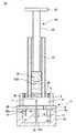
次に、本発明の第2の実施形態に係るプレフィルドシリンジについて説明する。図5は、本実施形態例のプレフィルドシリンジ22の概略断面構成図である。また、図6及び図7は、使用時におけるプレフィルドシリンジ22の概略断面構成図である。図5〜図7において、図1、図2に対応する部分には、同一符号を付し重複説明を省略する。<2. Second Embodiment: Prefilled Syringe>
Next, a prefilled syringe according to a second embodiment of the present invention will be described. FIG. 5 is a schematic cross-sectional configuration diagram of the
[2−1 構成]
薬液容器27は、筒状とされ、本実施形態例では円筒状の部材で構成されており、未使用状態において、外筒2の基端側に保持され、外筒2の基端側に設けられた薬液容器収納部26内に収納されている。また、薬液容器27の外周の径は外筒2の内周の径よりも小さくされており、使用時において、薬液容器27が外筒2内部を移動する際に、外筒2の内周面と薬液容器27の外周面とがほぼ非接触状態となる大きさとされている。[2-1 Configuration]
The
薬液容器27の構成材料としては、特に限定されないが、例えば、上述した外筒2の構成材料と同様のものを用いることができる。なお、薬液容器27の構成材料は、内部の視認性を確保できるために、実質的に透明であることが好ましい。また、薬液容器27の外周面には、図示しない目盛りが形成されている。これにより、薬液容器27内部に収納されている薬液の量を把握することができる。 Although it does not specifically limit as a constituent material of the chemical |
薬液容器27内部には、薬液容器27内部の空間を密封する第1の封止体28及び第2の封止体29が形成されている。第1の封止体28は、薬液容器27内部の先端側に設けられ、両頭針10の第2の針先11が穿刺可能に形成されており、薬液容器27内部に固定して設けられている。一方、第2の封止体29は、薬液容器27内部の基端側に設けられ、薬液容器27内部を摺動可能に形成されている。薬液容器27内部の第1の封止体28、及び第2の封止体29で囲まれる空間7には、薬液Mが液密に保持されている。 A
第1の封止体28、及び第2の封止体29の構成材料は、特に限定されないが、第1の実施形態の封止体6の構成材料と同様のものを用いることができる。 Although the constituent material of the
薬液容器収納部26は、鍔状に形成された保持部8上部に、外筒2の内径よりも小さい外径を有し、未使用状態において内部に薬液容器27を収納できる円筒状の部材で構成されている。この薬液容器収納部26は、未使用の状態において、薬液容器27を外筒2基端側に安定して保持するためのものであり、また、後述する押圧部24を移動操作(押圧)する際には押圧部24のガイドとなるので、その移動操作を容易に行うことができる。 The chemical
本実施形態例では、外筒2、保持部8、薬液容器収納部26は一体に形成されている。これらの保持部8、及び薬液容器収納部26の構成材料としては、上述した外筒2の構成材料と同様のものを用いることができる。 In the present embodiment, the
シール部材9は、未使用の状態において、保持部8と薬液容器27との間を封止すると共に、薬液容器27を外筒2の基端側に保持するために設けられるものであり、保持部8に対向する薬液容器27先端の外周面に全周にわたって固定されている。シール部材9の構成材料としては、特に限定されないが、第1の封止体28及び第2の封止体29の構成材料と同様のものを用いることができ、本実施形態例では、オーリング状の弾性部材で構成されている。 The
外筒2に形成された鍔状の保持部8の側面にシール部材9の外筒2側の端部が密着することにより、保持部8で縮小された外筒2の内周面と薬液容器27の外周面との間の間隙が完全に封止される。そして、未使用の状態において、薬液容器27は、保持部8とシール部材9によって外筒2の基端側に保持されている。 The inner peripheral surface of the
このように、シール部材9が、外筒2に形成された保持部8と薬液容器27との間に設けられることにより、薬液容器27の先端が外筒2の基端側に安定して保持され、また、外筒2の内周面と、薬液容器27で囲まれる領域が気密的に封止されている。 As described above, the
本実施形態例では、シール部材9を薬液容器27の先端側に設けることにより、未使用時において薬液容器27の先端側が外筒2の基端側に保持される構成としたが、未使用時における薬液容器27の位置は、後述する両頭針10の第2の針先11が第1の封止体28に穿刺しない位置であればよい。したがって、シール部材9を設ける位置は薬液容器27の先端部に限定されるものではない。 In this embodiment, the
押圧部24は、押断面が例えば十文字状、又は円形状をなし、先端が第2の封止体29に固定された棒状の本体部25と、本体部25の基端側に設けられた円盤状のフランジ32とから構成されている。すなわち、押圧部24は、薬液容器27に接続され、その薬液容器27の基端に設けられている。本体部25に第2の封止体29を固定する方法は、特に限定されず、例えば、本体部25に雄ネジを形成し、第2の封止体29にその雄ネジに螺合する雌ネジを形成し、その両者を螺合させる方法等が挙げられる。 The
押圧部24の構成材料としては、特に限定されないが、例えば、上述した外筒2の構成材料と同じものを用いることができる Although it does not specifically limit as a constituent material of the
[2−2 使用方法]
本実施形態例のプレフィルドシリンジ22を使用する場合も、第1の実施形態と同様、針支持部15先端側から、保護部材19を取り外す。次に、両頭針10の先端側の第1の針先12を腕などの薬液を投与する部位に刺入すると共に安定部13の端面13aを皮膚に押し付ける。[2-2 Usage]
Also when using the
そして、押圧部24のフランジ32に指を当て、押圧部24を先端方向に押圧し、薬液容器27を移動操作する。これにより、保持部8から薬液容器3に形成されたシール部材9が外れ、薬液容器27が無抵抗状態で外筒2内を先端側に移動する。そして、外筒2内を中心軸に沿って先端側に移動した薬液容器27の第1の封止体28に、両頭針10の基端側の第2の針先11が刺通し、図6に示すように、薬液容器27の内部に連通する。これにより、両頭針10への通液が完了する。 And a finger | toe is applied to the
その後、押圧部24を更に先端方向に押圧することにより、第2の封止体29を第1の封止体28側に摺動移動させ、薬液を排出する。これにより、薬液の投与が行われる。 Thereafter, by further pressing the
本実施形態例のプレフィルドシリンジ22では、薬液容器27と一体に形成されたシール部材9が保持部8から外れれば、薬液容器27とシール部材9は密着しないため薬液容器27は、外筒2内部をほぼ非接触の状態で移動できる。このため、薬液容器27及び外筒2との間にシリコーンを塗布する必要がない。 In the
その他、第1の実施形態と同様の効果を得ることができる。 In addition, the same effects as those of the first embodiment can be obtained.
[2−3 変形例]
次に、上述した第2の実施形態の変形例に係るプレフィルドシリンジについて説明する。図8は、変形例のプレフィルドシリンジ30の未使用の状態を示す概略断面構成図であり、図9は、変形例のプレフィルドシリンジ30の使用時の状態を示す概略断面構成図である。図8及び図9において、図5〜図7に対応する部分には同一符号を付し重複説明を省略する。[2-3 Modification]
Next, the prefilled syringe which concerns on the modification of 2nd Embodiment mentioned above is demonstrated. FIG. 8 is a schematic cross-sectional configuration diagram illustrating an unused state of the modified
変形例に係るプレフィルドシリンジ30は、第2の実施形態に係るプレフィルドシリンジ22において、押圧部24の戻り防止機構を設けた例である。押圧部24の戻り防止機構とは、押圧部24を押圧して投薬が完了した後に、押圧部24が戻って投薬した薬液が漏れないようにするための機構である。 The
変形例では、図8に示すように、押圧部24の戻り防止機構は、薬液容器収納部26の基端面に設けられたストッパ部33と、押圧部24の本体部25の先端側に設けられた係止爪31とで構成されている。 In the modified example, as shown in FIG. 8, the return prevention mechanism of the
ストッパ部33は、中心部に押圧部24の本体部25が挿通される開口部23を有した平板状の部材であり、薬液容器収納部26の基端面に設けられている。ストッパ部33の構成材料は、特に限定されないが、上述した外筒2等と同じ材料を用いることができ、また、ストッパ部33は薬液容器収納部26と一体に形成してもよい。 The
押圧部24の本体部25に設けられた係止爪31は、未使用の状態において、ストッパ部33よりも先端側に位置し、第2の封止体29が押圧部24によって最後まで摺動されたとき、すなわち、薬液投与か終了したときに、ストッパ部33の直下に位置するように設けられている。また、本体部25の係止爪31が形成された部分の直径は、開口部23の直径よりも大きくされており、開口部23は、押圧部24を押圧した場合には係止爪31が挿通し、押圧する力を停止した場合には係止爪31が挿通しない大きさに設計されている。 The locking
以上のような構成のプレフィルドシリンジ30を用いて薬液の投与を行った場合、押圧部24を押し切って、第2の封止体29を最後まで摺動移動させ薬液を全て出し切った状態では、図9に示すように、押圧部24に設けられた係止爪31が、ストッパ部33の先端面に係止する。このため、押圧部24を押し切った後に、押圧部24を押圧する力を抜いたとしても、押圧部24が基端側に戻ることがない。これにより、第2の封止体29が押し切った位置から動かないように固定される。このため、例えば皮膚上層部への投薬時において、皮膚上層部が薬液を排出しようとする力によって押圧部24が押し戻されるのを防ぐことができ、投与した薬液が漏れるのを防止することができる。 In the case where the drug solution is administered using the
〈3.第3の実施形態:プレフィルドシリンジ〉
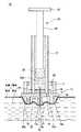
次に、本発明の第3の実施形態に係るプレフィルドシリンジについて説明する。図10は、本実施形態例のプレフィルドシリンジ36の未使用の状態を示す概略断面構成図であり、図11は、使用時の状態を示す概略断面構成図である。図10及び図11において、図5及び図6に対応する部分には同一符号を付し、重複説明を省略する。<3. Third Embodiment: Prefilled Syringe>
Next, a prefilled syringe according to a third embodiment of the present invention will be described. FIG. 10 is a schematic cross-sectional configuration diagram showing an unused state of the
[3−1 構成]
本実施形態例のプレフィルドシリンジ36は、図5における薬液容器収納部26を有しておらず、図10に示すように、薬液容器37は外部に露出した状態とされている。また、薬液容器37の外径は外筒2の内径よりも小さくされており、使用時において、薬液容器37が外筒2内部を移動する際に、外筒2の内周面と薬液容器37の外周面とがほぼ非接触状態となる大きさとされている。さらに、本実施形態例における薬液容器37は、第1の実施形態における薬液容器27よりも軸方向に比較的長く形成され、薬液容器37内の第2の封止体29は、薬液容器37の中央よりも先端側に配置されている。薬液容器37の基端側は、押圧部24を操作する際のガイドとして用いられる。これにより、押圧部24を移動操作する際、第2の封止体29上部の薬液容器37が押圧部24のガイドとなり、その移動操作を容易に行うことができる。[3-1 Configuration]
The
また、本実施形態例では、保持部39は、薬液容器37の基端の外周面に、その外周面と外筒2の内周面との間隙を縮小するように、鍔状に形成されている。この保持部39は、薬液容器37と一体に形成されている。 In the present embodiment, the holding
また、シール部材38は、未使用の状態において、薬液容器37の先端に設けられた保持部39と外筒2との間を封止し、薬液容器37を外筒2基端側に保持するために、保持部39に対向する外筒2基端の内周面にわたって固定されている。 Further, the
薬液容器37形成された鍔状の保持部39の側面にシール部材38が密着することにより、保持部39で縮小された外筒2の内周面と薬液容器37の外周面との間の間隙が完全に封止される。そして、本実施形態例では、薬液容器37は、シール部材38の弾性力によって外筒2の基端側に保持されている。 The
このように、シール部材38が、薬液容器37に形成された保持部39と外筒2との間に設けられることにより、薬液容器37の先端が外筒2の基端側に安定して保持され、また、外筒2の内周面と、薬液容器37で囲まれる領域が気密的に封止されている。そして、本実施形態例においても、未使用の状態において、両頭針10の基端側の第2の針先11に薬液容器37の第1の封止体28が穿刺しない位置に薬液容器37が保持されている。 As described above, the
[3−2 使用方法]
本実施形態例のプレフィルドシリンジ36を使用する場合は、第2の実施形態と同様、針支持部15先端側から、保護部材19を取り外す。次に、両頭針10の先端側の第2の針先11を腕などの薬液を投与する部位に刺入する。そして押圧部24のフランジ32に指を当て、押圧部24を先端方向に押圧、すなわち移動操作する。これにより、シール部材38から薬液容器37に形成された保持部39が外れ、薬液容器37が無抵抗状態で外筒2内を先端側に移動する。そして、外筒2内を中心軸に沿って先端側に移動した薬液容器37の第1の封止体28に、両頭針10の基端側の第2の針先11が刺通し、図11に示すように、薬液容器37の内部に連通する。これにより、両頭針10への通液が完了する。[3-2 Usage]
When using the
その後、第2の実施形態と同様にして、薬液の投与を行う。 Thereafter, the drug solution is administered in the same manner as in the second embodiment.
本実施形態例においても、押圧部24を押圧することで、シール部材38から保持部39、及び保持部39と一体に形成された薬液容器37を容易に先端側に外すことができる。また、外筒2は、薬液容器37が外筒2内部を移動する際に外筒2の内周面と薬液容器37の外周面とがほぼ非接触状態となる大きさとされており、また保持部39で縮小された幅の分だけシール部材38の端面と薬液容器37の外周面は離れている。このため、薬液容器37の保持部39が形成された部位がシール部材38から外れた後は、薬液容器37は外筒2とはほぼ非接触で外筒2内を移動し、薬液の通液が行われる。すなわち、薬液容器37の移動時に、外筒2内部を薬液容器37が摺動することがなく、外筒2の内周面と薬液容器37の外周面との間の抵抗は無い状態とされる。 Also in the present embodiment, by pressing the
このように、本実施形態例のプレフィルドシリンジ36では、薬液容器37と一体に形成された保持部39がシール部材38から外れれば、薬液容器37とシール部材38は密着しないため薬液容器37は、外筒2内部をほぼ非接触の状態で移動できる。このため、薬液容器37及び外筒2との間にシリコーンを塗布する必要がない。 Thus, in the
その他、第1実施形態と同様の効果を得ることができる。 In addition, the same effects as those of the first embodiment can be obtained.
なお、上述の第1の実施形態においても、第2の実施形態に係る変形例の構成を組み合わせることも可能であり、種々の変更が可能である。
以上のように、本発明によれば、外筒内において薬液容器を移動させて用いるプレフィルドシリンジにおいて、外筒の内周面と薬液容器外の周面との間におけるシリコーンレス化を実現することができる。また、予め両頭針及び薬液容器が保持されたプレフィルドシリンジを実現することができる。
したがって、本発明によれば、シリコーンレス化による製造工程の低減が図られ、薬液の無駄を防止でき、容易かつ迅速に薬液の投与の準備を行うことができるプレフィルドシリンジを得ることができる。In addition, also in the above-mentioned 1st Embodiment, it is also possible to combine the structure of the modification based on 2nd Embodiment, and a various change is possible.
As described above, according to the present invention, in the prefilled syringe that is used by moving the chemical liquid container in the outer cylinder, it is possible to realize silicone-less between the inner peripheral surface of the outer cylinder and the peripheral surface outside the chemical liquid container. Can do. Moreover, the prefilled syringe by which the double-ended needle and the chemical | medical solution container were hold | maintained previously is realizable.
Therefore, according to the present invention, it is possible to obtain a prefilled syringe capable of reducing the number of manufacturing steps by eliminating silicone, preventing waste of chemicals, and preparing preparations for administration of chemicals easily and quickly.
1・・・プレフィルドシリンジ、2・・・外筒、3・・・薬液容器、3a・・・先端開口部、4・・・押圧部、5・・・底部、6・・・封止体、7・・・空間、8・・・保持部、9・・・シール部材、10・・・両頭針、11・・・第2の針先、12・・・第1の針先、12a・・・刃面、13・・・安定部、13a・・・端面、14・・・第1の通気孔、15・・・針支持部、16・・・ガイド部、16a・・・接触面、17・・・調整部、17a・・・針突出面、18・・・第2の通気孔、19・・・保護部材、20・・・針支持部本体、21・・・プレフィルドシリンジ、22・・・プレフィルドシリンジ、23・・・開口部、24・・・押圧部、25・・・本体部、26・・・薬液容器収納部、27・・・薬液容器、28・・・第1の封止体、29・・・第2の封止体、30・・・プレフィルドシリンジ、31・・・係止爪、32・・・フランジ、33・・・ストッパ部、34・・・プレフィルドシリンジ、35・・・弾性部材、36・・・プレフィルドシリンジ、37・・・薬液容器、38・・・シール部材、39・・・保持部、40・・・固定部 DESCRIPTION OF
Claims (10)
Translated fromJapanese先端と基端とを有し、前記外筒の内径よりも小さい外径を有する容器であって、先端に先端開口部を有し、前記先端開口部が封止体で封止されることで、容器内部に薬液が密封され、かつ、前記外筒の内部を軸方向に移動可能な薬液容器と、
前記外筒の内周面と前記薬液容器の外周面との間に配置され、前記外筒の内周面、又は前記薬液容器の外周面に固定して設けられた保持部と、
初期状態において、前記保持部と、前記保持部に対向する前記薬液容器の外周面、又は前記外筒の内周面との間を封止すると共に、前記薬液容器を前記外筒の基端側に保持し、前記保持部に対向する前記薬液容器の外周面、又は前記外筒の内周面の円周方向に固定して設けられたシール部材と、
前記薬液容器を移動操作する押圧部と、
一端に生体を穿刺可能な針先を有し、他端に前記封止体に穿刺可能な端部を有する両頭針と、
前記外筒の先端側に設けられ、前記両頭針を支持する針支持部と、を備え、
前記押圧部を先端方向に押圧すると、前記保持部から前記シール部材が外れることにより、初期状態において前記外筒の基端側に保持されていた前記薬液容器の保持が解除され、前記薬液容器が前記外筒に対して先端方向に移動し、前記両頭針の端部が前記封止体を刺通し、前記両頭針の一端に設けられた針先から前記薬液が排出されるように構成されている
プレフィルドシリンジ。An outer cylinder having a distal end and a proximal end;
A container having a distal end and a proximal end and having an outer diameter smaller than an inner diameter of the outer cylinder, the distal end having a distal end opening, and the distal end opening being sealed with a sealing body; The chemical solution is sealed inside the container, and the chemical solution container is movable in the axial direction inside the outer cylinder; and
A holding part disposed between the inner peripheral surface of the outer cylinder and the outer peripheral surface of the chemical liquid container, and fixed to the inner peripheral surface of the outer cylinder or the outer peripheral surface of the chemical liquid container;
In an initial state, the space between the holding portion and the outer peripheral surface of the chemical liquid container facing the holding portion or the inner peripheral surface of the outer cylinder is sealed, and the chemical liquid container is placed on the proximal end side of the outer cylinder And a sealing member provided fixed in the circumferential direction of the outer peripheral surface of the chemical solution container facing the holding portion or the inner peripheral surface of the outer cylinder,
A pressing portion for moving and operating the chemical container;
A double-ended needle having a needle tip capable of puncturing a living body at one end and an end portion capable of puncturing the sealing body at the other end;
A needle support portion provided on the distal end side of the outer cylinder and supporting the double-ended needle;
When the pressing portion is pressed in the distal direction, the sealing member is removed from the holding portion, whereby the holding of the chemical solution container held on the proximal end side of the outer cylinder in the initial state is released, and the chemical solution container is It moves in the distal direction with respect to the outer cylinder, the end of the double-ended needle penetrates the sealing body, and the chemical solution is discharged from the needle tip provided at one end of the double-ended needle. Prefilled syringe.
先端と基端とを有し、前記外筒の内径よりも小さい外径を有する容器であって、容器内部が第1の封止体及び第2の封止体で封止されると共に、前記第1の封止体及び前記第2の封止体で挟まれる容器内部に薬液が密封され、かつ、前記外筒の内部を軸方向に移動可能な薬液容器と、
前記外筒の内周面と前記薬液容器の外周面との間に配置され、前記外筒の内周面、又は前記薬液容器の外周面に固定して設けられた保持部と、
初期状態において、前記保持部と、前記保持部に対向する前記薬液容器の外周面、又は前記外筒の内周面との間を封止すると共に、前記薬液容器を前記外筒の基端側に保持し、前記保持部に対向する前記薬液容器の外周面、又は前記外筒の内周面の円周方向に固定して設けられたシール部材と、
前記薬液容器を移動操作すると共に、前記第2の封止体を前記第1の封止体側に移動操作する押圧部と、
一端に生体を穿刺可能な針先を有し、他端が前記第1の封止体に穿刺可能な端部を有する両頭針と、
前記外筒の先端側に設けられ、前記両頭針を支持する針支持部と、を備え、
前記押圧部を先端方向に押圧すると、前記保持部から前記シール部材が外れることにより、初期状態において前記外筒の基端側に保持されていた前記薬液容器の保持が解除され、前記薬液容器が前記外筒に対して先端方向に移動し、前記両頭針の端部が前記封止体を刺通し、前記両頭針の一端に設けられた針先から前記薬液が排出されるように構成されている
プレフィルドシリンジ。An outer cylinder having a distal end and a proximal end;
A container having a distal end and a proximal end and having an outer diameter smaller than the inner diameter of the outer cylinder, wherein the inside of the container is sealed with a first sealing body and a second sealing body, and A chemical solution sealed inside the container sandwiched between the first sealing body and the second sealing body, and movable in the axial direction inside the outer cylinder; and
A holding part disposed between the inner peripheral surface of the outer cylinder and the outer peripheral surface of the chemical liquid container, and fixed to the inner peripheral surface of the outer cylinder or the outer peripheral surface of the chemical liquid container;
In an initial state, the space between the holding portion and the outer peripheral surface of the chemical liquid container facing the holding portion or the inner peripheral surface of the outer cylinder is sealed, and the chemical liquid container is placed on the proximal end side of the outer cylinder And a sealing member provided fixed in the circumferential direction of the outer peripheral surface of the chemical solution container facing the holding portion or the inner peripheral surface of the outer cylinder,
While operating to move the chemical solution container, a pressing unit for operating to move the second sealing body to the first sealing body side,
A double-ended needle having a needle tip capable of puncturing a living body at one end and an end portion capable of puncturing the first sealing body at the other end;
A needle support portion provided on the distal end side of the outer cylinder and supporting the double-ended needle;
When the pressing portion is pressed in the distal direction, the sealing member is removed from the holding portion, whereby the holding of the chemical solution container held on the proximal end side of the outer cylinder in the initial state is released, and the chemical solution container is It moves in the distal direction with respect to the outer cylinder, the end of the double-ended needle penetrates the sealing body, and the chemical solution is discharged from the needle tip provided at one end of the double-ended needle. Prefilled syringe.
請求項1又は2に記載のプレフィルドシリンジ。The prefilled syringe according to claim 1, further comprising a fixing portion for fixing a position of the sealing body with respect to the double-ended needle in a state where an end portion of the double-ended needle is punctured into the sealing body.
請求項3に記載のプレフィルドシリンジ。The prefilled syringe according to claim 3, wherein the fixing portion is formed along an axial direction of the double-ended needle.
請求項1〜4のいずれか一項に記載のプレフィルドシリンジ。The protective member which seals the space surrounding the needle point which can puncture the living body is detachably attached to the surface side of the needle support part which has the needle point which can puncture the living body. The prefilled syringe as described in any one of these.
請求項1〜5のいずれか一項に記載のプレフィルドシリンジ。The prefilled syringe according to any one of claims 1 to 5, wherein an elastic member is provided around the other end of the double-ended needle.
請求項1〜6のいずれか一項に記載のプレフィルドシリンジ。The prefilled syringe according to any one of claims 1 to 6, wherein the holding portion is provided in a bowl shape on an inner peripheral surface of the outer cylinder.
請求項7に記載のプレフィルドシリンジ。The prefilled syringe according to claim 7, wherein an inner diameter of the holding part is formed larger than an outer diameter of the chemical liquid container, and the chemical liquid container is held by the outer cylinder by the holding part.
請求項1〜6のいずれか一項に記載のプレフィルドシリンジ。The prefilled syringe according to any one of claims 1 to 6, wherein the holding portion is provided in a bowl shape on the outer peripheral surface of the chemical solution container.
請求項9に記載のプレフィルドシリンジ。The prefilled syringe according to claim 9, wherein an outer diameter of the holding part is formed smaller than an inner diameter of the outer cylinder, and the chemical solution container is held by the outer cylinder by the holding part.
Priority Applications (1)
| Application Number | Priority Date | Filing Date | Title |
|---|---|---|---|
| JP2010082582AJP2011212183A (en) | 2010-03-31 | 2010-03-31 | Prefilled syringe |
Applications Claiming Priority (1)
| Application Number | Priority Date | Filing Date | Title |
|---|---|---|---|
| JP2010082582AJP2011212183A (en) | 2010-03-31 | 2010-03-31 | Prefilled syringe |
Publications (1)
| Publication Number | Publication Date |
|---|---|
| JP2011212183Atrue JP2011212183A (en) | 2011-10-27 |
Family
ID=44942582
Family Applications (1)
| Application Number | Title | Priority Date | Filing Date |
|---|---|---|---|
| JP2010082582APendingJP2011212183A (en) | 2010-03-31 | 2010-03-31 | Prefilled syringe |
Country Status (1)
| Country | Link |
|---|---|
| JP (1) | JP2011212183A (en) |
Cited By (5)
| Publication number | Priority date | Publication date | Assignee | Title |
|---|---|---|---|---|
| WO2013046857A1 (en)* | 2011-09-26 | 2013-04-04 | テルモ株式会社 | Protector and syringe assembly |
| WO2020009993A1 (en) | 2018-07-04 | 2020-01-09 | Sutrovax, Inc. | Improvements in immunogenic conjugates |
| JP2022540214A (en)* | 2019-07-12 | 2022-09-14 | 武田薬品工業株式会社 | injection system |
| US11951165B2 (en) | 2016-12-30 | 2024-04-09 | Vaxcyte, Inc. | Conjugated vaccine carrier proteins |
| US11998599B2 (en) | 2016-12-30 | 2024-06-04 | Vaxcyte, Inc. | Polypeptide-antigen conjugates with non-natural amino acids |
Citations (4)
| Publication number | Priority date | Publication date | Assignee | Title |
|---|---|---|---|---|
| JPH03168154A (en)* | 1989-11-29 | 1991-07-19 | Ajinomoto Takara Corp:Kk | Syringe |
| JPH10174717A (en)* | 1996-12-18 | 1998-06-30 | Daikyo Seiko:Kk | Syringe assembly |
| JPH11511358A (en)* | 1995-08-22 | 1999-10-05 | エム ディー シー インベストメント ホールディングス,インコーポレイテッド | Prefilled drug solution injection ampule with retractable injection needle |
| JP2008522751A (en)* | 2004-12-09 | 2008-07-03 | ウェスト ファーマシューティカル サービシズ インコーポレイテッド | Automatic injection and retraction syringe |
- 2010
- 2010-03-31JPJP2010082582Apatent/JP2011212183A/enactivePending
Patent Citations (4)
| Publication number | Priority date | Publication date | Assignee | Title |
|---|---|---|---|---|
| JPH03168154A (en)* | 1989-11-29 | 1991-07-19 | Ajinomoto Takara Corp:Kk | Syringe |
| JPH11511358A (en)* | 1995-08-22 | 1999-10-05 | エム ディー シー インベストメント ホールディングス,インコーポレイテッド | Prefilled drug solution injection ampule with retractable injection needle |
| JPH10174717A (en)* | 1996-12-18 | 1998-06-30 | Daikyo Seiko:Kk | Syringe assembly |
| JP2008522751A (en)* | 2004-12-09 | 2008-07-03 | ウェスト ファーマシューティカル サービシズ インコーポレイテッド | Automatic injection and retraction syringe |
Cited By (6)
| Publication number | Priority date | Publication date | Assignee | Title |
|---|---|---|---|---|
| WO2013046857A1 (en)* | 2011-09-26 | 2013-04-04 | テルモ株式会社 | Protector and syringe assembly |
| US11951165B2 (en) | 2016-12-30 | 2024-04-09 | Vaxcyte, Inc. | Conjugated vaccine carrier proteins |
| US11998599B2 (en) | 2016-12-30 | 2024-06-04 | Vaxcyte, Inc. | Polypeptide-antigen conjugates with non-natural amino acids |
| WO2020009993A1 (en) | 2018-07-04 | 2020-01-09 | Sutrovax, Inc. | Improvements in immunogenic conjugates |
| EP4483896A2 (en) | 2018-07-04 | 2025-01-01 | Vaxcyte, Inc. | Improvements in immunogenic conjugates |
| JP2022540214A (en)* | 2019-07-12 | 2022-09-14 | 武田薬品工業株式会社 | injection system |
Similar Documents
| Publication | Publication Date | Title |
|---|---|---|
| WO2011122395A1 (en) | Prefilled syringe | |
| JP6284595B2 (en) | Injection needle assembly and drug injection device | |
| JP6636503B2 (en) | Injection needle assembly and drug injection device | |
| WO2011125560A1 (en) | Prefilled syringe | |
| WO2011125561A1 (en) | Prefilled syringe and method for assembling prefilled syringe | |
| WO2011122393A1 (en) | Prefilled syringe | |
| WO2011122221A1 (en) | Medicine administration device and medicine injection device | |
| JP5756793B2 (en) | Injection needle assembly and drug injection device | |
| JP2011212182A (en) | Prefilled syringe | |
| WO2016158144A1 (en) | Drug injection device | |
| WO2011068131A1 (en) | Prefilled syringe | |
| JP2011212183A (en) | Prefilled syringe | |
| JP2011115345A (en) | Prefilled syringe | |
| US20180015234A1 (en) | Injection needle assembly and medicine injection apparatus | |
| US20180015232A1 (en) | Injection needle assembly and drug injection device | |
| JP2011212184A (en) | Prefilled syringe | |
| WO2012157318A1 (en) | Injection needle assembly and drug-injecting device | |
| JP2012010970A (en) | Drug injection apparatus | |
| WO2012160852A1 (en) | Injection needle assembly and drug injection device | |
| JP6716541B2 (en) | Injection needle assembly and drug injection device | |
| WO2011125562A1 (en) | Prefilled syringe and method for assembling prefilled syringe | |
| WO2012147415A1 (en) | Injection needle assembly and drug injection device | |
| JPWO2016158145A1 (en) | Injection needle assembly and drug injection device | |
| WO2012160855A1 (en) | Injection needle assembly and drug injection device | |
| JP2016187431A (en) | Injection needle assembly and medicine injection device |
Legal Events
| Date | Code | Title | Description |
|---|---|---|---|
| A621 | Written request for application examination | Free format text:JAPANESE INTERMEDIATE CODE: A621 Effective date:20130214 | |
| A977 | Report on retrieval | Free format text:JAPANESE INTERMEDIATE CODE: A971007 Effective date:20131213 | |
| A131 | Notification of reasons for refusal | Free format text:JAPANESE INTERMEDIATE CODE: A131 Effective date:20131217 | |
| A02 | Decision of refusal | Free format text:JAPANESE INTERMEDIATE CODE: A02 Effective date:20140513 |