JP2011210757A - Processing system and cooling method of transport mechanism - Google Patents
Processing system and cooling method of transport mechanismDownload PDFInfo
- Publication number
- JP2011210757A JP2011210757AJP2010074046AJP2010074046AJP2011210757AJP 2011210757 AJP2011210757 AJP 2011210757AJP 2010074046 AJP2010074046 AJP 2010074046AJP 2010074046 AJP2010074046 AJP 2010074046AJP 2011210757 AJP2011210757 AJP 2011210757A
- Authority
- JP
- Japan
- Prior art keywords
- cooling
- pick
- processing
- processing system
- container
- Prior art date
- Legal status (The legal status is an assumption and is not a legal conclusion. Google has not performed a legal analysis and makes no representation as to the accuracy of the status listed.)
- Pending
Links
- 238000001816coolingMethods0.000titleclaimsabstractdescription251
- 238000012545processingMethods0.000titleclaimsabstractdescription173
- 230000007723transport mechanismEffects0.000titleclaimsabstractdescription69
- 230000007246mechanismEffects0.000claimsabstractdescription78
- 230000032258transportEffects0.000claimsdescription63
- 238000012546transferMethods0.000claimsdescription39
- 238000005452bendingMethods0.000claimsdescription10
- 238000004891communicationMethods0.000claimsdescription2
- 238000013459approachMethods0.000claims2
- 239000004065semiconductorSubstances0.000description59
- 235000012431wafersNutrition0.000description58
- 238000000034methodMethods0.000description21
- 230000008569processEffects0.000description18
- 239000003507refrigerantSubstances0.000description11
- 230000003028elevating effectEffects0.000description8
- 229910000838Al alloyInorganic materials0.000description7
- 229910052782aluminiumInorganic materials0.000description7
- XAGFODPZIPBFFR-UHFFFAOYSA-NaluminiumChemical compound[Al]XAGFODPZIPBFFR-UHFFFAOYSA-N0.000description7
- 239000000758substrateSubstances0.000description7
- 239000007789gasSubstances0.000description6
- 238000012986modificationMethods0.000description6
- 230000004048modificationEffects0.000description6
- 238000010586diagramMethods0.000description5
- 238000011156evaluationMethods0.000description5
- 230000000694effectsEffects0.000description4
- 238000002474experimental methodMethods0.000description4
- 238000010438heat treatmentMethods0.000description4
- 239000010935stainless steelSubstances0.000description4
- 229910001220stainless steelInorganic materials0.000description4
- 238000005530etchingMethods0.000description3
- 239000000463materialSubstances0.000description3
- 238000005192partitionMethods0.000description3
- 238000004088simulationMethods0.000description3
- XUIMIQQOPSSXEZ-UHFFFAOYSA-NSiliconChemical compound[Si]XUIMIQQOPSSXEZ-UHFFFAOYSA-N0.000description2
- 230000015572biosynthetic processEffects0.000description2
- 230000008859changeEffects0.000description2
- 238000009792diffusion processMethods0.000description2
- 239000011521glassSubstances0.000description2
- 238000003780insertionMethods0.000description2
- 230000037431insertionEffects0.000description2
- 229910052751metalInorganic materials0.000description2
- 239000002184metalSubstances0.000description2
- 230000002093peripheral effectEffects0.000description2
- 229910052710siliconInorganic materials0.000description2
- 239000010703siliconSubstances0.000description2
- HBMJWWWQQXIZIP-UHFFFAOYSA-Nsilicon carbideChemical compound[Si+]#[C-]HBMJWWWQQXIZIP-UHFFFAOYSA-N0.000description2
- 229910010271silicon carbideInorganic materials0.000description2
- 229910002601GaNInorganic materials0.000description1
- 229910001218Gallium arsenideInorganic materials0.000description1
- PNEYBMLMFCGWSK-UHFFFAOYSA-Naluminium oxideInorganic materials[O-2].[O-2].[O-2].[Al+3].[Al+3]PNEYBMLMFCGWSK-UHFFFAOYSA-N0.000description1
- 238000000137annealingMethods0.000description1
- 239000000919ceramicSubstances0.000description1
- 229910010293ceramic materialInorganic materials0.000description1
- 230000000052comparative effectEffects0.000description1
- 150000001875compoundsChemical class0.000description1
- 239000000498cooling waterSubstances0.000description1
- PMHQVHHXPFUNSP-UHFFFAOYSA-Mcopper(1+);methylsulfanylmethane;bromideChemical compoundBr[Cu].CSCPMHQVHHXPFUNSP-UHFFFAOYSA-M0.000description1
- 230000002950deficientEffects0.000description1
- 230000006870functionEffects0.000description1
- 239000011261inert gasSubstances0.000description1
- 238000004519manufacturing processMethods0.000description1
- 229910003465moissaniteInorganic materials0.000description1
- 230000003647oxidationEffects0.000description1
- 238000007254oxidation reactionMethods0.000description1
- 230000001590oxidative effectEffects0.000description1
- 238000002360preparation methodMethods0.000description1
- 230000005855radiationEffects0.000description1
- 229920006395saturated elastomerPolymers0.000description1
- 238000003860storageMethods0.000description1
Images


Landscapes
- Container, Conveyance, Adherence, Positioning, Of Wafer (AREA)
Abstract
Description
Translated fromJapanese本発明は、板状の半導体ウエハ等の被処理体を処理する処理システム及び搬送機構の冷却方法に関する。 The present invention relates to a processing system for processing an object to be processed such as a plate-shaped semiconductor wafer and a cooling method for a transfer mechanism.
一般に、半導体デバイス等を製造するためには、板状の半導体ウエハやガラス基板等の被処理体に対して、成膜処理、エッチング処理、酸化拡散処理、改質処理等の各種の処理を繰り返し施す必要がある。例えば枚葉式の処理装置で複数種類の処理を施す場合には、内部に搬送機構を備えた共通搬送室の周囲に、複数の処理装置をゲートバルブを介して連結している(例えば特許文献1)。そして、上記共通搬送室内の搬送機構を用いて、半導体ウエハを上記各処理装置に向けて順に搬送して半導体ウエハに対して順次所望の処理を施すようになっている。 In general, in order to manufacture a semiconductor device or the like, various processes such as a film formation process, an etching process, an oxidative diffusion process, and a modification process are repeatedly performed on an object to be processed such as a plate-shaped semiconductor wafer or a glass substrate. It is necessary to apply. For example, when a plurality of types of processing are performed by a single-wafer processing apparatus, a plurality of processing apparatuses are connected via a gate valve around a common transfer chamber provided with a transfer mechanism inside (for example, Patent Documents). 1). Then, using the transfer mechanism in the common transfer chamber, the semiconductor wafers are sequentially transferred toward the respective processing apparatuses to sequentially perform desired processing on the semiconductor wafers.
ここで従来の搬送機構により処理装置に対して半導体ウエハを搬送する時の状況について説明する。図10は従来の搬送装置と処理装置との位置関係を示す概略構成図である。図10に示すように、処理装置2は、真空排気が可能になされた処理容器4を有しており、この処理容器4内には、その上に半導体ウエハWを載置するための載置台6が設けられている。この載置台6には、抵抗加熱ヒータ等よりなる加熱手段8が設けられており、載置される半導体ウエハWを加熱するようになっている。 Here, the situation when the semiconductor wafer is transferred to the processing apparatus by the conventional transfer mechanism will be described. FIG. 10 is a schematic configuration diagram showing a positional relationship between a conventional transport device and a processing device. As shown in FIG. 10, the processing apparatus 2 includes a
上記処理容器4の天井部には、上記載置台6に対向させてシャワーヘッド10が設けられており、処理容器4内へ必要なガスを導入できるようになっている。また処理容器4の側壁には、半導体ウエハWの搬出入口12が設けられており、この搬出入口12には、ゲートバルブGを介して図示しない真空の搬送室が設けられている。そして、この真空の搬送室内に半導体ウエハWを搬出入させる搬送機構14が設けられている。 A
この搬送機構14は、屈伸及び旋回が可能になされたアーム部16と、このアーム部16の先端に連結されたピック部18とによりなっている。そして、このピック部18を含むアーム部16の一部を上記搬出入口12より処理容器4内へ侵入させることにより半導体ウエハWを搬出入させるようになっている。また、ここで半導体ウエハWを載置台6上へ載置させるには、図示しない昇降ピンを昇降させるようになっている。 The
ところで、上述のように半導体ウエハの搬出入に伴って搬送機構14のアーム部16を処理容器4内へ繰り返し侵入させると、加熱手段8の熱によって高温状態になされた載置台6からの輻射熱や高温状態の半導体ウエハWを保持するピック部18からの熱によってアーム部16の先端側がかなりの高温状態、例えばプロセス条件にもよるが300℃以上の高温状態になることは避けられない。このため、アーム部16自体が熱膨張して反りが発生したり、アーム部16内に設けられている旋回のためのタイミングベルトのテンション等も変化したり、更には回転に用いるベアリングも劣化し、アーム部16の搬送精度が低下してしまう、といった問題があった。 By the way, when the
本発明は、以上のような問題点に着目し、これを有効に解決すべく創案されたものである。本発明は、搬送機構自体の過度の昇温を抑制することが可能な処理システム及び搬送機構の冷却方法である。 The present invention has been devised to pay attention to the above problems and to effectively solve them. The present invention is a processing system capable of suppressing an excessive temperature rise of the transport mechanism itself and a cooling method of the transport mechanism.
請求項1に係る発明は、被処理体に処理を施す処理システムにおいて、前記被処理体に対して処理を施す複数の処理装置と、前記複数の処理装置がその周辺に連結された共通搬送容器と、前記共通搬送容器内に設けられて、屈伸及び旋回可能になされると共に先端に前記被処理体を保持するピック部を有して前記被処理体を前記複数の処理装置に対して搬送する搬送機構と、前記共通搬送容器の側壁に冷却用容器を連結させて設けることにより形成された冷却用領域と、前記冷却用領域に設けられて前記ピック部を冷却するためのピック冷却機構と、を備えたことを特徴とする処理システムである。 According to a first aspect of the present invention, there is provided a processing system for processing an object to be processed, a plurality of processing devices for processing the object to be processed, and a common transport container in which the plurality of processing devices are connected to the periphery thereof. And a pick part that is provided in the common transfer container and is capable of bending and stretching and holding the object to be processed at the tip thereof, and conveys the object to be processed to the plurality of processing apparatuses. A cooling mechanism formed by connecting a cooling container to a side wall of the common transfer container, and a pick cooling mechanism provided in the cooling area for cooling the pick portion; A processing system characterized by comprising:
このように、被処理体に処理を施す処理システムにおいて、被処理体に対して処理を施す複数の処理装置と、複数の処理装置がその周辺に連結された共通搬送容器と、共通搬送容器内に設けられて、屈伸及び旋回可能になされると共に先端に被処理体を保持するピック部を有して被処理体を複数の処理装置に対して搬送する搬送機構と、共通搬送容器の側壁に冷却用容器を連結させて設けることにより形成された冷却用領域と、冷却用領域に設けられてピック部を冷却するためのピック冷却機構とを備え、搬送機構の待機時にピック冷却機構によりピック部を冷却させるようにすることにより、搬送機構自体の過度の昇温を抑制することが可能となる。 As described above, in a processing system that performs processing on an object to be processed, a plurality of processing devices that perform processing on the object to be processed, a common transport container having a plurality of processing devices connected to the periphery thereof, and a common transport container Provided on the side wall of the common transport container, and a transport mechanism for transporting the target object to a plurality of processing apparatuses having a pick portion for holding the target object at the tip and capable of bending and stretching and turning. A cooling area formed by connecting cooling containers and a pick cooling mechanism for cooling the pick section provided in the cooling area, and the pick section by the pick cooling mechanism during standby of the transport mechanism By cooling the sheet, it is possible to suppress an excessive temperature rise of the transport mechanism itself.
請求項4に係る発明は、被処理体に処理を施す処理システムにおいて、前記被処理体に対して処理を施す複数の処理装置と、前記複数の処理装置がその周辺に連結された共通搬送容器と、前記共通搬送容器内に設けられて、屈伸及び旋回可能になされると共に先端に前記被処理体を保持するピック部を有して前記被処理体を前記複数の処理装置に対して搬送する搬送機構と、前記共通搬送容器内に設けられた冷却用領域と、前記冷却用領域に設けられて前記ピック部を冷却するためのピック冷却機構と、を備えたことを特徴とする処理システムである。 According to a fourth aspect of the present invention, there is provided a processing system for processing an object to be processed, a plurality of processing devices for processing the object to be processed, and a common transport container in which the plurality of processing devices are connected to the periphery thereof. And a pick part that is provided in the common transfer container and is capable of bending and stretching and holding the object to be processed at the tip thereof, and conveys the object to be processed to the plurality of processing apparatuses. A processing system comprising: a transport mechanism; a cooling region provided in the common transport container; and a pick cooling mechanism provided in the cooling region for cooling the pick unit. is there.
このように、被処理体に処理を施す処理システムにおいて、被処理体に対して処理を施す複数の処理装置と、複数の処理装置がその周辺に連結された共通搬送容器と、共通搬送容器内に設けられて、屈伸及び旋回可能になされると共に先端に被処理体を保持するピック部を有して被処理体を複数の処理装置に対して搬送する搬送機構と、共通搬送容器内に設けられた冷却用領域と、冷却用領域に設けられてピック部を冷却するためのピック冷却機構とを備え、搬送機構の待機時にピック冷却機構によりピック部を冷却させるようにすることにより、搬送機構自体の過度の昇温を抑制することが可能となる。 As described above, in a processing system that performs processing on an object to be processed, a plurality of processing devices that perform processing on the object to be processed, a common transport container having a plurality of processing devices connected to the periphery thereof, and a common transport container Provided in a common transport container and having a pick part that holds the object to be processed at the tip and conveys the object to be processed to a plurality of processing apparatuses. A cooling mechanism provided in the cooling area and a pick cooling mechanism for cooling the pick part, and the pick part is cooled by the pick cooling mechanism during standby of the transport mechanism. It becomes possible to suppress the excessive temperature rise of itself.
請求項12に係る発明は、被処理体に対して処理を施す複数の処理装置と、前記複数の処理装置がその周辺に連結された共通搬送容器と、前記共通搬送容器内に設けられて、屈伸及び旋回可能になされると共に先端に前記被処理体を保持するピック部を有して前記被処理体を前記複数の処理装置に対して搬送する搬送機構とを有する処理システムにおける前記搬送機構の冷却方法において、前記被処理体を保持することにより加熱された前記ピック部を、前記共通搬送容器の側壁に連結した冷却用容器内の冷却用領域に設けられたピック冷却機構により冷却するようにしたことを特徴とする搬送機構の冷却方法である。 The invention according to
このように、被処理体に対して処理を施す複数の処理装置と、複数の処理装置がその周辺に連結された共通搬送容器と、共通搬送容器内に設けられて、屈伸及び旋回可能になされると共に先端に被処理体を保持するピック部を有して被処理体を複数の処理装置に対して搬送する搬送機構とを有する処理システムにおける搬送機構の冷却方法において、被処理体を保持することにより加熱された前記ピック部を、共通搬送容器の側壁に連結した冷却用容器内の冷却用領域に設けられたピック冷却機構により冷却するようにしたので、搬送機構の待機時にピック冷却機構によりピック部を冷却させるようにすることにより、搬送機構自体の過度の昇温を抑制することが可能となる。 As described above, a plurality of processing apparatuses that perform processing on an object to be processed, a common transport container in which a plurality of processing apparatuses are connected to the periphery thereof, and a common transport container are provided so as to be able to bend and stretch and turn. And a method for cooling a transport mechanism in a processing system having a pick unit for holding the target object at the tip and a transport mechanism for transporting the target object to a plurality of processing apparatuses. Since the pick section heated by this is cooled by the pick cooling mechanism provided in the cooling region in the cooling container connected to the side wall of the common transport container, the pick cooling mechanism is used during the standby of the transport mechanism. By cooling the pick section, it is possible to suppress an excessive temperature rise of the transport mechanism itself.
請求項13に係る発明は、被処理体に対して処理を施す複数の処理装置と、前記複数の処理装置がその周辺に連結された共通搬送容器と、前記共通搬送容器内に設けられて、屈伸及び旋回可能になされると共に先端に前記被処理体を保持するピック部を有して前記被処理体を前記複数の処理装置に対して搬送する搬送機構とを有する処理システムにおける前記搬送機構の冷却方法において、前記被処理体を保持することにより加熱された前記ピック部を、前記共通搬送容器内の冷却用領域に設けられたピック冷却機構により冷却するようにしたことを特徴とする搬送機構の冷却方法である。 The invention according to claim 13 is provided in a plurality of processing devices for processing an object to be processed, a common transport container in which the plurality of processing devices are connected to the periphery thereof, and the common transport container. The transfer mechanism in the processing system having a pick part that holds the object to be processed at a distal end and that can be bent and stretched, and that conveys the object to be processed to the plurality of processing apparatuses. In the cooling method, the pick section heated by holding the object to be processed is cooled by a pick cooling mechanism provided in a cooling region in the common transport container. This is a cooling method.
このように、被処理体に対して処理を施す複数の処理装置と、複数の処理装置がその周辺に連結された共通搬送容器と、共通搬送容器内に設けられて、屈伸及び旋回可能になされると共に先端に被処理体を保持するピック部を有して被処理体を複数の処理装置に対して搬送する搬送機構とを有する処理システムにおける搬送機構の冷却方法において、被処理体を保持することにより加熱された前記ピック部を、共通搬送容器内の冷却用領域に設けられたピック冷却機構により冷却するようにしたので、搬送機構の待機時にピック冷却機構によりピック部を冷却させるようにすることにより、搬送機構自体の過度の昇温を抑制することが可能となる。 As described above, a plurality of processing apparatuses that perform processing on an object to be processed, a common transport container in which a plurality of processing apparatuses are connected to the periphery thereof, and a common transport container are provided so as to be able to bend and stretch and turn. And a method for cooling a transport mechanism in a processing system having a pick unit for holding the target object at the tip and a transport mechanism for transporting the target object to a plurality of processing apparatuses. Since the pick section heated by this is cooled by the pick cooling mechanism provided in the cooling region in the common transport container, the pick section is cooled by the pick cooling mechanism during standby of the transport mechanism. Thus, it is possible to suppress an excessive temperature rise of the transport mechanism itself.
本発明に係る処理システム及び搬送機構の冷却方法によれば、次のような優れた作用効果を発揮することができる。
請求項1及びこれを引用する請求項に係る発明によれば、被処理体に処理を施す処理システムにおいて、被処理体に対して処理を施す複数の処理装置と、複数の処理装置がその周辺に連結された共通搬送容器と、共通搬送容器内に設けられて、屈伸及び旋回可能になされると共に先端に被処理体を保持するピック部を有して被処理体を複数の処理装置に対して搬送する搬送機構と、共通搬送容器の側壁に冷却用容器を連結させて設けることにより形成された冷却用領域と、冷却用領域に設けられてピック部を冷却するためのピック冷却機構とを備え、搬送機構の待機時にピック冷却機構によりピック部を冷却させるようにすることにより、搬送機構自体の過度の昇温を抑制することができる。また、搬送機構自体の過度の昇温を抑制することができるので、搬送精度を高く維持できるのみならず、搬送機構に不具合が発生することも抑制することができる。更には、より温度の高い被処理体も搬送することができる。According to the processing system and the cooling method of the transport mechanism according to the present invention, the following excellent effects can be exhibited.
According to a first aspect of the present invention, and a processing system for processing a target object, a plurality of processing devices for processing the target object, and a plurality of processing devices in the periphery A common transport container connected to the plurality of processing apparatuses, and a pick part that is provided in the common transport container and is capable of bending and stretching and holding the target object at the tip thereof. A transport mechanism, a cooling area formed by connecting a cooling container to the side wall of the common transport container, and a pick cooling mechanism provided in the cooling area for cooling the pick section. The pick mechanism is cooled by the pick cooling mechanism during standby of the transport mechanism, thereby suppressing excessive temperature rise of the transport mechanism itself. In addition, since excessive temperature rise of the transport mechanism itself can be suppressed, not only the transport accuracy can be maintained high, but also occurrence of problems in the transport mechanism can be suppressed. Furthermore, a to-be-processed object with higher temperature can also be conveyed.
請求項4及びこれを引用する請求項に係る発明によれば、被処理体に処理を施す処理システムにおいて、被処理体に対して処理を施す複数の処理装置と、複数の処理装置がその周辺に連結された共通搬送容器と、共通搬送容器内に設けられて、屈伸及び旋回可能になされると共に先端に被処理体を保持するピック部を有して被処理体を複数の処理装置に対して搬送する搬送機構と、共通搬送容器内に設けられた冷却用領域と、冷却用領域に設けられてピック部を冷却するためのピック冷却機構とを備え、搬送機構の待機時にピック冷却機構によりピック部を冷却させるようにすることにより、搬送機構自体の過度の昇温を抑制することができる。また、搬送機構自体の過度の昇温を抑制することができるので、搬送精度を高く維持できるのみならず、搬送機構に不具合が発生することも抑制することができる。更には、より温度の高い被処理体も搬送することができる。 According to a fourth aspect of the present invention, a processing system for processing an object to be processed includes a plurality of processing devices for processing the object to be processed, and a plurality of processing devices in the vicinity thereof. A common transport container connected to the plurality of processing apparatuses, and a pick part that is provided in the common transport container and is capable of bending and stretching and holding the target object at the tip thereof. Transport mechanism, a cooling area provided in the common transport container, and a pick cooling mechanism provided in the cooling area for cooling the pick unit. By cooling the pick part, it is possible to suppress an excessive temperature rise of the transport mechanism itself. In addition, since excessive temperature rise of the transport mechanism itself can be suppressed, not only the transport accuracy can be maintained high, but also occurrence of problems in the transport mechanism can be suppressed. Furthermore, a to-be-processed object with higher temperature can also be conveyed.
請求項12及び請求項13に係る発明によれば、被処理体に対して処理を施す複数の処理装置と、複数の処理装置がその周辺に連結された共通搬送容器と、共通搬送容器内に設けられて、屈伸及び旋回可能になされると共に先端に被処理体を保持するピック部を有して被処理体を複数の処理装置に対して搬送する搬送機構とを有する処理システムにおける搬送機構の冷却方法において、被処理体を保持することにより加熱された前記ピック部を、共通搬送容器の側壁に連結した冷却用容器内の冷却用領域に設けられたピック冷却機構により冷却するようにしたので、搬送機構の待機時にピック冷却機構によりピック部を冷却させるようにすることにより、搬送機構自体の過度の昇温を抑制することが可能となる。また、搬送機構自体の過度の昇温を抑制することができるので、搬送精度を高く維持できるのみならず、搬送機構に不具合が発生することも抑制することができる。更には、より温度の高い被処理体も搬送することができる。 According to the invention which concerns on
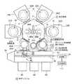
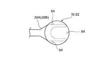
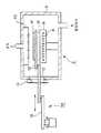
以下に、本発明に係る処理システム及び搬送機構の冷却方法の一実施例を添付図面に基づいて詳述する。図1は本発明に係る処理システムの一例を示す概略平面図、図2は図1に示す処理システムにおける共通搬送容器と冷却用領域の部分を示す概略断面図、図3はピック部で半導体ウエハや冷却プレートを保持している状態を示す平面図である。 Hereinafter, an embodiment of a processing system and a cooling method for a transport mechanism according to the present invention will be described in detail with reference to the accompanying drawings. 1 is a schematic plan view showing an example of a processing system according to the present invention, FIG. 2 is a schematic cross-sectional view showing a portion of a common transfer container and a cooling region in the processing system shown in FIG. 1, and FIG. It is a top view which shows the state holding the cooling plate.
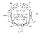
まず、本発明に係る処理システムの一例について説明する。図1及び図2に示すように、この処理システム22は、真空引き可能になされた4つの処理装置24A、24B、24C、24Dを有している。これらの処理装置24A〜24Dとしては、成膜処理やエッチング処理等の真空雰囲気下で行われる全ての処理装置が適用される。特に少なくとも成膜処理やアニール処理等の熱処理を行う処理装置が含まれる。これらの処理装置24A〜24Dは、真空引き可能になされた七角形状の共通搬送容器26の周囲にそれぞれゲートバルブGを介して接続されている。また、この処理システム22は、上記共通搬送容器26内に対して、この真空を破ることなく被処理体としての半導体ウエハWを搬送するためのロードロック室30A、30Bを有しており、両ロードロック室30A、30Bは上記共通搬送容器26にそれぞれゲートバルブGを介して連結されている。上記各ロードロック室30A、30Bは、減圧雰囲気(真空雰囲気)と大気圧雰囲気とに繰り返し実現可能になされている。 First, an example of a processing system according to the present invention will be described. As shown in FIGS. 1 and 2, the processing system 22 includes four
そして、上記各処理装置24A〜24D内には、半導体ウエハWを載置するための載置台32A〜32Dがそれぞれ設けられている。また、上記共通搬送容器26内には、半導体ウエハWを搬送するために屈伸及び旋回可能になされた搬送機構34が設けられ、各処理装置24A〜24D間及びこれらと各ロードロック室30A、30Bとの間で半導体ウエハWを移載できるようになっている。具体的には、この搬送機構34は、上述のように屈伸及び旋回可能になされた2つのアーム部36A、36Bと、これらのアーム部36A、36Bの各先端に設けられたピック部38A、38Bとにより主に構成されており、これらのピック部38A、38B上に半導体ウエハWを直接的に載置保持して、上述のように搬送できるようになっている。図2ではアーム部は1つ記載して他方の記載は省略しているが、実際には図1に示すように2個設けられている。 And in each said
また各ロードロック室30A、30B内には、半導体ウエハWを一時的に保持するためにベース台40A、40Bがそれぞれ設けられている。また上記ロードロック室30A、30Bの反対側には、それぞれゲートバルブGを介して横長のロードモジュール42が取り付けられ、このロードモジュール42の一側には、複数枚の半導体ウエハを収容できるカセット(図示せず)を載置するI/Oポート44が設けられている。そして、このロードモジュール42内には、屈伸及び旋回可能になされた大気側搬送機構46が設けられている。 In addition, base stands 40A and 40B are provided in the
この大気側搬送機構46は、上述のように屈伸及び旋回可能になされた2つのアーム部48と、このアーム部48の先端に設けられた2つのピック部50とにより主に構成されており、これらのピック部50上に半導体ウエハWを直接的に載置保持して搬送できるようになっている。また、この大気側搬送機構46は案内レール52に沿ってその長手方向へ移動可能になされている。そして、このロードモジュール42の一端には、半導体ウエハWの位置合わせ及び方向付けを行うオリエンタ54が設けられており、処理装置24A〜24Dに半導体ウエハWを搬入する前に、ここで半導体ウエハWの位置合わせ及び方向付けを行うようになっている。 The atmosphere-
そして、上記共通搬送容器26は、アルミニウムやアルミニウム合金等により箱状に成形されている。この共通搬送容器26の側壁には、上記各処理装置24A〜24B及び各ロードロック室30A、30Bに対応させて半導体ウエハを搬出入させる搬出入口56が形成されており、ここにゲートバルブGを介して上記各装置が連結されている。 The
この共通搬送容器26には、ガス導入口58及びガス排出口60が設けられており、このガス導入口58を介して不活性ガスとして例えばN2 ガスを導入できるようになっていると共に、上記ガス排出口60より内部雰囲気を真空引きできるようになっている。この共通搬送容器26内は、稼働時には常時真空雰囲気になされている。The
そして、この共通搬送容器26内に設けられる上記搬送機構34は、前述したように、ここでは2つのアーム部36A、36Bと、これらの先端に連結したピック部38A、38Bとを主に有している。 In addition, as described above, the
具体的には、上記各アーム部36A、36Bは、例えば二軸構造の駆動軸62に取り付けられており、上記各アーム部36A、36Bは、その基端部側より第1アーム64、第2アーム66及び第3アーム68を、この順序で相互に屈曲可能に直列に連結してそれぞれ形成されており、水平方向へ向けて伸縮できるようになっている。そして、第3アーム68の先端に上記ピック部38A、38Bが取り付けられている。そして、上記2つのアーム部36A、36Bは交互に選択的に屈伸乃至伸縮できるようになっている。 Specifically, each of the
ここで、上記第1アーム64及び第2アーム66は、アルミニウムやアルミニウム合金等により細長い箱状に成形されており、その中に屈伸動作に必要なプーリやタイミングベルト(図示せず)が設けられている。また第3アーム68は、アルミニウムやアルミニウム合金等により短い板状に形成されており、この先端に上述したように、ピック部38A、38Bが連結されている。上記ピック部38A、38Bは、2股状に成形されており、この材料は、例えばアルミナや窒化アルミやシリコンカーバイトのようなセラミック材よりなる。 Here, the
そして、この七角形状になされた共通搬送容器26の最後の残りの一辺の側壁には、冷却用容器70が連結されている。図1においては、この冷却用容器70は、上記2つのロードロック室30A、30B間に設置されている。この冷却用容器70は、例えばアルミニウムやアルミニウム合金やステンレススチールよりなり、一側が開放された箱状に成型されている。そして、この開放端部に形成されたフランジ部70Aと、共通搬送容器26側のフランジ部26Aとの間にOリング等のシール部材72を介してボルト74により気密に接続固定している。 And the cooling
これにより、上記共通搬送容器26内と冷却用容器70内とは連通状態になされている。そして、この冷却用容器70内は、冷却用領域76として形成されている。そして、この冷却用領域76内には、上記ピック部38A、38Bを冷却するための本発明の特徴とするピック冷却機構78が設けられる。具体的には、上記ピック冷却機構78は、冷却台80と、この冷却台80上に載置されている薄板状の冷却プレート82と、上記冷却プレート82を支持することができる冷却ピン84とにより構成されている。そして、後述するように上記冷却プレート82は上記ピック部38A、38Bにより必要に応じて一時的に保持されて、このピック部38A、38Bを冷却するようになっている。 Thereby, the inside of the
上記冷却台80は、冷却用容器70の底部より支柱86により起立させるようにして支持される。尚、この支柱86を設けないで、冷却台80を冷却用容器70の底部に直接設置するようにしてもよい。この冷却台80は、冷却プレート82の直径と同じか、これよりも僅かに大きく設定されている。この冷却台80には、冷却手段88が設けられており、この冷却台80自体を冷却するようになっている。 The cooling table 80 is supported so as to stand upright from the bottom of the cooling
ここでは、上記冷却手段88として上記冷却台80の略全面に亘って設けられた冷媒流路90を有しており、この冷媒流路90内に冷媒を流すことにより上述したように冷却台80を冷却するようになっている。この冷媒としては、冷却水を用いることができ、この冷媒自体の温度も調整可能になされている。上記冷却台80は、半導体ウエハWに対して汚染のおそれの少ないアルミニウムやアルミニウム合金やステンレススチール等により形成されている。 Here, the cooling means 88 has a
また上記冷却プレート82の大きさは、半導体ウエハWと略同じ直径になされており、またその重量も半導体ウエハWと略同じに設定されている。この冷却プレート82も、上記冷却台80と同じように、半導体ウエハWに対して汚染のおそれの少ないアルミニウムやアルミニウム合金やステンレススチール等により形成されている。 The size of the cooling
そして、上記支持ピン84は、ここではリフタ機構92の一部として形成されている。すなわち、上記冷却プレート82を押し上げ、引き下げるリフタ機構92が設けられている。このリフタ機構92は、3本(図示例では2本のみ記す)の上記支持ピン84を有しており、上記冷却プレート82の周辺部に対応させてその周方向に沿って等間隔で配置されている。図3に支持ピン84とピック部38A、38Bとの上下方向における位置関係を示しており、ピック部38A、38Bの移動時に両者が干渉しないようになっている。 The
上記支持ピン84の下端部は円弧状になされた昇降板94により共通に支持されている。この支持ピン84は熱伝導性が良好な材料、例えばアルミニウムやアルミニウム合金やステンレススチール等により形成されている。そして、この昇降板94は、容器底部を貫通させて設けた昇降ロッド96の上端で支持されると共に、この昇降ロッド96は、アクチュエータ98により昇降可能になされている。また、上記容器底部に対する昇降ロッド96の貫通部には、冷却用容器70内の気密性を維持しつつ上記昇降ロッド96の上下動を許容する金属製のベローズ100が設けられている。 The lower end portions of the support pins 84 are commonly supported by an elevating plate 94 having an arc shape. The
そして、上記冷却台80には、上記支持ピン84を挿通させるためのピン挿通孔102が設けられており、上記ピック部38A、38Bの冷却時に冷却プレート82を上下移動させるために上記支持ピン84を昇降させて、このピン挿通孔102より上方へ出没させることができるようになっている。 The cooling table 80 is provided with a
ここで図1に戻って、この処理システムの全体の動作は、コンピュータよりなるシステム制御部108により、予め作成されたプログラムに基づいて制御されるようになっている。この際、例えばフレキシブルディスク、コンパクトディスク、フラッシュメモリー、ハードディスク等よりなる記憶媒体110に、各構成部の制御を行うための命令を含むプログラムを格納しておき、このプログラムに基づいて所定の条件で処理を行うように各構成部を制御させる。 Here, referring back to FIG. 1, the overall operation of this processing system is controlled by a system control unit 108 comprising a computer based on a program created in advance. At this time, for example, a program including instructions for controlling each component is stored in the
次に、以上のように、処理システム22の動作について説明する。まず、最初に処理システム22における半導体ウエハの概略的な流れについて説明する。I/Oポート44に設置されたカセット容器(図示せず)からは、未処理の半導体ウエハWが大気側搬送機構46によりロードモジュール42内に取り込まれ、この取り込まれた半導体ウエハWはロードモジュール42の一端に設けたオリエンタ54へ搬送されて、ここで位置決め及び方向付けがなされる。上記半導体ウエハWは例えば直径が300mmの板状のシリコン基板よりなる。 Next, the operation of the processing system 22 will be described as described above. First, a schematic flow of a semiconductor wafer in the processing system 22 will be described. From a cassette container (not shown) installed in the I /
位置決め等がなされた半導体ウエハWは、上記大気側搬送機構46により再度搬送され、2つのロードロック室30A、30Bの内のいずれか一方のロードロック室内へ搬入される。このロードロック室内が真空引きされた後に、予め真空引きされた共通搬送容器26内の搬送機構34を用いて、上記ロードロック室内の半導体ウエハWが共通搬送容器26内に取り込まれる。 The semiconductor wafer W that has been positioned is transferred again by the atmosphere-
そして、この共通搬送容器26内へ取り込まれた未処理の半導体ウエハは、搬送機構34によって各処理装置24A〜24Dへ必要に応じて順次搬送され、各処理装置24A〜24D内においてそれぞれ所定の処理が施されることになる。例えば半導体ウエハWに対して、成膜処理やエッチング処理や酸化拡散処理等の熱処理が施されることになる。ここで施された処理の態様によっては半導体ウエハWは例えば300〜900℃程度の高温状態になっている。 The unprocessed semiconductor wafers taken into the
このようにして施すべき各種の処理が全て施されて処理済みとなった半導体ウエハWは、搬送機構34により2つのロードロック室30A、30Bの内のいずれか一方のロードロック室内へ搬入される。そして、このロードロック室内を大気圧復帰し、大気圧復帰後に、このロードロック室内の半導体ウエハWは大気側搬送機構46を用いてロードモジュール42内へ取り込まれ、更に、I/Oポート44の処理済み半導体ウエハ用のカセット容器(図示せず)内へ収容されることになる。そして、以上の動作が繰り返し行われて、半導体ウエハWは連続的に処理される。 The semiconductor wafer W that has been processed after all the various processes to be performed in this way is carried into one of the two
ところで、上述したように半導体ウエハWの処理が繰り返し行われると、搬送機構34のピック部38A、38Bは高温状態の半導体ウエハWを繰り返し保持することになるので、この半導体ウエハWの熱がピック部38A、38Bを伝導してアーム部36A、36Bの全体が昇温される。しかしながら、本発明では、ピック部38A、38Bを冷却するためのピック冷却機構78を設けているので、上記ピック部38A、38B及びアーム部36A、36Bの過度の昇温は抑制されることになり、搬送機構34の搬送精度が低下したり、搬送機構34自体に不具合が生ずることを防止することができる。 By the way, when the processing of the semiconductor wafer W is repeatedly performed as described above, the
すなわち、上述したように半導体ウエハWが連続的に繰り返し処理されているとはいえ、処理態様によっては搬送機構34には、動作を必要としない待機期間が生じることになる。例えば十数秒程度でも待機期間が生じたならば、この待機期間の時にピック部38A、38Bでピック冷却機構78の冷却プレート82を保持するようにして、この冷却プレート82の冷熱でピック部38A、38Bを冷却するようにする。 That is, as described above, although the semiconductor wafer W is repeatedly processed repeatedly, depending on the processing mode, a waiting period during which no operation is required occurs in the
この時のピック部の冷却の方法について図4も参照して説明する。図4は搬送機構のピック部を冷却するための各工程を示す図である。ここでは、一方のピック部38Aを冷却する場合について説明するが、他方のピック部38Bを冷却する場合も同様にして行われる。まず、冷却用容器70内に設けたピック冷却機構78にあっては、冷却台80に設けた冷却手段88の一部である冷媒通路90には冷媒が流されており、この冷却台80を所定の温度、例えば10〜35℃程度に冷却している。そして、この冷却台80上に載置されている冷却プレート82も上記した温度と同じ温度に冷却されている。 A method of cooling the pick section at this time will be described with reference to FIG. FIG. 4 is a diagram illustrating each process for cooling the pick unit of the transport mechanism. Here, the case where one
そして、図4(A)に示すように、搬送機構34の待機期間が訪れたならば、まず、図4(B)に示すように、リフタ機構92の支持ピン84を上昇させることにより、この支持ピン84の上端で冷却台80上の冷却プレート82を突き上げて、これを上方へ押し上げる。次に、図4(C)に示すように、アーム36Aを伸長させることによってこの先端に設けられているピック部38Aを上方へ押し上げられている冷却プレート82の下方へ侵入させる。この際、支持ピン84とピック部38Bとは干渉することはない(図3参照)。 As shown in FIG. 4 (A), if the standby period of the
このように、冷却プレート82の下方にピック部38Aを侵入させたならば、再度、図4(D)に示すように、リフタ機構92を駆動して、今度は支持ピン84を下方へ降下させる。これにより、支持ピン84の上端で支持していた冷却プレート82をピック部38Aに移載し、これに保持させる。これにより、冷却されている冷却プレート82の冷熱によりピック部38Aは冷却されることになる。この冷却プレート82を保持している時間は、長い程冷却効果は高まるが、僅か数秒程度でも十分にピック部38Aを冷却することができる。尚、ここで搬送機構34が上下方向、すなわちZ軸方向へ移動できるような昇降機構を有している場合には、支持ピン84を移動させないでピック部38Aを上方へ移動させて冷却プレート82を保持するようにしてもよい。 Thus, if the
このように、ピック部38Aを冷却したならば、次に、図4(E)に示すように、リフタ機構92を駆動して支持ピン84を再度上昇させる。これにより、ピック部38Aで保持していた冷却プレート82を支持ピン84の上端で突き上げてこれを上方へ押し上げ、これにより、冷却プレート82をピック部38Aから支持ピン84へ移載させる。尚、ここで搬送機構34が上下方向、すなわちZ軸方向へ移動できるような昇降機構を有している場合には、支持ピン84を移動させないでピック部38Aを下方へ移動させて冷却プレート82を支持ピン84に保持させるようにしてもよい。 After the
そして、次に図4(F)に示すように、アーム部36Aを縮退させて冷却プレート82の下方よりピック部38Aを抜き出して退避させる。その後、リフタ機構92を駆動して支持ピン84を降下させて、支持ピン84で支持していた冷却プレート82を冷却台80上に載置させ、この冷却プレート82を冷却台80により、次の冷却操作に備えて冷却しておくことになる。図4(D)に示す冷却時間を例えば3秒程度と仮定すると、図4(A)〜図4(F)に示す各工程を完了するまでの時間は、僅か7秒前後であり、僅かな待機時間が存在すれば、上述したように搬送機構34の冷却を容易に且つ迅速に行うことができる。上述したように他方のアーム部36Bのピック部38Bも上述したと同様に冷却することができる。従って、アーム部36A、36Bも含む搬送機構34の全体を冷却することができる。 Then, as shown in FIG. 4F, the
このように、被処理体に処理を施す処理システムにおいて、被処理体である例えば半導体ウエハWに対して処理を施す複数の処理装置24A〜24Dと、複数の処理装置がその周辺に連結された共通搬送容器26と、共通搬送容器内に設けられて、屈伸及び旋回可能になされると共に先端に被処理体を保持するピック部38A、38Bを有して被処理体を複数の処理装置に対して搬送する搬送機構34と、共通搬送容器の側壁に冷却用容器を連結させて設けることにより形成された冷却用領域76と、冷却用領域に設けられてピック部を冷却するためのピック冷却機構78とを備え、搬送機構の待機時にピック冷却機構によりピック部を冷却させるようにすることにより、搬送機構自体の過度の昇温を抑制することができる。また、搬送機構自体の過度の昇温を抑制することができるので、搬送精度を高く維持できるのみならず、搬送機構に不具合が発生することも抑制することができる。更には、より温度の高い被処理体も搬送することができる。 As described above, in the processing system that performs processing on the target object, a plurality of
<評価実験>
次に、本発明の処理システムについてシミュレーションによって評価実験を行ったので、その評価結果について図5も参照して説明する。図5は本発明の処理システムのシミュレーションによる評価実験の結果を示すグラフであり、ここでは比較例として行われた従来の処理システムの実験結果も併記してある。<Evaluation experiment>
Next, since the evaluation experiment was performed on the processing system of the present invention by simulation, the evaluation result will be described with reference to FIG. FIG. 5 is a graph showing the result of an evaluation experiment by simulation of the processing system of the present invention. Here, the experimental result of a conventional processing system performed as a comparative example is also shown.
図5において、曲線Aは900℃の半導体ウエハを従来の処理システム(冷却なし)で1時間に50枚の割合で搬送した時のピック部の温度変化を示すグラフである。曲線Bは900℃の半導体ウエハを本発明の処理システム(冷却あり)で1時間に100枚の割合で搬送した時のピック部の温度変化を示すグラフであり、曲線Bでは1枚の半導体ウエハを搬送する毎に図4(D)に示すように、ピック部上に冷却プレート82を3秒間保持してピック部の冷却を行うようにしている。この場合、冷媒の温度は25℃に設定している。 In FIG. 5, curve A is a graph showing the temperature change of the pick part when a semiconductor wafer at 900 ° C. is transported at a rate of 50 wafers per hour by a conventional processing system (without cooling). Curve B is a graph showing the temperature change of the pick part when a semiconductor wafer at 900 ° C. is transported at a rate of 100 wafers per hour by the processing system of the present invention (with cooling). Curve B shows one semiconductor wafer. 4D, the cooling
この結果、図5に示すグラフから明らかなように、曲線Aで示すようにピック部の冷却を行っていない従来の処理システムでは高温の半導体ウエハを搬送する毎にピック部の温度は次第に上昇し、1000秒程度経過した頃よりピック部の温度は約400〜440℃程度の範囲内の高い温度で飽和している。これに対して、曲線Bで示すようにピック部の冷却操作で行っている本発明の処理システムでは、従来の処理システムの搬送枚数の2倍の数の半導体ウエハを搬送しているにもかかわらず、ピック部の温度は約70〜110℃程度の範囲内で安定しており、ピック部の温度上昇を大幅に抑制することができることを確認することができた。 As a result, as is apparent from the graph shown in FIG. 5, in the conventional processing system in which the pick section is not cooled as shown by the curve A, the temperature of the pick section gradually increases every time a high-temperature semiconductor wafer is transferred. The temperature of the pick portion has been saturated at a high temperature in the range of about 400 to 440 ° C. after about 1000 seconds. On the other hand, in the processing system of the present invention that is performed by the cooling operation of the pick section as shown by the curve B, the number of semiconductor wafers that is twice as many as that of the conventional processing system is transferred. Therefore, it was confirmed that the temperature of the pick part was stable within a range of about 70 to 110 ° C., and the temperature rise of the pick part could be significantly suppressed.
<第1変形実施例>
次に、本発明の第1変形実施例について図6も参照して説明する。図6は本発明の処理システムの第2変形実施例の搬送機構のピック部を冷却するための各工程を示す図である。尚、図1乃至図4に示す構成部分と同一構成部分については同一参照符号を付して、その説明を省略する。先の図2に示した実施例では、支持ピン84をリフタ機構92の一部として用いることにより昇降可能としたが、これに限定されず、この支持ピン84を冷却手段88によって冷却されている冷却台80上に起立させて固定して設けるようにしてもよい。ここでは、冷却プレート82は熱伝導性の良好な材料よりなる支持ピン84を介して冷却台80の冷熱によって冷却されることになる。そして、この場合には、冷却台80とピック搬送機構34の内の少なくともいずれか一方を上下方向、すなわちZ軸方向へ昇降可能になるように昇降機能を設けておく。<First Modification>
Next, a first modified embodiment of the present invention will be described with reference to FIG. FIG. 6 is a diagram showing each process for cooling the pick portion of the transport mechanism of the second modified embodiment of the processing system of the present invention. The same components as those shown in FIGS. 1 to 4 are denoted by the same reference numerals, and the description thereof is omitted. In the embodiment shown in FIG. 2, the
この場合には、図6(A)に示すように、通常時には冷却プレート82は、冷却台80上に起立させて設けた支持ピン84の上端で支持されている。この状態から図6(B)に示すようにアーム部36Aを伸長させることによってピック部38Aを冷却プレート82の下方へ侵入させる。 In this case, as shown in FIG. 6A, the cooling
次に、図6(C)に示すように、冷却台80を降下させるか、或いはピック部38Aを上昇させて冷却プレート82を支持ピン84からピック部38Aへ移載する。この状態を所定の時間だけ維持することによりピック部38Aを冷却する。そして、所定の時間の冷却が完了したならば、次に図6(D)に示すように、図6(C)の場合とは逆に冷却台80を上昇させるか、或いはピック部38Aを降下させて冷却プレート82をピック部38Aから支持ピン84へ移載する。 Next, as shown in FIG. 6C, the cooling table 80 is lowered or the
次に、図6(E)に示すように、アーム部36Aを縮退させて冷却プレート82の下方よりピック部38Aを抜き出して退避させる。以上のようにしてピック部38Aを冷却することができる。他方のピック部38Bに対しても上述したと同様な工程を経ることによって冷却することができる。この場合にも、先に図2乃至図4を参照して説明した実施例と同様な作用効果を発揮することができる。 Next, as shown in FIG. 6E, the
<第2変形実施例>
次に本発明の第2変形実施例について図7を参照して説明する。図7は本発明の処理システムの第2変形実施例の冷却台の部分を示す断面図である。尚、図1乃至図4に示す構成部分と同一構成部分については同一参照符号を付して、その説明を省略する。また、図7に示されていない部分の構成は、図1乃至図3に示す構成と同様に構成されている。<Second Modification>
Next, a second modified embodiment of the present invention will be described with reference to FIG. FIG. 7 is a cross-sectional view showing a part of a cooling stand of a second modified embodiment of the processing system of the present invention. The same components as those shown in FIGS. 1 to 4 are denoted by the same reference numerals, and the description thereof is omitted. Further, the configuration of the portion not shown in FIG. 7 is the same as the configuration shown in FIGS.
先の各実施例では、主に搬送機構34及び冷却台80は上下方向へは移動しないで共に固定されている場合を例にとって説明したが、これに限定されず、ここでは搬送機構34及び冷却台80の少なくともいずれか一方を上下方向、すなわちZ軸方向へ移動できるように構成しており、且つ冷却プレート82及び支持ピン84(図2乃至図4参照)を共に設けないようにしている。 In each of the previous embodiments, the case where the
ここでは、冷却台80が上下方向へ昇降できるように構成した場合を例にとって説明する。図7に示すように、ここではピック冷却機構78として冷却台80には先の各実施例で用いた冷却プレート82や支持ピン84を設けておらず、これに替えて、上記冷却台80の支柱86に、これを上下移動させる昇降機構120を設けている。具体的には、上記冷却用容器70の底部を区画する底部区画壁70Aに開口122を形成し、この開口122に冷却手段88が設けられた冷却台80を支持する支柱86を貫通させて設けている。 Here, a case where the cooling stand 80 is configured to be able to move up and down in the vertical direction will be described as an example. As shown in FIG. 7, here, the cooling table 80 as the
そして、この支柱86に、上記昇降機構120を構成するアクチュエータ124を設けて上記冷却台80を上下方向(Z軸方向)へ昇降移動できるようにしている。また上記底部区画壁70Aの開口122の周辺部と支柱86との間に伸縮可能になされた金属製のベローズ126が介設されており、冷却用容器70内の気密精を維持しつつ冷却台80の昇降移動を許容できるようになっている。 The
図8は上記本発明の第2変形実施例におけるピック部を冷却するための各工程を示す図である。上述のように構成した第2変形実施例では、図8(A)に示す状態から図8(B)に示すようにアーム部36Aを伸長させることによってピック部38Aを冷却手段88によって冷却されている冷却台80の上方へ位置させる。次に図8(C)に示すように、冷却台80を上昇させることによってこの冷却台80を上記ピック部38Aの下面側に当接させた状態で停止する。この状態を所定の時間だけ維持することにより、冷却台80の上面とピック部38Aの下面とは直接的に接触しているので、ピック部38Aを冷却することができる。そして、所定の時間の冷却が完了したならば、次に図8(D)に示すように、図8(C)の場合とは逆に冷却台80を降下させる。 FIG. 8 is a diagram showing each step for cooling the pick section in the second modified embodiment of the present invention. In the second modified embodiment configured as described above, the
次に図8(E)に示すように、アーム部36Aを縮退させて退避させる。以上のようにしてピック部38Aを冷却することができる。他方のピック部38Bに対しても上述したと同様な工程を経ることによって冷却することができる。この場合にも、先に図2乃至図4を参照して説明した実施例と同様な作用効果を発揮することができる。また、ここで搬送機構34を上下方向へ昇降可能に構成した場合には、図8(C)及び図8(D)に示す各工程の時に、ピック部側を上下方向に昇降させるようにしてピック部の冷却を行うようにしてもよい。 Next, as shown in FIG. 8E, the
更に、図8(C)ではピック部38Aの下面と冷却台80の上面とを直接的に接触させるようにしたが、これに限定されず、両者間に僅かな隙間、例えば1mm以下の隙間が生ずるように接近させた状態とし、ピック部38Aと冷却台80とが直接的に接触させないようにした状態でピック部38Aを冷却するようにしてもよい。このように両者を非接触とした場合には、主として輻射によりピック部38Aを冷却することができる。 Further, in FIG. 8C, the lower surface of the
また、この場合には、ピック部38Aと冷却台80とを非接触としたことから、ピック部38Aの冷却効率は少し減少するが、ピック部38A側が冷却台80より汚染されることを防止することができる。 In this case, since the
尚、以上の各実施例においては、共通搬送容器28の側壁、具体的には2つのロードロック室30A、30B間に冷却用容器70を取り付けて内部に冷却用領域76を形成し、ピック冷却機構78を、この冷却用領域76に位置させて設けるようにしたが、この位置に限定されず、共通搬送容器28の周辺部に他に空きスペースがあるならばその空きスペースにピック冷却機構78を設けるようにしてもよい。 In each of the above embodiments, the cooling
また更に、共通搬送容器70内が広くて、これ自体に空きスペースがある場合には、この空きスペースを冷却用領域76として用い、ここに上述した各実施例に示したようなピック冷却機構78の一部を形成する冷却台80等を設けるようにしてもよい。図9は上述したように、共通搬送容器内の空きスペースに冷却用領域を設けた処理システムの一例を示す部分概略平面図である。尚、先に説明した構成部分と同一構成部分については同一参照符号を付して、その説明を省略している。図9に示すように、ここでは共通搬送容器26の一部の空きスペースに冷却用領域76を設定し、この部分にピック部38A、38Bを冷却する冷却台80等を設けるようにしている。 Furthermore, when the
特に、搬送機構34の各アーム部36A、36Bを共に縮退させた状態で旋回した時の軌跡内に、上記冷却用領域76を設定した場合には、支持ピン84とアーム部36A、36Bとの干渉を避けるために図8に示したような支持ピン84を有していない第2変形実施例のピック冷却機構78を設けるようにする。また上記各実施例では、搬送機構34の待機期間にピック部38A、38Bの冷却操作を行うようにしたが、これに限定されず、定期的に、不定期的に、或いは一定の枚数の半導体ウエハを処理する毎にピック部38A、38Bの冷却操作を行うようにしてもよい。また更に、上記各実施例では冷却手段88として冷却台80に形成した冷媒流路90に冷媒を流すようにしたが、これに限定されず、例えばペルチェ素子等を用いるようにしてもよい。 In particular, when the
また、ここでは被処理体として半導体ウエハを例にとって説明したが、この半導体ウエハにはシリコン基板やGaAs、SiC、GaNなどの化合物半導体基板も含まれ、更にはこれらの基板に限定されず、液晶表示装置に用いるガラス基板やセラミック基板等にも本発明を適用することができる。 Although the semiconductor wafer is described as an example of the object to be processed here, the semiconductor wafer includes a silicon substrate and a compound semiconductor substrate such as GaAs, SiC, GaN, and the like, and is not limited to these substrates. The present invention can also be applied to glass substrates, ceramic substrates, and the like used in display devices.
22 処理システム
24A〜24D 処理装置
26 共通搬送容器
30A,30B ロードロック室
32A〜32D 載置台
34 搬送機構
36A,36B アーム部
38A,38B ピック部
70 冷却用容器
76 冷却用領域
78 ピック冷却機構
80 冷却台
82 冷却プレート
84 支持ピン
88 冷却手段
90 冷媒流路
92 リフタ機構
120 昇降機構
W 半導体ウエハ(被処理体)22
Claims (13)
Translated fromJapanese前記被処理体に対して処理を施す複数の処理装置と、
前記複数の処理装置がその周辺に連結された共通搬送容器と、
前記共通搬送容器内に設けられて、屈伸及び旋回可能になされると共に先端に前記被処理体を保持するピック部を有して前記被処理体を前記複数の処理装置に対して搬送する搬送機構と、
前記共通搬送容器の側壁に冷却用容器を連結させて設けることにより形成された冷却用領域と、
前記冷却用領域に設けられて前記ピック部を冷却するためのピック冷却機構と、
を備えたことを特徴とする処理システム。In a processing system for processing an object to be processed,
A plurality of processing devices for processing the object to be processed;
A common transport container in which the plurality of processing devices are connected to the periphery thereof;
A transport mechanism that is provided in the common transport container and is capable of bending and stretching and having a pick portion that holds the target object at the tip, and transports the target object to the plurality of processing apparatuses. When,
A cooling region formed by connecting a cooling container to the side wall of the common transport container; and
A pick cooling mechanism provided in the cooling region for cooling the pick portion;
A processing system comprising:
前記被処理体に対して処理を施す複数の処理装置と、
前記複数の処理装置がその周辺に連結された共通搬送容器と、
前記共通搬送容器内に設けられて、屈伸及び旋回可能になされると共に先端に前記被処理体を保持するピック部を有して前記被処理体を前記複数の処理装置に対して搬送する搬送機構と、
前記共通搬送容器内に設けられた冷却用領域と、
前記冷却用領域に設けられて前記ピック部を冷却するためのピック冷却機構と、
を備えたことを特徴とする処理システム。In a processing system for processing an object to be processed,
A plurality of processing devices for processing the object to be processed;
A common transport container in which the plurality of processing devices are connected to the periphery thereof;
A transport mechanism that is provided in the common transport container and is capable of bending and stretching and having a pick portion that holds the target object at the tip, and transports the target object to the plurality of processing apparatuses. When,
A cooling area provided in the common transport container;
A pick cooling mechanism provided in the cooling region for cooling the pick portion;
A processing system comprising:
冷却台と、
前記冷却台により冷却されると共に前記ピック部により保持される冷却プレートと、
前記冷却プレートを支持することができる支持ピンと、
を有することを特徴とする請求項1乃至4のいずれか一項に記載の処理システム。The pick cooling mechanism is
A cooling stand;
A cooling plate cooled by the cooling table and held by the pick unit;
A support pin capable of supporting the cooling plate;
The processing system according to claim 1, wherein the processing system includes:
前記複数の処理装置がその周辺に連結された共通搬送容器と、
前記共通搬送容器内に設けられて、屈伸及び旋回可能になされると共に先端に前記被処理体を保持するピック部を有して前記被処理体を前記複数の処理装置に対して搬送する搬送機構とを有する処理システムにおける前記搬送機構の冷却方法において、
前記被処理体を保持することにより加熱された前記ピック部を、前記共通搬送容器の側壁に連結した冷却用容器内の冷却用領域に設けられたピック冷却機構により冷却するようにしたことを特徴とする搬送機構の冷却方法。A plurality of processing devices for processing the object to be processed;
A common transport container in which the plurality of processing devices are connected to the periphery thereof;
A transport mechanism that is provided in the common transport container and is capable of bending and stretching and having a pick portion that holds the target object at the tip, and transports the target object to the plurality of processing apparatuses. In the cooling method of the transport mechanism in a processing system comprising:
The pick section heated by holding the object to be processed is cooled by a pick cooling mechanism provided in a cooling region in a cooling container connected to a side wall of the common transport container. A cooling method for the transport mechanism.
前記複数の処理装置がその周辺に連結された共通搬送容器と、
前記共通搬送容器内に設けられて、屈伸及び旋回可能になされると共に先端に前記被処理体を保持するピック部を有して前記被処理体を前記複数の処理装置に対して搬送する搬送機構とを有する処理システムにおける前記搬送機構の冷却方法において、
前記被処理体を保持することにより加熱された前記ピック部を、前記共通搬送容器内の冷却用領域に設けられたピック冷却機構により冷却するようにしたことを特徴とする搬送機構の冷却方法。A plurality of processing devices for processing the object to be processed;
A common transport container in which the plurality of processing devices are connected to the periphery thereof;
A transport mechanism that is provided in the common transport container and is capable of bending and stretching and having a pick portion that holds the target object at the tip, and transports the target object to the plurality of processing apparatuses. In the cooling method of the transport mechanism in a processing system comprising:
A transport mechanism cooling method, wherein the pick section heated by holding the object to be processed is cooled by a pick cooling mechanism provided in a cooling region in the common transport container.
Priority Applications (1)
| Application Number | Priority Date | Filing Date | Title |
|---|---|---|---|
| JP2010074046AJP2011210757A (en) | 2010-03-29 | 2010-03-29 | Processing system and cooling method of transport mechanism |
Applications Claiming Priority (1)
| Application Number | Priority Date | Filing Date | Title |
|---|---|---|---|
| JP2010074046AJP2011210757A (en) | 2010-03-29 | 2010-03-29 | Processing system and cooling method of transport mechanism |
Publications (1)
| Publication Number | Publication Date |
|---|---|
| JP2011210757Atrue JP2011210757A (en) | 2011-10-20 |
Family
ID=44941547
Family Applications (1)
| Application Number | Title | Priority Date | Filing Date |
|---|---|---|---|
| JP2010074046APendingJP2011210757A (en) | 2010-03-29 | 2010-03-29 | Processing system and cooling method of transport mechanism |
Country Status (1)
| Country | Link |
|---|---|
| JP (1) | JP2011210757A (en) |
- 2010
- 2010-03-29JPJP2010074046Apatent/JP2011210757A/enactivePending
Similar Documents
| Publication | Publication Date | Title |
|---|---|---|
| KR100613171B1 (en) | Semiconductor substrate cooling method and apparatus | |
| US8196619B2 (en) | Load lock apparatus, processing system and substrate processing method | |
| JP4860167B2 (en) | Load lock device, processing system, and processing method | |
| JP5689483B2 (en) | Substrate processing apparatus, substrate support, and method for manufacturing semiconductor device | |
| JP6339057B2 (en) | Substrate processing apparatus, semiconductor device manufacturing method, and program | |
| KR101227809B1 (en) | Method for reducing temperature of substrate placing table, computer-readable storage medium, and substrate processing system | |
| US20120170999A1 (en) | Load lock device and processing system | |
| US10425990B2 (en) | Vacuum processing device | |
| JP3380652B2 (en) | Processing equipment | |
| EP3073512A1 (en) | Substrate treatment device and method | |
| US10115611B2 (en) | Substrate cooling method, substrate transfer method, and load-lock mechanism | |
| KR20140034318A (en) | Method and apparatus for cooling subject to be processed, and computer-readable storage medium | |
| JP2015050418A (en) | Substrate cooling device, substrate cooling method, and substrate processing device | |
| JP2011061149A (en) | Common transport device, and processing system using the same | |
| JP2003037147A (en) | Substrate carrying apparatus and thermally treatment method | |
| US6957690B1 (en) | Apparatus for thermal treatment of substrates | |
| JP2011210757A (en) | Processing system and cooling method of transport mechanism | |
| JP2011204735A (en) | Substrate processing apparatus and manufacturing method of semiconductor device | |
| JP2013201333A (en) | Substrate processing apparatus, manufacturing method of semiconductor device, and substrate processing method | |
| JP2014123655A (en) | Substrate transfer apparatus, method for transferring substrate, and substrate processing system | |
| WO2012043495A1 (en) | Transfer apparatus and processing system | |
| JP2002043388A (en) | Semiconductor manufacturing equipment | |
| JP2005260133A (en) | Substrate processing equipment | |
| JP2012069628A (en) | Substrate-processing apparatus |