JP2011205850A - Noncontact power-receiving apparatus and noncontact charging system - Google Patents
Noncontact power-receiving apparatus and noncontact charging systemDownload PDFInfo
- Publication number
- JP2011205850A JP2011205850AJP2010072990AJP2010072990AJP2011205850AJP 2011205850 AJP2011205850 AJP 2011205850AJP 2010072990 AJP2010072990 AJP 2010072990AJP 2010072990 AJP2010072990 AJP 2010072990AJP 2011205850 AJP2011205850 AJP 2011205850A
- Authority
- JP
- Japan
- Prior art keywords
- control unit
- load
- charge
- charging
- signal
- Prior art date
- Legal status (The legal status is an assumption and is not a legal conclusion. Google has not performed a legal analysis and makes no representation as to the accuracy of the status listed.)
- Withdrawn
Links
Images


Classifications
- H—ELECTRICITY
- H01—ELECTRIC ELEMENTS
- H01M—PROCESSES OR MEANS, e.g. BATTERIES, FOR THE DIRECT CONVERSION OF CHEMICAL ENERGY INTO ELECTRICAL ENERGY
- H01M10/00—Secondary cells; Manufacture thereof
- H01M10/42—Methods or arrangements for servicing or maintenance of secondary cells or secondary half-cells
- H01M10/44—Methods for charging or discharging
- H—ELECTRICITY
- H02—GENERATION; CONVERSION OR DISTRIBUTION OF ELECTRIC POWER
- H02J—CIRCUIT ARRANGEMENTS OR SYSTEMS FOR SUPPLYING OR DISTRIBUTING ELECTRIC POWER; SYSTEMS FOR STORING ELECTRIC ENERGY
- H02J50/00—Circuit arrangements or systems for wireless supply or distribution of electric power
- H02J50/10—Circuit arrangements or systems for wireless supply or distribution of electric power using inductive coupling
- H—ELECTRICITY
- H02—GENERATION; CONVERSION OR DISTRIBUTION OF ELECTRIC POWER
- H02J—CIRCUIT ARRANGEMENTS OR SYSTEMS FOR SUPPLYING OR DISTRIBUTING ELECTRIC POWER; SYSTEMS FOR STORING ELECTRIC ENERGY
- H02J50/00—Circuit arrangements or systems for wireless supply or distribution of electric power
- H02J50/60—Circuit arrangements or systems for wireless supply or distribution of electric power responsive to the presence of foreign objects, e.g. detection of living beings
- H—ELECTRICITY
- H02—GENERATION; CONVERSION OR DISTRIBUTION OF ELECTRIC POWER
- H02J—CIRCUIT ARRANGEMENTS OR SYSTEMS FOR SUPPLYING OR DISTRIBUTING ELECTRIC POWER; SYSTEMS FOR STORING ELECTRIC ENERGY
- H02J50/00—Circuit arrangements or systems for wireless supply or distribution of electric power
- H02J50/80—Circuit arrangements or systems for wireless supply or distribution of electric power involving the exchange of data, concerning supply or distribution of electric power, between transmitting devices and receiving devices
- H—ELECTRICITY
- H02—GENERATION; CONVERSION OR DISTRIBUTION OF ELECTRIC POWER
- H02J—CIRCUIT ARRANGEMENTS OR SYSTEMS FOR SUPPLYING OR DISTRIBUTING ELECTRIC POWER; SYSTEMS FOR STORING ELECTRIC ENERGY
- H02J50/00—Circuit arrangements or systems for wireless supply or distribution of electric power
- H02J50/90—Circuit arrangements or systems for wireless supply or distribution of electric power involving detection or optimisation of position, e.g. alignment
- H—ELECTRICITY
- H02—GENERATION; CONVERSION OR DISTRIBUTION OF ELECTRIC POWER
- H02J—CIRCUIT ARRANGEMENTS OR SYSTEMS FOR SUPPLYING OR DISTRIBUTING ELECTRIC POWER; SYSTEMS FOR STORING ELECTRIC ENERGY
- H02J7/00—Circuit arrangements for charging or depolarising batteries or for supplying loads from batteries
- H02J7/00032—Circuit arrangements for charging or depolarising batteries or for supplying loads from batteries characterised by data exchange
- H02J7/00045—Authentication, i.e. circuits for checking compatibility between one component, e.g. a battery or a battery charger, and another component, e.g. a power source
- H—ELECTRICITY
- H02—GENERATION; CONVERSION OR DISTRIBUTION OF ELECTRIC POWER
- H02J—CIRCUIT ARRANGEMENTS OR SYSTEMS FOR SUPPLYING OR DISTRIBUTING ELECTRIC POWER; SYSTEMS FOR STORING ELECTRIC ENERGY
- H02J7/00—Circuit arrangements for charging or depolarising batteries or for supplying loads from batteries
- H02J7/0029—Circuit arrangements for charging or depolarising batteries or for supplying loads from batteries with safety or protection devices or circuits
- H02J7/00302—Overcharge protection
- Y—GENERAL TAGGING OF NEW TECHNOLOGICAL DEVELOPMENTS; GENERAL TAGGING OF CROSS-SECTIONAL TECHNOLOGIES SPANNING OVER SEVERAL SECTIONS OF THE IPC; TECHNICAL SUBJECTS COVERED BY FORMER USPC CROSS-REFERENCE ART COLLECTIONS [XRACs] AND DIGESTS
- Y02—TECHNOLOGIES OR APPLICATIONS FOR MITIGATION OR ADAPTATION AGAINST CLIMATE CHANGE
- Y02E—REDUCTION OF GREENHOUSE GAS [GHG] EMISSIONS, RELATED TO ENERGY GENERATION, TRANSMISSION OR DISTRIBUTION
- Y02E60/00—Enabling technologies; Technologies with a potential or indirect contribution to GHG emissions mitigation
- Y02E60/10—Energy storage using batteries
Landscapes
- Engineering & Computer Science (AREA)
- Power Engineering (AREA)
- Computer Networks & Wireless Communication (AREA)
- Manufacturing & Machinery (AREA)
- Chemical & Material Sciences (AREA)
- Chemical Kinetics & Catalysis (AREA)
- Electrochemistry (AREA)
- General Chemical & Material Sciences (AREA)
- Charge And Discharge Circuits For Batteries Or The Like (AREA)
- Secondary Cells (AREA)
Abstract
Translated fromJapaneseDescription
Translated fromJapanese本発明は、電磁誘導を利用して、機器間の電力伝送を非接触にて行う非接触受電装置、及び非接触受電装置を有する非接触充電システムに関するものである。 The present invention relates to a non-contact power receiving apparatus that performs non-contact power transmission between devices using electromagnetic induction, and a non-contact charging system having the non-contact power receiving apparatus.
このような非接触送電装置は、携帯電話やデジタルカメラ等の携帯機器に内蔵される二次電池(バッテリ)を非接触で充電することのできる装置として、近年、広く知られている。このような携帯機器及びこの携帯機器に対応する充電器(送電装置)には、充電のための電力を授受するコイルがそれぞれ備えられており、それら両コイル間での電磁誘導により充電器から携帯機器に伝送された交流電力が携帯機器にて直流電力に変換されることで、携帯機器の電源である二次電池への充電が行なわれるようになっている。これらの携帯機器には、例えば、特許文献1及び特許文献2に記載されているように、二次電池の充電量を監視し、充電可能か否か、及び充電が不要か否かを判断し、送電側(1次側)に通知する充電制御部を備えている。 In recent years, such a non-contact power transmission device is widely known as a device capable of charging a secondary battery (battery) built in a mobile device such as a mobile phone or a digital camera in a non-contact manner. Such a portable device and a charger (power transmission device) corresponding to the portable device are each provided with a coil for transmitting and receiving electric power for charging, and is carried from the charger by electromagnetic induction between the two coils. The AC power transmitted to the device is converted into DC power by the portable device, so that the secondary battery as the power source of the portable device is charged. In these portable devices, for example, as described in
しかしながら、全ての携帯機器に充電制御部が備えているとは限らない。例えば、海外で販売されるものやメーカーが異なる場合に、備えていない場合がある。その一方、充電器は、携帯機器とは個別に(充電器単体で)販売されることがある。このため、充電制御部を備えた携帯機器を前提とした充電器にて、充電制御部が備えられていない携帯機器を充電した場合、二次電池の充電量を把握することができず、充電が正常に行われない可能性があった。 However, not all portable devices have a charge control unit. For example, it may not be provided when products sold overseas or manufacturers are different. On the other hand, the charger may be sold separately from the portable device (single charger alone). For this reason, when charging a portable device that is not equipped with a charge control unit with a charger that is premised on a portable device equipped with a charge control unit, the charge amount of the secondary battery cannot be grasped and charged. There was a possibility that did not work properly.
この発明は、このような従来の技術に存在する問題点に着目してなされたものである。その目的は、充電を正常に行うことができる非接触受電装置及び非接触充電システムを提供することにある。 The present invention has been made paying attention to such problems existing in the prior art. The objective is to provide the non-contact power receiving apparatus and non-contact charging system which can charge normally.
上記目的を達成するために、第1の発明は、接続端子を介して機器と接続され、前記機器の負荷に対して電力を供給する非接触受電装置において、交流電力が供給される1次コイルから発生した交番磁束と交差する2次コイルと、前記2次コイルの誘導起電力を前記負荷に供給する制御部と、を備え、前記制御部は、前記負荷の充電量を計測し、充電量に基づき前記負荷に対して電力を供給するか否かを決定することを特徴とするものである。 In order to achieve the above object, a first invention is a non-contact power receiving apparatus that is connected to a device via a connection terminal and supplies power to a load of the device. A secondary coil that intersects with the alternating magnetic flux generated from the control circuit, and a control unit that supplies the induced electromotive force of the secondary coil to the load. The control unit measures the charge amount of the load, and the charge amount Whether to supply power to the load based on the above is determined.
第2の発明は、第1の発明において、前記制御部は、前記負荷の電圧が予め決められた第1の満充電判定値以上となったと判定した場合、前記負荷に対する充電を終了することを特徴とするものである。 In a second aspect based on the first aspect, when the control unit determines that the voltage of the load has become equal to or higher than a predetermined first full charge determination value, the charging of the load is terminated. It is a feature.
第3の発明は、第2の発明において、前記制御部は、前記機器に前記負荷の電圧を計測する機器側充電制御部が備えられていたときに、前記機器側充電制御部により前記負荷の電圧が予め決められた第2の満充電判定値以上となったと判定された場合、前記負荷に対する充電を終了するように構成されており、前記第1の満充電判定値は、前記第2の満充電判定値よりも大きな値が設定されていることを特徴とするものである。 In a third aspect based on the second aspect, when the device is provided with a device-side charge control unit that measures the voltage of the load, the control unit controls the load of the load by the device-side charge control unit. When it is determined that the voltage is equal to or higher than a predetermined second full charge determination value, the charging for the load is configured to be terminated, and the first full charge determination value is the second full charge determination value. A value larger than the full charge determination value is set.
第4の発明は、第1の発明〜第3の発明のうちいずれか記載の発明において、前記制御部は、前記負荷の電圧が予め決められた第1の再充電判定値以下となった場合、前記負荷に対して電力を供給することを特徴とするものである。 According to a fourth aspect of the present invention, in the invention according to any one of the first to third aspects of the present invention, when the voltage of the load is equal to or lower than a predetermined first recharge determination value. The power is supplied to the load.
第5の発明は、第4の発明において、前記制御部は、前記機器に前記負荷の電圧を計測する機器側充電制御部が備えられていたときに、前記機器側充電制御部による前記負荷の電圧が予め決められた第2の再充電判定値以下となったと判定された場合、前記負荷に対して電力を供給するように構成されており、前記第1の再充電判定値は、前記第2の再充電判定値よりも小さな値が設定されていることを特徴とするものである。 According to a fifth invention, in the fourth invention, the control unit includes a device-side charge control unit that measures the voltage of the load in the device. When it is determined that the voltage is equal to or lower than a predetermined second recharge determination value, power is supplied to the load, and the first recharge determination value is the first recharge determination value. A value smaller than the recharge determination value of 2 is set.
第6の発明は、交流電力が供給されることにより交番磁束を発生する1次コイルを有する非接触送電装置と、前記1次コイルから発生した交番磁束と交差する2次コイルを有し、前記2次コイルを介して前記1次コイルから供給された交流電力を、接続端子を介して接続される機器の負荷に供給する非接触受電装置と、を備える非接触充電システムにおいて、前記非接触受電装置は、前記1次コイルから発生した交番磁束と交差することにより発生する前記2次コイルの誘導起電力を前記負荷に供給する制御部と、を備え、前記制御部は、前記負荷の充電量を計測し、充電量に基づき前記負荷に対して電力を供給するか否かを決定することを特徴とするものである。 6th invention has the non-contact power transmission apparatus which has the primary coil which generates an alternating magnetic flux by supplying alternating current power, and the secondary coil which crosses the alternating magnetic flux generated from the primary coil, In a non-contact charging system comprising: a non-contact power receiving apparatus that supplies AC power supplied from the primary coil via a secondary coil to a load of a device connected via a connection terminal; The apparatus includes a control unit that supplies an induced electromotive force of the secondary coil generated by intersecting with an alternating magnetic flux generated from the primary coil to the load, and the control unit includes a charge amount of the load And determining whether or not to supply power to the load based on the amount of charge.
本発明によれば、充電を正常に行うことができる。 According to the present invention, charging can be performed normally.
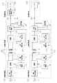
以下、本発明に係る非接触充電システムを具体化した実施形態について図に従って説明する。また、図1は、本実施形態の非接触充電システム100及び非接触充電システム100に接続され、充電されるバッテリを備える携帯機器本体(機器)200についての構成を示すブロック図である。図2は、非接触充電システム100と、非接触充電システム100に接続され、充電されるバッテリを備える携帯機器本体200を示す図である。 DESCRIPTION OF EMBODIMENTS Hereinafter, an embodiment embodying a non-contact charging system according to the present invention will be described with reference to the drawings. FIG. 1 is a block diagram showing a configuration of a
図1に示すように、非接触充電システム100は、大きく分けて、外部電源Eに接続される非接触送電装置10と、非接触送電装置10から非接触で電力が送電される非接触受電装置20から構成されている。そして、図1及び図2に示すように、携帯機器本体200は、非接触受電装置20と接続端子N1,N2を介して電気的に接続可能に構成されている。本実施形態では、非接触受電装置20は、携帯機器本体200のバッテリーカバーとして構成されており、携帯機器本体200に着脱可能に組み込むことができるようになっている。 As shown in FIG. 1, the
次に、非接触送電装置10について図1に基づき説明する。
非接触送電装置10は、電圧安定化回路11、送電部12、1次コイルL1、電圧検出回路13、1次側制御部14を備えている。Next, the non-contact
The non-contact
電圧安定化回路11は、外部電源Eから入力される入力電力の電圧を安定化させる回路である。そして、電圧安定化回路11には、送電部12が接続されている。送電部12は、電力を送る際には、所定周波数の交流電力を生成する。また、送電部12は、信号送信時には、送信する信号に応じた周波数の交流電力を生成し、送電部12に接続された1次コイルL1に出力するようになっている。なお、送電部12は、データ「1」に応じた信号を出力する際には、周波数f1の交流電力を生成して出力する一方、データ「0」に応じた信号を出力する際には、周波数f2の交流電力を生成して出力する。 The
1次コイルL1は、交流電力が入力されることにより、交流電力の周波数に応じた周波数の交番磁束が発生するようになっている。そして、1次コイル(送電側コイル)L1は、2次コイル(受電側コイル)L2と電磁結合して、電力を伝送するようになっている。電圧検出回路13は、1次コイルL1の誘導起電力(電圧)を検出する回路である。そして、電圧検出回路13は、1次側制御部14と接続されており、検出した誘導起電力(電圧)の波形を1次側制御部14に出力するようになっている。 The primary coil L1 is configured to generate an alternating magnetic flux having a frequency corresponding to the frequency of the AC power when AC power is input. The primary coil (power transmission side coil) L1 is electromagnetically coupled to the secondary coil (power reception side coil) L2 to transmit electric power. The
1次側制御部14は、中央演算処理装置(CPU)、記憶装置(不揮発性メモリー(ROM)、揮発性メモリー(RAM)など)を有するマイクロコンピュータを中心に構成されており、メモリーに格納されている各種データ及びプログラムに基づいて、送電部12の発振制御などの各種制御を実行する。 The primary
また、1次側制御部14は、送電部12と接続されている。そして、1次側制御部14は、非接触送電装置10が非接触受電装置20に信号を送信する際、送電部12に対して、送信する信号(又は送信する信号に応じた周波数)を通知して、送電部12に送信する信号に応じた周波数の交流電力を生成させるようになっている。 Further, the primary
また、1次側制御部14は、電圧検出回路13から受信した1次コイルL1の誘導起電力の変化を測定して、信号検出、異物検出などを行うようになっている。例えば、非接触受電装置20の信号制御回路24が非接触送電装置10に対して信号を送信するための負荷変調処理を実行すると、1次コイルL1の誘導起電力の波形が変化する。すなわち、非接触受電装置20が、「0」の信号を送信するため、負荷を小さくすると、1次コイルL1の誘導起電力の信号波形の振幅が小さくなり、「1」の信号を送信するため、負荷を大きくすると、信号波形の振幅が大きくなる。従って、誘導起電力のピーク電圧が閾値を超えたか否かにより、信号の種類を判別できるようになっている。なお、本実施形態の1次側制御部14は、非接触受電装置20からの無線通信信号を復調するとともに、復調された信号を解析して、同解析結果に基づいて送電部12の発振(周波数)を制御するようになっている。また、ROMには、各種閾値や、後に詳述する非接触受電装置20との間の無線通信信号の復調、同復調された信号の解析などに必要とされる各種のパラメータなどが予め保存されている。 Further, the primary
次に、非接触受電装置20について図1に基づき説明する。
非接触受電装置20は、非接触送電装置10からの交番磁束を受ける2次コイルL2と、受電部21と、2次側制御部22と、信号検出回路23と、信号制御回路24を備えている。Next, the non-contact
The non-contact
受電部21は、2次コイルL2が交番磁束を受けることにより2次コイルL2に流れる交流電力(誘導起電力)を直流電力に変換する整流回路を有する。整流回路は、整流ダイオードと、整流ダイオードにて整流された電力を平滑化させる平滑コンデンサとを備えており、2次コイルL2から入力された交流電力を直流電力に変換する、いわゆる半波整流回路として構成されている。なお、この整流回路の構成は、交流電力を直流電力に変換する整流回路としての一例に過ぎず、この構成に限定されるものではなく、ダイオードブリッジを用いた全波整流回路やその他の周知の整流回路の構成を有していてもよい。信号検出回路23は、2次コイルL2の誘導起電力を検出する回路である。そして、信号検出回路23は、2次側制御部22と接続されており、検出した誘導起電力(電圧)の波形を2次側制御部22に出力するようになっている。 The power reception unit 21 includes a rectifier circuit that converts AC power (inductive electromotive force) flowing through the secondary coil L2 into DC power when the secondary coil L2 receives the alternating magnetic flux. The rectifier circuit includes a rectifier diode and a smoothing capacitor that smoothes the power rectified by the rectifier diode, and converts the AC power input from the secondary coil L2 into DC power, a so-called half-wave rectifier circuit. It is configured as. The configuration of this rectifier circuit is merely an example of a rectifier circuit that converts AC power into DC power, and is not limited to this configuration. A full-wave rectifier circuit using a diode bridge or other known rectifier circuit is also used. You may have the structure of a rectifier circuit. The
信号制御回路24は、非接触受電装置20から非接触送電装置10に信号を送信する場合、送信する信号に応じて2次コイルL2にかかる負荷を変化させて、1次コイルL1の誘導起電力の信号波形を変化させる負荷変調処理を行う。この信号制御回路24は、2次側制御部22と接続されており、2次側制御部22からの制御信号に基づき、負荷変調処理を実行する。 When the
2次側制御部22は、中央演算処理装置(CPU)、記憶装置(ROM、RAMなど)を有するマイクロコンピュータを中心に構成されている。そして、2次側制御部22は、メモリーに格納されている各種データ及びプログラムに基づいて、接続端子N1,N2を介して接続される携帯機器本体200のバッテリBAの充電状態を判定するとともに充電量制御などの各種制御を実行することができるようになっている。なお、本実施形態では、バッテリBAの充電量に基づいて非接触送電装置10への信号を生成するようになっている。また、ROMには、バッテリ(本負荷)BAの充電量の判定等の充電量制御に必要とされる各種情報や、非接触送電装置10との間の信号の生成や、同信号に基づく変調のために必要とされる各種のパラメータなどが予め保存されている。 The secondary
そして、2次側制御部22には、バッテリBAの正極及び負極がそれぞれ接続され、バッテリBAから駆動用の電力供給を受けるようになっている。また、2次側制御部22は、受電部21から入力した交流電力を予め決められた電圧に調節して充電電力を生成し、接続端子N1,N2を介してバッテリBAに出力するようになっている。また、2次側制御部22は、バッテリBAの充電量に応じて充電電力を出力するか否かを切り替えるようになっている。例えば、2次側制御部22は、バッテリBAの端子間電圧が予め設定された充電量判定用の閾値よりも低くいことなどからバッテリBAを充電することが好ましいと判断される場合、充電電力をバッテリBAに供給する。一方、バッテリBAの端子間電圧が上記の充電量判定用の閾値よりも高いことなどからバッテリBAを充電する必要が無いと判断される場合、2次側制御部22は、充電電力をバッテリBAに供給しない。 The
また、2次側制御部22は、非接触送電装置10と信号の送受信をする場合には、充電電力の出力を停止するようになっている。また、2次側制御部22は、動作電圧が動作可能な電圧よりも低い場合、バッテリBAとの接続を遮断し、バッテリからの電力の逆流を防止するようになっている。 Moreover, the secondary
また、2次側制御部22は、2次コイルL2の誘導起電力の波形を監視して、1次コイルL1と2次コイルL2の位置関係が適正であるか否かを判断するようになっている。また、2次側制御部22は、2次コイルL2の誘導起電力の周波数を監視して、非接触送電装置10からの信号がデータ「1」であるか又はデータ「0」であるかを判断するようになっている。 Further, the
本実施形態では、図2に示すように、携帯機器本体200は、非接触受電装置20と着脱可能に構成されている。そして、携帯機器本体200には、通常、バッテリBAの充電状態を判定するとともにその充電量制御を行う充電管理部(機器側充電制御部)201を備えているもの(図1(a)参照)と、備えていないもの(図1(b)参照)が存在する。このため、本実施形態の2次側制御部22には、接続された携帯機器本体200のバッテリBAの充電量を把握すると共に、携帯機器本体200に充電管理部201が備えられていた場合にその充電管理部201による制御を優先させるための監視回路25が接続されている。 In the present embodiment, as shown in FIG. 2, the
監視回路25は、2次側制御部22と接続されているとともに、接続端子N1,N2を介して充電管理部201と接続可能に構成されている。そして、監視回路25は、バッテリBAの電圧が、携帯機器本体200側において予め設定された満充電判定値(第2の満充電判定値)以上である場合に充電管理部201から出力される充電完了信号を入力することができるようになっている。充電完了信号は、充電量が十分で、充電が不要である状態(満充電状態)である旨を示す信号である。そして、監視回路25は、充電完了信号を充電管理部201から入力した場合には、充電完了信号を2次側制御部22に出力するようになっている。この充電完了信号に基づき、2次側制御部22は、充電量制御を実行するようになっている。 The
また、監視回路25は、バッテリBAの電圧が携帯機器本体200側において予め設定された再充電判定値(第2の再充電判定値)以下である場合に充電管理部201から出力される再充電要求信号を入力することができるようになっている。再充電要求信号は、充電量が不十分で充電が必要である状態(再充電可能状態)である旨を示す信号である。そして、監視回路25は、再充電要求信号を充電管理部201から入力した場合には、再充電要求信号を2次側制御部22に出力するようになっている。この再充電要求信号に基づき、2次側制御部22は、充電量制御を実行するようになっている。 In addition, the
その一方で、監視回路25は、接続端子N1,N2を介してバッテリBAの正極及び負極がそれぞれ接続され、バッテリBAの電圧を把握することができるようになっている。このため、携帯機器本体200の充電管理部201から充電完了信号及び再充電要求信号を入力しなかった場合、監視回路25は、バッテリBAの電圧に基づき、充電管理部201の代わりに、充電完了信号及び再充電要求信号を2次側制御部22に出力する。すなわち、監視回路25は、バッテリBAの電圧が、非接触受電装置20側において予め設定された満充電判定値(第1の満充電判定値)以上である場合には、充電完了信号を2次側制御部22に出力する。また、監視回路25は、バッテリBAの電圧が、非接触受電装置20側において予め設定された再充電判定値(第1の再充電判定値)以下である場合には、再充電要求信号を2次側制御部22に出力する。 On the other hand, the
なお、本実施形態では、第1の満充電判定値(例えば、4.5V)は、第2の満充電判定値(例えば、4.2V)よりも大きな値が設定されている。これにより、充電管理部201が接続されていた場合、監視回路25よりも充電管理部201の方が早く充電完了信号を出力することができるようになっている。また、本実施形態では、第1の再充電判定値(例えば、3.2V)は、第2の再充電判定値(例えば、3.8V)よりも小さな値が設定されている。これにより、充電管理部201が接続されていた場合、監視回路25よりも充電管理部201の方が早く再充電要求信号を出力することができるようになっている。 In the present embodiment, the first full charge determination value (for example, 4.5V) is set to a value larger than the second full charge determination value (for example, 4.2V). Thereby, when the
監視回路25の回路構成の一例を具体的に図3に基づき説明する。監視回路25は、図3に示すように、接続端子N1を介して接続されたバッテリBAの正極に、抵抗R1の一端が接続され、抵抗R1の他端がノードN0に接続されている。また、ノードN0に抵抗R2の一端が接続され、抵抗R2の他端がグランドに設置されている。そして、2次側制御部22は、ノードN0と接続されており、抵抗R1,R2により分圧された電圧を入力するようになっている。 An example of the circuit configuration of the
また、接続端子N1を介して接続されたバッテリBAの正極に、(PNP型)トランジスタQ2のエミッタ端子が接続されている。このトランジスタQ2のコレクタ端子は、ノードN0と接続されている。そして、トランジスタQ2のベース端子が接続端子N2を介して充電管理部201と接続されている。また、トランジスタQ2のエミッタ端子は、抵抗R3を介してトランジスタQ2のベース端子及び充電管理部201の接続端子N2と接続されている。充電管理部201は、接続端子N2を介して充電完了信号を入力するようになっている。 The emitter terminal of the (PNP type) transistor Q2 is connected to the positive electrode of the battery BA connected via the connection terminal N1. The collector terminal of the transistor Q2 is connected to the node N0. The base terminal of the transistor Q2 is connected to the
また、ノードN0に、(NPN型)トランジスタQ1のコレクタ端子が接続されている。このトランジスタQ1のエミッタ端子は、グランドに接地されている。そして、トランジスタQ1のベース端子が接続端子N2を介して充電管理部201と接続されている。また、トランジスタQ1のエミッタ端子は、抵抗R4を介してトランジスタQ1のベース端子及び充電管理部201の接続端子N2と接続されている。充電管理部201は、接続端子N2を介して再充電要求信号を入力するようになっている。 The collector terminal of the (NPN type) transistor Q1 is connected to the node N0. The emitter terminal of this transistor Q1 is grounded. The base terminal of the transistor Q1 is connected to the
また、図3に示すように、バッテリBAの正極に、抵抗R3と同じ抵抗値の抵抗R5の一端が接続され、抵抗R5の他端がノードN10に接続されている。また、ノードN10に抵抗R4と同じ抵抗値の抵抗R6の一端が接続され、抵抗R6の他端がグランドに設置されている。そして、充電管理部201は、ノードN10と接続され、ノードN10からの分圧された電圧を入力するようになっている。 As shown in FIG. 3, one end of a resistor R5 having the same resistance value as that of the resistor R3 is connected to the positive electrode of the battery BA, and the other end of the resistor R5 is connected to the node N10. Further, one end of a resistor R6 having the same resistance value as that of the resistor R4 is connected to the node N10, and the other end of the resistor R6 is installed on the ground. The
この監視回路25の動作について説明する。
接続端子N1,N2を介して充電管理部201が接続されている場合(存在する場合)について説明する。バッテリBAの電圧が第2の満充電判定値以上となった場合、充電管理部201は、接続端子N2をグランドに接地するように切替える。これにより、トランジスタQ2がオンとなり、バッテリBAの電圧が抵抗R1,R2により分圧されることなく、2次側制御部22に入力される。これにより、バッテリBAの電圧が分圧されることなく2次側制御部22に直接入力されることとなり、2次側制御部22は、入力した電圧が第1の満充電判定値以上であると判断して、充電が完了したと判定することとなる。The operation of the
A case where the
このため、本実施形態では、充電管理部201が、接続端子N1をグランドに接地して、トランジスタQ2をオンにすることが、充電管理部201による充電完了信号の出力ということとなる。また、監視回路25が、バッテリBAの電圧をそのまま出力することが、充電管理部201の指示に基づく、監視回路25による充電完了信号の出力ということとなる。 For this reason, in the present embodiment, when the
バッテリBAの電圧が第2の再充電判定値以下となった場合、充電管理部201は、接続端子N2に電流を流す。これにより、トランジスタQ1がオンとなり、ノードN0がグランドに接地される。つまり、2次側制御部22が接地される。従って、2次側制御部22は、入力した電圧が第1の再充電判定値以下であると判断して、充電を要求する。 When the voltage of the battery BA becomes equal to or lower than the second recharge determination value, the
このため、本実施形態では、充電管理部201が、トランジスタQ1をオンにすることが、充電管理部201による再充電要求信号の出力ということとなる。また、監視回路25が、グランドに接地することが、充電管理部201の指示に基づく、監視回路25による再充電要求信号の出力ということとなる。 For this reason, in the present embodiment, turning on the transistor Q1 in the
次に、充電管理部201が接続されていない場合(存在しない場合)について説明する。2次側制御部22には、抵抗R1,R2により分圧されたバッテリBAの電圧が入力されるようになっている。2次側制御部22は、当該電圧が第1の満充電判定値以上であるか否かを判定することにより、満充電状態であるか否かを判定する。従って、第1の満充電判定値以上の電圧を出力することが、監視回路25による充電完了信号の出力ということとなる。また、2次側制御部22は、当該電圧が第1の再充電判定値以下であるか否かを判定することにより、再充電可能状態であるか否かを判定する。従って、第1の再充電判定値以下の電圧を出力することが、監視回路25による再充電要求信号の出力ということとなる。 Next, a case where the
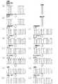
次に、バッテリBAの充電に係わる制御について説明する。まず、携帯機器本体200に充電管理部201が備えられていない場合について図4及び図5に基づき説明する。
1次側制御部14は、待機状態(非接触受電装置20と電磁的に接続されていないとき)であるとき、所定の検知周期毎に、機器検知信号を出力するようになっている(ステップS10)。この機器検知信号は、図5(a)に示すように、間欠的に出力されるようになっており、その機器検知信号の送信時の電力は、単位時間当たりにおいて、充電電力伝送時(充電時)の電力、データ「0」又は「1」の信号を送信するときの電力よりも小さいものとなっている。Next, control related to charging of the battery BA will be described. First, the case where the
When the primary
そして、非接触送電装置10は、この機器検知信号を出力すると共に、非接触受電装置20が設置されたか否かを判定する機器設置判定を実行するようになっている(ステップS11)。より詳しく説明すると、非接触送電装置10が待機状態であるときに、非接触受電装置20が所定の場所に設置され、1次コイルL1と2次コイルL2が電磁的に結合すると、図5(b)に示すように、1次コイルL1が2次コイルL2の影響を受けて、機器検知信号の波形が変化する。具体的には、機器検出信号出力時における1次コイルL1の交流電力のピーク電圧が小さくなるように変化する。従って、1次側制御部14は、機器設置判定において、機器検知信号の波形が変化した場合には、非接触受電装置20が設定されたと判定(肯定判定)するようになっている。一方、1次側制御部14は、機器設置判定において、機器検知信号の波形が変化せずに、一定時間経過した場合には、非接触受電装置20が設定されていないと判定(否定判定)するようになっている。 And the non-contact
1次側制御部14は、機器設置判定(ステップS11)において否定判定した場合、所定時間経過後、再びステップS10の処理を実行して、機器検知信号を再び出力する。一方、1次側制御部14は、機器設置判定(ステップS11)において肯定判定した場合、非接触受電装置20に充電確認信号を出力する(ステップS12)。1次側制御部14は、充電確認信号を出力する際、充電確認信号を信号「0」又は「1」の組み合わせに変換し(変調し)、図5(c)に示すように、当該変換後の信号を順番に出力させるように送電部12を制御する。これにより、2次コイルL2の誘導起電力は、図5(i)に示すように、充電確認信号に応じて、その波形が変化する。 If a negative determination is made in the device installation determination (step S11), the primary
2次側制御部22は、信号検出回路23が検出した「0」又は「1」からなる信号を復調及び解析して、充電確認信号を受信したと判定すると、バッテリBAの電圧に基づき、充電量を判定する。前提より、携帯機器本体200には充電管理部201が備えられていないため、2次側制御部22は、監視回路25を介して入力されたバッテリBAの電圧が第1の再充電判定値以下であるか否かを判定する。そして、2次側制御部22は、充電が可能である場合(バッテリBAの電圧が第1の再充電判定値以下である場合)、充電確認信号に応じた第1の応答信号(再充電要求信号)を2次コイルL2に出力させる(ステップS21)。具体的には、2次側制御部22は、図5(j)に示すように、信号制御回路24に対して第1の応答信号を出力させるように2次コイルL2に掛かる負担を変化させる。これにより、図5(d)に示すように、1次コイルL1の誘導起電力の電圧が変化することとなる。なお、2次側制御部22は、充電が不要である場合(バッテリBAの電圧が閾値以上である場合)、第1の応答信号を出力することなく、処理を終了する。 When the secondary
1次側制御部14は、電圧検出回路13が検出した誘導起電力の波形に基づき、信号を復調し、第1の応答信号を入力したか否かを判定(すなわち、非接触受電装置20から信号が返信されたか否かの確認を)する(ステップS13)。この判定結果が否定の場合(充電が不要である場合、又は電磁的に接続されていない場合)、1次側制御部14は、所定時間経過後、再びステップ10の処理を実行する。 The primary
一方、1次側制御部14は、ステップS13の判定結果が肯定の場合(第1の応答信号を受信すると)、ID認証を行うための1Dを示すID確認信号を出力させる(ステップS14)。なお、ID確認信号を出力する際の処理は、充電確認信号の出力時の処理と同様である。具体的には、1次側制御部14は、ID確認信号を出力させる際、ID確認信号を信号「0」又は「1」の組み合わせに変換し(変調し)、図5(e)に示すように、当該変換後の信号を順番に出力させるように送電部12を制御する。これにより、2次コイルL2の誘導起電力は、図5(k)に示すように、ID確認信号に応じて、その波形が変化する。 On the other hand, when the determination result of step S13 is affirmative (when the first response signal is received), the primary
2次側制御部22は、信号検出回路23が検出した「0」又は「1」からなる信号を復調及び解析して、ID確認信号を受信したと判定すると、充電可能な機器(非接触送電装置10)のIDであるか否かを判定する。そして、2次側制御部22は、充電が可能な機器のIDである場合(ID認証が完了(確立)した場合)、ID確認信号に応じた第2の応答信号を出力させる(ステップS22)。具体的には、2次側制御部22は、図5(l)に示すように、信号制御回路24に対して第2の応答信号を出力させるように2次コイルL2に掛かる負担を変化させる。これにより、図5(f)に示すように、1次コイルL1の誘導起電力の電圧が変化することとなる。なお、2次側制御部22は、ID認証が失敗した(充電可能な機器でない)場合、第2の応答信号を出力させることなく、処理を終了する。 When the secondary-
1次側制御部14は、電圧検出回路13が検出した誘導起電力の波形に基づき、信号を復調し、第2の応答信号を入力したか否かを判定(すなわち、非接触受電装置20から信号が返信されたか否かの確認を)する(ステップS15)。この判定結果が否定の場合(ID認証に失敗した場合)、1次側制御部14は、所定時間経過後、再びステップ10の処理を実行する。 The primary
一方、1次側制御部14は、ステップS15の判定結果が肯定の場合(第2の応答信号を受信すると)、充電電力伝送時の電力を1次コイルL1に入力して充電を開始させる(ステップS16)。充電電力伝送時の電力は、機器検知信号出力時の電力よりも大きく、継続的に出力され続けられるようになっている。2次側制御部22は、第2の応答信号出力後、2次コイルL2及び受電部21を介して入力した直流電力の電圧を制御して、所定電圧の充電電力を生成し、接続端子を介してバッテリBAに供給する。これにより、2次側制御部22は、充電を開始する(ステップS23)。 On the other hand, when the determination result of step S15 is affirmative (when the second response signal is received), the primary
2次側制御部22は、充電開始後、監視回路25から入力されるバッテリBAの電圧に基づき、充電量を監視し続け、充電が完了したか否かを判定する(ステップS24)。具体的には、2次側制御部22は、バッテリBAの電圧が、第1の満充電判定値以上であるか否かを判定する。2次側制御部22は、ステップS24の判定結果が否定の場合(充電が完了していない場合)、所定時間経過後、再びステップS24の処理を実行する。 After the start of charging, the secondary
一方、ステップS24の判定結果が肯定の場合(充電が完了した場合)、2次側制御部22は、充電が完了した旨を示す充電完了信号を出力させる(ステップS25)。具体的には、2次側制御部22は、図5(n)に示すように、信号制御回路24に対して充電完了信号を出力させるように2次コイルL2に掛かる負担を変化させる。これにより、図5(h)に示すように、1次コイルL1の誘導起電力の電圧が変化することとなる。 On the other hand, when the determination result of step S24 is affirmative (when charging is completed), the
一方、ステップS16の処理後(充電開始後)、1次側制御部14は、非接触受電装置20がそのまま設置されているか否かを判定する機器設置判定を実行するようになっている(ステップS17)。より詳しく説明すると、非接触送電装置10が充電状態であるときに、非接触受電装置20が所定の場所から取り外されると、1次コイルL1と2次コイルL2が電磁的な結合が解除され、充電時に流れる1次コイルL1の電力の波形が変化する。具体的には、充電時に流れる1次コイルL1の電力のピーク電圧が大きくなるように変化する。従って、1次側制御部14は、ステップS17の機器設置判定において、充電時に流れる1次コイルL1の電力の波形が変化した場合には、非接触受電装置20が取り外されたと判定(否定判定)するようになっている。一方、1次側制御部14は、ステップS17の機器設置判定において、充電時に流れる1次コイルL1の電力の波形が変化せずに、一定時間経過した場合には、非接触受電装置20が設置されたままであると判定(肯定判定)するようになっている。 On the other hand, after the processing of step S16 (after the start of charging), the primary-
1次側制御部14は、ステップS17の機器設置判定が否定となった場合、ステップS10の処理に移行する。一方、1次側制御部14は、ステップS17の機器設置判定が肯定である場合、充電完了信号を入力したか否かを判定する(ステップS18)。ステップS18の処理を具体的に説明すると、1次側制御部14は、電圧検出回路13が検出した誘導起電力の波形に基づき、信号を復調し、充電完了信号を入力したか否かを判定する。この判定結果が否定の場合、1次側制御部14は、充電開始(ステップS16)から予め決められた充電時間が経過したか否かを判定する(ステップS19)。なお、充電時間は、バッテリBAの充電量が空の状態から満充電となるのに十分な時間であり、実験により設定される。 The primary
ステップS19の判定結果が肯定の場合、1次側制御部14は、充電完了であると判定し、処理を終了する。一方、ステップS19の判定結果が否定の場合、1次側制御部14は、所定時間経過後、再びステップS17の処理を実行する。また、ステップS18の判定結果が肯定の場合(充電完了信号を入力した場合)、1次側制御部14は、充電完了であると判定し、処理を終了する。 If the determination result of step S19 is affirmative, the primary-
次に、携帯機器本体200に充電管理部201が備えられている場合におけるバッテリBAの充電に係わる制御について図3に基づき説明する。なお、携帯機器本体200に充電管理部201が備えられていない場合と基本的に同じ制御であるため、詳細な説明及び図の一部を省略する。 Next, control related to charging of the battery BA when the
1次側制御部14は、待機状態(非接触受電装置20と電磁的に接続されていないとき)であるとき、所定の検知周期毎に、機器検知信号を出力させるようになっている(ステップS10)。そして、非接触送電装置10は、この機器検知信号を出力すると共に、非接触受電装置20が設置されたか否かを判定する機器設置判定を実行するようになっている(ステップS11)。1次側制御部14は、機器設置判定(ステップS11)において否定判定した場合、所定時間経過後、再びステップS10の処理を実行して、機器検知信号を再び出力させる。一方、1次側制御部14は、機器設置判定(ステップS11)において肯定判定した場合、非接触受電装置20に充電確認信号を出力させる(ステップS12)。 When the primary
2次側制御部22は、信号検出回路23が検出した「0」又は「1」からなる信号を復調及び解析して、充電確認信号を受信したと判定すると、バッテリBAの電圧に基づき、充電量を判定する。前提より、携帯機器本体200には充電管理部201が備えられているため、2次側制御部22は、充電管理部201から監視回路25を介して再充電要求信号を入力した場合、充電が可能であると判定する。2次側制御部22は、充電が可能である場合(バッテリBAの電圧が第1の再充電判定値以下である場合)、充電確認信号に応じて第1の応答信号(再充電要求信号)を出力させる(ステップS21)。 When the secondary
1次側制御部14は、電圧検出回路13が検出した誘導起電力の波形に基づき、信号を復調し、第1の応答信号を入力したか否かを判定する(ステップS13)。この判定結果が否定の場合、1次側制御部14は、所定時間経過後、再びステップ10の処理を実行する。一方、1次側制御部14は、ステップS13の判定結果が肯定の場合、ID認証を行うための1Dを示すID確認信号を出力させる(ステップS14)。 The primary
2次側制御部22は、ID確認信号を受信したと判定すると、充電可能な機器のIDであるか否かを判定する。そして、2次側制御部22は、充電が可能な機器(非接触送電装置10)のIDである場合、ID確認信号に応じた第2の応答信号を出力させる(ステップS22)。1次側制御部14は、第2の応答信号を入力したか否かを判定する(ステップS15)。この判定結果が否定の場合(ID認証に失敗した場合)、1次側制御部14は、所定時間経過後、再びステップ10の処理を実行する。一方、1次側制御部14は、ステップS15の判定結果が肯定の場合、充電電力伝送時の電力にて充電を開始させる(ステップS16)。2次側制御部22は、第2の応答信号出力後、充電を開始する(ステップS23)。 If the secondary
2次側制御部22は、充電開始後、監視回路25から入力されるバッテリBAの電圧に基づき、充電量を監視し続け、充電が完了したか否かを判定する(ステップS24)。具体的には、2次側制御部22は、充電管理部201から監視回路25を介して充電完了信号を入力した場合、充電が完了したと判定する。2次側制御部22は、ステップS24の判定結果が否定の場合(充電が完了していない場合)、所定時間経過後、再びステップS24の処理を実行する。一方、ステップS24の判定結果が肯定の場合(充電が完了した場合)、2次側制御部22は、充電が完了した旨を示す充電完了信号を非接触送電装置10に出力させる(ステップS25)。 After the start of charging, the secondary
一方、ステップS16の処理後(充電開始後)、1次側制御部14は、非接触受電装置20がそのまま設置されているか否かを判定する機器設置判定を実行するようになっている(ステップS17)。1次側制御部14は、ステップS17の機器設置判定が否定となった場合、ステップS10の処理に移行する。一方、1次側制御部14は、ステップS17の機器設置判定が肯定である場合、充電完了信号を入力したか否かを判定する(ステップS18)。この判定結果が否定の場合、1次側制御部14は、充電開始(ステップS16)から予め決められた充電時間が経過したか否かを判定する(ステップS19)。 On the other hand, after the processing of step S16 (after the start of charging), the primary-
ステップS19の判定結果が肯定の場合、1次側制御部14は、充電完了であると判定し、処理を終了する。一方、ステップS19の判定結果が否定の場合、1次側制御部14は、所定時間経過後、再びステップS17の処理を実行する。また、ステップS18の判定結果が肯定の場合(充電完了信号を入力した場合)、1次側制御部14は、充電完了であると判定し、処理を終了する。 If the determination result of step S19 is affirmative, the primary-
以上詳述したように、本実施形態は、以下の効果を有する。
(1)2次側制御部22は、監視回路25を介してバッテリBAの電圧(充電量)を計測し、電圧に基づきバッテリBAに対して電力を供給するか否かを決定する。このため、携帯機器本体200にバッテリBAの充電量を管理する充電管理部201が備えられていなくても、正常にバッテリBAを充電することができる。過充電を防止すると共に、正確に再充電することができる。As described above in detail, the present embodiment has the following effects.
(1) The
(2)充電管理部201が備えられていた場合、2次側制御部22は、充電管理部201からの制御信号に基づき、バッテリBAの充電を管理する。すなわち、充電管理部201が、バッテリBAの電圧を監視し、第1の再充電要求信号以下である場合には、監視回路25を介して、2次側制御部22に再充電要求信号を出力する。2次側制御部22は、この再充電要求信号を入力すると、充電可能であると判定し、充電を開始させる。また、充電管理部201が、バッテリBAの電圧を監視し、第1の充電完了信号以上である場合には、監視回路25を介して、2次側制御部22に充電完了信号を出力する。2次側制御部22は、この充電完了信号を入力すると、充電不要であると判定し、充電を終了させる。これにより、携帯機器本体200に設けられた充電管理部201により充電制御が実行されるため、携帯機器本体200のバッテリBAに最適な充電管理をすることができる。 (2) When the
(3)充電管理部201は、第2の満充電判定値以上である場合、充電完了信号を出力するようになっている一方、2次側制御部22は、バッテリBAの電圧が第1の満充電判定値以上となった場合に、充電不要であると判定し、充電完了信号を出力させるようになっている。そして、第2の満充電判定値は、第1の満充電判定値よりも小さい値が設定されている。このため、充電管理部201の方が、2次側制御部22よりも早く充電が完了したことを判定することができ、充電終了に関する制御について充電管理部201による充電制御を優先することができる。従って、携帯機器本体200に設けられた充電管理部201により充電制御が実行されるため、携帯機器本体200のバッテリBAに最適な充電管理をすることができる。 (3) When the
(4)充電管理部201は、第2の再充電判定値以下である場合、再充電要求信号を出力するようになっている一方、2次側制御部22は、バッテリBAの電圧が第1の再充電判定値以下となった場合に、充電可能であると判定し、再充電要求信号を出力させるようになっている。そして、第2の再充電判定値は、第1の再充電判定値よりも大きい値が設定されている。このため、充電管理部201の方が、2次側制御部22よりも早く充電が可能であることを判定することができ、充電が可能であるか否かに関する制御について充電管理部201による充電制御を優先することができる。従って、携帯機器本体200に設けられた充電管理部201により充電制御が実行されるため、携帯機器本体200のバッテリBAに最適な充電管理をすることができる。 (4) When the
なお、上記実施形態は以下のように変更してもよい。
・上記実施形態において、監視回路25は、2次側制御部22に組み込まれていても良い。In addition, you may change the said embodiment as follows.
In the above embodiment, the
・上記実施形態において、携帯機器本体200は、携帯電話であってもよいし、電気カミソリ、電動歯ブラシ、ノートパソコンなどであってもよい。
・上記実施形態において、ID認証を行っていたが、行わなくても良い。In the above embodiment, the
-Although ID authentication was performed in the said embodiment, it does not need to perform.
・上記実施形態において、1時側制御部14を備えたが、備えなくても良い。この場合、機器設置判定が肯定となった場合、非接触送電装置10は、充電を開始することとなる。また、タイマーにて充電時間が経過した場合、非接触送電装置10は、充電を終了することとなる。また、非接触受電装置20は、バッテリBAの電圧が第1の満充電判定値又は第2の満充電判定値以上となった場合、充電を終了する(充電電力の供給を終了する)こととなる。 -Although the 1 o'clock
・上記実施形態では、1次側制御部14は、ステップS19にて、充電開始から予め決められた充電時間が経過した場合、機器検知信号を間欠的に出力させたが、充電完了信号を受信するまで、又は非接触受電装置20が取り外されるまで、充電を継続しても良い。 In the above embodiment, the
・上記実施形態において、1次側制御部14は、充電開始から予め決められた充電時間が経過するまで、充電を継続しても良い。
・上記実施形態において、第1の再充電判定値は、第2の再充電判定値よりも小さい値が設定されていたが、同じ値にしてもよい。また、第1の再充電判定値に、第2の再充電判定値よりも大きい値を設定してもよい。In the above embodiment, the primary
In the above embodiment, the first recharge determination value is set to a value smaller than the second recharge determination value, but may be the same value. Further, a value larger than the second recharge determination value may be set as the first recharge determination value.
・上記実施形態において、第1の満充電判定値は、第2の満充電判定値よりも大きい値が設定されていたが、同じ値にしてもよい。また、第1の満充電判定値に、第2の満充電判定値よりも小さい値を設定してもよい。 In the above embodiment, the first full charge determination value is set to a value larger than the second full charge determination value, but may be the same value. In addition, a value smaller than the second full charge determination value may be set as the first full charge determination value.
・上記実施形態では、非接触受電装置20は、バッテリーカバーとして構成されているが、携帯機器本体200に着脱可能であれば、任意に構成を変更しても良い。
・上記実施形態において、非接触受電装置20の信号制御回路24が負荷変調処理を実行した際、1次側制御部14は、ピーク電圧が閾値を超えたか否かにより信号を判定したが、変化量が一定値以上であるか否かにより信号を判定しても良い。-In above-mentioned embodiment, although the non-contact
In the above embodiment, when the
・上記実施形態において、2次側制御部22は、バッテリBAから駆動用の電力供給を受けていたが、受電部21から供給されてもよい。
・上記実施形態において、1次側制御部14は、機器設置判定において、非接触受電装置20が設定されたと判定(肯定判定)した場合、非接触受電装置20に充電確認信号を出力させたが、非接触受電装置20から非接触送電装置10に充電確認信号を出力するようにしても良い。In the above-described embodiment, the
In the above embodiment, the primary-
・上記実施形態では、バッテリBAの充電量を判定するタイミングは、第1の応答信号出力前であったが、充電開始までの間に、充電量を判定すればよい。
・上記実施形態において、充電量を判定した際、充電が不要であると判定した場合、第1の応答信号を出力することなく、処理を終了するとしていたが、充電が不要である旨の応答信号を非接触送電装置10に出力しても良い。In the above embodiment, the timing for determining the charge amount of the battery BA is before the output of the first response signal, but the charge amount may be determined before the start of charging.
In the above embodiment, when determining the amount of charge, if it is determined that charging is not required, the processing is terminated without outputting the first response signal, but a response indicating that charging is not required A signal may be output to the non-contact
・上記実施形態では、2次側制御部22は、ID認証が失敗した(充電可能な機器でない)場合、第2の応答信号を出力させることなく、処理を終了したが、ID認証が失敗した(充電可能な機器でない)旨を応答信号として非接触送電装置10に出力しても良い。 -In above-mentioned embodiment, when ID authentication failed (it is not a device which can be charged), the secondary
・上記実施形態において、IDを2次側制御部22で判定したが、1次側制御部14で判定しても良い。
・上記実施形態において、充電開始後、1次側制御部14は、非接触受電装置20がそのまま設置されているか否かを判定(機器設置判定)する際、1次コイルL1の電力波形にて判定したが、所定の周期毎に信号通信を行うことにより判定しても良い。In the above embodiment, the ID is determined by the
In the above embodiment, after starting charging, the
・上記実施形態において、充電開始から予め決められた充電時間が経過したか否かを判定する機能はなくてもよい。 In the above embodiment, there may be no function for determining whether a predetermined charging time has elapsed since the start of charging.
100…非接触充電システム、200…携帯機器本体、10…非接触送電装置、11…電圧安定化回路、12…送電部、13…電圧検出回路、14…1次側制御部14、20…非接触受電装置、21…受電部、22…2次側制御部、23…信号制御回路、24…信号検出回路、25…監視回路、201…充電管理部、BA…バッテリ、L1…1次コイル、L2…2次コイル。 DESCRIPTION OF
Claims (6)
Translated fromJapanese交流電力が供給される1次コイルから発生した交番磁束と交差する2次コイルと、
前記2次コイルの誘導起電力を前記負荷に供給する制御部と、を備え、
前記制御部は、前記負荷の充電量を計測し、充電量に基づき前記負荷に対して電力を供給するか否かを決定することを特徴とする非接触受電装置。In a non-contact power receiving apparatus that is connected to a device via a connection terminal and supplies power to a load of the device,
A secondary coil that intersects with the alternating magnetic flux generated from the primary coil to which AC power is supplied;
A controller that supplies the electromotive force of the secondary coil to the load,
The said control part measures the charge amount of the said load, and determines whether electric power is supplied with respect to the said load based on the charge amount, The contactless power receiving apparatus characterized by the above-mentioned.
前記第1の満充電判定値は、前記第2の満充電判定値よりも大きな値が設定されていることを特徴とする請求項2に記載の非接触受電装置。A second full-charge determination in which the load voltage is predetermined by the device-side charge control unit when the device includes a device-side charge control unit that measures the voltage of the load; When it is determined that the value is greater than or equal to the value, the charging for the load is configured to end,
The non-contact power receiving apparatus according to claim 2, wherein the first full charge determination value is set to be larger than the second full charge determination value.
前記第1の再充電判定値は、前記第2の再充電判定値よりも小さな値が設定されていることを特徴とする請求項4に記載の非接触受電装置。A second recharge determination in which the load voltage by the device-side charge control unit is determined in advance when the device includes a device-side charge control unit that measures the load voltage; When it is determined that the value is less than or equal to the value, the load is configured to supply power,
The contactless power receiving device according to claim 4, wherein the first recharge determination value is set to a value smaller than the second recharge determination value.
前記非接触受電装置は、
前記1次コイルから発生した交番磁束と交差することにより発生する前記2次コイルの誘導起電力を前記負荷に供給する制御部と、を備え、
前記制御部は、前記負荷の充電量を計測し、充電量に基づき前記負荷に対して電力を供給するか否かを決定することを特徴とする非接触充電システム。A non-contact power transmission device having a primary coil that generates an alternating magnetic flux when AC power is supplied, and a secondary coil that intersects with the alternating magnetic flux generated from the primary coil, via the secondary coil In a non-contact charging system comprising: a non-contact power receiving device that supplies AC power supplied from the primary coil to a load of a device connected through a connection terminal;
The non-contact power receiving device is:
A controller for supplying the load with the induced electromotive force of the secondary coil generated by crossing the alternating magnetic flux generated from the primary coil,
The said control part measures the charge amount of the said load, and determines whether electric power is supplied with respect to the said load based on the charge amount, The contactless charging system characterized by the above-mentioned.
Priority Applications (4)
| Application Number | Priority Date | Filing Date | Title |
|---|---|---|---|
| JP2010072990AJP2011205850A (en) | 2010-03-26 | 2010-03-26 | Noncontact power-receiving apparatus and noncontact charging system |
| US13/582,255US20120326661A1 (en) | 2010-03-26 | 2011-03-08 | Contactless power receiving device, and contactless charging system |
| PCT/JP2011/055312WO2011118377A1 (en) | 2010-03-26 | 2011-03-08 | Non-contact power-receiving device, and non-contact charging system |
| CN2011800118968ACN102823102A (en) | 2010-03-26 | 2011-03-08 | Contactless power receiving device, and contactless charging system |
Applications Claiming Priority (1)
| Application Number | Priority Date | Filing Date | Title |
|---|---|---|---|
| JP2010072990AJP2011205850A (en) | 2010-03-26 | 2010-03-26 | Noncontact power-receiving apparatus and noncontact charging system |
Publications (1)
| Publication Number | Publication Date |
|---|---|
| JP2011205850Atrue JP2011205850A (en) | 2011-10-13 |
Family
ID=44672942
Family Applications (1)
| Application Number | Title | Priority Date | Filing Date |
|---|---|---|---|
| JP2010072990AWithdrawnJP2011205850A (en) | 2010-03-26 | 2010-03-26 | Noncontact power-receiving apparatus and noncontact charging system |
Country Status (4)
| Country | Link |
|---|---|
| US (1) | US20120326661A1 (en) |
| JP (1) | JP2011205850A (en) |
| CN (1) | CN102823102A (en) |
| WO (1) | WO2011118377A1 (en) |
Cited By (3)
| Publication number | Priority date | Publication date | Assignee | Title |
|---|---|---|---|---|
| KR20130117039A (en)* | 2012-04-17 | 2013-10-25 | 삼성전자주식회사 | Method and apparatus for wireless power transmission and apparatus for wireless power reception |
| JP2014064408A (en)* | 2012-09-21 | 2014-04-10 | Kddi Corp | Portable device, apparatus body thereof, and charge power supply unit |
| JP2023028926A (en)* | 2021-08-20 | 2023-03-03 | テイ・エス テック株式会社 | Power supply system and vehicle seat |
Families Citing this family (16)
| Publication number | Priority date | Publication date | Assignee | Title |
|---|---|---|---|---|
| JP5159396B2 (en)* | 2008-04-03 | 2013-03-06 | キヤノン株式会社 | Communication device, control method thereof, and program |
| JP5794056B2 (en) | 2011-09-12 | 2015-10-14 | ソニー株式会社 | Power supply device and power supply system |
| WO2013061612A1 (en)* | 2011-10-28 | 2013-05-02 | パナソニック株式会社 | Contactless power transmission device |
| US9806537B2 (en)* | 2011-12-15 | 2017-10-31 | Samsung Electronics Co., Ltd | Apparatus and method for determining whether a power receiver is removed from the apparatus |
| US8933662B2 (en)* | 2012-07-26 | 2015-01-13 | Daifuku Co., Ltd. | Charging apparatus for lead storage battery |
| CN203326731U (en)* | 2013-05-15 | 2013-12-04 | 中兴通讯股份有限公司 | Coil device of mobile terminal |
| WO2015008462A1 (en)* | 2013-07-18 | 2015-01-22 | パナソニックIpマネジメント株式会社 | Contactless charger, program therefor, and automobile equipped with same |
| WO2016185693A1 (en)* | 2015-05-19 | 2016-11-24 | パナソニックIpマネジメント株式会社 | Non-contact power supplying appliance and non-contact power receiving appliance, and non-contact power transmitting system provided therewith |
| KR20170088231A (en)* | 2016-01-22 | 2017-08-01 | (주)에스피에스 | Magnetic connecting device |
| EP3493363B1 (en)* | 2016-07-29 | 2020-07-01 | Sony Semiconductor Solutions Corporation | Power-supplying device |
| JP6721459B2 (en)* | 2016-08-25 | 2020-07-15 | ラピスセミコンダクタ株式会社 | Power receiving device, power transmitting device, power feeding system, and power receiving method |
| CN107215220A (en)* | 2017-04-27 | 2017-09-29 | 深圳市泰金田科技有限公司 | Electric car non-contact power charging system and its charging method |
| KR102246174B1 (en)* | 2017-07-20 | 2021-04-29 | 주식회사 아모센스 | manhole cover and manhole management system using the same |
| JP2019030105A (en)* | 2017-07-28 | 2019-02-21 | オムロンヘルスケア株式会社 | Charging system, charging device, and control device for electrotherapy device |
| CN108227178B (en)* | 2017-12-14 | 2020-11-03 | 深圳市国华光电研究院 | A kind of electrowetting display and its manufacturing method |
| US20200274398A1 (en)* | 2018-05-01 | 2020-08-27 | Global Energy Transmission, Co. | Systems and methods for wireless power transferring |
Family Cites Families (8)
| Publication number | Priority date | Publication date | Assignee | Title |
|---|---|---|---|---|
| US4742291A (en)* | 1985-11-21 | 1988-05-03 | Bobier Electronics, Inc. | Interface control for storage battery based alternate energy systems |
| US7443057B2 (en)* | 2004-11-29 | 2008-10-28 | Patrick Nunally | Remote power charging of electronic devices |
| JP4494426B2 (en)* | 2007-02-16 | 2010-06-30 | セイコーエプソン株式会社 | Power transmission control device, power reception control device, non-contact power transmission system, power transmission device, power reception device, and electronic equipment |
| JP2009027781A (en)* | 2007-07-17 | 2009-02-05 | Seiko Epson Corp | Power reception controller, power receiver, contactless power transmitting system, charge controller, battery device, and electronic equipment |
| JP4725664B2 (en)* | 2008-06-25 | 2011-07-13 | セイコーエプソン株式会社 | Power transmission control device, power transmission device, power reception control device, power reception device, electronic device, power transmission control method, and power reception control method |
| JP2010045960A (en)* | 2008-07-16 | 2010-02-25 | Seiko Epson Corp | Power transmission control device, power transmission device, power-receiving control device, power receiving device, electronic apparatus, and contactless power transmission method |
| JP5338167B2 (en)* | 2008-07-16 | 2013-11-13 | セイコーエプソン株式会社 | Power transmission control device, power transmission device, power reception control device, power reception device, and electronic device |
| CN101640439A (en)* | 2008-07-16 | 2010-02-03 | 精工爱普生株式会社 | Power transmission control device, power transmission device, power receiving control device, power receiving device, electronic apparatus, and contactless power transmission method |
- 2010
- 2010-03-26JPJP2010072990Apatent/JP2011205850A/ennot_activeWithdrawn
- 2011
- 2011-03-08CNCN2011800118968Apatent/CN102823102A/enactivePending
- 2011-03-08USUS13/582,255patent/US20120326661A1/ennot_activeAbandoned
- 2011-03-08WOPCT/JP2011/055312patent/WO2011118377A1/enactiveApplication Filing
Cited By (5)
| Publication number | Priority date | Publication date | Assignee | Title |
|---|---|---|---|---|
| KR20130117039A (en)* | 2012-04-17 | 2013-10-25 | 삼성전자주식회사 | Method and apparatus for wireless power transmission and apparatus for wireless power reception |
| KR101897157B1 (en)* | 2012-04-17 | 2018-09-11 | 삼성전자주식회사 | Method and apparatus for wireless power transmission and apparatus for wireless power reception |
| JP2014064408A (en)* | 2012-09-21 | 2014-04-10 | Kddi Corp | Portable device, apparatus body thereof, and charge power supply unit |
| JP2023028926A (en)* | 2021-08-20 | 2023-03-03 | テイ・エス テック株式会社 | Power supply system and vehicle seat |
| JP7747948B2 (en) | 2021-08-20 | 2025-10-02 | テイ・エス テック株式会社 | Power supply system and vehicle seat |
Also Published As
| Publication number | Publication date |
|---|---|
| US20120326661A1 (en) | 2012-12-27 |
| WO2011118377A1 (en) | 2011-09-29 |
| CN102823102A (en) | 2012-12-12 |
Similar Documents
| Publication | Publication Date | Title |
|---|---|---|
| JP2011205850A (en) | Noncontact power-receiving apparatus and noncontact charging system | |
| US11722006B2 (en) | Power control method and device in wireless power transmission system | |
| JP4695691B2 (en) | Non-contact charge battery and charger, battery charge set including these, and charge control method | |
| CN201510739U (en) | Gaming device combination capable of being wirelessly charged | |
| CN102165667B (en) | Contactless Charging System | |
| JP5111397B2 (en) | Non-contact charging device provided with coil array, non-contact charging system and charging method | |
| JP6200167B2 (en) | Power receiving device, received power adjusting method, received power adjusting program, and semiconductor device | |
| EP3386066A1 (en) | Wireless charging device, wireless power transmission method therefor, and recording medium for same | |
| JP2011211866A (en) | Non-contact power transmission device, non-contact power reception device and non-contact charging system | |
| JP2011211760A (en) | Contactless power supply device and contactless charging system | |
| EP3457517A2 (en) | Wireless charging method, and apparatus and system therefor | |
| JP2009504117A (en) | Charging power supply device, battery device, contactless charging system, and charging method | |
| JP2011229265A (en) | Non-contacting power transmitter | |
| JP2014183731A (en) | Foreign object detection device and method in wireless power transmission system | |
| KR20130098649A (en) | Wireless power receiver and method for controlling thereof | |
| JP2009213294A (en) | Contactless battery charger | |
| CN106063078A (en) | Power reception device, non-contact power transmission system, and charging method | |
| CN103988387A (en) | Feed units, feed systems and electronics | |
| WO2011118376A1 (en) | Contactless power transmission device and contactless charging system | |
| JP5964303B2 (en) | Battery pack and battery pack charging method | |
| WO2007069293A1 (en) | Contactless charging-type battery system, charging device, and battery pack | |
| JP2006115562A (en) | Non-contact rechargeable battery system, charging device and battery pack | |
| JP2016054643A (en) | Electronic apparatus and power supply system | |
| JP2011211788A (en) | Non-contact power transmission device, non-contact power reception device and non-contact charging system | |
| JP2004129315A (en) | Noncontact charger |
Legal Events
| Date | Code | Title | Description |
|---|---|---|---|
| A711 | Notification of change in applicant | Free format text:JAPANESE INTERMEDIATE CODE: A712 Effective date:20120113 | |
| A621 | Written request for application examination | Free format text:JAPANESE INTERMEDIATE CODE: A621 Effective date:20121004 | |
| A761 | Written withdrawal of application | Free format text:JAPANESE INTERMEDIATE CODE: A761 Effective date:20130401 |