JP2011199414A - Material recording device and material recording method - Google Patents
Material recording device and material recording methodDownload PDFInfo
- Publication number
- JP2011199414A JP2011199414AJP2010061530AJP2010061530AJP2011199414AJP 2011199414 AJP2011199414 AJP 2011199414AJP 2010061530 AJP2010061530 AJP 2010061530AJP 2010061530 AJP2010061530 AJP 2010061530AJP 2011199414 AJP2011199414 AJP 2011199414A
- Authority
- JP
- Japan
- Prior art keywords
- data
- unit
- storage
- recording
- material data
- Prior art date
- Legal status (The legal status is an assumption and is not a legal conclusion. Google has not performed a legal analysis and makes no representation as to the accuracy of the status listed.)
- Pending
Links
Images


Classifications
- H—ELECTRICITY
- H04—ELECTRIC COMMUNICATION TECHNIQUE
- H04N—PICTORIAL COMMUNICATION, e.g. TELEVISION
- H04N7/00—Television systems
- H04N7/24—Systems for the transmission of television signals using pulse code modulation
- G—PHYSICS
- G06—COMPUTING OR CALCULATING; COUNTING
- G06F—ELECTRIC DIGITAL DATA PROCESSING
- G06F11/00—Error detection; Error correction; Monitoring
- G06F11/07—Responding to the occurrence of a fault, e.g. fault tolerance
- G06F11/08—Error detection or correction by redundancy in data representation, e.g. by using checking codes
- G06F11/10—Adding special bits or symbols to the coded information, e.g. parity check, casting out 9's or 11's
- G—PHYSICS
- G11—INFORMATION STORAGE
- G11B—INFORMATION STORAGE BASED ON RELATIVE MOVEMENT BETWEEN RECORD CARRIER AND TRANSDUCER
- G11B20/00—Signal processing not specific to the method of recording or reproducing; Circuits therefor
- G11B20/10—Digital recording or reproducing
Landscapes
- Engineering & Computer Science (AREA)
- Theoretical Computer Science (AREA)
- Quality & Reliability (AREA)
- Physics & Mathematics (AREA)
- General Engineering & Computer Science (AREA)
- General Physics & Mathematics (AREA)
- Signal Processing (AREA)
- Multimedia (AREA)
- Two-Way Televisions, Distribution Of Moving Picture Or The Like (AREA)
- Television Signal Processing For Recording (AREA)
- Signal Processing For Digital Recording And Reproducing (AREA)
- Compression Or Coding Systems Of Tv Signals (AREA)
Abstract
Translated fromJapaneseDescription
Translated fromJapanese本発明は、例えば現用・予備それぞれの放送番組の送出素材を収録する素材収録装置及び素材収録方法に関する。 The present invention relates to a material recording apparatus and a material recording method for recording, for example, transmission materials of active and standby broadcast programs.
従来より、放送番組送出システムにあっては、放送番組の送出素材を予めビデオサーバ(収録装置)に収録しておき、自動番組送出装置(APC)からの指示に従って該当する素材を再生し、オンエアを行うようになっている(例えば、特許文献1)。 Conventionally, in broadcast program transmission systems, broadcast program transmission materials are recorded in advance in a video server (recording device), and the corresponding materials are reproduced according to instructions from an automatic program transmission device (APC), and are on-air. (For example, Patent Document 1).
このとき、オンエア要求に確実に応じるため、現用系と予備系の2系統のビデオサーバを並列運転させ、現用系のビデオサーバの出力をオンエアに使用し、現用系のビデオサーバに異常が生じた場合に即時に予備系のビデオサーバの出力に切り替えられるようにしている。 At this time, in order to respond to the on-air request without fail, two active video servers and a standby video server were operated in parallel, the output of the active video server was used on-air, and an abnormality occurred in the active video server. In this case, it is possible to immediately switch to the output of the standby video server.
また、従来より、放送番組の送出素材をビデオサーバ(収録装置)に収録したのち、収録した送出素材をプレビューを行い確認する運用を行っている。 Also, conventionally, broadcast program transmission materials are recorded on a video server (recording device), and then the recorded transmission materials are previewed and confirmed.
ところで、上記手法では、素材データの冗長化のために大規模な装置となり、ストレージリソースを犠牲にする必要がある。さらに、エンコードデータに誤りが発生した場合、その素材データをデコードするまでデータ誤りを検出することができない。そのため、再生処理を行うまで素材データの正当性を得られない。また収録処理で誤り検出を行う場合、コーデックに依存しMPEG2 Open GOP(Group of Pictures)などの連続性を必要とするデータの場合に対応することができない。 By the way, in the above method, it is necessary to make a large-scale apparatus for material data redundancy and sacrifice storage resources. Furthermore, if an error occurs in the encoded data, the data error cannot be detected until the material data is decoded. Therefore, the legitimacy of the material data cannot be obtained until the reproduction process is performed. Further, when error detection is performed in the recording process, it is not possible to cope with data that requires continuity such as MPEG2 Open GOP (Group of Pictures) depending on the codec.
そこで、本発明の目的は、1台の装置内で収録処理のみで正当なエンコードデータをストレージに保存することができ、しかもストレージ資源を節約し得る素材収録装置及び素材収録方法を提供することにある。 SUMMARY OF THE INVENTION Accordingly, an object of the present invention is to provide a material recording apparatus and a material recording method that can store valid encoded data in a storage by only recording processing in one apparatus and save storage resources. is there.
上記目的を達成するために、この発明に係る素材収録装置は、互いに同一内容となる第1系及び第2系の素材信号をそれぞれ素材データにエンコードする入力信号処理部と、この入力信号処理部でエンコードされた第1系及び第2系の素材データを格納する記憶部と、この記憶部の収録・再生を制御する記憶制御部とを具備し、記憶制御部は、記憶部に第1系及び第2系の素材データを収録した後、予め決められた条件に基づいて、第1系及び第2系の素材データのうちいずれか1つを記憶部から削除するデータ削除手段を備えるようにしたものである。なお、データ削除手段は、条件の判断に、予め選択指定された第1系及び第2系のいずれか1つを示す情報を用いる。 In order to achieve the above object, a material recording apparatus according to the present invention includes an input signal processing unit that encodes material data of a first system and a second system having the same contents into material data, and the input signal processing unit. And a storage control unit for controlling recording / playback of the storage unit, and the storage control unit includes a first system in the storage unit. And data deletion means for deleting any one of the first-system and second-system material data from the storage unit based on a predetermined condition after recording the second-system material data. It is a thing. Note that the data deletion means uses information indicating one of the first system and the second system selected and designated in advance for determining the condition.
この構成によれば、例えば現用系と予備系の選択指定を行うことで、記憶部に現用系及び予備系の素材データを収録した後に、予備系の素材データを記憶部から削除するようにしている。従って、両系の素材データに異常がない場合であっても、現用系の素材データのみを記憶部に残すことで、1台の素材収録装置内で収録処理のみで正当なエンコードデータをストレージに保存することができ、記憶部の記憶容量を低減できる。 According to this configuration, for example, by selecting and specifying the active system and the standby system, the material data for the active system and the standby system are recorded in the storage unit, and then the standby material data is deleted from the storage unit. Yes. Therefore, even if there is no abnormality in the material data of both systems, only the material data of the active system is left in the storage unit, so that valid encoded data can be stored in the storage by only recording processing within one material recording device. The data can be stored, and the storage capacity of the storage unit can be reduced.
記憶制御部は、入力信号処理部から出力される第1系及び第2系それぞれの素材データのデータ品質を検出する検出手段をさらに備え、データ削除手段は、条件の判断に、検出手段の検出結果を用いる。また、入力信号処理部は、第1系及び第2系それぞれの素材データに対し特定のデータ単位で誤り検出符号を付加する誤り検出符号付加手段を備え、記憶制御部の検出手段は、入力信号処理部から出力される第1系及び第2系それぞれの素材データに付加される誤り検出符号を検査することで、誤り検出を行う。 The storage control unit further includes detection means for detecting the data quality of each of the first system data and the second system material data output from the input signal processing unit, and the data deletion means detects the detection means for determining the condition. Use the results. The input signal processing unit includes an error detection code adding unit that adds an error detection code in a specific data unit to the material data of each of the first system and the second system, and the detection unit of the storage control unit includes the input signal Error detection is performed by inspecting error detection codes added to the material data of the first system and the second system output from the processing unit.
この構成によれば、エンコード後に各系の素材データに付加される誤り検出符号を利用して、第1系及び第2系それぞれの素材データのデータ品質をチェックすることができ、異常な系の素材データを記憶部から削除するようにしている。従って、記憶部から素材データの再生処理を行うことなく、エンコードデータのまま異常があるか否かをチェックでき、これにより正常な系の素材データのみを記憶部に残すことができる。 According to this configuration, it is possible to check the data quality of the material data of each of the first system and the second system using an error detection code added to the material data of each system after encoding. The material data is deleted from the storage unit. Therefore, it is possible to check whether there is an abnormality in the encoded data without performing reproduction processing of the material data from the storage unit, and only normal system material data can be left in the storage unit.
上記誤り検出符号付加手段は、フレーム単位またはGOP(Group of Pictures)単位だけでなく任意のデータサイズ単位で、第1系及び第2系それぞれの素材データに対し誤り検出符号を付加する。このようにすれば、各系の素材データがオープンGOP構造をとる場合であっても、エンコードデータのまま異常があるか否かをチェックでき、これにより正常な系の素材データのみを記憶部に残すことができる。 The error detection code adding means adds an error detection code to the material data of the first system and the second system not only in frame units or GOP (Group of Pictures) units but also in arbitrary data size units. In this way, even if the material data of each system has an open GOP structure, it is possible to check whether there is an abnormality in the encoded data or not, so that only normal system material data is stored in the storage unit. Can leave.
また、この発明に係る素材収録装置は、記憶制御部の検出手段による検出結果に基づいて、第1系及び第2系の素材データのうち異常な系の素材データの送出を停止するように入力信号処理部を制御する主制御部をさらに備える。 Further, the material recording apparatus according to the present invention inputs based on the detection result of the detection means of the storage control unit so as to stop sending out the abnormal material data among the first and second material data. A main control unit for controlling the signal processing unit is further provided.
この構成によれば、異常のある系については、エンコード処理を停止することで、記憶部に異常な系のエンコードデータが収録されることなく、さらに記憶部のストレージ資源を節約できる。 According to this configuration, by stopping the encoding process for an abnormal system, the storage resource of the storage unit can be further saved without recording the encoded data of the abnormal system in the storage unit.
上記発明によれば、1台の装置内で収録処理のみで正当なエンコードデータをストレージに保存することができ、しかもストレージ資源を節約し得る素材収録装置及び素材収録方法を提供することができる。 According to the above-described invention, it is possible to provide a material recording apparatus and a material recording method that can store valid encoded data in a storage only by recording processing in one apparatus and save storage resources.
以下、本発明の実施形態について図面を参照して詳細に説明する。
図1は、本発明に係る素材収録装置の一実施形態とする映像収録再生装置の構成を示すブロック図である。図1において、記憶部としてのストレージ11は現用系、予備系の素材データ(素材A,素材B)を格納しておくもので、記憶制御部としてのストレージコントローラ12から与えられる指示信号に応じて該当する素材データを選択的に再生する。この再生データは、デコーダ(図示せず)によりビデオ信号にデコードされて、必要に応じてオンエア出力される。Hereinafter, embodiments of the present invention will be described in detail with reference to the drawings.
FIG. 1 is a block diagram showing a configuration of a video recording / playback apparatus as an embodiment of a material recording apparatus according to the present invention. In FIG. 1, a
また、上記ストレージ11に収録すべきビデオ信号は、現用系の映像入力部13及び予備系の映像入力部14で素材データにエンコードされてストレージコントローラ12に供給され、ストレージコントローラ12にてストレージ11に収録される。 The video signal to be recorded in the
一方、映像収録管理部15は、操作端末16の操作入力指示または自動番組送出制御装置(APC)からの指示に従い、ストレージコントローラ12の素材データの書き込み/読み出し制御及び削除制御を行い、また映像入力部13,14の素材データのエンコード処理のオン/オフ制御を行うものである。 On the other hand, the video
また、ストレージコントローラ12及び映像入力部13,14には、同期信号が供給され、現用系(A系)・予備系(B系)間で同期がとられる。 Further, a synchronization signal is supplied to the
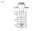
図2は、上記映像入力部13,14の具体的構成を示すブロック図である。ここでは、映像入力部13を代表して説明する。
映像入力部13の入力端子21に入力されるビデオ信号は、エンコーダ22で素材データにエンコードされてデータバッファ23に格納される。このデータバッファ23に格納された素材データは、誤り検出符号付加部24により例えばフレーム単位やGOP単位、任意のデータサイズ単位で誤り検出符号が付加されてストレージコントローラ12に出力される。また、入力端子25には、同期信号が入力される。FIG. 2 is a block diagram showing a specific configuration of the
The video signal input to the input terminal 21 of the
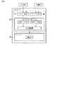
図3は、上記ストレージコントローラ12の具体的構成を示すブロック図である。 FIG. 3 is a block diagram showing a specific configuration of the
現用系の映像入力部13から出力された素材データは、データバッファ(A)31に格納された後、誤り検査部32により誤り検出符号の検査が行われた後、ストレージ11に収録される。また、予備系の映像入力部14から出力された素材データは、データバッファ(B)33に格納された後、誤り検査部32により誤り検出符号の検査が行われた後、ストレージ11に収録される。 The material data output from the active
上記誤り検査部32の検査結果は、データ削除手段としてのストレージコントローラ管理部34に供給される。ストレージコントローラ管理部34は、上記誤り検査部32の検査結果に基づいて、異常がある系の素材データをストレージ11から削除する。一方、ストレージコントローラ管理部34は、上記誤り検査部32の検査結果に基づいて、両系が正常である場合に、上記映像収録管理部15からの指示に従って、指定された現用系の素材データをストレージ11に残し、予備系の素材データをストレージ11から削除する。 The inspection result of the
次に、上記構成における動作について説明する。まず、以前に考えられた映像収録再生装置を例に説明する。 Next, the operation in the above configuration will be described. First, a video recording / playback apparatus conceived before will be described as an example.
(ビデオサーバの系統の二重化)
図4において、ビデオサーバA1とビデオサーバB2は等しい構成のビデオサーバである。ビデオサーバA1を現用系、ビデオサーバB2を予備系として運用することで、系統の二重化を行う。収録制御は各ビデオサーバA1,B2のエンコーダ41で入力信号をエンコードし、エンコードデータをメモリコントローラ42へ送信する。メモリコントローラ42からストレージ43の各ストレージへ素材(A)(素材(B))が記録される。素材(A)と素材(B)は等しい素材である。収録装置の二重化は、収録(エンコード)エラーが素材(A)で発生した場合に系統をビデオサーバB2を現用系、ビデオサーバA1を予備系に切り替える。(Redundant video server system)
In FIG. 4, the video server A1 and the video server B2 are video servers having the same configuration. The system is duplicated by operating the video server A1 as the active system and the video server B2 as the standby system. In recording control, the
しかしながら、上記構成では、系統内での冗長性を保つことができない。また、系統を二重化する必要があるため機器の体積・コストも二倍に増加する。 However, the above configuration cannot maintain redundancy in the system. In addition, since it is necessary to duplicate the system, the volume and cost of the equipment are doubled.
(収録素材の二重化)
図5は、一つの素材の収録で二つのエンコーダを使用し二つの素材データをストレージに保存することで二重化を行うビデオサーバである。(Duplicated recording materials)
FIG. 5 shows a video server that performs duplication by storing two material data in a storage using two encoders for recording one material.
エンコーダ51からエンコードデータをメモリコントローラ53へ送信しストレージ54へ素材(A)を記録する。同様に、エンコーダ52からエンコードデータをメモリコントローラ53へ送信しストレージ54へ素材(B)を記録することで二重化している。この場合、二つの素材をストレージに書込むためコーデックに依らない。 Encode data is transmitted from the encoder 51 to the
しかしながら、冗長性を保つために一つの素材に対し二重でデータ保存する必要がある。エンコードデータの正当性を収録時に得られないため二つの素材を保存し続ける必要がある。このためストレージ資源の消費が常に二倍になる。 However, in order to maintain redundancy, it is necessary to store data twice for one material. Since the correctness of the encoded data cannot be obtained at the time of recording, it is necessary to keep two materials. This always doubles the consumption of storage resources.
(二つの収録装置の二重化を行い、特定のデータ単位で誤り検出を記録前に行い正当性を保つ場合)
図6は、二つの収録装置の二重化を行い、特定のデータ単位で誤り検出を記録前に行うビデオサーバの構成を示すブロック図である。一つの素材の収録で二つのエンコーダ61,62を使用しGOP単位など特定のデータ単位で誤り検出符号を付加し、メモリコントローラ63などストレージの前段で誤り検出を行い正常なデータのみストレージ64に保存することで、エンコードデータの正当性を確保する。(When two recording devices are duplicated and error detection is performed in a specific data unit before recording to ensure correctness)
FIG. 6 is a block diagram showing the configuration of a video server that duplicates two recording devices and performs error detection before recording in a specific data unit. In one material recording, two encoders 61 and 62 are used to add an error detection code in a specific data unit such as a GOP unit, and error detection is performed in the previous stage of storage such as the
ところで、コーデックがClosed GOPの場合はGOP単位での差替えが可能であるが、Open GOPの様に連続性を持つデータの場合はGOP単位での挿し替えができず、収録を中断するしかない。 By the way, when the codec is a Closed GOP, replacement in GOP units is possible. However, in the case of data having continuity like Open GOP, replacement is not possible in GOP units, and recording must be interrupted.
そこで、本実施形態では、ストレージ11に現用系及び予備系の素材データを収録した後に、異常のある系あるいは選択指定された系の素材データをストレージ11から削除するようにして、1台の映像収録装置の収録処理のみで正当なエンコードデータをストレージ11に保存できるようにして、ストレージ資源の節約を図るようにしている。 Therefore, in this embodiment, after recording the active and standby material data in the
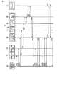
(収録処理 正常データ)
図7は、二つの映像入力部13,14からの素材データが正常である場合の収録処理を示す。系統設定は映像収録管理部15で行う。(Recording process normal data)
FIG. 7 shows a recording process when the material data from the two
映像収録管理部15は、映像入力部(A)13と映像入力部(B)14へ同時に収録制御を行う(S101,S102)。収録制御開始時にストレージコントローラ管理部34へエンコーダ(A)22を現用系、エンコーダ(B)22を予備系に指定する(S103)。映像入力部42,43でエンコード後に誤り検出符号を付加し、ストレージコントローラ12のデータバッファ(A)31へデータを転送する(D01)。同様に映像入力部(B)14でエンコード後に誤り検出符号を付加し、ストレージコントローラ12のデータバッファ(B)33へデータを転送する(D02)。 The video
データバッファ(A)31とデータバッファ(B)33に誤り検出符号の付加単位のデータが転送された後(D03/D04)、誤り検査部32で検査を行い検査結果をストレージコントローラ管理部34へ通知する(S104)。 After the data of the additional unit of the error detection code is transferred to the data buffer (A) 31 and the data buffer (B) 33 (D03 / D04), the
ストレージコントローラ管理部34は、映像収録管理部15へ誤り検査結果を通知する(S105)。検査結果が正常な場合は誤り検査部32からストレージ11へ各データを転送し(D05/D06)、ストレージ11に保存する。検査結果が正常な場合は収録終了まで繰り返す。 The storage
一方、収録終了を行なう場合、映像収録管理部15から映像入力部(A)13と映像入力部(B)14へ収録終了制御を行う(S104/S105)。続いて、映像収録管理部15からストレージコントローラ管理部34へ収録終了制御を行う(S106)。そして、ストレージコントローラ管理部34から誤り検査部32へ検査結果要求を行い(S107)、誤り検査部32からストレージコントローラ管理部34へ検査結果応答を通知する(S108)。ストレージコントローラ管理部34は検査結果応答を映像収録管理部15へ通知する(S109)。検査結果応答が正常な場合、予備系の映像入力部(B)14で収録したデータの削除制御をストレージコントローラ管理部34へ行う(S110)。 On the other hand, when the recording is ended, the recording end control is performed from the video
ストレージコントローラ管理部34は映像収録管理部15の制御により、ストレージ11へ映像入力部(B)14のデータの削除制御を行う(S111)。そして、ストレージで削除処理を実行し(S112)、削除処理結果をストレージコントローラ管理部へ通知する(S113)。ストレージコントローラ管理部34は映像収録管理部15へ素材削除処理結果を通知する(S114)。 The storage
上記処理により、素材の収録完了後、ストレージ11に保存されている素材データは一つのみになる。 With the above processing, after the material recording is completed, only one material data is stored in the
(収録処理 片系異常データ)
図8は、一つの収録系統で誤り検査部32で誤り検出が発生し異常データとなる時の収録処理を示す。(Recording processing single system abnormal data)
FIG. 8 shows recording processing when error detection occurs in the
映像収録管理部15は、映像入力部(A)13と映像入力部(B)14へ同時に収録制御を行う(S201,S202)。収録制御開始時にストレージコントローラ管理部34へエンコーダ(A)22を現用系、エンコーダ(B)22を予備系に指定する(S203)。映像入力部13,14でエンコード後に誤り検出符号を付加し、ストレージコントローラ12のデータバッファ(A)31へデータを転送する(D11)。 The video
同様に映像入力部(B)14でエンコード後に誤り検出符号を付加し、ストレージコントローラ12のデータバッファ(B)33へデータを転送する(D12)。データバッファ(A)31とデータバッファ(B)33に誤り検出符号の付加単位のデータが転送された後(D13/D14)、誤り検査部32で検査を行い検査結果をストレージコントローラ管理部34へ通知する(S204)。 Similarly, an error detection code is added after encoding by the video input unit (B) 14, and the data is transferred to the data buffer (B) 33 of the storage controller 12 (D12). After the data of the additional unit of the error detection code is transferred to the data buffer (A) 31 and the data buffer (B) 33 (D13 / D14), the
ストレージコントローラ管理部34は、映像収録管理部15へ誤り検査結果を通知する(S205)。検査結果が正常な場合は誤り検査部32からストレージ11へ各データを転送し(D15/D16)、ストレージ11に保存する。検査結果が正常な場合は繰り返す。 The storage
一方、映像入力部(B)14から転送されたデータバッファ(B)33のデータが誤り検査部32で異常データと検出された場合は、誤り検査部32からストレージコントローラ管理部34へ検査結果異常通知を行い(S204)、ストレージコントローラ管理部34は映像収録管理部15へ検査結果異常通知を行う(S205)。 On the other hand, if the data in the data buffer (B) 33 transferred from the video input unit (B) 14 is detected as abnormal data by the
映像収録管理部15は検査結果異常通知を受け取り、映像入力部(B)14とストレージコントローラ管理部34へ予備系(B系)の収録停止制御を行う(S206/S207)。ストレージコントローラ管理部34は、映像収録管理部15へ予備系((B)系)収録停止応答を行う(S208)。以降、収録処理は現用系((A)系)のみ繰り返し行う。 The video
収録処理完了時に、映像収録管理部15は映像入力部(A)13とストレージコントローラ管理部34に対し現用系((A)系)収録完了通知を行う。完了通知後、映像収録管理部15はストレージコントローラ管理部34へ予備系((B)系)収録の異常データの削除制御を行う(S211)。 When the recording process is completed, the video
ストレージコントローラ管理部34は、ストレージ11へ(B)系データ削除制御を行い、ストレージ11は削除処理を行った後に(S213)、ストレージコントローラ管理部34へ削除完了応答を行う(S214)。ストレージコントローラ管理部34は映像収録管理部15へ削除完了応答を行う(S215)。ストレージコントローラ管理部34からの削除完了応答を受け取り、映像収録管理部15は収録完了とする。 The storage
(収録処理 両系異常データ)
正常データ収録中は(収録処理 正常データ)と同様の処理を行う。異常データ発生時に発生した系統に対し収録中断制御を行う。両系から異常データ検出通知を受け取ると映像収録管理部15は収録失敗とする。(Recording processing both system abnormal data)
During normal data recording, the same processing as (recording normal data) is performed. Performs recording interruption control for the system that occurred when abnormal data occurred. When the abnormal data detection notification is received from both systems, the video
以上のように上記実施形態では、映像収録管理部15に対し例えば現用系と予備系の選択指定を行うことで、ストレージ11に現用系及び予備系の素材データを収録した後に、例えば予備系の素材データをストレージ11から削除し、現用系の素材データのみをストレージ11に残すようにしている。 As described above, in the above-described embodiment, for example, by selecting and specifying the active system and the standby system to the video
従って、両系の素材データに異常がない場合であっても、現用系の素材データのみをストレージ11に残すことで、1台の素材収録再生装置内で収録処理のみで正当なエンコードデータをストレージに保存することができ、ストレージ11の記憶容量を節約できる。 Therefore, even if there is no abnormality in the material data of both systems, only the material data of the active system is left in the
また、上記実施形態では、映像入力部13,14によるエンコード後に各系の素材データに付加される誤り検出符号を利用して、ストレージコントローラ12の誤り検査部32にて現用系及び予備系それぞれの素材データのデータ品質をチェックするようにし、異常な系の素材データをストレージ11から削除するようにしている。 In the above-described embodiment, the
従って、ストレージ11から素材データの再生処理を行うことなく、エンコードデータのまま異常があるか否かをチェックでき、これにより正常な系の素材データのみをストレージ11に残すことができる。 Therefore, it is possible to check whether or not there is an abnormality in the encoded data without performing reproduction processing of the material data from the
さらに、上記実施形態では、フレーム単位またはGOP(Group of Pictures)単位または任意のデータサイズ単位で、現用系及び予備系それぞれの素材データに対し誤り検出符号を付加するようにしているので、各系の素材データがオープンGOP構造をとる場合であっても、エンコードデータのまま異常があるか否かをチェックでき、これによりコーデックに依存することなく正常な系の素材データのみをストレージ11に残すことができる。 Further, in the above embodiment, since error detection codes are added to the material data of the active system and the standby system in units of frames, GOPs (Group of Pictures) or arbitrary data sizes, each system Even if the material data has an open GOP structure, it can be checked whether there is an abnormality in the encoded data, so that only normal system material data is left in the
なお、上記実施形態では、誤り検出符号を利用して両系のデータ品質のチェックを行う例について説明したが、誤り検出符号以外に、映像入力部13、14の出力データからデータ品質を検出するものであってもよい。 In the above-described embodiment, the example in which the data quality of both systems is checked using the error detection code has been described. However, in addition to the error detection code, the data quality is detected from the output data of the
なお、実施段階ではその要旨を逸脱しない範囲で構成要素を変形して具体化できる。また、上記実施形態に開示されている複数の構成要素の適宜な組み合わせにより、種々の発明を形成できる。例えば、実施形態に示される全構成要素から幾つかの構成要素を削除してもよい。 In the implementation stage, the constituent elements can be modified and embodied without departing from the spirit of the invention. In addition, various inventions can be formed by appropriately combining a plurality of components disclosed in the embodiment. For example, some components may be deleted from all the components shown in the embodiment.
11…ストレージ、12…ストレージコントローラ、13,14…映像入力部、15…映像収録管理部、22…エンコーダ、23…データバッファ、24…誤り検出符号付加部、31,33…データバッファ、32…誤り検査部、34…ストレージコントローラ管理部。 DESCRIPTION OF
Claims (7)
Translated fromJapaneseこの入力信号処理部でエンコードされた第1系及び第2系の素材データを格納する記憶部と、
この記憶部の収録・再生を制御する記憶制御部とを具備し、
前記記憶制御部は、前記記憶部に前記第1系及び第2系の素材データを収録した後、予め決められた条件に基づいて、前記第1系及び第2系の素材データのうちいずれか1つを前記記憶部から削除するデータ削除手段を備えたことを特徴とする素材収録装置。An input signal processing unit that encodes material data of the first system and the second system that have the same contents into material data, respectively;
A storage unit for storing the first-system and second-system material data encoded by the input signal processing unit;
A storage control unit for controlling recording / playback of the storage unit,
The storage control unit records the first system and second system material data in the storage unit, and then selects one of the first system and second system material data based on a predetermined condition. A material recording apparatus comprising data deletion means for deleting one from the storage unit.
前記データ削除手段は、前記条件の判断に、前記検出手段の検出結果を用いることを特徴とする請求項1記載の素材収録装置。The storage control unit further includes detection means for detecting the data quality of the material data of each of the first system and the second system output from the input signal processing unit,
The material recording apparatus according to claim 1, wherein the data deletion unit uses a detection result of the detection unit to determine the condition.
前記記憶制御部の検出手段は、前記入力信号処理部から出力される第1系及び第2系それぞれの素材データに付加される誤り検出符号を検査することで、誤り検出を行うことを特徴とする請求項3記載の素材収録装置。The input signal processing unit includes error detection code adding means for adding an error detection code in a specific data unit to the material data of the first system and the second system,
The detection means of the storage control unit performs error detection by checking an error detection code added to the material data of each of the first system and the second system output from the input signal processing unit. The material recording device according to claim 3.
このエンコードされた第1系及び第2系の素材データをそれぞれ記憶部に収録し、
前記記憶部に前記第1系及び第2系の素材データを収録した後、予め決められた条件に基づいて、前記第1系及び第2系の素材データのうちいずれか1つを前記記憶部から削除するようにしたことを特徴とする素材収録方法。Encode the first and second material signals that have the same contents into the material data,
The encoded material data of the first system and the second system are recorded in the storage unit,
After recording the first-system and second-system material data in the storage unit, the storage unit stores any one of the first-system and second-system material data based on a predetermined condition. The material recording method characterized by deleting from.
Priority Applications (4)
| Application Number | Priority Date | Filing Date | Title |
|---|---|---|---|
| JP2010061530AJP2011199414A (en) | 2010-03-17 | 2010-03-17 | Material recording device and material recording method |
| US13/019,516US9218238B2 (en) | 2010-03-17 | 2011-02-02 | Contents data recording apparatus and contents data recording method |
| KR20110016715AKR101485626B1 (en) | 2010-03-17 | 2011-02-24 | Content recording apparatus and content recording method |
| KR1020140030921AKR20140059765A (en) | 2010-03-17 | 2014-03-17 | Content recording apparatus and content recording method |
Applications Claiming Priority (1)
| Application Number | Priority Date | Filing Date | Title |
|---|---|---|---|
| JP2010061530AJP2011199414A (en) | 2010-03-17 | 2010-03-17 | Material recording device and material recording method |
Publications (1)
| Publication Number | Publication Date |
|---|---|
| JP2011199414Atrue JP2011199414A (en) | 2011-10-06 |
Family
ID=44648177
Family Applications (1)
| Application Number | Title | Priority Date | Filing Date |
|---|---|---|---|
| JP2010061530APendingJP2011199414A (en) | 2010-03-17 | 2010-03-17 | Material recording device and material recording method |
Country Status (3)
| Country | Link |
|---|---|
| US (1) | US9218238B2 (en) |
| JP (1) | JP2011199414A (en) |
| KR (2) | KR101485626B1 (en) |
Cited By (3)
| Publication number | Priority date | Publication date | Assignee | Title |
|---|---|---|---|---|
| JP2019057805A (en)* | 2017-09-20 | 2019-04-11 | 株式会社東芝 | Video recording apparatus and video recording method |
| KR102323882B1 (en)* | 2021-04-06 | 2021-11-09 | (주)매트릭스미디어 | A digital broadcasting system with real-time fault management |
| KR102323890B1 (en)* | 2021-04-06 | 2021-11-09 | (주)매트릭스미디어 | A signal processing device with channel path-based fault detection function |
Families Citing this family (1)
| Publication number | Priority date | Publication date | Assignee | Title |
|---|---|---|---|---|
| CN112148512B (en)* | 2019-06-27 | 2024-07-12 | 腾讯科技(深圳)有限公司 | Content library management method, device, equipment and storage medium |
Citations (1)
| Publication number | Priority date | Publication date | Assignee | Title |
|---|---|---|---|---|
| JP2006245867A (en)* | 2005-03-02 | 2006-09-14 | D & M Holdings Inc | Image recording reproducer and method for recording image |
Family Cites Families (26)
| Publication number | Priority date | Publication date | Assignee | Title |
|---|---|---|---|---|
| JPH0676491A (en) | 1992-06-25 | 1994-03-18 | Matsushita Electric Ind Co Ltd | Information recording / reproducing device |
| TW323029U (en)* | 1993-06-30 | 1997-12-11 | Victor Company Of Japan Co Ltd | Processing system for digital video signal |
| US5978029A (en)* | 1997-10-10 | 1999-11-02 | International Business Machines Corporation | Real-time encoding of video sequence employing two encoders and statistical analysis |
| JP3788677B2 (en)* | 1997-11-14 | 2006-06-21 | 富士通株式会社 | CONTINUOUS RECORDING SYSTEM AND METHOD, AND COMPUTER-READABLE RECORDING MEDIUM CONTAINING LONG TIME RECORDING PROGRAM |
| JPH11316655A (en) | 1997-12-05 | 1999-11-16 | Sony Corp | Device and method for recording and reproducing data, and av server |
| US6304991B1 (en)* | 1998-12-04 | 2001-10-16 | Qualcomm Incorporated | Turbo code interleaver using linear congruential sequence |
| US7072393B2 (en)* | 2001-06-25 | 2006-07-04 | International Business Machines Corporation | Multiple parallel encoders and statistical analysis thereof for encoding a video sequence |
| JP3993035B2 (en)* | 2001-07-19 | 2007-10-17 | 松下電器産業株式会社 | Data recording method, recording medium, and reproducing apparatus |
| JP2004356673A (en)* | 2003-05-26 | 2004-12-16 | Sony Corp | Motion vector detecting method and image processing apparatus using the method |
| US7627842B1 (en)* | 2003-06-03 | 2009-12-01 | Cadence Design Systems, Inc. | Method and system for verification of circuits with encoded signals |
| US7533325B2 (en)* | 2003-07-14 | 2009-05-12 | International Business Machines Corporation | Anamorphic codes |
| JP4559935B2 (en)* | 2005-08-25 | 2010-10-13 | 株式会社東芝 | Image storage apparatus and method |
| US8879856B2 (en)* | 2005-09-27 | 2014-11-04 | Qualcomm Incorporated | Content driven transcoder that orchestrates multimedia transcoding using content information |
| JP4231084B2 (en) | 2006-07-20 | 2009-02-25 | 株式会社東芝 | Content recording system, recording device used in this system, and recording control method |
| CN101536534B (en)* | 2006-10-30 | 2011-07-06 | 皇家飞利浦电子股份有限公司 | Video depth map alignment |
| CN101601302B (en)* | 2007-01-31 | 2012-07-04 | 汤姆森特许公司 | Method and apparatus for automatically categorizing potential shot and scene detection information |
| TW200837551A (en)* | 2007-03-02 | 2008-09-16 | A Data Technology Co Ltd | Storage device capable of cooperating to adjust reliability, method for establishing and input data thereof |
| KR100793286B1 (en)* | 2007-05-02 | 2008-01-10 | 주식회사 코아로직 | Digital image codec with low use of buffer memory and its control method |
| KR101409769B1 (en)* | 2007-08-01 | 2014-06-19 | 삼성전자주식회사 | Apparatus and method for processing image |
| US8077772B2 (en)* | 2007-11-09 | 2011-12-13 | Cisco Technology, Inc. | Coding background blocks in video coding that includes coding as skipped |
| JP2009238320A (en)* | 2008-03-27 | 2009-10-15 | Fujitsu Ltd | Storage device and storage method |
| US20110085551A1 (en)* | 2008-06-17 | 2011-04-14 | Avinash Sridhar | Staggercasting method and apparatus using type of service (tos) information |
| WO2009158726A1 (en)* | 2008-06-27 | 2009-12-30 | Walters Clifford A | Compact camera-mountable video encoder, studio rack-mountable video encoder, configuration device, and broadcasting network utilizing the same |
| JP4719802B2 (en)* | 2009-03-09 | 2011-07-06 | 富士通株式会社 | Storage management device, storage management method and storage system |
| US8301948B2 (en)* | 2009-08-10 | 2012-10-30 | Hitachi Global Storage Technologies Netherlands B.V. | Storage device with adaptive error-correcting code for improved areal efficiency |
| US9131278B2 (en)* | 2009-11-23 | 2015-09-08 | At&T Intellectual Property I, Lp | System and method for layered delivery of media content quality |
- 2010
- 2010-03-17JPJP2010061530Apatent/JP2011199414A/enactivePending
- 2011
- 2011-02-02USUS13/019,516patent/US9218238B2/ennot_activeExpired - Fee Related
- 2011-02-24KRKR20110016715Apatent/KR101485626B1/ennot_activeExpired - Fee Related
- 2014
- 2014-03-17KRKR1020140030921Apatent/KR20140059765A/ennot_activeWithdrawn
Patent Citations (1)
| Publication number | Priority date | Publication date | Assignee | Title |
|---|---|---|---|---|
| JP2006245867A (en)* | 2005-03-02 | 2006-09-14 | D & M Holdings Inc | Image recording reproducer and method for recording image |
Cited By (3)
| Publication number | Priority date | Publication date | Assignee | Title |
|---|---|---|---|---|
| JP2019057805A (en)* | 2017-09-20 | 2019-04-11 | 株式会社東芝 | Video recording apparatus and video recording method |
| KR102323882B1 (en)* | 2021-04-06 | 2021-11-09 | (주)매트릭스미디어 | A digital broadcasting system with real-time fault management |
| KR102323890B1 (en)* | 2021-04-06 | 2021-11-09 | (주)매트릭스미디어 | A signal processing device with channel path-based fault detection function |
Also Published As
| Publication number | Publication date |
|---|---|
| KR101485626B1 (en) | 2015-01-22 |
| US9218238B2 (en) | 2015-12-22 |
| KR20140059765A (en) | 2014-05-16 |
| US20110231714A1 (en) | 2011-09-22 |
| KR20110104878A (en) | 2011-09-23 |
Similar Documents
| Publication | Publication Date | Title |
|---|---|---|
| JP5450545B2 (en) | Server device | |
| US9081751B2 (en) | Video server and rebuild processing control method | |
| JP2011199414A (en) | Material recording device and material recording method | |
| JP4231084B2 (en) | Content recording system, recording device used in this system, and recording control method | |
| US7904650B2 (en) | Data storage apparatus and data reading method | |
| JP2014059659A (en) | Video recording/reproduction device and rebuild resumption method | |
| JP2014130657A (en) | Video recording device and monitoring camera system | |
| JP2010220183A (en) | Delivery system | |
| JP2021016080A (en) | Image/sound control device, image/sound processing device, image/sound control method, and image/sound control program | |
| CN113163270B (en) | Method and system for repairing video signal | |
| JP5170794B2 (en) | Storage system and failover control method | |
| JP4822884B2 (en) | Server apparatus, recording medium abnormality detection method and recording medium abnormality detection program | |
| JP2012073773A (en) | Storage processor and fail-over control method | |
| JP4157884B2 (en) | Recording / playback device | |
| JPH10271077A (en) | Multi-channel broadcast system | |
| JPWO2017208377A1 (en) | Log data acquisition apparatus and log data acquisition method | |
| JP2008187246A (en) | Video material transfer system and video material transfer method | |
| JP5161464B2 (en) | Broadcast material processing equipment | |
| JP2010141840A (en) | Material transmission system | |
| JP2018060366A (en) | Record system, storage device and program for camera | |
| CN1851816B (en) | Information processing apparatus and method | |
| JP2011035836A (en) | Apparatus and method for recording video | |
| JP2004311019A (en) | Recording and playback device | |
| JP2013186754A (en) | Video server device and its failure diagnosis method | |
| JP2011250324A (en) | Material server and material processing method |
Legal Events
| Date | Code | Title | Description |
|---|---|---|---|
| A977 | Report on retrieval | Free format text:JAPANESE INTERMEDIATE CODE: A971007 Effective date:20111212 | |
| A131 | Notification of reasons for refusal | Free format text:JAPANESE INTERMEDIATE CODE: A131 Effective date:20120117 | |
| A521 | Written amendment | Free format text:JAPANESE INTERMEDIATE CODE: A523 Effective date:20120316 | |
| A02 | Decision of refusal | Free format text:JAPANESE INTERMEDIATE CODE: A02 Effective date:20120529 |