Movatterモバイル変換


[0]ホーム

URL:


JP2011199317A - Stage equipment and exposure device, and method of manufacturing device - Google Patents

Stage equipment and exposure device, and method of manufacturing device
Download PDF

Info

Publication number
JP2011199317A
JP2011199317AJP2011142126AJP2011142126AJP2011199317AJP 2011199317 AJP2011199317 AJP 2011199317AJP 2011142126 AJP2011142126 AJP 2011142126AJP 2011142126 AJP2011142126 AJP 2011142126AJP 2011199317 AJP2011199317 AJP 2011199317A
Authority
JP
Japan
Prior art keywords
stage
axis
drive
along
moving
Prior art date
Legal status (The legal status is an assumption and is not a legal conclusion. Google has not performed a legal analysis and makes no representation as to the accuracy of the status listed.)
Pending
Application number
JP2011142126A
Other languages
Japanese (ja)
Inventor
Yoichi Arai
洋一 新井
Toshio Ueda
稔夫 上田
Andrew J Hazelton
アンドリュー・ジェイ・ヘイゼルトン
Mike Binnard
マイク・ビナード
W Thomas Novak
ダブリュ・トマス・ノヴァク
Douglas C Watson
ダグラス・シー・ワトソン
Kirk Lok
カーク・ロク
Wen-Hou Ma
ウェン−ホウ・マ
Pai-Hsueh Yang
パイ−ヒュー・ヤン
Ting-Chien Teng
ティン−チェン・テン
Bausan Yuan
バウサン・ユァン
Current Assignee (The listed assignees may be inaccurate. Google has not performed a legal analysis and makes no representation or warranty as to the accuracy of the list.)
Nikon Corp
Original Assignee
Nikon Corp
Priority date (The priority date is an assumption and is not a legal conclusion. Google has not performed a legal analysis and makes no representation as to the accuracy of the date listed.)
Filing date
Publication date
Priority claimed from US11/048,405external-prioritypatent/US7869000B2/en
Priority claimed from US11/258,249external-prioritypatent/US7417714B2/en
Application filed by Nikon CorpfiledCriticalNikon Corp
Publication of JP2011199317ApublicationCriticalpatent/JP2011199317A/en
Pendinglegal-statusCriticalCurrent

Links

Images

Landscapes

Abstract

Translated fromJapanese

【課題】物体を精密に位置決めする。
【解決手段】互いに交差する第1軸、第2軸及び第3軸に沿って物体を移動させる。第1部材と、第1軸に沿って第1部材を移動させる第1移動装置と、物体を保持する第2部材と、第1軸、第2軸及び第3軸に沿って、第1部材に対して第2部材を移動させる第2移動装置と、第1部材に設けられて、第2部材を、第2部材が第1部材に対して第1軸及び第2軸に沿った方向に移動可能に支持するベアリング部材と、を有する。第2移動装置は、コイル部材と、コイル部材と協働して第2部材を第1部材に対して第3軸に沿って移動させる駆動力を発生させる磁性部材とを有する。コイル部材と磁性部材とが第1部材に設けられている。
【選択図】図1
To accurately position an object.
An object is moved along a first axis, a second axis, and a third axis that intersect each other. A first member, a first moving device that moves the first member along the first axis, a second member that holds the object, and the first member along the first, second, and third axes A second moving device that moves the second member relative to the first member, and the second member is moved in a direction along the first axis and the second axis with respect to the first member. And a bearing member that is movably supported. The second moving device includes a coil member and a magnetic member that generates a driving force for moving the second member relative to the first member along the third axis in cooperation with the coil member. A coil member and a magnetic member are provided on the first member.
[Selection] Figure 1

Description

Translated fromJapanese

本出願は、2005年1月31日に出願され係属中である米国特許出願第11/048,405号(軽量精密ステージと低伝播性とを有するステージ装置)の一部係属出願である。また、本出願は、2004年11月2日に出願された米国仮出願第60/624,385号(精密ステージ構造)、2004年11月4日に出願された米国仮出願第60/625,699号(Zアクチュエータ)、及び、2005年1月28日に出願された米国仮出願第60/647,901号(精密ステージZアクチュエータ装置及び方法)、に基づく優先権を主張する。許容される範囲内において、上記の米国特許出願第11/048,405号、及び米国仮出願第60/624,385号、60/625,699号、及び、60/647,901号を本出願に援用する。  This application is a partially pending application of US patent application Ser. No. 11 / 048,405 (stage apparatus having a lightweight precision stage and low propagation properties) filed on Jan. 31, 2005 and pending. This application is also related to US Provisional Application No. 60 / 624,385 (Precision Stage Structure) filed on November 2, 2004, US Provisional Application No. 60/625, filed on November 4, 2004. 699 (Z Actuator) and US Provisional Application No. 60 / 647,901 (Precision Stage Z Actuator Device and Method) filed Jan. 28, 2005. To the extent permitted, US patent application Ser. No. 11 / 048,405 and US Provisional Applications Nos. 60 / 624,385, 60 / 625,699, and 60 / 647,901 are hereby filed. Incorporated into.

半導体製造用の露光装置は、一般に、半導体製造工程において、レチクルの像を半導体ウエハに転写するのに使用される。通常、露光装置は、照明源、レチクルを位置決めするレチクルステージ装置、光学機器、半導体ウエハを位置決めするウエハステージ装置、測定システム、及び制御システムを有する。  An exposure apparatus for manufacturing a semiconductor is generally used to transfer an image of a reticle to a semiconductor wafer in a semiconductor manufacturing process. In general, an exposure apparatus includes an illumination source, a reticle stage apparatus that positions a reticle, an optical apparatus, a wafer stage apparatus that positions a semiconductor wafer, a measurement system, and a control system.

一般的なステージ装置は、粗動ステージ、粗動ステージを駆動する粗動装置、精密ステージ、精密ステージを駆動する精密駆動装置を有する。この構成において、測定システムは、精密ステージの位置を常にモニターする。  A general stage apparatus has a coarse movement stage, a coarse movement apparatus that drives the coarse movement stage, a precision stage, and a precision drive apparatus that drives the precision stage. In this configuration, the measurement system constantly monitors the position of the precision stage.

ステージ構造において、地表あるいは周辺からの振動及び外乱が粗動ステージに伝わり、その後、精密ステージに伝わることがある。これは、精密ステージの位置決めエラーを引き起こす可能性がある。レチクルからウエハに転写される像の大きさや像形状は、微小である。こうしたことから、ウエハ及びレチクルの精密な位置決めは、高密度の半導体ウエハの製造にとって極めて重要である。  In the stage structure, vibrations and disturbances from the ground surface or the periphery may be transmitted to the coarse motion stage and then to the precision stage. This can cause precision stage positioning errors. The size and shape of the image transferred from the reticle to the wafer are very small. For this reason, precise positioning of the wafer and reticle is critical for the production of high density semiconductor wafers.

本発明は、互いに交差する第1軸、第2軸及び第3軸に沿って物体を移動させるステージ装置に関する。ステージ装置は、第1部材と、前記第1軸に沿って前記第1部材を移動させる第1移動装置と、前記物体を保持する第2部材と、前記第1軸、前記第2軸及び前記第3軸に沿って、前記第1部材に対して前記第2部材を移動させる第2移動装置と、前記第1部材に設けられて、前記第2部材を、該第2部材が前記第1部材に対して前記第1軸及び前記第2軸に沿った方向に移動可能に支持するベアリング部材と、を有する。前記第2移動装置は、コイル部材と該コイル部材と協働して前記第2部材を前記第1部材に対して前記第3軸に沿って移動させる駆動力を発生させる磁性部材とを有し、前記コイル部材と前記磁性部材とが前記第1部材に設けられている。  The present invention relates to a stage apparatus that moves an object along a first axis, a second axis, and a third axis that intersect each other. The stage device includes a first member, a first moving device that moves the first member along the first axis, a second member that holds the object, the first axis, the second axis, and the A second moving device configured to move the second member relative to the first member along a third axis; and the second member provided on the first member, wherein the second member is the first member. And a bearing member that supports the member so as to be movable in a direction along the first axis and the second axis. The second moving device includes a coil member and a magnetic member that cooperates with the coil member to generate a driving force for moving the second member along the third axis with respect to the first member. The coil member and the magnetic member are provided on the first member.

また、本発明に係る露光装置は、先に記載のステージ装置を有するものである。  An exposure apparatus according to the present invention includes the stage apparatus described above.

また、本発明に係るデバイス製造方法は、基板を用意する工程と、先に記載の露光装置を用いて前記基板上に像を形成する工程とを有するものである。  The device manufacturing method according to the present invention includes a step of preparing a substrate and a step of forming an image on the substrate using the exposure apparatus described above.

本発明の特徴を有する露光装置の概略図である。It is the schematic of the exposure apparatus which has the characteristics of this invention.本発明の特徴を有するステージ装置の一実施形態の模式的な側面図である。It is a typical side view of one Embodiment of the stage apparatus which has the characteristics of this invention.図2Aのステージ装置の部分的な斜視図である。It is a partial perspective view of the stage apparatus of FIG. 2A.図2Aのステージ装置の別の部分的な斜視図である。FIG. 2B is another partial perspective view of the stage apparatus of FIG. 2A.図2Cのステージ装置の部分的な正面図である。It is a partial front view of the stage apparatus of FIG. 2C.ステージ装置の一部及びワークピースの上からの斜視図である。It is a perspective view from above of a part of stage device and a workpiece.本発明の特徴を有するミラーの斜視図である。It is a perspective view of the mirror which has the characteristics of this invention.図3Bのミラーの上面図である。3B is a top view of the mirror of FIG. 3B. FIG.図3Cのミラーの部分的な上面図である。FIG. 3C is a partial top view of the mirror of FIG. 3C.ステージ装置の部分的な下からの斜視図である。It is a perspective view from the lower part of a stage apparatus.ステージ装置の部分的な模式図である。It is a partial schematic diagram of a stage apparatus.X駆動機の部分的な斜視図である。It is a partial perspective view of X drive machine.テーブルの分解斜視図である。It is a disassembled perspective view of a table.別のテーブルの分解斜視図である。It is a disassembled perspective view of another table.テーブルのさらに別の実施形態の分解斜視図である。It is a disassembled perspective view of another embodiment of a table.Z駆動機の斜視図である。It is a perspective view of a Z drive machine.Z駆動機の部分的な断面斜視図である。It is a partial section perspective view of a Z drive machine.Z駆動機の部分的な断面平面図である。It is a partial cross-sectional top view of Z drive machine.Z駆動機の部分的な拡大平面図である。It is a partial enlarged plan view of a Z drive machine.ステージ装置の部分的な模式図である。It is a partial schematic diagram of a stage apparatus.ステージ装置の別の実施形態の上からの部分的な斜視図である。FIG. 6 is a partial perspective view from above of another embodiment of a stage apparatus.図6Aのステージ装置の下からの部分的な斜視図である。FIG. 6B is a partial perspective view from below of the stage apparatus of FIG. 6A.ステージ装置の別の実施形態の上からの部分的な斜視図である。FIG. 6 is a partial perspective view from above of another embodiment of a stage apparatus.図7Aのステージ装置の横からの部分的な斜視図である。It is a partial perspective view from the side of the stage apparatus of FIG. 7A.ステージ装置の別の実施形態の部分的な模式図である。It is a partial schematic diagram of another embodiment of a stage apparatus.本発明の特徴を有するステージ装置の部分的な模式図である。It is a partial schematic diagram of the stage apparatus which has the characteristics of this invention.図9Aのステージ装置の一部の制御機能を示す模式的なブロック図である。FIG. 9B is a schematic block diagram showing some control functions of the stage apparatus of FIG. 9A.伝播性補償に関するシミュレートデータを示すグラフである。It is a graph which shows the simulated data regarding propagation property compensation.伝播性補償に関するシミュレートデータを示すグラフである。It is a graph which shows the simulated data regarding propagation property compensation.伝播性補償に関するシミュレートデータを示すグラフである。It is a graph which shows the simulated data regarding propagation property compensation.剛性補償の効果を示すグラフである。It is a graph which shows the effect of rigidity compensation.剛性補償の効果を示すグラフである。It is a graph which shows the effect of rigidity compensation.本発明の特徴を有するステージ装置の別の実施形態の部分的な模式図である。It is a partial schematic diagram of another embodiment of the stage apparatus which has the characteristics of this invention.本発明の特徴を有するステージ装置の別の実施形態の部分的な模式図である。It is a partial schematic diagram of another embodiment of the stage apparatus which has the characteristics of this invention.本発明の特徴を有するステージ装置の別の実施形態の部分的な模式図である。It is a partial schematic diagram of another embodiment of the stage apparatus which has the characteristics of this invention.本発明に係るデバイス製造方法のプロセスを説明するためのフローチャートである。It is a flowchart for demonstrating the process of the device manufacturing method which concerns on this invention.デバイス処理の詳細を説明するためのフローチャートである。It is a flowchart for demonstrating the detail of a device process.

本発明の特徴は、発明内容はもちろん、その構成及び動作のいずれも、同種の特徴が同種の部分として言及された、添付の図面及び以下の説明から最良に理解される。The features of the present invention, as well as the content of the invention, as well as its construction and operation, are best understood from the accompanying drawings and the following description, in which like features are referred to as like parts.

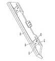
図1は精密機器、すなわち本発明の特徴を有する露光装置10の概略図である。露光装置10は、装置フレーム12、照明系(照射装置)14、光学機器16、レチクルステージ装置18、ウエハステージ装置20、測定システム22、及び制御システム24を備える。露光装置10の構成のデザインは、露光装置10の設計要求に応じて様々に変更可能である。  FIG. 1 is a schematic view of a precision instrument, that is, anexposure apparatus 10 having features of the present invention. Theexposure apparatus 10 includes anapparatus frame 12, an illumination system (irradiation apparatus) 14, anoptical device 16, areticle stage apparatus 18, awafer stage apparatus 20, ameasurement system 22, and acontrol system 24. The design of the configuration of theexposure apparatus 10 can be variously changed according to the design requirements of theexposure apparatus 10.

複数の図において、X軸、X軸に直交するY軸、及び、X軸及びY軸に直交するZ軸が設定された座標系を採用している。なお、これらの軸は、第1、第2、及び第3軸としても参照される。  In a plurality of drawings, a coordinate system in which an X axis, a Y axis orthogonal to the X axis, and a Z axis orthogonal to the X axis and the Y axis are set is employed. These axes are also referred to as the first, second, and third axes.

露光装置10は、集積回路のパターン(不図示)を、レチクル26から半導体ウエハ200(図2B参照)上に転写するリソグラフィ装置として特に好ましく用いられる。露光装置10は、地面、土台、床、あるいは他の支持構造物などの、搭載ベース30に搭載されている。  Theexposure apparatus 10 is particularly preferably used as a lithography apparatus that transfers an integrated circuit pattern (not shown) from areticle 26 onto a semiconductor wafer 200 (see FIG. 2B). Theexposure apparatus 10 is mounted on a mountingbase 30 such as the ground, base, floor, or other support structure.

リソグラフィ装置としては、様々なタイプがある。例えば、露光装置10は、レチクル26とウエハ200とを同期移動させながら、レチクル26からウエハ200にパターン露光する、スキャニング型のフォトリソグラフィシステムとして用いられる。スキャニング型のリソグラフィ装置においては、レチクルステージ装置18によって光学機器16の光軸に対して垂直にレチクル26が移動され、また、ウエハステージ装置20によって光学機器16の光軸に対して垂直にウエハ200が移動される。レチクル26とウエハ200との同期移動の間に、レチクル26とウエハ200の走査が行われる。  There are various types of lithographic apparatus. For example, theexposure apparatus 10 is used as a scanning photolithography system that exposes a pattern from thereticle 26 onto thewafer 200 while moving thereticle 26 and thewafer 200 synchronously. In the scanning type lithographic apparatus, thereticle 26 is moved perpendicularly to the optical axis of theoptical instrument 16 by thereticle stage apparatus 18, and thewafer 200 is perpendicular to the optical axis of theoptical instrument 16 by thewafer stage apparatus 20. Is moved. While thereticle 26 and thewafer 200 are synchronously moved, thereticle 26 and thewafer 200 are scanned.

また、露光装置10は、レチクル26とウエハ200とが静止した状態で、レチクル26を露光する、ステップ・アンド・リピート型のフォトグラフィシステムとして用いることもできる。ステップ・アンド・リピートの工程では、1つのフィールドの露光中において、レチクル26及び光学機器16に対して一定位置にウエハ200がある。その後、連続した複数の露光ステップの間に、光学機器16の光軸に対して垂直に、ウエハステージ装置20とともに一定速度でウエハが動かされ、ウエハ200における次のフィールドが光学機器16及びレチクル26に対する露光位置に配置される。このプロセスの後、レチクル26上の像がウエハ200の前記フィールドに順次的に露光され、その後、ウエハ200の次のフィールドが光学機器16及びレチクル26に対して位置決めされる。  Theexposure apparatus 10 can also be used as a step-and-repeat photographic system that exposes thereticle 26 while thereticle 26 and thewafer 200 are stationary. In the step-and-repeat process, thewafer 200 is in a fixed position with respect to thereticle 26 and theoptical device 16 during exposure of one field. Thereafter, during a plurality of successive exposure steps, the wafer is moved at a constant speed together with thewafer stage device 20 perpendicular to the optical axis of theoptical device 16, and the next field in thewafer 200 is moved to theoptical device 16 and thereticle 26. Is positioned at the exposure position. After this process, the image on thereticle 26 is sequentially exposed to the field of thewafer 200 and then the next field of thewafer 200 is positioned relative to theoptical instrument 16 and thereticle 26.

なお、ここで提供される露光装置10の用途は、半導体製造用のフォトリソグラフィシステムに限定されない。例えば、露光装置10は、液晶ディスプレイデバイスのパターンを矩形のガラスプレートに露光するLCDフォトリソグラフィシステム、あるいは、薄膜磁気ヘッド製造用のフォトリソグラフィシステムとしても使用可能である。さらに、本発明は、レンズ機器を介することなく、マスクを基板に近づけてマスクパターンをマスクから基板に露光するプロキシミティ方式のフォトリソグラフィシステムにも適用可能である。  The application of theexposure apparatus 10 provided here is not limited to a photolithography system for semiconductor manufacturing. For example, theexposure apparatus 10 can be used as an LCD photolithography system that exposes a pattern of a liquid crystal display device onto a rectangular glass plate, or a photolithography system for manufacturing a thin film magnetic head. Furthermore, the present invention can also be applied to a proximity-type photolithography system that exposes a mask pattern from the mask to the substrate by bringing the mask close to the substrate without using a lens device.

装置フレーム12は、剛体であり、露光装置10の構成部品を支持する。図1に示す装置フレーム12は、搭載ベース30上で、レチクルステージ装置18、光学機器16、及び照明系14を支持する。  Theapparatus frame 12 is a rigid body and supports the components of theexposure apparatus 10. Theapparatus frame 12 shown in FIG. 1 supports thereticle stage device 18, theoptical device 16, and theillumination system 14 on the mountingbase 30.

照明系14は、光源32、及び照明光学機器34含む。光源32は、光エネルギーのビーム(光束)を発する。照明光学機器34は、光エネルギーのビームを、光源32から光学機器16に導く。ビームは、レチクル26の異なる複数の部分を選択的に照射し、ウエハ200を露光する。図1では、光源32がレチクルステージ装置18の上方に支持されているように描かれている。しかしながら、通常は、装置フレーム12の側部の1つに光源32が固定され、光源32からのエネルギービームが照明光学機器34によって上方のレチクルステージ装置18に導かれる。  Theillumination system 14 includes alight source 32 and illuminationoptical equipment 34. Thelight source 32 emits a light energy beam. The illuminationoptical device 34 guides a beam of light energy from thelight source 32 to theoptical device 16. The beam selectively irradiates a plurality of different portions of thereticle 26 to expose thewafer 200. In FIG. 1, thelight source 32 is depicted as being supported above thereticle stage device 18. However, normally, thelight source 32 is fixed to one of the side portions of theapparatus frame 12, and the energy beam from thelight source 32 is guided to the upperreticle stage apparatus 18 by the illuminationoptical instrument 34.

光源32は、g線源(436nm)、i線源(365nm)、KrFエキシマレーザ(248nm)、ArFエキシマレーザ(193nm)、あるいは、F2レーザ(157nm)でもよい。あるいは、光源32は、X線や電子線などの荷電粒子ビームを発してもよい。例えば、電子線を用いる場合には、電子銃の陰極(カソード)として、熱電子放射型のランタンヘキサボライト(LaB6)、あるいは、タンタル(Ta)を用いることができる。また、電子線を用いる場合には、マスクを用いる構成、マスクを用いずに直接ウエハ上にパターンを形成する構成、のいずれでもよい。  Thelight source 32 may be a g-ray source (436 nm), an i-ray source (365 nm), a KrF excimer laser (248 nm), an ArF excimer laser (193 nm), or an F2 laser (157 nm). Alternatively, thelight source 32 may emit a charged particle beam such as an X-ray or an electron beam. For example, when an electron beam is used, thermionic emission type lanthanum hexabolite (LaB6) or tantalum (Ta) can be used as the cathode of the electron gun. In the case of using an electron beam, either a configuration using a mask or a configuration in which a pattern is directly formed on a wafer without using a mask may be used.

光学機器16は、レチクル26を通過してウエハ200に向かう光を、投影及び/又は集束させる。露光装置10の設計に応じて、光学機器16は、レチクル26上の照明された像を、拡大または縮小することができる。光学機器16は、縮小システムに限定される必要はない。1倍あるいは拡大システムに対しても同様である。  Theoptical device 16 projects and / or focuses light that passes through thereticle 26 and travels toward thewafer 200. Depending on the design of theexposure apparatus 10, theoptical instrument 16 can enlarge or reduce the illuminated image on thereticle 26.Optical instrument 16 need not be limited to a reduction system. The same applies to the 1 × or enlargement system.

エキシマレーザのような遠紫外線を使用する場合には、遠紫外線を透過する石英や蛍石などのガラス材を光学機器16に用いることができる。F2タイプのレーザやX線を使用する場合には、光学機器16として反射屈折系または屈折系の光学系(レチクルも反射タイプであるのが望ましい)を採用することができ、また、電子線を使用する場合には、光学機器16として、電子レンズ及び偏向器からなる電子光学系を採用することができる。電子線が通過する光路は真空である必要がある。  When far ultraviolet rays such as excimer laser are used, a glass material such as quartz or fluorite that transmits far ultraviolet rays can be used for theoptical device 16. When an F2 type laser or X-ray is used, a catadioptric system or a refractive optical system (the reticle is also preferably a reflection type) can be adopted as theoptical device 16, and an electron beam can be used. When used, an electronic optical system composed of an electron lens and a deflector can be employed as theoptical device 16. The optical path through which the electron beam passes needs to be a vacuum.

波長が200nmまたはそれ以下の真空紫外光(VUV)を使用する露光装置においても、反射屈折系を採用することができる。光学システムの反射屈折型の例は、日本国特開平8−171054号公報及びそれに対応する米国特許第5,668,672号明細書や、日本国特開平10−20195号公報及びそれに対応する米国特許第5,835,275号明細書に開示されている。ここで、反射光学素子としては、ビームスプリッタと凹面鏡とを有する反射屈折系を採用することができる。日本国特開平8−334695号及びそれに対応する米国特許第5,689,377号明細書、日本国特開平10−3039号公報及びこれに対応する米国特許第873,605号明細書(出願日:1997年6月12日)においても、ビームスプリッタを用いずに凹面鏡を有する光学系からなる反射屈折型を採用しており、本発明に適用可能である。許容される範囲内で、上記の米国特許及び日本国特許出願公開公報の開示を援用して本文の記載の一部とする。  A catadioptric system can also be employed in an exposure apparatus that uses vacuum ultraviolet light (VUV) having a wavelength of 200 nm or less. Examples of the catadioptric type optical system include Japanese Patent Laid-Open No. 8-171054 and the corresponding US Pat. No. 5,668,672, Japanese Patent Laid-Open No. 10-20195 and the corresponding US. This is disclosed in Japanese Patent No. 5,835,275. Here, as the reflective optical element, a catadioptric system having a beam splitter and a concave mirror can be employed. Japanese Patent Laid-Open No. 8-334695 and the corresponding US Pat. No. 5,689,377, Japanese Patent Laid-Open No. 10-3039 and the corresponding US Pat. No. 873,605 (the filing date) : June 12, 1997), a catadioptric type composed of an optical system having a concave mirror is used without using a beam splitter, and is applicable to the present invention. To the extent permitted, the disclosures of the above US patents and Japanese patent application publications are incorporated herein by reference.

レチクルステージ装置18は、レチクル26を保持しかつ光学機器16及びウエハ200に対してレチクル26を位置決めする。ほぼ同様に、ウエハステージ装置20は、ウエハ200を保持しかつレチクル26における照明部分の投影像に対してウエハ200を位置決めする。  Thereticle stage device 18 holds thereticle 26 and positions thereticle 26 with respect to theoptical device 16 and thewafer 200. In substantially the same manner, thewafer stage apparatus 20 holds thewafer 200 and positions thewafer 200 with respect to the projection image of the illumination portion on thereticle 26.

さらに、フォトリソグラフィシステムにおいて、ウエハステージやマスクステージにリニアモータ(USP5,623,853またはUSP5,528,118参照)を用いる場合は、リニアモータとして、エアベアリングを用いたエア浮上型、又はローレンツ力又はリアクタンス力を用いた磁気浮上型のいずれを用いてもよい。許容される範囲内で、上記の米国特許第5,623,853号及び第5,528,118号の開示を援用して本文の記載の一部とする。  In addition, when a linear motor (see USP5,623,853 or USP5,528,118) is used for the wafer stage or mask stage in a photolithography system, the air levitation type using an air bearing or Lorentz force or reactance force is used as the linear motor. Any of the magnetic levitation types used may be used. To the extent permitted, the disclosures of US Pat. Nos. 5,623,853 and 5,528,118 are incorporated herein by reference.

また、二次元に磁石を配置した磁石ユニットと、二次元にコイルを配置した電機子ユニットとが対向した平面モータによって、ステージの1つを駆動することができる。この種の駆動システムでは、磁石ユニットと電機子ユニットとのいずれか一方がステージに接続され、他方のユニットがステージの移動面上に搭載される。  In addition, one of the stages can be driven by a planar motor in which a magnet unit in which magnets are arranged two-dimensionally and an armature unit in which coils are arranged two-dimensionally face each other. In this type of drive system, either the magnet unit or the armature unit is connected to the stage, and the other unit is mounted on the moving surface of the stage.

上記のようなステージの動きは、フォトグラフィシステムの性能に影響を及ぼす反力を発生させる可能性がある。ウエハ(基板)ステージの移動により発生する反力は、米国特許第5,528,110号及び日本国特開平8−136475号公報に記載されているような、フレーム部材を用いて機械的に床(大地)に逃がすことが可能である。また、レチクル(マスク)ステージの移動により発生する反力は、米国特許第5,874,820号及び日本国特開平8−330224号公報に記載されているような、フレーム部材を用いて機械的に大地に逃がすことが可能である。許容される範囲内において、上記の米国特許第5,528,110号、第5,874,820号、及び日本国特開平8−330224号公報の開示を援用して本文の記載の一部とする。  The movement of the stage as described above may generate a reaction force that affects the performance of the photography system. The reaction force generated by the movement of the wafer (substrate) stage is mechanically generated by using a frame member as described in US Pat. No. 5,528,110 and Japanese Patent Laid-Open No. 8-136475. It is possible to escape to (earth). The reaction force generated by the movement of the reticle (mask) stage is mechanically determined by using a frame member as described in US Pat. No. 5,874,820 and Japanese Patent Laid-Open No. 8-330224. It is possible to escape to the earth. Within the allowable range, the disclosures of the above-mentioned US Pat. Nos. 5,528,110, 5,874,820, and Japanese Patent Application Laid-Open No. 8-330224 are incorporated, To do.

測定システム22は、光学機器16あるいは他の基準に対するレチクル26及びウエハ200の移動をモニターする。この情報によって、制御システム24は、レチクルステージ装置18を制御してレチクル26を精確に位置決めすることができ、また、及びウエハステージ装置20を制御してウエハ200を精確に位置決めすることができる。例えば、測定システム22は、複数のレーザ干渉計、エンコーダ、及び/又は他の測定装置を利用することができる。  Measurement system 22 monitors movement ofreticle 26 andwafer 200 relative tooptical instrument 16 or other reference. With this information, thecontrol system 24 can control thereticle stage device 18 to accurately position thereticle 26, and can also control thewafer stage device 20 to accurately position thewafer 200. For example, themeasurement system 22 can utilize a plurality of laser interferometers, encoders, and / or other measurement devices.

制御システム24は、レチクルステージ装置18、ウエハステージ装置20、及び測定システム22に接続されている。制御システム24は、測定システム22から情報を受け取り、ステージ移動装置18,20を制御してレチクル26及びウエハ200を精確に位置決めする。制御システム24は、少なくとも1つのプロセッサ及び回路を含む構成にできる。  Thecontrol system 24 is connected to thereticle stage device 18, thewafer stage device 20, and themeasurement system 22. Thecontrol system 24 receives information from themeasurement system 22 and controls thestage moving devices 18 and 20 to accurately position thereticle 26 and thewafer 200. Thecontrol system 24 can be configured to include at least one processor and circuitry.

ここに記載される実施形態に係るフォトリソグラフィシステム(露光装置)は、添付の特許請求の範囲に挙げられた各構成要素を含む各種サブシステムを、所定の機械的精度、電気的精度、光学的精度を保つように、組み立てることで製造することができる。これら各種精度を確保するために、この組み立ての前後には、すべての光学系について、光学的精度を達成するための調整が行われる。同様に、すべての機械系及び電気系について、機械的精度及び電気的精度を達成するための調整が行われる。各種サブシステムからフォトリソグラフィシステムへの組み立て工程は、各サブシステム相互の、機械的接続、電気回路の配線接続、及び気圧回路の配管接続等を含む。この各種サブシステムからフォトリソグラフィシステムへの組み立て工程の前に、各サブシステム個々の組み立て工程があることはいうまでもない。各種サブシステムを用いてフォトリソグラフィシステムが組み立てられると、フォトリソグラフィシステム全体としての各種精度を確保するための、総合調整が行われる。なお、露光システムの製造は温度及びクリーン度等が管理されたクリーンルーム内で行うことが望ましい。  A photolithography system (exposure apparatus) according to an embodiment described herein includes various sub-systems including the constituent elements recited in the appended claims with predetermined mechanical accuracy, electrical accuracy, and optical performance. It can be manufactured by assembling so as to maintain accuracy. In order to ensure these various accuracies, adjustments to achieve optical accuracy are performed for all optical systems before and after the assembly. Similarly, adjustments are made for all mechanical and electrical systems to achieve mechanical and electrical accuracy. The assembly process from various subsystems to the photolithographic system includes mechanical connection, electrical circuit wiring connection, and pneumatic circuit piping connection between the subsystems. It goes without saying that there is an assembly process for each subsystem before the assembly process from the various subsystems to the photolithography system. When a photolithography system is assembled using various subsystems, comprehensive adjustment is performed to ensure various accuracies as the entire photolithography system. It is desirable that the exposure system be manufactured in a clean room where the temperature, cleanliness, etc. are controlled.

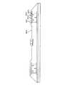
図2Aは、制御システム224の模式図であり、ワークピース200(図2B参照)の位置決めに用いるステージ装置220の一実施形態の側面図である。例えば、ステージ装置220は、図1の露光装置10におけるウエハステージ装置20として使用することができる。本実施形態において、ステージ装置220は、半導体ウエハ200の製造中に、ウエハ200(図2B参照)を位置決めするものとする。なお、ステージ装置220は、製造及び/又は検査中の他のワークピース200の移動や、電子顕微鏡におけるデバイスの移動(不図示)、あるいは、精密な測定作業中のデバイスの移動(不図示)にも使用することができる。例えば、ステージ装置220は、レチクルステージ装置18として機能するように設計されてもよい。  FIG. 2A is a schematic diagram of thecontrol system 224 and is a side view of one embodiment of astage apparatus 220 used to position the workpiece 200 (see FIG. 2B). For example, thestage apparatus 220 can be used as thewafer stage apparatus 20 in theexposure apparatus 10 of FIG. In the present embodiment, it is assumed that thestage apparatus 220 positions the wafer 200 (see FIG. 2B) during the manufacture of thesemiconductor wafer 200. Thestage apparatus 220 is used for moving anotherworkpiece 200 during manufacture and / or inspection, moving a device in an electron microscope (not shown), or moving a device during precise measurement work (not shown). Can also be used. For example,stage device 220 may be designed to function asreticle stage device 18.

本実施形態において、ステージ装置220は、ステージベース236と、第1ステージ238と、第2ステージ240と、第1移動装置242と、第2移動装置244とを有する。これらの要素のサイズ、形状、及びデザインはそれぞれ、様々に変更可能である。制御システム224は、ワークピース200を精確に位置決めするために、移動装置242,244を精密に制御する。  In the present embodiment, thestage device 220 includes astage base 236, afirst stage 238, asecond stage 240, a first movingdevice 242, and a second movingdevice 244. Each of these elements can vary in size, shape, and design. Thecontrol system 224 precisely controls the movingdevices 242 and 244 in order to accurately position theworkpiece 200.

図2Aにおいて、ステージベース236は、ステージ装置220のいくつかの構成要素を支持し、X軸に沿って、Y軸に沿って、及びZ軸周りに、第1ステージ238の移動を案内する。本実施形態において、ステージベース236は、概ね矩形形状である。  In FIG. 2A, thestage base 236 supports several components of thestage apparatus 220 and guides the movement of thefirst stage 238 along the X axis, along the Y axis, and about the Z axis. In the present embodiment, thestage base 236 has a generally rectangular shape.

第1ステージ238は、第2ステージ240の比較的大きな移動を促す、いわゆる粗動ステージである。一実施形態において、第1ステージ238は、第2ステージ240及び第2移動装置244を支持する。一実施形態において、第1ステージ238は、下方支持体251A、下方支持体251Aに固定された上方支持体251B、及び下方支持体251Aを支持するステージフレーム251Cを有する。図2Aにおいては、ステージベース236の上方でベアリング(不図示)が第1ステージ238を支持しかつ、ステージベース236に対して相対的に、X軸に沿って、Y軸に沿って、及びZ軸周りに、第1ステージ238が移動するのを許容する。ベアリングとして、例えば、真空予圧型の流体ベアリング、磁気型のベアリング、あるいはローラ型の機器が適用可能である。  Thefirst stage 238 is a so-called coarse movement stage that promotes a relatively large movement of thesecond stage 240. In one embodiment, thefirst stage 238 supports thesecond stage 240 and the second movingdevice 244. In one embodiment, thefirst stage 238 includes alower support 251A, anupper support 251B fixed to thelower support 251A, and astage frame 251C that supports thelower support 251A. In FIG. 2A, a bearing (not shown) above thestage base 236 supports thefirst stage 238 and is relative to thestage base 236 along the X axis, along the Y axis, and Z Thefirst stage 238 is allowed to move around the axis. As the bearing, for example, a vacuum preload type fluid bearing, a magnetic type bearing, or a roller type device can be applied.

第2ステージ240は、ワークピース200を保持する、いわゆる精密ステージである。第2ステージ240については、後で詳述する。  Thesecond stage 240 is a so-called precision stage that holds theworkpiece 200. Thesecond stage 240 will be described in detail later.

第1移動装置242は、ステージベース236と相対的に、第1ステージ238と、第2移動装置244の一部とを移動させる。図2Aに示す実施形態では、第1移動装置242は、3つの移動軸に対して、すなわち、X軸に沿って、Y軸に沿って、及びZ軸周りに、第1ステージ238を移動させる。また、例えば、第1移動装置242は、3未満の移動軸に対して、あるいは3を超える移動軸に対して、第1ステージ238を移動させる構成とすることもできる。第1移動装置242は、1以上の駆動機を有してもよい。  The first movingdevice 242 moves thefirst stage 238 and a part of the second movingdevice 244 relative to thestage base 236. In the embodiment shown in FIG. 2A, the first movingdevice 242 moves thefirst stage 238 with respect to three movement axes, that is, along the X axis, along the Y axis, and about the Z axis. . Further, for example, the first movingdevice 242 may be configured to move thefirst stage 238 with respect to a moving axis of less than 3 or with respect to a moving axis of more than 3. The first movingdevice 242 may have one or more driving machines.

図2Aにおいて、第1移動装置242は、左X粗動機246Lと、右X粗動機246Rと、Y粗動機246Y(想像線で示される)と、ガイドバー248とを有する。  In FIG. 2A, the first movingdevice 242 includes a left Xcoarse machine 246L, a right Xcoarse machine 246R, a Ycoarse machine 246Y (indicated by an imaginary line), and aguide bar 248.

X粗動機246L,246Rは、ガイドバー248を移動させて、X軸に沿って、Z軸周りに限定された範囲内で、ガイドバー248及び第1ステージ238を移動させ、また、Y粗動機246Yは、Y軸に沿って、ガイドバー248に対して相対的に、第1ステージ238を移動させる。Z軸周りの動きは、左X粗動機246A及び右X粗動機246Rによって発生する力の量の差を制御することによって達成される。  The X coarsemovers 246L and 246R move theguide bar 248 to move theguide bar 248 and thefirst stage 238 along the X axis within a limited range around the Z axis. 246Y moves thefirst stage 238 relative to theguide bar 248 along the Y axis. Movement about the Z axis is achieved by controlling the difference in the amount of force generated by the left X coarse machine 246A and the right Xcoarse machine 246R.

各粗動機246L,246R,246Yのデザインは、第1移動装置242の動作要求に適するように様々に変更可能である。図2Aに示す本実施形態では、各粗動機246L,246R,246Yは、第1粗動用部品250Aと、第1粗動用部品250Aと相互に作用する第2粗動用部品250Bとを有する。本実施形態において、各粗動機246L,246R,246Yは、リニアモータであり、粗動用部品250A,250Bのうちの1つが1以上の磁石を含む磁石アレイを有し、粗動用部品250B,250Aのうちの1つが1以上のコイルを含む導体アレイを有する。図2Aにおいて、各X粗動機246L,246Rの第1粗動用部品250Aが、ステージベース236に固定され、各X粗動機246L,246Rの第2粗動用部品250Bが、ガイドバー248に固定される。また、Y粗動機246Yの第1粗動用部品250Aが、ガイドバー248に固定され、Y粗動機246Yの第2粗動用部品250Bが、第1ステージ238に固定される。  The design of each of thecoarse machines 246L, 246R, and 246Y can be variously modified to suit the operation requirements of the first movingdevice 242. In the present embodiment shown in FIG. 2A, each of thecoarse motion machines 246L, 246R, and 246Y includes a firstcoarse motion component 250A and a secondcoarse motion component 250B that interacts with the firstcoarse motion component 250A. In this embodiment, each of thecoarse motion machines 246L, 246R, and 246Y is a linear motor, and one of thecoarse motion parts 250A and 250B has a magnet array including one or more magnets, and thecoarse motion parts 250B and 250A One of them has a conductor array including one or more coils. In FIG. 2A, the firstcoarse movement parts 250A of the Xcoarse movement machines 246L and 246R are fixed to thestage base 236, and the secondcoarse movement parts 250B of the Xcoarse movement machines 246L and 246R are fixed to theguide bar 248. . Further, the firstcoarse movement part 250A of the Ycoarse movement machine 246Y is fixed to theguide bar 248, and the secondcoarse movement part 250B of the Ycoarse movement machine 246Y is fixed to thefirst stage 238.

なお、粗動機246L,246R,246Yのうちの1以上のものが、ロータリモータ、ボイスコイルモータ、電磁駆動機、平面モータ、あるいは他の力を用いた駆動機のような、別タイプのモータであってもよい。  One or more of thecoarse motion machines 246L, 246R, and 246Y are different types of motors such as a rotary motor, a voice coil motor, an electromagnetic drive, a planar motor, or a drive using other force. There may be.

ガイドバー248は、Y軸に沿って、第1ステージ238の移動を案内する。ガイドバー248と第1ステージ238との間に、流体ベアリングのようなベアリング(不図示)又は磁気タイプのベアリングが配置されてもよい。別のベアリング(不図示)が、Z軸に沿ってステージベース236に対して離間したガイドバー248を支持するとともに、X軸に沿って、及びZ軸周りに、ステージベース236に対するガイドバー248の移動を可能にする。こうしたベアリングとしては、例えば、真空予圧型の流体ベアリング、磁気型のベアリング、あるいはローラ型の機器が適用可能である。  Theguide bar 248 guides the movement of thefirst stage 238 along the Y axis. A bearing (not shown) such as a fluid bearing or a magnetic type bearing may be disposed between theguide bar 248 and thefirst stage 238. Another bearing (not shown) supports theguide bar 248 spaced from thestage base 236 along the Z-axis, and theguide bar 248 relative to thestage base 236 along and around the X-axis. Allow movement. As such a bearing, for example, a vacuum preload type fluid bearing, a magnetic type bearing, or a roller type device is applicable.

第2移動装置244は、第2ステージ240及びワークピース200を移動させかつ位置決めする。図2Aにおいて、第2移動装置244は、6つの移動軸に対して、すなわち、X,Y,及びZ軸に沿って、また、X,Y,及びZ軸周りに、第1ステージ238に対して相対的に第2ステージ240を移動させる。また、例えば、第2移動装置244は、6未満の移動軸に対して、第2ステージ240を移動させる構成とすることもできる。第2移動装置244は、1以上の駆動機を有してもよい。  The second movingdevice 244 moves and positions thesecond stage 240 and theworkpiece 200. In FIG. 2A, thesecond movement device 244 is relative to thefirst stage 238 with respect to six movement axes, ie, along the X, Y, and Z axes, and around the X, Y, and Z axes. Thesecond stage 240 is relatively moved. Further, for example, the second movingdevice 244 can be configured to move thesecond stage 240 with respect to a moving axis of less than 6. The second movingdevice 244 may have one or more driving machines.

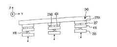
図2Bは、図2Aのステージ装置220の部分的な斜視図である。より具体的には、図2Bは、第2ステージ240と、第2移動装置244と、第1ステージ238の一部、すなわち下方支持体251A及び上方支持体251Bとを示す。  FIG. 2B is a partial perspective view of thestage apparatus 220 of FIG. 2A. More specifically, FIG. 2B shows thesecond stage 240, the second movingdevice 244, and a part of thefirst stage 238, that is, thelower support 251A and theupper support 251B.

図2Bはさらに、第2移動装置244の一実施形態の詳細を示す。具体的には、この実施形態では、第2移動装置244は、第1X駆動機252Fと、第2X駆動機252Sと、第1Y駆動機254Fと、第2Y駆動機254S(図3Aに示す)と、離間した3つのZ駆動機255(図2Bでは2つのみが示されている。)とを有する。X駆動機252F,252Sは、X軸に沿って第2ステージ240を移動させ、Y駆動機254F,254Sは、Y軸に沿って第2ステージ240を移動させ、Z駆動機255は、Z軸に沿って、またX及びY軸周りに、第2ステージ240を移動させる。X駆動機252F,252SとY駆動機254F,254Sとのいずれかは、Z軸周りの第2ステージ240の移動に用いることができる。  FIG. 2B further illustrates details of one embodiment of the secondmobile device 244. Specifically, in this embodiment, the second movingdevice 244 includes a first X drive 252F, asecond X drive 252S, afirst Y drive 254F, and a second Y drive 254S (shown in FIG. 3A). , And three spaced apart Z drives 255 (only two are shown in FIG. 2B). TheX drive units 252F and 252S move thesecond stage 240 along the X axis, theY drive units 254F and 254S move thesecond stage 240 along the Y axis, and theZ drive unit 255 moves along the Z axis. And thesecond stage 240 is moved around the X and Y axes. Any of theX drive units 252F and 252S and theY drive units 254F and 254S can be used to move thesecond stage 240 around the Z axis.

各駆動機252F,252S,254F,254S,255のデザインは、第2移動装置244の動作要求に適するように様々に変更可能である。図2Bに示す本実施形態において、各駆動機252F,252S,254F,254Sは、第1駆動用部品256Aと、この第1駆動用部品256Aと相互に作用する第2駆動用部品256Bとを有する。図2Bにおいて、X及びY駆動機252F,252S,254F,254Sのそれぞれの第1駆動用部品256Aが、第1ステージ238の上方支持体251Bに固定され、X及びY駆動機252F,252S,254F,254Sのそれぞれの第2駆動用部品256Bが、第2ステージ240に固定される。  The design of eachdrive unit 252F, 252S, 254F, 254S, 255 can be variously modified to suit the operation requirements of the second movingdevice 244. In the present embodiment shown in FIG. 2B, each of thedriving machines 252F, 252S, 254F, 254S has afirst driving component 256A and asecond driving component 256B that interacts with thefirst driving component 256A. . In FIG. 2B, thefirst driving components 256A of the X andY driving machines 252F, 252S, 254F, and 254S are fixed to theupper support 251B of thefirst stage 238, and the X andY driving machines 252F, 252S, and 254F are fixed. , 254S, thesecond driving component 256B is fixed to thesecond stage 240.

本実施形態において、各駆動機252F,252S,254F,254Sに対して、駆動用部品256A,256Bの1つが、1以上の磁石を含む磁石アレイを有し、駆動用部品256B,256Aの1つが、1以上のコイルを含む導体アレイを有する。図2Bにおいて、各駆動機252F,252S,254F,254Sに対する第1駆動用部品256Aがコイルアレイを有し、各駆動機252F,252S,254F,254Sに対する第2駆動用部品256Bが磁石アレイを有する。この構成において、第2移動装置244に電力を供給する電気配線が、第2ステージ240に接続される必要はない。しかしながら、本発明は、この構成に限定されない。また、第1駆動用部品256Aがコイルアレイを有してもよく、第2駆動用部品256Bが磁石アレイを有してもよい。  In this embodiment, for each of thedriving machines 252F, 252S, 254F, 254S, one of the drivingcomponents 256A, 256B has a magnet array including one or more magnets, and one of the drivingcomponents 256B, 256A And a conductor array including one or more coils. In FIG. 2B, thefirst drive component 256A for eachdrive unit 252F, 252S, 254F, 254S has a coil array, and thesecond drive component 256B for eachdrive unit 252F, 252S, 254F, 254S has a magnet array. . In this configuration, the electrical wiring for supplying power to the second movingdevice 244 need not be connected to thesecond stage 240. However, the present invention is not limited to this configuration. Thefirst driving component 256A may have a coil array, and thesecond driving component 256B may have a magnet array.

図2Bにおいて、各X駆動機252F,252Sは、リニアモータであり、Z駆動機255及びY駆動機254F,254Sのそれぞれは、ボイスコイルモータである。なお、駆動機252F,252S,254F,254S,255のうちの1以上のものが、ロータリモータ、電磁駆動機、平面モータ、あるいは他の力を用いた駆動機のような、別タイプのモータであってもよい。例えば、X駆動機252F,252Sのそれぞれがボイスコイルモータでもよい。  In FIG. 2B, each of theX drive units 252F and 252S is a linear motor, and each of theZ drive unit 255 and theY drive units 254F and 254S is a voice coil motor. One or more of thedriving machines 252F, 252S, 254F, 254S, 255 are other types of motors such as a rotary motor, an electromagnetic driving machine, a planar motor, or a driving machine using other force. There may be. For example, each of theX drivers 252F and 252S may be a voice coil motor.

図2Cは、図2Bにおける第1ステージ238の上方支持体251Bが取り外されたステージ装置220の斜視図であり、図2Dは、その側面図である。これらの図は、第1ステージ238の下方支持体251Aに連結されたZ駆動機255を示す。より具体的には、第1駆動用部品256Aが、下方支持体251Aに連結されている。同様に、第2駆動用部品256Bが、Zレバー408(図4Dに示す)及びZ緩衝装置410(図4Dに示す)を介して下方支持体251Aに連結されている。  2C is a perspective view of thestage device 220 with theupper support 251B of thefirst stage 238 in FIG. 2B removed, and FIG. 2D is a side view thereof. These figures show the Z drive 255 connected to thelower support 251A of thefirst stage 238. More specifically, thefirst driving component 256A is coupled to thelower support 251A. Similarly, thesecond drive component 256B is coupled to thelower support 251A via a Z lever 408 (shown in FIG. 4D) and a Z shock absorber 410 (shown in FIG. 4D).

ここで、この実施形態では、図2Dに示すように、Z軸に沿って及びX及びY軸周りに関して第1ステージ238に対して相対的な、Z駆動機255を有する第2ステージ240の移動範囲にわたり、駆動用部品256A,256B同士が互いに接しないように、X及びY駆動機252F,252S,254F,254Sにおける第1駆動用部品256Aと第2駆動用部品256Bとの間に十分な隙間258がある。  Here, in this embodiment, as shown in FIG. 2D, the movement of thesecond stage 240 having the Z drive 255 relative to thefirst stage 238 along the Z axis and about the X and Y axes. Sufficient clearance between thefirst drive component 256A and thesecond drive component 256B in the X and Y driveunits 252F, 252S, 254F, 254S so that thedrive components 256A, 256B do not touch each other over a range There are 258.

この実施形態では、ステージベアリング装置257(矢印で示す)が、第1ステージ238に対して第2ステージ240を支持する。一実施形態において、ステージベアリング装置257は、Z駆動機255に対して第2ステージ240を支持するとともに、概ねX及びY軸に沿ってかつZ軸周りに、Z駆動機255及び第1ステージ238に対して相対的な第2ステージ240の移動を可能にする。一実施形態において、ステージベアリング装置257は、流体タイプのベアリング、真空予圧型の流体ベアリング、あるいは磁気型のベアリングのような、1以上の非接触型のベアリングを有する。非接触型のベアリングを用いることにより、X及びY軸に沿った伝播性が極めて低い。換言すると、非接触型ベアリングは、第1ステージ238からの振動がX及びY軸に沿って第2ステージ240に伝わるのを抑制する。さらに、非接触ベアリングによって、第2ステージ240は、X及びY軸に沿ってかつZ軸周りに、抵抗が全く無いかそれに近い状態で移動することができる。一実施形態において、ステージベアリング装置257は、キネマティック式に第2ステージ240を支持するために、互いに離間した3つの非接触型ベアリングを有する。  In this embodiment, a stage bearing device 257 (indicated by an arrow) supports thesecond stage 240 relative to thefirst stage 238. In one embodiment, thestage bearing device 257 supports thesecond stage 240 with respect to theZ drive 255 and has theZ drive 255 and thefirst stage 238 generally along and around the X and Y axes. It is possible to move thesecond stage 240 relative to. In one embodiment, thestage bearing device 257 includes one or more non-contact type bearings, such as a fluid type bearing, a vacuum preload type fluid bearing, or a magnetic type bearing. By using a non-contact type bearing, the propagation along the X and Y axes is extremely low. In other words, the non-contact type bearing suppresses the vibration from thefirst stage 238 from being transmitted to thesecond stage 240 along the X and Y axes. Furthermore, the non-contact bearing allows thesecond stage 240 to move along the X and Y axes and around the Z axis with little or no resistance. In one embodiment, thestage bearing device 257 has three non-contact bearings spaced apart from each other to support thesecond stage 240 in a kinematic manner.

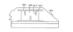
図3Aは、第2ステージ240と、図1の測定システム22に使用されるXミラー360X及びYミラー360Yと、第2移動装置244の一部と、ワークピース200とを上方から見た斜視図である。この実施形態において、第2ステージ240は、テーブル362と、テーブル362に固定されかつワークピース200を保持するチャック364とを有する。テーブル362は概ね矩形形状であり、テーブル362の右サイドには、突き出たネック状領域366Aが形成され、その領域366Aには、第1取付面366Bが形成されている。  3A is a perspective view of thesecond stage 240, theX mirror 360X and theY mirror 360Y used in themeasurement system 22 of FIG. 1, a part of the second movingdevice 244, and theworkpiece 200 as viewed from above. It is. In this embodiment, thesecond stage 240 includes a table 362 and achuck 364 that is fixed to the table 362 and holds theworkpiece 200. The table 362 has a substantially rectangular shape, and a protruding neck-shapedregion 366A is formed on the right side of the table 362, and a first mountingsurface 366B is formed in theregion 366A.

図3Aにおいて、各ミラー360X,360Yは、セラミック材料から作られるとともに概ねT字型の断面形状を有し、また、ミラー面と、互いに離れた3つの比較的薄い結合領域360Aとを有する。1以上の締め具360Fによって、結合領域360Aがテーブル362に取り付けられている。一実施形態において、各結合領域360Aは、ミラー面と各結合領域360Aとの間に配置された、1以上の細長いスロット360Sを有し、そのスロット360Sは、結合領域360Aに接した締め具360Fに起因する力と変形によって、それぞれのミラー360X,360Yの残りの部分が変形するのを抑制する。  In FIG. 3A, eachmirror 360X, 360Y is made of a ceramic material and has a generally T-shaped cross-sectional shape, and has a mirror surface and three relativelythin coupling regions 360A spaced from one another. Thecoupling region 360A is attached to the table 362 by one ormore fasteners 360F. In one embodiment, eachcoupling region 360A has one or moreelongated slots 360S disposed between the mirror surface and eachcoupling region 360A, theslot 360S being afastener 360F in contact with thecoupling region 360A. It is possible to prevent the remaining portions of therespective mirrors 360X and 360Y from being deformed by the force and deformation caused by.

図3Bはミラーの1つであるXミラー360Xの斜視図であり、図3Cはその平面図、図3Dはその部分的な平面図である。これらの図は、Xミラー360Xの残りの部分から結合領域360Aを分離する1以上のスロット360Sを示す。また、これらの図は、締め具360F(図3Aに示す)が挿入される締め孔361Aと、締め孔361Aとスロット360Sとの間で延びる結合スロット361Bとを有する、少なくとも1つの結合領域360Aを示す。一実施形態において、結合スロット361Bは、結合領域360Aに接した締め具360Fに起因する力と変形によって、Xミラー360Xの残りの部分が変形するのを抑制する。  3B is a perspective view of anX mirror 360X which is one of the mirrors, FIG. 3C is a plan view thereof, and FIG. 3D is a partial plan view thereof. These figures show one ormore slots 360S that separate thecoupling region 360A from the remainder of theX mirror 360X. These figures also show at least onecoupling region 360A having a clampinghole 361A into which afastener 360F (shown in FIG. 3A) is inserted and acoupling slot 361B extending between the clampinghole 361A and theslot 360S. Show. In one embodiment, thecoupling slot 361B prevents deformation of the remaining portion of theX mirror 360X due to forces and deformations caused by thefasteners 360F in contact with thecoupling region 360A.

図3Aに戻り、第1X駆動機252F及びY駆動機254F,254Sにおける第2駆動用部品256Bは、テーブル362の右サイドに固定されており、第2X駆動機252Sの第2駆動用部品256Bは、テーブル362の左サイドに固定されている。また、第1X駆動機252Fの第2駆動用部品256Bは、Y駆動機254F,254Sの第2駆動用部品256B同士の間に配置されている。この実施形態において、各第2駆動用部品256Bは、U字形状の駆動ハウジング368Aと、ハウジング368Aに固定されかつ互いに離れた一対の磁石アレイ368Bとを有する。一実施形態において、取付ブラケット368Cによって、第1X駆動機252F及びY駆動機254F,254Sの駆動ハウジング368Aがテーブル362に固定されている。一実施形態において、取付ブラケット368Cは、概ね梁形状である。  Returning to FIG. 3A, thesecond drive component 256B of the firstX drive unit 252F and theY drive units 254F and 254S is fixed to the right side of the table 362, and thesecond drive component 256B of the secondX drive unit 252S is The table 362 is fixed to the left side. Further, thesecond driving component 256B of the firstX driving device 252F is disposed between thesecond driving components 256B of theY driving devices 254F and 254S. In this embodiment, eachsecond drive component 256B has aU-shaped drive housing 368A and a pair ofmagnet arrays 368B fixed to thehousing 368A and spaced apart from each other. In one embodiment, thedrive housing 368A of the firstX drive unit 252F and theY drive units 254F and 254S is fixed to the table 362 by the mountingbracket 368C. In one embodiment, the mountingbracket 368C is generally beam-shaped.

図3Eは、第2ステージ240、及び第2移動装置244の一部を下から見た斜視図である。図3Eは、1つ以上のバランスウェイト370Aとテーブル362に取り付けられた1以上のストップ体370Bとを有する第2ステージ240を示している。バランスウェイト370Aは、第2ステージ240の重心(不図示)を調整するのに用いられる。したがって、バランスウェイト370Aの数、配置位置は、所望の重心が達成されるように様々に変更可能である。一実施形態において、1以上の締め具(不図示)が各バランスウェイト370A及びストップ体370Bをテーブル362に固定するために選択的に用いられる。  FIG. 3E is a perspective view of thesecond stage 240 and a part of the second movingdevice 244 as seen from below. FIG. 3E shows asecond stage 240 having one ormore balance weights 370A and one ormore stop bodies 370B attached to a table 362. Thebalance weight 370A is used to adjust the center of gravity (not shown) of thesecond stage 240. Accordingly, the number and arrangement position of thebalance weights 370A can be variously changed so that a desired center of gravity is achieved. In one embodiment, one or more fasteners (not shown) are selectively used to secure eachbalance weight 370A and stopbody 370B to the table 362.

ストップ体370Bは、第2ステージ240における安全な接触領域を形成する。この構成により、Z駆動機255(図3Eでは不図示)が停止したとき、第2ステージ240を支持するために、ストップ体370Bが第1ステージ238(図3Eでは不図示)と係合することが可能である。ストップ体370Bのデザインや数は様々に変更可能である。図3Eにおいて、第2ステージ240は、概ね矩形状の互いに離間した3つのストップ体370Bを有する。  The stop body 370 </ b> B forms a safe contact area in thesecond stage 240. With this configuration, when the Z drive 255 (not shown in FIG. 3E) stops, thestop body 370B engages with the first stage 238 (not shown in FIG. 3E) to support thesecond stage 240. Is possible. The design and number of thestop body 370B can be variously changed. In FIG. 3E, thesecond stage 240 has threestop bodies 370B that are substantially rectangular and spaced apart from each other.

図3Eにおいて、テーブル362の左サイドには、突き出た第2のネック状領域372Aが形成され、その領域372Aには、第1取付面366Bとほぼ反対側である第2取付面372Bが形成されている。第1取付面366Bは、第1表面長さ366Cと第1表面領域とを有している。同様に、第2取付面372Bは、第2表面長さ372Cと第2表面領域とを有している。特定の構成において、表面長さ366C,372C及び表面領域は、比較的小さい。非排他的実施形態において、各表面長さ366C,372Cは、約10、20、30、40、50、あるいは100mmよりも短い。また、非排他的実施形態において、各表面領域は、約5、10、20、30、40、あるいは50cm2よりも小さい。  In FIG. 3E, a protruding second neck-shapedregion 372A is formed on the left side of the table 362, and asecond mounting surface 372B that is substantially opposite to the first mountingsurface 366B is formed in theregion 372A. ing. Thefirst mounting surface 366B has afirst surface length 366C and a first surface region. Similarly, the second mountingsurface 372B has asecond surface length 372C and a second surface region. In certain configurations, thesurface lengths 366C, 372C and the surface area are relatively small. In non-exclusive embodiments, eachsurface length 366C, 372C is less than about 10, 20, 30, 40, 50, or 100 mm. Also, in non-exclusive embodiments, each surface area is less than about 5, 10, 20, 30, 40, or 50 cm2.

各X駆動機252F,252Sの駆動ハウジング368Aにおける駆動側取付面368Dは、ハウジング長さ368Eと取付側面領域とを有する。非排他的実施形態において、各ハウジング長さ368Eは、約30、50、70、100、125、150、175、あるいは200mmよりも長い。また、非排他的実施形態において、各取付側面領域は、約10、20、40、50、75、あるいは100cm2よりも大きい。  The driveside mounting surface 368D in thedrive housing 368A of eachX drive unit 252F, 252S has ahousing length 368E and a mounting side surface region. In non-exclusive embodiments, eachhousing length 368E is greater than about 30, 50, 70, 100, 125, 150, 175, or 200 mm. Also, in non-exclusive embodiments, each mounting side area is greater than about 10, 20, 40, 50, 75, or 100 cm2.

特定の実施形態において、第2X駆動機252Sのハウジング長さ368Eは、第2表面長さ372Cよりも長く、ハウジング側面領域は、第2取付面372Bにおける表面領域よりも大きい。非排他的実施形態において、各第2X駆動機252Sのハウジング長さ368Eは、第2表面長さ372Cに比べて、少なくとも約20、40、60、80、100、150、200、250、300、350、400、450、あるいは500%長い。また、非排他的実施形態において、第2X駆動機252Sのハウジング側面領域は、第2取付面372Bの表面領域に比べて、少なくとも約20、40、60、80、100、200、300、400、500、600、700、800、900、あるいは1000%大きい。この構成により、第2X駆動機252Sの第2駆動用部品256Bは、テーブル362の第2ネック状領域372Aから突き出ている。  In a specific embodiment, thehousing length 368E of thesecond X driver 252S is longer than thesecond surface length 372C, and the housing side surface area is larger than the surface area of the second mountingsurface 372B. In a non-exclusive embodiment, thehousing length 368E of eachsecond X driver 252S is at least about 20, 40, 60, 80, 100, 150, 200, 250, 300, compared to the second surface length 372C. 350, 400, 450, or 500% longer. Also, in a non-exclusive embodiment, the housing side region of thesecond X driver 252S is at least about 20, 40, 60, 80, 100, 200, 300, 400, compared to the surface region of the second mounting surface 372B. 500, 600, 700, 800, 900, or 1000% larger. With this configuration, thesecond driving component 256B of the secondX driving machine 252S protrudes from thesecond neck region 372A of the table 362.

ここで、第2X駆動機252Sにおける第2駆動用部品256Bの温度変化は、第2駆動用部品256Bの長さ又は撓みの変化などの、変形を招く可能性がある。こうした温度変化は、第2X駆動機252Sのコイルからの熱、及び熱放射に起因する。 第2表面長さ372Cが比較的短く、また、第2駆動用部品256Bとテーブル362の第2ネック状領域372Aとの間に間隙が形成されていることから、第2駆動用部品256Bの変形の影響が低減される。  Here, the temperature change of thesecond drive component 256B in the secondX drive unit 252S may cause deformation such as a change in the length or deflection of thesecond drive component 256B. Such a temperature change is caused by heat and heat radiation from the coil of thesecond X driver 252S. Since thesecond surface length 372C is relatively short, and a gap is formed between thesecond driving component 256B and the second neck-shapedregion 372A of the table 362, the deformation of thesecond driving component 256B. The influence of is reduced.

概ね同様に、取付ブラケット368Cの駆動側取付面368Fは、ブラケット長さ368Gとブラケット表面領域とを有する。非排他的実施形態において、ブラケット長さ368Gは、約50、100、150、200、250、あるいは300mmよりも長い。また、非排他的実施形態において、ブラケット表面領域は、約10、20、40、60、80、100、120、あるいは150cm2よりも大きい。  In general, the driveside mounting surface 368F of the mountingbracket 368C has abracket length 368G and a bracket surface region. In non-exclusive embodiments, thebracket length 368G is greater than about 50, 100, 150, 200, 250, or 300 mm. Also, in non-exclusive embodiments, the bracket surface area is greater than about 10, 20, 40, 60, 80, 100, 120, or 150 cm2.

特定の実施形態において、ブラケット長さ368Gは、第1取付面366Bの表面長さ366Cよりも長く、ブラケット表面領域は、第1取付面366Bの表面領域よりも大きい。非排他的実施形態において、ブラケット長さ368Gは、第1取付面366Bの表面長さ366Cに比べて、少なくとも約20、40、60、80、100、150、200、250、300、350、400、450、あるいは500%長い。また、非排他的実施形態において、ブラケット表面領域は、第1取付面366Bの表面領域に比べて、少なくとも約20、40、60、80、100、200、300、400、500、600、700、800、900、あるいは1000%大きい。この構成により、駆動機252F,254F,254Sの第2駆動用部品256Bを有する取付ブラケット368Cは、テーブル362の第1ネック状領域366Aから突き出ている。  In certain embodiments, thebracket length 368G is longer than thesurface length 366C of the first mountingsurface 366B, and the bracket surface region is larger than the surface region of the first mountingsurface 366B. In a non-exclusive embodiment, thebracket length 368G is at least about 20, 40, 60, 80, 100, 150, 200, 250, 300, 350, 400 compared to thesurface length 366C of the first mounting surface 366B. 450, or 500% longer. In a non-exclusive embodiment, the bracket surface region is at least about 20, 40, 60, 80, 100, 200, 300, 400, 500, 600, 700, compared to the surface region of the first mounting surface 366B. 800, 900, or 1000% larger. With this configuration, the mountingbracket 368C having thesecond driving component 256B of thedriving machines 252F, 254F, and 254S protrudes from the first neck-shapedregion 366A of the table 362.

ここで、第1X駆動機252F及びY駆動機254F,254Sにおける第2駆動用部品256Bの温度変化は、取付ブラケット368Cの撓みなどの、変形を招く可能性がある。第1表面長さ366Cが比較的小さいことから、取付ブラケット368Cの変形の影響が低減される。  Here, the temperature change of thesecond driving component 256B in the firstX driving unit 252F and theY driving units 254F and 254S may cause deformation such as bending of the mountingbracket 368C. Since thefirst surface length 366C is relatively small, the influence of deformation of the mountingbracket 368C is reduced.

一実施形態において、第2ステージ240はさらに、(i)取付ブラケット368Cを第1X駆動機252F及びY駆動機254F,254Sの第2駆動用部品256Bとともに第1取付面366Bに選択的に固定するための第1締結器373Aと、(ii)第2X駆動機252Sの駆動ハウジング368Aを第2取付面372Bに選択的に固定するための第2締結器373B(想像線で示される)とを有する。図3Bにおいて、各締結器373A,373Bは、4つの締め具373Cを有し、それらは、取付面366B,372Bのそれぞれにおいて、テーブル362に選択的に螺入される。なお、各締結器373A,373Bは、4を超えるあるいは4つ未満の締め具373Cを含んでもよい。この構成により、X駆動機252F,252S及びY駆動機254F,254Sの第2駆動用部品256Bは、容易に交換可能である。これは、ステージ装置上の駆動機を異なるタイプに容易に交換可能なモジュラー型の構成を可能にする。換言すると、この構成により、第2移動装置224の駆動機の再構成が容易である。  In one embodiment, thesecond stage 240 further includes (i) selectively fixing the mountingbracket 368C to the first mountingsurface 366B together with thefirst driving unit 256B of the firstX driving unit 252F and theY driving units 254F and 254S. And (ii) asecond fastener 373B (shown in phantom) for selectively fixing thedrive housing 368A of the second X drive 252S to the second mountingsurface 372B. . In FIG. 3B, eachfastener 373A, 373B has four fasteners 373C, which are selectively screwed into the table 362 at each of the mountingsurfaces 366B, 372B. Eachfastener 373A, 373B may include more than four or less than four fasteners 373C. With this configuration, thesecond drive components 256B of theX drive units 252F and 252S and theY drive units 254F and 254S can be easily replaced. This allows a modular configuration in which the drive on the stage device can be easily replaced with a different type. In other words, with this configuration, it is easy to reconfigure the drive unit of the second movingdevice 224.

ここで、一実施形態において、第1X駆動機252Fの第2駆動用部品256Aは、第2ステージ240の重心高さより上方に配置され、第2X駆動機252Sの第2駆動用部品256Aは、第2ステージ240の重心高さより下方に配置される。また、X駆動機252F,252Sは、正味の力が第2ステージ240の重心を通るように配置される。  Here, in one embodiment, thesecond drive component 256A of the firstX drive unit 252F is disposed above the height of the center of gravity of thesecond stage 240, and thesecond drive component 256A of the secondX drive unit 252S is The twostages 240 are disposed below the height of the center of gravity. Further, theX drivers 252F and 252S are arranged so that the net force passes through the center of gravity of thesecond stage 240.

図3Eにも示すように、テーブル362は、ステージベアリング装置257(図2Dに示す)と相互に作用する1以上のテーブルパッド374Aを有する。テーブルパッド374Aの数、位置、大きさや形状は、様々に変更可能である。この実施形態において、テーブル362は、互いに離間した3つのテーブルパッド374Aを有する。また、各テーブルパッド374Aは、概ね中空円盤形状であり、概ねZ駆動機255に面する平らな支持面374Bを有する。  As also shown in FIG. 3E, the table 362 has one ormore table pads 374A that interact with the stage bearing device 257 (shown in FIG. 2D). The number, position, size, and shape of thetable pad 374A can be variously changed. In this embodiment, the table 362 has threetable pads 374A that are spaced apart from each other. Eachtable pad 374A is generally hollow and has aflat support surface 374B that faces theZ drive 255.

図3Fは、テーブル362の一部、及び第2移動装置244の第2駆動用部品256Bの一部を示す模式図である。この図において、テーブル362の多くの表面形状が省略されている。具体的には、この図は、テーブル362のネック状領域366A及びネック状領域372Aを強調している。  FIG. 3F is a schematic diagram illustrating a part of the table 362 and a part of thesecond driving component 256B of the second movingdevice 244. In this figure, many surface shapes of the table 362 are omitted. Specifically, this figure highlights theneck region 366A and theneck region 372A of the table 362.

また、図3Fに示すように、第1X駆動機252F及びY駆動機254F,254Sの第2駆動用部品256Bがテーブル362の右サイドに固定され、第2X駆動機252Sの第2駆動用部品256Bがテーブル362の左サイドに固定されている。取付ブラケット368Cは、第1X駆動機252F及びY駆動機254F,254Sの駆動ハウジング368Aをテーブル362に固定している。  Also, as shown in FIG. 3F, thesecond drive component 256B of the firstX drive unit 252F and theY drive units 254F and 254S is fixed to the right side of the table 362, and thesecond drive component 256B of the secondX drive unit 252S. Is fixed to the left side of the table 362. The mountingbracket 368C fixes thedrive housing 368A of the firstX drive unit 252F and theY drive units 254F and 254S to the table 362.

図3Fはまた、(i)第1取付面366Bの第1表面長さ366Cと取付ブラケット368Cのブラケット長さ368Gとの関係、及び、(ii)第2取付面372Bの第2表面長さ372Cと駆動側取付面368Dのハウジング長さ368Eとの関係、を強調している。  3F also shows (i) the relationship between thefirst surface length 366C of the first mountingsurface 366B and thebracket length 368G of the mountingbracket 368C, and (ii) thesecond surface length 372C of the second mountingsurface 372B. And thehousing length 368E of the driveside mounting surface 368D are emphasized.

図3Gは、駆動ハウジング368A及び離間した複数の磁石アレイ368Bを有する1つのX駆動機252F,252Sにおける、第2駆動用部品256Bの斜視図である。この実施形態において、各磁石アレイ368Bは、断面三角形状の複数の磁石376Bを有する。なお、駆動ハウジング368Aは、セラミック材料から構成されてもよい。  FIG. 3G is a perspective view of thesecond drive component 256B in oneX drive 252F, 252S having adrive housing 368A and a plurality of spaced apartmagnet arrays 368B. In this embodiment, eachmagnet array 368B has a plurality ofmagnets 376B having a triangular cross section. Thedrive housing 368A may be made of a ceramic material.

図3H及び3Iはそれぞれ、テーブル362の一実施形態の分解斜視図である。この実施形態において、テーブル362は、上方第1テーブルセクション378Aと、第1テーブルセクション378Aの底に固定される中間第2テーブルセクション378Bと、第2テーブルセクション378Bの底に固定される下方第3テーブルセクション378Cとを有する。なお、テーブル362は、3未満あるいは3以上のテーブルセクションによって構成することも可能である。この構成により、テーブル362のそれらのセクションは、テーブル362の所望の特性を達成するように設計可能である。  3H and 3I are exploded perspective views of one embodiment of table 362, respectively. In this embodiment, the table 362 includes an upperfirst table section 378A, an intermediatesecond table section 378B secured to the bottom of thefirst table section 378A, and a lower third table secured to the bottom of thesecond table section 378B.Table section 378C. The table 362 can also be configured with less than three or three or more table sections. With this configuration, those sections of table 362 can be designed to achieve the desired characteristics of table 362.

各テーブルセクション378A,378B,378Cの構成は、様々に変更可能である。図3H及び3Iにおいて、第1テーブルセクション378Aは、概ね平板状の上板380Aを有する。第2テーブルセクション378Bは、概ね平板状の中間板380Bと、横方向に延び且つ中間板380Bから上方に突き出た複数の中間壁380Cとを有する。ほぼ同様に、第3テーブルセクション378Cは、平板状の下板380Dと、横方向に延び且つ下板380Dから上方に突き出た複数の下壁380Eとを有する。  The configuration of eachtable section 378A, 378B, 378C can be variously changed. 3H and 3I, thefirst table section 378A has anupper plate 380A having a generally flat plate shape. Thesecond table section 378B includes a substantially flatintermediate plate 380B and a plurality ofintermediate walls 380C extending in the lateral direction and projecting upward from theintermediate plate 380B. In a similar manner, thethird table section 378C has a flat plate-likelower plate 380D and a plurality oflower walls 380E extending in the lateral direction and projecting upward from thelower plate 380D.

壁380C,380Eの形状、配置位置や数は、テーブル362における所望の剛性、重量、振動特性が達成されるように様々に変更可能である。この実施形態において、中間壁380Cは、矩形の外形を有する周壁382Aと、同軸の筒状からなる2つの壁382Bと、内側のリングから外周に向かって放射状に延びた複数のラジアル壁382Cと、離間した3つの交差梁状の壁382Dとを有する。ほぼ同様に、この実施形態において、下壁380Eは、矩形の外形を有する周壁384Aと、同軸の筒状からなる2つの壁384Bと、内側のリングから外周に向かって放射状に延びた複数のラジアル壁384Cと、離間した3つの交差梁状の壁384Dとを有する。  The shape, arrangement position, and number of thewalls 380C and 380E can be variously changed so that desired rigidity, weight, and vibration characteristics in the table 362 are achieved. In this embodiment, theintermediate wall 380C includes aperipheral wall 382A having a rectangular outer shape, twowalls 382B having a coaxial cylindrical shape, and a plurality ofradial walls 382C extending radially from the inner ring toward the outer periphery, It has three cross beam-like walls 382D which are spaced apart. In a similar manner, in this embodiment, thelower wall 380E includes aperipheral wall 384A having a rectangular outer shape, twowalls 384B having a coaxial cylindrical shape, and a plurality of radials extending radially from the inner ring toward the outer periphery. It has awall 384C and three intersecting beam-like walls 384D that are spaced apart.

非排他的実施形態において、1つ以上の壁が、約1、2、5、7、10、15あるいは20mmの厚みを有する。  In non-exclusive embodiments, the one or more walls have a thickness of about 1, 2, 5, 7, 10, 15, or 20 mm.

テーブルセクション378A,378B,378Cは、接着材、締め具、溶接、ろう付け、あるいは他の適切な方法によって互いに固定される。一実施形態において、少なくとも1つのテーブルセクション378A,378B,378Cが、セラミック材料からなる。セクション378A,378B,378Cが互いに固定されることによって、テーブル362に、離間した複数の空洞が形成される。  Table sections 378A, 378B, 378C are secured together by adhesive, fasteners, welding, brazing, or other suitable method. In one embodiment, at least onetable section 378A, 378B, 378C is made of a ceramic material. Thesections 378A, 378B, and 378C are fixed to each other, whereby a plurality of spaced cavities are formed in the table 362.

ここで、図3H及び3Iに示されたテーブル362は、非常に堅くかつ軽量のテーブル362となるように配置された複数の壁を有する箱型構造である。さらに、このテーブル362は、ワークピースの交換を促進させる開口386を有する。  Here, the table 362 shown in FIGS. 3H and 3I is a box structure having a plurality of walls arranged to be a very stiff and lightweight table 362. In addition, the table 362 has anopening 386 that facilitates workpiece replacement.

一実施形態において、テーブル362は、約350mm×450mm、厚さ40mmである。また、非排他的実施形態である選択肢として、テーブル362は、7、6.5、6、5.8、5.5、あるいは5kg以下の質量を有する。さらに、非排他的実施形態において、テーブル362は、少なくとも、500、600、700、800、あるいは1000Hzの一次振動数を有する。  In one embodiment, the table 362 is approximately 350 mm × 450 mm and 40 mm thick. Also, as an option that is a non-exclusive embodiment, the table 362 has a mass of 7, 6.5, 6, 5.8, 5.5, or 5 kg or less. Further, in non-exclusive embodiments, table 362 has a primary frequency of at least 500, 600, 700, 800, or 1000 Hz.

図3Jは、さらに別の実施形態のテーブル362Jを示す分解斜視図である。この実施形態において、テーブル362Jは、上方第1テーブルセクション378AJと、第1テーブルセクション378AJの底に固定される中間第2テーブルセクション378BJと、第2テーブルセクション378BJの底に固定される下方第3テーブルセクション378CJとを有する。なお、テーブル362Jは、3未満あるいは3を超えるテーブルセクションによって構成することも可能である。  FIG. 3J is an exploded perspective view showing a table 362J of still another embodiment. In this embodiment, the table 362J includes an upper first table section 378AJ, an intermediate second table section 378BJ fixed to the bottom of the first table section 378AJ, and a lower third table fixed to the bottom of the second table section 378BJ. And a table section 378CJ. Note that the table 362J may be configured with less than three or more than three table sections.

図3Jにおいて、第1テーブルセクション378AJは、概ね平板状の上板380AJを有する。第2テーブルセクション378BJは、概ね平板状の中間板380BJと、横方向に延び且つ中間板380BJから上方に突き出た複数の中間壁380CJとを有する。ほぼ同様に、第3テーブルセクション378CJは、平板状の下板380DJと、横方向に延び且つ下板380DJから上方に突き出た複数の下壁380EJとを有する。  In FIG. 3J, the first table section 378AJ has a generally flat upper plate 380AJ. The second table section 378BJ has a substantially flat intermediate plate 380BJ and a plurality of intermediate walls 380CJ extending in the lateral direction and projecting upward from the intermediate plate 380BJ. In a similar manner, the third table section 378CJ has a flat plate-like lower plate 380DJ and a plurality of lower walls 380EJ extending in the lateral direction and projecting upward from the lower plate 380DJ.

この実施形態において、中間壁380CJは、外周壁382AJと、筒状の内壁382BJとを有する。ほぼ同様に、この実施形態において、下壁380EJは、外周壁384AJと、筒状の内壁384BJとを有する。  In this embodiment, the intermediate wall 380CJ has an outer peripheral wall 382AJ and a cylindrical inner wall 382BJ. In a similar manner, in this embodiment, the lower wall 380EJ has an outer peripheral wall 384AJ and a cylindrical inner wall 384BJ.

一実施形態において、テーブルセクション378AJ,378BJ,378CJのうちの少なくとも1つが、ハニカム型構造371J及び/又は成形材373Jを有する。図3Jにおいて、中間第2テーブルセクション378BJが、中間壁380CJの間に配置されたハニカム型構造371Jを有し、下方第3テーブルセクション378CJが、下壁380EJの間に配置された成形材373Jを有する。例えば、ハニカム型構造371Jは、アルミニウム、ダンボール、繊維強化プラスティックのような、様々な材料から構成可能な非常に複数の薄い壁を有する。例えば、成形材373Jは、ポリマー発泡体を有する。  In one embodiment, at least one of the table sections 378AJ, 378BJ, 378CJ has ahoneycomb structure 371J and / or amolding material 373J. In FIG. 3J, the intermediate second table section 378BJ has ahoneycomb structure 371J disposed between the intermediate walls 380CJ, and the lower third table section 378CJ includes amolding material 373J disposed between the lower walls 380EJ. Have. For example, thehoneycomb structure 371J has very thin walls that can be constructed from a variety of materials, such as aluminum, cardboard, fiber reinforced plastic. For example, themolding material 373J has a polymer foam.

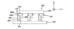
図4Aは、本発明に好ましく用いられるZ駆動機255の一実施形態の斜視図である。この実施形態において、Z駆動機255は、Z出力部400と、Zフレーム402と、Zベアリング404(矢印で示す)と、Z測定器406と、第1駆動用部品256Aと、第2駆動用部品256B(図4Bに示す)とを有する。これらの各構成要素のデザインは、Z駆動機255の設計要求に応じて様々に変更可能である。  FIG. 4A is a perspective view of an embodiment of aZ drive 255 that is preferably used in the present invention. In this embodiment, theZ driving unit 255 includes aZ output unit 400, aZ frame 402, a Z bearing 404 (indicated by an arrow), aZ measuring device 406, afirst driving component 256A, and a second driving unit.Component 256B (shown in FIG. 4B). The design of each of these components can be variously changed according to the design requirements of theZ drive 255.

Z出力部400は、Z軸に沿って、Zフレーム402に対して相対的に移動される。一実施形態において、Z出力部400は、Zレバー408と、Z減衰器410と、Zハウジング412と、1以上のハウジング支持体414と、Z移動体416と、接続部418とを有する。図4Aにおいて、Zレバー408は、剛体であり、Zフレーム402の一部を貫通して延びている。また、Zレバー408は、第2駆動用部品256Bの一部を支持する。  TheZ output unit 400 is moved relative to theZ frame 402 along the Z axis. In one embodiment, theZ output 400 includes aZ lever 408, aZ attenuator 410, aZ housing 412, one or more housing supports 414, aZ moving body 416, and aconnection 418. In FIG. 4A, theZ lever 408 is a rigid body and extends through a part of theZ frame 402. TheZ lever 408 supports a part of thesecond drive component 256B.

Z減衰器410は、Zレバー408の底に固定され、Zレバー408の底をZフレーム402に対して安定させる。一実施形態において、Z減衰器410は、Zレバー408の重量を支持し、Zレバー408がZフレーム402に対して移動するのを許容し、第1ステージ(図4Aでは不図示)からの振動(Z軸に沿ったものを含む)がZレバー408及び第2ステージ(図4Aでは不図示)に伝わるのを抑制する。その結果、Z駆動機255の振動伝播性が比較的低い。換言すると、Z減衰器410は、第1ステージから第2ステージに伝わるはずの振動レベルの抑制が可能である。また、非排他的実施形態である選択肢として、Z減衰器410は、第2ステージに伝わるはずの振動レベルを、少なくとも約1、5、10、20、30、40、50、60、70、80、90、99、あるいは100%近く抑制する。  TheZ attenuator 410 is fixed to the bottom of theZ lever 408 and stabilizes the bottom of theZ lever 408 with respect to theZ frame 402. In one embodiment, theZ attenuator 410 supports the weight of theZ lever 408, allows theZ lever 408 to move relative to theZ frame 402, and vibrates from the first stage (not shown in FIG. 4A). (Including that along the Z axis) is prevented from being transmitted to theZ lever 408 and the second stage (not shown in FIG. 4A). As a result, the vibration propagation property of theZ driving device 255 is relatively low. In other words, theZ attenuator 410 can suppress the vibration level that should be transmitted from the first stage to the second stage. Also, as an option, which is a non-exclusive embodiment, theZ attenuator 410 has a vibration level that should be transmitted to the second stage at least about 1, 5, 10, 20, 30, 40, 50, 60, 70, 80. , 90, 99, or nearly 100%.

Zハウジング412は、第2駆動用部品256Bの一部を支持する。図4Aにおいて、Zハウジング412は、平らな頂部420と、筒状の円筒部422とを有する。一実施形態において、Zハウジング412は、駆動用部品256A,256Bを囲む。  TheZ housing 412 supports a part of thesecond driving component 256B. 4A, theZ housing 412 has a flattop portion 420 and a cylindricalcylindrical portion 422. In one embodiment, theZ housing 412 encloses thedrive components 256A, 256B.

1以上のハウジング支持体414が、Zハウジング412をZレバー408に接続するとともに、第1駆動用部品256Aの一部がZハウジング412の下方に伸びて、Zフレーム402の上端に固定されることを可能にしている。  One ormore housing supports 414 connect theZ housing 412 to theZ lever 408 and a portion of thefirst drive component 256A extends below theZ housing 412 and is secured to the upper end of theZ frame 402. Is possible.

Z移動体416は、概ね平らな円盤状であり、また、概ね平らで且つテーブル(図4Aでは不図示)に面する支持面424を有する。  The Z-movingbody 416 is generally flat and has asupport surface 424 that is generally flat and faces a table (not shown in FIG. 4A).

接続部418は、Z移動体416の底をZハウジング412の上端に、機械的かつフレキシブルに接続する。その結果、Z軸に沿ったZハウジング412の動きが、Z移動体416の動きとなる。接続部418のデザインは、ここで示される内容に従って様々に変更可能である。一実施形態において、接続部418は、Z移動体416とZハウジング412との間で伸びた屈曲部を有する。ここで、「屈曲部」は、いくつかの方向に対して比較的高い剛性を有し、他の方向に対して比較的低い剛性を有する部分を意味する。図4Aにおいて、屈曲部は、(i)X、Y及びZ軸、及びZ軸周りに比較的高い剛性を有し、また、(ii)X及びY軸周りに関して比較的柔軟である。比較的高い剛性と比較的低い剛性との比は、少なくとも約100/1であり、少なくとも約1000/1でもよい。  The connectingportion 418 mechanically and flexibly connects the bottom of theZ moving body 416 to the upper end of theZ housing 412. As a result, the movement of theZ housing 412 along the Z axis becomes the movement of theZ moving body 416. The design of theconnection part 418 can be variously changed according to the content shown here. In one embodiment, the connectingportion 418 has a bent portion extending between theZ moving body 416 and theZ housing 412. Here, the “bending portion” means a portion having a relatively high rigidity in some directions and a relatively low rigidity in other directions. In FIG. 4A, the bent portion has (i) relatively high rigidity around the X, Y, and Z axes, and the Z axis, and (ii) is relatively flexible with respect to the X and Y axes. The ratio of relatively high stiffness to relatively low stiffness is at least about 100/1 and may be at least about 1000/1.

この構成により、Z軸に沿ったZハウジング412の動きがZ軸に沿ったZ移動体416の動きとなる。一方で、接続部418は、Zハウジング412に対して相対的に、Z移動体416が傾いたり、X軸周り及びY軸周りに旋回したりすることを可能にする。なお、接続部418について、他の構成を採用することも可能である。  With this configuration, the movement of theZ housing 412 along the Z axis becomes the movement of theZ moving body 416 along the Z axis. On the other hand, theconnection portion 418 allows theZ moving body 416 to tilt or rotate around the X axis and the Y axis relative to theZ housing 412. Note that other configurations can be employed for the connectingportion 418.

Zフレーム402は、Z出力部400を支持して、第1駆動用部品256Aを支持する。Zフレーム402の大きさ、形状、及びデザインは、様々に変更可能である。図4Aにおいて、Zフレーム402は、概ねE字状であり、上方バーセクション426Aと、下方バーセクション426Bと、上方バーセクション426Aと下方バーセクション426Bとの間に配置される中間バーセクション426Cと、上方、中間、及び下方バーセクション426A,426B,426Cを互いに接続する後方バーセクション426Dと、を有する。図4Aにおいて、上方バーセクション426A及び中間バーセクション426Cは、Zレバー408を受け入れるための開口426Eを有し、下方バーセクション426Bは、Zレバー408の一部を受け入れるためのスロット426Fを有する。さらに、上方バーセクション426A及び中間バーセクション426Cはそれぞれ、Zフレーム402内へのZレバー408の配置のための、選択的に着脱自在な着脱部428を有する。  TheZ frame 402 supports theZ output unit 400 and supports thefirst driving component 256A. The size, shape, and design of theZ frame 402 can be variously changed. In FIG. 4A, theZ frame 402 is generally E-shaped and includes anupper bar section 426A, alower bar section 426B, and anintermediate bar section 426C disposed between theupper bar section 426A and thelower bar section 426B, Arear bar section 426D connecting the upper, middle andlower bar sections 426A, 426B, 426C to each other. In FIG. 4A,upper bar section 426A andmiddle bar section 426C have anopening 426E for receivingZ lever 408, andlower bar section 426B has aslot 426F for receiving a portion ofZ lever 408. In addition, theupper bar section 426A and themiddle bar section 426C each have a selectively removable 428 for placement of theZ lever 408 in theZ frame 402.

下方バーセクション426Bは、第1ステージ238の上端に固定される。また、第1駆動用部品256Aは、上方バーセクション426Aに固定される。  Thelower bar section 426B is fixed to the upper end of thefirst stage 238. Thefirst driving component 256A is fixed to theupper bar section 426A.

Zベアリング404は、Zフレーム402に対するZレバー408の相対的な動きを案内する。一実施形態において、Zベアリング404は、Z軸に沿ったZレバー408の動き(純粋な垂直動作)を許容するとともに、X及びY軸に沿った、またX及びY軸周りに関する、Zフレーム402及び第1ステージに対する相対的なZレバー408の動きを抑制する。一実施形態において、Zベアリング404は、流体タイプのベアリング、あるいは磁気型のベアリングのような、非接触型のベアリングであり、中間バーセクション426CとZレバー408との間に配置される。非接触型のベアリングによって、Zレバー408は、Z軸に沿って、抵抗が全く無いかそれに近い状態で移動することができる。  TheZ bearing 404 guides the relative movement of theZ lever 408 with respect to theZ frame 402. In one embodiment, theZ bearing 404 allows the movement of theZ lever 408 along the Z axis (pure vertical movement), and theZ frame 402 along the X and Y axes and about the X and Y axes. And the movement of theZ lever 408 relative to the first stage is suppressed. In one embodiment, theZ bearing 404 is a non-contact type bearing, such as a fluid type bearing or a magnetic type bearing, and is disposed between theintermediate bar section 426C and theZ lever 408. The non-contact bearing allows theZ lever 408 to move along the Z axis with little or no resistance.

Z測定器406は、Zフレーム402に対するZレバー408の相対的な動きを測定する。Z測定器406は、Z方向に関して、Zフレーム402(第1ステージ238)に対するZレバー408の相対位置を検出する。一実施形態において、この情報は、エアベローズのような、Z減衰器410のZ軸に沿った動き(伸縮)に実質的に相当する。図4Aに示す実施形態において、Z測定器406は、リニアエンコーダである。Zレバー408の動きに関する情報は、制御システム24がZ駆動機255を制御できるように、制御システム24(図1に示す)に送られてもよい。また、例えば、Z測定器406は、静電容量型のゲージ、あるいは他のタイプのセンサーでもよい。  TheZ measuring device 406 measures the relative movement of theZ lever 408 with respect to theZ frame 402. TheZ measuring device 406 detects the relative position of theZ lever 408 with respect to the Z frame 402 (first stage 238) in the Z direction. In one embodiment, this information substantially corresponds to the movement (stretching) of theZ attenuator 410 along the Z axis, such as an air bellows. In the embodiment shown in FIG. 4A, theZ meter 406 is a linear encoder. Information regarding the movement of theZ lever 408 may be sent to the control system 24 (shown in FIG. 1) so that thecontrol system 24 can control theZ drive 255. Further, for example, theZ measuring device 406 may be a capacitance type gauge or another type of sensor.

また、後で詳しく説明する実施形態に示すように、Z測定器406からの情報は、第1ステージから第2ステージに伝わる振動レベルを低減するのに用いることができる。さらに、特定の実施形態において、Z測定器406からの情報は、計測システムの初期化に用いることともできる。  Further, as shown in an embodiment described in detail later, information from theZ measuring device 406 can be used to reduce the vibration level transmitted from the first stage to the second stage. Further, in certain embodiments, information from theZ measurer 406 can also be used to initialize the measurement system.

図4Bは、Z出力部400及び第2駆動用部品256Bの断面斜視図であり、図4Cは、断面平面図である。この実施形態において、Zレバー408は、概ね筒形状である。  4B is a cross-sectional perspective view of theZ output unit 400 and thesecond drive component 256B, and FIG. 4C is a cross-sectional plan view. In this embodiment, theZ lever 408 is generally cylindrical.

図4B及び4Cにおいて、Z減衰器410は、流体ベローズであり、(i)Zレバー408の底に固定された頂部と、(ii)Zフレーム402(図4Aに示す)に取り付けられる底部とを有する。この構成により、Z減衰器410は、Z軸周りのZ出力部400の回転を抑制する。流体ベローズ内の流体の圧力は、Z減衰器410に対する要求に適するように調整される。一実施形態において、流体圧力は、流体ベローズ内にセットされた状態のまま変更されない。あるいは、例えば、流体圧力が流体源(不図示)とともに調整及び制御されてもよい。さらに別の実施形態において、Z減衰器410は、スプリングあるいは別の減衰デバイスであってもよい。  4B and 4C, theZ attenuator 410 is a fluid bellows and comprises (i) a top fixed to the bottom of theZ lever 408 and (ii) a bottom attached to the Z frame 402 (shown in FIG. 4A). Have. With this configuration, theZ attenuator 410 suppresses the rotation of theZ output unit 400 around the Z axis. The pressure of the fluid in the fluid bellows is adjusted to suit the requirements for theZ attenuator 410. In one embodiment, the fluid pressure remains unchanged while set in the fluid bellows. Alternatively, for example, the fluid pressure may be adjusted and controlled with a fluid source (not shown). In yet another embodiment, theZ attenuator 410 may be a spring or another damping device.

また、図4B及び4Cは、第2駆動用部品256Bの詳細も示している。この実施形態において、第2駆動用部品256Bは、Zハウジング412の内側に固定された筒状の外側マグネット430Aと、それに離間しかつ同軸な筒状の内側マグネット430Bとを有する。内側マグネット430Bの底は、Zレバー408の上端に固定され、内側マグネット430Bの上端は、Zハウジング412の頂部420の底に固定されている。  4B and 4C also show details of thesecond drive component 256B. In this embodiment, thesecond driving component 256B includes a cylindricalouter magnet 430A fixed inside theZ housing 412 and a cylindricalinner magnet 430B spaced apart from and coaxial with the cylindricalouter magnet 430A. The bottom of theinner magnet 430B is fixed to the upper end of theZ lever 408, and the upper end of theinner magnet 430B is fixed to the bottom of the top 420 of theZ housing 412.

また、図4B及び4Cは、Zレバー408の上端とZハウジング412の底との間で伸びたハウジング支持体414を示している。  4B and 4C show ahousing support 414 extending between the upper end of theZ lever 408 and the bottom of theZ housing 412. FIG.

図4Dは、Z出力部400、第1駆動用部品256A、及び第2駆動用部品256Bの部分的な拡大断面図である。この実施形態において、第1駆動用部品256Aは、マグネット430A,430Bと同軸配置される筒状のコイル432Aと、離間した複数の脚部432Bとを有し、複数の脚部432Bは、離間した複数のハウジング支持体414の間において、コイル432Aから下方に伸びている。脚部432Bは、コイル432AをZフレーム(図4Dでは不図示)に固定するために用いられる。この構成により、コイル432Aを電流が流れると、マグネット430A,430B及びZ出力部400がZ軸に沿って移動する。矢印433は、マグネットの磁化方向を示す。  FIG. 4D is a partially enlarged cross-sectional view of theZ output unit 400, thefirst driving component 256A, and thesecond driving component 256B. In this embodiment, thefirst driving component 256A has acylindrical coil 432A that is coaxially arranged with themagnets 430A and 430B, and a plurality of spaced leg portions 432B, and the plurality of leg portions 432B are spaced apart from each other. Between the plurality of housing supports 414, thecoil 432A extends downward. The leg 432B is used to fix thecoil 432A to the Z frame (not shown in FIG. 4D). With this configuration, when a current flows through thecoil 432A, themagnets 430A and 430B and theZ output unit 400 move along the Z axis. Anarrow 433 indicates the magnetization direction of the magnet.

また、図4Dは、屈曲部418の詳細を示す。より具体的には、この実施形態において、屈曲部418は、(i)Z移動体416の底に固定される上方円盤状領域434Aと、(ii)Zハウジング412の上端に固定される下方円盤状領域434Bと、(iii)領域434A,434Bを互いに接続する、フレキシブルな接続片434Cとを有する。  FIG. 4D shows details of thebent portion 418. More specifically, in this embodiment, thebent portion 418 includes (i) an upper disk-shapedregion 434A fixed to the bottom of theZ moving body 416, and (ii) a lower disk fixed to the upper end of theZ housing 412. And (iii)flexible connection pieces 434C that connect theregions 434A and 434B to each other.

図5は、第2ステージ240の傾きに伴う、第2ステージ240、3つのZ駆動機255の一部、及びステージベアリング装置257(矢印で示す)の関係を示す模式図である。具体的には、図5に示すように、(i)各テーブルパッド376Aが1つのZ駆動機255の移動体416に位置決めされ、(ii)ステージベアリング装置257によって移動体416からテーブルパッド376Aが離間した状態が維持され、(iii)残りのZ駆動機255に対する各移動体416の傾きを接続部418が許容している。その結果、第2ステージ240が傾いている間、テーブルパッド376Aの支持面374Bが移動体416の支持面424とほぼ平行になるように、移動体416が傾く。ここで、Z軸に沿ったZ駆動機255からの純粋なZ運動は、第2ステージ240を傾けるのに用いることができる。  FIG. 5 is a schematic diagram showing a relationship between thesecond stage 240, a part of the threeZ driving devices 255, and the stage bearing device 257 (indicated by an arrow) according to the inclination of thesecond stage 240. Specifically, as shown in FIG. 5, (i) eachtable pad 376A is positioned on the movingbody 416 of oneZ driving device 255, and (ii) thetable pad 376A is moved from the movingbody 416 by thestage bearing device 257. The separated state is maintained, and (iii) the connectingportion 418 allows the inclination of each movingbody 416 with respect to the remainingZ drive device 255. As a result, while thesecond stage 240 is tilted, the movingbody 416 is tilted so that thesupport surface 374B of thetable pad 376A is substantially parallel to thesupport surface 424 of the movingbody 416. Here, pure Z motion from the Z drive 255 along the Z axis can be used to tilt thesecond stage 240.

図6Aは、別の実施形態である第2移動装置644を有する第2ステージ640の上からの斜視図であり、図6Bは、下からの斜視図である。第2移動装置644は、第1X駆動機652Fと、第2X駆動機652Sと、第1Y駆動機654Fと、第2Y駆動機654Sとを有する。この実施形態において、第2ステージ640は、上記の第2ステージ240と同様である。一方で、この実施形態において、第2移動装置644のX及びY駆動機652F,652S,654F,654Sが異なる。  FIG. 6A is a perspective view from above of thesecond stage 640 having the second movingdevice 644 according to another embodiment, and FIG. 6B is a perspective view from below. The second movingdevice 644 includes a firstX drive unit 652F, a secondX drive unit 652S, a firstY drive unit 654F, and a secondY drive unit 654S. In this embodiment, thesecond stage 640 is the same as thesecond stage 240 described above. On the other hand, in this embodiment, the X andY drivers 652F, 652S, 654F, 654S of the second movingdevice 644 are different.

この実施形態において、X及びY駆動機652F,652S,654F,654Sのそれぞれは、EIコアアクチュエータのような、吸引タイプのアクチュエータである。EIコアアクチュエータの一例が米国特許第6,069,471号明細書に記載されており、そのすべてを援用して本文の記載の一部とする。この実施形態において、第1駆動用部品656Aは、第1ステージ(図6A及び6Bでは不図示)に固定された一対のEコア及び筒状導体を有し、第2駆動用部品656Bは、第2ステージ640に固定されたIコアである。  In this embodiment, each of the X andY drivers 652F, 652S, 654F, 654S is a suction type actuator, such as an EI core actuator. An example of an EI core actuator is described in US Pat. No. 6,069,471, all of which is incorporated herein by reference. In this embodiment, thefirst drive component 656A has a pair of E cores and a cylindrical conductor fixed to a first stage (not shown in FIGS. 6A and 6B), and thesecond drive component 656B It is an I core fixed to the twostage 640.

ここで、X及びY駆動機652F,652S,654F,654Sは、上記のX及びY駆動機252F,252S,254F,254Sが第2ステージ240に固定された方法と同様の方法で第2ステージ640に固定されている。これによって、ステージ装置において、異なるタイプの駆動機に容易に再構成するのが可能になる。  Here, the X andY drivers 652F, 652S, 654F, and 654S are thesecond stage 640 in a manner similar to the method in which the X andY drivers 252F, 252S, 254F, and 254S are fixed to thesecond stage 240. It is fixed to. This allows the stage device to be easily reconfigured to a different type of drive.

図7Aは、別の実施形態である第2移動装置744を有する第2ステージ740を上から見た斜視図であり、図7Bは、横から見た斜視図である。この実施形態において、第2ステージ740は、上記の第2ステージ240と同様である。一方で、この実施形態において、第2移動装置744は、X駆動機752Fの第1ペア(1つのみ図示)と、X駆動機753Fの第2ペア(1つのみ図示)と、第1Y駆動機754Fと、Y駆動機755F,755Sの第2ペアとを有する。  FIG. 7A is a perspective view of asecond stage 740 having a second movingdevice 744 according to another embodiment as seen from above, and FIG. 7B is a perspective view as seen from the side. In this embodiment, thesecond stage 740 is the same as thesecond stage 240 described above. On the other hand, in this embodiment, the second movingdevice 744 includes a first pair (only one shown) of theX driver 752F, a second pair (only one shown) of theX driver 753F, and the first Y drive.Machine 754F and a second pair ofY drive machines 755F and 755S.

この実施形態において、(i)第1ペアの各X駆動機752Fは、EIコアアクチュエータであり、(ii)第2ペアの各X駆動機753Fは、ボイスコイルモータであり、
(iii)Y駆動機754Fは、EIコアアクチュエータであり、(iv)第2ペアの各Y駆動機755F,755Sは、ボイスコイルモータである。この構成により、例えば、(i)X駆動機752Fの第1ペアをX軸に沿った第2ステージ740の素早い粗動に用いることができ、(ii)X駆動機753Fの第2ペアをX軸に沿った第2ステージ740の精密移動に用いることができ、(iii)Y駆動機754FをY軸に沿った第2ステージ740の素早い粗動に用いることができ、(iv)Y駆動機755F,755Sの第2ペアを、Y軸に沿った、また、Z軸周りに関する第2ステージ740の精密な移動に用いることができる。
In this embodiment, (i) each first pair of X drives 752F is an EI core actuator, and (ii) each second pair of X drives 753F is a voice coil motor,
(Iii) TheY drive unit 754F is an EI core actuator, and (iv) each of the second pair ofY drive units 755F and 755S is a voice coil motor. With this configuration, for example, (i) the first pair ofX driver 752F can be used for quick coarse movement of thesecond stage 740 along the X axis, and (ii) the second pair ofX driver 753F is used as X (Iii)Y drive 754F can be used for quick coarse movement of thesecond stage 740 along the Y axis, and (iv) Y drive The second pair of 755F, 755S can be used for precise movement of thesecond stage 740 along the Y axis and about the Z axis.

ここで、X及びY駆動機752F,753F,754F,755F,755Sは、上記のX及びY駆動機252F,252S,254F,254Sが第2ステージ240に固定された方法と同様の方法で第2ステージ740に固定されている。これによって、ステージ装置において、異なるタイプの駆動機に容易に再構成するのが可能になる。  Here, the X andY drivers 752F, 753F, 754F, 755F, and 755S are secondly connected in a manner similar to the method in which the X andY drivers 252F, 252S, 254F, and 254S are fixed to thesecond stage 240. It is fixed to thestage 740. This allows the stage device to be easily reconfigured to a different type of drive.

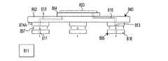
図8は、模式図であり、(i)ワークピース800、(ii)テーブル862、チャック864、及び3つのテーブルパッド874Aを有する第2ステージ840、(iii)3つのZ駆動機855のZ移動体816、及び(iv)ステージベアリング装置857を示す。より具体的には、図8は、低圧あるいは真空などの大気圧とは異なる圧力の流体が流体源811からチャック864に送られる状態の一実施形態を示す。  FIG. 8 is a schematic diagram: (i) aworkpiece 800, (ii) asecond stage 840 having a table 862, achuck 864, and threetable pads 874A, and (iii) Z movement of threeZ drivers 855. Abody 816 and (iv) a stage bearing device 857 are shown. More specifically, FIG. 8 illustrates one embodiment where a fluid at a pressure different from atmospheric pressure, such as low pressure or vacuum, is sent from thefluid source 811 to thechuck 864.

この実施形態において、ステージベアリング装置857は、真空予圧型の流体ベアリングである。また、2つのテーブルパッド874Aは、ステージ通路815,818(想像線で示す)を介してチャック864と流体的につながる入口ポート813を有する。一実施形態において、各移動体816は、流体源811と流体的につながり且つステージベアリング装置857に真空を供給する出口ポート817を有する。  In this embodiment, the stage bearing device 857 is a vacuum preload type fluid bearing. Also, the twotable pads 874A have aninlet port 813 that is in fluid communication with thechuck 864 viastage passages 815, 818 (shown in phantom). In one embodiment, each mobile 816 has anoutlet port 817 that is in fluid communication with afluid source 811 and supplies a vacuum to the stage bearing device 857.

この構成により、第2ステージ840の一部である入口ポート813は、第2ステージ840とともに移動し、出口ポート817は第1ステージとともに移動する。その結果、入口ポート813は、出口ポート817に対して相対的に6自由度に移動することができる。さらに、この構成により、流体源811によって作られた、真空予圧型の流体ベアリング857を構成するための真空の一部を、テーブル862に流用することが可能である。ステージ通路815を経由して供給された真空はチャック864に送られ、ワークピース800をチャック864に保持するためにチャック864に使用される真空が形成される。また、ステージ通路818を経由して供給された真空は、テーブル862を通過してチャック864に送られ、チャック864を第2ステージ840に保持するための真空が形成される。また、この構成により、流体(真空)源811からチャック864まで伸びるホースを設けることなく、真空源811をチャックに接続することが可能である。ここで、入口ポート813と出口ポート817との間には、その間に伸びるホースあるいはチューブのような流体用の導管はない。  With this configuration, theinlet port 813 that is a part of thesecond stage 840 moves together with thesecond stage 840, and theoutlet port 817 moves together with the first stage. As a result, theinlet port 813 can move relative to theoutlet port 817 with six degrees of freedom. Further, with this configuration, it is possible to divert part of the vacuum created by thefluid source 811 to constitute the vacuum preload type fluid bearing 857 to the table 862. The vacuum supplied via thestage passage 815 is sent to thechuck 864, and a vacuum used for thechuck 864 to hold theworkpiece 800 on thechuck 864 is formed. Further, the vacuum supplied via thestage passage 818 passes through the table 862 and is sent to thechuck 864 to form a vacuum for holding thechuck 864 on thesecond stage 840. Further, with this configuration, thevacuum source 811 can be connected to the chuck without providing a hose extending from the fluid (vacuum)source 811 to thechuck 864. Here, there is no fluid conduit such as a hose or tube extending between theinlet port 813 and theoutlet port 817.

図9Aは、図2Aから4Dに示された、ステージ装置220の一部の模式図であり、ステージ装置220は、第1ステージ238と、第2ステージ240と、Z駆動機255とを有する。図9Aには、Z出力部400、Zフレーム402、Z測定器406、第1駆動用部品256A、及びZ駆動機255の第2駆動用部品256Bが示されている。また、図9Aには、Zレバー408、Z減衰器410、各Z出力部400のZ移動体416が示されている。  FIG. 9A is a schematic view of a part of thestage apparatus 220 shown in FIGS. 2A to 4D. Thestage apparatus 220 includes afirst stage 238, asecond stage 240, and aZ drive unit 255. FIG. 9A shows theZ output unit 400, theZ frame 402, theZ measuring device 406, thefirst driving component 256A, and thesecond driving component 256B of theZ driving unit 255. 9A shows theZ lever 408, theZ attenuator 410, and theZ moving body 416 of eachZ output unit 400.

上述したように、Z減衰器410は、Zレバー408の底に固定されており、Zレバー408の底を第1ステージ238に連結している。一実施形態において、Z減衰器410は、Zレバー408の重量及び第2ステージ240の重量を支持し、第1ステージ238に対して相対的にZレバー408が移動するのを可能にし、また、第1ステージ238からZレバー408及び第2ステージ240に伝わる振動レベルを低減する。ここで、Z減衰器410はそれぞれ、ある程度の剛性を有している。非排他的な実施形態において、例えば、各Z減衰器410におけるZ軸に沿った剛性(K)は、約0.1、0.5、1、2、5、10、15、あるいは20N/mmである。  As described above, theZ attenuator 410 is fixed to the bottom of theZ lever 408 and connects the bottom of theZ lever 408 to thefirst stage 238. In one embodiment, theZ attenuator 410 supports the weight of theZ lever 408 and the weight of thesecond stage 240, allows theZ lever 408 to move relative to thefirst stage 238, and The vibration level transmitted from thefirst stage 238 to theZ lever 408 and thesecond stage 240 is reduced. Here, each of theZ attenuators 410 has a certain degree of rigidity. In non-exclusive embodiments, for example, the stiffness (K) along the Z-axis for eachZ attenuator 410 is about 0.1, 0.5, 1, 2, 5, 10, 15, or 20 N / mm. It is.

減衰器410の剛性によって、地表あるいは周辺から第1ステージ238に伝わる外乱の少なくとも一部が、減衰器410を介して第2ステージ240に伝わる。  Due to the rigidity of theattenuator 410, at least a part of the disturbance transmitted from the ground surface or the periphery to thefirst stage 238 is transmitted to thesecond stage 240 via theattenuator 410.

各Z駆動機255に対して、Z測定器406は、第1ステージ238あるいは他の参照に対して相対的な、Zレバー408及びZ減衰器410の一部(例えば頂部)の動き及び/又は位置を測定する。後述するように、制御システム24によるZ減衰器410の剛性及びダンピングを補償するZ駆動機255の制御が可能となるように、Zレバー408の動きに関する情報が、制御システム24(図1に示す)に送られる。  For each Z-drive 255, the Z-measuringdevice 406 moves theZ lever 408 and a portion of the Z attenuator 410 (eg, the top) relative to thefirst stage 238 or other reference and / or Measure the position. As will be described later, information regarding the movement of theZ lever 408 is provided to the control system 24 (shown in FIG. 1) so that theZ drive 255 can be controlled to compensate for the stiffness and damping of theZ attenuator 410 by thecontrol system 24. ).

特定の実施形態において、第1ステージ238に伝わる外乱(地表あるいは周辺などからの)は、X,Y及びZ軸に沿った、また、X,Y及びZ軸周りに関する、第1ステージ238の動作乱れを引き起こす。図9Aに示す減衰器410によって、(i)X,Yに沿った、また、Z軸周りに関する、第1ステージ238の動作乱れが第2ステージ240に伝わらない、(ii)Z軸に沿った、また、X及びY軸周りに関する、第1ステージ238の動作乱れが、減衰器410の一部及びZレバー408におけるZ軸に沿った小さな変位を生じさせる。Z測定器406は、この変位の測定に用いることができる。また、この情報によって、その変位の速度を算出可能である。後述するように、変位及び速度情報を用いることにより、制御システム24は、Z駆動機255を制御し、減衰器410を通して伝わった乱れを補償することができる。  In certain embodiments, disturbances transmitted to the first stage 238 (such as from the ground surface or the surroundings) act on thefirst stage 238 along the X, Y, and Z axes and about the X, Y, and Z axes. Cause disturbance. Theattenuator 410 shown in FIG. 9A causes (i) the disturbance of the operation of thefirst stage 238 along the X and Y axes and around the Z axis not to be transmitted to thesecond stage 240. (ii) along the Z axis Also, the turbulence of thefirst stage 238 about the X and Y axes causes a small displacement along the Z axis in part of theattenuator 410 and theZ lever 408. TheZ measuring device 406 can be used to measure this displacement. Moreover, the speed of the displacement can be calculated from this information. As described below, by using the displacement and velocity information, thecontrol system 24 can control theZ drive 255 to compensate for disturbances transmitted through theattenuator 410.

一実施形態において、+vの速度上昇での+dの変位上昇を伴うZレバー408の移動を招いた第1ステージ238の動きを、Z測定器406が検出すると、制御システムは、Zレバー408の好ましくない変位上昇分を、解消、修正及び/又は減少させるために、Zレバー408に下向きの力が働くように、第1駆動用部品256Aに対して適切な値の出力を行う。同様に、−vの速度降下での−dの変位降下を伴うZレバー408の移動を招いた第1ステージ238の動きを、Z測定器406が検出すると、制御システムは、Zレバー408の好ましくない変位降下分を、解消、修正及び/又は減少させるために、Zレバー408に上向きの力が働くように、第1駆動用部品256Aに対して適切な値の出力を行う。好ましくない変位が全て解消されると、第2ステージ240は、第1ステージ238の動作乱れから分離される。  In one embodiment, when theZ meter 406 detects a movement of thefirst stage 238 that caused the movement of theZ lever 408 with a + d displacement increase at a speed increase of + v, the control system preferably controls theZ lever 408. In order to eliminate, correct, and / or reduce the amount of increase in displacement, an appropriate value is output to thefirst driving component 256A so that a downward force acts on theZ lever 408. Similarly, when theZ measuring device 406 detects the movement of thefirst stage 238 that caused the movement of theZ lever 408 with a −d displacement drop at a −v speed drop, the control system preferably controls theZ lever 408. In order to eliminate, correct, and / or reduce the amount of displacement drop, an appropriate value is output to thefirst driving component 256A so that an upward force is applied to theZ lever 408. When all undesirable displacements are resolved, thesecond stage 240 is separated from the operational disturbance of thefirst stage 238.

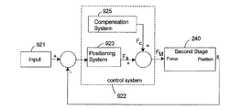
図9Bは、模式的なブロック図であり、Z軸に沿って及び、X及びY軸周りに、第2ステージ240を精密に位置決めするための、第2移動装置244によるZ駆動機255の制御を示す。この実施形態において、第2ステージ240の目標位置は、システムに入力されるインプット921である。目標位置は、測定システム22によって生成された、第2ステージ240のセンサー信号ベクトルSと比較される。インプット921とセンサー信号ベクトルSとの比較によって、相違ベクトルが割り出される。制御システム922(制御システム22)は、第2ステージ240をZ軸に沿って正確に位置決めする指示のための、Z駆動機255に対する出力を割り出す。  FIG. 9B is a schematic block diagram showing the control of theZ driver 255 by the second movingdevice 244 to precisely position thesecond stage 240 along the Z axis and around the X and Y axes. Indicates. In this embodiment, the target position of thesecond stage 240 is aninput 921 that is input to the system. The target position is compared with the sensor signal vector S of thesecond stage 240 generated by themeasurement system 22. By comparing theinput 921 with the sensor signal vector S, the difference vector is determined. The control system 922 (control system 22) determines the output to the Z drive 255 for instructions to accurately position thesecond stage 240 along the Z axis.

一実施形態において、制御システム922は、(i)第2ステージ240の位置決めに必要なZ駆動機255に対する出力値を算出する位置決めシステム923と、(ii)Z減衰器410の剛性及びダンピングの少なくとも一部の補償、及び/又は、Z減衰器410を介して第1ステージ238から第2ステージ240に伝わる振動レベルの少なくとも一部の低減、に必要なZ駆動機255に対する出力値を算出する補償システム925とを有する。制御システム922は、例えば、PID(proportional integral derivative)制御器や、比例ゲインコントローラ、リードラグフィルタ、あるいは制御技術に関する他の一般的に知られたものを有してもよい。  In one embodiment, thecontrol system 922 includes (i) apositioning system 923 that calculates an output value for the Z drive 255 necessary for positioning thesecond stage 240, and (ii) at least the rigidity and damping of theZ attenuator 410. Compensation for calculating an output value for theZ driver 255 necessary for partial compensation and / or reduction of at least part of the vibration level transmitted from thefirst stage 238 to thesecond stage 240 via theZ attenuator 410System 925. Thecontrol system 922 may include, for example, a PID (proportional integral derivative) controller, a proportional gain controller, a lead lag filter, or other commonly known control techniques.

Z駆動機255に対する出力によって、第2ステージ240をターゲットとした総駆動力FMが作られる。一実施形態において、総駆動力は、サーボ力成分FSと、補償力成分FCとを有する。サーボ力成分FSは、第2ステージ240の位置決めのために、第2ステージ240に送られる。補償力成分FCは、Z減衰器410の剛性の少なくとも一部のオフセット及び/又は補償、及び/又はZ減衰器410を介して第1ステージ238から第2ステージ240に伝わる振動レベルの少なくとも一部の低減のために、第2ステージ240に送られる。換言すると、補償力成分FCは、Z減衰器410を通過する第1ステージ238からの乱れの力FD(不図示)を解消するために、負の剛性項及び負のダンピング項を含む。補償力成分FCと乱れの力FDとがほぼ同等の逆関係である場合に、乱れが解消されかつ補償される。なお、非排他的実施形態において、補償力成分FCの絶対値は、乱れの力FDの絶対値の、少なくとも約10、20、40、50、70、80、90、99、100、あるいは110%である。  The total driving force FM targeting thesecond stage 240 is created by the output to theZ driving device 255. In one embodiment, the total driving force has a servo force component FS and a compensation force component FC. The servo force component FS is sent to thesecond stage 240 for positioning thesecond stage 240. The compensation force component FC is an offset and / or compensation of at least a portion of the stiffness of theZ attenuator 410 and / or at least a portion of the vibration level transmitted from thefirst stage 238 to thesecond stage 240 via theZ attenuator 410. Is sent to thesecond stage 240 in order to reduce the above. In other words, the compensation force component FC includes a negative stiffness term and a negative damping term in order to eliminate a disturbance force FD (not shown) from thefirst stage 238 passing through theZ attenuator 410. When the compensation force component FC and the disturbance force FD have substantially the same inverse relationship, the disturbance is eliminated and compensated. In a non-exclusive embodiment, the absolute value of the compensation force component FC is at least about 10, 20, 40, 50, 70, 80, 90, 99, 100, or 110% of the absolute value of the disturbance force FD. It is.

特定の実施形態において、Z駆動機255の性能は相対的に良好であり、Z駆動機255は、補償力成分FCによって打ち消すことが可能な、安定性、再現性、線形剛性を有する。なお、非排他的な実施形態において、補償力成分FCは、Z減衰器410を介して第1ステージ238から第2ステージ240に伝わるはずの乱れ及び/又は振動のレベルを、少なくとも約1、5、10、20、30、40、50、60、70、80、90、99、あるいは100%、低減することができる。  In certain embodiments, the performance of theZ drive 255 is relatively good, and theZ drive 255 has stability, repeatability, and linear stiffness that can be counteracted by the compensation force component FC. Note that in a non-exclusive embodiment, the compensation force component FC has a level of turbulence and / or vibration that is to be transmitted from thefirst stage 238 to thesecond stage 240 via theZ attenuator 410 at least about 1,5. 10, 20, 30, 40, 50, 60, 70, 80, 90, 99, or 100%.

1自由度のシステムにおいて、第1ステージ238に対する相対的な第2ステージ240の動力学は、下式で表すことができる。
Ma+Cv+Kd=F …式(1)
In a one degree of freedom system, the dynamics of thesecond stage 240 relative to thefirst stage 238 can be expressed as:
Ma + Cv + Kd = F Formula (1)

ここで、Mは第2ステージ240の質量であり、CはZ減衰器410のダンピングを表し、KはZ減衰器の剛性を表し、Fは1軸(例えば、Z軸)に沿って第2ステージ240に働く力、aは加速度、vは速度、dは変位である。変位及び速度の情報が有効である場合に、Z減衰器410の剛性(K)及びダンピング(C)の補償にZ駆動機255を使用することができる。Zレバー408の変位及び速度に関する情報は、Z測定器406によって測定することができる。
If F=Cv+Kd+u …式(2)
Here, M is the mass of thesecond stage 240, C is the damping of theZ attenuator 410, K is the stiffness of the Z attenuator, and F is the second along one axis (eg, the Z axis). The force acting on thestage 240, a is acceleration, v is velocity, and d is displacement.Z displacement 255 can be used to compensate for stiffness (K) and damping (C) ofZ attenuator 410 when displacement and velocity information is valid. Information regarding the displacement and speed of theZ lever 408 can be measured by theZ meter 406.
If F = Cv + Kd + u (2)

ここで、uはサーボ力成分FS(目標の力)である。式(1)と式(2)との組み合わせにより、以下の式が成り立つ。
Ma=u …式(3)
Here, u is a servo force component FS (target force). The following expression is established by the combination of Expression (1) and Expression (2).
Ma = u Formula (3)

一実施形態において、変位dをトラジェクトリー・コマンドrとするのが望ましく、このときuはMaとなる。
Ma−Ma=0 …式(4)
そこで、dをrとする。
In one embodiment, it is desirable that the displacement d be a trajectory command r, where u is Ma.
Ma−Ma = 0 Formula (4)
Therefore, d is r.

一般的な6自由度システムにおいて、1自由度システムに用いたのと同じ手法を利用することが可能である。6自由度システム力学は、行列形式で表すことができる。
[M]qa−[C]qv+[K]qd=F …式(5)
In a general six-degree-of-freedom system, it is possible to use the same method as that used for the one-degree-of-freedom system. Six degree of freedom system dynamics can be expressed in matrix form.
[M] qa- [C] qv + [K] qd = F Formula (5)

システムにおける剛性マトリクス[K]及びダンピングマトリクス[C]が算出されると、それらの補償に必要な駆動力を算出することができる。
F=[C]qv+[K]qd+u …式(6)
When the stiffness matrix [K] and the damping matrix [C] in the system are calculated, the driving force necessary to compensate them can be calculated.
F = [C] qv + [K] qd + u Formula (6)

式(5)及び(6)は、式(1)及び(2)と同じ形式である。したがって、より一般化されたベクトル及びマトリクスを用いることによって、6自由度システムにおいて同様の目標を達成することができる。  Equations (5) and (6) are in the same form as equations (1) and (2). Thus, similar goals can be achieved in a six degree of freedom system by using more generalized vectors and matrices.

シミュレートテストの結果は、第1ステージ及び第2ステージを有するステージ装置上で実行されたものである。図9Cから9Eは、グラフ図であり、Z軸に沿った、X軸に沿った、及びY軸に沿った、伝播性のシミュレートテストの結果をそれぞれ示す。伝播性は、異なる周波数にわたる、第1ステージと第2ステージとの間の変位の割合として明示している。シミュレート結果は、剛性及びダンピングの補償によって伝播性が大幅に低減したことを示している。図9Cから9Eは、6自由度シミュレーションによって生成された第1ステージと第2ステージとの間の伝播性のボード線図を示す。振動の100%が第1ステージから第2ステージに伝わるとすると、伝播性の大きさは、1.0、あるいは、0dB(各図9C〜9Eの頂部の線図)である。第2ステージの位置決め正確性の向上のために、第1ステージからの乱れが第2ステージに伝わるのが抑制される。換言すれば、伝播性が、可能な限り小さくなる(図9C〜9Eでは、規模(最大)の負の数値がプロットされている。)。  The result of the simulated test was executed on a stage apparatus having a first stage and a second stage. FIGS. 9C to 9E are graphs showing the results of the simulated propagation test along the Z axis, along the X axis, and along the Y axis, respectively. Propagation is manifested as the rate of displacement between the first stage and the second stage over different frequencies. The simulated results show that the propagation properties are greatly reduced by compensation for stiffness and damping. FIGS. 9C to 9E show Bode diagrams of the propagation between the first stage and the second stage generated by the 6-degree-of-freedom simulation. Assuming that 100% of the vibration is transmitted from the first stage to the second stage, the magnitude of the propagation property is 1.0 or 0 dB (the top diagrams in FIGS. 9C to 9E). In order to improve the positioning accuracy of the second stage, the disturbance from the first stage is prevented from being transmitted to the second stage. In other words, the propagation is as small as possible (in FIGS. 9C-9E, negative values of scale (maximum) are plotted).

図9Cから9Eは、2つのケースの間の伝播性を比較している。ベンチマークケース(破線)は、剛性及びダンピング補償が使用されなかったときの成績である。補償が動作すると(補償ケースは実線で示される)、特に低周波数域において、伝播性の規模が減少する。図9Cから9Eにおいて、X軸は、1、2、5、10、20、50、あるいは100dBの値を有する。  Figures 9C to 9E compare the propagation between the two cases. The benchmark case (dashed line) is the result when stiffness and damping compensation were not used. When compensation operates (compensation case is indicated by a solid line), the scale of propagation decreases, especially in the low frequency range. 9C to 9E, the X axis has a value of 1, 2, 5, 10, 20, 50, or 100 dB.

一実施形態において、各Z駆動機の剛性は、第2ステージをゆっくりと上下に移動させるようにZ駆動機を制御することによって実験的に測定することができる。測定された剛性は、適切な補償力FCを直ちに算出するために、制御システムによって使用される。一実施形態において、例えば、第2ステージは、約0.5秒の間に約2mmの範囲で上下に移動される。  In one embodiment, the stiffness of each Z drive can be measured experimentally by controlling the Z drive to slowly move the second stage up and down. The measured stiffness is used by the control system to immediately calculate an appropriate compensation force FC. In one embodiment, for example, the second stage is moved up and down in a range of about 2 mm in about 0.5 seconds.

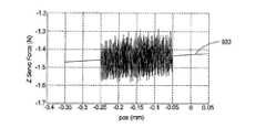
図9Fは、グラフ図であり、Z駆動機による第2ステージの低速移動の間に、Z駆動機によって働く総駆動力のテスト結果を、第2ステージの位置に対して示している。図9Fにおいて、ライン931は、線形剛性を表しており、ここでは3つのZ駆動機における3つの剛性の合計である。この実施形態において、剛性は約9N/mmである。  FIG. 9F is a graph showing the test result of the total driving force exerted by the Z drive during the low speed movement of the second stage by the Z drive with respect to the position of the second stage. In FIG. 9F,line 931 represents linear stiffness, here the sum of the three stiffnesses in the three Z drives. In this embodiment, the stiffness is about 9 N / mm.

図9Gは、Z駆動機を制御する剛性補償の効果を示すグラフ図である。図9Gにおいて、ライン933は、第2ステージの重心に働く総剛性を表している。この実施形態において、第2ステージに働く総剛性は、約50N/mに縮小した。  FIG. 9G is a graph showing the effect of stiffness compensation for controlling the Z drive machine. In FIG. 9G,line 933 represents the total stiffness acting on the center of gravity of the second stage. In this embodiment, the total stiffness acting on the second stage has been reduced to about 50 N / m.

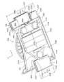
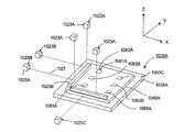
図10Aは、本発明の特徴を備えるステージ装置1020Aを上から見た模式的な斜視図である。例えば、ステージ装置1020Aは、図1の露光装置10における、ウエハステージ装置20として、あるいはレチクルステージ装置18として用いることができる。また、ステージ装置1020Aは、他のタイプのデバイスを移動させるのに用いることができる。  FIG. 10A is a schematic perspective view of astage apparatus 1020A having the features of the present invention as seen from above. For example, thestage apparatus 1020A can be used as thewafer stage apparatus 20 or thereticle stage apparatus 18 in theexposure apparatus 10 of FIG. Thestage apparatus 1020A can also be used to move other types of devices.

図10Aに示されるステージ装置1020Aの構成要素は、第1ステージ1038Aと、第2ステージ1040Aと、測定システム1022Aと、初期化システム1081A(想像線で示す)とを有する。ステージ1038A,1040Aは、対応する上述したデザインと同様のデザインにすることができる。ステージ装置1020Aの第1移動装置及び第2移動装置は、図10Aでは不図示である。移動装置は、図2Aから4Dに示した、上述した構成要素と同様の構成にすることができる。例えば、第1移動装置は、X及びY軸に沿って、及び、Z軸周りに、第1ステージ1038Aを駆動するのに用いられ、第2移動装置は、X、Y、及びZ軸に沿って、及び、X、Y、およびZ軸周りに、第2ステージ1040Aを駆動するのに用いられる。また、例えば、第1移動装置は、3を超える又は3未満の自由度で第1ステージ1038Aを駆動する構成とすることもでき、及び/又は、第2移動装置は、6未満の自由度で第2ステージ1040Aを駆動するのに用いることもできる。  The components ofstage device 1020A shown in FIG. 10A include afirst stage 1038A, asecond stage 1040A, ameasurement system 1022A, and aninitialization system 1081A (shown in phantom).Stages 1038A and 1040A may be similar in design to the corresponding design described above. The first moving device and the second moving device ofstage device 1020A are not shown in FIG. 10A. The mobile device can be configured similarly to the components described above, as shown in FIGS. 2A-4D. For example, the first moving device is used to drive thefirst stage 1038A along the X and Y axes and around the Z axis, and the second moving device is along the X, Y, and Z axes. And about the X, Y, and Z axes, used to drive thesecond stage 1040A. Further, for example, the first moving device can be configured to drive thefirst stage 1038A with a degree of freedom of more than 3 or less than 3, and / or the second moving device has a degree of freedom of less than 6. It can also be used to drive thesecond stage 1040A.

測定システム1022Aは、第2ステージ1040Aの位置を常にモニターする。この情報により、第2移動装置は、第2ステージ1040Aを正確に位置決めするように制御される。測定システム1022Aの構成は、第2ステージ1040Aの自由度に応じて様々に変更可能である。例えば、測定システム1022Aは、少なくとも1軸に沿って及び/又は少なくとも1軸周りに関し、第2ステージ1040Aの位置を測定することができ、また、複数のレーザ干渉計、エンコーダ、及び/又は、他の測定デバイスを利用することもできる。  Themeasurement system 1022A constantly monitors the position of thesecond stage 1040A. Based on this information, the second moving device is controlled to accurately position thesecond stage 1040A. The configuration of themeasurement system 1022A can be variously changed according to the degree of freedom of thesecond stage 1040A. For example, themeasurement system 1022A can measure the position of thesecond stage 1040A along at least one axis and / or about at least one axis, and can also include a plurality of laser interferometers, encoders, and / or others It is also possible to use other measuring devices.

一実施形態において、図10Aに示すように、測定システム1022Aは、3軸及び3軸周りに関して、協調して第2ステージ1040Aの位置をモニターする6つの干渉計システム1023A−1023Cを有する。より具体的には、この実施形態において、測定システム1022Aは、(i)Z軸に沿って及びX軸及びY軸周りに関して、第2ステージ1040Aの位置を協調して測定する、離間した3つのZ干渉計システム1023Aと、(ii)X軸に沿って及びZ軸周りに関して、第2ステージ1040Aの位置を協調して測定する2つのX干渉計システム1023Bと、(iii)Y軸に沿って第2ステージ1040Aの位置を測定するY干渉計システム1023Cと、を有する。この実施形態において、各干渉計システム1023A−1023Cは、第2ステージ1040Aから離れて配置された第1干渉計部品1025Aと、第2ステージ1040Aに固定され第2ステージ1040Aとともに移動する第2干渉計部品1025Bとを有する。干渉計部品1025A,1025Bの正確な位置は、ステージ装置1020Aの所望の性能を達成するために様々に変更可能である。  In one embodiment, as shown in FIG. 10A,measurement system 1022A includes sixinterferometer systems 1023A-1023C that coordinately monitor the position ofsecond stage 1040A about three axes and about three axes. More specifically, in this embodiment, themeasurement system 1022A includes (i) three spaced apart measurements that coordinately measure the position of thesecond stage 1040A along the Z axis and about the X and Y axes.A Z interferometer system 1023A; (ii) twoX interferometer systems 1023B that coordinately measure the position of thesecond stage 1040A along and around the X axis; and (iii) along the Y axisY interferometer system 1023C for measuring the position of thesecond stage 1040A. In this embodiment, eachinterferometer system 1023A-1023C includes afirst interferometer component 1025A disposed away from thesecond stage 1040A, and a second interferometer that is fixed to thesecond stage 1040A and moves with thesecond stage 1040A. And acomponent 1025B. The exact position of theinterferometer components 1025A, 1025B can be varied in various ways to achieve the desired performance of thestage apparatus 1020A.

図10Aに示す実施形態において、(i)各第1干渉計部品1025Aは、第2干渉計部品1025Bにレーザビーム1027を照射しかつその第2干渉計部品で反射したビームを受ける干渉計ブロックであり、(ii)各第2干渉計部品1025Bは、ミラーなどの反射体である。また、第1干渉計部品が反射体を有しかつ第2干渉計部品が干渉計ブロックを有する構成とすることもできる。適切なレーザ干渉計は、カルフォルニア、サンタクララのアジレントで販売されている。  In the embodiment shown in FIG. 10A, (i) eachfirst interferometer component 1025A is an interferometer block that irradiates thesecond interferometer component 1025B with alaser beam 1027 and receives the beam reflected by the second interferometer component. (Ii) Eachsecond interferometer component 1025B is a reflector such as a mirror. Alternatively, the first interferometer component may have a reflector and the second interferometer component may have an interferometer block. A suitable laser interferometer is sold by Agilent in Santa Clara, California.

特定の実施形態において、X、Y、及びZ軸周りに関する、第2ステージ1040Aの機械的動作範囲は、1以上の干渉計システム1023A−1023Cの作動範囲よりも広い。換言すると、1以上の干渉計システム1023A−1023Cは、作動回転範囲に制限がある。例えば、各干渉計システム1023A−1023Cが適切に機能するために、干渉計ブロックからのビーム1027は、反射体(第2干渉計部品)で反射されてその干渉計ブロックに戻る必要がある。反射体の角度が作動回転範囲内にない場合、干渉計ブロックにビームが戻らない可能性がある。一実施形態において、各Z干渉計システム1023Aは、FA作動範囲を有し、各X干渉計システム1023Bは、SA作動範囲を有し、Y干渉計システム1023Cは、TA作動範囲を有する。  In certain embodiments, the mechanical operating range of thesecond stage 1040A about the X, Y, and Z axes is wider than the operating range of the one ormore interferometer systems 1023A-1023C. In other words, the one ormore interferometer systems 1023A-1023C have a limited operating rotation range. For example, in order for eachinterferometer system 1023A-1023C to function properly, thebeam 1027 from the interferometer block needs to be reflected off the reflector (second interferometer component) and back to that interferometer block. If the reflector angle is not within the operating rotation range, the beam may not return to the interferometer block. In one embodiment, eachZ interferometer system 1023A has an FA operating range, eachX interferometer system 1023B has an SA operating range, andY interferometer system 1023C has a TA operating range.

制限された各作動回転範囲の大きさは、干渉計システム1023A−1023Cのタイプに応じて様々に変更可能である。例えば、1つのタイプの干渉計システム1023A−1023Cにおいて、適切に機能するためには、反射体がビーム1027に対して90°±0.06°である必要がある。この構成において、作動範囲は、約0.12°である。また、非排他的な実施形態において、作動範囲は、約0.01、0.05、0.1、あるいは0.5°である。  The size of each limited operational rotation range can be varied depending on the type ofinterferometer system 1023A-1023C. For example, in one type ofinterferometer system 1023A-1023C, the reflector needs to be 90 ° ± 0.06 ° relative to thebeam 1027 in order to function properly. In this configuration, the operating range is about 0.12 °. Also, in non-exclusive embodiments, the operating range is about 0.01, 0.05, 0.1, or 0.5 °.

ステージ装置1020Aに最初に出力が加えられたとき、第2ステージ1040Aは、通常、未知の方位にあり、また、第2ステージ1040Aが作動範囲外に回転していて1以上の干渉計システム1023A−1023Cが稼動しない可能性がある。例えば、FA作動範囲を超えて、第2ステージ1040AがX軸又はY軸周りに回転している場合、Z干渉計システム1023Aが機能しない可能性がある。ほぼ同様に、SA作動範囲及びTA作動範囲を超えて第2ステージ1040AがZ軸周りに回転している場合、X及びY干渉計システム1023B,1023Cが機能しない可能性がある。  When power is first applied to thestage apparatus 1020A, thesecond stage 1040A is typically in an unknown orientation, and thesecond stage 1040A is rotating out of the operating range so that one ormore interferometer systems 1023A-The 1023C may not operate. For example, when thesecond stage 1040A rotates around the X axis or the Y axis beyond the FA operation range, theZ interferometer system 1023A may not function. In a similar manner, the X andY interferometer systems 1023B, 1023C may not function if thesecond stage 1040A rotates about the Z axis beyond the SA operating range and TA operating range.

この構成において、初期化システム1081Aは、干渉計システム1023A−1023Cが未稼動の際に、第2ステージ1040Aが正確な方位に調整されるようにする。一実施形態において、初期化システム1081Aは、第2ステージ1040Aが作動範囲を超えて回転しているときの、第2ステージ1040Aの位置をモニターする。この実施形態において、初期化システム1081Aは、第2ステージ1040Aが作動範囲外にある及び/又は第2ステージ1040Aの機械的最大動作範囲を超えているときの、第2ステージ1040Aの位置を測定可能な1以上のセンサーを有する。  In this configuration, theinitialization system 1081A ensures that thesecond stage 1040A is adjusted to the correct orientation when theinterferometer systems 1023A-1023C are not in operation. In one embodiment, theinitialization system 1081A monitors the position of thesecond stage 1040A when thesecond stage 1040A is rotating beyond the operating range. In this embodiment, theinitialization system 1081A can measure the position of thesecond stage 1040A when thesecond stage 1040A is outside the operating range and / or exceeds the mechanical maximum operating range of thesecond stage 1040A. One or more sensors.

図10Aに示す実施形態において、初期化システム1081Aは、6つの初期センサー1083A−1083C(想像線で示される)を有し、それらはすなわち、(i)Z軸に沿って及びX軸周り及びY軸周りに関して、第1ステージ1038Aに対する第2ステージ1040Aの位置を協調して測定する離間した3つのZセンサー1083Aと、(ii)X軸に沿って及びY軸周りに関して、第1ステージ1038Aに対する第2ステージ1040Aの位置を協調して測定する離間した2つのXセンサー1083Bと、(iii)Y軸に沿って、第1ステージ1038Aに対する第2ステージ1040Aの位置を測定するYセンサー1083Cと、を有する。なお、例えば、初期化システム1081Aは、6未満あるいは6を超えるセンサー、及び/又は、第1ステージ1038A以外の他の構造物に対して移動体を参照可能な1以上のセンサーを有してもよい。  In the embodiment shown in FIG. 10A, theinitialization system 1081A has sixinitial sensors 1083A-1083C (shown in phantom) that are (i) along the Z axis and around the X axis and YThree Z sensors 1083A spaced apart to coordinately measure the position of thesecond stage 1040A relative to thefirst stage 1038A with respect to the axis, and (ii) the first relative to thefirst stage 1038A along the X axis and about the Y axis. Two spaced apartX sensors 1083B that cooperatively measure the position of the twostage 1040A, and (iii) aY sensor 1083C that measures the position of thesecond stage 1040A relative to thefirst stage 1038A along the Y axis. . For example, theinitialization system 1081A may include less than 6 or more than 6 sensors and / or one or more sensors that can refer to the moving body with respect to other structures other than thefirst stage 1038A. Good.

一実施形態において、1以上の初期センサー1083A−1083Cは、固定されたゼロ位置を有するアブソリュート型とすることができる。そうしたタイプのセンサーの1つとして、静電容量ゲージがある。他のアブソリュート型のセンサーとして、ポテンショメータ、LVDTS、及び多くの光学センサーがある。アブソリュート型のセンサー1083A−1083Cにより、X,Y,及び/又はZ軸周りに関する第2ステージ1040Aの所望の方位を、特定の検出値に関連付けることができる。アブソリュート型のセンサー1083A−1083Cに対する正確な目標値は、制御システム24(図1に示す)の初期化ソフトウェアプログラムに保存することができる。アブソリュート型のセンサーの使用により、干渉計システム1023A−1023Cの比較的高速での初期化が可能となる。  In one embodiment, the one or moreinitial sensors 1083A-1083C may be absolute with a fixed zero position. One such type of sensor is a capacitance gauge. Other absolute sensors include potentiometers, LVDTS, and many optical sensors.Absolute type sensors 1083A-1083C allow the desired orientation ofsecond stage 1040A with respect to the X, Y, and / or Z axis to be associated with a particular detection value. Accurate target values for theabsolute sensors 1083A-1083C can be stored in the initialization software program of the control system 24 (shown in FIG. 1). By using an absolute type sensor, theinterferometer systems 1023A-1023C can be initialized at a relatively high speed.

別の実施形態において、1以上の初期センサー1083A−1083Cは、第1ステージ1038Aに対する第2ステージ1040Aのインクリメンタルな動きを測定するインクリメンタル型のセンサーとすることもできる。そうしたタイプのセンサーの1つとして、エンコーダがある。図10Aに示す実施形態では、ステージ装置1020Aが始動すると、初期化プロセスが開始し、制御システムが、初期センサー1083A−1083Cからの位置情報を用いて第2移動装置を制御する。この制御は、初期の比較的低いバンドウィドスにおいて、オプション的に生じる。この構成により、その初期位置から目標位置に向けて第2ステージ1040Aが徐々に移動するように、第2移動装置が制御される。第2ステージ1040Aが正確な方位で一旦安定すると、干渉計システム1023A−1023Cが初期化される。その後、干渉計システム1023A−1023Cからの位置情報を用いて制御システムが第2移動装置を制御する。任意的に、バンドウィドスが変化して高くなる。  In another embodiment, the one or moreinitial sensors 1083A-1083C may be incremental sensors that measure the incremental movement of thesecond stage 1040A relative to thefirst stage 1038A. One such type of sensor is an encoder. In the embodiment shown in FIG. 10A, whenstage device 1020A is started, the initialization process begins and the control system controls the second mobile device using position information frominitial sensors 1083A-1083C. This control occurs optionally at the initial relatively low bandwidth. With this configuration, the second moving device is controlled so that thesecond stage 1040A gradually moves from the initial position toward the target position. Once thesecond stage 1040A is stabilized in the correct orientation, theinterferometer systems 1023A-1023C are initialized. Thereafter, the control system controls the second mobile device using the position information from theinterferometer systems 1023A-1023C. Optionally, the band width changes and increases.

図10Bは、本発明の特徴を有するステージ装置1020Bの別の実施形態の一部の、模式的な上からの斜視図である。例えば、ステージ装置1020Bは、図1の露光装置10における、ウエハステージ装置20として、あるいはレチクルステージ装置18として用いることができる。また、ステージ装置1020Bは、他のタイプのデバイスを移動させるのに用いることができる。  FIG. 10B is a schematic top perspective view of a portion of another embodiment of astage apparatus 1020B having features of the present invention. For example, thestage apparatus 1020B can be used as thewafer stage apparatus 20 or thereticle stage apparatus 18 in theexposure apparatus 10 of FIG. Thestage apparatus 1020B can be used to move other types of devices.

図10Bに示されるステージ装置1020Bの構成要素は、第1ステージ1038Bと、第2ステージ1040Bと、測定システム1022Bと、初期化システム1081Bとを有する。ステージ1038B,1040B、及び測定システム1022Bは、対応する上述したデザインと同様のデザインにすることができる。図10Bにおいて、測定システム1022Bはまた、3軸に沿って及び3軸周りに関して、協調して第2ステージ1040Aの位置をモニターする6つの干渉計システム1023A−1023Cを有する。  The components of thestage apparatus 1020B shown in FIG. 10B include afirst stage 1038B, asecond stage 1040B, ameasurement system 1022B, and aninitialization system 1081B.Stages 1038B, 1040B, andmeasurement system 1022B may be similar in design to the corresponding designs described above. In FIG. 10B,measurement system 1022B also has sixinterferometer systems 1023A-1023C that coordinately monitor the position ofsecond stage 1040A along and around three axes.

図10Bにおいて、初期化システム1081Bはまた、干渉計システム1023A−1023Cが未稼動の際に、第2ステージ1040Aが正確な方位に調整されるようにする。この実施形態において、初期化システム1081Aは、1以上のアライナー1085A−1085Cを有し、それらは、第2ステージ1040Aのさらなる動きを抑制するものであり、第2ステージ1040Bが各稼動範囲内で回転されるように、位置決めされている。  In FIG. 10B, theinitialization system 1081B also ensures that thesecond stage 1040A is adjusted to the correct orientation when theinterferometer systems 1023A-1023C are not in operation. In this embodiment, theinitialization system 1081A has one ormore aligners 1085A-1085C that suppress further movement of thesecond stage 1040A, and thesecond stage 1040B rotates within each operating range. To be positioned.

図10Bに示す実施形態において、初期化システム1081Bは、3つのアライナー1085A−1085C、すなわち、Zアライナー1085A、Xアライナー1085B、及びYアライナー1085Cを有する。この実施形態において、Zアライナー1085Aは、Z軸に沿った第2ステージ1040Bの動きを協調して抑制しかつ、X及びY軸周りに第2ステージ1040Bを方向付ける、離間した3つの硬質なZストップ体1087A(想像線で示される)を有する。Xアライナー1085Bは、X軸に沿って第2ステージ1040Bの動きを協調して抑制しかつ、Z軸周りに第2ステージ1040Bを方向付ける、離間した2つの硬質なXストップ体1087Bを有する。Yアライナー1085Bは、Y軸に沿って第2ステージ1040Bの動きを抑制する硬質なYストップ体1087Cを有する。また、例えば、初期化システム1081Bは、3未満あるいは3を超えるアライナーを有することもできる。例えば、X、Y、及びZ軸周りに関して、他のアライナー1085A,1085Bによって第2ステージ1040Bを適切に方向付けることが可能であるから、Yアライナー1085Cは、必ずしも必要でない。  In the embodiment shown in FIG. 10B, theinitialization system 1081B has threealigners 1085A-1085C: a Z aligner 1085A, anX aligner 1085B, and aY aligner 1085C. In this embodiment, theZ aligner 1085A cooperates to restrain movement of thesecond stage 1040B along the Z axis and directs thesecond stage 1040B about the X and Y axes to be spaced apart from three rigid Zs. It has astop body 1087A (shown in phantom). TheX aligner 1085B has two hardX-stop bodies 1087B spaced apart to coordinately restrain the movement of thesecond stage 1040B along the X axis and to direct thesecond stage 1040B around the Z axis. TheY aligner 1085B has a hard Y stopbody 1087C that suppresses the movement of thesecond stage 1040B along the Y axis. Also, for example, theinitialization system 1081B can have less than three or more than three aligners. For example, theY aligner 1085C is not necessarily required because thesecond stage 1040B can be properly oriented byother aligners 1085A, 1085B around the X, Y, and Z axes.

一実施形態において、1以上の硬質なストップ体1087A−1087Cは、アライメントの進行を妨げる摩擦を抑制するために、低摩擦材料又は回転要素(カムフォロアなど)から構成される接触領域1089を有する。  In one embodiment, the one or morehard stop bodies 1087A-1087C have acontact area 1089 comprised of a low friction material or a rotating element (such as a cam follower) to suppress friction that hinders alignment progress.

また、例えば、1以上の硬質なストップ体を、1以上のリミットスイッチ又は光学センサに置き換えることもできる。  For example, one or more hard stop bodies can be replaced with one or more limit switches or optical sensors.

図10Bにおいて、各ストップ体1087A−1087Cは、第1ステージ1038Bに取り付けられ、接触領域1089が第2ステージ1040Bに係わっている。また、例えば、1以上のストップ体1087A−1087Cは、他の構造体に取り付けられてもよい。例えば、1以上のストップ体1087A−1087Cが第2ステージ1040Bに固定され、接触領域1089が第1ステージ1038Bに係わってもよい。  In FIG. 10B, eachstop body 1087A-1087C is attached to thefirst stage 1038B, and thecontact area 1089 is engaged with thesecond stage 1040B. Also, for example, one ormore stop bodies 1087A-1087C may be attached to other structures. For example, one ormore stop bodies 1087A-1087C may be fixed to thesecond stage 1040B, and thecontact area 1089 may be related to thefirst stage 1038B.

この構成において、ステージ装置1020Bが始動すると、初期化プロセスが開始し、制御システムが、位置情報なしでオープンループ方式で第2移動装置を制御する。この構成により、その初期位置から1軸に沿って(例えば、Z軸に沿って)、第2ステージ1040Aが個別のストップ体1087A−1087C(Zストップ体1087Aなど)に係わるまで、第2ステージ1040Aが徐々に移動するように、第2移動装置が制御される。次に、第2ステージ1040Aが次の軸に沿って(例えば、X軸に沿って)、第2ステージ1040Aが個別のストップ体1087A−1087C(Xストップ体1087Bなど)に係わるまで、第2ステージ1040Aが徐々に移動するように、第2移動装置が制御される。最後に、第2ステージが残りの軸に沿って(例えば、Y軸に沿って)、第2ステージ1040が個別のストップ体1087A−1087C(Yストップ体1087Cなど)に係わるまで、第2ステージ1040Aが徐々に移動するように、第2移動装置が制御される。  In this configuration, when thestage device 1020B is started, an initialization process is started and the control system controls the second moving device in an open loop manner without position information. With this configuration, thesecond stage 1040A is moved from its initial position along one axis (eg, along the Z axis) until thesecond stage 1040A is engaged with theindividual stop bodies 1087A-1087C (such as theZ stop body 1087A). Is moved gradually so that the second moving device is controlled. Thesecond stage 1040A is then moved along the next axis (eg, along the X axis) until thesecond stage 1040A is engaged with anindividual stop body 1087A-1087C (such as theX stop body 1087B). The second moving device is controlled so that 1040A gradually moves. Finally, thesecond stage 1040A until the second stage is along the remaining axis (eg, along the Y axis) and the second stage 1040 is engaged with theindividual stop bodies 1087A-1087C (such as theY stop body 1087C). Is moved gradually so that the second moving device is controlled.

第2ステージ1040Aがストップ体1087−1087Cに寄せられて一旦位置決めされると、干渉計システム1023A−1023Cが初期化される。その後、干渉計システム1023A−1023Cからの位置情報を用いて制御システムが第2移動装置を制御する。ここで、第2ステージ1040BがZストップ体1087Aに係わると、X及びY干渉計システム1023B,1023Cが初期化され、第2ステージ1040BがXストップ体1087Bに係わると、Z干渉計システム1023Aが初期される。  Once thesecond stage 1040A is moved to the stop body 1087-1087C and positioned, theinterferometer systems 1023A-1023C are initialized. Thereafter, the control system controls the second mobile device using the position information from theinterferometer systems 1023A-1023C. Here, when thesecond stage 1040B is related to theZ stop body 1087A, the X andY interferometer systems 1023B and 1023C are initialized, and when thesecond stage 1040B is related to theX stop body 1087B, theZ interferometer system 1023A is initialized. Is done.

特定の構成において、第2移動装置における駆動機の起動は、第2ステージ1040Bの繰り返し可能なアライメントを作り出すシーケンスによって生じる。  In certain configurations, activation of the drive in the second mobile device is caused by a sequence that creates a repeatable alignment of thesecond stage 1040B.

図10Cは、本発明の特徴を有するステージ装置1020Cのさらに別の実施形態一部を、上から見た模式的な斜視図である。例えば、ステージ装置1020Cは、図1の露光装置10における、ウエハステージ装置20として、あるいはレチクルステージ装置18として用いることができる。また、ステージ装置1020Aは、他のタイプのデバイスを移動させるのに用いることができる。  FIG. 10C is a schematic perspective view of a part of still another embodiment of thestage apparatus 1020C having the features of the present invention as viewed from above. For example, thestage apparatus 1020C can be used as thewafer stage apparatus 20 or thereticle stage apparatus 18 in theexposure apparatus 10 of FIG. Thestage apparatus 1020A can also be used to move other types of devices.

図10Cに示すステージ装置1020Cの構成要素は、第1ステージ1038Cと、第2ステージ1040Cと、測定システム1022Cと、初期化システム1081Cとを有する。ステージ1038C,1040C、及び測定システム1022Cは、対応する上述したデザインと同様のデザインにすることができる。図10Cにおいて、測定システム1022Cはまた、3軸に沿って及び3軸周りに関して、協調して第2ステージ1040Cの位置をモニターする6つの干渉計システム1023A−1023Cを有する。  The components of thestage apparatus 1020C shown in FIG. 10C include afirst stage 1038C, asecond stage 1040C, ameasurement system 1022C, and aninitialization system 1081C.Stages 1038C, 1040C, andmeasurement system 1022C may be similar in design to the corresponding designs described above. In FIG. 10C,measurement system 1022C also has sixinterferometer systems 1023A-1023C that coordinately monitor the position ofsecond stage 1040C along and about three axes.

図10Cにおいて、初期化システム1081Cは、1以上の初期センサー1083A−1083C、及び1以上のアライナー1085Aの組み合わせを有する。  In FIG. 10C, theinitialization system 1081C has a combination of one or moreinitial sensors 1083A-1083C and one ormore aligners 1085A.

図10Cに示す実施形態において、初期化システム1081Cは、6つの初期センサー1083A−1083C(想像線で示される)を有し、それらはすなわち、(i)Z軸に沿って及びX軸周り及びY軸周りに関して、第2ステージ1040Aの位置を協調して測定する離間した3つのZセンサー1083Aと、(ii)X軸に沿って及びZ軸周りに関して、第2ステージ1040Aの位置を協調して測定する離間した2つのXセンサー1083Bと、(iii)Y軸に沿って、第1ステージ1038Aに対する第2ステージ1040Aの位置を測定するYセンサー1083Cと、(iv)Z軸に沿った第2ステージ1040Bの動きを協調して抑制しかつ、X及びY軸周りに第2ステージ1040Bを方向付ける、Zストップ体1087Aを有するZアライナー1085A(想像線で示す)と、を有する。  In the embodiment shown in FIG. 10C, theinitialization system 1081C has sixinitial sensors 1083A-1083C (shown in phantom) that are (i) along the Z axis and around the X axis and Y Three spacedZ sensors 1083A that coordinately measure the position of thesecond stage 1040A around the axis, and (ii) coordinately measure the position of thesecond stage 1040A along the X axis and around the Z axis Two separatedX sensors 1083B, (iii) aY sensor 1083C for measuring the position of thesecond stage 1040A relative to thefirst stage 1038A along the Y axis, and (iv) asecond stage 1040B along the Z axis. Z-axis having a Z-stop body 1087A that controls the movement of thesecond stage 1040B around the X and Y axes in a coordinated manner.Liner 1085A (shown in phantom).

この実施形態において、各Zセンサー1083Aは、インクリメンタル型のセンサーであり、X及びYセンサー1083B,1083Cは、アブソリュート型のセンサーである。この実施形態において、1以上のZ測定器406(図4A及び9Aに示す)をZセンサー1083Aとして用いることもできる。  In this embodiment, eachZ sensor 1083A is an incremental sensor, and the X andY sensors 1083B and 1083C are absolute sensors. In this embodiment, one or more Z measurers 406 (shown in FIGS. 4A and 9A) can also be used as theZ sensor 1083A.

この実施形態において、ステージ装置1020Bが始動すると、初期化プロセスが開始し、制御システムが、初期センサー1083A−1083Cからの位置情報を用いて第2移動装置を制御する。この構成により、その初期位置から1軸に沿って(例えば、Z軸に沿って)、第2ステージ1040Aが個別のストップ体1087A−1087C(Zストップ体1087Aなど)に係わるまで、第2ステージ1040Aが徐々に移動するように、第2移動装置が制御される。また、X及びY軸に沿って及びZ軸周りに、その初期位置から目標位置に向けて第2ステージ1040Aが徐々に移動するように、X及びYセンサー1083B,1083Cからの位置情報を用いて、第2移動装置が制御される。第2ステージ1040Aが正確な方位で一旦安定すると、干渉計システム1023A−1023Cが初期化される。その後、制御システムは、干渉計システム1023A−1023Cからの位置情報用いて第2移動装置を制御する。  In this embodiment, whenstage device 1020B is started, an initialization process begins and the control system controls the second mobile device using position information frominitial sensors 1083A-1083C. With this configuration, thesecond stage 1040A is moved from its initial position along one axis (eg, along the Z axis) until thesecond stage 1040A is engaged with theindividual stop bodies 1087A-1087C (such as theZ stop body 1087A). Is moved gradually so that the second moving device is controlled. Further, position information from the X andY sensors 1083B and 1083C is used so that thesecond stage 1040A gradually moves from the initial position toward the target position along the X and Y axes and around the Z axis. The second moving device is controlled. Once thesecond stage 1040A is stabilized in the correct orientation, theinterferometer systems 1023A-1023C are initialized. Thereafter, the control system controls the second mobile device using the position information from theinterferometer systems 1023A-1023C.

上述したように、Z減衰器410の剛性補償のためのZ測定器406(図4A及び9Aに示す)は、アブソリュート型のセンサー又はインクリメンタル型のセンサーとすることができる。1以上のZ測定器406がアブソリュート型のセンサーである場合、Z測定器406は、初期化システム1081A及び1081Cの初期センサーにおけるZセンサー1083Aとして用いることができる。  As described above, the Z measuring device 406 (shown in FIGS. 4A and 9A) for stiffness compensation of theZ attenuator 410 can be an absolute type sensor or an incremental type sensor. If one ormore Z measurers 406 are absolute sensors, theZ measurer 406 can be used as theZ sensor 1083A in the initial sensors of theinitialization systems 1081A and 1081C.

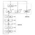
半導体デバイスは、図11Aに概略的に示すプロセスによって、上記のシステムを用いて製造される。ステップ1101において、デバイスの機能及び特性の設計が行われる。次に、ステップ1102において、前記設計ステップに従ったパターンを有するマスク(レチクル)が設計され、平行したステップ1103において、シリコン材料からウエハが製造される。ステップ1104において、本発明に係る上記のフォトリソグラフィシステムによって、ステップ1102で設計されたマスクパターンが、ステップ1103からのウエハ上に露光される。ステップ1105において、半導体デバイスが組み立てられ(ダイシング工程、ボンティング工程、及びパッケージング工程を含む)、最後に、ステップ1106においてデバイスが検査される。  A semiconductor device is manufactured using the system described above by the process schematically shown in FIG. 11A. Instep 1101, the function and characteristics of the device are designed. Next, instep 1102, a mask (reticle) having a pattern according to the design step is designed, and in aparallel step 1103, a wafer is manufactured from a silicon material. Instep 1104, the mask pattern designed instep 1102 is exposed on the wafer fromstep 1103 by the above-described photolithography system according to the present invention. Instep 1105, the semiconductor device is assembled (including a dicing process, a bonding process, and a packaging process), and finally, instep 1106, the device is inspected.

図11Bは、半導体デバイスの製造の場合における上記のステップ1104の詳細なフローの一例を示す。図11Bにおいて、ステップ1111(酸化ステップ)において、ウエハ表面が酸化する。ステップ111(CVDステップ)において、ウエハ表面に絶縁膜が形成される。ステップ1113(電極形成ステップ)において、蒸着によってウエハ上に電極が形成される。ステップ1114(イオン打込みステップ)において、ウエハにイオンが打ち込まれる。以上のステップ1111−1114は、ウエハ処理の各段階の前処理工程を構成しており、各段階において必要な処理に応じて選択される。  FIG. 11B shows an example of a detailed flow of theabove step 1104 in the case of manufacturing a semiconductor device. In FIG. 11B, in step 1111 (oxidation step), the wafer surface is oxidized. In step 111 (CVD step), an insulating film is formed on the wafer surface. In step 1113 (electrode formation step), an electrode is formed on the wafer by vapor deposition. In step 1114 (ion implantation step), ions are implanted into the wafer. The above steps 1111 to 1114 constitute a pre-processing process at each stage of wafer processing, and are selected according to necessary processes at each stage.

ウエハプロセスの各段階において、上述の前処理工程が終了すると、以下のようにして後処理工程が実行される。後処理工程では、まず、ステップ1115(レジスト形成ステップ)において、ウエハに感光剤が塗布される。次に、ステップ1116(露光ステップ)において、上記の露光装置を用いて、マスク(レチクル)の回路パターンがウエハに転写される。続くステップ1117(現像ステップ)において、露光されたウエハが現像され、ステップ1118(エッチングステップ)において、レジストが残存している部分以外の部分(露光された材料表面)がエッチングにより取り除かれる。ステップ1119(フォトレジスト除去ステップ)において、エッチング後の不要な残りのレジストが取り除かれる。こうした前処理工程と後処理工程との繰り返しによって、多数の回路パターンが形成される。  At each stage of the wafer process, when the above pre-process is completed, the post-process is executed as follows. In the post-processing step, first, in step 1115 (resist formation step), a photosensitive agent is applied to the wafer. Next, in step 1116 (exposure step), the circuit pattern of the mask (reticle) is transferred to the wafer using the above exposure apparatus. In the following step 1117 (developing step), the exposed wafer is developed, and in step 1118 (etching step), portions other than the portions where the resist remains (exposed material surface) are removed by etching. In step 1119 (photoresist removal step), unnecessary residual resist after etching is removed. A large number of circuit patterns are formed by repeating the pre-processing step and the post-processing step.

本発明は、液体に適した測定器を用いることによって、液浸タイプの露光装置に適用可能である。例えば、国際公開第99/49504号は、露光プロセスにおいて基板(ウエハ)と投影レンズ系との隙間に液体を供給する露光装置を開示している。許容される範囲内で、国際公開第99/49504号の開示を援用して本文の記載の一部とする。  The present invention can be applied to an immersion type exposure apparatus by using a measuring device suitable for a liquid. For example, WO99 / 49504 discloses an exposure apparatus that supplies liquid to a gap between a substrate (wafer) and a projection lens system in an exposure process. To the extent permitted, the disclosure of WO 99/49504 is incorporated herein by reference.

また、本発明は、2以上の基板及び/又はレチクルステージを有する露光装置にも適用可能である。こうした装置では、露光のために他のステージが用いられている間に、平行して又は予備ステップに追加のステージが用いられる。こうしたマルチステージ露光装置は、例えば、特開平10−163099号公報、特開平10−214783号公報、及びこれらに対応する米国特許第6,341,007号、米国特許6,400,441号、米国特許6,549,269号、及び米国特許6,590、634号に記載されている。さらに、特表2000−505958号公報及びこれに対応する米国特許5,969,441号、また、米国特許第6,208,407号にも開示されている。許容される範囲内で、上記の米国特許及び日本国特許出願の開示を援用して本文の記載の一部とする。  The present invention can also be applied to an exposure apparatus having two or more substrates and / or reticle stages. In such an apparatus, additional stages are used in parallel or in a preliminary step while other stages are used for exposure. Such a multi-stage exposure apparatus is disclosed in, for example, Japanese Patent Laid-Open Nos. 10-163099, 10-214783, and corresponding US Pat. No. 6,341,007, US Pat. No. 6,400,441, US No. 6,549,269 and US Pat. No. 6,590,634. Further, it is also disclosed in JP 2000-505958 A and US Pat. No. 5,969,441 corresponding thereto and US Pat. No. 6,208,407. To the extent permitted, the disclosures of the above US patents and Japanese patent applications are incorporated herein by reference.

本発明は、特表11−135400号に記載されているように、露光のための基板(ウエハ)を保持して移動可能なステージと、各種のセンサや測定ツールを有する計測ステージとを備えた露光装置にも適用可能である。許容される範囲内で、上記の日本国特許出願の開示を援用して本文の記載の一部とする。  As described in JP-A-11-135400, the present invention includes a stage capable of holding and moving a substrate (wafer) for exposure, and a measurement stage having various sensors and measurement tools. The present invention can also be applied to an exposure apparatus. To the extent permitted, the disclosure of the above Japanese patent application is incorporated into the description of the text.

なお、上述した詳細な説明において開示した内容は、本発明の好ましい実施形態の一例であって、本発明は、ここで示した構成やデザインの詳細に限定されることはなく、添付のクレームの記載によってのみ限定される。  The contents disclosed in the detailed description above are examples of preferred embodiments of the present invention, and the present invention is not limited to the details of the configuration and design shown here, and the appended claims Limited only by description.

10…露光装置、12…装置フレーム、14…照明系、16…光学機器、18…レチクルステージ装置、20…ウエハステージ装置、22…測定システム、24…制御システム、26…レチクル、30…搭載ベース、32…光源、34…照明光学機器、200…ワークピース、220…ステージ装置、224…制御システム、236…ステージベース、238…第1ステージ、240…第2ステージ、242…第1移動装置、244…第2移動装置、246L…左X粗動機、246R…右X粗動機、246Y…Y粗動機、248…ガイドバー、250A…第1粗動用部品、250B…第2粗動用部品、251A…下方支持体、251B…上方支持体、251C…ステージフレーム、252F…第1X駆動機、252S…第2X駆動機、254F…第1Y駆動機、254S…第2Y駆動機、255…Z駆動機、256A…第1駆動用部品、256B…第2駆動用部品、257…ステージベアリング装置、258…隙間、360X…Xミラー、360Y…Yミラー、360A…結合領域、360S…スロット、360F…締め具、362…テーブル、364…チャック、366A…第1ネック状領域、366B…第1取付面、366C…第1表面長さ、368A…駆動ハウジング、368B…磁石アレイ、368C…取付ブラケット、368D…駆動側取付面、368E…ハウジング長さ、368F…駆動側取付面、368G…ブラケット長さ、370A…質量補償器、370B…ストップ体、372A…第2ネック状領域、372B…第2取付面、372C…第2表面長さ、373A…第1締結器、373B…第2締結器、373C…締め具、374A…テーブルパッド、374B…支持面、376…溝、376B…磁石、378A…第1テーブルセクション、378B…第2テーブルセクション、378C…第3テーブルセクション、380A…上板、380B…中間板、380C…中間壁、380D…下板、380E…下壁、382A−D…壁、384A−D…壁、386…開口、400…Z出力部、402…Zフレーム、404…Zベアリング、406…Z測定器、408…Zレバー、410…Z減衰器、412…Zハウジング、414…ハウジング支持体、416…Z移動体、418…接続部、420…平らな頂部、422…円筒部、424…支持面、426A…上方バーセクション、426B…下方バーセクション、426C…中間バーセクション、426D…後方バーセクション、426…開口、426F…スロット、428…着脱部、430A…外側マグネット、430B…内側マグネット、432A…コイル、432B…脚部、433…磁化方向、434A…上方領域、434B…下方領域、640…第2ステージ、644…第2移動装置、652F…第1X駆動機、652S…第2X駆動機、654F…第1Y駆動機、654S…第2Y駆動機、656A…第1駆動用部品、656B…第2駆動用部品、740…第2ステージ、744…第2移動装置、752F…X駆動機、753F…X駆動機、754F…Y駆動機、755F…Y駆動機、755S…Y駆動機、800…ワークピース、811…流体源、813…入口ポート、815…ステージ通路、816…Z移動体、817…出力ポート、840…第2ステージ、855…Z駆動機、857…ステージベアリング装置、862…テーブル、864…チャック、874A…テーブルパッド、921…インプット、923…位置決めシステム、925…補償システム、931…剛性、933…補償剛性、1020A…ステージ装置、1020B…ステージ装置、1020C…ステージ装置、1022A…測定システム、1022B…測定システム、1022C…測定システム、1023A…Z干渉計システム、1023B…X干渉計システム、1023C…Y干渉計システム、1025A…第1干渉計部品、1025B…第2干渉計部品、1027…ビーム、1038A…第1ステージ、1038B…第1ステージ、1038C…第1ステージ、1040A…第2ステージ、1040B…第2ステージ、1040C…第2ステージ、1081A…初期化システム、1081B…初期化システム、1081C…初期化システム、1083A…Zセンサー、1083B…Xセンサー、1083C…Yセンサー、1085A…Zアライナー、1085B…Xアライナー、1085C…Yアライナー、1087A…Zストップ体、1087B…Xストップ体、1087C…Yストップ体、1089…接触領域。  DESCRIPTION OFSYMBOLS 10 ... Exposure apparatus, 12 ... Apparatus frame, 14 ... Illumination system, 16 ... Optical apparatus, 18 ... Reticle stage apparatus, 20 ... Wafer stage apparatus, 22 ... Measurement system, 24 ... Control system, 26 ... Reticle, 30 ...Mount base 32 ...light source 34 ... illuminationoptical equipment 200 ...workpiece 220 ...stage device 224 ...control system 236 ...stage base 238 ...first stage 240 ...second stage 242 ... first movingdevice 244 ... second moving device, 246L ... left X coarse motion machine, 246R ... right X coarse motion machine, 246Y ... Y coarse motion machine, 248 ... guide bar, 250A ... first coarse motion part, 250B ... second coarse motion part, 251A ... Lower support, 251B ... Upper support, 251C ... Stage frame, 252F ... First X drive, 252S ... Second X drive, 254 ... 1st Y drive machine, 254S ... 2nd Y drive machine, 255 ... Z drive machine, 256A ... 1st drive part, 256B ... 2nd drive part, 257 ... stage bearing device, 258 ... clearance, 360X ... X mirror, 360Y ... Y mirror, 360A ... coupling region, 360S ... slot, 360F ... fastener, 362 ... table, 364 ... chuck, 366A ... first neck region, 366B ... first mounting surface, 366C ... first surface length, 368A ... drive housing, 368B ... magnet array, 368C ... mounting bracket, 368D ... drive side mounting surface, 368E ... housing length, 368F ... drive side mounting surface, 368G ... bracket length, 370A ... mass compensator, 370B ... stop Body, 372A ... second neck region, 372B ... second mounting surface, 372C ... second surface length, 373A First fastener, 373B ... second fastener, 373C ... fastener, 374A ... table pad, 374B ... support surface, 376 ... groove, 376B ... magnet, 378A ... first table section, 378B ... second table section, 378C ... third table section, 380A ... upper plate, 380B ... intermediate plate, 380C ... intermediate wall, 380D ... lower plate, 380E ... lower wall, 382A-D ... wall, 384A-D ... wall, 386 ... opening, 400 ...Z Output part 402 ...Z frame 404 ... Z bearing 406 ...Z measuring instrument 408 ...Z lever 410 ...Z attenuator 412 ...Z housing 414 ...housing support 416 ...Z moving body 418 ...connection 420, flat top, 422 ... cylindrical, 424 ... support surface, 426A ... upper bar section, 426B ...lower bar section 426C ... intermediate bar section, 426D ... rear bar section, 426 ... opening, 426F ... slot, 428 ... detachable part, 430A ... outer magnet, 430B ... inner magnet, 432A ... coil, 432B ... leg part, 433 ... magnetization direction, 434A ... Upper region, 434B ... Lower region, 640 ... Second stage, 644 ... Second moving device, 652F ... First X drive, 652S ... Second X drive, 654F ... First Y drive, 654S ... Second Y drive , 656A ... first drive component, 656B ... second drive component, 740 ... second stage, 744 ... second moving device, 752F ... X drive, 753F ... X drive, 754F ... Y drive, 755F ... Y drive, 755S ... Y drive, 800 ... workpiece, 811 ... fluid source, 813 ... inlet port, 815 ... stage 816 ... Z moving body, 817 ... output port, 840 ... second stage, 855 ... Z drive, 857 ... stage bearing device, 862 ... table, 864 ... chuck, 874A ... table pad, 921 ... input, 923 ... Positioning system, 925 ... compensation system, 931 ... rigidity, 933 ... compensation rigidity, 1020A ... stage device, 1020B ... stage device, 1020C ... stage device, 1022A ... measurement system, 1022B ... measurement system, 1022C ... measurement system, 1023A ... Z Interferometer system, 1023B ... X interferometer system, 1023C ... Y interferometer system, 1025A ... first interferometer component, 1025B ... second interferometer component, 1027 ... beam, 1038A ... first stage, 1038B ... first stage, 1038C ... 1st Stage, 1040A ... second stage, 1040B ... second stage, 1040C ... second stage, 1081A ... initialization system, 1081B ... initialization system, 1081C ... initialization system, 1083A ... Z sensor, 1083B ... X sensor, 1083C ... Y sensor, 1085A ... Z aligner, 1085B ... X aligner, 1085C ... Y aligner, 1087A ... Z stop body, 1087B ... X stop body, 1087C ... Y stop body, 1089 ... contact area.

Claims (11)

Translated fromJapanese
互いに交差する第1軸、第2軸及び第3軸に沿って物体を移動させるステージ装置であって、
第1部材と、
前記第1軸に沿って前記第1部材を移動させる第1移動装置と、
前記物体を保持する第2部材と、
前記第1軸、前記第2軸及び前記第3軸に沿って、前記第1部材に対して前記第2部材を移動させる第2移動装置と、
前記第1部材に設けられて、前記第2部材を、該第2部材が前記第1部材に対して前記第1軸及び前記第2軸に沿った方向に移動可能に支持するベアリング部材と、を有し、
前記第2移動装置は、コイル部材と該コイル部材と協働して前記第2部材を前記第1部材に対して前記第3軸に沿って移動させる駆動力を発生させる磁性部材とを有し、前記コイル部材と前記磁性部材とが前記第1部材に設けられていることを特徴とするステージ装置。
A stage device that moves an object along a first axis, a second axis, and a third axis that intersect each other,
A first member;
A first moving device for moving the first member along the first axis;
A second member for holding the object;
A second moving device that moves the second member relative to the first member along the first axis, the second axis, and the third axis;
A bearing member that is provided on the first member and supports the second member so that the second member can move in a direction along the first axis and the second axis with respect to the first member; Have
The second moving device includes a coil member and a magnetic member that cooperates with the coil member to generate a driving force for moving the second member along the third axis with respect to the first member. The stage member, wherein the coil member and the magnetic member are provided on the first member.
前記第2移動装置は、少なくとも4自由度に前記第2部材を移動させる請求項1に記載のステージ装置。  The stage device according to claim 1, wherein the second moving device moves the second member with at least four degrees of freedom. 前記第2移動装置は、少なくとも6自由度に前記第2部材を移動させる請求項1に記載のステージ装置。  The stage device according to claim 1, wherein the second moving device moves the second member with at least six degrees of freedom. 前記第2移動装置は、前記第3軸に沿った方向に前記第1部材と相対的に前記第2部材を移動させるZ駆動機を有し、
前記ベアリング部材は、前記Z駆動機に対して前記第2部材を支持する請求項1から3のうちのいずれか一項に記載のステージ装置。
The second moving device has a Z drive that moves the second member relative to the first member in a direction along the third axis,
The stage device according to claim 1, wherein the bearing member supports the second member with respect to the Z drive machine.
前記Z駆動機は、Zハウジングと、Z移動体と、前記Zハウジングに対してZ移動体が傾くのを許容する接続部とを有し、
前記ベアリング部材は、前記Z移動体に対して前記第2部材を支持する請求項4に記載のステージ装置。
The Z drive has a Z housing, a Z moving body, and a connecting portion that allows the Z moving body to tilt with respect to the Z housing,
The stage device according to claim 4, wherein the bearing member supports the second member with respect to the Z moving body.
前記第2移動装置は、前記第3軸に沿った方向、前記第1軸周りの方向、及び前記第2軸周りの方向に、前記第1部材と相対的に前記第2部材を移動させる3つの離間したZ駆動機を有し、
前記ベアリング部材は、前記Z駆動機に対して前記第2部材を支持する請求項1から3のうちのいずれか一項に記載のステージ装置。
The second moving device moves the second member relative to the first member in a direction along the third axis, a direction around the first axis, and a direction around the second axis. Having two spaced Z drives,
The stage device according to claim 1, wherein the bearing member supports the second member with respect to the Z drive machine.
前記各Z駆動機は、Zハウジングと、Z移動体と、前記第1軸周りの方向及び前記第2軸周りの方向に前記Zハウジングと相対的に前記Z移動体が移動するのを許容する接続部とを有し、
前記ベアリング部材は、前記Z移動体に対して前記第2部材を支持する請求項6に記載のステージ装置。
Each of the Z drives allows a Z housing, a Z moving body, and the Z moving body to move relative to the Z housing in a direction around the first axis and a direction around the second axis. Having a connection part,
The stage device according to claim 6, wherein the bearing member supports the second member with respect to the Z moving body.
前記第2移動装置は、前記第1軸に沿った方向に前記第2部材を移動させる第1駆動機と、前記第2軸に沿った方向に前記第2部材を移動させる第2駆動機とを有し、
前記第1駆動機および前記第2駆動機は、第1駆動用部品と、前記第1駆動用部品と相互作用して動きを起こす第2駆動用部品とを有し、
前記第1及び第2駆動機の前記第1駆動用部品が前記第1部材に連結され、前記第1及び第2駆動機の前記第2駆動用部品が前記第2部材に連結されている請求項1から7のうちのいずれか一項に記載のステージ装置。
The second moving device includes a first driving device that moves the second member in a direction along the first axis, and a second driving device that moves the second member in a direction along the second axis. Have
The first drive unit and the second drive unit have a first drive component and a second drive component that interacts with the first drive component to cause movement,
The first driving component of the first and second driving machines is coupled to the first member, and the second driving component of the first and second driving machines is coupled to the second member. Item 8. The stage device according to any one of Items 1 to 7.
前記第1及び第2駆動機の前記第2駆動用部品が選択的に前記第2部材に連結されている請求項8に記載のステージ装置。  The stage apparatus according to claim 8, wherein the second driving component of the first and second driving machines is selectively coupled to the second member. 請求項1から9のうちのいずれか一項に記載のステージ装置を有する露光装置。  An exposure apparatus comprising the stage apparatus according to claim 1. 基板を用意する工程と、請求項10に記載の露光装置を用いて前記基板上に像を形成する工程とを有するデバイス製造方法。  A device manufacturing method comprising a step of preparing a substrate and a step of forming an image on the substrate using the exposure apparatus according to claim 10.
JP2011142126A2004-11-022011-06-27Stage equipment and exposure device, and method of manufacturing devicePendingJP2011199317A (en)

Applications Claiming Priority (10)

Application NumberPriority DateFiling DateTitle
US62438504P2004-11-022004-11-02
US60/624,3852004-11-02
US62569904P2004-11-042004-11-04
US60/625,6992004-11-04
US64790105P2005-01-282005-01-28
US60/647,9012005-01-28
US11/048,4052005-01-31
US11/048,405US7869000B2 (en)2004-11-022005-01-31Stage assembly with lightweight fine stage and low transmissibility
US11/258,2492005-10-24
US11/258,249US7417714B2 (en)2004-11-022005-10-24Stage assembly with measurement system initialization, vibration compensation, low transmissibility, and lightweight fine stage

Related Parent Applications (1)

Application NumberTitlePriority DateFiling Date
JP2005318689ADivisionJP4807040B2 (en)2004-11-022005-11-01 Stage device with measurement system, initialization, vibration compensation, low propagation, and lightweight precision stage

Related Child Applications (1)

Application NumberTitlePriority DateFiling Date
JP2014054205ADivisionJP5817873B2 (en)2004-11-022014-03-17 Stage apparatus, exposure apparatus, and device manufacturing method

Publications (1)

Publication NumberPublication Date
JP2011199317Atrue JP2011199317A (en)2011-10-06

Family

ID=44877043

Family Applications (1)

Application NumberTitlePriority DateFiling Date
JP2011142126APendingJP2011199317A (en)2004-11-022011-06-27Stage equipment and exposure device, and method of manufacturing device

Country Status (1)

CountryLink
JP (1)JP2011199317A (en)

Cited By (5)

* Cited by examiner, † Cited by third party
Publication numberPriority datePublication dateAssigneeTitle
KR101398990B1 (en)*2012-05-222014-05-27주식회사 두리엔Clamp for auto-adjusting origin position
JP2014160832A (en)*2004-11-022014-09-04Nikon CorpStage device, exposure device, and method for manufacturing device
JP2015198121A (en)*2014-03-312015-11-09キヤノン株式会社Lithography apparatus, stage device, and method of manufacturing article
JP2015535615A (en)*2012-11-122015-12-14株式会社ニコン Exposure apparatus, exposure method, and device manufacturing method
CN115841936A (en)*2023-02-162023-03-24上海隐冠半导体技术有限公司Limiting device for motion platform, motion platform and electron beam detection device

Citations (5)

* Cited by examiner, † Cited by third party
Publication numberPriority datePublication dateAssigneeTitle
JPH10116120A (en)*1996-10-091998-05-06Canon Inc Fine movement positioning control device
JP2003256050A (en)*2002-02-262003-09-10Canon Inc Vibration control apparatus, vibration control method, exposure apparatus and device manufacturing method
JP2003303753A (en)*2002-04-082003-10-24Canon Inc Moving positioning apparatus and exposure apparatus having the same
JP2008519456A (en)*2004-11-042008-06-05株式会社ニコン Z support device for precision stage
JP4807040B2 (en)*2004-11-022011-11-02株式会社ニコン Stage device with measurement system, initialization, vibration compensation, low propagation, and lightweight precision stage

Patent Citations (5)

* Cited by examiner, † Cited by third party
Publication numberPriority datePublication dateAssigneeTitle
JPH10116120A (en)*1996-10-091998-05-06Canon Inc Fine movement positioning control device
JP2003256050A (en)*2002-02-262003-09-10Canon Inc Vibration control apparatus, vibration control method, exposure apparatus and device manufacturing method
JP2003303753A (en)*2002-04-082003-10-24Canon Inc Moving positioning apparatus and exposure apparatus having the same
JP4807040B2 (en)*2004-11-022011-11-02株式会社ニコン Stage device with measurement system, initialization, vibration compensation, low propagation, and lightweight precision stage
JP2008519456A (en)*2004-11-042008-06-05株式会社ニコン Z support device for precision stage

Cited By (7)

* Cited by examiner, † Cited by third party
Publication numberPriority datePublication dateAssigneeTitle
JP2014160832A (en)*2004-11-022014-09-04Nikon CorpStage device, exposure device, and method for manufacturing device
KR101398990B1 (en)*2012-05-222014-05-27주식회사 두리엔Clamp for auto-adjusting origin position
JP2015535615A (en)*2012-11-122015-12-14株式会社ニコン Exposure apparatus, exposure method, and device manufacturing method
US9772564B2 (en)2012-11-122017-09-26Nikon CorporationExposure apparatus and exposure method, and device manufacturing method
JP2015198121A (en)*2014-03-312015-11-09キヤノン株式会社Lithography apparatus, stage device, and method of manufacturing article
CN115841936A (en)*2023-02-162023-03-24上海隐冠半导体技术有限公司Limiting device for motion platform, motion platform and electron beam detection device
CN115841936B (en)*2023-02-162023-04-25上海隐冠半导体技术有限公司Limiting device for moving platform, moving platform and electron beam detection device

Similar Documents

PublicationPublication DateTitle
JP5817873B2 (en) Stage apparatus, exposure apparatus, and device manufacturing method
US8767172B2 (en)Projection optical device and exposure apparatus
US20040017167A1 (en)Vibration control device, stage device and exposure apparatus
US6523695B1 (en)Method and apparatus for operating a vibration isolation system having electronic and pneumatic control systems
US20010020684A1 (en)Reaction force isolation system
US6987558B2 (en)Reaction mass for a stage device
JP6718154B2 (en) MOVING APPARATUS, EXPOSURE APPARATUS, AND DEVICE MANUFACTURING METHOD
US6958808B2 (en)System and method for resetting a reaction mass assembly of a stage assembly
US6590639B1 (en)Active vibration isolation system having pressure control
US20020109823A1 (en)Wafer stage assembly
WO2006022200A1 (en)Stage apparatus and exposure apparatus
JP2008519456A (en) Z support device for precision stage
JP2011199317A (en)Stage equipment and exposure device, and method of manufacturing device
JP2006253572A (en) Stage apparatus, exposure apparatus, and device manufacturing method
US6686991B1 (en)Wafer stage assembly, servo control system, and method for operating the same
JP2004193425A (en) Movement control method and apparatus, exposure apparatus, and device manufacturing method
JP2001023894A (en) Stage device and exposure device
US20040004703A1 (en)Method and apparatus for reducing rotary stiffness in a support mechanism
US20040145751A1 (en)Square wafer chuck with mirror
JP2001023896A (en) Stage device and exposure device
US20070115451A1 (en)Lithographic System with Separated Isolation Structures
JP2002175963A (en) Stage apparatus, position control method thereof, exposure apparatus and exposure method
JP2001345256A (en) Stage equipment and exposure equipment
JP2004241670A (en) Assembly structure, stage device and exposure apparatus
US20060104753A1 (en)Stage assembly with lightweight fine stage and low transmissibility

Legal Events

DateCodeTitleDescription
A521Written amendment

Free format text:JAPANESE INTERMEDIATE CODE: A523

Effective date:20120823

A977Report on retrieval

Free format text:JAPANESE INTERMEDIATE CODE: A971007

Effective date:20130410

A131Notification of reasons for refusal

Free format text:JAPANESE INTERMEDIATE CODE: A131

Effective date:20130416

A521Written amendment

Free format text:JAPANESE INTERMEDIATE CODE: A523

Effective date:20130613

A02Decision of refusal

Free format text:JAPANESE INTERMEDIATE CODE: A02

Effective date:20131217

A521Written amendment

Free format text:JAPANESE INTERMEDIATE CODE: A523

Effective date:20140317


[8]ページ先頭

©2009-2025 Movatter.jp