JP2011194225A - Surgical grasper with integrated probe - Google Patents
Surgical grasper with integrated probeDownload PDFInfo
- Publication number
- JP2011194225A JP2011194225AJP2011051864AJP2011051864AJP2011194225AJP 2011194225 AJP2011194225 AJP 2011194225AJP 2011051864 AJP2011051864 AJP 2011051864AJP 2011051864 AJP2011051864 AJP 2011051864AJP 2011194225 AJP2011194225 AJP 2011194225A
- Authority
- JP
- Japan
- Prior art keywords
- jaw
- probe
- surgical instrument
- tissue
- cavity
- Prior art date
- Legal status (The legal status is an assumption and is not a legal conclusion. Google has not performed a legal analysis and makes no representation as to the accuracy of the status listed.)
- Ceased
Links
- 239000000523sampleSubstances0.000titleclaimsabstractdescription157
- 239000012636effectorSubstances0.000claimsabstractdescription37
- 238000012978minimally invasive surgical procedureMethods0.000claimsabstractdescription11
- 238000003384imaging methodMethods0.000claimsdescription15
- 238000005286illuminationMethods0.000claimsdescription12
- 238000012800visualizationMethods0.000claimsdescription7
- 238000003745diagnosisMethods0.000claimsdescription6
- 239000000835fiberSubstances0.000claimsdescription5
- 238000002324minimally invasive surgeryMethods0.000claimsdescription4
- 238000011282treatmentMethods0.000claimsdescription4
- 238000000034methodMethods0.000description9
- 210000000683abdominal cavityAnatomy0.000description4
- 238000001514detection methodMethods0.000description3
- 239000013307optical fiberSubstances0.000description3
- 238000001356surgical procedureMethods0.000description3
- 230000009471actionEffects0.000description2
- 238000002357laparoscopic surgeryMethods0.000description2
- 230000007246mechanismEffects0.000description2
- 238000001574biopsyMethods0.000description1
- 239000000975dyeSubstances0.000description1
- 238000005516engineering processMethods0.000description1
- 239000007850fluorescent dyeSubstances0.000description1
- 238000011065in-situ storageMethods0.000description1
- 208000015181infectious diseaseDiseases0.000description1
- 238000011835investigationMethods0.000description1
- 239000000463materialSubstances0.000description1
- 238000012986modificationMethods0.000description1
- 230000004048modificationEffects0.000description1
- 238000002095near-infrared Raman spectroscopyMethods0.000description1
- 230000003287optical effectEffects0.000description1
- 238000012545processingMethods0.000description1
- 238000011084recoveryMethods0.000description1
- 230000000717retained effectEffects0.000description1
- 238000003325tomographyMethods0.000description1
Images


Classifications
- A—HUMAN NECESSITIES
- A61—MEDICAL OR VETERINARY SCIENCE; HYGIENE
- A61B—DIAGNOSIS; SURGERY; IDENTIFICATION
- A61B17/00—Surgical instruments, devices or methods
- A61B17/28—Surgical forceps
- A61B17/29—Forceps for use in minimally invasive surgery
- A—HUMAN NECESSITIES
- A61—MEDICAL OR VETERINARY SCIENCE; HYGIENE
- A61B—DIAGNOSIS; SURGERY; IDENTIFICATION
- A61B90/00—Instruments, implements or accessories specially adapted for surgery or diagnosis and not covered by any of the groups A61B1/00 - A61B50/00, e.g. for luxation treatment or for protecting wound edges
- A61B90/30—Devices for illuminating a surgical field, the devices having an interrelation with other surgical devices or with a surgical procedure
- A61B2090/306—Devices for illuminating a surgical field, the devices having an interrelation with other surgical devices or with a surgical procedure using optical fibres
- A—HUMAN NECESSITIES
- A61—MEDICAL OR VETERINARY SCIENCE; HYGIENE
- A61B—DIAGNOSIS; SURGERY; IDENTIFICATION
- A61B90/00—Instruments, implements or accessories specially adapted for surgery or diagnosis and not covered by any of the groups A61B1/00 - A61B50/00, e.g. for luxation treatment or for protecting wound edges
- A61B90/30—Devices for illuminating a surgical field, the devices having an interrelation with other surgical devices or with a surgical procedure
- A61B2090/309—Devices for illuminating a surgical field, the devices having an interrelation with other surgical devices or with a surgical procedure using white LEDs
- A—HUMAN NECESSITIES
- A61—MEDICAL OR VETERINARY SCIENCE; HYGIENE
- A61B—DIAGNOSIS; SURGERY; IDENTIFICATION
- A61B90/00—Instruments, implements or accessories specially adapted for surgery or diagnosis and not covered by any of the groups A61B1/00 - A61B50/00, e.g. for luxation treatment or for protecting wound edges
- A61B90/36—Image-producing devices or illumination devices not otherwise provided for
- A61B90/361—Image-producing devices, e.g. surgical cameras
- A61B2090/3614—Image-producing devices, e.g. surgical cameras using optical fibre
Landscapes
- Health & Medical Sciences (AREA)
- Surgery (AREA)
- Life Sciences & Earth Sciences (AREA)
- Medical Informatics (AREA)
- Nuclear Medicine, Radiotherapy & Molecular Imaging (AREA)
- Engineering & Computer Science (AREA)
- Biomedical Technology (AREA)
- Heart & Thoracic Surgery (AREA)
- Ophthalmology & Optometry (AREA)
- Molecular Biology (AREA)
- Animal Behavior & Ethology (AREA)
- General Health & Medical Sciences (AREA)
- Public Health (AREA)
- Veterinary Medicine (AREA)
- Endoscopes (AREA)
- Surgical Instruments (AREA)
Abstract
Description
Translated fromJapanese (背景)
本出願は、2010年3月18日出願の米国仮出願第61/315,280号からの優先権を主張し、この仮出願の内容の全体が本明細書において参照により援用される。(background)
This application claims priority from US Provisional Application No. 61 / 315,280, filed Mar. 18, 2010, the entire contents of which are hereby incorporated by reference.
(技術分野)
本開示は、概して、腹腔鏡外科用器具に関し、より詳細には、本開示は、一体化されたプローブを有する外科用把持器具に関する。(Technical field)
The present disclosure relates generally to laparoscopic surgical instruments and, more particularly, the present disclosure relates to surgical grasping instruments having an integrated probe.
(関連技術の背景)
腹腔鏡外科手術において、外科手術は、腹腔の中へ延びるアクセスポートを通して実行される。腹腔鏡外科手順および他の最小侵襲性外科手順の利点は、十分に確立されており、感染の低減、コストの低減、および患者の回復時間の低減を含む。これらの手順の多くにおいて、いくつかのアクセスポートが必要とされ、アクセスポートは、それぞれ、外科用器具を受取るように寸法を決められ、外科部位にアクセスするためのガイドを提供する。アクセスポートのうちの1つは、内視鏡カメラを受取るように構成され、内視鏡カメラは、腹腔を視認することと、この腔と、体腔内の器具類および組織の操作とをビデオモニタ上に表示することを可能にする。(Background of related technology)
In laparoscopic surgery, the surgery is performed through an access port that extends into the abdominal cavity. The advantages of laparoscopic and other minimally invasive surgical procedures are well established and include reduced infection, reduced cost, and reduced patient recovery time. In many of these procedures, several access ports are required, each of which is sized to receive a surgical instrument and provides a guide for accessing the surgical site. One of the access ports is configured to receive an endoscopic camera that provides a video monitor for viewing the abdominal cavity and manipulating the cavity and instrumentation and tissue within the body cavity. Allows to display on top.
体腔内において、同一の器具類と、器具の機動性とを維持しつつ、腹腔内のアクセスポートの数を低減することが有利である。代わりに、同一数のアクセスポートを提供するが、体腔内で追加の器具類の使用を可能にすることもまた有利である。 In a body cavity, it is advantageous to reduce the number of access ports in the abdominal cavity while maintaining the same instruments and instrument mobility. Instead, it is also advantageous to provide the same number of access ports but allow the use of additional instruments within the body cavity.
さらに、腹腔鏡手順の間に、把持器具により把持される組織を調査することにより、別のポートを通したアクセスを必要とせずに、組織の所望の特性を決定するか、または把持器具内に閉じ込めた組織を処置することは有利である。さらに、特定の事例において、標的の組織の診断または画像化のために、体腔内に暗色化された背景エリアを提供することが有利である。 In addition, during the laparoscopic procedure, by examining the tissue grasped by the grasping instrument, the desired properties of the tissue can be determined without requiring access through another port or within the grasping instrument It is advantageous to treat the trapped tissue. Furthermore, in certain cases, it is advantageous to provide a darkened background area in the body cavity for diagnosis or imaging of the target tissue.
(概要)
本開示は、一局面において、最小侵襲性外科手順のための外科用器具を提供し、この外科用器具は、ハンドル部分と、ハンドル部分から遠位に延びる細長い本体部分と、細長い本体部分の遠位に延びるエンドエフェクタであって、第1の位置と第2の位置との間で可動なエンドエフェクタと、細長い部分の中で可動なように位置を決められる細長い組織プローブとを備える。プローブは、後退位置と前進位置との間で可動であり、プローブの動きは、エンドエフェクタを第1の位置から第2の位置まで動かす。(Overview)
The present disclosure, in one aspect, provides a surgical instrument for a minimally invasive surgical procedure, the surgical instrument comprising a handle portion, an elongated body portion extending distally from the handle portion, and a distal portion of the elongated body portion. An end effector extending between a first position and a second position, and an elongate tissue probe positionable to move within the elongate portion. The probe is movable between a retracted position and an advanced position, and the movement of the probe moves the end effector from the first position to the second position.
いくつかの実施形態において、エンドエフェクタは、第1の顎部と第2の顎部とを備え、顎部のうちの少なくとも一方は、その中に組織を受取るための空洞を有する。好ましい実施形態において、前進位置へのプローブの動きは、第2の位置へのエンドエフェクタの動きを生じ、第2の位置は、第1の顎部および第2の顎部の閉鎖位置である。 In some embodiments, the end effector comprises a first jaw and a second jaw, at least one of the jaws having a cavity for receiving tissue therein. In a preferred embodiment, the movement of the probe to the advanced position results in movement of the end effector to the second position, the second position being the closed position of the first jaw and the second jaw.
いくつかの実施形態において、その中にプローブの少なくとも一部分を受取るためのシースが提供される。シースは、いくつかの実施形態において、エンドエフェクタのカム作用スロットと係合可能なカム作用部材(単数または複数)を含み得、これにより、エンドエフェクタを第1の位置と第2の位置との間で動かす。 In some embodiments, a sheath is provided for receiving at least a portion of the probe therein. The sheath, in some embodiments, can include camming member (s) engageable with the camming slot of the end effector, thereby causing the end effector to move between the first position and the second position. Move between.
いくつかの実施形態において、プローブは、発光照明プローブである。他の実施形態において、プローブは、顎部の空洞内に捕捉された組織を画像化するための可視化プローブである。他の実施形態において、プローブは、組織の特性を決定するための検出プローブである。プローブはまた、照明機能、可視化機能および/または検出機能を共に含み得る。 In some embodiments, the probe is a luminescent illumination probe. In other embodiments, the probe is a visualization probe for imaging tissue trapped within the jaw cavity. In other embodiments, the probe is a detection probe for determining tissue properties. The probe may also include both illumination functions, visualization functions, and / or detection functions.
エンドエフェクタは、いくつかの実施形態において、第1の顎部と第2の顎部とを含み得、これらの顎部は、閉鎖位置にある場合に、その中に組織を保持し、外光を遮断するために、第1の顎部と第2の顎部との間に空洞を形成する。 The end effector may, in some embodiments, include a first jaw and a second jaw that retain tissue therein when in a closed position, and provide external light. In order to shut off, a cavity is formed between the first jaw and the second jaw.
本開示の別の局面において、最小侵襲性外科手順のための外科用器具が提供され、この外科用器具は、アクチュエータと、アクチュエータから遠位に延びる細長い部分と、第1の顎部および第2の顎部とを備える。顎部のうちの少なくとも一方は、その中に形成される組織受取り用空洞を有する。第1の顎部および第2の顎部が閉鎖位置にある場合、プローブは、空洞内に位置を決められた組織の画像化、診断、処置のうちの1つ以上のために、細長い部分の中に可動なように位置を決められる。 In another aspect of the present disclosure, a surgical instrument for a minimally invasive surgical procedure is provided that includes an actuator, an elongated portion extending distally from the actuator, a first jaw, and a second jaw. And chin. At least one of the jaws has a tissue receiving cavity formed therein. When the first jaw and the second jaw are in a closed position, the probe may have an elongated portion for one or more of imaging, diagnosis, and treatment of tissue positioned within the cavity. The position can be determined so that it can move inside.
いくつかの実施形態において、閉鎖位置への顎部の動きは、実質的に囲繞された空洞を形成し、かつ、プローブを後退位置から前進位置に動かす。プローブは、いくつかの実施形態において、アクチュエータに動作可能に接続されたシースの中に収納され得、近位の位置から遠位の位置へのシースの動きは、プローブを後退位置から遠位の位置に動かす。 In some embodiments, movement of the jaws to the closed position forms a substantially enclosed cavity and moves the probe from the retracted position to the advanced position. The probe may be housed in a sheath operably connected to the actuator in some embodiments, and movement of the sheath from the proximal position to the distal position causes the probe to move distally from the retracted position. Move to position.
プローブは、好ましくは、アクチュエータに動作可能に接続され、アクチュエータの作動は、プローブを後退位置と前進位置との間で動かす。 The probe is preferably operably connected to the actuator, and actuation of the actuator moves the probe between a retracted position and an advanced position.
いくつかの実施形態において、第1の顎部および第2の顎部は、旋回可能に取付けられ、顎部は、共に、開放位置と閉鎖位置との間で可動である。 In some embodiments, the first jaw and the second jaw are pivotally mounted and the jaws are both movable between an open position and a closed position.
別の局面において、本開示は、最小侵襲性外科手術を実行する方法を提供し、この方法は、
少なくとも1つの可動な顎部を有する把持器具を提供することと、
標的の組織に隣接して該少なくとも1つの可動な顎部の位置を決めることと、
該少なくとも1つの可動な顎部を閉鎖することにより、空洞を形成し、組織プローブを標的の組織に自動的に送達することと、
プローブから組織へエネルギーを適用することと
を包含する。In another aspect, the present disclosure provides a method for performing minimally invasive surgery, the method comprising:
Providing a grasping instrument having at least one movable jaw;
Locating the at least one movable jaw adjacent to the target tissue;
Closing the at least one movable jaw to form a cavity and automatically delivering a tissue probe to the target tissue;
Applying energy from the probe to the tissue.
いくつかの実施形態において、光エネルギーがプローブから適用され、プローブは光ファイバープローブである。他の実施形態において、プローブは、空洞内の組織を可視化するための画像化プローブである。他の実施形態において、プローブは、空洞内の組織を診断するための診断プローブである。 In some embodiments, light energy is applied from a probe, and the probe is a fiber optic probe. In other embodiments, the probe is an imaging probe for visualizing tissue in the cavity. In other embodiments, the probe is a diagnostic probe for diagnosing tissue in a cavity.
例えば、本発明は以下の項目を提供する。 For example, the present invention provides the following items.
(項目1)
最小侵襲性外科手順のための外科用器具であって、該外科用器具は、
ハンドル部分と、
該ハンドル部分から遠位に延びている細長い本体部分と、
該細長い本体部分の遠位に延びているエンドエフェクタであって、第1の位置と第2の位置との間で可動なエンドエフェクタと、
該細長い部分の中に可動なように位置を決められている細長い組織プローブと
を備え、該プローブは、後退位置と前進位置との間で可動であり、該プローブの動きは、該エンドエフェクタを該第1の位置から該第2の位置まで動かす、外科用器具。(Item 1)
A surgical instrument for a minimally invasive surgical procedure, the surgical instrument comprising:
A handle part,
An elongated body portion extending distally from the handle portion;
An end effector extending distally of the elongate body portion, the end effector being movable between a first position and a second position;
An elongate tissue probe positioned movably within the elongate portion, the probe being movable between a retracted position and an advanced position, wherein movement of the probe causes the end effector to move A surgical instrument that moves from the first position to the second position.
(項目2)
上記エンドエフェクタは、第1の顎部と第2の顎部とを備え、該顎部のうちの少なくとも一方は、組織を受取るための空洞を有する、上記項目のうちのいずれかに記載の外科用器具。(Item 2)
The surgical of any one of the preceding items, wherein the end effector comprises a first jaw and a second jaw, at least one of the jaws having a cavity for receiving tissue. Appliances.
(項目3)
上記エンドエフェクタは、第1の顎部と第2の顎部とを備え、上記前進位置への上記プローブの動きは、上記第2の位置への該エンドエフェクタの動きを生じ、該第2の位置は、該顎部の閉鎖位置である、上記項目のうちのいずれかに記載の外科用器具。(Item 3)
The end effector comprises a first jaw and a second jaw, and movement of the probe to the advanced position results in movement of the end effector to the second position, The surgical instrument according to any of the preceding items, wherein the position is a closed position of the jaw.
(項目4)
上記プローブの少なくとも一部分を受取るためのシースをさらに備え、該シースは、上記エンドエフェクタと係合する係合構造を含むことにより、該エンドエフェクタを第1の位置と第2の位置との間で動かす、上記項目のうちのいずれかに記載の外科用器具。(Item 4)
A sheath for receiving at least a portion of the probe, the sheath including an engagement structure that engages the end effector to place the end effector between a first position and a second position; A surgical instrument according to any of the preceding items, wherein the surgical instrument is moved.
(項目5)
上記エンドエフェクタは、第1の顎部と第2の顎部とを備え、上記係合構造は、該第1の顎部と係合可能なカム作用部材を含む、上記項目のうちのいずれかに記載の外科用器具。(Item 5)
The end effector includes a first jaw and a second jaw, and the engagement structure includes a cam action member engageable with the first jaw. The surgical instrument according to 1.
(項目6)
上記プローブは、発光照明プローブである、上記項目のうちのいずれかに記載の外科用器具。(Item 6)
The surgical instrument according to any of the preceding items, wherein the probe is a light emitting illumination probe.
(項目7)
上記プローブは、上記顎部の空洞内に受取られた組織を画像化するための可視化プローブである、上記項目のうちのいずれかに記載の外科用器具。(Item 7)
The surgical instrument according to any of the preceding items, wherein the probe is a visualization probe for imaging tissue received in the cavity of the jaw.
(項目8)
上記エンドエフェクタは、第1の顎部と第2の顎部とを備え、該第1の顎部と該第2の顎部とは、閉鎖位置にある場合に、該第1の顎部と該第2の顎部との間に組織を保持し、外光を遮断するために、該第1の顎部と該第2の顎部との間に空洞を形成する、上記項目のうちのいずれかに記載の外科用器具。(Item 8)
The end effector includes a first jaw and a second jaw, and the first jaw and the second jaw when the first jaw and the second jaw are in a closed position; Among the above items, forming a cavity between the first jaw and the second jaw to hold tissue between the second jaw and block external light The surgical instrument according to any one of the above.
(項目9)
上記プローブの少なくとも一部分を受取るためのシースをさらに備え、該シースは、上記第1の顎部および上記第2の顎部と係合した第1の支柱と第2の支柱とを含むことにより、該顎部を上記第1の位置と上記第2の位置との間で動かす、上記項目のうちのいずれかに記載の外科用器具。(Item 9)
A sheath for receiving at least a portion of the probe, the sheath including a first strut and a second strut engaged with the first jaw and the second jaw; The surgical instrument according to any of the preceding items, wherein the jaw is moved between the first position and the second position.
(項目10)
最小侵襲性外科手順のための外科用器具であって、
アクチュエータと、
該アクチュエータから遠位に延びている細長い部分と、
該細長い部分の遠位に延びている第1の顎部および第2の顎部であって、該顎部のうちの少なくとも一方は、該顎部内に組織受取り用空洞が形成されている、第1の顎部および第2の顎部と、
プローブであって、該第1の顎部および該第2の顎部が閉鎖位置にある場合に該空洞内に位置を決められた、組織の画像化、診断、処置のうちの1つ以上のために、該細長い部分の中に可動なように位置を決められている、プローブと
を備えている、外科用器具。(Item 10)
A surgical instrument for minimally invasive surgical procedures,
An actuator,
An elongate portion extending distally from the actuator;
A first jaw and a second jaw extending distally of the elongate portion, wherein at least one of the jaws has a tissue receiving cavity formed in the jaw; One jaw and a second jaw;
One or more of tissue imaging, diagnosis, and treatment positioned within the cavity when the first jaw and the second jaw are in a closed position; And a probe positioned for movement within the elongated portion.
(項目11)
上記閉鎖位置への上記顎部の動きは、実質的に囲繞された空洞を形成し、上記プローブを後退位置から前進位置に動かす、上記項目のうちのいずれかに記載の外科用器具。(Item 11)
The surgical instrument of any of the preceding items, wherein movement of the jaw to the closed position forms a substantially enclosed cavity and moves the probe from a retracted position to an advanced position.
(項目12)
上記プローブは、上記アクチュエータに動作可能に接続され、該アクチュエータの作動は、該プローブを上記後退位置と上記前進位置との間で動かす、上記項目のうちのいずれかに記載の外科用器具。(Item 12)
The surgical instrument of any of the preceding items, wherein the probe is operably connected to the actuator, and actuation of the actuator moves the probe between the retracted position and the advanced position.
(項目13)
上記第1の顎部および上記第2の顎部は、旋回可能に接続され、該顎部は、それぞれ、開放位置と閉鎖位置との間で可動である、上記項目のうちのいずれかに記載の外科用器具。(Item 13)
The first jaw and the second jaw are pivotably connected, and each of the jaws is movable between an open position and a closed position. Surgical instruments.
(項目14)
後退位置から前進位置への上記プローブの動きは、上記顎部を閉鎖位置に動かす、上記項目のうちのいずれかに記載の外科用器具。(Item 14)
The surgical instrument of any of the preceding items, wherein movement of the probe from a retracted position to an advanced position moves the jaw to a closed position.
(項目15)
上記プローブは、シース内に収納され、該シースは、上記アクチュエータに動作可能に接続され、近位位置から遠位位置への該シースの動きは、該プローブを上記後退位置から該遠位位置に動かす、上記項目のうちのいずれかに記載の外科用器具。(Item 15)
The probe is housed within a sheath, the sheath is operably connected to the actuator, and movement of the sheath from a proximal position to a distal position causes the probe to move from the retracted position to the distal position. A surgical instrument according to any of the preceding items, wherein the surgical instrument is moved.
(項目16)
最小侵襲性外科手術を実行するシステムであって、
少なくとも1つの可動な顎部を有する把持器具と、
該プローブから該組織にエネルギーを適用するための手段と
を備え、該少なくとも1つの可動な顎部は、標的の組織に隣接して位置を決められるように構成されており、
該少なくとも1つの顎部は、閉鎖された場合に空洞を形成することと、組織プローブを標的の組織に自動的に送達することとを行うように構成されている、システム。(Item 16)
A system for performing minimally invasive surgery,
A grasping device having at least one movable jaw;
Means for applying energy from the probe to the tissue, and wherein the at least one movable jaw is configured to be positioned adjacent to the target tissue;
The system, wherein the at least one jaw is configured to form a cavity when closed and to automatically deliver a tissue probe to a target tissue.
(項目17)
光エネルギーが上記プローブから適用され、該プローブは光ファイバープローブである、上記項目のうちのいずれかに記載のシステム。(Item 17)
A system according to any of the preceding items, wherein light energy is applied from the probe, the probe being a fiber optic probe.
(項目18)
上記器具はアクチュエータを含み、該アクチュエータの作動は、上記プローブを前進および後退させる、上記項目のうちのいずれかに記載のシステム。(Item 18)
The system of any of the preceding items, wherein the instrument includes an actuator, and actuation of the actuator advances and retracts the probe.
(項目19)
上記プローブは、上記空洞内の組織を可視化するための画像化プローブである、上記項目のうちのいずれかに記載のシステム。(Item 19)
The system according to any of the preceding items, wherein the probe is an imaging probe for visualizing tissue in the cavity.
(項目20)
上記プローブは、上記空洞内の組織を診断するための診断プローブである、上記項目のうちのいずれかに記載のシステム。(Item 20)
The system according to any one of the above items, wherein the probe is a diagnostic probe for diagnosing tissue in the cavity.
(項目16a)
最小侵襲性外科手術を実行する方法であって、
少なくとも1つの可動な顎部を有する把持器具を提供することと、
標的の組織に隣接して該少なくとも1つの可動な顎部の位置を決めることと、
該少なくとも1つの顎部を閉鎖することにより、空洞を形成し、組織プローブを標的の組織に自動的に送達することと、
該プローブから該組織へエネルギーを適用することと
を包含する、方法。(Item 16a)
A method for performing minimally invasive surgery,
Providing a grasping instrument having at least one movable jaw;
Locating the at least one movable jaw adjacent to the target tissue;
Closing the at least one jaw to form a cavity and automatically delivering a tissue probe to the target tissue;
Applying energy from the probe to the tissue.
(項目17a)
光エネルギーが上記プローブから適用され、該プローブは光ファイバープローブである、上記項目のうちのいずれか1項に記載の方法。(Item 17a)
The method of any one of the preceding items, wherein light energy is applied from the probe, the probe being a fiber optic probe.
(項目18a)
上記器具はアクチュエータを含み、該アクチュエータの作動は、上記プローブを前進および後退させる、上記項目のうちのいずれか1項に記載の方法。(Item 18a)
The method of any one of the preceding items, wherein the instrument includes an actuator, and actuation of the actuator advances and retracts the probe.
(項目19a)
上記プローブは、上記空洞内の組織を可視化するための画像化プローブである、上記項目のうちのいずれか1項に記載の方法。(Item 19a)
The method according to any one of the preceding items, wherein the probe is an imaging probe for visualizing tissue in the cavity.
(項目20a)
上記プローブは、上記空洞内の組織を診断するための診断プローブである、上記項目のうちのいずれか1項に記載の方法。(Item 20a)
The method according to any one of the preceding items, wherein the probe is a diagnostic probe for diagnosing tissue in the cavity.
(摘要)
最小侵襲性外科手順のための外科用器具は、ハンドル部分と、ハンドル部分から遠位に延びる細長い本体部分と、第1の位置と第2の位置との間で可動なエンドエフェクタと、細長い部分の中に可動なように位置を決められる細長い組織プローブとを備える。プローブは、後退位置と前進位置との間で可動であり、プローブの動きは、エンドエフェクタを第1の位置から第2の位置まで動かす。(Summary)
A surgical instrument for a minimally invasive surgical procedure includes a handle portion, an elongated body portion extending distally from the handle portion, an end effector movable between a first position and a second position, and an elongated portion And an elongated tissue probe that is positionably movable. The probe is movable between a retracted position and an advanced position, and the movement of the probe moves the end effector from the first position to the second position.
本願で開示されるデバイスの様々な実施形態が、本明細書において図面を参照して記載される。
(実施形態の詳細な説明)
本開示の外科用器具が、ここで図面を参照して詳細に説明され、図面中の同一の参照番号は、複数の図面のそれぞれにおける同一の要素または対応する要素を指す。この説明全体を通して、用語「近位」は、操作者により近い器具の部分を指し、用語「遠位」は、操作者からより遠い器具の部分を指す。本願で開示の外科用器具は、とりわけ腹腔鏡外科手術に適するが、システムは、他の最小侵襲性外科手順に利用され得る。(Detailed description of embodiment)
The surgical instruments of the present disclosure will now be described in detail with reference to the drawings, wherein like reference numerals in the drawings refer to the same or corresponding elements in each of the multiple drawings. Throughout this description, the term “proximal” refers to the portion of the instrument that is closer to the operator and the term “distal” refers to the portion of the instrument that is further from the operator. Although the surgical instruments disclosed herein are particularly suitable for laparoscopic surgery, the system can be utilized for other minimally invasive surgical procedures.
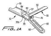
本開示の外科用器具は、概して、参照番号10によって示され、図1を参照すると、ハンドル部分20と、ハンドル部分から遠位に延びる内視鏡または細長いチューブ状部分30と、エンドエフェクタ40とを含む。エンドエフェクタ40は、細長い部分30の遠位部分31から延びる。回転ノブ22が提供され得ることにより、内視鏡部分30および取付けられたエンドエフェクタ40を、内視鏡部分30の長手方向の軸の周りで回転させ、これにより、エンドエフェクタ40を再配向する。 The surgical instrument of the present disclosure is generally indicated by
エンドエフェクタ40は、一対の顎部50、60を含み、これらの顎部は、組織把持器として機能し、開放して間隔が離れる位置と、閉鎖して近接する位置との間の動きのために旋回可能に搭載され、これにより、後述する態様において組織を捕捉する。図示した実施形態では、顎部50、60の両方が開放位置と閉鎖位置との間で動くが、顎部のうちの一方が固定し得、もう一方の顎部が開放位置と閉鎖位置との間で可動であり得ることもまた企図される。顎部50、60は、その把持機能を強化するために、その外周の周りに複数の歯を有し得る。
図1、図1A、および図2を参照すると、顎部50は、カムスロット52と、旋回穴54とを含む。同様に、顎部60は、カムスロット62と、旋回穴64とを含む。細長い組織プローブ70は、内視鏡部分30内にスライド可能に搭載される。より具体的には、プローブ70は、シース80内に固定され、シース80は、内視鏡部分30内の管腔内にスライド可能に搭載され、内視鏡部分30の管腔の遠位の開口部33を通して抜け出る。シース80は、横向きの支柱または杭82、84を含み、支柱または杭82、84は、それぞれ、顎部50、60のカムスロット52、62と係合する。したがって、後述されるハンドル機構によるシース80の動きは、シース80と同様に、収納されたプローブ70を遠位に動かす。内視鏡部分30は、平行アーム37、39を有するヨーク36内で終端し、平行アーム37、39は、それぞれ、内向きに延びる支柱38a、38bを有する。支柱38a、38bは、それぞれ、顎部50、60の旋回穴54、64と係合する。アーム37、39の長手方向スロット35a、35bは、シース80のスライドする動きに適応するように、シース80の支柱82および84を受取る。プローブ70は、好ましくは、シース80の遠位端で終端するが、代わりに、プローブ70は、シース80から突出するように、シース80の遠位端の遠位で終端することもあり得る。 With reference to FIGS. 1, 1 A, and 2, the
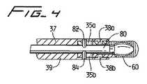
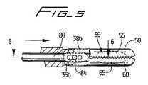
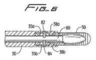
顎部50および60は、それぞれ、空洞55、65を有し、これらの空洞は、図示的には、実質的に楕円の形状であり、標的の組織を捕捉するように寸法が決められ、構成される。閉鎖位置において、空洞55、65は、閉鎖した空洞59を形成し(図5)、閉鎖した空洞59は、照明プローブ(例えば光ファイバー)が利用される場合、空洞59内の組織試料の照明を強化するための外光を遮断し得る。示されるような空洞59は、実質的に卵形の構成を有するが、例えば、球状、カップ形状、その他など、組織を捕捉し保持する空洞のための他の構成もまた意図している。 The
シース80の動きは、顎部50、60を開閉するように機能する。より具体的には、シース80の動きは、収納されて取付けられたプローブ70を図1Aの後退位置から図5および図6の前進位置まで動かし、また、カムスロット52、62内に係合したシース80の横向きの支柱82、84が、アーム37、39の支柱またはピン38a、38bの周りで顎部50、60をカム作用させて互いの方へ向かうように、顎部50、60を閉鎖位置に動かす。支柱82、84はまた、アーム37、39の長手方向スロット35a、35b内で遠位に動く。この態様において、顎部50、60が空洞59内の組織を捕捉するように閉鎖される場合、プローブ70は、その前進位置にあることにより、空洞内に捕捉および保持された組織試料を照明し、画像化し、診断し、そして/または処置する。しかるに、プローブ70のその動作位置への前進は、顎部の閉鎖に伴って自動的に生じる。言い換えると、顎部50、60の閉鎖は、組織プローブ70を、顎部の空洞内に収納された標的の組織に隣接した前進位置に自動的に前進させる。プローブ70は、一実施形態において、光ファイバーバンドルの形態にある。あるいは、プローブ70は、デジタルセンサであり得る。プローブはまた、2つ以上の機能を実行する多機能プローブであり得る。例えば、プローブは、照明および可視化の両方、または、照明および検出の両方を実行し得る。照明および可視化の両方を実行するために、プローブは、例えば、照明用のLEDと、何らかの形態の共焦点またはカメラとを有し得る。プローブは、有線または無線で接続され得、デバイスそれ自体から、または、一体化された手術室システム(コンピュータ/TVモニタ、外科用ナビゲーションシステム、その他)を使用することによって、情報がアクセスされ得る。 The movement of the
プローブ70がシース80の後退によって後退させられる場合、顎部50、60のカムスロット52、62内での横向きの支柱82、84の係合が顎部50、60を逆方向に動かすことに起因して、顎部50、60は、その開放位置に戻るように動かさる。支柱82、84は、内視鏡部分30の長手方向スロット35a、35b内で近位に動くことに留意する。 When the
前進位置と後退位置との間でのプローブ70のスライドする動きは、図3に示されるように、ハンドル部分20の旋回可能なハンドル24とのシース80の動作可能な接続によって達成される。つまり、旋回可能なハンドルまたはトリガ24のヨーク25は、接続ブロック29を介して、シース80の近位端81にしっかりと固定される。近位方向におけるハンドル24の旋回する(つまり、固定ハンドル27に向かう)動きは、シース80および取付けられたプローブ70を遠位に前進させる。シース80が前進させられると、横向きの支柱82、84は、内視鏡部分30のアーム37、39の長手方向スロット35a、35b内で遠位に前進し、また、顎部50、60とそれぞれのカムスロット52、62との係合に起因して、顎部50、60を閉鎖位置へカム作用させる。プローブ70は、図3に示されるように、可撓性であり、ループ部分72になるように形成され得、前進させられるといくらか真っ直ぐになることに留意する。上記のように、プローブ70の前進位置において、顎部50、60は、組織試料のための閉鎖した空洞を形成し、次いで、プローブ70は、組織を照明し、画像化し、診断し、そして/または処置するために利用され得る。 The sliding movement of the
外科手順におけるプローブ70の使用後、器具10は、閉鎖位置に維持された顎部50、60を有して、アクセスポートを通して引き出され得、顎部50、60のそれぞれの空洞55、65によって形成された空洞59内に囲繞された組織試料を引き出す。 After use of the
例えば、プローブ70のインサイチュ診断作用の後など、試料を外科部位内における顎部から解放することが所望される場合、顎部50、60は、ハンドル24がその元来のより遠位の位置に復帰することによって、開放され得る。つまり、ハンドル24のその遠位の位置への復帰は、シース80および取付けられたプローブ70を後退させる(近位に動かす)。 For example, if it is desired to release the sample from the jaw within the surgical site, such as after in-situ diagnostic action of the
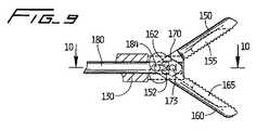
図7〜図10の代替の実施形態において、内視鏡部分のアーム上の横向きの支柱の代わりに、のぞき穴ヒンジ170が提供されることを除いて、図1〜図6の実施形態に類似する把持機構が提供される。より具体的には、顎部150および160は、顎部50および60と同一であり、カムスロット152、162と、旋回穴154、164とを有する。顎部150および160はまた、図1の器具の空洞55および65と同様の空洞155、165を有し、空洞155、165は、閉鎖される場合、組織の捕捉用または保持用の空洞を形成する。顎部の旋回穴と係合するための、内視鏡部分のアーム上の横向きの支柱の代わりに、内視鏡部分130が、のぞき穴ヒンジ170の横向きの支柱171、173を受取るための、ヨーク136のアーム137、139上の開口部131a、131bを有することを除いて、内視鏡部分130はまた、図1の内視鏡部分30と同一である。ヒンジ170は開口部172を有し、開口部172を通して、プローブ170およびシース180が通過する。ヒンジ170はまた、顎部150、160のための旋回点を形成し、顎部150、160の両側を所定の位置に保持する。 7-10 is similar to the embodiment of FIGS. 1-6 except that a
器具ハンドルの作動がシース180を遠位に前進させることにより、顎部150、160のそれぞれ、横向きの支柱182、184とカムスロット152、162との係合を介して、顎部150、160を閉鎖位置へカム作用させることにおいて、図7〜図10の把持用顎部は、器具10と同様に動作する。横向きの支柱182、184は、アーム137、139の長手方向スロット135a、135b内で遠位にスライドする。顎部50、60を閉鎖するシース180の前進は、閉鎖した顎部150、160の空洞155、165によって形成される空洞内での使用のために、取付けられたプローブ170を遠位に運ぶ。しかるに、図1の実施形態におけるように、閉鎖位置への顎部150、160の動きと、前進位置へのプローブ170(およびシース180)の動きとは、実質的に同時に起こり得る。プローブ170およびシース180は、本明細書において説明したプローブ70およびシース80と同一の形態にあり得ることに留意する。 Actuation of the instrument handle advances
図1の実施形態におけるように、顎部150、160を開放するために、ハンドルがその遠位の位置に復帰させられ、それによって、シース80および取付けられたプローブ70を近位に動かし、これによって、横向きの支柱182、184は、長手方向スロット135a、135b内で近位に進行し、横向きの支柱182、184の、カムスロット152、162との係合に起因して、顎部150、160を開放位置へ向かわせる。 As in the embodiment of FIG. 1, in order to open the
理解され得るように、前述の実施形態におけるプローブの送達は、器具の顎部が閉鎖位置に動かされると、自動的に達成される。 As can be appreciated, the delivery of the probe in the foregoing embodiment is accomplished automatically when the instrument jaws are moved to the closed position.
好ましい実施形態において、プローブ70(または170)は、約3mm以下の直径を有するが、他の寸法もまた意図している。プローブは、例えば、共焦点蛍光顕微鏡プローブ、近赤外ラマン分光プローブ、自己蛍光プローブ、色素支援(dye assisted)蛍光プローブ、その他であり得る。それによって、外科手順の期間中に、組織が診断され、照明され、画像化され、そして/または処置される。プローブの前進は、顎部空洞55、65(または顎部空洞155、165)によって形成される空洞内に収納される標的の組織と隣接して、また所望される場合は、標的の組織と接触して、プローブを配置する。 In a preferred embodiment, the probe 70 (or 170) has a diameter of about 3 mm or less, although other dimensions are also contemplated. The probe can be, for example, a confocal fluorescent microscope probe, a near infrared Raman spectroscopic probe, an autofluorescent probe, a dye assisted fluorescent probe, and the like. Thereby, tissue is diagnosed, illuminated, imaged and / or treated during the surgical procedure. The advancement of the probe is adjacent to the target tissue contained in the cavity formed by the
プローブおよびシースは、いくつかの実施形態において、シースによって包囲されるファイバーバンドルの形態にあり得る。そのような実施形態において、または、プローブがシース内に囲繞されるか、もしくはシース内に位置を決められる(シースに取付けられる)他の実施形態において、シースは、顎部を開放位置と閉鎖位置との間で動かす(例えば旋回させる)ために、横向きの支柱または他の構造を収納する。プローブがシース内に収納されない他の実施形態において、プローブは、顎部と係合し、かつ顎部を開放位置と閉鎖位置との間で動かす(例えば旋回させる)ために、横向きの支柱または他の構造を有し得る。 The probe and sheath can in some embodiments be in the form of a fiber bundle surrounded by the sheath. In such embodiments, or in other embodiments in which the probe is enclosed in or positioned within (attached to) the sheath, the sheath opens the jaws to the open and closed positions. Houses sideways struts or other structures for movement (e.g., swiveling) between. In other embodiments in which the probe is not housed within the sheath, the probe is a side-to-side strut or other for engaging the jaw and moving (eg, pivoting) the jaw between an open position and a closed position. The structure may be
ピン/カムのスロット配列が顎部を閉鎖するように示されているが、顎部を開閉することを達成するための他の構造もまた意図していることが理解されよう。また、実質的に平行の動きにおいて、顎部を開放位置と閉鎖位置との間で動かすための構造も提供され得る。 Although a pin / cam slot arrangement is shown to close the jaw, it will be understood that other structures for accomplishing opening and closing the jaw are also contemplated. A structure for moving the jaw between an open position and a closed position in a substantially parallel motion may also be provided.
プローブは、生検用の顎部、他の顎部構成と同様の歯を有するかまたは有しない把持用の顎部とともに使用され得る。上記のように、顎部は、異なる形状の空洞を有し得る。また、閉鎖した空洞を形成するように示されているが、部分的に開放した空洞もまた意図している。 The probe can be used with biopsy jaws, gripping jaws with or without teeth similar to other jaw configurations. As described above, the jaws can have differently shaped cavities. Also, although shown to form a closed cavity, a partially open cavity is also contemplated.
顎部およびプローブの動きのためのアクチュエータは、トリガの形態において示されているが、他のアクチュエータもまた意図している。 Actuators for jaw and probe movement are shown in the form of triggers, but other actuators are also contemplated.
使用に際して、器具は、組織の把持、および、顎部空洞において位置を決められた標的の組織の診断、照明、画像化および/または処置を可能にする。つまり、デバイスは、光ファイバー、共焦点、光トモグラフィー、その他などの可視化プローブと一体化された外科用把持器を提供し得る。顎部は、ある種の光/画像化技術を有した調査のために、閉じ込められた空間内の組織資料を囲繞し得る一方、組織試料を外光から保護する。 In use, the instrument allows for the grasping of tissue and diagnosis, illumination, imaging and / or treatment of target tissue located in the jaw cavity. That is, the device may provide a surgical grasper that is integrated with a visualization probe such as optical fiber, confocal, optical tomography, etc. The jaws can surround tissue material in a confined space for investigation with certain light / imaging techniques while protecting the tissue sample from external light.
蛍光の場合において、作業空間および体積は、組織を顎部空洞の中に閉じ込めることによって低減され、このことは、より小さい体積において、組織を刺激し、可視化する能力を提供する。また、単一の器具内において、単一のポートを通して、白色光(通常の腹腔鏡)および蛍光(顎部カップによって形成される空洞内で局所的に)の同時可視化も可能であり得る。 In the case of fluorescence, the working space and volume are reduced by confining the tissue within the jaw cavity, which provides the ability to stimulate and visualize the tissue in a smaller volume. It may also be possible to simultaneously visualize white light (normal laparoscope) and fluorescence (locally within the cavity formed by the jaw cup) through a single port within a single instrument.
理解され得るように、プローブは、いくつかの実施形態において、顎部が開放位置にある場合における体腔内のみならず、顎部が閉鎖位置にある場合における顎部空洞の中の閉じ込められた空間内においても、照明、画像化、診断、および/または処理のために利用され得る。 As can be appreciated, the probe may, in some embodiments, be confined within the body cavity when the jaw is in the open position, as well as within the jaw cavity when the jaw is in the closed position. Within, it can be utilized for illumination, imaging, diagnosis, and / or processing.
腹腔内において示されているが、器具は、身体の他の領域において使用され得る。 Although shown in the abdominal cavity, the instrument can be used in other areas of the body.
本明細書において開示された実施形態に対して、様々な改変がなされ得ることが理解されよう。それゆえ、上記の説明は、限定的にではなく、単に好ましい実施形態の例示として解釈されるべきである。当業者は、本明細書に添付の特許請求の範囲の意図および範囲内において、他の実施形態を想起するであろう。 It will be understood that various modifications may be made to the embodiments disclosed herein. Therefore, the above description should not be construed as limiting, but merely as exemplifications of preferred embodiments. Those skilled in the art will envision other embodiments within the scope and spirit of the claims appended hereto.
10 外科用器具
20 ハンドル部分
22 回転ノブ
24 ハンドル
25、36、136 ヨーク
27 固定ハンドル
29 接続ブロック
30、130 内視鏡部分
37、39、137、139 アーム
40 エンドエフェクタ
50、60、150、160 顎部
52、62、152、162 カムスロット
54、64、154、164 旋回穴
55、59、65、155、165 空洞
70、170 プローブ
80、180 シース
82、84、171、173、182、184 横向きの支柱
170 ヒンジDESCRIPTION OF
Claims (20)
Translated fromJapaneseハンドル部分と、
該ハンドル部分から遠位に延びている細長い本体部分と、
該細長い本体部分の遠位に延びているエンドエフェクタであって、第1の位置と第2の位置との間で可動なエンドエフェクタと、
該細長い部分の中に可動なように位置を決められている細長い組織プローブと
を備え、該プローブは、後退位置と前進位置との間で可動であり、該プローブの動きは、該エンドエフェクタを該第1の位置から該第2の位置まで動かす、外科用器具。A surgical instrument for a minimally invasive surgical procedure, the surgical instrument comprising:
A handle part,
An elongated body portion extending distally from the handle portion;
An end effector extending distally of the elongate body portion, the end effector being movable between a first position and a second position;
An elongate tissue probe positioned movably within the elongate portion, the probe being movable between a retracted position and an advanced position, wherein movement of the probe causes the end effector to move A surgical instrument that moves from the first position to the second position.
アクチュエータと、
該アクチュエータから遠位に延びている細長い部分と、
該細長い部分の遠位に延びている第1の顎部および第2の顎部であって、該顎部のうちの少なくとも一方は、該顎部内に組織受取り用空洞が形成されている、第1の顎部および第2の顎部と、
プローブであって、該第1の顎部および該第2の顎部が閉鎖位置にある場合に該空洞内に位置を決められた、組織の画像化、診断、処置のうちの1つ以上のために、該細長い部分の中に可動なように位置を決められている、プローブと
を備えている、外科用器具。A surgical instrument for minimally invasive surgical procedures,
An actuator,
An elongate portion extending distally from the actuator;
A first jaw and a second jaw extending distally of the elongate portion, wherein at least one of the jaws has a tissue receiving cavity formed in the jaw; One jaw and a second jaw;
One or more of tissue imaging, diagnosis, and treatment positioned within the cavity when the first jaw and the second jaw are in a closed position; And a probe positioned for movement within the elongated portion.
少なくとも1つの可動な顎部を有する把持器具と、
該プローブから該組織にエネルギーを適用するための手段と
を備え、該少なくとも1つの可動な顎部は、標的の組織に隣接して位置を決められるように構成されており、
該少なくとも1つの顎部は、閉鎖された場合に空洞を形成することと、組織プローブを標的の組織に自動的に送達することとを行うように構成されている、システム。A system for performing minimally invasive surgery,
A grasping device having at least one movable jaw;
Means for applying energy from the probe to the tissue, and wherein the at least one movable jaw is configured to be positioned adjacent to the target tissue;
The system, wherein the at least one jaw is configured to form a cavity when closed and to automatically deliver a tissue probe to a target tissue.
Applications Claiming Priority (4)
| Application Number | Priority Date | Filing Date | Title |
|---|---|---|---|
| US31528010P | 2010-03-18 | 2010-03-18 | |
| US61/315,280 | 2010-03-18 | ||
| US13/028,289US9737320B2 (en) | 2010-03-18 | 2011-02-16 | Surgical grasper with integrated probe |
| US13/028,289 | 2011-02-16 |
Publications (1)
| Publication Number | Publication Date |
|---|---|
| JP2011194225Atrue JP2011194225A (en) | 2011-10-06 |
Family
ID=44121522
Family Applications (1)
| Application Number | Title | Priority Date | Filing Date |
|---|---|---|---|
| JP2011051864ACeasedJP2011194225A (en) | 2010-03-18 | 2011-03-09 | Surgical grasper with integrated probe |
Country Status (5)
| Country | Link |
|---|---|
| US (2) | US9737320B2 (en) |
| EP (1) | EP2366344B1 (en) |
| JP (1) | JP2011194225A (en) |
| CN (1) | CN102232858B (en) |
| AU (1) | AU2011200826A1 (en) |
Families Citing this family (13)
| Publication number | Priority date | Publication date | Assignee | Title |
|---|---|---|---|---|
| US9737320B2 (en) | 2010-03-18 | 2017-08-22 | Covidien Lp | Surgical grasper with integrated probe |
| USD668337S1 (en)* | 2010-11-15 | 2012-10-02 | Erbe Elektromedizin Gmbh | Electro-surgical clamp and cutting device |
| US9168050B1 (en)* | 2011-03-24 | 2015-10-27 | Cambridge Endoscopic Devices, Inc. | End effector construction |
| WO2014186319A1 (en)* | 2013-05-13 | 2014-11-20 | The Johns Hopkins University | Encapsulated cryoprobe for flexible bronchoscope |
| KR101656944B1 (en)* | 2013-10-16 | 2016-09-19 | 국립암센터 | Endoscopic Injection Apparatus |
| US9848935B2 (en)* | 2015-05-27 | 2017-12-26 | Covidien Lp | Surgical instruments including components and features facilitating the assembly and manufacturing thereof |
| US20160361051A1 (en)* | 2015-06-09 | 2016-12-15 | Boston Scientific Scimed, Inc. | System for the parallel delivery of an element into the esophageal mucosa |
| KR101835043B1 (en)* | 2015-11-03 | 2018-03-08 | (주) 인텍플러스 | Dissection tool And Dissection system |
| EP3373831B1 (en)* | 2015-11-13 | 2024-01-03 | Intuitive Surgical Operations, Inc. | Push-pull stapler with two degree of freedom wrist |
| CN113164183B (en)* | 2018-11-30 | 2024-05-24 | 奥林巴斯株式会社 | Gripping mechanism |
| US11883051B2 (en) | 2020-08-24 | 2024-01-30 | Covidien Lp | Hollow graspers |
| USD971404S1 (en)* | 2020-09-29 | 2022-11-29 | Livsmed Inc. | Jaw for surgical instrument |
| USD950058S1 (en) | 2020-10-14 | 2022-04-26 | Covidien Lp | Common component for a jaw assembly |
Citations (6)
| Publication number | Priority date | Publication date | Assignee | Title |
|---|---|---|---|---|
| WO1999030622A2 (en)* | 1997-12-17 | 1999-06-24 | Surgical Insight, Inc. | Low profile endoscopic surgical instruments |
| JPH11509132A (en)* | 1996-05-07 | 1999-08-17 | スペクトラサイエンス,インコーポレイティド | Optical biopsy forceps |
| US6149607A (en)* | 1998-08-04 | 2000-11-21 | Endonetics, Inc. | Multiple sample biopsy device |
| JP2002505904A (en)* | 1998-03-09 | 2002-02-26 | スペクトラサイエンス,インコーポレイティド | Optical biopsy forceps system and tissue sample collection method |
| US20020058961A1 (en)* | 2000-10-16 | 2002-05-16 | Aguilar Amiel R. | Catheter |
| JP2009543663A (en)* | 2006-07-18 | 2009-12-10 | トラスティーズ オブ ボストン ユニバーシティ | Apparatus with integrated multi-fiber optical probe and method of use |
Family Cites Families (41)
| Publication number | Priority date | Publication date | Assignee | Title |
|---|---|---|---|---|
| US3895636A (en)* | 1973-09-24 | 1975-07-22 | William Schmidt | Flexible forceps |
| US4249533A (en)* | 1977-05-16 | 1981-02-10 | Olympus Optical Co., Ltd. | Laser knife |
| US4557255A (en)* | 1983-08-22 | 1985-12-10 | Goodman Tobias M | Ureteroscope |
| US4721116A (en)* | 1985-06-04 | 1988-01-26 | Schintgen Jean Marie | Retractable needle biopsy forceps and improved control cable therefor |
| US4598699A (en)* | 1985-06-10 | 1986-07-08 | Garren Lloyd R | Endoscopic instrument for removing stomach insert |
| US4869268A (en)* | 1987-05-14 | 1989-09-26 | Inbae Yoon | Multi-functional instruments and stretchable ligating and occluding devices |
| US4788966A (en)* | 1987-05-14 | 1988-12-06 | Inbae Yoon | Plug for use in a reversible sterilization procedure |
| US4887612A (en)* | 1988-04-27 | 1989-12-19 | Esco Precision, Inc. | Endoscopic biopsy forceps |
| US5226908A (en)* | 1989-12-05 | 1993-07-13 | Inbae Yoon | Multi-functional instruments and stretchable ligating and occluding devices |
| US5919202A (en)* | 1989-12-05 | 1999-07-06 | Yoon; Inbae | Surgical instrument with jaws and movable internal needle and method for use thereof |
| US5082000A (en)* | 1990-11-29 | 1992-01-21 | Applied Medical Technology, Inc. | Biopsy forceps with calde controlled jaws |
| US5542432A (en)* | 1992-02-18 | 1996-08-06 | Symbiosis Corporation | Endoscopic multiple sample bioptome |
| US5620459A (en)* | 1992-04-15 | 1997-04-15 | Microsurge, Inc. | Surgical instrument |
| US5318589A (en)* | 1992-04-15 | 1994-06-07 | Microsurge, Inc. | Surgical instrument for endoscopic surgery |
| US5238002A (en)* | 1992-06-08 | 1993-08-24 | C. R. Bard, Inc. | Disposable biopsy forceps |
| US5373854A (en)* | 1993-07-15 | 1994-12-20 | Kolozsi; William Z. | Biopsy apparatus for use in endoscopy |
| CA2172129A1 (en)* | 1993-09-20 | 1995-04-06 | Bruce H. Diamond | Multiple biopsy sampling device |
| US5840044A (en)* | 1993-09-30 | 1998-11-24 | Boston Scientific Corporation | Multiple biopsy sampling forceps |
| US5871453A (en)* | 1994-02-08 | 1999-02-16 | Boston Scientific Corporation | Moveable sample tube multiple biopsy sampling device |
| US5505730A (en)* | 1994-06-24 | 1996-04-09 | Stuart D. Edwards | Thin layer ablation apparatus |
| US5562102A (en)* | 1994-11-21 | 1996-10-08 | Taylor; Thomas V. | Multiple biopsy device |
| US5575806A (en)* | 1995-03-10 | 1996-11-19 | Nakao; Naomi | Biopsy forceps with tissue ejection means |
| US5746770A (en)* | 1995-11-22 | 1998-05-05 | Zeitels; Jerrold Roy | Endoscopic retriever |
| US5762069A (en)* | 1995-12-29 | 1998-06-09 | Akos Biomedical, Inc. | Multiple sample biopsy forceps |
| US5843000A (en)* | 1996-05-07 | 1998-12-01 | The General Hospital Corporation | Optical biopsy forceps and method of diagnosing tissue |
| US6296608B1 (en)* | 1996-07-08 | 2001-10-02 | Boston Scientific Corporation | Diagnosing and performing interventional procedures on tissue in vivo |
| US5820630A (en)* | 1996-10-22 | 1998-10-13 | Annex Medical, Inc. | Medical forceps jaw assembly |
| US5895361A (en)* | 1997-02-14 | 1999-04-20 | Symbiosis Corporation | Esophageal biopsy jaw assembly and endoscopic instrument incorporating the same |
| WO1998040015A2 (en) | 1997-03-13 | 1998-09-17 | Biomax Technologies, Inc. | Catheters and endoscopes comprising optical probes and bioptomes and methods of using the same |
| JPH11225951A (en)* | 1998-02-17 | 1999-08-24 | Olympus Optical Co Ltd | Treatment tool for endoscope |
| US5944728A (en)* | 1998-04-23 | 1999-08-31 | Boston Scientific Corporation | Surgical retrieval basket with the ability to capture and release material |
| US6139508A (en)* | 1998-08-04 | 2000-10-31 | Endonetics, Inc. | Articulated medical device |
| US7169167B2 (en)* | 2001-12-04 | 2007-01-30 | Scimed Life Systems, Inc. | Endoscopic apparatus and method |
| WO2003105674A2 (en)* | 2002-06-18 | 2003-12-24 | Tyco Healthcare Group, Lp | Tissue removal device |
| US7775989B2 (en)* | 2003-09-03 | 2010-08-17 | Granit Medical Innovations, Llc | Needle biopsy forceps with integral sample ejector |
| US7052489B2 (en)* | 2003-12-05 | 2006-05-30 | Scimed Life Systems, Inc. | Medical device with deflecting shaft and related methods of manufacture and use |
| EP1863388A1 (en) | 2005-03-03 | 2007-12-12 | Granit Medical Innovations, LLC | Needle biopsy forceps with integral sample ejector |
| US20070135686A1 (en)* | 2005-12-14 | 2007-06-14 | Pruitt John C Jr | Tools and methods for epicardial access |
| US8114121B2 (en)* | 2006-06-22 | 2012-02-14 | Tyco Healthcare Group Lp | Tissue vitality comparator with light pipe with fiber optic imaging bundle |
| EP2265184A1 (en) | 2008-03-06 | 2010-12-29 | Trustees of Boston University | Low cost disposable medical forceps to enable a hollow central channel for various functionalities |
| US9737320B2 (en) | 2010-03-18 | 2017-08-22 | Covidien Lp | Surgical grasper with integrated probe |
- 2011
- 2011-02-16USUS13/028,289patent/US9737320B2/ennot_activeExpired - Fee Related
- 2011-02-25AUAU2011200826Apatent/AU2011200826A1/ennot_activeAbandoned
- 2011-03-09JPJP2011051864Apatent/JP2011194225A/ennot_activeCeased
- 2011-03-17EPEP11250328.9Apatent/EP2366344B1/enactiveActive
- 2011-03-18CNCN201110068515.1Apatent/CN102232858B/ennot_activeExpired - Fee Related
- 2017
- 2017-08-14USUS15/676,116patent/US10864002B2/enactiveActive
Patent Citations (6)
| Publication number | Priority date | Publication date | Assignee | Title |
|---|---|---|---|---|
| JPH11509132A (en)* | 1996-05-07 | 1999-08-17 | スペクトラサイエンス,インコーポレイティド | Optical biopsy forceps |
| WO1999030622A2 (en)* | 1997-12-17 | 1999-06-24 | Surgical Insight, Inc. | Low profile endoscopic surgical instruments |
| JP2002505904A (en)* | 1998-03-09 | 2002-02-26 | スペクトラサイエンス,インコーポレイティド | Optical biopsy forceps system and tissue sample collection method |
| US6149607A (en)* | 1998-08-04 | 2000-11-21 | Endonetics, Inc. | Multiple sample biopsy device |
| US20020058961A1 (en)* | 2000-10-16 | 2002-05-16 | Aguilar Amiel R. | Catheter |
| JP2009543663A (en)* | 2006-07-18 | 2009-12-10 | トラスティーズ オブ ボストン ユニバーシティ | Apparatus with integrated multi-fiber optical probe and method of use |
Also Published As
| Publication number | Publication date |
|---|---|
| EP2366344B1 (en) | 2020-02-19 |
| US20110230910A1 (en) | 2011-09-22 |
| EP2366344A3 (en) | 2015-06-03 |
| AU2011200826A1 (en) | 2011-10-06 |
| US9737320B2 (en) | 2017-08-22 |
| US10864002B2 (en) | 2020-12-15 |
| CN102232858B (en) | 2015-05-20 |
| CN102232858A (en) | 2011-11-09 |
| EP2366344A2 (en) | 2011-09-21 |
| US20170340342A1 (en) | 2017-11-30 |
Similar Documents
| Publication | Publication Date | Title |
|---|---|---|
| US10864002B2 (en) | Surgical grasper with integrated probe | |
| US7261728B2 (en) | Biopsy forceps device and method | |
| US20110060188A1 (en) | Low cost disposable medical forceps to enable a hollow central channel for various functionalities | |
| JP5164553B2 (en) | Surgical treatment device | |
| US7060024B2 (en) | Apparatus for guiding an instrument used with an endoscope | |
| US7060025B2 (en) | Method for controlling position of medical instruments | |
| JP5407036B2 (en) | Treatment endoscope | |
| EP2598018B1 (en) | Surgical apparatus | |
| JP4169142B2 (en) | Endoscopic surgical device | |
| EP1614391A1 (en) | Suture manipulating instrument particularly useful with endoscopes | |
| US11457941B2 (en) | Articulable endoscopic instruments | |
| JP6290376B2 (en) | Surgeon-controlled endoscopic device | |
| US20170007294A1 (en) | Endoscopic surgical device, treatment tool, and guide member | |
| JP2023126438A (en) | Devices and methods for tissue retraction | |
| CN205831834U (en) | A kind of activity pincers for puncturing | |
| KR100964082B1 (en) | Biopsy forceps for endoscopy | |
| KR20120007107A (en) | Multi Direction Retractor | |
| US9549661B2 (en) | Medical device actuation systems and related methods of use | |
| US20170007100A1 (en) | Endoscopic surgical device, endoscope, and endoscope operating tool | |
| JP4075310B2 (en) | Intracavity TV camera | |
| CN118512219A (en) | Biopsy sampler | |
| CN209172245U (en) | A kind of endoscope attachment handle of one-handed performance | |
| KR102172603B1 (en) | Endoscopic instrument and polyp retrieving instrument of attached to endoscopic instrument | |
| CA2733272A1 (en) | Surgical grasper with integrated probe | |
| US10542869B2 (en) | Endoscopic surgical device and guide device |
Legal Events
| Date | Code | Title | Description |
|---|---|---|---|
| A621 | Written request for application examination | Free format text:JAPANESE INTERMEDIATE CODE: A621 Effective date:20140307 | |
| A977 | Report on retrieval | Free format text:JAPANESE INTERMEDIATE CODE: A971007 Effective date:20141009 | |
| A131 | Notification of reasons for refusal | Free format text:JAPANESE INTERMEDIATE CODE: A131 Effective date:20141028 | |
| A521 | Written amendment | Free format text:JAPANESE INTERMEDIATE CODE: A523 Effective date:20150121 | |
| A01 | Written decision to grant a patent or to grant a registration (utility model) | Free format text:JAPANESE INTERMEDIATE CODE: A01 Effective date:20150609 | |
| A045 | Written measure of dismissal of application | Free format text:JAPANESE INTERMEDIATE CODE: A045 Effective date:20151022 |