JP2011194155A - Infusion pump - Google Patents
Infusion pumpDownload PDFInfo
- Publication number
- JP2011194155A JP2011194155AJP2010066891AJP2010066891AJP2011194155AJP 2011194155 AJP2011194155 AJP 2011194155AJP 2010066891 AJP2010066891 AJP 2010066891AJP 2010066891 AJP2010066891 AJP 2010066891AJP 2011194155 AJP2011194155 AJP 2011194155A
- Authority
- JP
- Japan
- Prior art keywords
- cassette
- power
- infusion
- battery
- infusion pump
- Prior art date
- Legal status (The legal status is an assumption and is not a legal conclusion. Google has not performed a legal analysis and makes no representation as to the accuracy of the status listed.)
- Ceased
Links
- 238000001802infusionMethods0.000titleclaimsabstractdescription97
- 238000001514detection methodMethods0.000claimsdescription16
- 239000000126substanceSubstances0.000claimsdescription8
- 239000003814drugSubstances0.000abstractdescription6
- 229940079593drugDrugs0.000abstractdescription6
- 238000006243chemical reactionMethods0.000abstractdescription2
- 239000007788liquidSubstances0.000description12
- 239000000243solutionSubstances0.000description11
- 230000002572peristaltic effectEffects0.000description7
- 230000002354daily effectEffects0.000description3
- 238000010586diagramMethods0.000description3
- 230000004397blinkingEffects0.000description2
- 230000003203everyday effectEffects0.000description2
- 238000012840feeding operationMethods0.000description2
- 230000006870functionEffects0.000description2
- 238000000034methodMethods0.000description2
- 229920003002synthetic resinPolymers0.000description2
- 239000000057synthetic resinSubstances0.000description2
- HBBGRARXTFLTSG-UHFFFAOYSA-NLithium ionChemical compound[Li+]HBBGRARXTFLTSG-UHFFFAOYSA-N0.000description1
- PXHVJJICTQNCMI-UHFFFAOYSA-NNickelChemical compound[Ni]PXHVJJICTQNCMI-UHFFFAOYSA-N0.000description1
- 229920000122acrylonitrile butadiene styrenePolymers0.000description1
- 238000004891communicationMethods0.000description1
- 230000000694effectsEffects0.000description1
- 229920005669high impact polystyrenePolymers0.000description1
- 239000004797high-impact polystyreneSubstances0.000description1
- 238000003780insertionMethods0.000description1
- 230000037431insertionEffects0.000description1
- 239000004973liquid crystal related substanceSubstances0.000description1
- 229910001416lithium ionInorganic materials0.000description1
- 239000008155medical solutionSubstances0.000description1
- 229910000652nickel hydrideInorganic materials0.000description1
- 238000012545processingMethods0.000description1
- 230000001105regulatory effectEffects0.000description1
- 229920001169thermoplasticPolymers0.000description1
- 239000004416thermosoftening plasticSubstances0.000description1
- 239000002699waste materialSubstances0.000description1
Images


Landscapes
- Infusion, Injection, And Reservoir Apparatuses (AREA)
Abstract
Description
Translated fromJapanese本発明は、体内に薬液を注入するための輸液ポンプに係り、詳しくは、輸液チューブを回転ローラに押しつけることにより、該輸液チューブに蠕動様運動を与えて、チューブ内の液体を順次送液する輸液ポンプの改良に関するものである。 The present invention relates to an infusion pump for injecting a medical solution into the body. Specifically, by pressing the infusion tube against a rotating roller, the infusion tube is given a peristaltic motion to sequentially deliver the liquid in the tube. The present invention relates to an improvement of an infusion pump.
患者に対して、時間当たり薬液を決められた量だけ長時間かけて注入する輸液ポンプは広く使用されている。
このような輸液ポンプのうち、例えば、医療機関だけでなく、在宅でも使用できるようにコンパクトに形成したものが知られている(特許文献1参照)。
特許文献1の輸液ポンプは、外部から導入される薬液を通す可撓性チューブを着脱式のカセットに導く構成とされている。An infusion pump that infuses a patient with a predetermined amount of a drug solution per hour over a long period of time is widely used.
Among such infusion pumps, for example, one that is compactly formed so that it can be used not only at medical institutions but also at home is known (see Patent Document 1).
The infusion pump of Patent Document 1 is configured to guide a flexible tube through which a chemical solution introduced from the outside passes to a detachable cassette.
具体的には、該着脱式のカセットのケース内に可撓性の輸液チューブ(以下、「チューブ」と言う。)を導入し、ケース内でU字状に180度向きを変えて、該チューブを該ケース外部に導出する構成とされている。そして、このケースから一部露出させた上記チューブに対して、回転ローラを押しつけることにより、該チューブに蠕動様運動を与えて、チューブ内の薬液を順次送り出すようにされている。 Specifically, a flexible infusion tube (hereinafter referred to as “tube”) is introduced into the case of the detachable cassette, and the direction is changed to 180 degrees in a U shape within the case. Is derived to the outside of the case. Then, by pressing a rotating roller against the tube partially exposed from the case, a peristaltic motion is given to the tube to sequentially feed out the chemicals in the tube.
ところで、特許文献1の装置では、回転ローラを回転駆動するモータを備えており、このモータに直流電源を供給するために、乾電池を輸液ポンプに装填して用いている。そして、輸液ポンプによる輸液動作が停止しないようにするために、患者が、毎日乾電池を取り出して新しい乾電池に交換する必要がある。
そして、使用者の手間を省くため、すなわち、新しい電池を入れることにより、機器の電源を自動的にオンし、送液可能とする構成とされていた。
しかし、高齢者のような患者が、このような乾電池の交換作業を毎日行うことは、患者にとっては大きな負担になっている。By the way, in the apparatus of patent document 1, the motor which rotationally drives a rotating roller is provided, and in order to supply DC power to this motor, the dry cell is loaded and used for the infusion pump. And in order not to stop the infusion operation | movement by an infusion pump, a patient needs to take out a dry battery and replace | exchange for a new dry battery every day.
In order to save the user's trouble, that is, by inserting a new battery, the power supply of the device is automatically turned on to enable liquid feeding.
However, it is a heavy burden on the patient that a patient such as an elderly person performs such dry battery replacement work every day.
また、輸液ポンプは、乾電池による駆動に代えて、商用交流電源に接続して交流を直流に変換する電源アダプタを用いて駆動を行うことも可能であるが、商用交流電源の停電時や、電源アダプタのプラグが建物のコンセントから外れてしまうことがあり、その場合にも輸液ポンプの使用を確保するための内部電源として、輸液ポンプに対して乾電池を挿入することは必須である。
そして、電源アダプタを用いても、電源アダプタを通じては乾電池に対して充電することはできないので、輸液ポンプの輸液動作を停止しないようにして円滑に使用できるようにするために、上述したように毎日、前日に使用した乾電池を新しい乾電池に交換することが必要とされている。The infusion pump can also be driven by using a power adapter that converts AC to DC by connecting to a commercial AC power supply instead of driving by a dry battery. The adapter plug may come off from the outlet of the building, and even in that case, it is essential to insert a dry battery into the infusion pump as an internal power source for ensuring the use of the infusion pump.
Even if a power adapter is used, the battery cannot be charged through the power adapter. Therefore, in order to ensure smooth use without stopping the infusion operation of the infusion pump, as described above, Therefore, it is necessary to replace the battery used the previous day with a new battery.
また、従来の輸液ポンプでは、上記したように乾電池を輸液ポンプ内に挿入すると、輸液ポンプの主電源を自動的にオンする構造であるので、実際の送液をしなくても電池をいれただけで主電源がオンされ、消費電力に無駄が生じていた。
したがって、このような電力の無駄を省こうとすると、ケースに電源スイッチを別途設ける等しなければならず、その分使用者に操作の負担がかかる。In addition, in the conventional infusion pump, as described above, when the dry battery is inserted into the infusion pump, the main power source of the infusion pump is automatically turned on, so the battery can be inserted without actually sending the liquid. As a result, the main power supply was turned on, and power consumption was wasted.
Therefore, in order to eliminate such waste of electric power, it is necessary to separately provide a power switch on the case, and the operation is burdened on the user accordingly.
本発明は上記課題を解消するためになされたものであり、毎日の電池の交換作業をしなくても、確実に使用することができ、省電力を図ることができる輸液ポンプを提供することを目的とする。 The present invention has been made to solve the above-described problems, and provides an infusion pump that can be used reliably and can save power without performing daily battery replacement work. Objective.
本発明の輸液ポンプは、輸液チューブを有するカセットを着脱可能に装着した状態で使用する、薬液を送出するための輸液送り部と、該輸液送り部を駆動するための電源として繰り返して充電可能な電池と、前記輸液送り部を駆動するための電源として商用交流電源に接続して交流/直流変換し、前記電池に充電可能な電源アダプタと、前記輸液送り部を駆動するとともに、前記電源と接続された制御部と、前記カセットを装着すると前記輸液送り部へ供給する前記電源をオンするためのオン信号を前記制御部に送り、前記カセットを外すと前記輸液送り部へ供給する前記電源をオフするためのオフ信号を前記制御部に送る電源オンオフ操作部とを有することを特徴とする。 The infusion pump of the present invention is used in a state in which a cassette having an infusion tube is detachably mounted, and can be repeatedly charged as an infusion feed section for sending out a medicinal solution and a power source for driving the infusion feed section. Connected to a commercial AC power source as a power source for driving the battery and the infusion feeding part, and AC / DC converted, and a power adapter capable of charging the battery, driving the infusion feeding part, and connecting to the power source When the cassette is mounted, an on signal for turning on the power to be supplied to the infusion feeding portion is sent to the control portion, and when the cassette is removed, the power to be supplied to the infusion feeding portion is turned off. And a power on / off operation unit that sends an off signal to the control unit.
上記構成によれば、電池を輸液ポンプに装填したままで電池に自動的に充電することができ、電池の交換作業を不要にできる。すなわち、繰り返して充電可能な電池を輸液ポンプに装填したままで、この電池に対して自動的に充電することができるので、例えば患者や周囲の家族の人が電池の交換作業をする必要がなくなり、輸液ポンプの使用勝手が向上する。
しかも、電源オンオフは、新しく電池を装着することではなく、前記カセットを装着するタイミングで行うようにしたので、常時収納されている前記充電可能な電池の電源は、送液時にだけ使用されるようにすることができ、省電力を図ることができる。According to the said structure, a battery can be charged automatically, with the battery mounted in the infusion pump, and the replacement | exchange operation | work of a battery can be made unnecessary. In other words, the rechargeable battery can be charged automatically with the rechargeable battery loaded in the infusion pump, so that it is not necessary for the patient or a family member to replace the battery, for example. The usability of the infusion pump is improved.
In addition, since the power on / off is performed not at the time of newly installing the battery but at the timing of mounting the cassette, the power source of the rechargeable battery that is always stored is used only at the time of liquid feeding. And can save power.
好ましくは、前記電源オンオフ操作部は、前記カセットを装着することで移動し前記カセットを外すと逆に移動する突起部材と、前記カセットを装着して前記突起部材を移動することにより前記オン信号を前記制御部に送り、前記カセットを外して前記突起部材を逆に移動することにより前記オフ信号を前記制御部に送るスイッチと、を有することを特徴とする。
上記構成によれば、突起部材を移動するだけでスイッチを操作でき、簡単な構成でありながら制御部に対して電源のオン信号とオフ信号を供給できる。Preferably, the power on / off operation unit moves when the cassette is mounted and moves reversely when the cassette is removed, and moves the protrusion member when the cassette is mounted to move the on signal. A switch that sends the off signal to the control unit by removing the cassette and moving the protruding member in the reverse direction.
According to the above configuration, the switch can be operated only by moving the protruding member, and the power supply ON signal and OFF signal can be supplied to the control unit with a simple configuration.
好ましくは、前記制御部は、前記カセットを外して前記オフ信号が送られてから予め定めた待機時間を経過すると、前記電源を自動的にオフにすることを特徴とする。
上記構成によれば、例えば輸液チューブがからんだり捩じったりしてカセットを一旦外して再度装着しようとする場合に、電源をオンしたまま維持できるので電源がオフしてしまうのを防ぎ、再度最初からシーケンスを繰り返す必要が無いので、輸液ポンプの使用勝手が向上する。Preferably, the control unit automatically turns off the power when a predetermined waiting time elapses after the cassette is removed and the off signal is sent.
According to the above configuration, for example, when the infusion tube is entangled or twisted and the cassette is once removed and then remounted, it can be maintained while the power is on, so that the power is not turned off, Since it is not necessary to repeat the sequence from the beginning again, the usability of the infusion pump is improved.
好ましくは、前記カセットを着脱可能に収納するカセット収納部を有し、前記電源オンオフ操作部は、前記カセットが前記カセット収納部に対して正常に装着されているかを検出する検出センサを兼ねていることを特徴とする。
上記構成によれば、電源オンオフ操作部は、前記カセットがカセット収納部に対して正常に装着されているかを検出できる。Preferably, the apparatus has a cassette storage unit that detachably stores the cassette, and the power-on / off operation unit also serves as a detection sensor that detects whether the cassette is normally attached to the cassette storage unit. It is characterized by that.
According to the above configuration, the power on / off operation unit can detect whether or not the cassette is normally attached to the cassette storage unit.
本発明によれば、毎日の電池の交換作業をしなくても、確実に使用することができ、省電力を図ることができる輸液ポンプを提供することができる。 According to the present invention, it is possible to provide an infusion pump that can be used reliably and save power without performing daily battery replacement work.
以下に、本発明の好ましい実施形態を、図面を参照して詳しく説明する。
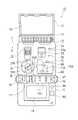
図1は、本発明の輸液ポンプのカセット収納部のカバー(透明)を閉じた概略斜視図であり、図2はそのカセット収納部のカバーを開いた状態を示す概略正面図、図3は輸液ポンプのカセット収納部のカバーを開き、カセットを収納した状態を示す概略斜視図である。
図1〜図3において、輸液ポンプ10は、例えば、略矩形の筐体としての本体11を有している。本体11は、前筐体49と後筐体44を有する。本体11は、輸液ポンプ10の構成物のケースであり、好ましくは、耐薬品性、耐衝撃性を有する熱可塑性合成樹脂、例えば、ハイインパクトスチロールやABS樹脂等で形成されている。Hereinafter, preferred embodiments of the present invention will be described in detail with reference to the drawings.
FIG. 1 is a schematic perspective view in which a cover (transparent) of a cassette housing part of the infusion pump of the present invention is closed, FIG. 2 is a schematic front view showing a state in which the cover of the cassette housing part is opened, and FIG. It is a schematic perspective view which shows the state which opened the cover of the cassette storage part of the pump, and accommodated the cassette.
1-3, the
図1に示すように、本体11は、本体11の上面側のほぼ半分程度の面積を閉めるように、開閉可能なカバー12を有しており、該カバー12を、ヒンジ13を中心として回動可能として開閉できるようにされている。このカバー12は、図示しない付勢手段、例えば、ヒンジ13の軸周りにトーションコイル等を配設することにより、図2と図3に示すように、常時開方向に付勢されている。カバー12を閉じて押し込むことにより、本体11側の図示しないラッチ等に係合されるようになっており、本体11の側部外縁に突出する解除ボタン16,16を、矢印方向に手指にて押し込むことにより、該ラッチ等が解除されるようになっている。 As shown in FIG. 1, the
図1の符号17は開始停止スイッチであり、図1において横方向に「停止―開始」のスライド操作をすることができる。符号18は液晶表示装置等で形成した表示部であり、運転状態や、後で説明する報知情報等を表示するようになっている。これらの他に、図示しないモード選択スイッチ等を備えることができる。
前筐体49には、例えば、発光ダイオードランプのような点灯手段による点灯表示部LPが、表示部18の付近に配置されている。この点灯表示部LPは、例えば点滅することにより警報内容を、例えば患者あるいは周囲の家族の人に目視で報知するようになっている。
また、前筐体49には、表示部18の付近にブザー88とスピーカ89が配置されている。ブザー88は警報内容を警報音で報知でき、スピーカ89は警報内容を音声で報知する機能を有する。
In the
Further, a
図2と図3に示すように、本体11からカバー12を開くと、カセット収納部15が露出するようになっている。カセット収納部15は、本体11の厚みの約半分程度の寸法で形成された空間であり、この空間であるカセット収納部15には、図3に示すように、輸液チューブ21を引きこみかつ導出するためのカセット20を着脱可能にセットすることができるようになっている。 As shown in FIGS. 2 and 3, when the
本体11のカセット収納部15上には、輸液送り部としてのロータユニット31と、閉塞検出部83が配置されている。本体11のカセット収納部15内には、駆動部としてのモータMが配置されている。ロータユニット31は、モータMを有しており、ロータユニット31はこのモータMの出力軸からの駆動力が、ロータユニット31に対して図示しないギア等を介して伝達されることにより、ロータユニット31が軸Lを中心にして回転する。
図2に示すように、このロータユニット31の外周には、例えば、4か所以上の図示例では5つのチューブ押圧部31Rが設けられており、ロータユニット31のチューブ押圧部31Rが図2の矢印方向に回転することにより、順次チューブ21を順次押圧して、チューブ21に対して蠕動様運動を付与することができる。このロータユニット31は、外部から薬液を導入するための輸液チューブに対して圧接し、該輸液チューブに対して蠕動様運動をさせて、薬液を送出するための輸液送り部の一例である。本実施形態では、蠕動様運動させて薬液を送出しているが、これに限らず、フィンガ方式を用いても良い。このとき、送液される設定流量の範囲は、5〜300mL/hであり、また輸液ポンプ10の総重量は、電池を入れた状態で約320gである。
図1〜図3に示すように、上記閉塞検出部83は、カセット20がカセット収納部15内に収納されたことを検出して、カセット20のチューブ21が閉塞されているか否かを検出する。この閉塞検出部83には、カセット検出用の突起部材99が設けられている。この突起部材99は、図1と図2に示す付勢部材133の力により、カセット収納部15内においてC方向に沿って突出している。しかし、図3に示すように、カセット20がカセット収納部15内に収納された状態では、突起部材99は、図1と図2に示す付勢部材133の力に抗してD方向に押されることで、図2に示すスイッチ134がオンとなり、このオン信号は図6の制御部100に通知されるようになっている。On the
As shown in FIG. 2, the outer periphery of the
As shown in FIGS. 1 to 3, the
図2に示すように、カセット収納部15には、このロータユニット31の付近の上方位置に、第1のスライダ32と、該第1のスライダ32に隣接して第2のスライダ33が配置されている。第1のスライダ32と第2のスライダ32はそれぞれ係止片を備えており、これら係止片は、付勢手段により常時矢印C方向に付勢されている。しかも、第1のスライダ32と第2のスライダ32のそれぞれ係止片は、後述するカセット20がセットされる際に矢印D方向に移動されて、カセット20を保持するとともに、該カセット20に内蔵された可撓性のチューブ21をロータユニット31に対して押圧することができる。
図2において、第2のスライダ33の右方の下側には、カセット20をカセット収納部15に配置する際の目印となるマーク34と、該マーク34の下方にはカセット20を装着する際のストッパとして機能する突起部35が設けられている。As shown in FIG. 2, in the
In FIG. 2, on the lower right side of the
図3を参照して、カセット20を説明する。
カセット20は、合成樹脂で形成された図示のような横長のケース体であり、該ケース体の外縁に沿って矢印F方向から導入され、カセット20の右端部でほぼU字状に曲折され、矢印E方向に導出されている可撓性チューブ(輸液チューブ)21を収容するものである。該チューブ21に対しては、薬液が外部から矢印F方向に導入され、矢印E方向に導出され、該矢印E方向の延長には、留置針などが接続されて患者に輸液されるものである。チューブ21内の輸液を目視できるように、カバー12とカセット20は好ましくは透明部材で作られている。なお、カバー12には切欠き部19が設けられており、該切欠き部19からチューブ21がカバー12の外部に導出されるようになっている。
また、カセット20の下部の一端寄りには露出部24が形成されており、該露出部24はケース体の一部を切欠き、チューブ21の一部を外部に露出させている。このチューブ21の露出部にロータユニット31のチューブ押圧部31Rが押圧されることで、上述したように蠕動様運動がチューブ21に付与されるようになっている。The
The
Further, an exposed
図3のカセット20のほぼ中央部には、横に並んで2つの係合用スリット22,23が形成されており、これらスリット22,23はカセット20のケース体を貫通している。
スリット22,23には、図2で説明した第1のスライダ32と第2のスライダ33がそれぞれ入り込むようになっている。そして、図3に示すように、カバー12を矢印A方向に閉じた際には、ヒンジ13よりも該カバー12の内側に設けられた当接部14がカセット20を押すことにより、該カセット20がカセット収納部15において矢印B方向に移動される。
このカセット20の移動により、各係合用スリット22,23に入り込んだ第1のスライダ32と第2のスライダ33の付勢方向(図2の矢印C方向)に働く付勢力に抗して、第1のスライダ32と第2のスライダ33を矢印D方向に移動させることができる。これにより、カセット20はカバー12を閉止した状態においては、カバー12の押圧部14と第1のスライダ32と第2のスライダ33に挟まれて固定されるとともに、チューブ21はロータユニット31側に押圧されている。3, two
The
Due to the movement of the
さらに、図3に示すカセット20には、縦スリット25a及び横スリット25bを有する逆L字状の規制用スリット25が形成されている。縦スリット25aにはストッパ26が収容されており、そのストッパ26の先端の当接部は付勢手段26aにより矢印C方向に常時押圧されており、カセット20内の図示しない箇所で、チューブ21の一部を押しつぶして輸液の流れを止めている。横スリット25bには、スライダ29が配置されている。
図3のように、本体11のカセット収納部15内にカセット20を収納してカバー12を閉じると、カセット20の横スリット25bのスライダ29が、ストッパ26を付勢手段26aの力に抗して矢印D方向に押し込むことにより、ストッパ26の先端部はチューブ21から離れる。これにより、チューブ21は開放されて輸液の流れ止めは解除でき、チューブ21には輸液を導入でき、ロータユニット31のチューブ押圧部31Rの動きにより患者に対して送液できる。Further, the
As shown in FIG. 3, when the
図4は、本体11の後筐体44と電源アダプタ70を示す斜視図である。
電源アダプタ70は、アダプタプラグ71と、差し込みプラグ72と、ケーブル73,74と、交流/直流コンバータ75を有している。本体11の後筐体44には、カバー45を有しており、このカバー45を開けて、アダプタプラグ71の電気接続部77は、本体11の電気接続用のジャック78に対して着脱可能に差し込むことで、電気的に接続することができる。アダプタプラグ71と差し込みプラグ72は、ケーブル73,74と交流/直流コンバータ75を用いて電気的に接続されている。差し込みプラグ72は、例えば自宅の100Vの商用交流電源のコンセント46に対して着脱可能に差し込むことで、100Vの商用交流電源が交流/直流変換されて直流電源を得て、この直流電源が、例えば上述したモータMや制御部100に供給されるようになっている。FIG. 4 is a perspective view showing the
The
図5は、本体11の後筐体44側を示す斜視図である。図5に示す後筐体44の端部寄りの位置には、繰り返して充電可能な電池を収容するための電池収容部41が形成されている。本実施形態では、電池収容部41は、例えば、2本の繰り返して充電可能な電池Bを並列的に並べて収容でき、蓋体42はヒンジ42aを介して開閉することで、2本の電池Bを取り出すことができる。繰り返して充電できる電池Bは、二次電池であるが、例えばリチウムイオン電池やニッケル水素電池等を採用できるが、特に種類は限定されない。 FIG. 5 is a perspective view showing the
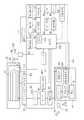
次に、図6を参照して、上述した輸液ポンプ10の電気的な構成を説明する。図6は、輸液ポンプ10の電気的な構成を示すブロック図である。
図6に示すブロック図では、本体11の前筐体49と後筐体44と、カバー12を示しており、カバー12側にはカセット20とこのカセット20のチューブ21が配置されている。
図6に示す後筐体44には、ジャック78と、電源回路80と、繰り返して充電可能な電池Bと、充電回路200と、電池残量回路201が配置されている。ジャック78は、電池Bと電源回路80と充電回路200に対して電気的に接続されている。充電回路200は電池Bの電気的に接続されている。電池残量回路201は、充電回路200と電源回路80と電池Bに対して電気的に接続されている。充電回路200は制御部100に電気的に接続されている。電池残量回路201は、電池Bの電池残量を測定して、制御部100に通知する。
この電池Bは、制御部100の指令により、ジャック78に接続された電源アダプタ70と電源回路80を通じて、充電回路200から充電できるようになっている。すなわち、輸液ポンプ10が電源アダプタ70を介して図4に示す商用交流電源のコンセント46に接続されていれば、100Vの商用交流電源を電源アダプタ70により直流電源に変換して、制御部100が電池残量回路201からの電池残量に基づいて指令することにより、電源回路80と充電回路200を通じて電池Bに対して充電できるようになっている。Next, the electrical configuration of the
In the block diagram shown in FIG. 6, the
A
The battery B can be charged from the charging
図6に示すように、前筐体49には、ロータユニット31と、空液検出部82と、閉塞検出部83を備えている。ロータユニット31は、ギア31Gを介してモータMに連結されており、モータMはモータ駆動回路81からの駆動信号により、ロータユニット31を連続回転させることができる。回転検出回路81Tは、モータMの回転状態を検出して制御部100にモータの回転状態信号を送る。電源回路80は、モータ駆動区回路18と制御部100に電気的に接続されており、モータ駆動区回路18と制御部100に対して電源供給を行う。 As shown in FIG. 6, the
図6の空液検出部82と閉塞検出部83は制御部100に電気的に接続され、空液検出部82は、チューブ21内が薬液により満たされているか気泡が存在するかを検出して、制御部100に通知する。閉塞検出部83は、チューブ21が閉塞されてチューブ21の直径が大きくなったことを検出して薬液が通過していないことを制御部100に通知する。
図6には突起部材99とスイッチ134が配置されている。図2と図6に示すように突起部材99とスイッチ134は電源オンオフ操作部150を構成しており、すでに図2を参照して説明しているが、カセット20がカセット収納部15内に収納された状態では、突起部材99は、図2に示す付勢部材133の力に抗してZ1方向に押されることで、図6に示すスイッチ134がオンとなり、このオン信号は制御部100に供給されるようになっている。逆に、カセット20がカセット収納部15内から外されると、突起部材99は、図2に示す付勢部材133の力によりZ2方向に押されることで、図に示すスイッチ134がオフとなり、このオフ信号は制御部100に供給されるようになっている。The air-
In FIG. 6, a protruding
この電源オンオフ操作部150は、カセット20がカセット収納部15に対して正常に装着されているかを検出する検出センサを兼ねている。これにより、電源オンオフ操作部150は、オンオフ信号を発生して制御部100に供給するだけではなく、オン信号を制御部100に供給することで、制御部100は、カセット20がカセット収納部15に対して正常に装着されていると判断するようになっている。
開始停止スイッチ17は、開始停止検出回路84に電気的に接続され、開始停止検出回路84は、開始停止スイッチ17が、図1に示す開始位置に位置されているか停止位置に位置されているかを検出して、その状態を制御部100に通知する。制御部100はCPU110を有しており、メモリ部111は、制御部100のCPU111により処理すべきプログラムが記憶されているROM(読み出し専用メモリ)である。The power on / off
The start /
図6の表示部18は、制御回路18Tに電気的に接続され、点灯表示部LPは、制御回路85に電気的に接続されている。各制御回路18Tと制御回路85は制御部100に電気的に接続され、制御部100の指令により、制御回路18Tは表示部18に必要な内容を表示させる。また、制御部100の指令により、制御回路85は点灯表示部18を例えば点滅させて、患者に点滅により警報があることを報知することができる。
ブザー88は、ブザー回路90に電気的に接続され、スピーカ89は、音声回路91に電気的に接続されている。ブザー回路90と音声回路91は、制御部100に電気的に接続されている。その他に、外部通信回路101が制御部100に電気的に接続されている。The
The
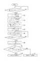
次に、図7を参照して、上述した輸液ポンプ10の動作について説明する。図7は、輸液ポンプ10の動作例を示すフロー図である。
患者が輸液ポンプ10を最初に使用しようとする場合には、図7のステップS1から作業を開始する。図5に示すように、例えば患者が2本の充電可能な電池Bを電池収容部41内に収容して、ステップS2では、図2に示すようにカバー12を開けてカセット収納部15を開放し、図3に示すようにカセット20をこのカセット収納部15内に装着する。
ただし、患者が最初に輸液ポンプ10を使用する場合には、ステップS1から始めるが、2回目からの輸液ポンプ10の使用に際しては、電池Bは電池収容部41に入れたままで、ステップS2に示すカセット20の装着動作から始めればよい。Next, the operation of the
When the patient intends to use the
However, when the patient uses the
図7のステップS3では、図3と図6に示すように、突起部材99がカセット20の装着によりZ1方向に押されるのでスイッチ134がオンする。このため、スイッチ134のオン信号が制御部100に自動的に供給される。これにより、制御部100は、自動的に主電源をオンするために電源回路80を動作させることができ、患者が電源の投入を忘れてしまうといったトラブルを防止できる。
図7のステップS4では、患者が図3に示す開始停止スイッチ17をスライドして「停止位置」から「開始位置」にした後に、図7のステップS5では、図6の電源回路80がモータ駆動回路81に指令を与えてモータMを駆動することで、図3に示すロータユニット31が矢印方向に沿って連続回転する。これにより、図2の矢印方向に沿ってロータユニット31の複数のチューブ押圧部31Rが回転することにより順次チューブ21を順次押圧して、チューブ21に対して蠕動様運動を付与するIn step S3 of FIG. 7, as shown in FIGS. 3 and 6, the
In step S4 of FIG. 7, after the patient slides the start /
ステップS6では、チューブ21の閉塞を解除して、チューブ21による薬液の送液を開始する。ステップS7において、チューブ21による薬液の送液作業が終了したら、ステップS8では、患者は図3に示すようにカバー12を開けてカセット収納部15を開放して、カセット20をカセット収納部15から取り外す。 In step S6, the blockage of the
図7のステップS9では、カセット20が取り外されたことで、図6の突起部材99がZ2方向に移動するのでスイッチ134は自動的にスイッチオフになり、オフ信号が制御部100に供給される。制御部100は、オフ信号が与えられてから、予め定めた待機時間、例えば数分から10分間経過するのを待つ。そして、ステップS10において、制御部100はこのあらかじめ定めた待機時間が経過すると、電源回路80を自動的に電源オフする。これにより、患者が電源オフをすることを忘れてしまうといったトラブルを防ぐことができる。 In step S9 of FIG. 7, since the protruding
しかし、ステップS11において、制御部100が、カセット20が取り外されてからあらかじめ定めた待機時間が経過するまで自動的に電源オフするのを待つ、言い換えれば電源オンを継続するのは、次の理由からである。すなわち、例えばカセット20を装着する際にチューブ21が絡んだり捩じったりしてしまい、患者がカセット20を一旦カセット収納部15から取り外してカセット20を再度カセット収納部15に装着し直す等の作業を行う場合には、カセット20が取り外されからすぐに電源がオフされてしまうと、再度カセット20を装着し直した後に上述した処理シーケンスを最初からやり直す必要が出てくる。このシーケンスをやり直すことは、患者にとって再度の作業の繰り返しが負担になるので好ましくはない。 However, in step S11, the
以上説明したように、本発明の実施形態の輸液ポンプ10では、図4に示すように本体11と商用交流電源のコンセント46とを、電源アダプタ(ACアダプ)70を介して電気的に接続することで、図6に示す本体11の内部に収容されている充電可能な電池Bは、電源回路80と充電回路200を通じて自動的に充電することができる。これにより、電池を輸液ポンプ内に入れたままで出さないで電池に自動的に充電することができ、患者あるいは周囲の家族の人による毎日の電池の交換作業が不要になり、輸液ポンプ10の使用勝手が向上する。 As described above, in the
患者あるいは周囲の家族の人が、カセット20をカセット収納部15に正しく装着することで、カセット検出センサとしての図6に示す突起部材99がZ1方向に移動してスイッチ134をオンして、このオン信号が制御部100に供給できる。従って、突起部材99とスイッチ134は、カセット20がカセット収納部15内に正常にセットされていることを検出するとともに、主電源をオンしてモータMを作動させて、チューブ21による送液動作を自動的に開始することができる。このため、カセット20がカセット収納部15内に装着されたと同時に電源をオンできるので、患者あるいは周囲の家族の人が電源を投入することを忘れてしまうことを防ぐことができる。 When the patient or a person in the surrounding family correctly attaches the
しかも、すでに説明したように、電源オンオフ操作部150は、カセット20がカセット収納部15に対して正常に装着されているかを検出する検出センサを兼ねているので、電源オンオフ操作部150は、オンオフ信号を発生して制御部100に供給するだけではない。すなわち、電源オンオフ操作部150は、カセット20がカセット収納部15に対して正常に装着されている場合には、オン信号を制御部100に供給することで、制御部100は、カセット20がカセット収納部15に対して正常に装着されていると、同時に判断することできる。しかも、好ましくは電源オンオフ操作部150が、閉塞検出部83と一体化して構成することにより、チューブ21の閉塞検出も兼ねることができ、電源オンオフ操作部150と閉塞検出部83を別々に配置する必要がないので、輸液ポンプ10の小型化が図れる。
また、送液動作が終了して、例えば患者がカバー12を開けてカセット20をカセット収納部15から取り外して、予め定めた待機時間を経過した時点で、自動的に電源オフすることができる。これにより、電池を輸液ポンプ内に入れたままで出さないで電池に自動的に充電することができ、電池の交換作業を不要にできる。In addition, as described above, the power on / off
In addition, when the liquid feeding operation is completed, for example, the patient opens the
本発明の実施形態の輸液ポンプ10は、外部から薬液を導入するための輸液チューブ21を有するカセット20を着脱可能に装着した状態で、輸液チューブ21に対して圧接し、該輸液チューブ21に対して蠕動様運動をさせて、薬液を送出するための輸液送り部としてのロータユニット31と、このロータユニット31を駆動するための電源として繰り返して充電可能な電池Bと、ロータユニット31を駆動するための電源として商用交流電源に接続して交流/直流変換し、電池に充電可能な電源アダプタ70と、制御部100と、カセット20を装着するとロータユニット31へ供給する電源をオンするためのオン信号を制御部100に送り、カセット20を外すとロータユニット31へ供給する電源をオフするためのオフ信号を制御部100に送る電源オンオフ操作部150とを有することを特徴とする。
これにより、繰り返して充電可能な電池を輸液ポンプに装填したままで、この電池に対して自動的に充電することができるので、例えば患者や周囲の家族の人が電池の交換作業をする必要がなくなり、輸液ポンプの使用勝手が向上する。The infusion pump 10 according to the embodiment of the present invention is in pressure contact with the
As a result, a rechargeable battery can be charged automatically with the rechargeable battery loaded in the infusion pump. For example, a patient or a family member needs to replace the battery. Ease of use of the infusion pump is improved.
電源オンオフ操作部150は、カセット20を装着することで移動しカセット20を外すと逆に移動する突起部材と、カセット20を装着して突起部材99を移動することによりオン信号を制御部100に送り、カセット20を外して突起部材99を逆に移動することによりオフ信号を制御部100に送るスイッチ134とを有する。
これにより、突起部材99を移動するだけでスイッチ134を操作でき、簡単な構成でありながら制御部199に対して電源のオン信号とオフ信号を供給できる。The power on / off
As a result, the
制御部100は、カセット20を外してオフ信号が送られてから予め定めた待機時間を経過すると、電源を自動的にオフにする。
これにより、例えば輸液チューブ21がからんだり捩じったりしてカセット20を一旦外して再度装着しようとする場合に、電源をオンしたまま維持できるので電源がオフしてしまうのを防ぎ、再度最初からシーケンスを繰り返す必要が無いので、輸液ポンプ10の使用勝手が向上する。The
As a result, for example, when the
カセット20を着脱可能に収納するカセット収納部15を有し、電源オンオフ操作部150は、カセット20がカセット収納部15に対して正常に装着されているかを検出する検出センサを兼ねていることを特徴とする。
これにより、電源オンオフ操作部150は、カセット20がカセット収納部15に対して正常に装着されているかを検出できる。The
As a result, the power on / off
ところで、本発明は上記実施形態に限定されない。
点灯表示部LPは、発光ダイオードランプを用いているが、ほかの種類のランプでもよい。電池収容部41は、本体11の裏面に露出せず本体11の側面に露出してもよく、その場合、蓋体の形状は本実施形態とは異なる形態とすることができるが、本実施形態と同様に係合構造を採用することができる。輸液ポンプのカバーの構成やカセットの着脱構造は、上記実施形態の構成に限定されず、種々の形態が採用され得る。例えば、カセット20に設けたストッパ26は、これを本体11側に設けて、外部に露出させ、カセットを装着した際に、カセット内に入り込んで、チューブを押圧する構成にする等種々の改変が可能である。
また、スライド(摺動)部材側に係合段部や傾斜面を設け、本体側に係合片や解除付勢部を設けて、上述の実施形態と同等の作用を発揮させるようにしてもよい。By the way, the present invention is not limited to the above embodiment.
The light emitting display portion LP uses a light emitting diode lamp, but may be another type of lamp. The
In addition, an engagement step portion and an inclined surface are provided on the slide (sliding) member side, and an engagement piece and a release urging portion are provided on the main body side so that the same effect as the above-described embodiment can be exhibited. Good.
10・・・輸液ポンプ、11・・・本体、12・・・カバー、15・・・カセット収納部、18・・・表示部(報知手段)、20・・・カセット、21・・・(輸液)チューブ、31・・・ロータユニット(輸液送り部の一例)、41・・・電池収容部、88・・・ブザー(報知手段)、89・・・スピーカ(報知手段)、99・・・突起部材、134・・・スイッチ、150・・・電源オンオフ操作部、B・・・繰り返して充電可能な電池 DESCRIPTION OF
Claims (4)
Translated fromJapanese該輸液送り部を駆動するための電源として繰り返して充電可能な電池と、
前記輸液送り部を駆動するための電源として商用交流電源に接続して交流/直流変換し、前記電池に充電可能な電源アダプタと、
前記輸液送り部を駆動するとともに、前記電源と接続された制御部と、
前記カセットを装着すると前記輸液送り部へ供給する前記電源をオンするためのオン信号を前記制御部に送り、前記カセットを外すと前記輸液送り部へ供給する前記電源をオフするためのオフ信号を前記制御部に送る電源オンオフ操作部と
を有することを特徴とする輸液ポンプ。An infusion feed section for delivering a chemical solution, which is used in a state in which a cassette having an infusion tube is detachably mounted;
A battery that can be repeatedly charged as a power source for driving the infusion feeding section;
A power supply adapter that is connected to a commercial AC power source as a power source for driving the infusion feeding unit, is AC / DC converted, and can be charged to the battery,
While driving the infusion feeding unit, a control unit connected to the power source,
When the cassette is attached, an on signal for turning on the power supplied to the infusion feeding section is sent to the control section, and when the cassette is removed, an off signal for turning off the power supplied to the infusion feeding section is sent. An infusion pump, comprising: a power on / off operation unit that is sent to the control unit.
It has a cassette storage part for detachably storing the cassette, and the power on / off operation part also serves as a detection sensor for detecting whether the cassette is normally attached to the cassette storage part. The infusion pump according to any one of claims 1 to 3.
Priority Applications (1)
| Application Number | Priority Date | Filing Date | Title |
|---|---|---|---|
| JP2010066891AJP2011194155A (en) | 2010-03-23 | 2010-03-23 | Infusion pump |
Applications Claiming Priority (1)
| Application Number | Priority Date | Filing Date | Title |
|---|---|---|---|
| JP2010066891AJP2011194155A (en) | 2010-03-23 | 2010-03-23 | Infusion pump |
Publications (1)
| Publication Number | Publication Date |
|---|---|
| JP2011194155Atrue JP2011194155A (en) | 2011-10-06 |
Family
ID=44873079
Family Applications (1)
| Application Number | Title | Priority Date | Filing Date |
|---|---|---|---|
| JP2010066891ACeasedJP2011194155A (en) | 2010-03-23 | 2010-03-23 | Infusion pump |
Country Status (1)
| Country | Link |
|---|---|
| JP (1) | JP2011194155A (en) |
Cited By (3)
| Publication number | Priority date | Publication date | Assignee | Title |
|---|---|---|---|---|
| EP2902047A4 (en)* | 2012-09-27 | 2016-05-18 | Terumo Corp | Infusion pump |
| JP2016526252A (en)* | 2013-04-29 | 2016-09-01 | スミスズ メディカル エーエスディー,インコーポレイティド | Rotary electrical connector |
| AU2019202164B2 (en)* | 2012-12-21 | 2021-08-26 | Deka Products Limited Partnership | Syringe pump system |
Citations (3)
| Publication number | Priority date | Publication date | Assignee | Title |
|---|---|---|---|---|
| JPH08164203A (en)* | 1994-12-12 | 1996-06-25 | Medeiko Media:Kk | Drip infusion liquid measuring device |
| JP2001025505A (en)* | 1999-07-14 | 2001-01-30 | Terumo Corp | Transfusion pump |
| WO2009113060A2 (en)* | 2008-03-10 | 2009-09-17 | Medingo Ltd. | Infusion and sensing device with battery charging and data transferring mechanisms |
- 2010
- 2010-03-23JPJP2010066891Apatent/JP2011194155A/ennot_activeCeased
Patent Citations (4)
| Publication number | Priority date | Publication date | Assignee | Title |
|---|---|---|---|---|
| JPH08164203A (en)* | 1994-12-12 | 1996-06-25 | Medeiko Media:Kk | Drip infusion liquid measuring device |
| JP2001025505A (en)* | 1999-07-14 | 2001-01-30 | Terumo Corp | Transfusion pump |
| WO2009113060A2 (en)* | 2008-03-10 | 2009-09-17 | Medingo Ltd. | Infusion and sensing device with battery charging and data transferring mechanisms |
| JP2011517581A (en)* | 2008-03-10 | 2011-06-16 | メディンゴ・リミテッド | Injection and sensor device with battery charging mechanism and data transfer mechanism |
Cited By (6)
| Publication number | Priority date | Publication date | Assignee | Title |
|---|---|---|---|---|
| EP2902047A4 (en)* | 2012-09-27 | 2016-05-18 | Terumo Corp | Infusion pump |
| US10549033B2 (en) | 2012-09-27 | 2020-02-04 | Terumo Kabushiki Kaisha | Infusion pump |
| AU2019202164B2 (en)* | 2012-12-21 | 2021-08-26 | Deka Products Limited Partnership | Syringe pump system |
| JP2016526252A (en)* | 2013-04-29 | 2016-09-01 | スミスズ メディカル エーエスディー,インコーポレイティド | Rotary electrical connector |
| EP2992574A4 (en)* | 2013-04-29 | 2017-01-04 | Smiths Medical ASD, Inc. | Rotatable electrical connectors |
| US10016556B2 (en) | 2013-04-29 | 2018-07-10 | Smiths Medical Asd, Inc. | Rotatable electrical connectors |
Similar Documents
| Publication | Publication Date | Title |
|---|---|---|
| JP5598903B2 (en) | Electric syringe for chemicals | |
| JP4261910B2 (en) | Syringe pump | |
| CA2991138A1 (en) | Aerosol delivery systems and related methods | |
| JP3193281B2 (en) | Syringe pump | |
| JP2011194155A (en) | Infusion pump | |
| JP4034491B2 (en) | Syringe pump and drive control method when occlusion is detected | |
| JPWO2018101113A1 (en) | Dispenser | |
| WO2013046610A1 (en) | Support member attachment unit and medical pump provided with said attachment unit | |
| JP6240239B2 (en) | Portable infusion pump | |
| JP4754078B2 (en) | Syringe pump and liquid feeding method | |
| WO2012120764A1 (en) | Medical pump | |
| JP2012205866A (en) | Infusion pump | |
| JP2004024884A (en) | Syringe pump | |
| JP2000350782A (en) | Syringe pump and injecting method | |
| JP2012205739A (en) | Infusion pump | |
| JP2012205737A (en) | Transfusion management system | |
| JP2011200326A (en) | Infusion pump | |
| JP5651356B2 (en) | Home infusion pump | |
| JP5897809B2 (en) | Portable infusion pump | |
| JP2012187129A (en) | Infusion pump | |
| JP2013132377A (en) | Syringe pump | |
| CN215959570U (en) | Flip type toilet lid with automatic cover changing function | |
| JP3343182B2 (en) | Syringe pump | |
| JP2012200543A (en) | Infusion pump | |
| JP3581695B2 (en) | Syringe pump |
Legal Events
| Date | Code | Title | Description |
|---|---|---|---|
| A621 | Written request for application examination | Free format text:JAPANESE INTERMEDIATE CODE: A621 Effective date:20130308 | |
| A977 | Report on retrieval | Free format text:JAPANESE INTERMEDIATE CODE: A971007 Effective date:20140109 | |
| A131 | Notification of reasons for refusal | Free format text:JAPANESE INTERMEDIATE CODE: A131 Effective date:20140116 | |
| A521 | Written amendment | Free format text:JAPANESE INTERMEDIATE CODE: A523 Effective date:20140310 | |
| A01 | Written decision to grant a patent or to grant a registration (utility model) | Free format text:JAPANESE INTERMEDIATE CODE: A01 Effective date:20140604 | |
| A045 | Written measure of dismissal of application | Free format text:JAPANESE INTERMEDIATE CODE: A045 Effective date:20141029 |