JP2011193671A - vehicle - Google Patents
vehicleDownload PDFInfo
- Publication number
- JP2011193671A JP2011193671AJP2010058793AJP2010058793AJP2011193671AJP 2011193671 AJP2011193671 AJP 2011193671AJP 2010058793 AJP2010058793 AJP 2010058793AJP 2010058793 AJP2010058793 AJP 2010058793AJP 2011193671 AJP2011193671 AJP 2011193671A
- Authority
- JP
- Japan
- Prior art keywords
- power
- vehicle
- unit
- power transmission
- coil
- Prior art date
- Legal status (The legal status is an assumption and is not a legal conclusion. Google has not performed a legal analysis and makes no representation as to the accuracy of the status listed.)
- Granted
Links
Images


Classifications
- B—PERFORMING OPERATIONS; TRANSPORTING
- B60—VEHICLES IN GENERAL
- B60L—PROPULSION OF ELECTRICALLY-PROPELLED VEHICLES; SUPPLYING ELECTRIC POWER FOR AUXILIARY EQUIPMENT OF ELECTRICALLY-PROPELLED VEHICLES; ELECTRODYNAMIC BRAKE SYSTEMS FOR VEHICLES IN GENERAL; MAGNETIC SUSPENSION OR LEVITATION FOR VEHICLES; MONITORING OPERATING VARIABLES OF ELECTRICALLY-PROPELLED VEHICLES; ELECTRIC SAFETY DEVICES FOR ELECTRICALLY-PROPELLED VEHICLES
- B60L50/00—Electric propulsion with power supplied within the vehicle
- B60L50/10—Electric propulsion with power supplied within the vehicle using propulsion power supplied by engine-driven generators, e.g. generators driven by combustion engines
- B60L50/16—Electric propulsion with power supplied within the vehicle using propulsion power supplied by engine-driven generators, e.g. generators driven by combustion engines with provision for separate direct mechanical propulsion
- B—PERFORMING OPERATIONS; TRANSPORTING
- B60—VEHICLES IN GENERAL
- B60L—PROPULSION OF ELECTRICALLY-PROPELLED VEHICLES; SUPPLYING ELECTRIC POWER FOR AUXILIARY EQUIPMENT OF ELECTRICALLY-PROPELLED VEHICLES; ELECTRODYNAMIC BRAKE SYSTEMS FOR VEHICLES IN GENERAL; MAGNETIC SUSPENSION OR LEVITATION FOR VEHICLES; MONITORING OPERATING VARIABLES OF ELECTRICALLY-PROPELLED VEHICLES; ELECTRIC SAFETY DEVICES FOR ELECTRICALLY-PROPELLED VEHICLES
- B60L50/00—Electric propulsion with power supplied within the vehicle
- B60L50/50—Electric propulsion with power supplied within the vehicle using propulsion power supplied by batteries or fuel cells
- B60L50/60—Electric propulsion with power supplied within the vehicle using propulsion power supplied by batteries or fuel cells using power supplied by batteries
- B60L50/61—Electric propulsion with power supplied within the vehicle using propulsion power supplied by batteries or fuel cells using power supplied by batteries by batteries charged by engine-driven generators, e.g. series hybrid electric vehicles
- B—PERFORMING OPERATIONS; TRANSPORTING
- B60—VEHICLES IN GENERAL
- B60L—PROPULSION OF ELECTRICALLY-PROPELLED VEHICLES; SUPPLYING ELECTRIC POWER FOR AUXILIARY EQUIPMENT OF ELECTRICALLY-PROPELLED VEHICLES; ELECTRODYNAMIC BRAKE SYSTEMS FOR VEHICLES IN GENERAL; MAGNETIC SUSPENSION OR LEVITATION FOR VEHICLES; MONITORING OPERATING VARIABLES OF ELECTRICALLY-PROPELLED VEHICLES; ELECTRIC SAFETY DEVICES FOR ELECTRICALLY-PROPELLED VEHICLES
- B60L53/00—Methods of charging batteries, specially adapted for electric vehicles; Charging stations or on-board charging equipment therefor; Exchange of energy storage elements in electric vehicles
- B60L53/10—Methods of charging batteries, specially adapted for electric vehicles; Charging stations or on-board charging equipment therefor; Exchange of energy storage elements in electric vehicles characterised by the energy transfer between the charging station and the vehicle
- B60L53/12—Inductive energy transfer
- B60L53/126—Methods for pairing a vehicle and a charging station, e.g. establishing a one-to-one relation between a wireless power transmitter and a wireless power receiver
- B—PERFORMING OPERATIONS; TRANSPORTING
- B60—VEHICLES IN GENERAL
- B60L—PROPULSION OF ELECTRICALLY-PROPELLED VEHICLES; SUPPLYING ELECTRIC POWER FOR AUXILIARY EQUIPMENT OF ELECTRICALLY-PROPELLED VEHICLES; ELECTRODYNAMIC BRAKE SYSTEMS FOR VEHICLES IN GENERAL; MAGNETIC SUSPENSION OR LEVITATION FOR VEHICLES; MONITORING OPERATING VARIABLES OF ELECTRICALLY-PROPELLED VEHICLES; ELECTRIC SAFETY DEVICES FOR ELECTRICALLY-PROPELLED VEHICLES
- B60L53/00—Methods of charging batteries, specially adapted for electric vehicles; Charging stations or on-board charging equipment therefor; Exchange of energy storage elements in electric vehicles
- B60L53/30—Constructional details of charging stations
- B60L53/35—Means for automatic or assisted adjustment of the relative position of charging devices and vehicles
- B60L53/36—Means for automatic or assisted adjustment of the relative position of charging devices and vehicles by positioning the vehicle
- B—PERFORMING OPERATIONS; TRANSPORTING
- B60—VEHICLES IN GENERAL
- B60L—PROPULSION OF ELECTRICALLY-PROPELLED VEHICLES; SUPPLYING ELECTRIC POWER FOR AUXILIARY EQUIPMENT OF ELECTRICALLY-PROPELLED VEHICLES; ELECTRODYNAMIC BRAKE SYSTEMS FOR VEHICLES IN GENERAL; MAGNETIC SUSPENSION OR LEVITATION FOR VEHICLES; MONITORING OPERATING VARIABLES OF ELECTRICALLY-PROPELLED VEHICLES; ELECTRIC SAFETY DEVICES FOR ELECTRICALLY-PROPELLED VEHICLES
- B60L53/00—Methods of charging batteries, specially adapted for electric vehicles; Charging stations or on-board charging equipment therefor; Exchange of energy storage elements in electric vehicles
- B60L53/30—Constructional details of charging stations
- B60L53/35—Means for automatic or assisted adjustment of the relative position of charging devices and vehicles
- B60L53/37—Means for automatic or assisted adjustment of the relative position of charging devices and vehicles using optical position determination, e.g. using cameras
- B—PERFORMING OPERATIONS; TRANSPORTING
- B60—VEHICLES IN GENERAL
- B60L—PROPULSION OF ELECTRICALLY-PROPELLED VEHICLES; SUPPLYING ELECTRIC POWER FOR AUXILIARY EQUIPMENT OF ELECTRICALLY-PROPELLED VEHICLES; ELECTRODYNAMIC BRAKE SYSTEMS FOR VEHICLES IN GENERAL; MAGNETIC SUSPENSION OR LEVITATION FOR VEHICLES; MONITORING OPERATING VARIABLES OF ELECTRICALLY-PROPELLED VEHICLES; ELECTRIC SAFETY DEVICES FOR ELECTRICALLY-PROPELLED VEHICLES
- B60L53/00—Methods of charging batteries, specially adapted for electric vehicles; Charging stations or on-board charging equipment therefor; Exchange of energy storage elements in electric vehicles
- B60L53/30—Constructional details of charging stations
- B60L53/35—Means for automatic or assisted adjustment of the relative position of charging devices and vehicles
- B60L53/38—Means for automatic or assisted adjustment of the relative position of charging devices and vehicles specially adapted for charging by inductive energy transfer
- B60L53/39—Means for automatic or assisted adjustment of the relative position of charging devices and vehicles specially adapted for charging by inductive energy transfer with position-responsive activation of primary coils
- B—PERFORMING OPERATIONS; TRANSPORTING
- B60—VEHICLES IN GENERAL
- B60L—PROPULSION OF ELECTRICALLY-PROPELLED VEHICLES; SUPPLYING ELECTRIC POWER FOR AUXILIARY EQUIPMENT OF ELECTRICALLY-PROPELLED VEHICLES; ELECTRODYNAMIC BRAKE SYSTEMS FOR VEHICLES IN GENERAL; MAGNETIC SUSPENSION OR LEVITATION FOR VEHICLES; MONITORING OPERATING VARIABLES OF ELECTRICALLY-PROPELLED VEHICLES; ELECTRIC SAFETY DEVICES FOR ELECTRICALLY-PROPELLED VEHICLES
- B60L2210/00—Converter types
- B60L2210/10—DC to DC converters
- B60L2210/14—Boost converters
- B—PERFORMING OPERATIONS; TRANSPORTING
- B60—VEHICLES IN GENERAL
- B60L—PROPULSION OF ELECTRICALLY-PROPELLED VEHICLES; SUPPLYING ELECTRIC POWER FOR AUXILIARY EQUIPMENT OF ELECTRICALLY-PROPELLED VEHICLES; ELECTRODYNAMIC BRAKE SYSTEMS FOR VEHICLES IN GENERAL; MAGNETIC SUSPENSION OR LEVITATION FOR VEHICLES; MONITORING OPERATING VARIABLES OF ELECTRICALLY-PROPELLED VEHICLES; ELECTRIC SAFETY DEVICES FOR ELECTRICALLY-PROPELLED VEHICLES
- B60L2210/00—Converter types
- B60L2210/40—DC to AC converters
- B—PERFORMING OPERATIONS; TRANSPORTING
- B60—VEHICLES IN GENERAL
- B60L—PROPULSION OF ELECTRICALLY-PROPELLED VEHICLES; SUPPLYING ELECTRIC POWER FOR AUXILIARY EQUIPMENT OF ELECTRICALLY-PROPELLED VEHICLES; ELECTRODYNAMIC BRAKE SYSTEMS FOR VEHICLES IN GENERAL; MAGNETIC SUSPENSION OR LEVITATION FOR VEHICLES; MONITORING OPERATING VARIABLES OF ELECTRICALLY-PROPELLED VEHICLES; ELECTRIC SAFETY DEVICES FOR ELECTRICALLY-PROPELLED VEHICLES
- B60L2220/00—Electrical machine types; Structures or applications thereof
- B60L2220/10—Electrical machine types
- B60L2220/14—Synchronous machines
- Y—GENERAL TAGGING OF NEW TECHNOLOGICAL DEVELOPMENTS; GENERAL TAGGING OF CROSS-SECTIONAL TECHNOLOGIES SPANNING OVER SEVERAL SECTIONS OF THE IPC; TECHNICAL SUBJECTS COVERED BY FORMER USPC CROSS-REFERENCE ART COLLECTIONS [XRACs] AND DIGESTS
- Y02—TECHNOLOGIES OR APPLICATIONS FOR MITIGATION OR ADAPTATION AGAINST CLIMATE CHANGE
- Y02T—CLIMATE CHANGE MITIGATION TECHNOLOGIES RELATED TO TRANSPORTATION
- Y02T10/00—Road transport of goods or passengers
- Y02T10/60—Other road transportation technologies with climate change mitigation effect
- Y02T10/62—Hybrid vehicles
- Y—GENERAL TAGGING OF NEW TECHNOLOGICAL DEVELOPMENTS; GENERAL TAGGING OF CROSS-SECTIONAL TECHNOLOGIES SPANNING OVER SEVERAL SECTIONS OF THE IPC; TECHNICAL SUBJECTS COVERED BY FORMER USPC CROSS-REFERENCE ART COLLECTIONS [XRACs] AND DIGESTS
- Y02—TECHNOLOGIES OR APPLICATIONS FOR MITIGATION OR ADAPTATION AGAINST CLIMATE CHANGE
- Y02T—CLIMATE CHANGE MITIGATION TECHNOLOGIES RELATED TO TRANSPORTATION
- Y02T10/00—Road transport of goods or passengers
- Y02T10/60—Other road transportation technologies with climate change mitigation effect
- Y02T10/70—Energy storage systems for electromobility, e.g. batteries
- Y—GENERAL TAGGING OF NEW TECHNOLOGICAL DEVELOPMENTS; GENERAL TAGGING OF CROSS-SECTIONAL TECHNOLOGIES SPANNING OVER SEVERAL SECTIONS OF THE IPC; TECHNICAL SUBJECTS COVERED BY FORMER USPC CROSS-REFERENCE ART COLLECTIONS [XRACs] AND DIGESTS
- Y02—TECHNOLOGIES OR APPLICATIONS FOR MITIGATION OR ADAPTATION AGAINST CLIMATE CHANGE
- Y02T—CLIMATE CHANGE MITIGATION TECHNOLOGIES RELATED TO TRANSPORTATION
- Y02T10/00—Road transport of goods or passengers
- Y02T10/60—Other road transportation technologies with climate change mitigation effect
- Y02T10/7072—Electromobility specific charging systems or methods for batteries, ultracapacitors, supercapacitors or double-layer capacitors
- Y—GENERAL TAGGING OF NEW TECHNOLOGICAL DEVELOPMENTS; GENERAL TAGGING OF CROSS-SECTIONAL TECHNOLOGIES SPANNING OVER SEVERAL SECTIONS OF THE IPC; TECHNICAL SUBJECTS COVERED BY FORMER USPC CROSS-REFERENCE ART COLLECTIONS [XRACs] AND DIGESTS
- Y02—TECHNOLOGIES OR APPLICATIONS FOR MITIGATION OR ADAPTATION AGAINST CLIMATE CHANGE
- Y02T—CLIMATE CHANGE MITIGATION TECHNOLOGIES RELATED TO TRANSPORTATION
- Y02T10/00—Road transport of goods or passengers
- Y02T10/60—Other road transportation technologies with climate change mitigation effect
- Y02T10/72—Electric energy management in electromobility
- Y—GENERAL TAGGING OF NEW TECHNOLOGICAL DEVELOPMENTS; GENERAL TAGGING OF CROSS-SECTIONAL TECHNOLOGIES SPANNING OVER SEVERAL SECTIONS OF THE IPC; TECHNICAL SUBJECTS COVERED BY FORMER USPC CROSS-REFERENCE ART COLLECTIONS [XRACs] AND DIGESTS
- Y02—TECHNOLOGIES OR APPLICATIONS FOR MITIGATION OR ADAPTATION AGAINST CLIMATE CHANGE
- Y02T—CLIMATE CHANGE MITIGATION TECHNOLOGIES RELATED TO TRANSPORTATION
- Y02T90/00—Enabling technologies or technologies with a potential or indirect contribution to GHG emissions mitigation
- Y02T90/10—Technologies relating to charging of electric vehicles
- Y02T90/12—Electric charging stations
- Y—GENERAL TAGGING OF NEW TECHNOLOGICAL DEVELOPMENTS; GENERAL TAGGING OF CROSS-SECTIONAL TECHNOLOGIES SPANNING OVER SEVERAL SECTIONS OF THE IPC; TECHNICAL SUBJECTS COVERED BY FORMER USPC CROSS-REFERENCE ART COLLECTIONS [XRACs] AND DIGESTS
- Y02—TECHNOLOGIES OR APPLICATIONS FOR MITIGATION OR ADAPTATION AGAINST CLIMATE CHANGE
- Y02T—CLIMATE CHANGE MITIGATION TECHNOLOGIES RELATED TO TRANSPORTATION
- Y02T90/00—Enabling technologies or technologies with a potential or indirect contribution to GHG emissions mitigation
- Y02T90/10—Technologies relating to charging of electric vehicles
- Y02T90/14—Plug-in electric vehicles
Landscapes
- Engineering & Computer Science (AREA)
- Mechanical Engineering (AREA)
- Power Engineering (AREA)
- Transportation (AREA)
- Sustainable Development (AREA)
- Life Sciences & Earth Sciences (AREA)
- Computer Networks & Wireless Communication (AREA)
- Sustainable Energy (AREA)
- Current-Collector Devices For Electrically Propelled Vehicles (AREA)
- Electric Propulsion And Braking For Vehicles (AREA)
- Charge And Discharge Circuits For Batteries Or The Like (AREA)
- Arrangement Or Mounting Of Propulsion Units For Vehicles (AREA)
- Hybrid Electric Vehicles (AREA)
- Cooling, Air Intake And Gas Exhaust, And Fuel Tank Arrangements In Propulsion Units (AREA)
Abstract
Description
Translated fromJapanese本発明は、車両に関し、特に、非接触で車両外部に設けられた送電コイルから受電可能な車両に関する。 The present invention relates to a vehicle, and more particularly to a vehicle that can receive power from a power transmission coil provided outside the vehicle in a non-contact manner.
従来からワイヤレスで、車両に搭載されたバッテリを充電する充電システム等について各種提案されている。 Conventionally, various charging systems for charging a battery mounted in a vehicle wirelessly have been proposed.
特開2004−229425号公報には、マイクロ波等の無線波を利用して、車両に搭載されたバッテリを充電する車両駐車システムが記載されている。 Japanese Patent Application Laid-Open No. 2004-229425 describes a vehicle parking system that charges a battery mounted on a vehicle using radio waves such as microwaves.
この車両駐車システムにおいては、車両の駐車中、駐車場やエネルギーステーションなどに設置されたエネルギー供給設備が車両にマイクロ波を送信する。マイクロ波発生器は、車両が走行中に供給されるマイクロ波よりも高い強度のマイクロ波を発生する。車両は、マイクロ波を受信して電気エネルギーに変換し、バッテリを充電する。 In this vehicle parking system, an energy supply facility installed in a parking lot or an energy station transmits a microwave to the vehicle while the vehicle is parked. The microwave generator generates a microwave having a higher intensity than the microwave supplied while the vehicle is traveling. The vehicle receives microwaves and converts them into electrical energy to charge the battery.
特開2007−97345号公報には、車両に搭載されたバッテリを充電するための駐車支援装置が記載されている。この車両支援装置は、車両の周囲状況を表示する表示部と、車両の周囲状況を撮影する撮影部と、車両の目標駐車位置を入力する入力部と、目標駐車位置に応じた経路を算出して、駐車支援制制御を行う制御部とを備えている。そして、制御部は、目標駐車位置付近に機器側電力授受部を示す識別子が存在する場合に、識別子の位置を認識して、車両に設けられた車両側電力授受部と、機器側電力授受部との位置あわせ制御を行う。 Japanese Patent Application Laid-Open No. 2007-97345 describes a parking assist device for charging a battery mounted on a vehicle. The vehicle support device calculates a route in accordance with a target parking position, a display unit that displays the surrounding situation of the vehicle, an imaging unit that captures the surrounding situation of the vehicle, an input unit that inputs a target parking position of the vehicle. And a control unit that performs parking support system control. The control unit recognizes the position of the identifier when there is an identifier indicating the device side power transfer unit in the vicinity of the target parking position, and the vehicle side power transfer unit provided in the vehicle, and the device side power transfer unit. Alignment control with.
特開平9−102329号公報には、電気自動車を充電する充電システムが記載されている。この充電システムは、電気自動車の駐車場側に設けられた一次コイルと、電気自動車に設けられた二次コイルと、一次コイルおよび二次コイルが磁気的に結合可能な位置にあることを検出する自動車検出手段とを備える。さらに、この充電システムは、自動車位置検出位置手段により、電気自動車が所定位置にあることを検出したことを条件に、充電用電源により、一次コイルを励起する充電制御回路とを備える。 Japanese Patent Application Laid-Open No. 9-102329 describes a charging system for charging an electric vehicle. This charging system detects a primary coil provided on a parking lot side of an electric vehicle, a secondary coil provided on the electric vehicle, and a position where the primary coil and the secondary coil can be magnetically coupled. Vehicle detection means. The charging system further includes a charge control circuit that excites the primary coil by the charging power source on condition that the vehicle position detection position means detects that the electric vehicle is at a predetermined position.
特開2009−106136号公報に記載された電動車両は、共鳴法によって、車両外部に設けられた電源からワイヤレスで充電電力を受電し、車両に搭載された充電装置を充電する。 The electric vehicle described in JP-A-2009-106136 receives charging power wirelessly from a power source provided outside the vehicle by a resonance method, and charges a charging device mounted on the vehicle.
ここで、車両に搭載されたバッテリを充電する際に、車両に搭載されたコイルと、充電設備側に設けられたコイルとの位置あわせを行う必要がある。一方で、車両をバックさせる際に周囲の状況を撮像するカメラと、カメラからの画像を表示する表示部とが搭載された車両は従来から知られている。 Here, when charging the battery mounted on the vehicle, it is necessary to align the coil mounted on the vehicle and the coil provided on the charging facility side. On the other hand, a vehicle equipped with a camera that captures the surrounding situation when the vehicle is backed and a display unit that displays an image from the camera is conventionally known.
そこで、車両に搭載されたコイルと、充電設備に設けられたコイルとの位置あわせを行う際に、カメラで充電設備に設けられたコイルを確認しながら、車両に設けられたコイルと充電設備に設けられたコイルとの位置あわせとを行う方法が考えられる。 Therefore, when aligning the coil installed in the vehicle and the coil provided in the charging facility, while checking the coil provided in the charging facility with a camera, the coil and charging facility provided in the vehicle A method of performing alignment with the provided coil is conceivable.
しかし、車両に搭載されるコイルを車両の底面に配置する場合には、車両の周面に設けられたカメラでは、車両に搭載されたコイルを表示部で確認することは困難である。 However, when the coil mounted on the vehicle is arranged on the bottom surface of the vehicle, it is difficult to confirm the coil mounted on the vehicle on the display unit with the camera provided on the peripheral surface of the vehicle.
さらに、車両に搭載されたコイルを底面に配置した場合には、コイル同士を位置あわせする際には、充電設備側のコイルも、車両の下方に入り込む。 Furthermore, when the coils mounted on the vehicle are arranged on the bottom surface, when the coils are aligned, the coil on the charging equipment side also enters the lower side of the vehicle.
このため、単に、カメラが搭載されているからといって、車両に搭載されたコイルと、充電設備側のコイルとを簡単に位置あわせすることは容易ではない。 For this reason, it is not easy to simply align the coil mounted on the vehicle and the coil on the charging facility simply because the camera is mounted.
なお、上記従来の車両駐車システム等においては、車両に搭載されるコイルを車両の底面側に配置した際に、充電設備側のコイルとの位置あわせの容易性を確保するための構成を備えていない。 The above-described conventional vehicle parking system has a configuration for ensuring the ease of alignment with the coil on the charging equipment side when the coil mounted on the vehicle is arranged on the bottom side of the vehicle. Absent.
本発明は、上記のような課題に鑑みてなされたものであって、その目的は、電磁場の共鳴を利用して、車両外部に設けられた送電コイルから電力を受電可能な受電コイルが底面に配置された車両において、送電コイルに受電コイルを簡単に位置あわせすることができる車両を提供することである。 The present invention has been made in view of the above-described problems, and an object of the present invention is to provide, on the bottom surface, a power receiving coil that can receive power from a power transmitting coil provided outside the vehicle by utilizing resonance of an electromagnetic field. An object of the present invention is to provide a vehicle in which the power receiving coil can be easily aligned with the power transmitting coil in the arranged vehicle.
本発明に係る車両は、外部に設けられた送電コイルから非接触で電力を受電する車両である。この車両は、車両の底面に配置され、電磁場の共鳴により送電コイルから電力を受電可能な受電コイルと、車両の外部を撮像する撮像装置と、撮像装置が撮像した車両の外部を表示する表示部とを備える。上記受電コイルは、車両の前後方向における底面の中央部から撮像装置が設けられた周面側にずれた位置に配置される。 The vehicle according to the present invention is a vehicle that receives electric power in a non-contact manner from a power transmission coil provided outside. The vehicle is disposed on the bottom surface of the vehicle and can receive power from the power transmission coil by electromagnetic field resonance, an imaging device that images the outside of the vehicle, and a display unit that displays the outside of the vehicle imaged by the imaging device With. The power receiving coil is disposed at a position shifted from the center of the bottom surface in the front-rear direction of the vehicle toward the circumferential surface where the imaging device is provided.
好ましくは、上記撮像装置は、車両の背面に設けられ、受電コイルは、車両の前後方向における底面の中央部から背面側にずれた位置に設けられる。好ましくは、上記車両の幅方向に間隔をあけて設けられた一対の後輪をさらに備え、受電コイルは、後輪の間に設けられる。好ましくは、上記受電コイルが装着された中空状のボビンと、ボビンの内部に配置された電気機器とをさらに備える。 Preferably, the imaging device is provided on the back surface of the vehicle, and the power receiving coil is provided at a position shifted from the center of the bottom surface in the front-rear direction of the vehicle to the back side. Preferably, the vehicle further includes a pair of rear wheels provided at an interval in the width direction of the vehicle, and the power receiving coil is provided between the rear wheels. Preferably, the apparatus further includes a hollow bobbin on which the power receiving coil is mounted, and an electric device disposed inside the bobbin.
好ましくは、上記車両の前後方向に延び、車両の幅方向に配列する第1サイドフレームおよび第2サイドフレームをさらに備える。上記受電コイルは、第1サイドフレームと第2サイドフレームとの間に配置される。好ましくは、上記車両内に搭載されたバッテリをさらに備える。上記バッテリは、受電コイルの上方に配置される。好ましくは、上記受電コイルは、車両の周面から間隔をあけて配置される。好ましくは、上記受電コイルは、車両の幅方向の中央部に位置する。好ましくは、エンジンと、エンジンに接続された排気管とをさらに備え、排気管は、底面に配置されると共に、車両の一方の側面側に配置され、受電コイルは、他方の側面側に配置される。好ましくは、上記送電コイルを含む送電ユニットと、受電コイルを含む受電ユニットとの位置関係を検知する第1の検知部と、第1の検知部の検知結果に基づいて、送電ユニットへ車両を誘導するように車両を制御する第1の誘導制御部と、送電ユニットから受電ユニットへの給電状況に基づいて送電ユニットと受電ユニットとの間の距離を検知する第2の検知部と、第1の誘導制御部により車両が送電ユニットに所定の距離まで近づくと、前期第2の検知部の検知結果に基づいて送電ユニットと受電ユニットとの位置あわせを行うように、車両を制御する第2の誘導制御部とをさらに備える。 Preferably, the vehicle further includes a first side frame and a second side frame that extend in the front-rear direction of the vehicle and are arranged in the width direction of the vehicle. The power receiving coil is disposed between the first side frame and the second side frame. Preferably, the battery further includes a battery mounted in the vehicle. The battery is disposed above the power receiving coil. Preferably, the power receiving coil is disposed at a distance from the circumferential surface of the vehicle. Preferably, the power receiving coil is located in a central portion in the width direction of the vehicle. Preferably, the apparatus further includes an engine and an exhaust pipe connected to the engine. The exhaust pipe is disposed on the bottom surface and disposed on one side surface of the vehicle, and the power receiving coil is disposed on the other side surface side. The Preferably, the vehicle is guided to the power transmission unit based on the detection result of the first detection unit that detects the positional relationship between the power transmission unit including the power transmission coil, the power reception unit including the power reception coil, and the first detection unit. A first guidance control unit that controls the vehicle, a second detection unit that detects a distance between the power transmission unit and the power reception unit based on a power supply state from the power transmission unit to the power reception unit, and a first When the vehicle approaches the power transmission unit to a predetermined distance by the guidance control unit, the second guidance for controlling the vehicle to align the power transmission unit and the power reception unit based on the detection result of the second detection unit in the previous period. And a control unit.
本発明に係る車両によれば、送電コイルに受電コイルを簡単に位置あわせすることができる。 According to the vehicle according to the present invention, the power receiving coil can be easily aligned with the power transmitting coil.
以下、本発明の実施の形態について、図面を参照しながら詳細に説明する。なお、図中同一または相当部分には同一符号を付してその説明は繰返さない。 Hereinafter, embodiments of the present invention will be described in detail with reference to the drawings. In the drawings, the same or corresponding parts are denoted by the same reference numerals and description thereof will not be repeated.
図1は、この発明の実施の形態による車両用給電システムの全体構成図である。図1を参照して、車両用給電システム10は、電動車両100と、給電設備200とを備える。電動車両100は、受電ユニット110と、カメラ120と、通信部130とを含む。 FIG. 1 is an overall configuration diagram of a vehicle power supply system according to an embodiment of the present invention. Referring to FIG. 1, a vehicle
受電ユニット110は、車体底面に固設され、給電設備200の送電ユニット220から送出される電力を非接触で受電するように構成される。受電ユニット110は、二次自己共振コイルを含み、送電ユニット220に含まれる一次自己共振コイルと電磁場を介して共鳴することにより送電ユニット220から非接触で受電する。カメラ120は、受電ユニット110と送電ユニット220との位置関係を検知するために設けられ、たとえば車両後方を撮影可能に車体に取付けられる。通信部130は、電動車両100と給電設備200との間で通信を行なうための通信インターフェースである。 The
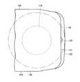
受電ユニット110は、電動車両100の底面に配置されており、カメラ120は、電動車両100の背面101に設けられている。カメラ120は、電動車両100の外部を撮像する。電動車両100内部には、表示部121が設けられており、カメラ120が撮像した電動車両100外部の様子を表示する。受電ユニット110は、電動車両100の前後方向における電動車両100の底面102の中央部より電動車両100の背面101側に配置されている。電動車両100には、蓄電装置150が搭載されている。 The
カメラ120は、電動車両100の底面102および受電ユニット110よりも上方に位置している。背面101の下方には、リヤバンパ122が設けられており、カメラ120は、リヤバンパ122の外周端部の一部を撮像するとともに、リヤバンパ122から電動車両100の後方側の領域を撮像している。 The
なお、カメラ120の撮像エリアRが、カメラ120から下方に向かうにつれて、電動車両100の後方に向かうように設定されているが、カメラ120が、カメラ120の直下に位置する領域をも撮像可能なようにカメラ120を配置してもよい。 In addition, although the imaging area R of the
蓄電装置150を充電する際には、充電効率を確保するために、受電ユニット110と送電ユニット220とを対向させる必要がある。この図1に示す状態では、電動車両100を後退させる必要がある。 When charging the
ここで、運転手は、カメラ120によって撮像された画像を表示部121で確認しながら、電動車両100を後退させる。この図1に示す状態においては、カメラ120の撮像エリアR内に送電ユニット220が位置しており、表示部121には、送電ユニット220が表示される。 Here, the driver moves the
そして、運転手は、送電ユニット220が受電ユニット110と対向するように、電動車両100を移動させる。図2は、電動車両100の移動過程を示す模式図であり、図3は、電動車両100の移動が完了し、受電ユニット110と送電ユニット220とが対向した状態を示す模式図である。 Then, the driver moves the
図2に示すように、受電ユニット110と送電ユニット220とを対向させるために、電動車両100を後進させる過程において、電動車両100の下方に入り込み、送電ユニット220が撮像エリアRから外れる。この際、運転手は、表示部121で送電ユニット220を確認することができない。その一方で、受電ユニット110は、底面102のうち、背面101に近接した位置に設けられている。 As shown in FIG. 2, in order to make the
このため、送電ユニット220が撮像エリアRから外れて、受電ユニット110と送電ユニット220とが対向するまで電動車両100を後進させる距離が短く抑えられている。 For this reason, the distance for moving the
このため、図3に示すように、送電ユニット220が撮像エリアRの外側に外れてから、直ぐに、送電ユニット220と受電ユニット110とが充電可能なように、送電ユニット220と受電ユニット110とが対向する。 Therefore, as illustrated in FIG. 3, the
図4は、電動車両100を移動させる過程において、受電ユニット110および送電ユニット220の位置関係を示す平面図である。 FIG. 4 is a plan view showing the positional relationship between the
図4に示す「D」は、リヤバンパ122によって生じる撮像エリアRの死角領域を示す。実線で示された送電ユニット220は、撮像エリアR内であって死角領域Dから離れた領域に位置している。このため、運転手等は表示部121で送電ユニット220を確認することができる。 “D” shown in FIG. 4 indicates a blind spot area of the imaging area R generated by the
その後、電動車両100が後進方向Bに後進すると、送電ユニット220が死角領域Dに差し掛かる。さらに、電動車両100が後進方向Bに後進すると、送電ユニット220がさらに死角領域D内に入り込むと共に、送電ユニット220がリヤバンパ122および底面102の下側に入り込む。 Thereafter, when the
送電ユニット220のうち、死角領域D内に入り込んだ部分や、リヤバンパ122および底面102下に入り込んだ部分は、撮像エリアRから外れ、表示部121で確認することができない。 Of the
そして、さらに、電動車両100が後進方向Bに後進すると、図中の二点鎖線で示すように、送電ユニット220が完全に、死角領域D、リヤバンパ122または底面102下の領域に入り込み、撮像エリアRから外れる。 Further, when the
ここで、二点鎖線で示された送電ユニット220のうち、最も後方側に位置する部分は、死角領域Dの境界線上に位置している。その後、電動車両100がさらに後進方向Bに後進することで、送電ユニット220と受電ユニット110とが高さ方向に配列する。 Here, among the
図5は、受電ユニット110および送電ユニット220が互いに対向した状態を示す斜視図である。受電ユニット110および送電ユニット220とが対向した状態で、送電ユニット220内に収容された一次自己共振コイルと、受電ユニット110内に収容された二次自己共振コイルと間で、電力の受け渡しがなされる。 FIG. 5 is a perspective view showing a state where the
図4において、運転手が送電ユニット220を表示部121で確認できなくなってから、送電ユニット220が受電ユニット110と対向するまでに間に、電動車両100を動かす距離Lは短い。特に、図4の二点差線に示すように、撮像エリアRの外側に位置したときには、送電ユニット220の一部と受電ユニット110の一部とが既に対向している。 In FIG. 4, the distance L for moving the
このため、運転手は、送電ユニット220が表示部121に表示されなくなってから、僅かに時間が経過した後、電動車両100を停止させることで、受電ユニット110と
送電ユニット220とを完全に対向させることができる。For this reason, the driver completely stops the electric
電動車両100を停車させたときに、仮に、送電ユニット220と受電ユニット110とが位置ずれしたとしても、送電ユニット220と受電ユニット110とのずれ量を小さく抑えることができる。その後、僅かに、電動車両100を前後に動かすことで、受電ユニット110と送電ユニット220とを正確に対向させることができ、受電ユニット110と送電ユニット220とを対向させるための作業負担を軽減することができる。 Even if the
図6は、受電ユニット110の断面図であり、図7は、受電ユニット110の一部を断面視した側面図である。 6 is a cross-sectional view of the
図6に示すように、受電ユニット110は、ケース129と、ケース129内に配置されたボビン128と、ボビン128内に配置されたキャパシタ111とを含む。 As shown in FIG. 6, the
図7に示すように、ボビン128の外周面には、二次自己共振コイル112および二次コイル114が装着されている。 As shown in FIG. 7, the secondary self-
二次コイル114は、二次自己共振コイル112より電動車両100側に配置されており、二次コイル114と二次自己共振コイル112とは互いに高さ方向に間隔をあけて配置されている。二次自己共振コイル112の両端部は、キャパシタ111に接続されている。 The
ケース129は、樹脂ケース132と、この樹脂ケース132の内面に形成されたシールド131とを含む。シールド131は、樹脂ケース132の内周面および天面を覆うように形成されている一方で、下方に向けて開口するように形成されている。シールド131を構成する材料としては、たとえば、フェライトやパーマロイなどの、高透磁率の強磁性体を含んだものが一般的に用いられる。一方、電界を遮蔽する電界シールドとしては、たとえば銅やアルミなどの、電気抵抗が小さい導電体を含んだものが一般的に用いられる。 The
このシールド131は、二次自己共振コイル112の周囲に発生する電磁場が車両の周囲および車両内部に漏洩することを抑制する。この図7に示す例においては、樹脂ケース132は、シールド131の開口部を閉塞する下面を有しているが、樹脂ケース132の下面に開口部を形成するようにしてもよい。 The
二次コイル114は、各種機器を介して、電動車両100に搭載されたバッテリに接続されている。図8は、送電ユニット220の断面図であり、図9は、送電ユニット220の一部を断面視した側面図である。 The
図8および図9に示すように、送電ユニット220も、ケース229と、このケース229内に配置された筒状のボビン228と、このボビン228内に配置されたキャパシタ211とを含む。 As shown in FIGS. 8 and 9, the
ボビン228の外周面には、一次コイル222と、一次自己共振コイル224とが高さ方向に間隔をあけて装着されており、一次自己共振コイル224が一次コイル222の上方に配置されている。ケース229は、樹脂ケース232と、この樹脂ケース232の内周面および底面を覆うように形成されたシールド231とを含む。シールド231は上方に向けて開口するように形成されている。一次自己共振コイル224の両端部は、キャパシタ211に接続されている。一次コイル222は、各種機器を介して外部電源に接続されている。 A
送電ユニット220から受電ユニット110に電力を受け渡すときには、まず、外部電源から一次コイル222に電力が供給され、電磁誘導により一次コイル222から一次自己共振コイル224に電力が伝達される。 When power is transferred from the
一次自己共振コイル224と、図7に示す二次自己共振コイル112との間においては、電磁場の共鳴により、一次自己共振コイル224から二次自己共振コイル112に電力が伝達される。二次自己共振コイル112に伝達された電力は、電磁誘導により二次コイル114に伝達される。二次コイル114に伝達された電力は各種機器を介して電動車両100に搭載されたバッテリに供給される。なお、電力のメカニズムの概要は上記のとおりであるが、その詳細については、後述する。 Between the primary self-
このように、送電ユニット220から受電ユニット110に電力が非接触で伝達されるときには、二次自己共振コイル112の周囲に電磁場が発生する。 Thus, when electric power is transmitted from the
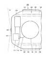
図10は、受電ユニット110から漏れる電磁界の漏洩エリアおよび受電ユニット110等を模式的に示す平面図である。図10において、「R2」は、送電ユニット220から受電ユニット110に電力を伝達する際に、受電ユニット110から漏れる電磁界の漏洩エリアを示す。 FIG. 10 is a plan view schematically showing the leakage area of the electromagnetic field leaking from the
この図10に示すように、受電ユニット110は、電動車両100の背面101、および側面105,106から間隔をあけて配置されている。たとえば、受電ユニット110は、背面101および側面105,106からたとえば、30cm程度間隔をあけて配置されている。 As shown in FIG. 10,
受電ユニット110が、背面101および側面105,106から間隔をあけて配置されているので、電動車両100および受電ユニット110を平面視すると、漏洩エリアR2が電動車両100内に位置している。これにより、送電ユニット220から受電ユニット110に電力を送電するときに、電動車両100の外部に電磁場が漏れることを抑制することができる。具体的には、受電ユニット110から漏れた電磁場が、リヤバンパ122と地面との間や、側面105および側面106の下部と地面との間から電動車両100の周囲に漏れることが抑制されている。これにより、受電ユニット110から漏れた電磁場が電動車両100の周囲に影響を与えることを抑制することができる。 Since the
図11は、車両に搭載された蓄電装置150、受電ユニット110および後輪103,104等の車両搭載機器の配置関係を模式的に示す平面図である。図12は、蓄電装置150、受電ユニット110および後輪103,104等の配置関係を模式的に示す電動車両100の背面図である。 FIG. 11 is a plan view schematically showing an arrangement relationship of vehicle-mounted devices such as
図11および図12に示すように、電動車両100は、電動車両100の幅方向配列する後輪103および後輪104を含む。後輪103は側面105側に配置され、後輪104は側面106側に配置されている。受電ユニット110は、後輪103および後輪104の間に配置されており、側面側から他の車両等によって衝突された時に受電ユニット110は後輪103および後輪104によって保護される。 As shown in FIGS. 11 and 12, electrically
また、受電ユニット110には、図6に示すように、キャパシタ111等の電気機器が搭載されており、これらの電気機器の保護も併せて図ることができる。 In addition, as shown in FIG. 6, the
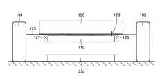
図12において、電動車両100は、フロアパネル125を含み、、フロアパネル125の下面には車両の幅方向に間隔をあけて配置されたフレーム126,127が設けられている。フレーム126,127は、具体的には、リヤフロアメンバであり、フレーム126,127は電動車両100の前後方向に延びるように形成されている。 In FIG. 12, electrically
受電ユニット110は、フロアパネル125の下面に固定されると共に、フレーム126およびフレーム127の間に配置されている。このため、側面側から他の車両等によって衝突された時等に受電ユニット110を保護することができる。 The
受電ユニット110の高さと、フレーム126およびフレーム127の高さとに大きな差はなく、受電ユニット110の側面はフレーム126およびフレーム127によって覆われる。このため、電動車両100の走行中に路面に落ちている石等がタイヤによって跳ね飛ばされたとしても、飛ばされた石等が受電ユニット110に衝突することを抑制することができる。 There is no significant difference between the height of the
フロアパネル125の上面には蓄電装置150が配置されている。蓄電装置150は、受電ユニット110の上方に位置している。図11に示すように、蓄電装置150および受電ユニット110を平面視すると、受電ユニット110と蓄電装置150とは、互いに少なくとも一部が重なるように配置されている。 A
このように、受電ユニット110の直ぐ上に蓄電装置150が配置されているので、受電ユニット110および蓄電装置150を接続するケーブル123を短くすることができる。ケーブル123の短縮化を図ることで、ケーブル123における電気損失を小さく抑えることができ、充電効率の向上を図ることができる。 As described above, since the
なお、この図12などに示す例においては、受電ユニット110は、車両の幅方向中央部に配置されている。このため、たとえば、受電ユニット110と送電ユニット220とを位置あわせする際には、運転手は、表示部121で確認しながら、送電ユニット220が電動車両100の幅方向に中央部に位置するように電動車両100を後進させる。これにより、受電ユニット110および送電ユニット220が車両の幅方向にずれることを抑制することができる。 In the example shown in FIG. 12 and the like, the
図13は、受電ユニット110の搭載位置の第1変形例を示す平面図である。この図13に示すように、電動車両100は、エンジン176を備え、エンジン176は、車両前方側に形成されたエンジンコンパートメント内に搭載されている。 FIG. 13 is a plan view illustrating a first modification of the mounting position of the
エンジン176には、排気管179が接続されており、排気管179は車両の後方に向けて延びている。排気管179の後端部には、マフラー173が接続されている。マフラー173および排気管179の後端部は、車両の幅方向中央部から側面105側にオフセットした位置に設けられている。 An
その一方で、受電ユニット110は、受電ユニット110の幅方向中央部が、電動車両100の幅方向中央部から側面106側にオフセットするように配置されている。このように、マフラー173および排気管179が側面105側に配置される一方で、受電ユニット110は側面106側に配置されているため、マフラー173および排気管179からの熱が受電ユニット110に達しにくくなっている。特に、図12に示すフレーム127およびフレーム126の間で、受電ユニット110を側面106側にオフセットするように配置するのが好ましい。 On the other hand, the
図14は、受電ユニット110およびカメラ120の搭載位置の変形例を示す平面図である。この図14に示す例においては、電動車両100は、前面107と、エンジンコンパートメント169とを含み、エンジンコンパートメント169内には、各種搭載機器が収容されている。 FIG. 14 is a plan view illustrating a modified example of the mounting positions of the
受電ユニット110は、電動車両100の長手方向(前後方向)の中央部から前面107側にオフセットするように配置されている。このため、電動車両100の下方に入り入り込み、カメラ120で確認することができなくなるときの送電ユニット220と、受電ユニット110と送電ユニット220が対向するときの送電ユニット220との間の距離を短くすることができる。 The
このため、この図14に示す例においても、受電ユニット110と送電ユニット220とを対向させるときの作業負担の低減を図ることができる。電動車両100は、電動車両100の幅方向に配列する駆動輪(前輪)181および駆動輪(前輪)182を含む。 For this reason, also in the example shown in FIG. 14, it is possible to reduce the work load when the
受電ユニット110は、駆動輪181と駆動輪182との間に配置されている。このため、側面側から他の車両などが衝突したとしても、受電ユニット110を保護することができる。 The
電動車両100は、電動車両100の幅方向に配列するサイドメンバ133およびサイドメンバ134を含み、受電ユニット110は、サイドメンバ133およびサイドメンバ134の間に配置されている。これにより、側方から他の車両が衝突などしたとしても、受電ユニット110を保護することができる。 The
電動車両100を平面視すると、受電ユニット110はエンジンコンパートメント169内に位置している。エンジンコンパートメント169内には、トランスアクスル170、PCUケース171およびエンジン176などが搭載されている。 When the
この図14に示す例においては、受電ユニット110とPCUケース171とは、ケーブル135によって接続されている。 In the example shown in FIG. 14, the
具体的には、PCUケース171内には、後述するインバータが搭載されており、このインバータと、受電ユニット110内の二次コイル114とを接続する。そして、インバータは、二次コイル114から供給される交流電流を直流電流に変換して、蓄電装置150を充電する。 Specifically, an inverter described later is mounted in the
受電ユニット110およびPCUケース171のいずれもが、エンジンコンパートメント169内に搭載されているため、ケーブル135の長さを短く抑えることができる。これにより、ケーブル135における電気損失の低減を図ることができ、充電効率の向上を図ることができる。 Since both the
図1および図15から図24を用いて、給電設備200を用いて電動車両100を充電する車両用充電システムおよび充電のメカニズムについて説明する。なお、上記の例においては、運転手の操作によって、受電ユニット110と送電ユニット220との位置あわせを行っているが、以下に説明するように、誘導制御を行うことで受電ユニット110と送電ユニット220との位置あわせを行ってもよい。 A vehicle charging system that charges the
図1を参照して、車両用給電システム10は、電動車両100と、給電設備200とを備える。電動車両100は、受電ユニット110と、カメラ120と、通信部130とを含む。通信部130は、電動車両100と給電設備200との間で通信を行なうための通信インターフェースである。 Referring to FIG. 1, a vehicle
給電設備200は、電源装置210と、送電ユニット220と、発光部230と、通信部240とを含む。電源装置210は、たとえば系統電源から供給される商用交流電力を高周波の電力に変換して送電ユニット220へ出力する。なお、電源装置210が生成する高周波電力の周波数は、たとえば1M〜10数MHzである。 The
送電ユニット220は、駐車場の床面に固設され、電源装置210から供給される高周波電力を電動車両100の受電ユニット110へ非接触で送出するように構成される。発光部230は、送電ユニット220上に複数設けられ、送電ユニット220の位置を示すために設けられる。発光部230は、たとえばLEDなどから成る。通信部240は、給電設備200と電動車両100との間で通信を行なうための通信インターフェースである。 The
ここで、給電設備200から電動車両100への給電に際し、電動車両100を給電設備200へ誘導して電動車両100の受電ユニット110と給電設備200の送電ユニット220との位置合わせを行なう必要がある。そして、この図15から図24に示す例においては、電動車両100の給電設備200への駐車制御は2段階で行なわれる。 Here, when power is supplied from the
すなわち、第1段階においては、カメラ120によって撮影される画像に基づいて電動車両100の受電ユニット110と給電設備200の送電ユニット220との位置関係が検知され、その検知結果に基づいて送電ユニット220へ車両を誘導するように車両が制御される。より詳しくは、送電ユニット220上に設けられた複数の発光部230がカメラ120によって撮影され、複数の発光部230の位置および向きが画像認識される。そして、その画像認識の結果に基づいて送電ユニット220と車両との位置および向きが認識され、その認識結果に基づいて送電ユニット220へ車両が誘導される。 That is, in the first stage, the positional relationship between the
ここで、受電ユニット110および送電ユニット220の対向面積は、車体底面の面積よりも小さいところ、送電ユニット220が車体下部に入り込むことによってカメラ120により送電ユニット220を撮影できなくなると、第1段階から第2段階に切替わる。この第2段階においては、送電ユニット220から受電ユニット110への給電が行なわれ、その給電状況に基づいて送電ユニット220と受電ユニット110との距離が検知される。そして、その距離情報に基づいて、送電ユニット220と受電ユニット110との位置合わせを行なうように車両が制御される。 Here, the facing area of the
なお、上記の第2段階時に送電ユニット220から送出される電力の大きさは、送電ユニット220と受電ユニット110との位置合わせの完了後に送電ユニット220から受電ユニット110へ供給される電力よりも小さく設定される。上記第2段階時に送電ユニット220から電力を送出するのは、送電ユニット220と受電ユニット110との間の距離を検知するためであり、本格的な給電を行なう際の大電力は不要だからである。 Note that the magnitude of the power transmitted from the
次に、この実施の形態による車両用給電システム10に用いられる非接触給電方法について説明する。この実施の形態による車両用給電システム10では、共鳴法を用いて給電設備200から電動車両100への給電が行なわれる。 Next, a non-contact power feeding method used in the vehicle
図15は、共鳴法による送電の原理を説明するための図である。図15を参照して、この共鳴法では、2つの音叉が共鳴するのと同様に、同じ固有振動数を有する2つのLC共振コイルが電磁場(近接場)において共鳴することによって、一方のコイルから他方のコイルへ電磁場を介して電力が伝送される。 FIG. 15 is a diagram for explaining the principle of power transmission by the resonance method. Referring to FIG. 15, in this resonance method, in the same manner as two tuning forks resonate, two LC resonance coils having the same natural frequency resonate in an electromagnetic field (near field), and thereby, from one coil. Electric power is transmitted to the other coil via an electromagnetic field.
具体的には、高周波電源310に一次コイル320を接続し、電磁誘導により一次コイル320と磁気的に結合される一次自己共振コイル330へ1M〜10数MHzの高周波電力を給電する。一次自己共振コイル330は、コイル自身のインダクタンスと浮遊容量とによるLC共振器であり、一次自己共振コイル330と同じ共振周波数を有する二次自己共振コイル340と電磁場(近接場)を介して共鳴する。そうすると、一次自己共振コイル330から二次自己共振コイル340へ電磁場を介してエネルギー(電力)が移動する。二次自己共振コイル340へ移動したエネルギー(電力)は、電磁誘導により二次自己共振コイル340と磁気的に結合される二次コイル350によって取出され、負荷360へ供給される。なお、共鳴法による送電は、一次自己共振コイル330と二次自己共振コイル340との共鳴強度を示すQ値がたとえば100よりも大きいときに実現される。 Specifically, the
なお、図1との対応関係については、二次自己共振コイル340および二次コイル350が図1の受電ユニット110に対応し、一次コイル320および一次自己共振コイル330が図1の送電ユニット220に対応する。 1, the secondary self-
図16は、電流源(磁流源)からの距離と電磁界の強度との関係を示した図である。図16を参照して、電磁界は3つの成分を含む。曲線k1は、波源からの距離に反比例した成分であり、「輻射電磁界」と称される。曲線k2は、波源からの距離の2乗に反比例した成分であり、「誘導電磁界」と称される。また、曲線k3は、波源からの距離の3乗に反比例した成分であり、「静電磁界」と称される。 FIG. 16 is a diagram showing the relationship between the distance from the current source (magnetic current source) and the intensity of the electromagnetic field. Referring to FIG. 16, the electromagnetic field includes three components. The curve k1 is a component that is inversely proportional to the distance from the wave source, and is referred to as a “radiated electromagnetic field”. A curve k2 is a component inversely proportional to the square of the distance from the wave source, and is referred to as an “induction electromagnetic field”. The curve k3 is a component inversely proportional to the cube of the distance from the wave source, and is referred to as an “electrostatic magnetic field”.
この中でも波源からの距離とともに急激に電磁波の強度が減少する領域があるが、共鳴法では、この近接場(エバネッセント場)を利用してエネルギー(電力)の伝送が行なわれる。すなわち、近接場を利用して、同じ固有振動数を有する一対の共鳴器(たとえば一対のLC共振コイル)を共鳴させることにより、一方の共鳴器(一次自己共振コイル)から他方の共鳴器(二次自己共振コイル)へエネルギー(電力)を伝送する。この近接場は遠方にエネルギー(電力)を伝播しないので、遠方までエネルギーを伝播する「輻射電磁界」によりエネルギー(電力)を伝送する電磁波に比べて、共鳴法は、より少ないエネルギー損失で送電することができる。 Among these, there is a region where the intensity of the electromagnetic wave rapidly decreases with the distance from the wave source. In the resonance method, energy (electric power) is transmitted using this near field (evanescent field). That is, by using a near field to resonate a pair of resonators (for example, a pair of LC resonance coils) having the same natural frequency, one resonator (primary self-resonant coil) and the other resonator (two Energy (electric power) is transmitted to the next self-resonant coil. Since this near field does not propagate energy (electric power) far away, the resonance method transmits power with less energy loss than electromagnetic waves that transmit energy (electric power) by "radiation electromagnetic field" that propagates energy far away. be able to.
図17は、図1に示した電動車両100の詳細構成図である。図17を参照して、電動車両100は、蓄電装置150と、システムメインリレーSMR1と、昇圧コンバータ162と、インバータ164,166と、モータジェネレータ172,174と、エンジン176と、動力分割装置177と、駆動輪178とを含む。また、電動車両100は、二次自己共振コイル112と、二次コイル114と、整流器140と、DC/DCコンバータ142と、システムメインリレーSMR2と、電圧センサ190とをさらに含む。さらに、電動車両100は、制御装置180と、カメラ120と、通信部130とをさらに含む。 FIG. 17 is a detailed configuration diagram of
この電動車両100は、エンジン176およびモータジェネレータ174を動力源として搭載する。エンジン176およびモータジェネレータ172,174は、動力分割装置177に連結される。そして、電動車両100は、エンジン176およびモータジェネレータ174の少なくとも一方が発生する駆動力によって走行する。エンジン176が発生する動力は、動力分割装置177によって2経路に分割される。すなわち、一方は駆動輪178へ伝達される経路であり、もう一方はモータジェネレータ172へ伝達される経路である。 This
モータジェネレータ172は、交流回転電機であり、たとえばロータに永久磁石が埋設された三相交流同期電動機から成る。モータジェネレータ172は、動力分割装置177によって分割されたエンジン176の運動エネルギーを用いて発電する。たとえば、蓄電装置150の充電状態(「SOC(State Of Charge)」とも称される。)が予め定められた値よりも低くなると、エンジン176が始動してモータジェネレータ172により発電が行なわれ、蓄電装置150が充電される。
モータジェネレータ174も、交流回転電機であり、モータジェネレータ172と同様に、たとえばロータに永久磁石が埋設された三相交流同期電動機から成る。モータジェネレータ174は、蓄電装置150に蓄えられた電力およびモータジェネレータ172により発電された電力の少なくとも一方を用いて駆動力を発生する。そして、モータジェネレータ174の駆動力は、駆動輪178に伝達される。 The
また、車両の制動時や下り斜面での加速度低減時には、運動エネルギーや位置エネルギーとして車両に蓄えられた力学的エネルギーが駆動輪178を介してモータジェネレータ174の回転駆動に用いられ、モータジェネレータ174が発電機として作動する。これにより、モータジェネレータ174は、走行エネルギーを電力に変換して制動力を発生する回生ブレーキとして作動する。そして、モータジェネレータ174により発電された電力は、蓄電装置150に蓄えられる。 Further, when braking the vehicle or reducing acceleration on the down slope, the mechanical energy stored in the vehicle as kinetic energy or positional energy is used for rotational driving of the
動力分割装置177は、サンギヤと、ピニオンギヤと、キャリアと、リングギヤとを含む遊星歯車から成る。ピニオンギヤは、サンギヤおよびリングギヤと係合する。キャリアは、ピニオンギヤを自転可能に支持するとともに、エンジン176のクランクシャフトに連結される。サンギヤは、モータジェネレータ172の回転軸に連結される。リングギヤはモータジェネレータ174の回転軸および駆動輪178に連結される。 Power split device 177 includes a planetary gear including a sun gear, a pinion gear, a carrier, and a ring gear. The pinion gear engages with the sun gear and the ring gear. The carrier supports the pinion gear so as to be able to rotate and is coupled to the crankshaft of the
蓄電装置150は、再充電可能な直流電源であり、たとえばリチウムイオンやニッケル水素などの二次電池から成る。蓄電装置150は、DC/DCコンバータ142から供給される電力を蓄えるほか、モータジェネレータ172,174によって発電される回生電力も蓄える。そして、蓄電装置150は、その蓄えた電力を昇圧コンバータ162へ供給する。なお、蓄電装置150として大容量のキャパシタも採用可能であり、給電設備200(図1)から供給される電力やモータジェネレータ172,174からの回生電力を一時的に蓄え、その蓄えた電力を昇圧コンバータ162へ供給可能な電力バッファであれば如何なるものでもよい。 The
システムメインリレーSMR1は、蓄電装置150と昇圧コンバータ162との間に配設される。システムメインリレーSMR1は、制御装置180からの信号SE1が活性化されると、蓄電装置150を昇圧コンバータ162と電気的に接続し、信号SE1が非活性化されると、蓄電装置150と昇圧コンバータ162との間の電路を遮断する。昇圧コンバータ162は、制御装置180からの信号PWCに基づいて、正極線PL2の電圧を蓄電装置150から出力される電圧以上の電圧に昇圧する。なお、この昇圧コンバータ162は、たとえば直流チョッパ回路から成る。インバータ164,166は、それぞれモータジェネレータ172,174に対応して設けられる。インバータ164は、制御装置180からの信号PWI1に基づいてモータジェネレータ172を駆動し、インバータ166は、制御装置180からの信号PWI2に基づいてモータジェネレータ174を駆動する。なお、インバータ164,166は、たとえば三相ブリッジ回路から成る。 System main relay SMR1 is arranged between
二次自己共振コイル112は、LC共振コイルであり、給電設備200の一次自己共振コイルと電磁場を介して共鳴することにより給電設備200から受電する。なお、二次自己共振コイル112の容量成分は、コイルの両端に接続されるコンデンサとされている。この二次自己共振コイル112については、給電設備200の一次自己共振コイルとの距離や、一次自己共振コイルおよび二次自己共振コイル112の共鳴周波数等に基づいて、一次自己共振コイルと二次自己共振コイル112との共鳴強度を示すQ値(たとえば、Q>100)およびその結合度を示すκ等が大きくなるようにその巻数が適宜設定される。 The secondary self-
二次コイル114は、二次自己共振コイル112と同軸上に配設され、電磁誘導により二次自己共振コイル112と磁気的に結合可能である。この二次コイル114は、二次自己共振コイル112により受電された電力を電磁誘導により取出して整流器140へ出力する。なお、二次自己共振コイル112および二次コイル114は、図1に示した受電ユニット110を形成する。 The
整流器140は、二次コイル114によって取出された交流電力を整流する。DC/DCコンバータ142は、制御装置180からの信号PWDに基づいて、整流器140によって整流された電力を蓄電装置150の電圧レベルに変換して蓄電装置150へ出力する。システムメインリレーSMR2は、DC/DCコンバータ142と蓄電装置150との間に配設される。システムメインリレーSMR2は、制御装置180からの信号SE2が活性化されると、蓄電装置150をDC/DCコンバータ142と電気的に接続し、信号SE2が非活性化されると、蓄電装置150とDC/DCコンバータ142との間の電路を遮断する。電圧センサ190は、整流器140とDC/DCコンバータ142との間の電圧VHを検出し、その検出値を制御装置180へ出力する。 The
制御装置180は、アクセル開度や車両速度、その他種々のセンサからの信号に基づいて、昇圧コンバータ162およびモータジェネレータ172,174をそれぞれ駆動するための信号PWC,PWI1,PWI2を生成し、その生成した信号PWC,PWI1,PWI2をそれぞれ昇圧コンバータ162およびインバータ164,166へ出力する。そして、車両の走行時、制御装置180は、信号SE1を活性化してシステムメインリレーSMR1をオンさせるとともに、信号SE2を非活性化してシステムメインリレーSMR2をオフさせる。
また、給電設備200(図1)から電動車両100への給電が行なわれるとき、制御装置180は、カメラ120によって撮影された画像をカメラ120から受ける。また、制御装置180は、給電設備200から送出される電力の情報(電圧および電流)を給電設備200から通信部130を介して受け、電圧センサ190によって検出される電圧VHの検出値を電圧センサ190から受ける。そして、制御装置180は、これらのデータに基づいて、給電設備200の送電ユニット220(図1)へ当該車両を誘導するように後述の方法により車両の駐車制御を実行する。 When power is supplied from the power supply facility 200 (FIG. 1) to the
送電ユニット220への駐車制御が完了すると、制御装置180は、通信部130を介して給電設備200へ給電指令を送信するとともに、信号SE2を活性化してシステムメインリレーSMR2をオンさせる。そして、制御装置180は、DC/DCコンバータ142を駆動するための信号PWDを生成し、その生成した信号PWDをDC/DCコンバータ142へ出力する。 When the parking control to
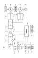
図18は、図17に示した制御装置180の機能ブロック図である。図18を参照して、制御装置180は、IPA(Intelligent Parking Assist)−ECU(Electronic Control Unit)410と、EPS(Electric Power Steering)420と、MG(Motor-Generator)−ECU430と、ECB(Electronically Controlled Brake)440と、EPB(Electric Parking Brake)450と、共鳴ECU460と、HV(Hybrid Vehicle)−ECU470とを含む。 FIG. 18 is a functional block diagram of
IPA−ECU410は、車両の動作モードが充電モードのとき、カメラ120から受ける画像情報に基づいて、給電設備200の送電ユニット220(図1)へ車両を誘導する誘導制御を実行する(第1の誘導制御)。具体的には、IPA−ECU410は、カメラ120から受ける画像情報に基づいて送電ユニット220を認識する。ここで、送電ユニット220には、送電ユニット220の位置および向きを示す複数の発光部230が設けられており、IPA−ECU410は、カメラ120に映し出された複数の発光部230の映像に基づいて送電ユニット220との位置関係(おおよその距離および向き)を認識する。そして、IPA−ECU410は、その認識結果に基づいて、送電ユニット220へ適切な向きで車両が誘導されるようにEPS420へ指令を出力する。 When the operation mode of the vehicle is the charging mode, IPA-
また、IPA−ECU410は、送電ユニット220に車両が近づくことによって送電ユニット220が車体下部に入り込み、カメラ120によって送電ユニット220を撮影できなくなると、カメラ120からの画像情報に基づく誘導制御(第1の誘導制御)の終了をHV−ECU470へ通知する。EPS420は、第1の誘導制御時、IPA−ECU410からの指令に基づいてステアリングの自動制御を行なう。 Further, when the vehicle approaches the
MG−ECU430は、HV−ECU470からの指令に基づいて、モータジェネレータ172,174および昇圧コンバータ162を制御する。詳しくは、MG−ECU430は、モータジェネレータ172,174および昇圧コンバータ162を駆動するための信号を生成してそれぞれインバータ164,166および昇圧コンバータ162へ出力する。 MG-
ECB440は、HV−ECU470からの指令に基づいて、車両の制動を制御する。詳しくは、ECB440は、HV−ECU470からの指令に基づいて、油圧ブレーキの制御を行なうとともに、油圧ブレーキとモータジェネレータ174による回生ブレーキとの協調制御を行なう。EPB450は、HV−ECU470からの指令に基づいて、電動パーキングブレーキの制御を行なう。 The
共鳴ECU460は、給電設備200(図1)から送出される電力の情報を給電設備200から通信部130を介して受ける。また、共鳴ECU460は、車両における受電電圧を示す電圧VHの検出値を電圧センサ190(図17)から受ける。そして、共鳴ECU460は、たとえば給電設備200からの送電電圧と電圧VHとを比較することによって、給電設備200の送電ユニット220と車両の受電ユニット110との距離を検知する。 The
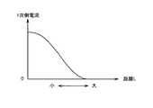
具体的には、図19に示すような一定の一次側電圧(給電設備200からの出力電圧)に対して、二次側電圧(電動車両100の受電電圧)は、図20に示すように、給電設備200の送電ユニット220と電動車両100の受電ユニット110との間の距離Lに応じて変化する。そこで、この図19,20に示される一次側電圧および二次側電圧の関係を予め測定するなどしてマップ等を作成しておき、二次側電圧を示す電圧VHの検出値に基づいて送電ユニット220と受電ユニット110との間の距離を検知することができる。 Specifically, for a certain primary side voltage (output voltage from the power supply facility 200) as shown in FIG. 19, the secondary side voltage (the received voltage of the electric vehicle 100) is as shown in FIG. It changes in accordance with the distance L between the
なお、図21に示すように、送電ユニット220と受電ユニット110との間の距離Lに応じて一次側電流(給電設備200からの出力電流)は変化するところ、この関係を用いて、給電設備200からの出力電流の検出値に基づいて送電ユニット220と受電ユニット110との間の距離を検知してもよい。 In addition, as shown in FIG. 21, the primary side current (output current from the power supply facility 200) changes according to the distance L between the
再び図18を参照して、共鳴ECU460は、送電ユニット220と受電ユニット110との間の距離を検知すると、その距離情報をHV−ECU470へ出力する。また、共鳴ECU460は、HV−ECU470から充電開始指令を受けると、システムメインリレーSMR2へ出力される信号SE2を活性化することによってシステムメインリレーSMR2をオンさせる。そして、共鳴ECU460は、DC/DCコンバータ142を駆動するための信号を生成してDC/DCコンバータ142へ出力する。 Referring to FIG. 18 again, upon detecting the distance between
HV−ECU470は、車両の動作モードが走行モードのとき、アクセルペダル/ブレーキペダルの操作状況や車両の走行状況等に応じて、MG−ECU430およびECB440へ制御指令を出力する。また、パーキングブレーキスイッチが操作される等して運転者によりパーキングブレーキの作動が指示されると、HV−ECU470は、EPB450へ動作指令を出力する。 HV-
一方、車両の動作モードが充電モードのとき、HV−ECU470は、通信部130によって給電設備200(図1)との通信を確立し、給電設備200を起動するための起動指令を通信部130を介して給電設備200へ出力する。給電設備200が起動すると、HV−ECU470は、給電設備200の送電ユニット220上に設けられる発光部230の点灯指令を通信部130を介して給電設備200へ出力する。そして、発光部230が点灯すると、HV−ECU470は、電動車両100を送電ユニット220へ誘導する誘導制御を実行中であることを示す誘導制御中信号を通信部130を介して給電設備200へ出力するとともに、カメラ120からの画像情報に基づく誘導制御(第1の誘導制御)の実行を指示する指令をIPA−ECU410へ出力する。 On the other hand, when the operation mode of the vehicle is the charging mode, HV-
さらに、HV−ECU470は、第1の誘導制御の終了通知をIPA−ECU410から受けると、送電ユニット220と受電ユニット110との距離情報に基づく誘導制御を実行する(第2の誘導制御)。具体的には、HV−ECU470は、給電設備200の送電ユニット220と車両の受電ユニット110との距離情報を共鳴ECU460から受け、その距離情報に基づいて、送電ユニット220と受電ユニット110との距離が最小となるように、車両の駆動および制動をそれぞれ制御するMG−ECU430およびECB440へ指令を出力する。 Further, when receiving an end notification of the first guidance control from the IPA-
なお、送電ユニット220と受電ユニット110との距離が最小であることの判断は、たとえば、図22に示すように、共鳴ECU460から受ける送電ユニット220と受電ユニット110との距離Lの微分値が零となるときに基づいてなされる。 The determination that the distance between the
再び図18を参照して、送電ユニット220と受電ユニット110との位置合わせが完了すると、HV−ECU470は、EPB450へ動作指令を出力し、その後、給電設備200からの給電を指示する給電指令を通信部130を介して給電設備200へ出力するとともに共鳴ECU460へ充電開始指令を出力する。 Referring to FIG. 18 again, when the alignment between
この制御装置180においては、車両の動作モードが充電モードになると、HV−ECU470は、通信部130によって給電設備200との通信を確立し、通信部130を介して給電設備200へ起動指令を送信する。起動指令に応じて給電設備200が起動すると、HV−ECU470は、通信部130を介して給電設備200へ発光部230の点灯指令を送信する。送電ユニット220上の発光部230が点灯すると、HV−ECU470は、通信部130を介して給電設備200へ誘導制御中信号を送信するとともに、カメラ120からの画像情報に基づく誘導制御(第1の誘導制御)の実行を指示する指令をIPA−ECU410へ出力する。 In this
IPA−ECU410は、HV−ECU470から指令を受けると、カメラ120からの画像情報に基づく誘導制御(第1の誘導制御)を実行し、ステアリングを自動制御するための指令をEPS420へ出力する。そして、車両が送電ユニット220へ近づくことにより送電ユニット220が車体下部へ入り込み、カメラ120によって送電ユニット220を認識不可になると、IPA−ECU410は、第1の誘導制御の終了をHV−ECU470へ通知する。 When receiving a command from the HV-
一方、共鳴ECU460は、上記の誘導制御中信号に応じて給電設備200から送出される電力(上述のように、この電力は、駐車制御完了後に供給される電力よりも小さい。)の情報を給電設備200から通信部130を介して受け、電動車両100の受電電圧を示す電圧VHの検出値を電圧センサ190から受ける。そして、共鳴ECU460は、給電設備200から電動車両100への給電状況に基づいて送電ユニット220と受電ユニット110との間の距離を推定し、その距離情報をHV−ECU470へ出力する。HV−ECU470は、カメラ120からの画像情報に基づく第1の誘導制御の終了通知をIPA−ECU410から受けると、共鳴ECU460から受ける送電ユニット220と受電ユニット110との距離情報に基づく誘導制御(第2の誘導制御)を実行し、車両の駆動および制動を自動制御するための指令をそれぞれMG−ECU430およびECB440へ出力する。 On the other hand, the
そして、上記第2の誘導制御により送電ユニット220と受電ユニット110との位置合わせが完了すると、HV−ECU470は、EPB450へ動作指令を出力し、その後、通信部130を介して給電設備200へ給電指令を出力するとともに共鳴ECU460へ充電開始指令を出力する。これにより、給電設備200から電動車両100への実質的な給電が開始される。 When the positioning between the
図23は、図1に示した給電設備200の機能ブロック図である。図23を参照して、給電設備200は、交流電源250と、高周波電力ドライバ260と、一次コイル222と、一次自己共振コイル224と、電圧センサ272と、電流センサ274と、発光部230と、通信部240と、ECU270とを含む。 FIG. 23 is a functional block diagram of the
交流電源250は、車両外部の電源であり、たとえば系統電源である。高周波電力ドライバ260は、交流電源250から受ける電力を高周波の電力に変換し、その変換した高周波電力を一次コイル222へ供給する。なお、高周波電力ドライバ260が生成する高周波電力の周波数は、たとえば1M〜10数MHzである。
一次コイル222は、一次自己共振コイル224と同軸上に配設され、電磁誘導により一次自己共振コイル224と磁気的に結合可能である。そして、一次コイル222は、高周波電力ドライバ260から供給される高周波電力を電磁誘導により一次自己共振コイル224へ給電する。
一次自己共振コイル224は、電動車両100の二次自己共振コイル112と同様にLC共振コイルであり、電動車両100の二次自己共振コイル112と電磁場を介して共鳴することにより電動車両100へ電力を送電する。なお、一次自己共振コイル224の容量成分も、コイルの両端に接続されるコンデンサとされている。この一次自己共振コイル224も、電動車両100の二次自己共振コイル112との距離や、一次自己共振コイル224および二次自己共振コイル112の共鳴周波数等に基づいて、Q値(たとえば、Q>100)および結合度κ等が大きくなるようにその巻数が適宜設定される。 The primary self-
なお、一次自己共振コイル224および一次コイル222は、図1に示した送電ユニット220を形成する。発光部230および通信部240は、図1で説明したとおりである。電圧センサ272は、高周波電力ドライバ260から出力される電圧VSを検出し、その検出値をECU270へ出力する。電流センサ274は、高周波電力ドライバ260から出力される電流ISを検出し、その検出値をECU270へ出力する。 The primary self-
ECU270は、電動車両100から通信部240を介して起動指令を受けると、給電設備200を起動する。また、ECU270は、電動車両100から通信部240を介して発光部230の点灯指令を受けると、発光部230を点灯させる。そして、ECU270は、電動車両100から通信部240を介して給電指令を受けると、給電設備200から電動車両100へ供給される電力が目標値に一致するように高周波電力ドライバ260の出力を制御する。 When
また、ECU270は、電動車両100から通信部240を介して誘導制御中信号を受けているとき、電圧センサ272からの電圧VSおよび電流センサ274からの電流ISの各検出値を含む給電設備200の電力情報を通信部240を介して電動車両100へ送信する。そして、ECU270は、誘導制御中信号の受信中、給電指令に基づく給電実行時の電力よりも小さい所定の電力を出力するように高周波電力ドライバ260の出力を制御する。 In addition, when receiving an in-guidance control signal from the
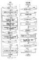
図24は、電動車両100の制御装置180および給電設備200のECU260により実行される車両の誘導制御を説明するためのフローチャートである。なお、このフローチャートの処理は、一定時間毎または所定の条件が成立する毎に実行される。 FIG. 24 is a flowchart for illustrating vehicle guidance control executed by
図24を参照して、電動車両100において、制御装置180は、車両の動作モードが充電モードであるか否かを判定する(ステップS10)。非充電モード時すなわち走行モード時は(ステップS10においてNO)、制御装置180は、以降の一連の処理を実行することなくステップS120へ処理を移行する。 Referring to FIG. 24, in electrically
ステップS10において充電モードであると判定されると(ステップS10においてYES)、制御装置180は、車両の通信部130と給電設備200の通信部240との通信を確立し、給電設備200の起動を指示する起動指令を通信部130によって給電設備200へ送信する(ステップS20)。次いで、制御装置180は、給電設備200の送電ユニット220上に設けられる発光部230の点灯要求があると(ステップS25においてYES)、発光部230の点灯を指示する点灯指令を通信部130によって給電設備200へ送信する(ステップS30)。さらに次いで、制御装置180は、送電ユニット220への車両の誘導制御中であることを示す誘導制御中信号を通信部130によって給電設備200へ送信し、送電ユニット220と受電ユニット110との位置合わせが完了するまで送信を継続する(ステップS40)。 When it is determined in step S10 that the charging mode is set (YES in step S10),
そして、制御装置180は、上述の方法により、カメラ120からの画像情報に基づく誘導制御(第1の誘導制御)を実行する(ステップS50)。この第1の誘導制御は、電動車両100が給電設備200へ近づくことにより送電ユニット220が車体下部に入り込むことによってカメラ120からの画像情報に基づき送電ユニット220を認識できなくなるまで実行される(ステップS60)。 And the
カメラ120からの画像情報に基づいて送電ユニット220を認識できなくなると(ステップS60においてYES)、制御装置180は、給電設備200から送信される電力情報(給電設備200からの出力電圧および電流)に基づいて送電ユニット220と受電ユニット110との距離を上記の方法により推定する。そして、制御装置180は、送電ユニット220から受電ユニット110への給電状況に基づいて推定された上記の距離情報に基づく誘導制御(第2の誘導制御)を実行する(ステップS70)。 If
第2の誘導制御中、制御装置180は、送電ユニット220と受電ユニット110との距離の微分値に基づいて、上述した方法により送電ユニット220と受電ユニット110との距離が極小になったか否かを判定する(ステップS80)。そして、送電ユニット220と受電ユニット110との距離が極小になったと判定されると(ステップS80においてYES)、制御装置180は、車両を停車させ、電動パーキングブレーキを作動させる(ステップS90)。 During the second guidance control, the
その後、制御装置180は、給電設備200から電動車両100への実質的な給電を指示する給電指令を通信部130によって給電設備200へ送信する(ステップS100)。さらに、制御装置180は、システムメインリレーSMR2をオンするとともにDC/DCコンバータ142を駆動し、蓄電装置150の充電制御を実行する(ステップS110)。 Thereafter,
一方、給電設備200においては、電動車両100から送信された起動指令を通信部240が受信すると(ステップS200においてYES)、ECU270は、給電設備200の起動を行なう(ステップS210)。次いで、電動車両100から送信された点灯指令を通信部240が受信すると(ステップS220においてYES)、ECU270は、発光部230を点灯する(ステップS230)。さらに次いで、電動車両100から送信される誘導制御中信号を通信部240が受信すると(ステップS240においてYES)、ECU270は、充電時よりも小さい予め設定された電力を出力するように高周波電力ドライバ260の出力を制御する(ステップS250)。 On the other hand, in
誘導制御中信号の受信中、ECU270は、給電設備200から出力される電圧の大きさを示す電圧センサ272からの電圧VSの検出値、および給電設備200から出力される電流の大きさを示す電流センサ274からの電流ISの検出値を、給電設備200の電力情報として通信部240によって電動車両100へ送信する(ステップS260)。 During reception of the in-guidance control signal, the
そして、電動車両100から送信される給電指令を通信部240が受信すると(ステップS270においてYES)、ECU270は、車両の充電を行なうための充電電力を出力するように高周波電力ドライバ260の出力を制御する(ステップS280)。 When
以上のように、図15から図24に示す誘導制御においては、電動車両100の駐車制御は2段階で行なわれる。第1段階では、車両に搭載されたカメラ120からの画像情報に基づいて送電ユニット220と受電ユニット110との位置関係が検知され、その検知結果に基づいて、送電ユニット220へ車両を誘導するように車両が制御される(第1の誘導制御)。第2段階では、送電ユニット220から受電ユニット110への給電状況に基づいて送電ユニット220と受電ユニット110との間の距離Lが検知される。そして、送電ユニット220が車体下部に入り込むことによりカメラ120で送電ユニット220を撮影できない距離まで車両が送電ユニット220に近づくと、送電ユニット220から受電ユニット110への給電状況に基づき検知された送電ユニット220と受電ユニット110との距離情報に基づいて、送電ユニット220と受電ユニット110との位置合わせを行なうように車両が制御される(第2の誘導制御)。これにより、大掛かりな設備を備えることなく、給電設備200の送電ユニット220と車両に搭載された受電ユニット110との位置合わせを行なうことができる。したがって、図15から図24に示す誘導制御よれば、給電設備200への駐車精度を確保しつつ簡易な構成で車両用給電システム10を実現することができる。 As described above, in the guidance control shown in FIGS. 15 to 24, parking control of electrically
また、図15から図24に示す誘導制御においては、給電設備200と電動車両100との距離が大きいときは、画像情報に基づく誘導制御(第1の誘導制御)とし、給電設備200と電動車両100との距離が小さくなってから、送電ユニット220からの送電を必要とする、距離情報に基づく誘導制御(第2の誘導制御)が実行される。さらに、第2の誘導制御時に送電ユニット220から出力される電力は、充電制御開始後に出力される電力よりも小さい。したがって、図15から図24に示す誘導制御よれば、電力の消費を抑えることができる。特に、本実施の形態に係る電動車両100によれば、送電ユニット220が撮像エリアRから外れてから受電ユニット110と対向するまでの距離が短いため、距離情報に基づく誘導制御の期間を短くすることができ、距離情報に基づく誘導制御の際に消費する電力を小さく抑えることができる。 Further, in the guidance control shown in FIGS. 15 to 24, when the distance between the
本実施の形態に係る電動車両100によれば、受電ユニット110と送電ユニット220とを位置あわせする過程において、送電ユニット220がカメラ120の撮像エリアRから外れる期間を短く抑えられている。画像表示に基づく誘導制御(第1の誘導制御)の誘導精度の方が、距離情報に基づく誘導制御(第2の誘導制御)の誘導精度の方が高い。このため、受電ユニット110と送電ユニット220とを位置合わせする過程において、画像表示に基づく誘導制御の期間を長くすることができ、位置あわせ精度を高めることができる。 According to electrically
さらに、距離情報に基づく誘導制御を行うときには、受電ユニット110と送電ユニット220とは互いに一部が高さ方向に重なりあっており、距離情報に基づく誘導制御の誘導精度も高めることができる。 Furthermore, when performing the guidance control based on the distance information, the
また、図15から図24に示す誘導制御においては、給電設備200から給電を受ける電動車両100からの指令に基づいて給電設備200が起動され、さらに、電動車両100からの指令に基づいて発光部230が点灯される。したがって、この図15から図24に示す誘導制御によれば、非充電時の無駄な電力消費を抑えることができる。 Further, in the guidance control shown in FIGS. 15 to 24, the
なお、図15から図24に示す誘導制御においては、送電ユニット220がカメラ120の死角に入るとカメラ120からの画像情報に基づく第1の誘導制御から距離情報に基づく第2の誘導制御に切替わるものとしたが、予め設定された所定の距離まで車両が送電ユニット220に近づいたときに第1の誘導制御から第2の誘導制御に切り替わるようにしてもよい。なお、上記所定の距離として、たとえば、受電ユニット110が送電ユニット220から受電可能な距離などを設定可能である。 15 to 24, when the
また、図15から図24に示す誘導制御においては、給電設備200の電力情報を電動車両100へ送信し、その電力情報に基づいて車両側で距離情報を生成するものとしたが、給電設備200における出力電流に基づいて、または車両における受電電圧を電動車両100から給電設備200へ送信することによって、給電設備200側で距離情報を生成して電動車両100へ送信してもよい。また、距離情報を給電設備200が有することによって、給電設備200において距離情報に基づく第2の誘導制御の終了判定を行なってもよい。 In the guidance control shown in FIGS. 15 to 24, the power information of the
また、図15から図24に示す誘導制御においては、第1の誘導制御時は運転者がアクセル/ブレーキを操作するものとし、第2の誘導制御時はアクセル/ブレーキ操作を自動で行なうものとしたが、第1の誘導制御時もアクセル/ブレーキ操作も自動で行なうようにしてもよいし、あるいは、第2の誘導制御時も運転者がアクセル/ブレーキを操作するものとしてもよい。 Further, in the guidance control shown in FIGS. 15 to 24, the driver operates the accelerator / brake during the first guidance control, and the accelerator / brake operation is automatically performed during the second guidance control. However, the accelerator / brake operation may be automatically performed during the first guidance control, or the driver may operate the accelerator / brake during the second guidance control.
また、図15から図24に示す誘導制御においては、カメラ120は車両後部に配設されるものとしたが、カメラ120の配設場所は車両後部に限定されるものではない。 In the guidance control shown in FIGS. 15 to 24, the
また、図15から図24に示す誘導制御においては、共鳴法を用いて給電設備200から電動車両100へ非接触で送電するものとしたが、給電設備200から電動車両100への送電手法は、必ずしも共鳴法に限定されるものではなく、その他の非接触送電手法である、電磁誘導を用いた送電や、マイクロ波を用いた送電であってもよい。なお、これらの送電手法においても、給電設備から車両への給電状況に基づいて送電ユニットと受電ユニットとの距離を推定することが可能である。 In addition, in the guidance control shown in FIGS. 15 to 24, power is transmitted from the
また、図15から図24に示す誘導制御においては、発光部230に基づいて送電ユニット220の位置および方向を画像認識するものとしたが、発光部230を設けることなく送電ユニット220の形状等を画像認識してもよい。なお、図15から図24に示す誘導制御のように発光部230を設けることによって、夜間においても送電ユニット220の位置および方向を認識することが可能である。 Further, in the guidance control shown in FIGS. 15 to 24, the position and direction of the
また、図15から図24に示す誘導制御においては、一対の自己共振コイルを共鳴させて送電するものとしたが、共鳴体として自己共振コイルに代えて高誘電率材から成る高誘電体ディスクを用いることもできる。 Further, in the induction control shown in FIGS. 15 to 24, power is transmitted by resonating a pair of self-resonant coils. However, instead of the self-resonant coil, a high dielectric disk made of a high dielectric constant material is used as a resonator. It can also be used.
また、図15から図24に示す誘導制御においては、電動車両として、動力分割装置177によりエンジン176の動力を分割して駆動輪178とモータジェネレータ172とに伝達可能なシリーズ/パラレル型のハイブリッド車について説明したが、この発明は、その他の形式のハイブリッド車にも適用可能である。すなわち、たとえば、モータジェネレータ172を駆動するためにのみエンジン176を用い、モータジェネレータ174でのみ車両の駆動力を発生する、いわゆるシリーズ型のハイブリッド車や、エンジン176が生成した運動エネルギーのうち回生エネルギーのみが電気エネルギーとして回収されるハイブリッド車、エンジンを主動力として必要に応じてモータがアシストするモータアシスト型のハイブリッド車などにもこの発明は適用可能である。 In addition, in the guidance control shown in FIGS. 15 to 24, as an electric vehicle, a series / parallel type hybrid vehicle capable of dividing the power of the
また、この発明は、エンジン176を備えずに電力のみで走行する電気自動車や、直流電源として蓄電装置150に加えて燃料電池をさらに備える燃料電池車にも適用可能である。また、この発明は、昇圧コンバータ162を備えない電動車両や、DC/DCコンバータ142を備えない電動車両にも適用可能である。 In addition, the present invention can also be applied to an electric vehicle that does not include
なお、図15から図24に示す誘導制御において、カメラ120およびIPA−ECU410は、この発明における「第1の検知手段」(第1の検知部)を形成し、IPA−ECU410およびEPS420は、この発明における「第1の誘導制御手段」(第1の誘導制御部)を形成する。また、共鳴ECU460は、この発明における「第2の検知手段」(第2の検知部)に対応し、HV−ECU470、MG−ECU430およびECB440は、この発明における「第2の誘導制御手段」(第2の誘導制御部)を形成する。 In the guidance control shown in FIGS. 15 to 24, the
さらに、カメラ120は、この発明における「撮影装置」に対応し、IPA−ECU410は、この発明における「画像認識部」に対応する。また、さらに、通信部130,240は、この発明における「通信手段」を形成し、一次自己共振コイル224は、この発明における「送電用コイル」に対応する。また、さらに、二次自己共振コイル112は、この発明における「受電用コイル」に対応し、共鳴ECU460は、この発明における「距離推定部」に対応する。また、さらに、EPS420は、この発明における「第1の制御部」に対応し、MG−ECU430およびECB440は、この発明における「第2の制御部」を形成する。また、さらに、高周波電力ドライバ260およびECU270は、この発明における「電力制御部」を形成する。 Further,
今回開示された実施の形態は、すべての点で例示であって制限的なものではないと考えられるべきである。本発明の範囲は、上記した実施の形態の説明ではなくて請求の範囲によって示され、請求の範囲と均等の意味および範囲内でのすべての変更が含まれることが意図される。 The embodiment disclosed this time should be considered as illustrative in all points and not restrictive. The scope of the present invention is shown not by the above description of the embodiments but by the scope of claims, and is intended to include all modifications within the meaning and scope equivalent to the scope of claims.
本発明は、電動車両に適用することができ、特に、非接触で車両外部に設けられた送電コイルから受電可能な電動車両に好適である。 The present invention can be applied to an electric vehicle, and is particularly suitable for an electric vehicle that can receive power from a power transmission coil provided in a non-contact manner outside the vehicle.
10 車両用給電システム、100 電動車両、101 背面、102 底面、103,104 後輪、105,106 側面、107 前面、110 受電ユニット、111 キャパシタ、112 二次自己共振コイル、114 二次コイル、120 カメラ、121 表示部、122 リヤバンパ、123 ケーブル、125 フロアパネル、126,127 フレーム、128 ボビン、129 ケース、130,240 通信部、131 シールド、132 樹脂ケース、133,134 サイドメンバ、135 ケーブル、140 整流器、142 コンバータ、150 蓄電装置、162 昇圧コンバータ、164,166 インバータ、169 エンジンコンパートメント、170 トランスアクスル、171 ケース、172,174 モータジェネレータ、176 エンジン、177 動力分割装置、178 駆動輪、179 排気管、180 制御装置、181,182 駆動輪、190 電圧センサ、200 給電設備、210 電源装置、211 キャパシタ、220 送電ユニット、222 一次コイル、224 一次自己共振コイル、228 ボビン、229 ケース、230 発光部、231 シールド、232 樹脂ケース、250 交流電源、260 高周波電力ドライバ、272 電圧センサ、274 電流センサ。 DESCRIPTION OF
Claims (10)
Translated fromJapanese前記車両の底面に配置され、電磁場の共鳴により前記送電コイルから電力を受電可能な受電コイルと、
前記車両の外部を撮像する撮像装置と、
前記撮像装置が撮像した前記車両の外部を表示する表示部と、
を備え、
前記受電コイルは、前記車両の前後方向における前記底面の中央部から前記撮像装置が設けられた周面側にずれた位置に配置された、車両。A vehicle that receives electric power in a non-contact manner from a power transmission coil provided outside,
A power receiving coil disposed on the bottom surface of the vehicle and capable of receiving power from the power transmitting coil by electromagnetic field resonance;
An imaging device for imaging the outside of the vehicle;
A display unit for displaying the outside of the vehicle imaged by the imaging device;
With
The vehicle, wherein the power receiving coil is disposed at a position shifted from a central portion of the bottom surface in the front-rear direction of the vehicle toward a peripheral surface side where the imaging device is provided.
前記受電コイルは、前記車両の前後方向における前記底面の中央部から前記背面側にずれた位置に設けられた、請求項1に記載の車両。The imaging device is provided on the back of the vehicle,
The vehicle according to claim 1, wherein the power reception coil is provided at a position shifted from a central portion of the bottom surface in the front-rear direction of the vehicle toward the back side.
前記受電コイルは、前記後輪の間に設けられた、請求項2に記載の車両。A pair of rear wheels provided at intervals in the width direction of the vehicle,
The vehicle according to claim 2, wherein the power receiving coil is provided between the rear wheels.
前記ボビンの内部に配置された電気機器と、
をさらに備えた、請求項3に記載の車両。A hollow bobbin on which the power receiving coil is mounted;
An electrical device disposed inside the bobbin;
The vehicle according to claim 3, further comprising:
前記受電コイルは、前記第1サイドフレームと前記第2サイドフレームとの間に配置された、請求項1から請求項4のいずれかに記載の車両。The vehicle further comprises a first side frame and a second side frame that extend in the front-rear direction of the vehicle and are arranged in the width direction of the vehicle,
The vehicle according to any one of claims 1 to 4, wherein the power reception coil is disposed between the first side frame and the second side frame.
前記バッテリは、前記受電コイルの上方に配置された、請求項1から請求項5のいずれかに記載の車両。Further comprising a battery mounted in the vehicle;
The vehicle according to any one of claims 1 to 5, wherein the battery is disposed above the power receiving coil.
前記エンジンに接続された排気管とをさらに備え、
前記排気管は、前記底面に配置されると共に、前記車両の一方の側面側に配置され、前記受電コイルは、他方の側面側に配置された、請求項1に記載の車両。Engine,
An exhaust pipe connected to the engine,
The vehicle according to claim 1, wherein the exhaust pipe is disposed on the bottom surface and is disposed on one side surface of the vehicle, and the power reception coil is disposed on the other side surface side.
前記第1の検知部の検知結果に基づいて、前記送電ユニットへ前記車両を誘導するように前記車両を制御する第1の誘導制御部と、
前記送電ユニットから前記受電ユニットへの給電状況に基づいて前記送電ユニットと前記受電ユニットとの間の距離を検知する第2の検知部と、
前記第1の誘導制御部により前記車両が前記送電ユニットに所定の距離まで近づくと、前期第2の検知部の検知結果に基づいて前記送電ユニットと前記受電ユニットとの位置あわせを行うように、前記車両を制御する第2の誘導制御部と、
を備えた、請求項1から請求項7のいずれかに記載の車両。A first detection unit that detects a positional relationship between a power transmission unit including the power transmission coil and a power reception unit including the power reception coil;
A first guidance control unit for controlling the vehicle to guide the vehicle to the power transmission unit based on a detection result of the first detection unit;
A second detection unit that detects a distance between the power transmission unit and the power reception unit based on a power supply state from the power transmission unit to the power reception unit;
When the vehicle approaches the power transmission unit to a predetermined distance by the first guidance control unit, the power transmission unit and the power reception unit are aligned based on the detection result of the second detection unit in the previous period. A second guidance control unit for controlling the vehicle;
The vehicle according to claim 1, comprising:
Priority Applications (8)
| Application Number | Priority Date | Filing Date | Title |
|---|---|---|---|
| JP2010058793AJP5051257B2 (en) | 2010-03-16 | 2010-03-16 | vehicle |
| PCT/IB2011/000502WO2011114208A2 (en) | 2010-03-16 | 2011-03-09 | Vehicle |
| CN201510571991.3ACN105186611B (en) | 2010-03-16 | 2011-03-09 | With the induction charging vehicle being automatically positioned |
| US13/583,341US9073442B2 (en) | 2010-03-16 | 2011-03-09 | Inductively charged vehicle with automatic positioning |
| CN201180014127.3ACN102803005B (en) | 2010-03-16 | 2011-03-09 | Inductively charged vehicles with automatic positioning |
| EP11716643.9AEP2547546B1 (en) | 2010-03-16 | 2011-03-09 | Inductively charged vehicle with automatic positioning |
| JP2012101415AJP5423833B2 (en) | 2010-03-16 | 2012-04-26 | vehicle |
| US14/734,500US9981566B2 (en) | 2010-03-16 | 2015-06-09 | Inductively charged vehicle with automatic positioning |
Applications Claiming Priority (1)
| Application Number | Priority Date | Filing Date | Title |
|---|---|---|---|
| JP2010058793AJP5051257B2 (en) | 2010-03-16 | 2010-03-16 | vehicle |
Related Child Applications (1)
| Application Number | Title | Priority Date | Filing Date |
|---|---|---|---|
| JP2012101415ADivisionJP5423833B2 (en) | 2010-03-16 | 2012-04-26 | vehicle |
Publications (2)
| Publication Number | Publication Date |
|---|---|
| JP2011193671Atrue JP2011193671A (en) | 2011-09-29 |
| JP5051257B2 JP5051257B2 (en) | 2012-10-17 |
Family
ID=44626032
Family Applications (2)
| Application Number | Title | Priority Date | Filing Date |
|---|---|---|---|
| JP2010058793AExpired - Fee RelatedJP5051257B2 (en) | 2010-03-16 | 2010-03-16 | vehicle |
| JP2012101415AExpired - Fee RelatedJP5423833B2 (en) | 2010-03-16 | 2012-04-26 | vehicle |
Family Applications After (1)
| Application Number | Title | Priority Date | Filing Date |
|---|---|---|---|
| JP2012101415AExpired - Fee RelatedJP5423833B2 (en) | 2010-03-16 | 2012-04-26 | vehicle |
Country Status (5)
| Country | Link |
|---|---|
| US (2) | US9073442B2 (en) |
| EP (1) | EP2547546B1 (en) |
| JP (2) | JP5051257B2 (en) |
| CN (2) | CN105186611B (en) |
| WO (1) | WO2011114208A2 (en) |
Cited By (27)
| Publication number | Priority date | Publication date | Assignee | Title |
|---|---|---|---|---|
| JP2012192893A (en)* | 2011-03-17 | 2012-10-11 | Kameya:Kk | Vehicle and hull construction |
| WO2013076804A1 (en)* | 2011-11-22 | 2013-05-30 | トヨタ自動車株式会社 | Vehicle and power transmission system |
| WO2013076834A1 (en)* | 2011-11-24 | 2013-05-30 | トヨタ自動車株式会社 | Power transmitting device, vehicle, and non-contact power transmitting/receiving system |
| WO2013076870A1 (en)* | 2011-11-25 | 2013-05-30 | トヨタ自動車株式会社 | Vehicle |
| JP2013146148A (en)* | 2012-01-16 | 2013-07-25 | Toyota Motor Corp | vehicle |
| JP2013162644A (en)* | 2012-02-06 | 2013-08-19 | Toyota Motor Corp | Power transmission device, power reception device, and power transmission system |
| WO2013125556A1 (en)* | 2012-02-23 | 2013-08-29 | 矢崎総業株式会社 | Wireless-charging-system shielded case and wireless charging system |
| JP2013219861A (en)* | 2012-04-05 | 2013-10-24 | Toyota Motor Corp | vehicle |
| WO2013168239A1 (en) | 2012-05-09 | 2013-11-14 | トヨタ自動車株式会社 | Vehicle capable of contact-free power reception |
| WO2013168242A1 (en) | 2012-05-09 | 2013-11-14 | トヨタ自動車株式会社 | Vehicle |
| WO2013168241A1 (en) | 2012-05-09 | 2013-11-14 | トヨタ自動車株式会社 | Vehicle |
| JP2015070776A (en)* | 2013-10-01 | 2015-04-13 | パイオニア株式会社 | Power transmission system and device, position calculation method, and computer program |
| US9649946B2 (en) | 2012-09-13 | 2017-05-16 | Toyota Jidosha Kabushiki Kaisha | Vehicle and contactless power supply system for adjusting impedence based on power transfer efficiency |
| JP2017139346A (en)* | 2016-02-04 | 2017-08-10 | 矢崎総業株式会社 | Winding unit |
| JP2018024376A (en)* | 2016-08-12 | 2018-02-15 | トヨタ自動車株式会社 | vehicle |
| JP2018052485A (en)* | 2017-09-20 | 2018-04-05 | トヨタ自動車株式会社 | vehicle |
| US9963040B2 (en) | 2012-09-13 | 2018-05-08 | Toyota Jidosha Kabushiki Kaisha | Non-contact power supply system, and power transmission device and vehicle used therein |
| JP2018102078A (en)* | 2016-12-21 | 2018-06-28 | トヨタ自動車株式会社 | Vehicle and non-contact power transmission reception system |
| JP2018110521A (en)* | 2012-12-18 | 2018-07-12 | オークランド ユニサービシズ リミテッドAuckland Uniservices Limited | Inductive power transmission system and method |
| JP2018198493A (en)* | 2017-05-24 | 2018-12-13 | 本田技研工業株式会社 | Non-contact power transmission system |
| US10461813B2 (en) | 2016-04-04 | 2019-10-29 | Apple Inc. | Inductive power transmitter |
| US10601264B2 (en) | 2012-05-02 | 2020-03-24 | Apple Inc. | Methods for detecting and identifying a receiver in an inductive power transfer system |
| US10840744B2 (en) | 2015-03-04 | 2020-11-17 | Apple Inc. | Inductive power transmitter |
| US10840748B2 (en) | 2012-11-05 | 2020-11-17 | Apple Inc. | Inductively coupled power transfer systems |
| US10923956B2 (en) | 2015-11-19 | 2021-02-16 | Apple Inc. | Inductive power transmitter |
| US10960770B2 (en) | 2012-05-09 | 2021-03-30 | Toyota Jidosha Kabushiki Kaisha | Vehicle |
| US11329519B2 (en) | 2015-04-02 | 2022-05-10 | Apple Inc. | Inductive power transmitter |
Families Citing this family (85)
| Publication number | Priority date | Publication date | Assignee | Title |
|---|---|---|---|---|
| US7287662B2 (en) | 2002-11-18 | 2007-10-30 | American Flange & Mfg. Co., Inc | Closure plug improvement |
| CN102209647B (en) | 2008-11-07 | 2013-11-13 | 丰田自动车株式会社 | Vehicle power supply system, electric vehicle, and vehicle power supply equipment |
| KR100944113B1 (en)* | 2009-02-27 | 2010-02-24 | 한국과학기술원 | Power supply system and method for electric vehicles |
| JP5051257B2 (en) | 2010-03-16 | 2012-10-17 | トヨタ自動車株式会社 | vehicle |
| CN102858584B (en) | 2010-04-21 | 2015-01-07 | 丰田自动车株式会社 | Vehicle parking assistance device and electric vehicle equipped with same |
| US8841881B2 (en) | 2010-06-02 | 2014-09-23 | Bryan Marc Failing | Energy transfer with vehicles |
| GB2485616A (en)* | 2010-11-22 | 2012-05-23 | Bombardier Transp Gmbh | Route for transferring electric energy to vehicles |
| CN102640395B (en) | 2010-12-01 | 2015-05-06 | 丰田自动车株式会社 | Non-contact power supply device, vehicle and control method of non-contact power supply system |
| DE102011083427A1 (en)* | 2011-09-26 | 2013-03-28 | Siemens Aktiengesellschaft | System for determining the position of mutually movable objects |
| CN104272545B (en)* | 2011-12-16 | 2018-06-12 | 奥克兰联合服务有限公司 | Inductive power transfer system and method |
| GB2500691B (en)* | 2012-03-30 | 2016-06-15 | Jaguar Land Rover Ltd | Charging system for a vehicle |
| CN103507784B (en)* | 2012-06-24 | 2015-11-25 | 章武杰 | A kind of novel battery of electric vehicle group more changing device |
| JP5822025B2 (en)* | 2012-08-10 | 2015-11-24 | トヨタ自動車株式会社 | Alternator control device |
| EP2712762B1 (en) | 2012-09-28 | 2021-09-01 | Valeo Siemens eAutomotive Germany GmbH | Positioning system and method for positioning a vehicle |
| JP5716725B2 (en)* | 2012-11-21 | 2015-05-13 | トヨタ自動車株式会社 | Power transmission device and power transmission system |
| JP5798575B2 (en)* | 2013-01-09 | 2015-10-21 | トヨタ自動車株式会社 | On-vehicle charging device and vehicle charging system |
| JP6124119B2 (en)* | 2013-03-29 | 2017-05-10 | パナソニックIpマネジメント株式会社 | Power feeding device and power receiving device |
| DE102013207906B4 (en)* | 2013-04-30 | 2024-12-24 | Bayerische Motoren Werke Aktiengesellschaft | Guided vehicle positioning for inductive charging using a vehicle camera |
| GB201315504D0 (en)* | 2013-08-30 | 2013-10-16 | Ford Global Tech Llc | A method to aid inductive battery charging of a motor vehicle |
| US9187006B2 (en)* | 2013-09-05 | 2015-11-17 | Volkswagen Ag | Vehicle positioning for wireless charging systems |
| JP6003853B2 (en)* | 2013-09-11 | 2016-10-05 | トヨタ自動車株式会社 | vehicle |
| DE102013219239A1 (en) | 2013-09-25 | 2015-03-26 | Robert Bosch Gmbh | Method, device and system for determining a position of a vehicle |
| DE102013016702A1 (en) | 2013-10-08 | 2015-04-09 | Audi Ag | Crash detection with stationary motor vehicle |
| JP6291208B2 (en)* | 2013-10-10 | 2018-03-14 | 株式会社東芝 | Mobile object, wireless power transmission system, and wireless power transmission method |
| GB2520990A (en)* | 2013-12-06 | 2015-06-10 | Bombardier Transp Gmbh | Inductive power transfer for transferring electric energy to a vehicle |
| JP6427873B2 (en)* | 2013-12-20 | 2018-11-28 | 株式会社Ihi | Parking assistance device and system |
| JP5920371B2 (en)* | 2014-01-31 | 2016-05-18 | トヨタ自動車株式会社 | Non-contact power transmission system |
| US9931954B2 (en) | 2014-02-04 | 2018-04-03 | Ford Global Technologies, Llc | Vertical wireless power transfer system for charging electric vehicles |
| GB2523186B (en)* | 2014-02-18 | 2020-03-25 | Ford Global Tech Llc | Vehicle control system for aligning inductive charging connection |
| DE102014203037A1 (en)* | 2014-02-19 | 2015-08-20 | Bayerische Motoren Werke Aktiengesellschaft | Arrangement of an induction coil on an underbody of a motor vehicle and method for inductively charging an energy storage device of a motor vehicle |
| CN105313707A (en)* | 2014-07-14 | 2016-02-10 | 刁心玺 | Driving method, driven method and device |
| DE102014220261A1 (en)* | 2014-10-07 | 2016-04-07 | Robert Bosch Gmbh | Control device for positioning a vehicle, vehicle, charging station and method |
| DE102014015668B4 (en)* | 2014-10-22 | 2018-05-24 | Audi Ag | Method for positioning a motor vehicle and associated motor vehicle |
| DE102014222000A1 (en)* | 2014-10-29 | 2016-05-04 | Bayerische Motoren Werke Aktiengesellschaft | Method and ground unit for inductive charging of electric and hybrid vehicles |
| DE102014016031A1 (en)* | 2014-10-29 | 2016-05-04 | Audi Ag | Charging plate for contactless charging of an energy storage of a motor vehicle and method for positioning a motor vehicle in a loading position |
| DE102014017800A1 (en)* | 2014-12-02 | 2016-06-02 | Audi Ag | Method for positioning a motor vehicle in a loading position and motor vehicle |
| WO2016121022A1 (en)* | 2015-01-28 | 2016-08-04 | 日産自動車株式会社 | Parking assistance device |
| US10486549B2 (en)* | 2015-05-15 | 2019-11-26 | Ford Global Technologies, Llc | Parking assist overlay |
| DE102015006307B4 (en)* | 2015-05-16 | 2021-03-18 | Audi Ag | Charging device for inductive charging of an electrical energy store of a motor vehicle and method for operating a charging device |
| CN105186593B (en)* | 2015-07-22 | 2017-06-16 | 厦门新页科技有限公司 | A kind of electric automobile wireless charging transmitting receives Automatic Alignment System |
| DE102015215022A1 (en)* | 2015-08-06 | 2017-02-09 | Robert Bosch Gmbh | System and method for positioning an object at an inductive charging station |
| US10041449B2 (en) | 2015-09-25 | 2018-08-07 | Ford Global Technologies, Llc | Evaporative emissions testing using inductive heating |
| US9944192B2 (en) | 2015-11-13 | 2018-04-17 | Nio Usa, Inc. | Electric vehicle charging station system and method of use |
| US10189363B2 (en) | 2015-11-13 | 2019-01-29 | Nio Usa, Inc. | Electric vehicle roadway charging system and method of use |
| US10336194B2 (en) | 2015-11-13 | 2019-07-02 | Nio Usa, Inc. | Electric vehicle charging device alignment and method of use |
| US10059213B2 (en) | 2015-11-13 | 2018-08-28 | Nio Usa, Inc. | Charging devices within wheel portions |
| US10093195B2 (en) | 2015-11-13 | 2018-10-09 | Nio Usa, Inc. | Integrated vehicle charging panel system and method of use |
| CN105375574A (en)* | 2015-12-01 | 2016-03-02 | 纳恩博(北京)科技有限公司 | Charging system and charging method |
| US9945752B2 (en) | 2015-12-14 | 2018-04-17 | Ford Global Technologies, Llc | Fuel tank pressure sensor rationality testing for plug-in hybrid electric vehicles |
| JP6467358B2 (en)* | 2016-02-01 | 2019-02-13 | 株式会社日立製作所 | Non-contact power feeding device and elevator |
| WO2017159330A1 (en)* | 2016-03-18 | 2017-09-21 | 株式会社村田製作所 | Power transmission device, power reception device, and wireless power feeding system |
| CN107292863B (en)* | 2016-04-12 | 2022-01-28 | 上海慧流云计算科技有限公司 | Self-charging method and device |
| JP2017200330A (en)* | 2016-04-27 | 2017-11-02 | 本田技研工業株式会社 | Power receiver, transport apparatus, power transmitter, power transmission/reception system, and control method |
| CN109195827B (en)* | 2016-05-31 | 2022-07-26 | 福特全球技术公司 | System for mobile charging of electric vehicles |
| KR20180022157A (en) | 2016-08-23 | 2018-03-06 | 현대자동차주식회사 | Method for guiding wireless charging of electric vehicle |
| CN106314193B (en)* | 2016-11-01 | 2018-11-16 | 中惠创智无线供电技术有限公司 | A kind of electric car and its magnetic resonance sensor-based system |
| US11305663B2 (en)* | 2017-03-27 | 2022-04-19 | General Electric Company | Energy efficient hands-free electric vehicle charger for autonomous vehicles in uncontrolled environments |
| JP6693455B2 (en)* | 2017-03-28 | 2020-05-13 | Tdk株式会社 | Wireless power receiving device and wireless power transmission system |
| JP6450414B2 (en)* | 2017-03-31 | 2019-01-09 | 本田技研工業株式会社 | Non-contact power transmission system |
| US10829000B2 (en)* | 2017-04-19 | 2020-11-10 | Arnold Chase | Remote control system for intelligent vehicle charging |
| CN106921223B (en)* | 2017-05-12 | 2023-06-27 | 深圳市欧普索科技有限公司 | Wireless charging system and method for positioning charging equipment by utilizing image processing technology |
| JP6534416B2 (en)* | 2017-05-24 | 2019-06-26 | 本田技研工業株式会社 | Contactless power transmission system |
| JP6794949B2 (en)* | 2017-07-13 | 2020-12-02 | トヨタ自動車株式会社 | Vehicle front structure |
| US10391875B2 (en) | 2017-07-21 | 2019-08-27 | Witricity Corporation | Vehicle alignment for wireless charging |
| US20190039472A1 (en)* | 2017-08-03 | 2019-02-07 | Christopher John Eiras | Methods and Apparatus for Drive to Position Docking Station for Charging of Electric Vehicles |
| CN107499166B (en)* | 2017-08-31 | 2020-09-29 | 上海蔚来汽车有限公司 | Charging and exchanging facility and charging port guide charging and exchanging method and device |
| FR3072339B1 (en) | 2017-10-12 | 2020-07-17 | Psa Automobiles Sa | ELECTRIC VEHICLE INDUCTION RECHARGE USING A ROBOT |
| JP7024312B2 (en)* | 2017-10-19 | 2022-02-24 | 株式会社Ihi | Coil device |
| US10850634B2 (en)* | 2017-10-20 | 2020-12-01 | Toyota Motor Engineering & Manufacturing North America, Inc. | Multi-turn configurable grid charging coil |
| JP7029692B2 (en)* | 2017-10-24 | 2022-03-04 | パナソニックIpマネジメント株式会社 | Non-contact power supply device and holding member |
| DE112017008215T5 (en)* | 2017-11-20 | 2020-08-20 | Bayerische Motoren Werke Aktiengesellschaft | Modular charging system and method for automatic charging of electric vehicles |
| CN108032746B (en)* | 2017-11-27 | 2022-01-07 | 江苏傲能科技有限公司 | Alignment system for charging |
| TWI705013B (en)* | 2017-12-29 | 2020-09-21 | 英屬開曼群島商睿能創意公司 | Exchangeable energy storage device station and method for managing exchangeable energy storage device station |
| FR3084025B1 (en)* | 2018-07-19 | 2020-10-09 | Psa Automobiles Sa | AUTONOMOUS MOBILE BOX WITH ILLUMINATION OF ITS ENVIRONMENT, TO RECHARGE BY INDUCTION A VEHICLE BATTERY |
| JP7117540B2 (en)* | 2018-07-31 | 2022-08-15 | パナソニックIpマネジメント株式会社 | Power receiving device and underwater power supply system |
| US10704433B2 (en) | 2018-08-23 | 2020-07-07 | Ford Global Technologies, Llc | Engine oil warm up using inductive heating |
| DE102018217294A1 (en)* | 2018-10-10 | 2020-04-16 | Audi Ag | Inductive charging system and positioning process |
| EP3647815A1 (en)* | 2018-10-31 | 2020-05-06 | Hyundai Motor Company | Position alignment apparatus and method for wireless power transfer |
| CN109398118A (en)* | 2018-11-09 | 2019-03-01 | 长沙龙生光启新材料科技有限公司 | A kind of electric vehicle is intelligent to Barebone |
| JP7087974B2 (en)* | 2018-12-07 | 2022-06-21 | トヨタ自動車株式会社 | Position detection system and position detection method |
| US10942518B2 (en)* | 2018-12-12 | 2021-03-09 | GM Global Technology Operations LLC | System and method for assisting a vehicle to park in alignment with a wireless battery charging pad |
| DE102020202253A1 (en)* | 2020-02-21 | 2021-08-26 | Robert Bosch Gesellschaft mit beschränkter Haftung | Method for positioning a vehicle, control device of the vehicle and vehicle as well as method for controlling an inductive charging station, control device of the charging station and charging station |
| KR102811994B1 (en)* | 2020-09-09 | 2025-05-23 | 삼성전자주식회사 | Electronic device for wirelessly transmitting power and method for operating thereof |
| JP7673457B2 (en)* | 2021-03-26 | 2025-05-09 | 株式会社Ihi | Power supply system for electric vehicle and power supply method for electric vehicle using power supply system |
| JP7533373B2 (en)* | 2021-06-17 | 2024-08-14 | トヨタ自動車株式会社 | Power supply support device, vehicle and power supply device |
Citations (1)
| Publication number | Priority date | Publication date | Assignee | Title |
|---|---|---|---|---|
| JP2011182608A (en)* | 2010-03-03 | 2011-09-15 | Honda Motor Co Ltd | Electric vehicle |
Family Cites Families (81)
| Publication number | Priority date | Publication date | Assignee | Title |
|---|---|---|---|---|
| US4800328A (en) | 1986-07-18 | 1989-01-24 | Inductran Inc. | Inductive power coupling with constant voltage output |
| DE4236286A1 (en) | 1992-10-28 | 1994-05-05 | Daimler Benz Ag | Method and arrangement for automatic contactless charging |
| US5343295A (en)* | 1992-12-18 | 1994-08-30 | Hughes Aircraft Company | Optical system for electric vehicle docking |
| US5461298A (en)* | 1993-01-15 | 1995-10-24 | Hughes Aircraft Company | Automatic electric vehicle charging system |
| US5573090A (en) | 1994-05-05 | 1996-11-12 | H. R. Ross Industries, Inc. | Raodway-powered electric vehicle system having onboard power metering and communication channel features |
| JPH0833112A (en)* | 1994-07-20 | 1996-02-02 | Sumitomo Electric Ind Ltd | Vehicle non-contact current collector |
| US5617003A (en)* | 1995-03-24 | 1997-04-01 | Kabushiki Kaisha Toyoda Jidoshokki Seisakusho | Method and apparatus for charging a battery of an electric vehicle |
| US5703461A (en)* | 1995-06-28 | 1997-12-30 | Kabushiki Kaisha Toyoda Jidoshokki Seisakusho | Inductive coupler for electric vehicle charger |
| JP3772997B2 (en) | 1995-07-31 | 2006-05-10 | 住友電装株式会社 | Electric vehicle charging system and electromagnetic coupling device for electric vehicle charging |
| EP0788211B1 (en) | 1996-01-30 | 2002-08-28 | Sumitomo Wiring Systems, Ltd. | A connection system and a connection method |
| JP3586955B2 (en) | 1996-02-02 | 2004-11-10 | 住友電装株式会社 | Electric vehicle charging system |
| JPH09213378A (en) | 1996-01-30 | 1997-08-15 | Sumitomo Wiring Syst Ltd | Charge system for electric vehicle |
| EP0788212B1 (en) | 1996-01-30 | 2002-04-17 | Sumitomo Wiring Systems, Ltd. | Connection system and connection method for an electric automotive vehicle |
| DE19621668A1 (en) | 1996-05-30 | 1997-12-04 | Uwe Kochanneck | Multi=block robot system e.g. for logistics and power supply to electric vehicles |
| JP3683091B2 (en) | 1997-04-15 | 2005-08-17 | 本田技研工業株式会社 | Automatic vehicle steering system |
| DE19820110A1 (en) | 1998-05-06 | 1999-02-11 | Uwe Kochanneck | Multiblock robot system of multiaxle and system cell type |
| JP2000090348A (en) | 1998-09-09 | 2000-03-31 | Honda Motor Co Ltd | Battery charging device and battery returning device |
| JP2002359839A (en) | 2001-03-29 | 2002-12-13 | Matsushita Electric Ind Co Ltd | Rear view camera image display method and device |
| JP2003182489A (en) | 2001-12-19 | 2003-07-03 | Matsushita Electric Ind Co Ltd | Parking assistance device |
| US6683539B2 (en) | 2001-12-27 | 2004-01-27 | Koninklijke Philips Electronics N.V. | Computer vision based parking assistant |
| JP2004229425A (en) | 2003-01-23 | 2004-08-12 | Toyota Motor Corp | Vehicle charging device, vehicle bumper and vehicle parking system |
| JP3949073B2 (en) | 2003-03-27 | 2007-07-25 | トヨタ自動車株式会社 | Parking assistance device |
| JP2005051863A (en)* | 2003-07-30 | 2005-02-24 | Toyota Motor Corp | Vehicle control apparatus and control method |
| JP3851299B2 (en) | 2003-08-29 | 2006-11-29 | トヨタ自動車株式会社 | Control device for hybrid vehicle |
| JP3892435B2 (en)* | 2003-12-04 | 2007-03-14 | 株式会社竹中工務店 | Cordless power supply method |
| JP2005313710A (en) | 2004-04-27 | 2005-11-10 | Toyota Motor Corp | Parking assistance device |
| JP2006288034A (en) | 2005-03-31 | 2006-10-19 | Matsushita Electric Ind Co Ltd | Power transmission / reception device |
| JP4442517B2 (en)* | 2005-06-07 | 2010-03-31 | パナソニック電工株式会社 | Non-contact power supply device and power supply system for autonomous mobile device |
| CN101860089B (en) | 2005-07-12 | 2013-02-06 | 麻省理工学院 | wireless non-radiative energy transfer |
| US7825543B2 (en) | 2005-07-12 | 2010-11-02 | Massachusetts Institute Of Technology | Wireless energy transfer |
| US20070131505A1 (en) | 2005-07-16 | 2007-06-14 | Kim Bryan H J | Magnetic Induction Charging System for Vehicles |
| US20070042729A1 (en) | 2005-08-16 | 2007-02-22 | Baaman David W | Inductive power supply, remote device powered by inductive power supply and method for operating same |
| JP4222355B2 (en) | 2005-09-29 | 2009-02-12 | トヨタ自動車株式会社 | PARKING ASSISTANCE DEVICE AND POWER TRANSFER METHOD BETWEEN VEHICLE AND GROUND EQUIPMENT |
| RU2297928C1 (en) | 2005-10-13 | 2007-04-27 | Государственное научное учреждение Всероссийский научно-исследовательский институт электрификации сельского хозяйства (ГНУ ВИЭСХ) | Method of and device to supply electric vehicles |
| US7602143B2 (en) | 2005-11-04 | 2009-10-13 | Peter David Capizzo | System for replenishing energy sources onboard different types of automotive vehicles |
| JP2007159359A (en) | 2005-12-08 | 2007-06-21 | Sumitomo Electric Ind Ltd | Power transfer system, power transfer device, and power transfer device mounted on vehicle |
| US8169185B2 (en)* | 2006-01-31 | 2012-05-01 | Mojo Mobility, Inc. | System and method for inductive charging of portable devices |
| US7989986B2 (en) | 2006-03-23 | 2011-08-02 | Access Business Group International Llc | Inductive power supply with device identification |
| US7880337B2 (en) | 2006-10-25 | 2011-02-01 | Laszlo Farkas | High power wireless resonant energy transfer system |
| JP2008174102A (en) | 2007-01-18 | 2008-07-31 | Toyota Motor Corp | Parking assistance device |
| KR20110117732A (en) | 2007-03-27 | 2011-10-27 | 메사추세츠 인스티튜트 오브 테크놀로지 | Wireless energy transfer |
| US8030888B2 (en) | 2007-08-13 | 2011-10-04 | Pandya Ravi A | Wireless charging system for vehicles |
| JP4453741B2 (en) | 2007-10-25 | 2010-04-21 | トヨタ自動車株式会社 | Electric vehicle and vehicle power supply device |
| US20090299918A1 (en) | 2008-05-28 | 2009-12-03 | Nigelpower, Llc | Wireless delivery of power to a mobile powered device |
| US20090313174A1 (en) | 2008-06-16 | 2009-12-17 | International Business Machines Corporation | Approving Energy Transaction Plans Associated with Electric Vehicles |
| US8466654B2 (en)* | 2008-07-08 | 2013-06-18 | Qualcomm Incorporated | Wireless high power transfer under regulatory constraints |
| US8299652B2 (en) | 2008-08-20 | 2012-10-30 | Intel Corporation | Wireless power transfer apparatus and method thereof |
| US20100045114A1 (en) | 2008-08-20 | 2010-02-25 | Sample Alanson P | Adaptive wireless power transfer apparatus and method thereof |
| JP4911148B2 (en) | 2008-09-02 | 2012-04-04 | ソニー株式会社 | Contactless power supply |
| DE102008046215A1 (en)* | 2008-09-08 | 2009-09-17 | Daimler Ag | Vehicle e.g. electric vehicle, coupling method for charging battery of vehicle in charging station, involves superimposing shunting-auxiliary lines for assistance of coupling process after marking coupling device detected by camera |
| US9601261B2 (en) | 2008-09-27 | 2017-03-21 | Witricity Corporation | Wireless energy transfer using repeater resonators |
| CN102209647B (en) | 2008-11-07 | 2013-11-13 | 丰田自动车株式会社 | Vehicle power supply system, electric vehicle, and vehicle power supply equipment |
| JP5258521B2 (en) | 2008-11-14 | 2013-08-07 | トヨタ自動車株式会社 | Power supply system |
| WO2010067763A1 (en) | 2008-12-09 | 2010-06-17 | 株式会社 豊田自動織機 | Non-contact power transmission apparatus and power transmission method using a non-contact power transmission apparatus |
| JP5114371B2 (en) | 2008-12-09 | 2013-01-09 | 株式会社豊田自動織機 | Non-contact power transmission device |
| CN101764435B (en) | 2008-12-22 | 2014-09-10 | 爱信艾达株式会社 | Power reception guidance device |
| EP2199142B1 (en)* | 2008-12-22 | 2013-04-17 | Aisin Aw Co., Ltd. | Guidance device for charging vehicle battery |
| JP4835697B2 (en) | 2009-01-08 | 2011-12-14 | パナソニック電工株式会社 | Non-contact power transmission circuit |
| JP2010183813A (en) | 2009-02-09 | 2010-08-19 | Toyota Industries Corp | Resonant contactless charging system |
| JP2010226945A (en)* | 2009-02-25 | 2010-10-07 | Maspro Denkoh Corp | Power supply system of mobile unit |
| JP2010206866A (en) | 2009-02-27 | 2010-09-16 | Panasonic Corp | Electronic equipment and charger |
| US8033349B2 (en)* | 2009-03-12 | 2011-10-11 | Ford Global Technologies, Inc. | Auto-seek electrical connection for a plug-in hybrid electric vehicle |
| US9873347B2 (en)* | 2009-03-12 | 2018-01-23 | Wendell Brown | Method and apparatus for automatic charging of an electrically powered vehicle |
| JP5621203B2 (en) | 2009-03-30 | 2014-11-12 | 富士通株式会社 | Wireless power supply system and wireless power supply method |
| JP5533856B2 (en) | 2009-03-30 | 2014-06-25 | 富士通株式会社 | Wireless power supply system, wireless power transmitting apparatus, and wireless power receiving apparatus |
| JP4865001B2 (en) | 2009-04-13 | 2012-02-01 | 株式会社日本自動車部品総合研究所 | Non-contact power supply equipment, non-contact power receiving device and non-contact power supply system |
| BRPI0924914A2 (en) | 2009-05-14 | 2016-08-30 | Toyota Motor Co Ltd | contactless energy capture equipment and vehicle incorporating the same |
| US8729735B2 (en) | 2009-11-30 | 2014-05-20 | Tdk Corporation | Wireless power feeder, wireless power receiver, and wireless power transmission system |
| JP5509883B2 (en)* | 2010-01-29 | 2014-06-04 | 株式会社オートネットワーク技術研究所 | Wireless charging device for vehicle |
| JP5051257B2 (en) | 2010-03-16 | 2012-10-17 | トヨタ自動車株式会社 | vehicle |
| US10343535B2 (en)* | 2010-04-08 | 2019-07-09 | Witricity Corporation | Wireless power antenna alignment adjustment system for vehicles |
| CN102858584B (en) | 2010-04-21 | 2015-01-07 | 丰田自动车株式会社 | Vehicle parking assistance device and electric vehicle equipped with same |
| US8841881B2 (en) | 2010-06-02 | 2014-09-23 | Bryan Marc Failing | Energy transfer with vehicles |
| JP2012019666A (en) | 2010-07-09 | 2012-01-26 | Sony Corp | Wireless charging device and wireless charging system |
| US8513915B2 (en)* | 2010-10-21 | 2013-08-20 | GM Global Technology Operations LLC | Vehicle alignment for inductive charging |
| US20120217819A1 (en) | 2010-10-27 | 2012-08-30 | Equos Research Co., Ltd. | Electric power transmission system and antenna |
| WO2012141239A1 (en) | 2011-04-15 | 2012-10-18 | Necカシオモバイルコミュニケーションズ株式会社 | Transmitter, receiver, non-contact power transmission control method, and computer-readable recording medium |
| EP2735085B1 (en) | 2011-07-21 | 2020-12-30 | UT-Battelle, LLC | Regulation control and energy management scheme for wireless power transfer |
| US8483899B2 (en)* | 2011-10-06 | 2013-07-09 | Ford Global Technologies, Llc | Vehicle guidance system |
| US8816637B2 (en)* | 2011-10-06 | 2014-08-26 | Ford Global Technologies, Llc | Vehicle guidance system with interface |
| DE102012003992A1 (en)* | 2012-02-28 | 2013-08-29 | Wabco Gmbh | Guidance system for motor vehicles |
- 2010
- 2010-03-16JPJP2010058793Apatent/JP5051257B2/ennot_activeExpired - Fee Related
- 2011
- 2011-03-09EPEP11716643.9Apatent/EP2547546B1/enactiveActive
- 2011-03-09USUS13/583,341patent/US9073442B2/enactiveActive
- 2011-03-09CNCN201510571991.3Apatent/CN105186611B/ennot_activeExpired - Fee Related
- 2011-03-09WOPCT/IB2011/000502patent/WO2011114208A2/enactiveApplication Filing
- 2011-03-09CNCN201180014127.3Apatent/CN102803005B/ennot_activeExpired - Fee Related
- 2012
- 2012-04-26JPJP2012101415Apatent/JP5423833B2/ennot_activeExpired - Fee Related
- 2015
- 2015-06-09USUS14/734,500patent/US9981566B2/enactiveActive
Patent Citations (1)
| Publication number | Priority date | Publication date | Assignee | Title |
|---|---|---|---|---|
| JP2011182608A (en)* | 2010-03-03 | 2011-09-15 | Honda Motor Co Ltd | Electric vehicle |
Cited By (40)
| Publication number | Priority date | Publication date | Assignee | Title |
|---|---|---|---|---|
| JP2012192893A (en)* | 2011-03-17 | 2012-10-11 | Kameya:Kk | Vehicle and hull construction |
| WO2013076804A1 (en)* | 2011-11-22 | 2013-05-30 | トヨタ自動車株式会社 | Vehicle and power transmission system |
| JPWO2013076804A1 (en)* | 2011-11-22 | 2015-04-27 | トヨタ自動車株式会社 | Vehicle and power transmission system |
| US9969281B2 (en) | 2011-11-22 | 2018-05-15 | Toyota Jidosha Kabushiki Kaisha | Vehicle and power transfer system |
| WO2013076834A1 (en)* | 2011-11-24 | 2013-05-30 | トヨタ自動車株式会社 | Power transmitting device, vehicle, and non-contact power transmitting/receiving system |
| WO2013076870A1 (en)* | 2011-11-25 | 2013-05-30 | トヨタ自動車株式会社 | Vehicle |
| JPWO2013076870A1 (en)* | 2011-11-25 | 2015-04-27 | トヨタ自動車株式会社 | vehicle |
| US9545850B2 (en) | 2011-11-25 | 2017-01-17 | Toyota Jidosha Kabushiki Kaisha | Vehicle |
| JP2013146148A (en)* | 2012-01-16 | 2013-07-25 | Toyota Motor Corp | vehicle |
| JP2013162644A (en)* | 2012-02-06 | 2013-08-19 | Toyota Motor Corp | Power transmission device, power reception device, and power transmission system |
| WO2013125556A1 (en)* | 2012-02-23 | 2013-08-29 | 矢崎総業株式会社 | Wireless-charging-system shielded case and wireless charging system |
| JP2013172116A (en)* | 2012-02-23 | 2013-09-02 | Yazaki Corp | Shield case for non-contact power feeding system and non-contact power feeding system |
| US9653201B2 (en) | 2012-02-23 | 2017-05-16 | Yazaki Corporation | Contactless feed system and shield case for the same |
| JP2013219861A (en)* | 2012-04-05 | 2013-10-24 | Toyota Motor Corp | vehicle |
| US9826670B2 (en) | 2012-04-05 | 2017-11-21 | Toyota Jidosha Kabushiki Kaisha | Vehicle |
| US10601264B2 (en) | 2012-05-02 | 2020-03-24 | Apple Inc. | Methods for detecting and identifying a receiver in an inductive power transfer system |
| US11283308B2 (en) | 2012-05-02 | 2022-03-22 | Apple Inc. | Methods for detecting and identifying a receiver in an inductive power transfer system |
| US10286794B2 (en) | 2012-05-09 | 2019-05-14 | Toyota Jidosha Kabushiki Kaisha | Vehicle |
| US10960770B2 (en) | 2012-05-09 | 2021-03-30 | Toyota Jidosha Kabushiki Kaisha | Vehicle |
| WO2013168241A1 (en) | 2012-05-09 | 2013-11-14 | トヨタ自動車株式会社 | Vehicle |
| JPWO2013168239A1 (en)* | 2012-05-09 | 2015-12-24 | トヨタ自動車株式会社 | Vehicles that can receive power without contact |
| WO2013168239A1 (en) | 2012-05-09 | 2013-11-14 | トヨタ自動車株式会社 | Vehicle capable of contact-free power reception |
| WO2013168242A1 (en) | 2012-05-09 | 2013-11-14 | トヨタ自動車株式会社 | Vehicle |
| US9649946B2 (en) | 2012-09-13 | 2017-05-16 | Toyota Jidosha Kabushiki Kaisha | Vehicle and contactless power supply system for adjusting impedence based on power transfer efficiency |
| US9963040B2 (en) | 2012-09-13 | 2018-05-08 | Toyota Jidosha Kabushiki Kaisha | Non-contact power supply system, and power transmission device and vehicle used therein |
| US10840748B2 (en) | 2012-11-05 | 2020-11-17 | Apple Inc. | Inductively coupled power transfer systems |
| JP2018110521A (en)* | 2012-12-18 | 2018-07-12 | オークランド ユニサービシズ リミテッドAuckland Uniservices Limited | Inductive power transmission system and method |
| JP2015070776A (en)* | 2013-10-01 | 2015-04-13 | パイオニア株式会社 | Power transmission system and device, position calculation method, and computer program |
| US10840744B2 (en) | 2015-03-04 | 2020-11-17 | Apple Inc. | Inductive power transmitter |
| US11329519B2 (en) | 2015-04-02 | 2022-05-10 | Apple Inc. | Inductive power transmitter |
| US10923956B2 (en) | 2015-11-19 | 2021-02-16 | Apple Inc. | Inductive power transmitter |
| US11791659B2 (en) | 2015-11-19 | 2023-10-17 | Apple Inc. | Inductive power transmitter |
| US10614951B2 (en) | 2016-02-04 | 2020-04-07 | Yazaki Corporation | Winding unit |
| JP2017139346A (en)* | 2016-02-04 | 2017-08-10 | 矢崎総業株式会社 | Winding unit |
| US10461813B2 (en) | 2016-04-04 | 2019-10-29 | Apple Inc. | Inductive power transmitter |
| US10771114B2 (en) | 2016-04-04 | 2020-09-08 | Apple Inc. | Inductive power transmitter |
| JP2018024376A (en)* | 2016-08-12 | 2018-02-15 | トヨタ自動車株式会社 | vehicle |
| JP2018102078A (en)* | 2016-12-21 | 2018-06-28 | トヨタ自動車株式会社 | Vehicle and non-contact power transmission reception system |
| JP2018198493A (en)* | 2017-05-24 | 2018-12-13 | 本田技研工業株式会社 | Non-contact power transmission system |
| JP2018052485A (en)* | 2017-09-20 | 2018-04-05 | トヨタ自動車株式会社 | vehicle |
Also Published As
| Publication number | Publication date |
|---|---|
| US9073442B2 (en) | 2015-07-07 |
| JP5051257B2 (en) | 2012-10-17 |
| EP2547546B1 (en) | 2021-06-16 |
| US20130037365A1 (en) | 2013-02-14 |
| JP2012188116A (en) | 2012-10-04 |
| CN102803005A (en) | 2012-11-28 |
| CN105186611A (en) | 2015-12-23 |
| CN102803005B (en) | 2015-09-09 |
| US20150306966A1 (en) | 2015-10-29 |
| EP2547546A2 (en) | 2013-01-23 |
| WO2011114208A2 (en) | 2011-09-22 |
| CN105186611B (en) | 2017-10-24 |
| US9981566B2 (en) | 2018-05-29 |
| JP5423833B2 (en) | 2014-02-19 |
| WO2011114208A3 (en) | 2012-02-23 |
Similar Documents
| Publication | Publication Date | Title |
|---|---|---|
| JP5423833B2 (en) | vehicle | |
| JP4849190B2 (en) | Vehicle power supply system and electric vehicle | |
| JP5408343B2 (en) | Vehicle parking assist device and electric vehicle including the same | |
| JP5010715B2 (en) | Vehicle parking assist device and electric vehicle including the same | |
| JP4868093B2 (en) | Vehicle parking assist device and electric vehicle including the same | |
| JP4905571B2 (en) | Vehicle parking assistance device and vehicle equipped with the same | |
| JP5263391B2 (en) | Non-contact power receiving apparatus and vehicle equipped with the same | |
| JP5582074B2 (en) | Vehicle, automatic parking support equipment and automatic parking system | |
| RU2466042C1 (en) | Vehicle power supply system, electric vehicle and power supply for vehicle | |
| CN103552478B (en) | Vehicle electric power system, electric vehicle and vehicle emergency electric supply unit |
Legal Events
| Date | Code | Title | Description |
|---|---|---|---|
| A131 | Notification of reasons for refusal | Free format text:JAPANESE INTERMEDIATE CODE: A131 Effective date:20111213 | |
| A521 | Request for written amendment filed | Free format text:JAPANESE INTERMEDIATE CODE: A523 Effective date:20120213 | |
| A131 | Notification of reasons for refusal | Free format text:JAPANESE INTERMEDIATE CODE: A131 Effective date:20120228 | |
| A521 | Request for written amendment filed | Free format text:JAPANESE INTERMEDIATE CODE: A523 Effective date:20120426 | |
| TRDD | Decision of grant or rejection written | ||
| A01 | Written decision to grant a patent or to grant a registration (utility model) | Free format text:JAPANESE INTERMEDIATE CODE: A01 Effective date:20120626 | |
| A01 | Written decision to grant a patent or to grant a registration (utility model) | Free format text:JAPANESE INTERMEDIATE CODE: A01 | |
| A61 | First payment of annual fees (during grant procedure) | Free format text:JAPANESE INTERMEDIATE CODE: A61 Effective date:20120709 | |
| R151 | Written notification of patent or utility model registration | Ref document number:5051257 Country of ref document:JP Free format text:JAPANESE INTERMEDIATE CODE: R151 | |
| FPAY | Renewal fee payment (event date is renewal date of database) | Free format text:PAYMENT UNTIL: 20150803 Year of fee payment:3 | |
| LAPS | Cancellation because of no payment of annual fees |