JP2011183057A - Photoacoustic mammography apparatus - Google Patents
Photoacoustic mammography apparatusDownload PDFInfo
- Publication number
- JP2011183057A JP2011183057AJP2010053503AJP2010053503AJP2011183057AJP 2011183057 AJP2011183057 AJP 2011183057AJP 2010053503 AJP2010053503 AJP 2010053503AJP 2010053503 AJP2010053503 AJP 2010053503AJP 2011183057 AJP2011183057 AJP 2011183057A
- Authority
- JP
- Japan
- Prior art keywords
- subject
- breast
- light irradiation
- light
- photoacoustic
- Prior art date
- Legal status (The legal status is an assumption and is not a legal conclusion. Google has not performed a legal analysis and makes no representation as to the accuracy of the status listed.)
- Withdrawn
Links
Images


Classifications
- A—HUMAN NECESSITIES
- A61—MEDICAL OR VETERINARY SCIENCE; HYGIENE
- A61B—DIAGNOSIS; SURGERY; IDENTIFICATION
- A61B5/00—Measuring for diagnostic purposes; Identification of persons
- A61B5/0093—Detecting, measuring or recording by applying one single type of energy and measuring its conversion into another type of energy
- A61B5/0095—Detecting, measuring or recording by applying one single type of energy and measuring its conversion into another type of energy by applying light and detecting acoustic waves, i.e. photoacoustic measurements
- A—HUMAN NECESSITIES
- A61—MEDICAL OR VETERINARY SCIENCE; HYGIENE
- A61B—DIAGNOSIS; SURGERY; IDENTIFICATION
- A61B5/00—Measuring for diagnostic purposes; Identification of persons
- A61B5/0059—Measuring for diagnostic purposes; Identification of persons using light, e.g. diagnosis by transillumination, diascopy, fluorescence
- A61B5/0082—Measuring for diagnostic purposes; Identification of persons using light, e.g. diagnosis by transillumination, diascopy, fluorescence adapted for particular medical purposes
- A61B5/0091—Measuring for diagnostic purposes; Identification of persons using light, e.g. diagnosis by transillumination, diascopy, fluorescence adapted for particular medical purposes for mammography
- A—HUMAN NECESSITIES
- A61—MEDICAL OR VETERINARY SCIENCE; HYGIENE
- A61B—DIAGNOSIS; SURGERY; IDENTIFICATION
- A61B5/00—Measuring for diagnostic purposes; Identification of persons
- A61B5/43—Detecting, measuring or recording for evaluating the reproductive systems
- A61B5/4306—Detecting, measuring or recording for evaluating the reproductive systems for evaluating the female reproductive systems, e.g. gynaecological evaluations
- A61B5/4312—Breast evaluation or disorder diagnosis
- G—PHYSICS
- G01—MEASURING; TESTING
- G01N—INVESTIGATING OR ANALYSING MATERIALS BY DETERMINING THEIR CHEMICAL OR PHYSICAL PROPERTIES
- G01N21/00—Investigating or analysing materials by the use of optical means, i.e. using sub-millimetre waves, infrared, visible or ultraviolet light
- G01N21/17—Systems in which incident light is modified in accordance with the properties of the material investigated
- G01N21/1702—Systems in which incident light is modified in accordance with the properties of the material investigated with opto-acoustic detection, e.g. for gases or analysing solids
Landscapes
- Health & Medical Sciences (AREA)
- Life Sciences & Earth Sciences (AREA)
- Physics & Mathematics (AREA)
- Heart & Thoracic Surgery (AREA)
- Molecular Biology (AREA)
- Pathology (AREA)
- Engineering & Computer Science (AREA)
- Biomedical Technology (AREA)
- Veterinary Medicine (AREA)
- Medical Informatics (AREA)
- Biophysics (AREA)
- Surgery (AREA)
- Animal Behavior & Ethology (AREA)
- General Health & Medical Sciences (AREA)
- Public Health (AREA)
- Acoustics & Sound (AREA)
- Gynecology & Obstetrics (AREA)
- Reproductive Health (AREA)
- Ultra Sonic Daignosis Equipment (AREA)
Abstract
Translated fromJapaneseDescription
Translated fromJapanese本発明は、光音響効果を利用して乳房の画像を取得する光音響式乳房画像撮影装置に関する。 The present invention relates to a photoacoustic mammography apparatus that acquires a breast image using a photoacoustic effect.
近年、光音響効果を利用して乳房の画像を撮影し、乳がんの診断に資する光音響式乳房画像撮影装置が注目されている。この装置では、乳房に所定の波長の光(可視光、近赤外光、または中間赤外光)を照射し、乳房が光のエネルギーを吸収した結果生じる音響波を検出して画像化している(特許文献1、2参照)。 In recent years, a photoacoustic breast image capturing apparatus that captures breast images using the photoacoustic effect and contributes to the diagnosis of breast cancer has attracted attention. In this device, the breast is irradiated with light of a predetermined wavelength (visible light, near infrared light, or mid infrared light), and an acoustic wave generated as a result of the breast absorbing light energy is detected and imaged. (See
特許文献1では、複数の電気音響変換素子と複数の光ファイバの端部を2次元状に配列して構成したアプリケータを被検者に接触させ、光ファイバの端部からの光照射により発生する音響波を検出している。かかる光照射は、アプリケータの被検者接触面に対して略垂直、すなわち電気音響変換素子および光ファイバのなす2次元配列平面に対して垂直な方向に行われる。特許文献2は、乳房に面状に光を照射する導光板と超音波トランスデューサとを同一面上に配置している。 In
乳がんの診断は、乳房そのものだけでなく、その根元の腋窩部位や胸壁部分も含む領域を撮影しないと正確に行うことができない。撮影台と圧迫板の間に乳房を挟んで撮影する形態では、乳房の根元部分も撮影範囲に収めるため、場合によっては乳房を無理矢理引き出して圧迫板で強く圧迫することがあった。こうした場合は患者が大変な苦痛を味わうことになるが、特許文献1、2はこの点について全く考慮していない。 The diagnosis of breast cancer cannot be performed accurately unless an area including not only the breast itself but also the base of the axilla and chest wall is imaged. In the form of photographing with the breast sandwiched between the photographing stand and the compression plate, the base of the breast is also within the photographing range, and in some cases, the breast is forcibly pulled out and pressed strongly with the compression plate. In such a case, the patient experiences great pain, but
本発明は、上記背景を鑑みてなされたものであり、患者に苦痛を与えることなく、正確な乳がんの診断を行うことができる光音響式乳房画像撮影装置を提供することを目的とする。 The present invention has been made in view of the above-described background, and an object thereof is to provide a photoacoustic mammography apparatus capable of accurately diagnosing breast cancer without causing pain to the patient.
上記目的を達成するために、本発明の光音響式乳房画像撮影装置は、光を照射する複数の光照射手段と、光の照射により発生する音響波を受信する複数の音響波受信手段とが被検者の乳房が載置される撮影台に設けられ、前記複数の光照射手段は、乳房の載置範囲外にある被検者の胸壁部分に向けて光が照射されるよう配置されていることを特徴とする。 In order to achieve the above object, the photoacoustic mammography apparatus of the present invention includes a plurality of light irradiation means for irradiating light and a plurality of acoustic wave receiving means for receiving an acoustic wave generated by light irradiation. Provided on an imaging table on which the breast of the subject is placed, and the plurality of light irradiation means are arranged so that light is irradiated toward the chest wall portion of the subject outside the breast placement range. It is characterized by being.
前記複数の光照射手段の配置例としては、前記複数の光照射手段の光の出射面の少なくとも一部を被検者側に向ける。具体的には、前記複数の光照射手段の光の出射面を全て被検者側に向ける。前記複数の光照射手段のうち、被検者に近い位置に配置された光照射手段の光の出射面を被検者側に向けてもよい。 As an example of the arrangement of the plurality of light irradiation means, at least a part of the light emission surface of the plurality of light irradiation means is directed toward the subject. Specifically, the light emission surfaces of the plurality of light irradiation means are all directed toward the subject. Of the plurality of light irradiation means, the light emitting surface of the light irradiation means arranged at a position close to the subject may be directed toward the subject.
さらには、前記複数の光照射手段の略全てを撮影台の乳房の載置面に、前記複数の光照射手段の残りを撮影台の被検者と対向する面にそれぞれ取り付け、撮影台の被検者と対向する面に取り付けた光照射手段の出射面を被検者側に向けてもよい。 Further, substantially all of the plurality of light irradiation means are attached to the breast mounting surface of the imaging table, and the rest of the plurality of light irradiation means are attached to the surface of the imaging table facing the subject, respectively. The exit surface of the light irradiation means attached to the surface facing the examiner may be directed toward the subject.
音響波の受信により前記複数の音響波受信手段から出力された電気音響変換信号を元に、乳房および胸壁部分を含む光音響画像を生成する画像処理部を備えることが好ましい。 It is preferable to include an image processing unit that generates a photoacoustic image including a breast and a chest wall part based on electroacoustic conversion signals output from the plurality of acoustic wave receiving units by receiving an acoustic wave.
本発明によれば、乳房の載置範囲外にある被検者の胸壁部分に向けて光が照射されるよう光照射手段を配置するので、患者に苦痛を与えることなく、正確な乳がんの診断を行うことができる。 According to the present invention, since the light irradiation means is arranged so that light is irradiated toward the chest wall portion of the subject outside the breast placement range, accurate diagnosis of breast cancer can be performed without causing pain to the patient. It can be performed.
[第一実施形態]
図1において、光音響式乳房画像撮影装置2は、撮影スタンド10とプロセッサ部11とを備える。撮影スタンド10は、水平な床面に設置される土台12と、土台12上に垂直に立設された固定支柱13と、固定支柱13に軸着された可動支柱14とからなる。固定支柱13には鉛直方向にガイド溝15が設けられており、可動支柱14は、矢印で示すようにガイド溝15に沿って鉛直方向に上下動する。また、可動支柱14は、矢印で示すように固定支柱13に対して回動可能である。[First embodiment]
In FIG. 1, the
可動支柱14には、直方体状の撮影台16と圧迫板17が対向して配置されている。圧迫板17は、アーム18を介して可動支柱14のガイド溝19に取り付けられ、矢印で示すようにガイド溝19に沿って上下動する。可動支柱14の上下動および回動、並びに圧迫板17の上下動は、固定支柱13に設けられた操作ボタン20を操作することで自動的に実行される。 A rectangular parallelepiped imaging table 16 and a
図2に示すように、撮影時は、互いに対面する撮影台16の面(以下、載置面という)21と圧迫板17の面22の間に被検者Hの乳房C1が挟まれる。(A)は載置面21を水平方向に対して約60°傾けた状態として斜め横から乳房C1を挟んで撮影するMLO撮影(内外斜位方向撮影)を示し、(B)は載置面21を水平状態として上から乳房C1を挟んで撮影するCC撮影(頭尾方向撮影)をそれぞれ示す。撮影に際して、術者は、これらの撮影姿勢や被検者Hの体格、乳房C1の大きさ等に応じて、操作ボタン20を操作して可動支柱14や圧迫板17の位置決めを行う。 As shown in FIG. 2, during imaging, the breast C <b> 1 of the subject H is sandwiched between the
図3において、撮影台16の載置面21には、検出部30が設けられている。検出部30は、複数の容量検出型超音波トランスデューサ(cMUT;Capacitive Micromachined Ultrasonic Transducer)31と光ファイバ32の出射端面33とをXY方向に所定ピッチでマトリクス状に配列してなる。なお、X方向は撮影台16の奥行き方向、Y方向はこれに直交する撮影台16の横方向、Z方向は撮影台16の厚み方向とする。 In FIG. 3, a
光ファイバ32の出射端面33は、四つのcMUT31で囲まれる間隙の中心に形成された略矩形状の開口34から覗いている。光ファイバ32は、撮影台16のX方向の被検者H側に所定角度傾けて開口34に配置されている。光ファイバ32の出射端面33から乳房C1および胸壁部分C2(図6参照)に向けて所定の波長の光(可視光、近赤外光、または中間赤外光)を斜めに照射し、乳房C1および胸壁部分C2が光のエネルギーを吸収した結果生じる音響波をcMUT31で受信する。 The emission end face 33 of the
図3のA−A断面を示す図4(A)において、cMUT31は、MEMS技術にてシリコン基板40上に作製される半導体デバイスである。シリコン基板40には、第一保護層41、cMUT31の下部電極42、第二保護層43、第三保護層44、cMUT31の上部電極45、第四保護層46が順にZ方向に積層されている。第四保護層46は載置面21を構成し、光ファイバ32の出射端面33から発せられる光および乳房C1からの音響波を透過する透明な材料からなる。なお、図3では第四保護層46の図示を省略している。 In FIG. 4A showing the AA cross section of FIG. 3, cMUT 31 is a semiconductor device fabricated on a
下部電極42と第二保護層43との間には空洞層47が形成され、空洞層47上部の第二保護層43がcMUT31の振動膜(メンブレン)として機能する。振動膜は載置面21と平行に配置され、音響波を受信することで振動する。cMUT31は、この振動膜の振動による各電極42、45間の容量変化に応じた電気音響変換信号を各電極42、45を通じて出力する。また、cMUT31は、各電極42、45間に電圧を印加することで振動膜を振動させて超音波を送信することも可能である。 A
図3のB−B断面を示す図4(B)において、光ファイバ32は、開口34に続く貫通孔50に挿通されている。貫通孔50は、例えば半導体製造プロセスで用いられるエッチング技術で作製される。 In FIG. 4B showing the BB cross section of FIG. 3, the
光ファイバ32の貫通孔50以降の後端部分は、シリコン基板40の裏面にスタッド51を介して取り付けられた保持プレート52に保持される。保持プレート52は、被検者H側に所定角度傾けて穿たれた保持孔53を有する。光ファイバ32の貫通孔50以降の後端部分は、この保持孔53に挿通され、被検者H側に所定角度傾き、且つ開口34から出射端面33が覗いた状態で保持孔53に固定される。 The rear end portion after the
図5において、プロセッサ部11は、主制御部60、ROM61、RAM62、操作部63、画像処理部64、表示制御部65、およびモニタ66を備える。また、撮影スタンド10は、前述の操作ボタン20および検出部30と、光源部67、走査制御部68、受信部69、並びに可動支柱14および圧迫板17の位置を制御する位置制御部70とを備える。主制御部60は、光音響式乳房画像撮影装置2全体の動作を統括的に制御する。主制御部60は、図示しないデータバスやアドレスバス、制御線を介して各部と接続している。ROM61には、プロセッサ部11の動作を制御するための各種プログラム(OS、アプリケーションプログラム等)やデータ(グラフィックデータ等)が記憶されている。主制御部60は、ROM61から必要なプログラムやデータを読み出して、作業用メモリであるRAM62に展開し、読み出したプログラムを逐次処理する。また、主制御部60は、撮影スタンド10の操作ボタン20やキーボード等の操作部63から操作入力信号を受け、これに応じた動作を各部に実行させる。 5, the processor unit 11 includes a
光源部67は、所定の波長の光を発生する半導体レーザ、発光ダイオード、固体レーザ、ガスレーザ等の発光素子からなり、所定の波長の光を光ファイバ32の入射端面(図示せず)に導入する。走査制御部68は、主制御部60の制御の下、使用する光ファイバ32を順次選択して乳房C1および胸壁部分C2に光を走査させる。光の走査方法は、例えば、光ファイバ32のY方向に平行な列毎に、被検者H側から装置側に向けてX方向に順次走査する(図6の矢印上の番号参照)。 The
受信部69は電子スイッチおよびレシーバからなり、主制御部60の制御の下、光を照射した光ファイバ32に隣接するcMUT31を順次選択して乳房C1および胸壁部分C2からの音響波を受信させる。また、受信部69は、乳房C1および胸壁部分C2からの音響波を受信してcMUT31から出力された電気音響変換信号を増幅してA/D変換し、さらに検波や受信フォーカス処理を施して音線信号を生成し、これを画像処理部64に出力する。なお、音響波だけでなく、cMUT31に超音波および反射波の送受信を行わせてもよく、この場合は受信部69に加えて、cMUT31に超音波を発するための励振信号を入力する送信部が設けられる。 The receiving
画像処理部64は、受信部69からの音線信号に対して、補間等の画像処理を施して乳房C1および胸壁部分C2の光音響画像を生成する。 The
光音響画像は、光ファイバ32のY方向に平行な列毎に切り出した複数の断層像からなるボリュームデータである。表示制御部65は、画像処理部64で生成された光音響画像を元に、操作部63からの指定に応じて、光ファイバ32のY方向に平行な列に沿った上記断層像や、光音響画像をボリュームレンダリングして得られた任意の方向の断層像をモニタ66に表示させる。cMUT31で超音波および反射波の送受信も行う場合は、これにより得られた超音波画像と光音響画像を並べたり重畳したりしてモニタ66に表示させてもよい。なお、任意の方向の断層像には、例えばX線マンモグラフィと同じXZ平面に平行な切り口の断層像も含む。XZ平面に平行な切り口の断層像を表示すれば、X線マンモグラフィで得られた画像との比較を容易にすることができる。 The photoacoustic image is volume data composed of a plurality of tomographic images cut out for each column parallel to the Y direction of the
次に、図6を参照して、上記構成の光音響式乳房画像撮影装置2で乳房C1および胸壁部分C2の診断を行う手順を説明する。まず、操作ボタン20を操作して、乳房C1を撮影台16と圧迫板17の間に位置決めして挟み、検査開始を指示する。 Next, a procedure for diagnosing the breast C1 and the chest wall portion C2 by the photoacoustic
検査開始の指示を受けて、主制御部60は、光源部67を駆動して光ファイバ32の入射端面に光を導入し、且つ走査制御部68を駆動制御して乳房C1および胸壁部分C2に光を走査させる。また、主制御部60は、受信部69を駆動制御して、乳房C1および胸壁部分C2からの音響波をcMUT31に順次選択的に受信させる。 In response to the instruction to start the examination, the
音響波の受信によりcMUT31から出力された電気音響変換信号は、受信部69で増幅、A/D変換、検波および受信フォーカス処理を施され、これにより音線信号が生成される。そして、画像処理部64で補間等の画像処理を施されて光音響画像が生成され、表示制御部65により所望の表示形式に変換されて光音響画像としてモニタ66に表示される。 The electroacoustic conversion signal output from the
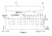
図6において、光走査の際、光ファイバ32が被検者H側に所定角度傾けて配置され、出射端面33は被検者H側に向いているので、番号1、2といった被検者H側の光ファイバ32の出射端面33から発せられた光は斜めに入射し、乳房C1だけでなくその奥の胸壁部分C2にも達する。このため、番号1、2の光によって発生した音響波は胸壁部分C2の情報を多く含んでおり、従って当然ながら音響波を画像化した光音響画像にも、乳房C1だけでなく胸壁部分C2の情報が含まれる。乳房C1を無理矢理引き出して圧迫板17で強く圧迫するようなことをしなくとも、乳がんの診断に必要とされる胸壁部分C2の情報も含んだ光音響画像を容易に得ることができる。 In FIG. 6, since the
全ての光ファイバ32を被検者H側に所定角度傾けるので、検出部30の構造をシンプルにすることができ、製造も簡単にすることができる。また、光の照射部位が重複しないので、光吸収による熱励起が過度になるおそれがなく、被検者Hへの負担が軽減される。 Since all the
第一実施形態では、全ての光ファイバ32を被検者H側に所定角度傾けているが、本発明はこれに限定されない。以下に示す第二、第三実施形態を採用してもよい。なお、第一実施形態と同一の部材には同一符号を付し、説明を省略する。 In the first embodiment, all the
[第二実施形態]
図7において、本実施形態の検出部75は、被検者H側の2列の光ファイバ32のみを被検者H側に所定角度傾け、その他の光ファイバ32はZ方向に平行に立設し、乳房C1に対して垂直に向けている。この場合の光走査の順番は、矢印上の番号で示すように、所定角度傾けた光ファイバ32の列から先に行う。[Second Embodiment]
In FIG. 7, the
検出部75の断面図を示す図8において、所定角度傾けた光走査が1番目、2番目の光ファイバ32と、Z方向に平行に立設された光走査の順番が3番目、4番目の光ファイバ32とは、Y方向にずらして同じ開口34および貫通孔50にそれぞれ配置されている。保持プレート52には、所定角度傾けた光ファイバ32用の保持孔53の他に、Z方向に平行に立設された光ファイバ32用の保持孔76が形成されている。所定角度傾けた光ファイバ32とZ方向に平行に立設された光ファイバ32を別の開口34および貫通孔50に配置する場合に比べて、省スペース化および製造工程の簡略化を図ることができる。 In FIG. 8 showing a cross-sectional view of the
所定角度傾けた光ファイバ32とZ方向に平行に立設された光ファイバ32を同じ開口34および貫通孔50に近接配置すると、図7の番号2、3を付した矢印で示すように光の照射部位が重複する。この場合、光の照射部位が重複した領域に対しては、互いに重複する電気音響変換信号の単純平均をとるか、あるいは胸壁部分C2の情報を多く含む電気音響変換信号を優先的に重み付けした加重平均をとって光音響画像を生成することが好ましい。 When the
[第三実施形態]
図9において、本実施形態の検出部80は、cMUT31およびZ方向に平行に立設された光ファイバ32とは独立して、撮影台16の被検者Hに対向する側面81に、被検者H側に所定角度傾けた光ファイバ32を配置している。撮影台16の側面81には、光ファイバ32の出射端面33が覗く開口、および第4保護層46と同じ透明層が設けられている(ともに図示せず)。[Third embodiment]
In FIG. 9, the
cMUT31およびZ方向に平行に立設された光ファイバ32と独立して被検者H側に所定角度傾けた光ファイバ32を設けることにより、cMUT31およびZ方向に平行に立設された光ファイバ32の部分の構造をシンプルにすることができ、製造も簡単にすることができる。また、光の照射部位が重複しないので、第一実施形態と同様の効果が得られる。さらに、撮影台16の被検者Hに対向する側面81に被検者H側に所定角度傾けた光ファイバ32を配置するので、より胸壁部分C2に出射端面33を近付けることができ、比較的少ない光エネルギーで胸壁部分C2の情報を効率よく得ることができる。 By providing an
なお、第一実施形態と第三実施形態を複合し、全ての光ファイバ32を被検者H側に傾け、且つ側面81に光ファイバ32を配置してもよい。 The first embodiment may be combined with the third embodiment, and all the
cMUTの列と光ファイバの列とを別々のブロックにて作製し、各ブロックを交互に複数結合して検出部を作製してもよい。この場合、光ファイバのブロックにはシリコン基板や第一〜第三保護層はいらず、保持プレートのみでよい。 The cMUT column and the optical fiber column may be manufactured in separate blocks, and a plurality of blocks may be alternately coupled to manufacture the detection unit. In this case, the optical fiber block does not require the silicon substrate or the first to third protective layers, but only the holding plate.
上記各実施形態では、cMUTを音響波受信手段として用いているが、pMUT(Piezoelectric Micromachined Ultrasonic Transducer)でもよく、PZT等の圧電セラミックス厚膜やPVDF等の高分子圧電材料でも構わない。また、超音波トランスデューサに限らず、例えば磁歪素子を音響波の受信に用いてもよい。 In each of the above embodiments, the cMUT is used as the acoustic wave receiving means. However, a pMUT (Piezoelectric Micromachined Ultrasonic Transducer) may be used, and a piezoelectric ceramic thick film such as PZT or a polymer piezoelectric material such as PVDF may be used. In addition to the ultrasonic transducer, for example, a magnetostrictive element may be used for receiving acoustic waves.
cMUTおよび光ファイバの出射端面の配置、個数、配列ピッチ、光ファイバの傾き角度等は、装置の仕様に応じて適宜変更可能である。また、光走査の順番や音響波を受信するcMUTの選択の仕方も同様である。例えば、撮影台だけでなく圧迫板にも検出部を設け、乳房の両側から光走査および音響波の受信を行ってもよいし、光ファイバを1本単位で選択して光走査を行ってもよい。あるいは、被検者Hの体格や術者の好み等に応じて、被検者H側の光ファイバの傾き角度を所定範囲で変更可能なアクチュエータを設けてもよい。 The arrangement, the number, the arrangement pitch, the inclination angle of the optical fiber, and the like of the emission end faces of the cMUT and the optical fiber can be appropriately changed according to the specifications of the apparatus. The same applies to the order of optical scanning and the method of selecting a cMUT that receives acoustic waves. For example, the detection unit may be provided not only on the imaging table but also on the compression plate, and optical scanning and acoustic wave reception may be performed from both sides of the breast, or optical scanning may be performed by selecting an optical fiber as a unit. Good. Alternatively, an actuator that can change the inclination angle of the optical fiber on the subject H side within a predetermined range may be provided in accordance with the physique of the subject H, the operator's preference, and the like.
2 光音響式乳房画像撮影装置
10 撮影スタンド
11 プロセッサ部
16 撮影台
21 載置面
30、75、80 検出部
31 容量検出型超音波トランスデューサ(cMUT)
32 光ファイバ
33 出射端面
60 主制御部
64 画像処理部
68 走査制御部
69 受信部
81 側面2
32 Optical fiber 33
Claims (6)
Translated fromJapanese光の照射により発生する音響波を受信する複数の音響波受信手段とが被検者の乳房が載置される撮影台に設けられ、
前記複数の光照射手段は、乳房の載置範囲外にある被検者の胸壁部分に向けて光が照射されるよう配置されていることを特徴とする光音響式乳房画像撮影装置。A plurality of light irradiation means for irradiating light;
A plurality of acoustic wave receiving means for receiving acoustic waves generated by light irradiation are provided on an imaging table on which a subject's breast is placed,
The photoacoustic breast imaging apparatus characterized in that the plurality of light irradiation means are arranged so that light is irradiated toward a chest wall portion of a subject outside the placement range of the breast.
撮影台の被検者と対向する面に取り付けた光照射手段の出射面を被検者側に向けることを特徴とする請求項1ないし4のいずれかに記載の光音響式乳房画像撮影装置。Attaching substantially all of the plurality of light irradiation means to the breast mounting surface of the imaging table, and attaching the rest of the plurality of light irradiation means to the surface facing the subject of the imaging table, respectively.
5. The photoacoustic mammography apparatus according to any one of claims 1 to 4, wherein an exit surface of light irradiation means attached to a surface of the imaging table facing the subject is directed toward the subject.
Priority Applications (2)
| Application Number | Priority Date | Filing Date | Title |
|---|---|---|---|
| JP2010053503AJP2011183057A (en) | 2010-03-10 | 2010-03-10 | Photoacoustic mammography apparatus |
| US13/016,350US20110224532A1 (en) | 2010-03-10 | 2011-01-28 | Photoacoustic breast-image capturing apparatus |
Applications Claiming Priority (1)
| Application Number | Priority Date | Filing Date | Title |
|---|---|---|---|
| JP2010053503AJP2011183057A (en) | 2010-03-10 | 2010-03-10 | Photoacoustic mammography apparatus |
Publications (1)
| Publication Number | Publication Date |
|---|---|
| JP2011183057Atrue JP2011183057A (en) | 2011-09-22 |
Family
ID=44560615
Family Applications (1)
| Application Number | Title | Priority Date | Filing Date |
|---|---|---|---|
| JP2010053503AWithdrawnJP2011183057A (en) | 2010-03-10 | 2010-03-10 | Photoacoustic mammography apparatus |
Country Status (2)
| Country | Link |
|---|---|
| US (1) | US20110224532A1 (en) |
| JP (1) | JP2011183057A (en) |
Cited By (8)
| Publication number | Priority date | Publication date | Assignee | Title |
|---|---|---|---|---|
| JP2013158531A (en)* | 2012-02-07 | 2013-08-19 | Canon Inc | Apparatus and method for obtaining subject information |
| JP2013215262A (en)* | 2012-04-05 | 2013-10-24 | Canon Inc | Subject information acquiring apparatus |
| JP2014200447A (en)* | 2013-04-04 | 2014-10-27 | キヤノン株式会社 | Subject information acquisition apparatus and method of controlling the same |
| KR20150058714A (en)* | 2013-11-20 | 2015-05-29 | 삼성전자주식회사 | Breast scanning apparatus using photoacoustic ultrasonic wave |
| EP2921103A1 (en) | 2014-03-19 | 2015-09-23 | Canon Kabushiki Kaisha | Object information acquiring apparatus |
| KR20160142454A (en) | 2015-06-02 | 2016-12-13 | 고려대학교 산학협력단 | Optoacoustic imaging system and stage of the same |
| US20170311924A1 (en)* | 2014-10-23 | 2017-11-02 | Koninklijke Philips N.V. | Shape sensing for flexible ultrasound trasnducers |
| WO2018101258A1 (en) | 2016-11-30 | 2018-06-07 | Canon Kabushiki Kaisha | Display control apparatus, display method, and program |
Families Citing this family (11)
| Publication number | Priority date | Publication date | Assignee | Title |
|---|---|---|---|---|
| JP5553672B2 (en)* | 2010-04-26 | 2014-07-16 | キヤノン株式会社 | Acoustic wave measuring apparatus and acoustic wave measuring method |
| US9289191B2 (en) | 2011-10-12 | 2016-03-22 | Seno Medical Instruments, Inc. | System and method for acquiring optoacoustic data and producing parametric maps thereof |
| US8686335B2 (en) | 2011-12-31 | 2014-04-01 | Seno Medical Instruments, Inc. | System and method for adjusting the light output of an optoacoustic imaging system |
| WO2013067374A1 (en)* | 2011-11-02 | 2013-05-10 | Seno Medical Instruments, Inc. | System and method for dynamically varying the angle of light transmission in an optoacoustic imaging system |
| TWM458203U (en)* | 2012-12-17 | 2013-08-01 | Ind Tech Res Inst | Photoacoustic detector, photoacoustic board and dector using the photoacoustic board |
| JP6091259B2 (en)* | 2013-03-05 | 2017-03-08 | キヤノン株式会社 | SUBJECT INFORMATION ACQUISITION DEVICE AND METHOD FOR CONTROLLING SUBJECT INFORMATION ACQUISITION DEVICE |
| KR101511085B1 (en) | 2013-11-01 | 2015-04-14 | 삼성메디슨 주식회사 | Photoacoustic apparatus and operating method for the same |
| US20150150462A1 (en)* | 2013-12-03 | 2015-06-04 | General Electric Company | System and method for low cost photoacoustic imaging |
| JP6049209B2 (en)* | 2014-01-28 | 2016-12-21 | 富士フイルム株式会社 | Photoacoustic measurement probe and photoacoustic measurement apparatus including the same |
| CN104825180A (en)* | 2015-04-23 | 2015-08-12 | 北京大学 | Tri-modal breast imaging system and imaging method thereof |
| WO2024144684A2 (en)* | 2022-12-26 | 2024-07-04 | Bilkent Universitesi Ulusal Nanoteknoloji Arastirma Merkezi | A compact photoacoustic probe and production method thereof |
Family Cites Families (5)
| Publication number | Priority date | Publication date | Assignee | Title |
|---|---|---|---|---|
| US4419585A (en)* | 1981-02-26 | 1983-12-06 | Massachusetts General Hospital | Variable angle slant hole collimator |
| US4817623A (en)* | 1983-10-14 | 1989-04-04 | Somanetics Corporation | Method and apparatus for interpreting optical response data |
| CN101031244A (en)* | 2004-09-29 | 2007-09-05 | 皇家飞利浦电子股份有限公司 | Methods and apparatus for performing enhanced ultrasound diagnostic breast imaging |
| EP1940515A4 (en)* | 2005-09-06 | 2010-05-26 | Resonant Medical Inc | System and method for patient setup for radiotherapy treatment |
| US20100104505A1 (en)* | 2006-12-11 | 2010-04-29 | O'connor Michael K | System and Method for Quantitative Molecular Breast Imaging |
- 2010
- 2010-03-10JPJP2010053503Apatent/JP2011183057A/ennot_activeWithdrawn
- 2011
- 2011-01-28USUS13/016,350patent/US20110224532A1/ennot_activeAbandoned
Cited By (13)
| Publication number | Priority date | Publication date | Assignee | Title |
|---|---|---|---|---|
| JP2013158531A (en)* | 2012-02-07 | 2013-08-19 | Canon Inc | Apparatus and method for obtaining subject information |
| JP2013215262A (en)* | 2012-04-05 | 2013-10-24 | Canon Inc | Subject information acquiring apparatus |
| JP2014200447A (en)* | 2013-04-04 | 2014-10-27 | キヤノン株式会社 | Subject information acquisition apparatus and method of controlling the same |
| KR20150058714A (en)* | 2013-11-20 | 2015-05-29 | 삼성전자주식회사 | Breast scanning apparatus using photoacoustic ultrasonic wave |
| KR102189676B1 (en) | 2013-11-20 | 2020-12-14 | 삼성전자주식회사 | Breast scanning apparatus using photoacoustic ultrasonic wave |
| US10571330B2 (en) | 2014-03-19 | 2020-02-25 | Canon Kabushiki Kaisha | Object information acquiring apparatus |
| US9857215B2 (en) | 2014-03-19 | 2018-01-02 | Canon Kabushiki Kaisha | Object information acquiring apparatus |
| EP2921103A1 (en) | 2014-03-19 | 2015-09-23 | Canon Kabushiki Kaisha | Object information acquiring apparatus |
| US20170311924A1 (en)* | 2014-10-23 | 2017-11-02 | Koninklijke Philips N.V. | Shape sensing for flexible ultrasound trasnducers |
| US10682119B2 (en)* | 2014-10-23 | 2020-06-16 | Koninklijke Philips N.V. | Shape sensing for flexible ultrasound transducers |
| KR20160142454A (en) | 2015-06-02 | 2016-12-13 | 고려대학교 산학협력단 | Optoacoustic imaging system and stage of the same |
| WO2018101258A1 (en) | 2016-11-30 | 2018-06-07 | Canon Kabushiki Kaisha | Display control apparatus, display method, and program |
| US11599992B2 (en) | 2016-11-30 | 2023-03-07 | Canon Kabushiki Kaisha | Display control apparatus, display method, and non-transitory storage medium |
Also Published As
| Publication number | Publication date |
|---|---|
| US20110224532A1 (en) | 2011-09-15 |
Similar Documents
| Publication | Publication Date | Title |
|---|---|---|
| JP2011183057A (en) | Photoacoustic mammography apparatus | |
| JP5448918B2 (en) | Biological information processing device | |
| CN103784161B (en) | The control method of ultrasonic measurement device and ultrasonic measurement device | |
| JP5210080B2 (en) | Medical imaging device | |
| JP5337782B2 (en) | Ultrasonic diagnostic equipment | |
| JP5435751B2 (en) | Ultrasonic diagnostic apparatus, ultrasonic transmission / reception method, and ultrasonic transmission / reception program | |
| JP5950540B2 (en) | SUBJECT INFORMATION ACQUISITION DEVICE, CONTROL METHOD FOR THE DEVICE, AND PROGRAM | |
| JP2015202400A (en) | Ultrasonic probe, ultrasonic imaging apparatus, and method of controlling the same | |
| JP2009082402A (en) | MEDICAL IMAGE DIAGNOSTIC SYSTEM, MEDICAL IMAGING DEVICE, MEDICAL IMAGE STORAGE DEVICE, AND MEDICAL IMAGE DISPLAY DEVICE | |
| KR20160069293A (en) | Probe, Ultrasound Imaging Apparatus, and Controlling Method of the Ultrasound Imaging Apparatus | |
| JP6334992B2 (en) | Portable ultrasonic diagnostic equipment | |
| KR102185362B1 (en) | Ultrasonic probe and medical apparatus including the same | |
| JP5843570B2 (en) | SUBJECT INFORMATION ACQUISITION DEVICE, CONTROL METHOD FOR THE DEVICE, AND PROGRAM | |
| JP2013102805A (en) | Object information acquiring apparatus and control method thereof | |
| JP2013226335A (en) | Acoustic wave diagnosis device and image display method | |
| JP2025114763A (en) | Ultrasound diagnostic device and display method for ultrasound diagnostic device | |
| JP2009082449A (en) | Medical imaging device | |
| KR20150020945A (en) | Acoustic probe and Method for manufacturing the same | |
| JP5226360B2 (en) | Ultrasonic diagnostic equipment | |
| JP2010233896A (en) | Ultrasonic diagnostic equipment | |
| JP2011143078A (en) | Ultrasonograph | |
| JP5254390B2 (en) | Ultrasonic diagnostic apparatus and ultrasonic image generation method | |
| JP2007159651A (en) | Ultrasonic probe and ultrasonic diagnostic apparatus | |
| KR20110003056A (en) | Ultrasonic Probes and Ultrasonic Diagnostics | |
| JP2021000275A (en) | Medical image photographing system |
Legal Events
| Date | Code | Title | Description |
|---|---|---|---|
| A621 | Written request for application examination | Free format text:JAPANESE INTERMEDIATE CODE: A621 Effective date:20120703 | |
| A761 | Written withdrawal of application | Free format text:JAPANESE INTERMEDIATE CODE: A761 Effective date:20130305 |