JP2011177407A - Fluid injection device - Google Patents
Fluid injection deviceDownload PDFInfo
- Publication number
- JP2011177407A JP2011177407AJP2010046299AJP2010046299AJP2011177407AJP 2011177407 AJP2011177407 AJP 2011177407AJP 2010046299 AJP2010046299 AJP 2010046299AJP 2010046299 AJP2010046299 AJP 2010046299AJP 2011177407 AJP2011177407 AJP 2011177407A
- Authority
- JP
- Japan
- Prior art keywords
- suction
- tube
- injection
- opening
- pipe
- Prior art date
- Legal status (The legal status is an assumption and is not a legal conclusion. Google has not performed a legal analysis and makes no representation as to the accuracy of the status listed.)
- Withdrawn
Links
Images


Classifications
- A—HUMAN NECESSITIES
- A61—MEDICAL OR VETERINARY SCIENCE; HYGIENE
- A61B—DIAGNOSIS; SURGERY; IDENTIFICATION
- A61B17/00—Surgical instruments, devices or methods
- A61B17/32—Surgical cutting instruments
- A61B17/3203—Fluid jet cutting instruments
- B—PERFORMING OPERATIONS; TRANSPORTING
- B05—SPRAYING OR ATOMISING IN GENERAL; APPLYING FLUENT MATERIALS TO SURFACES, IN GENERAL
- B05B—SPRAYING APPARATUS; ATOMISING APPARATUS; NOZZLES
- B05B1/00—Nozzles, spray heads or other outlets, with or without auxiliary devices such as valves, heating means
- B05B1/02—Nozzles, spray heads or other outlets, with or without auxiliary devices such as valves, heating means designed to produce a jet, spray, or other discharge of particular shape or nature, e.g. in single drops, or having an outlet of particular shape
- B05B1/08—Nozzles, spray heads or other outlets, with or without auxiliary devices such as valves, heating means designed to produce a jet, spray, or other discharge of particular shape or nature, e.g. in single drops, or having an outlet of particular shape of pulsating nature, e.g. delivering liquid in successive separate quantities
- B—PERFORMING OPERATIONS; TRANSPORTING
- B05—SPRAYING OR ATOMISING IN GENERAL; APPLYING FLUENT MATERIALS TO SURFACES, IN GENERAL
- B05B—SPRAYING APPARATUS; ATOMISING APPARATUS; NOZZLES
- B05B14/00—Arrangements for collecting, re-using or eliminating excess spraying material
- B05B14/30—Arrangements for collecting, re-using or eliminating excess spraying material comprising enclosures close to, or in contact with, the object to be sprayed and surrounding or confining the discharged spray or jet but not the object to be sprayed
- A—HUMAN NECESSITIES
- A61—MEDICAL OR VETERINARY SCIENCE; HYGIENE
- A61B—DIAGNOSIS; SURGERY; IDENTIFICATION
- A61B17/00—Surgical instruments, devices or methods
- A61B2017/00535—Surgical instruments, devices or methods pneumatically or hydraulically operated
- A61B2017/00539—Surgical instruments, devices or methods pneumatically or hydraulically operated hydraulically
- A—HUMAN NECESSITIES
- A61—MEDICAL OR VETERINARY SCIENCE; HYGIENE
- A61B—DIAGNOSIS; SURGERY; IDENTIFICATION
- A61B2217/00—General characteristics of surgical instruments
- A61B2217/002—Auxiliary appliance
- A61B2217/005—Auxiliary appliance with suction drainage system
Landscapes
- Health & Medical Sciences (AREA)
- Life Sciences & Earth Sciences (AREA)
- Surgery (AREA)
- Heart & Thoracic Surgery (AREA)
- Engineering & Computer Science (AREA)
- Biomedical Technology (AREA)
- Nuclear Medicine, Radiotherapy & Molecular Imaging (AREA)
- Medical Informatics (AREA)
- Molecular Biology (AREA)
- Animal Behavior & Ethology (AREA)
- General Health & Medical Sciences (AREA)
- Public Health (AREA)
- Veterinary Medicine (AREA)
- Surgical Instruments (AREA)
- Nozzles (AREA)
Abstract
Description
Translated fromJapanese本発明は、噴射管と吸引管とを有する流体噴射装置に関する。 The present invention relates to a fluid ejection device having an ejection tube and a suction tube.
流体噴射装置を用いて生体組織の切除・切開・破砕する方法は、熱損傷がなく、血管等の細管組織を温存できるなど手術具として優れた特性を有している。このような流体噴射装置を用いて手術等を行う場合、噴射された液体や切除組織等が術部に溜り視野が確保できないことがある。そのために液体や切除組織を吸引除去するための吸引管を併設するものがある。 A method of excising, incising, and crushing a living tissue using a fluid ejecting apparatus has excellent characteristics as a surgical tool, such as being free from thermal damage and capable of preserving tubule tissue such as blood vessels. When an operation or the like is performed using such a fluid ejecting apparatus, the ejected liquid or ablated tissue may accumulate in the surgical site and a visual field may not be secured. For this purpose, there are some which are provided with a suction tube for sucking and removing liquid and excised tissue.
このような流体噴射装置の1例としては、高圧流体を噴射する噴射管を、吸引管の吸引流路内に、吸引流路に対して同心となるように配設したものが提案されている(例えば、特許文献1参照)。 As an example of such a fluid ejecting apparatus, an apparatus in which an ejecting pipe for ejecting high-pressure fluid is arranged in a suction channel of the suction pipe so as to be concentric with the suction channel. (For example, refer to Patent Document 1).
また、他の例としては、高圧流体を噴射させる噴射管を、吸引管の内周面に対して偏心させた状態で内挿させた流体噴射装置が提案されている(例えば、特許文献2参照)。 As another example, there has been proposed a fluid ejecting apparatus in which an ejection pipe for ejecting high-pressure fluid is inserted in a state of being eccentric with respect to an inner peripheral surface of a suction pipe (see, for example, Patent Document 2). ).
また、流体室の容積を容積変更手段により急激に変化させ流体を脈流に変換して噴射開口部からパルス状に高速噴射させる流体噴射装置がある(例えば、特許文献3参照)。 Further, there is a fluid ejecting apparatus that rapidly changes the volume of a fluid chamber by volume changing means to convert the fluid into a pulsating flow and ejects the fluid at high speed in a pulsed manner from an ejection opening (for example, see Patent Document 3).
上述した特許文献1では、吸引管の内周面と噴射管の外周面とが同心となるように配設されているため、吸引開口部の吸引流路の大きさ(吸引管の内周面と噴射管の外周面との隙間寸法)は、吸引管の内径と噴射管の外径との差の1/2となり、この大きさよりも大きな切除組織は吸引除去することは困難である。また、吸引流路の大きさを確保するために吸引管の径を大きくすると術視野が狭まってしまうという課題がある。 In Patent Document 1 described above, since the inner peripheral surface of the suction tube and the outer peripheral surface of the injection tube are arranged concentrically, the size of the suction flow path of the suction opening (the inner peripheral surface of the suction tube) And the outer peripheral surface of the injection tube) is 1/2 of the difference between the inner diameter of the suction tube and the outer diameter of the injection tube, and it is difficult to suck and remove excised tissue larger than this size. In addition, if the diameter of the suction tube is increased in order to ensure the size of the suction channel, there is a problem that the surgical field of view is narrowed.
また、特許文献2では、噴射管が吸引管の内周面に偏心された状態で内挿されていることから、吸引流路の大きさは、吸引管の内径と噴射管の外径との差となり、特許文献1と同じ直径の吸引管と噴射管を用いる場合に、同心の場合よりも大きくなる。しかしながら、高圧流体を噴射させる場合、噴射管の先端、つまり噴射開口部付近に振動が発生することがあり、狙いの術部に流体を噴射することが困難となる。 Moreover, in
また、特許文献2のように、噴射管を吸引管に偏心させて内挿する構成では、噴射開口部の位置を直接視認できないため、正確な術部位置に流体を噴射しにくいという課題もある。 In addition, as in
また、特許文献3による流体噴射装置は、上述した特許文献1または特許文献2の高圧流体を連続流で噴射させるものより少ない流量で切除が可能であるが、術部の視認性を向上させるため、あるいは切除組織の吸引除去のために吸引管を設けることが求められる場合がある。このような場合、吸引流路を大きくするために、特許文献2のように噴射管を吸引管の内周面に対して偏心させた状態で内挿させる構造を採用することが可能である。しかし、流体をパルス状に噴射させる場合には、噴射管の振動は連続流噴射のものより大きくなることが予測される。 In addition, the fluid ejecting apparatus according to Patent Document 3 can be excised with a smaller flow rate than that of the above-described Patent Document 1 or
このように、噴射管に振動が発生した場合には、噴射管と吸引管とが当って異常な音が発生することや、噴射管の先端(噴射開口部)の振動により吸引管が共振して術部位置に流体を噴射させることが困難となる。 In this way, when vibration occurs in the injection tube, the injection tube and the suction tube come into contact with each other and abnormal noise is generated, or the suction tube resonates due to vibration of the tip (injection opening) of the injection tube. This makes it difficult to eject fluid to the surgical site position.
本発明は、上述の課題の少なくとも一部を解決するためになされたものであり、以下の形態または適用例として実現することが可能である。 SUMMARY An advantage of some aspects of the invention is to solve at least a part of the problems described above, and the invention can be implemented as the following forms or application examples.
[適用例1]本適用例に係る流体噴射装置は、流体を脈流に変換する脈流発生部と、前記脈流発生部に突設される吸引管と、前記吸引管に、前記吸引管の内周面に外周面が接触するよう偏心して内挿され、前記脈流発生部に連通する噴射開口部を有する噴射管と、前記吸引管の内周面と前記噴射管の外周面との間に形成される吸引流路と吸引開口部と、を有し、前記噴射管が前記噴射開口部の近傍で前記吸引管の内周面に固定されていることを特徴とする。 Application Example 1 A fluid ejecting apparatus according to this application example includes a pulsating flow generation unit that converts a fluid into a pulsating flow, a suction pipe that protrudes from the pulsating flow generation unit, the suction pipe, and the suction pipe An injection tube having an injection opening that is eccentrically inserted so that the outer peripheral surface is in contact with the inner peripheral surface, and communicates with the pulsating flow generation unit, and an inner peripheral surface of the suction tube and an outer peripheral surface of the injection tube It has a suction flow path and a suction opening formed between, and the injection pipe is fixed to the inner peripheral surface of the suction pipe in the vicinity of the injection opening.
本適用例によれば、噴射管が吸引管に偏心された状態で内挿されていることから、吸引流路の大きさは、吸引管の内径と噴射管の外径との差となる。例えば、吸引管の内径をd1、噴射管の外径をd2とすれば、吸引流路の大きさ(隙間寸法)はd1−d2となり、吸引管と噴射管とを同心とする場合の吸引流路の大きさは(d1−d2)/2となる。よって、偏心させた場合の吸引流路の大きさは、同心にする場合の吸引流路の大きさよりも大きくなる。従って、噴射管と吸引管とを偏心させた場合には同心の場合よりも大きな切除組織を吸引することができ、噴射された排液の除去量も多くなり、良好な術視野が得られる。 According to this application example, since the injection tube is inserted in a state of being eccentric to the suction tube, the size of the suction channel is a difference between the inner diameter of the suction tube and the outer diameter of the injection tube. For example, if the inner diameter of the suction pipe is d1, and the outer diameter of the injection pipe is d2, the suction flow path size (gap size) is d1-d2, and the suction flow when the suction pipe and the injection pipe are concentric. The size of the road is (d1-d2) / 2. Therefore, the size of the suction channel when eccentric is larger than the size of the suction channel when concentric. Therefore, when the ejection tube and the suction tube are eccentric, a larger excised tissue can be aspirated than when the ejection tube and the suction tube are concentric, the amount of ejected drainage is increased, and a good surgical field is obtained.
また、噴射管を、噴射開口部の付近で吸引管の内周面に固定していることから噴射管の先端部の振動を抑制し、噴射管と吸引管とが当って異常な音が発生することを防止し、振動により噴射管の先端(噴射開口部)が動くことがなく、また、この振動により吸引管が共振することを抑制し、術部位置に正確に流体を噴射させることができるという効果がある。 In addition, since the injection tube is fixed to the inner peripheral surface of the suction tube in the vicinity of the injection opening, vibration at the tip of the injection tube is suppressed, and abnormal noise is generated when the injection tube and the suction tube hit each other. The tip of the ejection tube (ejection opening) does not move due to vibration, and the vibration of the suction tube is prevented from resonating due to this vibration, so that fluid can be ejected accurately to the surgical site position. There is an effect that can be done.
[適用例2]上記適用例に係る流体噴射装置において、前記吸引管の前記吸引開口部の近傍に、前記噴射開口部の位置を表す目印が設けられていることが好ましい。 Application Example 2 In the fluid ejecting apparatus according to the application example described above, it is preferable that a mark indicating the position of the ejection opening is provided in the vicinity of the suction opening of the suction pipe.
このように、噴射管を吸引管に対して偏心させて内挿する構成でも、噴射開口部の位置を示す目印を設けることにより、噴射開口部の位置を術者が認識できるので、術部位置に対して正確に流体を噴射することができる。 Thus, even in the configuration in which the ejection tube is eccentrically inserted with respect to the suction tube, the operator can recognize the position of the ejection opening by providing a mark indicating the position of the ejection opening. In contrast, the fluid can be ejected accurately.
[適用例3]上記適用例に係る流体噴射装置において、前記目印が、前記吸引開口部の周縁にかけて形成される切欠き部、または前記吸引開口部の近傍に開設される貫通孔であることが望ましい。 Application Example 3 In the fluid ejecting apparatus according to the application example described above, the mark may be a notch formed around a periphery of the suction opening or a through hole opened in the vicinity of the suction opening. desirable.
目印としては、吸引開口部付近に噴射開口部の位置を示す刻印等のマーキングでもよいが、吸引開口部の周縁にかけて切欠き部を形成することで、噴射開口部の位置を認識するができ、また、吸引開口部をこの切欠き部の分だけ大きくすることができる。
貫通孔の場合には、先端部に加え、側面方向にある切除組織の吸引除去を行うことが可能となる。The mark may be a marking such as a marking indicating the position of the injection opening near the suction opening, but by forming a notch around the periphery of the suction opening, the position of the injection opening can be recognized, Further, the suction opening can be enlarged by the amount corresponding to the notch.
In the case of the through-hole, it becomes possible to perform suction removal of the excised tissue in the side surface direction in addition to the tip portion.
以下、本発明の実施形態について図面を参照して説明する。
なお、以下の説明で参照する図は、図示の便宜上、部材ないし部分の縦横の縮尺は実際のものとは異なる模式図である。
(実施形態1)Embodiments of the present invention will be described below with reference to the drawings.
Note that the drawings referred to in the following description are schematic views in which the vertical and horizontal scales of members or portions are different from actual ones for convenience of illustration.
(Embodiment 1)
図1は、実施形態1に係る手術具としての流体噴射装置を示す構成説明図である。よって、以下で説明する流体は生理食塩水である。図1において、流体噴射装置1は、流体を収容する流体供給容器2と、流体供給手段としての供給ポンプ10と、供給ポンプ10から供給される流体を脈流(以降、パルス流と表すことがある)に変換させる脈流発生部20と、脈流発生部20に連通する噴射管70と、脈流発生部20に突設される吸引管80と、吸引手段としての吸引ポンプ11と、吸引された排液や切除組織を収容する排液容器3と、から構成されている。脈流発生部20と供給ポンプ10と流体供給容器2とは流体供給チューブ4によって接続されている。また、吸引管80と吸引ポンプ11と排液容器3とは吸引チューブ5によって接続されている。 FIG. 1 is a configuration explanatory view showing a fluid ejecting apparatus as a surgical instrument according to the first embodiment. Therefore, the fluid described below is physiological saline. In FIG. 1, a fluid ejecting apparatus 1 includes a
なお、脈流発生部としては、圧電素子を用いたピエゾ方式や、バブルジェット(登録商標)方式等、流体を脈流に変換してパルス状に噴射させることが可能な方式であれば適合可能であるが、以下に説明する脈流発生部はピエゾ方式を例示して説明する。 The pulsating flow generator can be adapted to any method that can convert fluid into pulsating flow and jet it in a pulsed manner, such as a piezo method using a piezoelectric element or a bubble jet (registered trademark) method. However, the pulsating flow generation unit described below will be described by exemplifying a piezo method.
噴射管70は、脈流発生部20の内部に形成される流体室60に連通する噴射流路71を有し、先端部には流路が縮小された噴射開口部72が開口されている。 The
噴射管70は、吸引管80の内周面に外周面が接触するように偏心して吸引管80に内挿されている。そして、噴射管70は、噴射開口部72の付近で吸引管80の内周面に接着等の固定手段により固定されている。吸引管80の内周面と噴射管70の外周面との間に形成される隙間が吸引流路81であり、吸引開口部82である。なお、噴射管70は、流体噴射時において変形しない程度の剛性を有し、吸引管80は噴射管70よりも剛性が高いことが望ましい。 The
次に、このように構成された流体噴射装置1における流体の流動を簡単に説明する。流体供給容器2に収容された流体は、供給ポンプ10によって吸引され、一定の圧力で流体供給チューブ4を介して脈流発生部20に供給される。脈流発生部20には、流体室60と、この流体室60の容積を変化させる容積変更手段としての圧電素子30とダイアフラム40と、が備えられており、圧電素子30を駆動して流体室60内において脈流を発生させ、噴射流路71を通って噴射開口部72から流体をパルス状に高速噴射する。 Next, the flow of fluid in the fluid ejecting apparatus 1 configured as described above will be briefly described. The fluid stored in the
なお、脈流発生部20が駆動を停止している場合、つまり、流体室60の容積を変更させないときには、供給ポンプ10から一定の圧力で供給された流体は流体室60を通って、噴射開口部72から連続流噴射される。 When the pulsating
ここで脈流とは、流体の流れる方向が一定で、流体の流量または流速が周期的または不定期な変動を伴った流体の流動を意味する。脈流には、流体の流動と停止とを繰り返す間欠流も含むが、流体の流量または流速が周期的または不定期な変動をしていればよいため、必ずしも間欠流である必要はない。 Here, the pulsating flow means a fluid flow in which the fluid flow direction is constant and the fluid flow rate or flow velocity is accompanied by periodic or irregular fluctuations. The pulsating flow includes an intermittent flow in which the flow and stop of the fluid are repeated. However, since the flow rate or flow velocity of the fluid only needs to fluctuate periodically or irregularly, the pulsating flow is not necessarily an intermittent flow.
同様に、流体をパルス状に噴射するとは、噴射する流体の流量または移動速度が周期的または不定期に変動した流体の噴射を意味する。パルス状の噴射の一例として、流体の噴射と非噴射とを繰り返す間欠噴射が挙げられるが、噴射する流体の流量または移動速度が周期的または不定期に変動していればよいため、必ずしも間欠噴射である必要はない。 Similarly, ejecting fluid in pulses means ejecting fluid in which the flow rate or movement speed of the fluid to be ejected varies periodically or irregularly. An example of pulsed injection is intermittent injection in which fluid injection and non-injection are repeated. However, since the flow rate or moving speed of the fluid to be injected only needs to fluctuate periodically or irregularly, it is not always intermittent injection. Need not be.
次に、吸引について説明する。噴射開口部72から噴射された流体は、術部において排液として滞留する。また、術部には切除された生体組織が存在する。これら排液や切除組織は、吸引ポンプ11によって吸引され、吸引開口部82から吸引流路81及び吸引チューブ5を介して排液容器3に収容される。吸引ポンプ11の駆動は、脈流発生部20の駆動に連動させてもよく、定期的に間歇駆動させてもよい。 Next, suction will be described. The fluid ejected from the ejection opening 72 stays as drainage at the surgical site. In addition, resected living tissue exists in the surgical site. These drainage and excised tissue are sucked by the
なお、噴射管70及び吸引管80の形状及び構造は、いくつか複数通りのものが考えられる。そこで、それらを具体的な実施例として図面を参照して説明する。
(第1実施例)Note that several shapes and structures of the
(First embodiment)
まず、第1実施例について説明する。
図2は、第1実施例に係る脈流発生部、噴射管及び吸引管を流体の噴射方向に沿って切断した切断面を示す断面図である。脈流発生部20は、供給ポンプ10から流体供給チューブ4を介して流体室60に流体を供給する入口流路61と、流体室60の容積を変化させる容積変更手段としての圧電素子30及びダイアフラム40と、流体室60に連通する出口流路62と、を有して構成されている。First, the first embodiment will be described.
FIG. 2 is a cross-sectional view illustrating a cut surface obtained by cutting the pulsating flow generation unit, the ejection pipe, and the suction pipe according to the first embodiment along the fluid ejection direction. The pulsating
ダイアフラム40は、円盤状の金属薄板からなり、下ケース50と上ケース52によって密着固定されている。圧電素子30は、本実施形態では積層型圧電素子を例示しており、両端部の一方が上板35を介してダイアフラム40に、他方が底板51に固着されている。 The
流体室60は、上ケース52のダイアフラム40に対向する面に形成される凹部とダイアフラム40とによって形成される空間である。流体室60の略中央部には出口流路62が開口されている。 The
上ケース52と下ケース50とは、それぞれ対向する面において接合一体化されている(図2ではダイアフラム40を介在させている)。上ケース52には、出口流路62に連通する噴射流路71を有する噴射管70が嵌着され、噴射管70の先端部には流路径が縮小された噴射開口部72が形成されている。なお、噴射開口部72をノズルで構成してもよい。 The
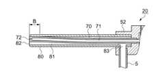
また、上ケース52には、噴射管70の外套管としての吸引管80が突設されている。吸引管80の脈流発生部20側の基端部付近には側壁を貫通する開口部83が開口され、吸引チューブ5がこの開口部83に連通するよう取り付けられている。なお、術者は脈流発生部20を把持して操作するため、吸引チューブ5の脈流発生部20付近の延在方向は、流体供給チューブ4と同じ方向にすることで、操作性を向上させることができる。 Further, the
図示するように、噴射管70は吸引管80に偏心した状態で内挿されている。よって、噴射管70の外周面と吸引管80の内周面とは、吸引管80の長さの範囲で接触するか、小さな隙間を有する関係にある。この状態について図3を参照して説明する。 As shown in the drawing, the
図3は、図2のA−A切断面を示す断面図であり、(a)は本実施例を示し、(b)は従来例を示している。(a)に示すように、噴射管70の外周面と吸引管80の内周面とは接触した状態である。このようにして形成される吸引管80の流路と噴射管70の外周面との隙間が吸引流路81であって、吸引管80の流路径をd1、噴射管70の外径をd2とすると、(d1−d2)が吸引流路81の最大大きさとなる。 3A and 3B are cross-sectional views showing the AA cross section of FIG. 2, wherein FIG. 3A shows the present embodiment, and FIG. 3B shows a conventional example. As shown to (a), the outer peripheral surface of the
ところで、特許文献1では、噴射管70が吸引管80に同心となるよう内挿されている。このような場合の吸引流路81の最大大きさは、(d1−d2)/2となり、吸引流路81の総面積は同じであっても、吸引流路81の大きさは偏心させた本実施例の方が大きくなる。なお、吸引開口部82の大きさも吸引流路81と同じ関係になる。 By the way, in Patent Document 1, the
本実施例では、吸引管80の内周面に噴射管70の外周面が接触する構造となっている。このような構造では、噴射管70を吸引管80に内挿して、吸引管80の内周面と噴射管70の外周面とを当接した状態で、接着剤等で固定しておき、上ケース52に圧入すれば組み込みが可能である。この際、図2に示すように噴射管70の上ケース52側基端部を吸引管80の基端部よりも突出させて上ケース52に圧入し、吸引管80は上ケース52とは遊勘の関係にして接着剤等で固定すればよい。なお、噴射管70及び吸引管80の上ケース52への固定には、接着剤、ロウ剤等でシーリング補強することが望ましい。 In this embodiment, the outer peripheral surface of the
なお、噴射管70と吸引管80との固定は、互いの長さ方向の接触範囲全体とすることが望ましいが、少なくとも噴射開口部72の先端付近(図2、図示Bの範囲)を固定すればよい。この場合は、上ケース52に噴射管70、吸引管80の順に挿着した後、図示Bの範囲を接着剤、ロウ剤等で接着固定するか、溶接等の固定手段を用いて固定すればよい。 The
また、吸引管80に設けられる開口部83及び吸引チューブ5の流路の大きさは、吸引開口部82の流路断面積と同じにするか、大きくすることが望ましい。 Further, it is desirable that the size of the flow path of the
次に、本実施例における脈流発生部20のパルス流噴射動作について図1、図2を参照して説明する。供給ポンプ10によって入口流路61には、一定の圧力で流体が供給されている。なお、供給ポンプ10からの流体供給量は噴射開口部72からのパルス流噴射量とほぼ等しい量であればよい。ここで、圧電素子30が動作を行わない場合、供給ポンプ10の吐出力と入口流路61側全体の流路抵抗の差によって流体は流体室60内に流動する。 Next, the pulse flow ejection operation of the pulsating
圧電素子30に駆動信号が入力され、圧電素子30がダイアフラム40の流体室60側の面に対して垂直方向に急激に伸長すると流体室60の容積が縮小され、流体室60内の圧力は、急速に上昇して数十気圧に達する。 When a drive signal is input to the
このとき、入口流路61から流体が流体室60へ流入する流量の減少量よりも、出口流路62から吐出される流体の増加量の方が大きいため噴射流路71に脈流が発生する。この吐出の際の圧力変動が噴射管70内を伝播して、先端の噴射開口部72からパルス化された流体が高速で噴射される。 At this time, since the increase amount of the fluid discharged from the
以上説明した第1実施例によれば、噴射管70が吸引管80に偏心された状態で内挿されていることから、吸引流路81及び吸引開口部82の大きさは、吸引管80の内径と噴射管70の外径との差となる。よって、偏心させた場合の吸引流路81及び吸引開口部82の大きさは、同心にする場合の大きさよりも大きくなる。従って、噴射管70と吸引管80とを偏心させた場合には、同心の場合よりも大きな切除組織を吸引することができ、噴射された排液の除去量も多くなり、良好な術視野が得られる。 According to the first embodiment described above, since the
また、噴射管70を、噴射開口部72の付近で吸引管80の内周面に固定していることからパルス流の噴射に起因する噴射管70の先端部が振動し、この振動により噴射管70と吸引管80とが当って異常な音が発生することを防止できる。また、噴射管70の先端(噴射開口部)が振動し、この振動により吸引管80が共振することを防止し、術部位置に正確に流体を噴射させることができる。 Further, since the
なお、本実施例では、吸引管80を上ケース52に固定する構造を例示したが、上ケース52を突出させて吸引管とすることも可能である。
また、吸引チューブ5の配設位置、延在方向は特に限定されないが、術者は脈流発生部20を把持して操作するので、脈流発生部20の近傍では、吸引チューブ5と流体供給チューブ4と互いに沿うように延在することで、操作するときのバランスがよくなり、操作性を向上させることができる。
(第2実施例)In the present embodiment, the structure in which the
Further, the arrangement position and the extending direction of the
(Second embodiment)
続いて、第2実施例について図面を参照して説明する。第2実施例は、前述した第1実施例が、噴射管70と吸引管80とを長さ全体に偏心させていることに対して、基端部を同心として先端部を偏心させていることを特徴としている。よって、第1実施例との相違箇所を中心に、第1実施例と同じ符号を付して説明する。 Next, a second embodiment will be described with reference to the drawings. In the second embodiment, the first embodiment described above has the
図4は、第2実施例に係る噴射管及び吸引管の構造を示す部分断面図である。吸引管80は基端部を上ケース52に圧入固定されている。また、噴射管70は吸引管80に対して同心となるよう基端部を上ケース52に圧入固定されている。そして、先端部(図示Bの範囲)において、噴射管70と吸引管80とを接着剤、ロウ剤等により接着固定、または溶接等の固定手段を用いて固定される。 FIG. 4 is a partial cross-sectional view showing the structure of the injection tube and the suction tube according to the second embodiment. The
このようにすれば、先端方向から視認した状態は、図3(a)と同じ状態となり、吸引開口部82の大きさは、同心の場合よりも大きくなる。従って、噴射管70と吸引管80の先端部を同心にする従来技術よりも大きな切除組織を吸引することができる。切除組織は、吸引開口部82において詰まりやすいことから、吸引開口部82を大きくしておくことで吸引能力を高めることができる。 If it does in this way, the state visually recognized from the front-end | tip direction will be the same state as Fig.3 (a), and the magnitude | size of the
また、噴射管70と吸引管80の基端部を同心にすれば、第1実施例のように偏心させて上ケース52に固定する構造よりも上ケース52の加工がしやすく、それぞれの圧入加工も容易になるという効果がある。 Further, if the proximal ends of the
なお、噴射管70を予め撓めておき、噴射管70の弾性力で吸引管80の内周面に付勢する構造としてもよい。この際、吸引管80の剛性を噴射管70の弾性力に耐える程度、及び振動を抑制可能な大きさにする。このようにすれば、先端部における固定加工はなくてもよい。
(第3実施例)The
(Third embodiment)
次に、第3実施例について図面を参照して説明する。第3実施例は、前述した第2実施例に対して、吸引管80と吸引チューブ5の接続位置が異なることに特徴を有する。よって、第2実施例との相違箇所を中心に、共通要素は第2実施例と同じ符号を付して説明する。 Next, a third embodiment will be described with reference to the drawings. The third embodiment is characterized in that the connection position of the
図5は、第3実施例に係る噴射管及び吸引管の構造を示す部分断面図である。噴射管70と吸引管80との関係は前述した第2実施例と同じである。第2実施例では、噴射管70と吸引管80とは、先端部において偏心させて固定されている。従って、固定部以外の吸引流路81は、基端部に向かって徐々に小さくなり、吸引チューブ5が設けられる開口部83近傍では、同心の場合と同じ大きさになる。よって、開口部83を吸引流路81が大きい範囲に設けることが望まれる。 FIG. 5 is a partial cross-sectional view showing the structure of the injection pipe and the suction pipe according to the third embodiment. The relationship between the
そこで、開口部位置Cを吸引流路81がより広い位置に設ける。このような場合は、接続流路91を有する管継ぎ手90を用いる。接続流路91は略L字状に曲げられ、吸引チューブ5は吸引管80に沿って延在され、さらに流体供給チューブ4(図2、参照)に沿って延在される。この際、吸引チューブ5を図示するように成形してもよく、吸引チューブが十分な弾性を有する場合には、図示D付近で結束バンド(図示せず)等により吸引管80に結束してもよい。 Therefore, the opening position C is provided at a position where the
このようにすれば、吸引流路81が同心の場合よりも大きい場所に開口部83を設けることで、吸引能力の低下を抑えることができる。また、このような構造にしても、吸引チューブ5の管継ぎ手90付近は吸引管80に沿って、脈流発生部20付近では流体供給チューブ4に沿って延在することで脈流発生部20を把持しやすくなり操作性を妨げない。
また、噴射管70及び吸引管80の基端部が取り付けられる上ケース52の構造を単純化することができる。
なお、管継ぎ手90と吸引管80とを一体で形成する構造としてもよく、管継ぎ手90と吸引チューブ5とを一体で成形してもよい。
(第4実施例)In this way, by providing the
Further, the structure of the
The pipe joint 90 and the
(Fourth embodiment)
次に、第4実施例について図面を参照して説明する。第4実施例は、前述した第3実施例に対して、噴射管70を基端部から先端部までの途中で曲げて、先端部で噴射管70と吸引管80とを固定することに特徴を有する。よって、第3実施例との相違箇所を中心に、共通要素は第3実施例と同じ符号を付して説明する。 Next, a fourth embodiment will be described with reference to the drawings. The fourth embodiment is characterized in that, with respect to the third embodiment described above, the
図6は、第4実施例に係る噴射管及び吸引管の構造を示す部分断面図である。噴射管70と吸引管80の上ケース52への取り付け構造は、前述した第2実施例及び第3実施例と同じで、互いに同心の関係にある。本実施例では、噴射管70が略中央付近で曲げられており、曲げ部70aより先端側は吸引管80の内周面に接触し、先端部(図示Bの範囲)で接着剤、ロウ剤等で接着固定、または溶接等の固定手段を用いて固定されている。曲げ部70aより基端部側は、吸引管80とほぼ同心となっている。 FIG. 6 is a partial cross-sectional view showing the structure of the injection pipe and the suction pipe according to the fourth embodiment. The attachment structure of the
吸引管80に設けられる開口部83(開口部位置C)は、曲げ部70aより先端側に配置され、管継ぎ手90により吸引チューブ5に連通される。吸引チューブ5は、流体供給チューブ4に沿って延在される。 An opening 83 (opening position C) provided in the
このようにすれば、吸引開口部82から曲げ部70aまでの吸引流路81が大きい位置に開口部83が設けられることで、吸引開口部82と略同じ大きさの吸引流路81を形成でき、同心の場合よりも大きい切除組織を吸引除去することができる。 In this way, by providing the
なお、曲げ部70aを基端部側に近づければ、吸引管80の開口部83を脈流発生部20に近づけることができ、脈流発生部20が把持しやすくなり、操作性を向上させることができる。また、曲げ部70aを上ケース52の範囲内に設ければ、第2実施例(図4、参照)と同様に、上ケース52に開口部83を設ける構造とすることができる。
(第5実施例)If the
(5th Example)
次に、第5実施例について図面を参照して説明する。第5実施例は、前述した第1実施例〜第4実施例の吸引管80が直線で形成されていることに対して、途中で曲げられていることに特徴を有している。流体噴射装置1を、腹腔手術等に用いる場合には、体表面の吸引管80の挿入位置に対して術部が直線上にないときがある。このような場合には、噴射管70及び吸引管80の先端部を基端部に対して曲げた位置にすることが要求される。本実施例は、そのような場合に対応する形態を有する。なお、第2実施例の構造をベースにして、第2実施例との共通機能要素には同じ符号を付して説明する。 Next, a fifth embodiment will be described with reference to the drawings. The fifth embodiment is characterized in that the
図7は、第5実施例に係る噴射管及び吸引管の構造を示す部分断面図である。吸引管80は、先端部と基端部と間の中間部において曲げられている。そして、噴射管70は、吸引管80の内周面に倣って曲げられ、噴射開口部72の付近(図示Bの範囲)で接着剤、ロウ剤等で接着、または溶接等の固定手段を用いて吸引管80の内周面に固定されている。 FIG. 7 is a partial cross-sectional view showing the structure of the injection pipe and the suction pipe according to the fifth embodiment. The
噴射管70を吸引管80の形状に倣って曲げ形成する方法も考えられるが、実際には、曲げられた管内に曲げられた管を挿入することは構造上困難である。そこで、ほぼ直線状の噴射管70を上ケース52に圧入固定した後に、吸引管80を噴射開口部72側から挿入していく。その際、噴射管70は、吸引管80の曲げ位置の斜面80aに噴射管70の先端部が当り、この斜面80a、曲げ部80bに倣って噴射管70が曲げられ、上ケース52に基端部が達したときに、図7に図示されるような形状となる。なお、腹腔手術の場合には、噴射管70及び吸引管80の長さは200mm〜400mm程度であるため、図示した状態よりも曲がり角度は緩やかになる。 A method of bending the
従って、本実施例によれば、手術部位、方法によって噴射管70及び吸引管80の先端部を基端部に対して曲げた位置にする場合においても、先端部において吸引管80と噴射管70とは偏心した状態であり、同心の場合に比べ吸引開口部82を大きくすることができる。なお、吸引流路81のうち曲げられた部分は、吸引開口部82よりも小さくなる位置があるが、噴射管70の外径が円形であるため、流路抵抗はごく小さく、切除組織の吸引の妨げになることはない。 Therefore, according to the present embodiment, even when the distal end portions of the
なお、本実施例では、噴射管70は、曲げられた吸引管80の内周面に倣って挿着されることから、先端部は吸引管80の内周面に噴射管70の弾性力で付勢される、よって、その付勢力が振動を抑制できる大きさであれば、必ずしも固定しなくてもよい。このことからも、吸引管80の剛性は、噴射管70の剛性よりも大きくしておく。
(第6実施例)In this embodiment, since the
(Sixth embodiment)
次に、第6実施例について図面を参照して説明する。第6実施例は、前述した第1実施例から第5実施例の流体噴射方向が、噴射流路71に対して直線上または平行であることに対して、噴射流路71に対して傾斜した方向に向いていることに特徴を有している。手術部位によっては、吸引管80の延在方向とはずれた位置の切除を行う場合がある。本実施例は、そのような場合に対応する形態を有する。なお、第1実施例の構造をベースにして、第1実施例との共通機能要素には同じ符号を付して説明する。 Next, a sixth embodiment will be described with reference to the drawings. The sixth embodiment is inclined with respect to the
図8は、第6実施例に係る噴射管及び吸引管の構造を示す部分断面図である。噴射管70及び吸引管80は、先端部において曲げられ、噴射管70は、吸引管80の曲げ部の内周面に倣っている。そして、噴射開口部72の付近で接着剤、ロウ剤等で固定、または溶接等の固定手段を用いて吸引管80の内周面に固定されている。 FIG. 8 is a partial cross-sectional view showing the structure of the injection pipe and the suction pipe according to the sixth embodiment. The
なお、吸引管80の流路径をd1とし、噴射管70の曲げ高さをhで表したとき、流路径d1は、h<d1の関係になるように設定する。このようにすることで、噴射管70を吸引管80に内挿することが可能となる。 In addition, when the flow path diameter of the
このようにすることによって、手術部位によって、吸引管80の延在方向とはずれた位置の切除と、切除組織の吸引排除を行うことができる。
なお、本実施例による構造は、前述した第1実施例〜第5実施例の各実施例にも適合可能である。
(第7実施例)By doing in this way, the excision of the excised tissue and the excision of the excised tissue can be performed depending on the surgical site.
Note that the structure according to the present embodiment can also be applied to each of the first to fifth embodiments described above.
(Seventh embodiment)
次に、第7実施例について図面を参照して説明する。前述した各実施例で説明したように、吸引開口部82に対して噴射開口部72が偏心した位置に配置されていることから、術者は噴射開口部を直接視認することは困難である。そこで、第7実施例は、吸引開口部82の近傍に、噴射開口部72の位置を表す目印が設けられていることを特徴とする。 Next, a seventh embodiment will be described with reference to the drawings. As described in each of the above-described embodiments, since the ejection opening 72 is disposed at an eccentric position with respect to the
図9は、第7実施例に係る噴射管及び吸引管の先端部を示し、(a)は断面図、(b)は先端方向(矢印E方向)から視認した正面図である。図9(a),(b)において、吸引管80の噴射開口部72の近傍には、目印としての切欠き部73が形成されている。切欠き部73は、吸引開口部82の周縁にかかる位置、形状に形成されており、術者は噴射管70の先端部(噴射開口部位置)を視認することが可能である。 9A and 9B show the distal end portions of the injection tube and the suction tube according to the seventh embodiment, where FIG. 9A is a cross-sectional view, and FIG. 9B is a front view viewed from the distal end direction (the direction of arrow E). 9A and 9B, a
目印としては、図示したような切欠きでもよいが、吸引管80の外周面に刻印、小孔または塗料等でマーキングしてもよい。しかし、本実施例による切欠き部73によれば、噴射開口部72の位置を術者が直接認識して操作することがきる。よって、正確な術部位置に流体を噴射し、切除することができる。
(第8実施例)The mark may be a notch as shown in the figure, but the outer peripheral surface of the
(Eighth embodiment)
次に、第8実施例について図面を参照して説明する。前述した第7実施例では、目印として1個の切欠き部73を設けていることに対して、吸引開口部に懸けて形成される切欠き、または吸引開口部の近傍に開設される貫通孔であることを特徴とする。 Next, an eighth embodiment will be described with reference to the drawings. In the seventh embodiment described above, a
図10は、第8実施例に係る吸引管の先端部を示す正面図である。図10において、吸引管80の先端部には吸引開口部82の周縁にかけて4つの切欠き部73a,73b,73c,73dが形成されている。図10の場合は、切欠き部73aが噴射開口部72の位置を示す目印である。そして他の切欠き部は、吸引開口部82の吸引機能を補完するために設けられる。従って、切欠き部73aは目印としての位置、形状を有しており、他の切欠き部73b〜73dは、切除組織の吸引可能な位置、形状を有している。なお、切欠き部73a〜73dは、吸引管80の先端部側面を貫通する貫通孔(図示せず)であってもよい。 FIG. 10 is a front view showing the distal end portion of the suction tube according to the eighth embodiment. In FIG. 10, four
従って、これら切欠き部73a〜73dを形成することによって、吸引開口部82付近に噴射開口部72の位置を示す目印とすることができる。また、これらの切欠き部を設けることにより、吸引開口部82の大きさをさらに補完することができ、切除組織の吸引除去能力を向上させることができる。 Therefore, by forming these
さらに、吸引開口部82の近傍に開設される貫通孔により、先端部の側面方向にある切除組織の吸引除去を行うことが可能となる。 Further, the through-hole formed in the vicinity of the
1…流体噴射装置、20…脈流発生部、70…噴射管、72…噴射開口部、80…吸引管、81…吸引流路、82…吸引開口部。 DESCRIPTION OF SYMBOLS 1 ... Fluid injection apparatus, 20 ... Pulse flow generation part, 70 ... Injection pipe, 72 ... Injection opening, 80 ... Suction pipe, 81 ... Suction flow path, 82 ... Suction opening
Claims (3)
Translated fromJapanese前記脈流発生部に突設される吸引管と、
前記吸引管に、前記吸引管の内周面に外周面が接触するよう偏心して内挿され、前記脈流発生部に連通する噴射開口部を有する噴射管と、
前記吸引管の内周面と前記噴射管の外周面との間に形成される吸引流路と吸引開口部と、
を有し、
前記噴射管が前記噴射開口部の近傍で前記吸引管の内周面に固定されていることを特徴とする流体噴射装置。A pulsating flow generating section that converts fluid into pulsating flow;
A suction pipe projecting from the pulsating flow generating section;
An injection pipe having an injection opening that is eccentrically inserted into the suction pipe so that an outer peripheral surface is in contact with an inner peripheral surface of the suction pipe and communicates with the pulsating flow generation section;
A suction flow path and a suction opening formed between the inner peripheral surface of the suction tube and the outer peripheral surface of the injection tube;
Have
The fluid ejecting apparatus according to claim 1, wherein the ejection pipe is fixed to an inner peripheral surface of the suction pipe in the vicinity of the ejection opening.
前記吸引管の前記吸引開口部の近傍に、前記噴射開口部の位置を表す目印が設けられていることを特徴とする流体噴射装置。The fluid ejection device according to claim 1,
A fluid ejecting apparatus, wherein a mark representing the position of the ejection opening is provided in the vicinity of the suction opening of the suction pipe.
前記目印が、前記吸引開口部の周縁にかけて形成される切欠き部、または前記吸引開口部の近傍に開設される貫通孔であることを特徴とする流体噴射装置。The fluid ejection device according to claim 2,
The fluid ejecting apparatus according to claim 1, wherein the mark is a notch formed around a periphery of the suction opening, or a through hole formed in the vicinity of the suction opening.
Priority Applications (6)
| Application Number | Priority Date | Filing Date | Title |
|---|---|---|---|
| JP2010046299AJP2011177407A (en) | 2010-03-03 | 2010-03-03 | Fluid injection device |
| CN201110048787.5ACN102188275B (en) | 2010-03-03 | 2011-03-01 | fluid ejection device |
| CN201510333338.3ACN105125258A (en) | 2010-03-03 | 2011-03-01 | FLUID INJECTION DEVICE and surgery apparatus |
| US13/039,042US8857734B2 (en) | 2010-03-03 | 2011-03-02 | Fluid injection device |
| US14/472,821US9358035B2 (en) | 2010-03-03 | 2014-08-29 | Fluid injection device |
| US15/147,815US20160242802A1 (en) | 2010-03-03 | 2016-05-05 | Fluid injection device |
Applications Claiming Priority (1)
| Application Number | Priority Date | Filing Date | Title |
|---|---|---|---|
| JP2010046299AJP2011177407A (en) | 2010-03-03 | 2010-03-03 | Fluid injection device |
Publications (1)
| Publication Number | Publication Date |
|---|---|
| JP2011177407Atrue JP2011177407A (en) | 2011-09-15 |
Family
ID=44530463
Family Applications (1)
| Application Number | Title | Priority Date | Filing Date |
|---|---|---|---|
| JP2010046299AWithdrawnJP2011177407A (en) | 2010-03-03 | 2010-03-03 | Fluid injection device |
Country Status (3)
| Country | Link |
|---|---|
| US (3) | US8857734B2 (en) |
| JP (1) | JP2011177407A (en) |
| CN (2) | CN102188275B (en) |
Cited By (4)
| Publication number | Priority date | Publication date | Assignee | Title |
|---|---|---|---|---|
| JP2013085597A (en)* | 2011-10-14 | 2013-05-13 | Seiko Epson Corp | Liquid jetting device, and medical device using the same |
| CN104068915A (en)* | 2013-03-28 | 2014-10-01 | 精工爱普生株式会社 | Fluid ejection device and medical apparatus |
| JP2014188243A (en)* | 2013-03-28 | 2014-10-06 | Seiko Epson Corp | Fluid jetting device, and medical equipment |
| US9610090B2 (en) | 2013-09-19 | 2017-04-04 | Seiko Epson Corporation | Liquid injection device and medical device |
Families Citing this family (23)
| Publication number | Priority date | Publication date | Assignee | Title |
|---|---|---|---|---|
| EP3689274A1 (en) | 2007-02-05 | 2020-08-05 | Boston Scientific Limited | Thrombectomy system |
| US9510854B2 (en) | 2008-10-13 | 2016-12-06 | Boston Scientific Scimed, Inc. | Thrombectomy catheter with control box having pressure/vacuum valve for synchronous aspiration and fluid irrigation |
| JP2011177407A (en)* | 2010-03-03 | 2011-09-15 | Seiko Epson Corp | Fluid injection device |
| JP5585369B2 (en) | 2010-10-12 | 2014-09-10 | セイコーエプソン株式会社 | Fluid ejecting apparatus and medical device |
| JP5776447B2 (en)* | 2011-08-30 | 2015-09-09 | セイコーエプソン株式会社 | Control device and excision device used in connection with fluid ejection device for excising biological tissue by ejected fluid |
| US9243619B2 (en) | 2011-09-13 | 2016-01-26 | Seiko Epson Corporation | Liquid feed pump and circulation pump with detection units to detect operating states of the pumps |
| JP5874503B2 (en)* | 2012-02-17 | 2016-03-02 | セイコーエプソン株式会社 | Liquid ejector system and medical device |
| JP2014206088A (en)* | 2013-04-12 | 2014-10-30 | セイコーエプソン株式会社 | Liquid injection device and medical equipment |
| JP2015054030A (en)* | 2013-09-11 | 2015-03-23 | セイコーエプソン株式会社 | Liquid jetting device, liquid jetting method and medical apparatus |
| JP2015196025A (en)* | 2014-04-03 | 2015-11-09 | セイコーエプソン株式会社 | Liquid ejector, medical equipment |
| US9883877B2 (en) | 2014-05-19 | 2018-02-06 | Walk Vascular, Llc | Systems and methods for removal of blood and thrombotic material |
| CN107405163A (en)* | 2015-04-22 | 2017-11-28 | 奥林巴斯株式会社 | Treatment apparatus, disposal system |
| US10561440B2 (en) | 2015-09-03 | 2020-02-18 | Vesatek, Llc | Systems and methods for manipulating medical devices |
| US10492805B2 (en) | 2016-04-06 | 2019-12-03 | Walk Vascular, Llc | Systems and methods for thrombolysis and delivery of an agent |
| CN105962995B (en)* | 2016-04-28 | 2019-02-12 | 王喆 | Hypophysoma cuts remove device |
| CN106175881A (en)* | 2016-08-30 | 2016-12-07 | 苏州品诺维新医疗科技有限公司 | A kind of fluid coupling and installation method, operation technique system |
| CN106422051A (en)* | 2016-08-30 | 2017-02-22 | 苏州品诺维新医疗科技有限公司 | Fluid connector and mounting method thereof, and surgical operating system |
| US11678905B2 (en) | 2018-07-19 | 2023-06-20 | Walk Vascular, Llc | Systems and methods for removal of blood and thrombotic material |
| JP7272161B2 (en)* | 2019-07-31 | 2023-05-12 | セイコーエプソン株式会社 | liquid injector |
| US12274458B2 (en) | 2021-02-15 | 2025-04-15 | Walk Vascular, Llc | Systems and methods for removal of blood and thrombotic material |
| JP2024506374A (en) | 2021-02-15 | 2024-02-13 | ウォーク バスキュラー, エルエルシー | System and method for removing blood and thrombotic material |
| WO2024155757A1 (en)* | 2023-01-20 | 2024-07-25 | Boston Scientific Scimed Inc. | Aspiration catheter with distally directed fluid jet |
| CN119454172A (en)* | 2023-08-11 | 2025-02-18 | 蓝帆外科器械有限公司 | Medical water jet instruments and medical water jet systems |
Family Cites Families (26)
| Publication number | Priority date | Publication date | Assignee | Title |
|---|---|---|---|---|
| US5529580A (en)* | 1987-10-30 | 1996-06-25 | Olympus Optical Co., Ltd. | Surgical resecting tool |
| JP2607125B2 (en) | 1988-06-14 | 1997-05-07 | 株式会社スギノマシン | Surgical handpiece |
| US5938117A (en)* | 1991-04-24 | 1999-08-17 | Aerogen, Inc. | Methods and apparatus for dispensing liquids as an atomized spray |
| JPH0690957A (en) | 1992-09-16 | 1994-04-05 | Olympus Optical Co Ltd | Water jet operating device |
| DE19717659A1 (en)* | 1996-04-25 | 1997-12-18 | Storz Karl Gmbh & Co | Surgical instrument system particularly for non-endoscopic operations |
| US6120519A (en)* | 1998-12-02 | 2000-09-19 | Weber; Paul J. | Advanced fulcrum liposuction device |
| US6375635B1 (en)* | 1999-05-18 | 2002-04-23 | Hydrocision, Inc. | Fluid jet surgical instruments |
| DE20009786U1 (en)* | 2000-05-31 | 2000-10-19 | Taufig, Ahmmed Ziah, Dr., 51109 Köln | Liposuction device |
| EP1300585A3 (en)* | 2001-10-02 | 2003-06-18 | Ngk Insulators, Ltd. | Liquid injection apparatus |
| FR2831823B1 (en)* | 2001-11-07 | 2004-07-23 | Saphir Medical | PRESSURE LIQUID JET LIPOSUCING APPARATUS AND LIPOSUCING METHOD USING THE SAME |
| JP2003214302A (en)* | 2001-11-16 | 2003-07-30 | Ngk Insulators Ltd | Liquid fuel injection device |
| CN100488463C (en)* | 2004-04-07 | 2009-05-20 | 爱尔伯电子医疗设备公司 | water jet surgical instrument |
| DE102004020855B4 (en)* | 2004-04-28 | 2009-06-10 | Erbe Elektromedizin Gmbh | Applicator for waterjet surgery |
| DE102005030931B4 (en)* | 2005-06-30 | 2009-03-05 | P + P Medical Gmbh | Operating handpiece of a surgical device for removing tissue from a biological structure |
| US20070060888A1 (en)* | 2005-09-06 | 2007-03-15 | Kerberos Proximal Solutions, Inc. | Methods and apparatus for assisted aspiration |
| US20070156134A1 (en)* | 2005-12-29 | 2007-07-05 | Boston Scientific Scimed, Inc. | Liquid delivery apparatus for tissue ablation |
| EP1976580A2 (en)* | 2006-01-24 | 2008-10-08 | HydroCision, Inc. | Liquid jet surgical instrument having a distal end with a selectively controllable shape |
| CN101460101A (en)* | 2006-04-25 | 2009-06-17 | 海德鲁西昂公司 | Electroformed liquid jet surgical instrument |
| JP5082049B2 (en) | 2006-09-26 | 2012-11-28 | セイコーエプソン株式会社 | Fluid ejecting apparatus and surgical tool |
| US8545434B2 (en)* | 2006-10-26 | 2013-10-01 | Cook Medical Technology LLC | Catheter port configuration |
| US9254144B2 (en)* | 2007-03-30 | 2016-02-09 | Covidien Lp | Methods and apparatus for thrombectomy system |
| US20090065065A1 (en)* | 2007-09-07 | 2009-03-12 | Sand William F | Accurate dilution control apparatus and methods |
| CA2720083A1 (en)* | 2008-04-08 | 2009-10-15 | Jetprep Ltd. | Body passage cleansing device |
| JP5549175B2 (en)* | 2009-10-21 | 2014-07-16 | セイコーエプソン株式会社 | Surgical equipment |
| JP2011177407A (en)* | 2010-03-03 | 2011-09-15 | Seiko Epson Corp | Fluid injection device |
| JP2011087918A (en) | 2010-09-06 | 2011-05-06 | Seiko Epson Corp | Fluid injection device |
- 2010
- 2010-03-03JPJP2010046299Apatent/JP2011177407A/ennot_activeWithdrawn
- 2011
- 2011-03-01CNCN201110048787.5Apatent/CN102188275B/ennot_activeExpired - Fee Related
- 2011-03-01CNCN201510333338.3Apatent/CN105125258A/enactivePending
- 2011-03-02USUS13/039,042patent/US8857734B2/enactiveActive
- 2014
- 2014-08-29USUS14/472,821patent/US9358035B2/ennot_activeExpired - Fee Related
- 2016
- 2016-05-05USUS15/147,815patent/US20160242802A1/ennot_activeAbandoned
Cited By (5)
| Publication number | Priority date | Publication date | Assignee | Title |
|---|---|---|---|---|
| JP2013085597A (en)* | 2011-10-14 | 2013-05-13 | Seiko Epson Corp | Liquid jetting device, and medical device using the same |
| CN104068915A (en)* | 2013-03-28 | 2014-10-01 | 精工爱普生株式会社 | Fluid ejection device and medical apparatus |
| JP2014188241A (en)* | 2013-03-28 | 2014-10-06 | Seiko Epson Corp | Fluid jetting device, and medical equipment |
| JP2014188243A (en)* | 2013-03-28 | 2014-10-06 | Seiko Epson Corp | Fluid jetting device, and medical equipment |
| US9610090B2 (en) | 2013-09-19 | 2017-04-04 | Seiko Epson Corporation | Liquid injection device and medical device |
Also Published As
| Publication number | Publication date |
|---|---|
| US8857734B2 (en) | 2014-10-14 |
| US20140367485A1 (en) | 2014-12-18 |
| US9358035B2 (en) | 2016-06-07 |
| US20160242802A1 (en) | 2016-08-25 |
| CN102188275B (en) | 2015-07-01 |
| CN102188275A (en) | 2011-09-21 |
| CN105125258A (en) | 2015-12-09 |
| US20110215170A1 (en) | 2011-09-08 |
Similar Documents
| Publication | Publication Date | Title |
|---|---|---|
| JP2011177407A (en) | Fluid injection device | |
| JP5585369B2 (en) | Fluid ejecting apparatus and medical device | |
| JP5082049B2 (en) | Fluid ejecting apparatus and surgical tool | |
| JP4311483B2 (en) | Liquid ejecting apparatus and surgical instrument using the same | |
| JP5862020B2 (en) | Fluid ejection device | |
| US20100082054A1 (en) | Fluid ejection device and fluid ejection method | |
| JP5845694B2 (en) | Fluid ejecting apparatus and medical device | |
| JP2011193949A (en) | Fluid injection apparatus | |
| JP5782763B2 (en) | Fluid ejection device | |
| JP5830863B2 (en) | Fluid ejecting apparatus and medical device | |
| JP5879904B2 (en) | Channel pipe and fluid ejection device | |
| JP2010059939A (en) | Fluid injection device, method of controlling fluid injection device, and surgical device | |
| JP6003951B2 (en) | Fluid ejection unit and medical device | |
| JP2015164643A (en) | Fluid ejecting apparatus and fluid ejecting unit | |
| JP5849501B2 (en) | Fluid ejecting apparatus and medical device | |
| JP2009299690A (en) | Pulse generator and fluid injection device | |
| JP2012143278A (en) | Fluid injection device and medical instrument | |
| JP2009108866A (en) | Fluid ejection device | |
| JP2016174892A (en) | Liquid supply device, liquid ejection device | |
| JP2017184845A (en) | Medical suction tube and liquid ejection device | |
| JP2010084567A (en) | Fluid injection device and surgical appliance |
Legal Events
| Date | Code | Title | Description |
|---|---|---|---|
| A300 | Application deemed to be withdrawn because no request for examination was validly filed | Free format text:JAPANESE INTERMEDIATE CODE: A300 Effective date:20130507 |