JP2011176231A - Solar cell module - Google Patents
Solar cell moduleDownload PDFInfo
- Publication number
- JP2011176231A JP2011176231AJP2010040678AJP2010040678AJP2011176231AJP 2011176231 AJP2011176231 AJP 2011176231AJP 2010040678 AJP2010040678 AJP 2010040678AJP 2010040678 AJP2010040678 AJP 2010040678AJP 2011176231 AJP2011176231 AJP 2011176231A
- Authority
- JP
- Japan
- Prior art keywords
- filler layer
- solar cell
- resin
- gel fraction
- cell module
- Prior art date
- Legal status (The legal status is an assumption and is not a legal conclusion. Google has not performed a legal analysis and makes no representation as to the accuracy of the status listed.)
- Pending
Links
Images


Classifications
- H—ELECTRICITY
- H10—SEMICONDUCTOR DEVICES; ELECTRIC SOLID-STATE DEVICES NOT OTHERWISE PROVIDED FOR
- H10F—INORGANIC SEMICONDUCTOR DEVICES SENSITIVE TO INFRARED RADIATION, LIGHT, ELECTROMAGNETIC RADIATION OF SHORTER WAVELENGTH OR CORPUSCULAR RADIATION
- H10F19/00—Integrated devices, or assemblies of multiple devices, comprising at least one photovoltaic cell covered by group H10F10/00, e.g. photovoltaic modules
- H10F19/80—Encapsulations or containers for integrated devices, or assemblies of multiple devices, having photovoltaic cells
- H10F19/804—Materials of encapsulations
- Y—GENERAL TAGGING OF NEW TECHNOLOGICAL DEVELOPMENTS; GENERAL TAGGING OF CROSS-SECTIONAL TECHNOLOGIES SPANNING OVER SEVERAL SECTIONS OF THE IPC; TECHNICAL SUBJECTS COVERED BY FORMER USPC CROSS-REFERENCE ART COLLECTIONS [XRACs] AND DIGESTS
- Y02—TECHNOLOGIES OR APPLICATIONS FOR MITIGATION OR ADAPTATION AGAINST CLIMATE CHANGE
- Y02E—REDUCTION OF GREENHOUSE GAS [GHG] EMISSIONS, RELATED TO ENERGY GENERATION, TRANSMISSION OR DISTRIBUTION
- Y02E10/00—Energy generation through renewable energy sources
- Y02E10/50—Photovoltaic [PV] energy
Landscapes
- Photovoltaic Devices (AREA)
- Laminated Bodies (AREA)
Abstract
Translated fromJapaneseDescription
Translated fromJapanese本発明は、太陽電池モジュールに関する。特に、本発明は、保護体とシートとの間に設けられている充填剤層内に配置されている太陽電池を備える太陽電池モジュールに関する。 The present invention relates to a solar cell module. Especially this invention relates to a solar cell module provided with the solar cell arrange | positioned in the filler layer provided between the protector and the sheet | seat.
近年、環境負荷が小さいエネルギー源として、太陽電池モジュールが大いに注目されている。 In recent years, solar cell modules have attracted a great deal of attention as an energy source with a low environmental load.
太陽電池モジュールは、受光することにより発電する太陽電池を備えている。太陽電池は、水分などとの接触により劣化しやすい。このため、太陽電池を外気から隔離する必要がある。従って、太陽電池は、通常、保護体とシートとの間に設けられている充填剤層の内部に配置されている。すなわち、太陽電池は、充填剤層によって封止されている。 The solar cell module includes a solar cell that generates power by receiving light. Solar cells are likely to deteriorate due to contact with moisture. For this reason, it is necessary to isolate a solar cell from external air. Therefore, the solar cell is normally arrange | positioned inside the filler layer provided between the protector and the sheet | seat. That is, the solar cell is sealed with the filler layer.
充填剤層の材料としては、例えば、下記の特許文献1に記載されているエチレン・酢酸ビニル共重合体(EVA)などの樹脂が挙げられる。 Examples of the material for the filler layer include resins such as ethylene / vinyl acetate copolymer (EVA) described in Patent Document 1 below.
しかしながら、樹脂製の充填剤層を設けた場合であっても、耐候性と耐熱性との両方が優れた太陽電池モジュールを得ることが困難であるという問題がある。 However, even when a resin filler layer is provided, there is a problem that it is difficult to obtain a solar cell module excellent in both weather resistance and heat resistance.
本発明は、かかる点に鑑みてなされたものであり、その目的は、耐候性及び耐熱性の両方に優れた太陽電池モジュールを提供することにある。 This invention is made | formed in view of this point, The objective is to provide the solar cell module excellent in both a weather resistance and heat resistance.
本発明者らは、鋭意研究の結果、樹脂により形成されている充填剤層のゲル分率を工夫することにより、優れた耐候性と優れた耐熱性との両立を図ることができることを見出した。具体的には、本発明者らは、保護体とシートとの間に設けられている充填剤層のうち、シートに接している部分のうちの少なくとも一部のゲル分率を高くすると共に、その他の部分に、ゲル分率が0%より高く、当該シートに接している部分よりもゲル分率が低い部分を設けることにより、優れた耐候性と優れた耐熱性との両立を図ることができることを見出した。その結果、本発明者らは、本発明をなすに至った。 As a result of intensive studies, the present inventors have found that it is possible to achieve both excellent weather resistance and excellent heat resistance by devising the gel fraction of the filler layer formed of resin. . Specifically, the present inventors increase the gel fraction of at least a portion of the portion in contact with the sheet of the filler layer provided between the protector and the sheet, By providing a portion having a gel fraction higher than 0% and a lower gel fraction than the portion in contact with the sheet in the other portion, it is possible to achieve both excellent weather resistance and excellent heat resistance. I found out that I can do it. As a result, the inventors have made the present invention.
すなわち、本発明に係る太陽電池モジュールは、保護体と、シートと、充填剤層と、太陽電池とを備えている。シートは、保護体に対向している。充填剤層は、保護体とシートとの間に設けられている。太陽電池は、充填剤層内に配置されている。充填剤層は、第1の充填剤層と、第2の充填剤層とを有する。第1の充填剤層は、シートに接するように設けられている。第1の充填剤層は、樹脂により形成されている。第2の充填剤層は、ゲル分率が、0%よりも高く、第1の充填剤層を形成している樹脂のゲル分率未満である樹脂により形成されている。 That is, the solar cell module according to the present invention includes a protector, a sheet, a filler layer, and a solar cell. The sheet faces the protector. The filler layer is provided between the protector and the sheet. The solar cell is disposed in the filler layer. The filler layer has a first filler layer and a second filler layer. The first filler layer is provided in contact with the sheet. The first filler layer is made of resin. The second filler layer is formed of a resin having a gel fraction higher than 0% and less than the gel fraction of the resin forming the first filler layer.
本発明において、「ゲル分率」とは、以下の測定方法により測定されるものである。測定対象となる樹脂を1g用意する。その樹脂を、120℃において、100mlのキシレンに、24時間浸漬する。その後、キシレン中の残留物を取り出し、80℃で16時間乾燥させる。その後、乾燥後の残留物の質量を測定する。得られた結果から、以下の式(1)に基づいて、ゲル分率(%)を算出する。 In the present invention, the “gel fraction” is measured by the following measuring method. 1 g of resin to be measured is prepared. The resin is immersed in 100 ml of xylene at 120 ° C. for 24 hours. Thereafter, the residue in xylene is taken out and dried at 80 ° C. for 16 hours. Then, the mass of the residue after drying is measured. From the obtained result, the gel fraction (%) is calculated based on the following formula (1).
(ゲル分率(%))=(残留物の質量(g))/(浸漬前の樹脂の質量(g)) ……… (1) (Gel fraction (%)) = (Mass of residue (g)) / (Mass of resin before immersion (g)) (1)
本発明において、第1の充填剤層を形成している樹脂のゲル分率は、60%以上であることが好ましい。 In the present invention, the gel fraction of the resin forming the first filler layer is preferably 60% or more.
本発明において、第1の充填剤層を形成している樹脂のゲル分率は、第2の充填剤層を形成している樹脂のゲル分率の1.5倍以上であることが好ましい。 In this invention, it is preferable that the gel fraction of resin which forms the 1st filler layer is 1.5 times or more of the gel fraction of resin which forms the 2nd filler layer.
本発明において、第1の充填剤層を形成している樹脂と、第2の充填剤層を形成している樹脂とのそれぞれは、エチレン・酢酸ビニル共重合体または、ポリエチレンであることが好ましい。 In the present invention, each of the resin forming the first filler layer and the resin forming the second filler layer is preferably an ethylene / vinyl acetate copolymer or polyethylene. .
本発明において、第1の充填剤層は、太陽電池に接していてもよい。 In the present invention, the first filler layer may be in contact with the solar cell.
本発明において、太陽電池は、第1の充填剤層と第2の充填剤層との間に配置されていてもよい。 In the present invention, the solar cell may be disposed between the first filler layer and the second filler layer.
本発明において、太陽電池は、第2の充填剤層の内部に配置されていてもよい。 In the present invention, the solar cell may be disposed inside the second filler layer.
本発明において、太陽電池は、第1の充填剤層の内部に配置されていてもよい。 In the present invention, the solar cell may be disposed inside the first filler layer.
本発明において、第1の充填剤層は、保護体とシートとの両方に接するように設けられていてもよい。 In the present invention, the first filler layer may be provided in contact with both the protector and the sheet.
本発明において、第2の充填剤層は、保護体とシートとの両方に接するように設けられていてもよい。 In the present invention, the second filler layer may be provided in contact with both the protector and the sheet.
本発明において、第1の充填剤層は、第2の充填剤層を包囲するように配置されていてもよい。 In the present invention, the first filler layer may be arranged so as to surround the second filler layer.
本発明において、保護体がガラス板であり、シートが樹脂シートであってもよい。 In the present invention, the protector may be a glass plate and the sheet may be a resin sheet.
本発明において、太陽電池は、保護体側からの光を受光するものであることが好ましい。 In the present invention, the solar cell preferably receives light from the protector side.
本発明によれば、耐候性及び耐熱性の両方に優れた太陽電池モジュールを提供することができる。 ADVANTAGE OF THE INVENTION According to this invention, the solar cell module excellent in both a weather resistance and heat resistance can be provided.
以下、本発明を実施した好ましい形態について、図1〜図12に示す太陽電池モジュール1a〜1lを例に挙げて説明する。但し、太陽電池モジュール1a〜1lは、単なる例示である。本発明は、太陽電池モジュール1a〜1lに何ら限定されない。 Hereinafter, the preferable form which implemented this invention is described, taking the
また、以下の実施形態において参照する各図面において、実質的に同一の機能を有する部材は同一の符号で参照することとする。また、実施形態において参照する図面は、模式的に記載されたものであり、図面に描画された物体の寸法の比率などは、現実の物体の寸法の比率などとは異なる場合がある。図面相互間においても、物体の寸法比率等が異なる場合がある。具体的な物体の寸法比率等は、以下の説明を参酌して判断されるべきである。 Moreover, in each drawing referred in the following embodiment, the member which has the substantially same function shall be referred with the same code | symbol. The drawings referred to in the embodiments are schematically described, and the ratio of the dimensions of the objects drawn in the drawings may be different from the ratio of the dimensions of the actual objects. The dimensional ratio of the object may be different between the drawings. The specific dimensional ratio of the object should be determined in consideration of the following description.
《第1の実施形態》
図1は、本実施形態に係る太陽電池モジュールの略図的断面図である。<< First Embodiment >>
FIG. 1 is a schematic cross-sectional view of a solar cell module according to this embodiment.
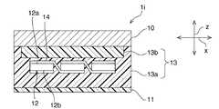
図1に示すように、太陽電池モジュール1aは、保護体10と、シート11と、充填剤層13と、太陽電池12とを備えている。 As shown in FIG. 1, the
(保護体10及びシート11)
保護体10と、シート11とは、太陽電池12の保護部材としての機能を有する。保護体10は、太陽電池モジュール1aの機械的強度を担保する部材である。保護体10は、剛性を有する部材である限りにおいて特に限定されない。保護体10は、ガラス板や樹脂板などにより構成することができる。なかでも、保護体10は、ガラス板により構成されていることが好ましい。ガラス板は、剛性及び光透過率が高く、かつ耐候性に優れているからである。(
The
なお、保護体10の厚さは、特に限定されない。保護体10の厚さは、例えば、3mm〜6mm程度とすることができる。 In addition, the thickness of the
シート11は、保護体10と対向している。シート11は、可撓性を有する部材である限りにおいて特に限定されない。シート11は、例えば、ポリエチレンテレフタレート(PET)などからなる樹脂シートなどにより構成することができる。なお、シート11を構成する樹脂シートの内部には、例えば、アルミニウム箔などの遮光箔や、水分透過性が低い無機バリア層等が設けられていてもよい。無機バリア層は、例えば、シリコン酸化物やアルミナなどの無機物により形成することができる。 The
なお、シート11の厚さは、特に限定されない。シート11の厚さは、例えば、150μm〜300μm程度とすることができる。 The thickness of the
充填剤層13は、保護体10とシート11との間に充填されている。充填剤層13は、太陽電池12を封止するための部材である。このため、充填剤層13は、封止層とも呼ばれる。この充填剤層13の構成については、後に詳述する。 The
(太陽電池12)
充填剤層13の内部には、複数の太陽電池12が配置されている。複数の太陽電池12は、保護体10,充填剤層13,シート11の積層方向zに対して垂直な配列方向xに沿って配列されている。複数の太陽電池12は、積層方向zを法線方向とする平面状にマトリクス状に配置されていてもよい。(Solar cell 12)
A plurality of
複数の太陽電池12は、配線材14によって、直列または並列に電気的に接続されている。なお、太陽電池12と配線材14との接着は、例えば、樹脂中に導電性粒子が分散している導電性樹脂接着剤や、半田などにより行うことができる。 The plurality of
本実施形態においては、複数の太陽電池12のそれぞれは、受光面12aが保護体10側を向き、裏面12bがシート11側を向くように配置されている。すなわち、本実施形態においては、複数の太陽電池12のそれぞれは、保護体10側からの光を受光する。但し、本発明は、この構成に限定されない。太陽電池は、例えば、受光面がシート側を向き、裏面が保護体側を向くように配置されていてもよい。また、太陽電池の両主面のそれぞれが受光面であってもよい。 In the present embodiment, each of the plurality of
太陽電池12の構造は、特に限定されない。太陽電池12は、例えば、HIT(登録商標)構造を有するHIT太陽電池であってもよいし、他の構造の太陽電池であってもよい。 The structure of the
一般的に、太陽電池12は、受光によりキャリア(電子及び正孔)を生成する光変換部を備えている。光変換部は、pn接合や、pin接合等の半導体接合を有する半導体材料から構成されている。半導体材料としては、例えば、単結晶シリコン、多結晶シリコンなどの結晶性シリコン半導体、非晶質シリコン半導体、GaAs等の化合物半導体などが挙げられる。 In general, the
光変換部の第1及び第2の主面のそれぞれには、キャリアを集電する電極が形成されている。この電極が、隣り合う太陽電池12間において配線材14により接続されることにより、複数の太陽電池12が電気的に接続されている。なお、電極は、一般的に、相互に平行に延びる複数のフィンガーと、フィンガーの延びる方向と垂直な方向に延びており、複数のフィンガーのそれぞれに接続されている1または複数のバスバーとを備えている。 Electrodes for collecting carriers are formed on each of the first and second main surfaces of the light conversion section. The electrodes are connected by the
(充填剤層13)
次に、本実施形態における充填剤層13の構成について詳細に説明する。(Filler layer 13)
Next, the configuration of the
充填剤層13は、第1の充填剤層13aと、第2の充填剤層13bとを有する。 The
第1の充填剤層13aは、シート11に接するように設けられている。本実施形態では、具体的には、シート11と保護体10との間に、第1の充填剤層13aと、第2の充填剤層13bとが、シート11側からこの順番で積層されている。シート11と第1の充填剤層13aとは接着されている。第1及び第2の充填剤層13a、13b間も接着されている。第2の充填剤層13bと保護体10とも接着されている。 The
太陽電池12は、第1の充填剤層13aと第2の充填剤層13bとの間の境界に配置されている。よって、第1の充填剤層13aは、太陽電池12に接している。なお、図1では、描画の便宜上、第1の充填剤層13aと第2の充填剤層13bとの間の境界は、積層方向zにおいて、太陽電池12が設けられた領域内に位置しているように描画しているが、例えば、積層方向zにおいて、太陽電池12の受光面12aや裏面12bと略面一であってもよい。 The
第1の充填剤層13aと第2の充填剤層13bとのそれぞれの積層方向zに沿った厚みは、特に限定されない。第1の充填剤層13aの積層方向zに沿った厚みは、例えば、0.3mm〜0.8mm程度であることが好ましい。第2の充填剤層13bの積層方向zに沿った厚みは、例えば、0.3mm〜0.8,mm程度であることが好ましい。充填剤層13全体の積層方向zに沿った厚みは、例えば、0.6mm〜2.0mm程度であることが好ましい。第1の充填剤層13aの積層方向zに沿った厚みと、第2の充填剤層13bの積層方向zに沿った厚みとの比は、1:2〜2:1の範囲内であることが好ましい。 The thickness along the stacking direction z of each of the
第1の充填剤層13aと第2の充填剤層13bとのそれぞれは、樹脂により形成されている。第1の充填剤層13aと第2の充填剤層13bとのそれぞれは、樹脂のみからなるものであってもよいし、樹脂の他に、例えば、架橋剤やカップリング剤などの残留物などが含まれているものであってもよい。 Each of the
第1及び第2の充填剤層13a、13bのそれぞれを形成している樹脂は、特に限定されないが、例えば、光透過性が高く、耐候性及び耐熱性に優れているエチレン・酢酸ビニル共重合体(EVA)やポリエチレンであることが好ましい。 The resin forming each of the first and second filler layers 13a and 13b is not particularly limited. For example, ethylene / vinyl acetate copolymer having high light transmission and excellent weather resistance and heat resistance. It is preferable that it is a combination (EVA) or polyethylene.
第1の充填剤層13aを形成している樹脂と、第2の充填剤層13bを形成している樹脂とのそれぞれのゲル分率は、0%より大きい。第2の充填剤層13bを形成している樹脂のゲル分率は、第1の充填剤層13aを形成している樹脂のゲル分率未満である。 The respective gel fractions of the resin forming the
具体的には、第1の充填剤層13aを形成している樹脂のゲル分率は、50%以上であることが好ましく、55%以上であることがさらに好ましく、60%以上であることがなお好ましい。但し、第1の充填剤層13aを形成している樹脂のゲル分率が高すぎると、柔軟性を保てない場合がある。このため、第1の充填剤層13aを形成している樹脂のゲル分率は、90%以下であることが好ましく、80%以下であることがより好ましい。 Specifically, the gel fraction of the resin forming the
第2の充填剤層13bを形成している樹脂のゲル分率は、80%未満であることが好ましく、60%以下であることがより好ましく、51%以下であることがさらに好ましく、40%以下であることがなお好ましい。 The gel fraction of the resin forming the
第1の充填剤層13aを形成している樹脂のゲル分率は、第2の充填剤層13bを形成している樹脂のゲル分率の1.5倍以上であることが好ましい。 The gel fraction of the resin forming the
なお、樹脂のゲル分率は、樹脂の架橋密度に相関するパラメータである。樹脂の架橋密度が高いほど、樹脂のゲル分率が高くなり、樹脂の架橋密度が低いほど、樹脂のゲル分率は低くなる傾向にある。このため、樹脂のゲル分率は、樹脂の架橋密度を変化させることによって調整することができる。樹脂の架橋密度は、例えば、架橋構造を形成するための架橋剤の添加量や、キュア時間を変化させることによって調整することができる。なお、架橋剤の種類は、樹脂の種類に応じて適宜選択することができる。架橋剤の具体例としては、有機過酸化物やシランカップリング剤などが挙げられる。有機過酸化物の具体例としては、ベンゾイルペルオキシド、ジクミルペルオキシド、2,5−ジメチル−2,5−ジ(t−ブチルペルオキシ)ヘキサンなどが挙げられる。シランカップリング剤の具体例としては、γ−メタクリロキシプロピルトリメトキシシラン、ポリシロキサンをベースとしてメトキシ基、エトキシ基などを導入した化合物などが挙げられる。 The gel fraction of the resin is a parameter that correlates with the crosslink density of the resin. The higher the crosslink density of the resin, the higher the gel fraction of the resin, and the lower the crosslink density of the resin, the lower the resin gel fraction. For this reason, the gel fraction of the resin can be adjusted by changing the crosslink density of the resin. The crosslinking density of the resin can be adjusted, for example, by changing the addition amount of a crosslinking agent for forming a crosslinked structure and the curing time. In addition, the kind of crosslinking agent can be suitably selected according to the kind of resin. Specific examples of the crosslinking agent include organic peroxides and silane coupling agents. Specific examples of the organic peroxide include benzoyl peroxide, dicumyl peroxide, 2,5-dimethyl-2,5-di (t-butylperoxy) hexane, and the like. Specific examples of the silane coupling agent include γ-methacryloxypropyltrimethoxysilane, a compound in which a methoxy group, an ethoxy group, or the like is introduced based on polysiloxane.
以上説明したように、本実施形態では、第2の充填剤層13bを形成している樹脂のゲル分率が、0%より高く、第1の充填剤層13aを形成している樹脂のゲル分率未満である。すなわち、第1及び第2の充填剤層13a、13bのそれぞれのゲル分率が0%より高く、シート11に接している第1の充填剤層13aを形成している樹脂のゲル分率が相対的に高く、第2の充填剤層13bを形成している樹脂のゲル分率が相対的に低い。このため、本実施形態の太陽電池モジュール1aでは、優れた耐候性と優れた耐熱性とを両立させることができる。 As described above, in the present embodiment, the gel fraction of the resin forming the
なお、本実施形態において、優れた耐熱性を実現できたのは、第1の充填剤層13aを形成している樹脂のゲル分率が高いため、第1の充填剤層13aを形成している樹脂の架橋密度が高く、可撓性の高いシート11に接している第1の充填剤層13aの高温時における流動性が低いためであると考えられる。また、優れた耐候性を実現できたのは、充填剤層13中に、ゲル分率が低く、水分透過性の低い第2の充填剤層13bを設けたためであると考えられる。但し、本実施形態において、充填剤層13の全体をゲル分率が高い樹脂により形成した場合とほぼ同等の耐熱性と、充填剤層13の全体をゲル分率が低い樹脂により形成した場合とほぼ同等の耐候性とを両立できた理由は、定かではない。 In the present embodiment, the excellent heat resistance can be achieved because the
第1の充填剤層13aを形成している樹脂のゲル分率が、60%以上である場合は、より高い耐熱性を実現することができる。第1の充填剤層13aを形成している樹脂のゲル分率は、50%以上であることがより好ましく、55%以上であることがさらに好ましく、60%以上であることがなお好ましい。但し、第1の充填剤層13aを形成している樹脂のゲル分率が高すぎると、樹脂の柔軟性を保てない場合がある。このため、第1の充填剤層13aを形成している樹脂のゲル分率は、80%以下であることが好ましい。 When the gel fraction of the resin forming the
第2の充填剤層13bを形成している樹脂のゲル分率が80%未満である場合は、より高い耐候性を実現することができる。第2の充填剤層13bを形成している樹脂のゲル分率は、60%以下であることがより好ましく、51%以下であることがさらに好ましく、40%以下であることがなお好ましい。 When the gel fraction of the resin forming the
第1の充填剤層13aを形成している樹脂のゲル分率が、第2の充填剤層13bを形成している樹脂のゲル分率の1.5倍以上である場合は、より優れた耐候性と、より優れた耐熱性とを有する太陽電池モジュールを実現することができる。 More excellent when the gel fraction of the resin forming the
第1及び第2の充填剤層13a、13bのそれぞれを形成している樹脂がEVAまたはポリエチレンである場合は、より優れた耐候性と、より優れた耐熱性を有すると共に、エネルギー効率の高い太陽電池モジュールを実現することができる。EVA及びポリエチレンは、共に、光透過性が高く、耐候性及び耐熱性に優れているためである。 When the resin forming each of the first and second filler layers 13a and 13b is EVA or polyethylene, the solar cell has better weather resistance, better heat resistance, and high energy efficiency. A battery module can be realized. This is because both EVA and polyethylene have high light transmittance and excellent weather resistance and heat resistance.
本実施形態では、高温時における流動性が低く、高温時における剛性が高い第1の充填剤層13aが太陽電池12に接するように設けられている。このため、より優れた耐熱性を実現することができる。 In the present embodiment, the
本実施形態では、太陽電池12の受光面12a側に配置されている保護体10は、水分透過性が低いガラス板により構成されている。このため、ガラス板側からは、太陽電池モジュール1a内に水分は進入しにくい。よって、太陽電池モジュール1aの出力に大きく影響する太陽電池12の受光面12a及び充填剤層13の受光面12a側に位置する部分が劣化しにくい。従って、太陽電池モジュール1aの耐候性をより改善することができる。 In the present embodiment, the
特に、本実施形態では、太陽電池12の受光面12a側に、ゲル分率が低く、水分透過性の低い第2の充填剤層13bが配置されており、水分透過性の高い第1の充填剤層13aは配置されていない。このため、太陽電池12の受光面12aに到達する水分をより少なくすることができる。よって、太陽電池12の受光面12aの劣化がより効果的に抑制されている。従って、太陽電池モジュール1aの耐候性をさらに改善することができる。 In particular, in this embodiment, the
なお、本実施形態に係る太陽電池モジュール1aは、例えば、以下に例示する製造方法により製造することができる。 In addition, the
まず、シート11の上に、第2の充填剤層13bを形成するための樹脂シートを1または複数枚配置する。その上に、配線材14により電気的に接続された複数の太陽電池12を配置し、さらにその上に、第1の充填剤層13aを形成するための樹脂シートを1または複数枚配置する。最後に、保護体10を積層する。形成された積層体を、減圧雰囲気中において、加熱圧着することにより、太陽電池モジュール1aを完成させることができる。 First, one or more resin sheets for forming the
以下、本発明を実施した好ましい形態の他の例について説明する。以下の説明において、上記実施形態と実質的に共通の機能を有する部材を共通の符号で参照し、説明を省略する。 Hereinafter, other examples of preferred embodiments of the present invention will be described. In the following description, members having substantially the same functions as those of the above embodiment are referred to by the same reference numerals, and description thereof is omitted.
《第2の実施形態》
図2は、第2の実施形態に係る太陽電池モジュール1bの略図的断面図である。<< Second Embodiment >>
FIG. 2 is a schematic cross-sectional view of a
図2に示すように、第2の実施形態では、ゲル分率の低い樹脂により形成されている第2の充填剤層13bが保護体10及びシート11の両方に接するように設けられている。具体的には、太陽電池モジュール1bの周縁部には、積層方向zにおいて保護体10からシート11にわたって第2の充填剤層13bが設けられている。すなわち、積層方向zから視た際に、第1の充填剤層13aの外側には、第2の充填剤層13bが設けられている。 As shown in FIG. 2, in the second embodiment, the
なお、第2の実施形態に係る太陽電池モジュール1bは、例えば、第1の充填剤層13aを形成するためのシートの面積を、第2の充填剤層13bを形成するためのシートの面積よりも小さくすることにより、上記第1の実施形態で説明した製造方法と実質的に同様の方法により製造することができる。 In the
《第3の実施形態》
図3は、第3の実施形態に係る太陽電池モジュール1cの略図的断面図である。<< Third Embodiment >>
FIG. 3 is a schematic cross-sectional view of a
図3に示すように、第3の実施形態では、ゲル分率の高い樹脂により形成されている第1の充填剤層13aが保護体10及びシート11の両方に接するように設けられている。具体的には、本実施形態では、太陽電池モジュール1cの周縁部には、積層方向zにおいて保護体10からシート11にわたって第1の充填剤層13aが設けられている。すなわち、積層方向zから視た際に、第2の充填剤層13bの外側には、第1の充填剤層13aが位置している。 As shown in FIG. 3, in the third embodiment, the
なお、第3の実施形態に係る太陽電池モジュール1cは、例えば、第2の充填剤層13bを形成するためのシートの面積を、第1の充填剤層13aを形成するためのシートの面積よりも小さくすることにより、上記第1の実施形態で説明した製造方法と実質的に同様の方法により製造することができる。 Note that, in the
《第4の実施形態》
図4は、第4の実施形態に係る太陽電池モジュール1dの略図的断面図である。<< Fourth Embodiment >>
FIG. 4 is a schematic cross-sectional view of a
上記第1〜第3の実施形態では、複数の太陽電池12が、第1の充填剤層13aと第2の充填剤層13bとの間の境界に配置されている例について説明した。それに対して第4の実施形態では、図4に示すように、第2の充填剤層13bが複数の太陽電池12よりもシート11側にまで至るように形成されており、太陽電池12は、第2の充填剤層13b内に配置されている。すなわち、太陽電池12は、ゲル分率の低い樹脂により形成されている第2の充填剤層13bによって包囲されている。 In the first to third embodiments, the example in which the plurality of
なお、第4の実施形態に係る太陽電池モジュール1dは、例えば、第1の充填剤層13aを形成するためのシートと太陽電池12との間に、第2の充填剤層13bを形成するためのシートを介在させることにより、上記第1の実施形態で説明した製造方法と実質的に同様の方法により製造することができる。 In addition, in the
《第5の実施形態》
図5は、第5の実施形態に係る太陽電池モジュール1eの略図的断面図である。<< Fifth Embodiment >>
FIG. 5 is a schematic cross-sectional view of a
図5に示すように、本実施形態の太陽電池モジュール1eの上記第4の実施形態の太陽電池モジュール1dと異なる点は、上記第3の実施形態と同様に、太陽電池モジュール1eの周縁部には、積層方向zにおいて第1の充填剤層13aが保護体10からシート11にわたって設けられている点である。このため、本実施形態では、積層方向zから視た際に、第2の充填剤層13bの外側には、第1の充填剤層13aが位置している。 As shown in FIG. 5, the
《第6の実施形態》
図6は、第6の実施形態に係る太陽電池モジュール1fの略図的断面図である。<< Sixth Embodiment >>
FIG. 6 is a schematic cross-sectional view of a
図6に示すように、本実施形態の太陽電池モジュール1fの第4の実施形態の太陽電池モジュール1dと異なる点は、上記第2の実施形態と同様に、太陽電池モジュール1fの周縁部には、積層方向zにおいて第2の充填剤層13bが保護体10からシート11にわたって設けられている点である。このため、本実施形態では、積層方向zから視た際に、第1の充填剤層13aの外側には、第2の充填剤層13bが位置している。 As shown in FIG. 6, the
《第7の実施形態》
図7は、第7の実施形態に係る太陽電池モジュール1gの略図的断面図である。<< Seventh Embodiment >>
FIG. 7 is a schematic cross-sectional view of a
図7に示すように、本実施形態の太陽電池モジュール1gの上記第1の実施形態の太陽電池モジュール1aとは異なる点は、第1の充填剤層13aが複数の太陽電池12よりも保護体10側にまで至るように形成されており、複数の太陽電池12が第1の充填剤層13a内に配置されている点である。 As shown in FIG. 7, the
なお、本実施形態の太陽電池モジュール1gは、第2の充填剤層13bを形成するためのシートの上に太陽電池12を配置する前に、第1の充填剤層13aを形成するためのシートを配置することにより、上記第1の実施形態において説明した製造方法と実質的に同様の製造方法により製造することができる。 In addition, the
《第8の実施形態》
図8は、第8の実施形態に係る太陽電池モジュール1hの略図的断面図である。<< Eighth Embodiment >>
FIG. 8 is a schematic cross-sectional view of a
図8に示すように、第8の実施形態の太陽電池モジュール1hの第7の実施形態の太陽電池モジュール1gと異なる点は、上記第2及び第6の実施形態と同様に、太陽電池モジュール1hの周縁部には、積層方向zにおいて第2の充填剤層13bが保護体10からシート11にわたって設けられている点である。このため、本実施形態では、積層方向zから視た際に、第1の充填剤層13aの外側には、第2の充填剤層13bが位置している。 As shown in FIG. 8, the
《第9の実施形態》
図9は、第9の実施形態に係る太陽電池モジュール1iの略図的断面図である。<< Ninth embodiment >>
FIG. 9 is a schematic cross-sectional view of a
図9に示すように、第9の実施形態の太陽電池モジュール1iの第7の実施形態の太陽電池モジュール1gと異なる点は、上記第3及び第5の実施形態と同様に、太陽電池モジュール1iの周縁部には、積層方向zにおいて第1の充填剤層13aが保護体10からシート11にわたって設けられている点である。このため、本実施形態では、積層方向zから視た際に、第2の充填剤層13bの外側には、第1の充填剤層13aが位置している。 As shown in FIG. 9, the
《第10〜第12の実施形態》
図10は、第10の実施形態に係る太陽電池モジュール1jの略図的断面図である。図11は、第11の実施形態に係る太陽電池モジュール1kの略図的断面図である。図12は、第12の実施形態に係る太陽電池モジュール1lの略図的断面図である。<< 10th to 12th embodiments >>
FIG. 10 is a schematic cross-sectional view of a solar cell module 1j according to the tenth embodiment. FIG. 11 is a schematic cross-sectional view of a
図10〜図12に示すように、第10〜第12の実施形態では、第1の充填剤層13aが保護体10及びシート11の両方に接している。第1の充填剤層13aは、第2の充填剤層13bを包囲するように設けられている。 As shown in FIGS. 10 to 12, in the tenth to twelfth embodiments, the
図10に示すように、第10の実施形態では、複数の太陽電池12は、第2の充填剤層13b内に配置されている。 As shown in FIG. 10, in the tenth embodiment, the plurality of
図11に示すように、第11の実施形態では、複数の太陽電池12は、第1の充填剤層13aと第2の充填剤層13bとの間の境界に配置されている。 As shown in FIG. 11, in the eleventh embodiment, the plurality of
図12に示すように、第12の実施形態では、複数の太陽電池12は、第1の充填剤層13a内に配置されている。 As shown in FIG. 12, in the twelfth embodiment, the plurality of
上記第2〜第12の実施形態に係る太陽電池モジュール1b〜1lにおいても、上記第1の実施形態に係る太陽電池モジュール1aと同様に、シート11に接するように、ゲル分率の高い樹脂により形成されている第1の充填剤層13aが設けられており、かつゲル分率の低い樹脂により形成されている第2の充填剤層13bが設けられている。このため、優れた耐候性及び優れた耐熱性の両立を図ることができる。 In the
また、第2,第3及び第11の実施形態においても、上記第1の実施形態と同様に、ゲル分率の高い樹脂により形成されている第1の充填剤層13aが複数の太陽電池12に接するように設けられている。従って、より優れた耐熱性を実現することができる。 Also in the second, third, and eleventh embodiments, as in the first embodiment, the
第2〜第6の実施形態においても、上記第1の実施形態と同様に、太陽電池12の受光面12a側に、ゲル分率の低い樹脂により形成されている第2の充填剤層13bが配置されており、ゲル分率の高い樹脂により形成されている第1の充填剤層13aは配置されていない。従って、より優れた耐熱性を実現することができる。 Also in the second to sixth embodiments, similarly to the first embodiment, the
第4〜第6及び第10の実施形態においては、複数の太陽電池12が第2の充填剤層13b内に配置されている。すなわち、複数の太陽電池12が、ゲル分率の低い樹脂により形成されている第2の充填剤層13bにより包囲されている。このため、複数の太陽電池12に水分が到達することをより効果的に抑制できる。よって、複数の太陽電池12の水分による劣化をより効果的に抑制することができる。従って、より優れた耐候性を実現することができる。 In the fourth to sixth and tenth embodiments, a plurality of
第7〜第9及び第12の実施形態では、複数の太陽電池12が第1の充填剤層13a内に配置されている。すなわち、複数の太陽電池12が、ゲル分率の高い樹脂により形成されている第1の充填剤層13aにより包囲されている。このため、高温雰囲気中においても、複数の太陽電池12が第1の充填剤層13aによって好適に保護される。従って、さらに優れた耐熱性を実現することができる。 In the seventh to ninth and twelfth embodiments, a plurality of
第3,第5及び第9〜第12の実施形態では、ゲル分率の高い樹脂により形成されている第1の充填剤層13aが保護体10とシート11との両方に接するように設けられている。このため、高温時において、充填剤層13の変形をより効果的に抑制することができる。特に、第3,第5及び第9〜第12の実施形態では、第2の充填剤層13bの外側に第1の充填剤層13aが位置している。よって、ゲル分率の低い樹脂により形成されている第2の充填剤層13bの高温における流動も効果的に抑制される。従って、より優れた耐熱性を実現することができる。 In the third, fifth and ninth to twelfth embodiments, the
なかでも、第10〜第12の実施形態では、第2の充填剤層13bが第1の充填剤層13aにより包囲されている。このため、第2の充填剤層13bの高温における流動をさらに効果的に抑制される。従って、さらに優れた耐熱性を実現することができる。 In particular, in the tenth to twelfth embodiments, the
第2,第6及び第8の実施形態では、ゲル分率の低い樹脂により形成されている第2の充填剤層13bが保護体10とシート11との両方に接するように設けられている。具体的には、太陽電池モジュール1b、1f、1hの周縁部には、積層方向zにおいて第2の充填剤層13bが保護体10からシート11にわたって設けられている。このため、太陽電池モジュール1b、1f、1hの周縁部からの太陽電池モジュール1b、1f、1h内への水分進入も効果的に抑制される。従って、より優れた耐候性を実現することができる。 In the second, sixth and eighth embodiments, the
《実施例》
(実施例1〜3、比較例1〜3)
実施例1〜3,比較例1〜3では、上記第1の実施形態に係る太陽電池モジュール1aと同様の構成を有する太陽電池モジュールA1〜A3(実施例1〜3)、B1〜B3(比較例1〜3)を以下の要領で作製した。"Example"
(Examples 1-3, Comparative Examples 1-3)
In Examples 1 to 3 and Comparative Examples 1 to 3, solar cell modules A1 to A3 (Examples 1 to 3) and B1 to B3 (comparison) having the same configuration as the
まず、ガラス板からなる保護体10の上に、充填剤として、架橋剤を含み、厚みが0.6mmであるEVAシートと、配線材14により電気的に接続された複数の太陽電池12と、充填剤として、架橋剤を含み、厚みが0.6mmであるEVAシートと、シート11とをこの順番で積層した。 First, on the
なお、各実施例及び各比較例において、第1の充填剤層13aを形成する樹脂に含まれる架橋剤の量及び第2の充填剤層13bを形成する樹脂に含まれる架橋剤の量は、下記の表1に示す通りである。なお、表1に示す架橋剤の量は、比較例1に係る太陽電池モジュールB1の作製時に添加した架橋剤の質量を100%としたときの相対的な質量割合である。 In each example and each comparative example, the amount of the crosslinking agent contained in the resin forming the
シート11としては、厚みが150μmであるポリエチレンテレフタレートシートを用いた。 As the
用いた太陽電池12の両表面には、相互に平行に延びる複数のフィンガーと、フィンガーと直交して設けられており、フィンガーの延びる方向に相互に隔離して配置されている2本のバスバーとが電極として設けられていた。 A plurality of fingers extending in parallel to each other on both surfaces of the
次に、得られた積層体をラミネート法を用いて一体化し、アルミニウムからなるフレーム内に収納することにより太陽電池モジュールを作製した。なお、ラミネート法による一体化は、減圧ポンプを用いて、5分間減圧した後、5分間圧着することにより行った。 Next, the obtained laminated body was integrated using a laminating method, and housed in a frame made of aluminum to produce a solar cell module. The integration by the laminating method was performed by reducing the pressure for 5 minutes using a vacuum pump and then pressure bonding for 5 minutes.
次に、150℃で加熱することにより、キュア工程を行った。添加した架橋剤の量及びキュア時間と、充填剤層13a、13bのゲル分率との関係を下記の表2に示す。この表2より、表1に示す各実施例及び比較例におけるゲル分率が得られる。 Next, the curing process was performed by heating at 150 ° C. The relationship between the amount of the added crosslinking agent and the curing time and the gel fraction of the filler layers 13a and 13b is shown in Table 2 below. From Table 2, the gel fraction in each Example and Comparative Example shown in Table 1 is obtained.

次に、実施例1〜3,比較例1〜3において作製した太陽電池モジュールについて、JIS C8991(2004年)に規定の高温高湿度試験及び温度サイクル試験を行った。 Next, the solar cell modules produced in Examples 1 to 3 and Comparative Examples 1 to 3 were subjected to a high temperature and high humidity test and a temperature cycle test specified in JIS C8991 (2004).
具体的には、高温高湿度試験は、太陽電池モジュールを温度:85±2℃、相対湿度:85±5%の範囲内の高温高湿槽中に、1000時間放置することにより行った。そして、高温高湿度試験前後における太陽電池モジュールの出力低下率((高温高湿度試験実施後の出力)/(高温高湿度試験実施前の出力))を測定した。また、高温高湿度試験前後における受光面12a上の2本のバスバー間の抵抗増大率(((高温高湿度試験実施後の抵抗)−(高温高湿度試験実施前の抵抗))/(高温高湿度試験実施前の抵抗))を測定した。 Specifically, the high-temperature and high-humidity test was performed by leaving the solar cell module in a high-temperature and high-humidity tank within a range of temperature: 85 ± 2 ° C. and relative humidity: 85 ± 5% for 1000 hours. And the output reduction rate ((output after implementation of a high-temperature, high-humidity test) / (output before implementation of a high-temperature, high-humidity test)) before and after the high-temperature, high-humidity test was measured. Also, the resistance increase rate between the two bus bars on the
温度サイクル試験は、作製した太陽電池モジュールの両端子間に導通監視装置を接続すると共に、絶縁性監視装置を太陽電池モジュールの一方の端子と、フレームとの間に接続した状態で、太陽電池モジュールの温度を−40±2℃の範囲内の温度から、100℃/時間で90±2℃の範囲内の温度にまで昇温し、10分保持した後に、−40±2℃の範囲内の温度まで、100℃/時間で冷却し、10分保持した後に、再度、100℃/時間で90±2℃の範囲内の温度にまで昇温するサイクルを200サイクル実施することにより行った。この試験中において、太陽電池モジュール周囲の空気は、2m/秒で循環させた。また、試験中において、太陽電池モジュールには、AMが1.5で、100mW/cm2の強度の光を照射した。そして、温度サイクル試験前後における太陽電池モジュールの出力低下率((温度サイクル試験実施後の出力)/(温度サイクル試験実施前の出力))を測定した。In the temperature cycle test, the continuity monitoring device is connected between both terminals of the produced solar cell module, and the solar cell module is connected with the insulation monitoring device between one terminal of the solar cell module and the frame. The temperature was raised from a temperature within the range of −40 ± 2 ° C. to a temperature within the range of 90 ± 2 ° C. at 100 ° C./hour, held for 10 minutes, and then within a range of −40 ± 2 ° C. After cooling to 100 ° C./hour and holding for 10 minutes, the temperature was raised again to a temperature within the range of 90 ± 2 ° C. at 100 ° C./hour by carrying out 200 cycles. During this test, the air around the solar cell module was circulated at 2 m / sec. During the test, the solar cell module was irradiated with light having an AM of 1.5 and an intensity of 100 mW / cm2 . And the output reduction rate ((output after temperature cycle test implementation) / (output before temperature cycle test implementation)) of the solar cell module before and after the temperature cycle test was measured.
結果を、下記の表3に示す。また、図13に、第1の充填剤層13aにおける樹脂のゲル分率が80%である太陽電池モジュールA1,A2,B1の高温高湿度試験及び温度サイクル試験のそれぞれにおける出力低下率と、第2の充填剤層における樹脂のゲル分率との関係を表すグラフを示す。図14に、第2の充填剤層13bにおける樹脂のゲル分率が2%である太陽電池モジュールA2,A3,B2の高温高湿度試験及び温度サイクル試験のそれぞれにおける出力低下率と、第1の充填剤層における樹脂のゲル分率との関係を表すグラフを示す。 The results are shown in Table 3 below. Further, FIG. 13 shows the output reduction rate in each of the high-temperature and high-humidity test and the temperature cycle test of the solar cell modules A1, A2, and B1 in which the gel fraction of the resin in the
上記表3に示す結果から、第2の充填剤層13bを形成している樹脂のゲル分率が、0%よりも大きく、かつ、第1の充填剤層13aを形成している樹脂のゲル分率未満である太陽電池モジュールA1〜A3は、優れた耐熱性及び優れた耐候性を有することが分かる。 From the results shown in Table 3, the gel fraction of the resin forming the
一方、第1の充填剤層13aを形成している樹脂のゲル分率と、第2の充填剤層13bを形成している樹脂のゲル分率とが等しい太陽電池モジュールB1,B2では、耐熱性または耐候性が劣悪であった。具体的には、第1及び第2の充填剤層13a、13bを形成している樹脂のゲル分率が高い太陽電池モジュールB1は、耐候性が劣悪であった。一方、第1及び第2の充填剤層13a、13bを形成している樹脂のゲル分率が低い太陽電池モジュールB2は、耐熱性が劣悪であった。 On the other hand, in the solar cell modules B1 and B2 in which the gel fraction of the resin forming the
第2の充填剤層13bを形成している樹脂のゲル分率が0%である太陽電池モジュールB3も、耐熱性が劣悪であった。 The solar cell module B3 in which the gel fraction of the resin forming the
図13に示す結果から、高温高湿度試験における出力低下率は、第2の充填剤層13bにおける樹脂のゲル分率が大きくなるにしたがって大きくなることが分かる。一方、温度サイクル試験における出力低下率は、第2の充填剤層13bにおける樹脂のゲル分率が変化しても大きくは変化しないことが分かる。すなわち、第2の充填剤層13bにおける樹脂のゲル分率は、耐候性に大きく関与する一方、耐熱性にはそれほど関与しないことが分かる。また、第2の充填剤層13bにおける樹脂のゲル分率を小さくすることによって、優れた耐候性が得られることが分かる。図14に示す結果から、高温高湿度試験における出力低下率は、第1の充填剤層13aにおける樹脂のゲル分率が変化しても大きくは変化しないことが分かる。一方、温度サイクル試験における出力低下率は、第1の充填剤層13aにおける樹脂のゲル分率が小さくなるにしたがって大きくなることが分かる。すなわち、第1の充填剤層13aにおける樹脂のゲル分率は、耐熱性に大きく関与する一方、耐候性にはそれほど関与しないことが分かる。また、第1の充填剤層13aにおける樹脂のゲル分率を大きくすることによって、優れた耐熱性が得られることが分かる。 From the results shown in FIG. 13, it can be seen that the output reduction rate in the high temperature and high humidity test increases as the resin gel fraction in the
以上の結果から、第2の充填剤層13bを形成している樹脂のゲル分率を、0%よりも大きく、かつ、第1の充填剤層13aを形成している樹脂のゲル分率未満とすることにより、優れた耐熱性と優れた耐候性とを両立できることが分かる。 From the above results, the gel fraction of the resin forming the
図14に示すように、第1の充填剤層13aにおける樹脂のゲル分率が55%未満である場合は、第1の充填剤層13aにおける樹脂のゲル分率が小さくなるに従う温度サイクル試験における出力低下率の増大率が大きかった。それに対して、第1の充填剤層13aにおける樹脂のゲル分率が55%以上である場合は、第1の充填剤層13aにおける樹脂のゲル分率に関わらず、温度サイクル試験における出力低下率は低かった。特に、第1の充填剤層13aにおける樹脂のゲル分率が60%以上である場合は、第1の充填剤層13aにおける樹脂のゲル分率の変化に伴う温度サイクル試験における出力低下率の変化量が少なかった。以上の結果から、第1の充填剤層13aにおける樹脂のゲル分率は、55%以上であることが好ましく、60%以上であることがより好ましいことが分かる。 As shown in FIG. 14, when the gel fraction of the resin in the
図13に示すように、第2の充填剤層13bにおける樹脂のゲル分率が51%より大きい場合は、第2の充填剤層13bにおける樹脂のゲル分率が大きくなるに従う高温高湿度試験における出力低下率の増大率が大きかった。それに対して、第2の充填剤層13bにおける樹脂のゲル分率が51%以下である場合は、第2の充填剤層における樹脂のゲル分率に関わらず、高温高湿度試験における出力低下率は低かった。特に、第2の充填剤層13bにおける樹脂のゲル分率が40%以下である場合は、第2の充填剤層13bにおける樹脂のゲル分率の変化に伴う高温高湿度試験における出力低下率の変化量が少なかった。以上の結果から、第2の充填剤層13bにおける樹脂のゲル分率は、51%以下であることが好ましく、40%以下であることがより好ましいことが分かる。 As shown in FIG. 13, when the resin gel fraction in the
1a〜1l…太陽電池モジュール
10…保護体
11…シート
12…太陽電池
12a…太陽電池の受光面
12b…太陽電池の裏面
13…充填剤層
13a…第1の充填剤層
13b…第2の充填剤層
14…配線材DESCRIPTION OF
Claims (5)
Translated fromJapanese前記保護体に対向しているシートと、
前記保護体と前記シートとの間に設けられている充填剤層と、
前記充填剤層内に配置されている太陽電池とを備え、
前記充填剤層は、前記シートに接するように設けられており、樹脂により形成されている第1の充填剤層と、ゲル分率が、0%よりも高く、前記第1の充填剤層を形成している樹脂のゲル分率未満である樹脂により形成されている第2の充填剤層とを有する太陽電池モジュール。A protector,
A sheet facing the protector;
A filler layer provided between the protective body and the sheet;
A solar cell disposed in the filler layer,
The filler layer is provided so as to be in contact with the sheet, and the first filler layer formed of a resin has a gel fraction higher than 0%, and the first filler layer is The solar cell module which has a 2nd filler layer formed with resin which is less than the gel fraction of the resin currently formed.
Priority Applications (4)
| Application Number | Priority Date | Filing Date | Title |
|---|---|---|---|
| JP2010040678AJP2011176231A (en) | 2010-02-25 | 2010-02-25 | Solar cell module |
| PCT/JP2011/053896WO2011105389A1 (en) | 2010-02-25 | 2011-02-23 | Solar cell module |
| EP11747350.4AEP2549549B1 (en) | 2010-02-25 | 2011-02-23 | Solar cell module |
| US13/593,904US8952241B2 (en) | 2010-02-25 | 2012-08-24 | Solar cell module |
Applications Claiming Priority (1)
| Application Number | Priority Date | Filing Date | Title |
|---|---|---|---|
| JP2010040678AJP2011176231A (en) | 2010-02-25 | 2010-02-25 | Solar cell module |
Publications (1)
| Publication Number | Publication Date |
|---|---|
| JP2011176231Atrue JP2011176231A (en) | 2011-09-08 |
Family
ID=44506795
Family Applications (1)
| Application Number | Title | Priority Date | Filing Date |
|---|---|---|---|
| JP2010040678APendingJP2011176231A (en) | 2010-02-25 | 2010-02-25 | Solar cell module |
Country Status (4)
| Country | Link |
|---|---|
| US (1) | US8952241B2 (en) |
| EP (1) | EP2549549B1 (en) |
| JP (1) | JP2011176231A (en) |
| WO (1) | WO2011105389A1 (en) |
Cited By (15)
| Publication number | Priority date | Publication date | Assignee | Title |
|---|---|---|---|---|
| WO2013084849A1 (en)* | 2011-12-05 | 2013-06-13 | 大日本印刷株式会社 | Solar cell module |
| WO2013094502A1 (en)* | 2011-12-22 | 2013-06-27 | 三洋電機株式会社 | Solar battery module |
| WO2013132602A1 (en) | 2012-03-07 | 2013-09-12 | 三洋電機株式会社 | Solar cell module |
| JP2014003118A (en)* | 2012-06-18 | 2014-01-09 | Mitsui Chemicals Tohcello Inc | Solar cell sealing sheet, and solar cell module and method for manufacturing the same |
| JP2014027290A (en)* | 2013-09-02 | 2014-02-06 | Dainippon Printing Co Ltd | Solar cell module |
| JP2014030027A (en)* | 2013-09-02 | 2014-02-13 | Dainippon Printing Co Ltd | Method for manufacturing solar battery module |
| JP2014036044A (en)* | 2012-08-07 | 2014-02-24 | Sharp Corp | Solar cell module |
| JPWO2013069680A1 (en)* | 2011-11-10 | 2015-04-02 | 三洋電機株式会社 | Solar cell module |
| JP2015517223A (en)* | 2012-04-25 | 2015-06-18 | コミッサリア ア レネルジー アトミーク エ オ ゼネルジ ザルタナテイヴ | Solar cell module with specific structure |
| JP2015119008A (en)* | 2013-12-17 | 2015-06-25 | 株式会社カネカ | Solar battery module and method for manufacturing the same |
| JPWO2013132654A1 (en)* | 2012-03-09 | 2015-07-30 | パナソニックIpマネジメント株式会社 | Solar cell module and manufacturing method thereof |
| JP6057113B1 (en)* | 2016-06-13 | 2017-01-11 | パナソニックIpマネジメント株式会社 | Solar cell module and manufacturing method thereof |
| JP2017050571A (en)* | 2016-12-09 | 2017-03-09 | 三井化学東セロ株式会社 | Solar battery-sealing sheet, and solar battery module and manufacturing method thereof |
| JP2017108170A (en)* | 2017-03-02 | 2017-06-15 | パナソニックIpマネジメント株式会社 | Solar battery module and manufacturing method for the same |
| WO2017208793A1 (en)* | 2016-05-31 | 2017-12-07 | パナソニックIpマネジメント株式会社 | Solar cell module and manufacturing method thereof |
Families Citing this family (1)
| Publication number | Priority date | Publication date | Assignee | Title |
|---|---|---|---|---|
| WO2016153007A1 (en)* | 2015-03-26 | 2016-09-29 | 株式会社カネカ | Solar battery module and method for producing same |
Citations (3)
| Publication number | Priority date | Publication date | Assignee | Title |
|---|---|---|---|---|
| JPH10341030A (en)* | 1997-06-09 | 1998-12-22 | Canon Inc | Solar cell module |
| JPH11112007A (en)* | 1997-10-02 | 1999-04-23 | Canon Inc | Solar cell module and method of manufacturing the same |
| JPH11261085A (en)* | 1998-03-10 | 1999-09-24 | Mitsubishi Plastics Ind Ltd | Backsheet for solar cell |
Family Cites Families (6)
| Publication number | Priority date | Publication date | Assignee | Title |
|---|---|---|---|---|
| JP2004214641A (en)* | 2002-12-16 | 2004-07-29 | Dainippon Printing Co Ltd | Filler sheet for solar cell module and solar cell module using the same |
| JP4644854B2 (en) | 2003-10-03 | 2011-03-09 | 三井・デュポンポリケミカル株式会社 | Sheet for solar cell encapsulant |
| JP4662805B2 (en)* | 2005-04-21 | 2011-03-30 | 積水化学工業株式会社 | Manufacturing method of adhesive sheet for solar cell |
| JP4667406B2 (en)* | 2006-03-30 | 2011-04-13 | 三洋電機株式会社 | Solar cell module and manufacturing method thereof |
| US20080041434A1 (en)* | 2006-08-18 | 2008-02-21 | Nanosolar, Inc. | Methods and devices for large-scale solar installations |
| JP5484663B2 (en)* | 2007-09-25 | 2014-05-07 | 三洋電機株式会社 | Manufacturing method of solar cell module |
- 2010
- 2010-02-25JPJP2010040678Apatent/JP2011176231A/enactivePending
- 2011
- 2011-02-23EPEP11747350.4Apatent/EP2549549B1/enactiveActive
- 2011-02-23WOPCT/JP2011/053896patent/WO2011105389A1/enactiveApplication Filing
- 2012
- 2012-08-24USUS13/593,904patent/US8952241B2/enactiveActive
Patent Citations (3)
| Publication number | Priority date | Publication date | Assignee | Title |
|---|---|---|---|---|
| JPH10341030A (en)* | 1997-06-09 | 1998-12-22 | Canon Inc | Solar cell module |
| JPH11112007A (en)* | 1997-10-02 | 1999-04-23 | Canon Inc | Solar cell module and method of manufacturing the same |
| JPH11261085A (en)* | 1998-03-10 | 1999-09-24 | Mitsubishi Plastics Ind Ltd | Backsheet for solar cell |
Cited By (20)
| Publication number | Priority date | Publication date | Assignee | Title |
|---|---|---|---|---|
| JP2018014542A (en)* | 2011-11-10 | 2018-01-25 | パナソニックIpマネジメント株式会社 | Solar cell module |
| JPWO2013069680A1 (en)* | 2011-11-10 | 2015-04-02 | 三洋電機株式会社 | Solar cell module |
| JP2013118328A (en)* | 2011-12-05 | 2013-06-13 | Dainippon Printing Co Ltd | Solar cell module |
| WO2013084849A1 (en)* | 2011-12-05 | 2013-06-13 | 大日本印刷株式会社 | Solar cell module |
| TWI553893B (en)* | 2011-12-05 | 2016-10-11 | Dainippon Printing Co Ltd | Solar module |
| WO2013094502A1 (en)* | 2011-12-22 | 2013-06-27 | 三洋電機株式会社 | Solar battery module |
| JPWO2013094502A1 (en)* | 2011-12-22 | 2015-04-27 | 三洋電機株式会社 | Solar cell module |
| WO2013132602A1 (en) | 2012-03-07 | 2013-09-12 | 三洋電機株式会社 | Solar cell module |
| JPWO2013132654A1 (en)* | 2012-03-09 | 2015-07-30 | パナソニックIpマネジメント株式会社 | Solar cell module and manufacturing method thereof |
| JP2015517223A (en)* | 2012-04-25 | 2015-06-18 | コミッサリア ア レネルジー アトミーク エ オ ゼネルジ ザルタナテイヴ | Solar cell module with specific structure |
| JP2014003118A (en)* | 2012-06-18 | 2014-01-09 | Mitsui Chemicals Tohcello Inc | Solar cell sealing sheet, and solar cell module and method for manufacturing the same |
| JP2014036044A (en)* | 2012-08-07 | 2014-02-24 | Sharp Corp | Solar cell module |
| JP2014027290A (en)* | 2013-09-02 | 2014-02-06 | Dainippon Printing Co Ltd | Solar cell module |
| JP2014030027A (en)* | 2013-09-02 | 2014-02-13 | Dainippon Printing Co Ltd | Method for manufacturing solar battery module |
| JP2015119008A (en)* | 2013-12-17 | 2015-06-25 | 株式会社カネカ | Solar battery module and method for manufacturing the same |
| WO2017208793A1 (en)* | 2016-05-31 | 2017-12-07 | パナソニックIpマネジメント株式会社 | Solar cell module and manufacturing method thereof |
| CN109451766A (en)* | 2016-05-31 | 2019-03-08 | 松下知识产权经营株式会社 | Solar cell module and method of manufacturing same |
| JP6057113B1 (en)* | 2016-06-13 | 2017-01-11 | パナソニックIpマネジメント株式会社 | Solar cell module and manufacturing method thereof |
| JP2017050571A (en)* | 2016-12-09 | 2017-03-09 | 三井化学東セロ株式会社 | Solar battery-sealing sheet, and solar battery module and manufacturing method thereof |
| JP2017108170A (en)* | 2017-03-02 | 2017-06-15 | パナソニックIpマネジメント株式会社 | Solar battery module and manufacturing method for the same |
Also Published As
| Publication number | Publication date |
|---|---|
| WO2011105389A1 (en) | 2011-09-01 |
| US20120312359A1 (en) | 2012-12-13 |
| EP2549549B1 (en) | 2018-04-04 |
| US8952241B2 (en) | 2015-02-10 |
| EP2549549A4 (en) | 2016-05-04 |
| EP2549549A1 (en) | 2013-01-23 |
Similar Documents
| Publication | Publication Date | Title |
|---|---|---|
| JP2011176231A (en) | Solar cell module | |
| JP2011159711A (en) | Solar cell module | |
| JP5484663B2 (en) | Manufacturing method of solar cell module | |
| CN1112734C (en) | Solar cell module having surface coating material for three-layer structure | |
| KR101215694B1 (en) | Solar Cell Module And Manufacturing Method Thereof | |
| JP5014503B2 (en) | Solar cell and solar cell module | |
| JPH0936405A (en) | Solar cell module and method of manufacturing the same | |
| CN203225264U (en) | Foldable type large format flexible solar cell assembly | |
| CN207474483U (en) | Flexible photovoltaic component | |
| US20160308081A1 (en) | Solar cell module | |
| JPWO2011099538A1 (en) | Solar cell module and method for manufacturing solar cell module | |
| JP2012253063A (en) | Solar cell module | |
| CN212161828U (en) | Photovoltaic module | |
| CN102437215A (en) | Intra-laminate disk layer for thin film photovoltaic devices and their methods of manufacture | |
| CN111416010B (en) | High-voltage protection design structure of solar cell circuit and preparation method thereof | |
| US20170323986A1 (en) | Photovoltaic module | |
| CN101047211B (en) | solar cell module | |
| JP2011210747A (en) | Solar cell module and method of manufacturing the same | |
| EP2535947A1 (en) | Solar cell module and production method for solar cell module | |
| CN105556683B (en) | Solar module | |
| CN117393629A (en) | Solar cells, solar modules and photovoltaic modules | |
| JP2015195375A (en) | Solar cell module | |
| JP5014502B2 (en) | Method for manufacturing solar cell and method for manufacturing solar cell module | |
| JP2016025119A (en) | Solar cell module and method for manufacturing solar cell module | |
| KR20150049259A (en) | Junction box and photovoltaic module comprising the same |
Legal Events
| Date | Code | Title | Description |
|---|---|---|---|
| A621 | Written request for application examination | Free format text:JAPANESE INTERMEDIATE CODE: A621 Effective date:20130122 | |
| A131 | Notification of reasons for refusal | Free format text:JAPANESE INTERMEDIATE CODE: A131 Effective date:20140128 | |
| A521 | Request for written amendment filed | Free format text:JAPANESE INTERMEDIATE CODE: A523 Effective date:20140326 | |
| A02 | Decision of refusal | Free format text:JAPANESE INTERMEDIATE CODE: A02 Effective date:20140924 | |
| A521 | Request for written amendment filed | Free format text:JAPANESE INTERMEDIATE CODE: A523 Effective date:20141218 | |
| A911 | Transfer to examiner for re-examination before appeal (zenchi) | Free format text:JAPANESE INTERMEDIATE CODE: A911 Effective date:20141226 | |
| A711 | Notification of change in applicant | Free format text:JAPANESE INTERMEDIATE CODE: A711 Effective date:20150224 | |
| A912 | Re-examination (zenchi) completed and case transferred to appeal board | Free format text:JAPANESE INTERMEDIATE CODE: A912 Effective date:20150227 |