JP2011171009A - Focused ion beam device - Google Patents
Focused ion beam deviceDownload PDFInfo
- Publication number
- JP2011171009A JP2011171009AJP2010031605AJP2010031605AJP2011171009AJP 2011171009 AJP2011171009 AJP 2011171009AJP 2010031605 AJP2010031605 AJP 2010031605AJP 2010031605 AJP2010031605 AJP 2010031605AJP 2011171009 AJP2011171009 AJP 2011171009A
- Authority
- JP
- Japan
- Prior art keywords
- ion beam
- ion
- sample
- gun
- electrode
- Prior art date
- Legal status (The legal status is an assumption and is not a legal conclusion. Google has not performed a legal analysis and makes no representation as to the accuracy of the status listed.)
- Pending
Links
Images


Classifications
- H—ELECTRICITY
- H01—ELECTRIC ELEMENTS
- H01J—ELECTRIC DISCHARGE TUBES OR DISCHARGE LAMPS
- H01J3/00—Details of electron-optical or ion-optical arrangements or of ion traps common to two or more basic types of discharge tubes or lamps
- H01J3/14—Arrangements for focusing or reflecting ray or beam
- H—ELECTRICITY
- H01—ELECTRIC ELEMENTS
- H01J—ELECTRIC DISCHARGE TUBES OR DISCHARGE LAMPS
- H01J27/00—Ion beam tubes
- H01J27/02—Ion sources; Ion guns
- H01J27/26—Ion sources; Ion guns using surface ionisation, e.g. field effect ion sources, thermionic ion sources
- H—ELECTRICITY
- H01—ELECTRIC ELEMENTS
- H01J—ELECTRIC DISCHARGE TUBES OR DISCHARGE LAMPS
- H01J3/00—Details of electron-optical or ion-optical arrangements or of ion traps common to two or more basic types of discharge tubes or lamps
- H01J3/26—Arrangements for deflecting ray or beam
- H—ELECTRICITY
- H01—ELECTRIC ELEMENTS
- H01J—ELECTRIC DISCHARGE TUBES OR DISCHARGE LAMPS
- H01J37/00—Discharge tubes with provision for introducing objects or material to be exposed to the discharge, e.g. for the purpose of examination or processing thereof
- H01J37/02—Details
- H01J37/04—Arrangements of electrodes and associated parts for generating or controlling the discharge, e.g. electron-optical arrangement or ion-optical arrangement
- H01J37/08—Ion sources; Ion guns
- H—ELECTRICITY
- H01—ELECTRIC ELEMENTS
- H01J—ELECTRIC DISCHARGE TUBES OR DISCHARGE LAMPS
- H01J37/00—Discharge tubes with provision for introducing objects or material to be exposed to the discharge, e.g. for the purpose of examination or processing thereof
- H01J37/26—Electron or ion microscopes; Electron or ion diffraction tubes
- H01J37/28—Electron or ion microscopes; Electron or ion diffraction tubes with scanning beams
- H—ELECTRICITY
- H01—ELECTRIC ELEMENTS
- H01J—ELECTRIC DISCHARGE TUBES OR DISCHARGE LAMPS
- H01J37/00—Discharge tubes with provision for introducing objects or material to be exposed to the discharge, e.g. for the purpose of examination or processing thereof
- H01J37/30—Electron-beam or ion-beam tubes for localised treatment of objects
- H01J37/305—Electron-beam or ion-beam tubes for localised treatment of objects for casting, melting, evaporating, or etching
- H01J37/3053—Electron-beam or ion-beam tubes for localised treatment of objects for casting, melting, evaporating, or etching for evaporating or etching
- H01J37/3056—Electron-beam or ion-beam tubes for localised treatment of objects for casting, melting, evaporating, or etching for evaporating or etching for microworking, e. g. etching of gratings or trimming of electrical components
- H—ELECTRICITY
- H01—ELECTRIC ELEMENTS
- H01J—ELECTRIC DISCHARGE TUBES OR DISCHARGE LAMPS
- H01J2237/00—Discharge tubes exposing object to beam, e.g. for analysis treatment, etching, imaging
- H01J2237/06—Sources
- H01J2237/08—Ion sources
- H01J2237/0802—Field ionization sources
- H01J2237/0807—Gas field ion sources [GFIS]
- H—ELECTRICITY
- H01—ELECTRIC ELEMENTS
- H01J—ELECTRIC DISCHARGE TUBES OR DISCHARGE LAMPS
- H01J2237/00—Discharge tubes exposing object to beam, e.g. for analysis treatment, etching, imaging
- H01J2237/30—Electron or ion beam tubes for processing objects
- H01J2237/317—Processing objects on a microscale
- H01J2237/31749—Focused ion beam
Landscapes
- Chemical & Material Sciences (AREA)
- Analytical Chemistry (AREA)
- Engineering & Computer Science (AREA)
- Combustion & Propulsion (AREA)
- Physics & Mathematics (AREA)
- Plasma & Fusion (AREA)
- Electron Sources, Ion Sources (AREA)
Abstract
Translated fromJapaneseDescription
Translated fromJapanese電界電離型イオン源を備えた集束イオンビーム装置に関する。 The present invention relates to a focused ion beam apparatus including a field ion source.
従来、集束イオンビーム装置のイオン源として液体金属ガリウムを用いられている。また、近年では、微細なチップにイオン源ガスを供給して、チップ先端に形成された強力な電界により、チップに吸着したイオン源ガス種をイオン化し、イオンビームを引き出す電界電離型イオン源を用いた集束イオンビームも開発されている。 Conventionally, liquid metal gallium has been used as an ion source of a focused ion beam apparatus. In recent years, an ionization ion source that supplies ion source gas to a fine chip, ionizes ion source gas species adsorbed on the chip by a strong electric field formed at the tip of the chip, and extracts an ion beam has been developed. The focused ion beam used has also been developed.
従来の液体金属ガリウムを用いたイオン源では、イオン源から放出されるイオンビームの開き角度は20度程度であった。一方、電界電離型イオン源では、イオンビームはチップ先端の数個の原子から放出されるため、イオンビームの開き角度は数度程度である。電界電離型イオン源を用いる場合、イオンビーム開き角度が小さいため、イオン源から試料表面に到達するイオンビームを引き出すためにイオン鏡筒内で光軸に対して、角度、位置の正確な調整が必要であった。 In the conventional ion source using liquid metal gallium, the opening angle of the ion beam emitted from the ion source is about 20 degrees. On the other hand, in the field ionization type ion source, since the ion beam is emitted from several atoms at the tip of the tip, the opening angle of the ion beam is about several degrees. When using a field ionization ion source, the ion beam opening angle is small, so that the angle and position of the ion beam can be adjusted accurately with respect to the optical axis in order to extract the ion beam that reaches the sample surface from the ion source. It was necessary.
チップ自体の方向を調整する調整機構を備えた電界電離型イオン源が知られている(特許文献1参照)。 A field ionization ion source having an adjustment mechanism for adjusting the direction of the chip itself is known (see Patent Document 1).
このように構成された装置によれば、イオンビームの開き角度の小さい電界電離型イオン源でもイオンビーム引き出しの調整を正確な測定を行うことが可能となる。 According to the apparatus configured as described above, the ion beam extraction can be accurately adjusted even in a field ionization ion source having a small ion beam opening angle.
しかしながら、このような調整機構は複雑な構造であり、調整機構を備えた装置では高価なものになってしまう。また、この機構ではチップが振動の影響を受けて安定したビームを照射することができない。 However, such an adjustment mechanism has a complicated structure, and an apparatus including the adjustment mechanism becomes expensive. Further, with this mechanism, the tip cannot be irradiated with a stable beam due to the influence of vibration.
この発明は、上記の事情を考慮してなされたもので、その目的は、複雑な構造を用いることなく安定したビームを照射可能な集束イオンビーム装置を提供することである。 The present invention has been made in view of the above circumstances, and an object of the present invention is to provide a focused ion beam apparatus that can irradiate a stable beam without using a complicated structure.
上記の目的を達成するために、この発明は以下の手段を提供している。
本発明に係る集束イオンビーム装置は、針状のチップと、チップにガスを供給するガス供給部と、チップとの間で電圧を印加し、チップ表面に吸着したガスをイオン化してイオンを引き出す引出電極と、イオンを試料に向けて加速させるカソード電極と、を有する電界電離型イオン銃部と、電界電離型イオン銃部から放出されたイオンビームの照射方向を調整するガンアライメント電極と、試料にイオンビームを集束させるレンズ系と、を有する。In order to achieve the above object, the present invention provides the following means.
The focused ion beam device according to the present invention applies a voltage between a needle-shaped tip, a gas supply unit that supplies gas to the tip, and the tip, ionizes the gas adsorbed on the tip surface, and extracts ions. A field ionization ion gun unit having an extraction electrode and a cathode electrode for accelerating ions toward the sample; a gun alignment electrode for adjusting the irradiation direction of the ion beam emitted from the field ionization ion gun unit; And a lens system for focusing the ion beam.
この発明に係る集束イオンビーム装置においては、電界電離型イオン銃部から放出されたイオンビームをガンアライメント電極で偏向することができる。これによりチップ自体の方向を調整するような複雑で高価な機能を必要とせず、また外部からの振動に対しても強い装置を実現することができる。 In the focused ion beam apparatus according to the present invention, the ion beam emitted from the field ionization type ion gun can be deflected by the gun alignment electrode. As a result, a complicated and expensive function for adjusting the direction of the chip itself is not required, and a device that is strong against external vibration can be realized.
この発明に係る集束イオンビーム装置においては、レンズ系は、ガンアライメント電極よりも試料側に配置する。これによりイオンビームを光軸に平行に調整することができるので、レンズ等光学系に斜めに入射することにより発生する収差の小さいイオンビームを試料に照射することができる。ここで光軸とはレンズの中心を貫く軸である。 In the focused ion beam apparatus according to the present invention, the lens system is disposed closer to the sample than the gun alignment electrode. Accordingly, since the ion beam can be adjusted parallel to the optical axis, the sample can be irradiated with an ion beam having a small aberration caused by obliquely entering an optical system such as a lens. Here, the optical axis is an axis that penetrates the center of the lens.
また、ガンアライメント電極に走査信号を入力することで、アパーチャ上にイオンビームを走査照射することができる。これにより二次荷電粒子像を観察することで、アパーチャの位置を確認することができる。 Further, by inputting a scanning signal to the gun alignment electrode, the ion beam can be scanned and irradiated onto the aperture. Accordingly, the position of the aperture can be confirmed by observing the secondary charged particle image.
この発明に係る集束イオンビーム装置においては、ガンアライメント電極を通過したイオンビームの一部を通過させる開口部を有するアパーチャを有する。これによりガンアライメント電極で偏向されたイオンビームの光軸中心付近のイオンビームのみを開口部から通過させることができる。従って、集束レンズにはイオンビームの光軸中心付近のイオンビームのみを入射することができるので、イオンビームの外周成分が中心成分に混ざることがないために、試料に形状の整った良好なビームプロファイルを持つビームを照射することができる。 The focused ion beam apparatus according to the present invention has an aperture having an opening through which a part of the ion beam that has passed through the gun alignment electrode passes. Thereby, only the ion beam near the center of the optical axis of the ion beam deflected by the gun alignment electrode can pass through the opening. Therefore, since only the ion beam near the center of the optical axis of the ion beam can be incident on the focusing lens, the outer peripheral component of the ion beam is not mixed with the central component. A beam having a profile can be irradiated.
この発明に係る集束イオンビーム装置においては、レンズ系は、アパーチャよりも試料側に配置する。これより、イオンビームの余計な成分をレンズ系に入射することを軽減できる。イオン発生室内において、チップに到達することなくイオン化される不純物ガスが存在する場合、イオン化された不純物ガスがイオンビームに混在し、イオンビームの余計な成分として電流量を変化させるためイオンビームが不安定になってしまうことがある。レンズ系に入社するイオンビームをアパーチャによって制限することでイオンビーム電流の変動を軽減することができる。 In the focused ion beam apparatus according to the present invention, the lens system is arranged closer to the sample than the aperture. Thus, it is possible to reduce the incidence of extra components of the ion beam on the lens system. If there is an impurity gas that is ionized without reaching the chip in the ion generation chamber, the ionized impurity gas is mixed in the ion beam, and the amount of current is changed as an extra component of the ion beam. It may become stable. By restricting the ion beam entering the lens system with an aperture, fluctuations in the ion beam current can be reduced.
また、アパーチャに電流計を接続しても良い。これによりアパーチャに入射するイオンビーム電流量を測定することができる。 An ammeter may be connected to the aperture. As a result, the amount of ion beam current incident on the aperture can be measured.
この発明に係る集束イオンビーム装置においては、電界電離型イオン銃部は、レンズ系に対して、移動可能な移動機構を有する。これによりイオン銃部をレンズ系に対して相対的に移動し、レンズ系に入射するイオンビームの位置を調整することができる。 In the focused ion beam apparatus according to the present invention, the field ionization ion gun unit has a moving mechanism that is movable with respect to the lens system. Accordingly, the position of the ion beam incident on the lens system can be adjusted by moving the ion gun portion relative to the lens system.
本発明に係る集束イオンビーム装置によれば、複雑な調整機構を用いることなく安定したビームを試料に照射することができる。 The focused ion beam apparatus according to the present invention can irradiate a sample with a stable beam without using a complicated adjustment mechanism.
以下、本発明に係る集束イオンビーム装置の実施形態について説明する。
本実施形態の集束イオンビーム装置は、図1に示すように、針状のチップ1と、チップ1にガスを供給するイオン源用ガスノズル2とイオン源用ガス供給源3からなるガス供給部と、チップ1との間で電圧を印加し、チップ1の表面に吸着したガスをイオン化してイオンを引き出す引出電極4と、イオンを試料13に向けて加速させるカソード電極5からなるイオン銃部19を備えている。また針状のチップ1はチップ1を支持するフィラメント(図示せず)に電流を流すことにより加熱する機構を備えている。そして、イオン銃部19より試料13側に位置し、イオン銃部19から放出されたイオンビーム11の照射方向を調整するガンアライメント電極9と、試料13にイオンビーム11を集束させる集束レンズ電極6と対物レンズ電極8からなるレンズ系を備えている。また、集束レンズ電極6と対物レンズ電極8の間に開口部7aを有する第一のアパーチャ7を備えている。これにより集束レンズを通過したイオンビーム11の中心成分のみを対物レンズに入射することができる。また、第一のアパーチャ7は開口径の異なる開口部7aを備えている(図示せず)。異なる大きさの開口径を選択し、ビーム軸の設置することで、通過するイオンビーム11のビーム量を調整することができる。そして、イオン銃部19を装置の外側からレンズ系に対して相対的に移動可能な調整機構20を備える。Hereinafter, embodiments of the focused ion beam apparatus according to the present invention will be described.
As shown in FIG. 1, the focused ion beam apparatus according to the present embodiment includes a needle-
また、図2に示すようにイオン銃部19とレンズ系の間に第二のアパーチャ10を配置し、イオン銃部19から放出されたイオンビーム11を制限する。そして、試料室15の内部は真空状態になっており、試料13を載置し移動可能な試料ステージ12と試料13にデポジションやエッチングガスを供給するガス銃18と、試料13から発生する二次荷電粒子を検出する検出器14を備えている。ここで、図示していないが、試料室15とイオン銃19の真空を仕切るバルブを備えている。また、集束イオンビーム装置を制御する制御部16を備え、検出器14で検出した検出信号とイオンビームの走査信号より観察像を形成する画像形成部(図示せず)を制御部16内に有しており、形成した観察像を表示部17に表示する。 Further, as shown in FIG. 2, the
(1)電界電離型イオン源
電界電離型イオン源は、図3に示すように、イオン発生室21と、チップ1と、引出電極4と、冷却装置24とを備えている。(1) Field Ionization Type Ion Source As shown in FIG. 3, the field ionization type ion source includes an
イオン発生室21の壁部に冷却装置24が配設されており、冷却装置24のイオン発生室21に臨む面に針状のチップ1が装着されている。冷却装置24は、内部に収容された液体窒素、液体ヘリウム等の冷媒によってチップ1を冷却するものである。また冷却装置24としてGM型、パルスチューブ型等のクローズドサイクル式冷凍機、ガスフロー型の冷凍機を使用しても良い。さらに温調機能を備えてイオン種に応じて最適な温度に調整可能とする。そして、イオン発生室21の開口端近傍に、チップ1の先端1aと対向する位置に開口部を有する引出電極4が配設されている。 A
イオン発生室21は、図示略の排気装置を用いて内部が所望の高真空状態に保持されるようになっている。図示していないが、試料室15とイオン銃20の真空度の差を作るためのオリフィスを複数個備えている。このオリフィスにより、試料室へのイオン化ガスの流入、また試料室に導入するガスのイオン銃室への流入を防いでいる。イオン発生室21には、イオン源用ガスノズル2を介してイオン源用ガス供給源3が接続されており、イオン発生室21内に微量のガス(例えば、Arガス)を供給するようになっている。 The inside of the
なお、イオン源用ガス供給源3から供給されるガスは、Arガスに限られるものではなく、ヘリウム(He)、ネオン(Ne)、クリプトン(Kr)、キセノン(Xe)、水素(H2)、酸素(O2)、窒素(N2)等のガスであってもよい。また、イオン源用ガス供給源3から複数種のガスを供給可能に構成し、用途に応じてガス種を切り替えたり、1種類以上を混合したりすることができるようにしてもよい。The gas supplied from the ion source
チップ1は、タングステンやモリブデンからなる針状の基材に、白金、パラジウム、イリジウム、ロジウム、金等の貴金属を被覆したものからなる部材であり、その先端1aは原子レベルで尖鋭化されたピラミッド状になっている。別にチップ1は、タングステンやモリブデンからなる針状の基材を図示しない窒素ガスや酸素ガスを導入することにより、その先端1aを原子レベルで尖鋭化したものを使用しても良い。またチップ1は、イオン源の動作時には冷却装置24によって100K程度以下の低温に保持される。チップ1と引出電極4との間には、電源27によって引き出し電圧が印加されるようになっている。 The
チップ1と引出電極4との間に電圧が印加されると、鋭く尖った先端1aにおいて非常に大きな電界が形成されるとともに、分極してチップ1に引き寄せられたガス分子25が、先端1aのうちでも電界の高い位置で電子をトンネリングにより失ってガスイオンとなる。そして、このガスイオンが正電位に保持されているチップ1と反発して引出電極4側へ飛び出し、引出電極4の開口部からレンズ系へ射出されたイオン11aがイオンビーム11を構成する。ここで、引出電極4とチップ1の先端の中心位置は10ミクロンメートル以内であることが好ましい。またチップ1と引出電極4の間に、チップ1に対して負電位を与える抑制電極を設けても良い。 When a voltage is applied between the
チップ1の先端1aは極めて尖鋭な形状であり、ガスイオンはこの先端1a上方の限られた領域でイオン化されるため、イオンビーム11のエネルギー分布幅は極めて狭く、例えば、プラズマ型ガスイオン源や液体金属イオン源と比較して、ビーム径が小さくかつ高輝度のイオンビームを得ることができる。 The
なお、チップ1への印加電圧が大きすぎると、ガスイオンとともにチップ1の構成元素(タングステンや白金)が引出電極4側へ飛散するため、動作時(イオンビーム放射時)にチップ1に印加する電圧は、チップ1自身の構成元素が飛び出さない程度の電圧に維持される。 If the applied voltage to the
一方、このようにチップ1の構成元素を操作できることを利用して、先端1aの形状を調整することができる。例えば、先端1aの最先端に位置する元素を故意に取り除いてガスをイオン化する領域を広げ、イオンビーム径を大きくすることができる。 On the other hand, the shape of the
またチップ1は、加熱することで表面の貴金属元素を飛び出させることなく再配置させることができるため、使用により鈍った先端1aの尖鋭形状を回復することもできる。 In addition, since the
(2)イオン銃部
イオン銃部19は、上記電界電離型イオン源と引出電極4を通過したイオン11aを試料13に向けて加速させるカソード電極5とを備えている。そして、イオン銃部19は調整機構20と接続されている。調整機構20は真空外部からイオン銃部19をレンズ系に対して相対的に移動する。これによりレンズ系に入射するイオンビーム11の位置を調整することができる。(2) Ion Gun Unit The
(3)レンズ系
レンズ系は、チップ1側から試料13側に向けて順に、イオンビーム11を集束する集束レンズ電極6と、イオンビーム11を絞り込む第一のアパーチャ7と、イオンビーム11の光軸を調整するアライナ(図示せず)と、イオンビーム11の非点を調整するスティグマ(図示せず)と、イオンビーム11を試料13に対して集束する対物レンズ電極8と、試料上でイオンビーム11を走査する偏向器(図示せず)とを備えて構成される。(3) Lens system The lens system includes a focusing
このような構成の集束イオンビーム装置では、ソースサイズ1nm以下、イオンビームのエネルギー広がりも1eV以下にできるため、ビーム径を1nm以下に絞ることができる。図示していないがイオンの原子番号を選別するためのExB等のマスフィルターを備えていても良い。 In the focused ion beam apparatus having such a configuration, since the source size can be 1 nm or less and the energy spread of the ion beam can be 1 eV or less, the beam diameter can be reduced to 1 nm or less. Although not shown, a mass filter such as ExB for selecting the atomic number of ions may be provided.
(4)イオンビームの性能向上
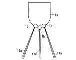
電界電離型イオン源では、図4に示すように、イオン11aは、チップ先端1aの微細構造、つまり先端の凸部1bを反映した方向に放出される。図4のように凸部1bが複数存在するとイオン11aは複数の方向に放出される。またイオン11aの各方向でのビームの広がり角は数度ときわめて狭い。(4) Improvement of ion beam performance In the field ionization ion source, as shown in FIG. 4, the
図7は従来の集束イオンビームの模式図である。イオン11aの放射方向は光軸40と異なっている。チップ1から放出されたイオン11aは集束レンズ電界6aに入射され、その後アライナ51によって照射方向を調整する。また調整機構20により集束レンズ中心を通るようにイオン11aを調整することが可能である。しかし、イオン11aの放射方向が集束イオンビーム光学系の中心軸である光軸40と異なっているために、イオン11aは集束レンズ電界6aに対し、斜めに入射することになる。レンズに斜めに入射すると収差が発生し、試料13上に収束するビーム形状を悪化させてしまう。また、チップ1から複数の方向にイオン11aが放出されると、外周方向のイオン11aはレンズの中心ではなく外側を通ることになる。外側を通ったイオン11aは集束レンズにより強く曲げられ、中心を通ったイオン11aと混ざり合ってしまう。そのため、この外周成分は中心成分に対するバックグランドの余計な成分となり、イオン11aの試料13上でビームの分布、つまりビームプロファイルが悪化してしまう。以上から、レンズ系のレンズ中心に、光軸に平行に、一つの方向のみのイオン11aを入射しなければならない。 FIG. 7 is a schematic diagram of a conventional focused ion beam. The radiation direction of the
図5は本発明に係る集束イオンビーム装置の模式図であり、集束レンズ電界6aよりもチップ1側のグランド部にガンアライメント電極9、第二のアパーチャ10を備える。チップ1からイオン11aが光軸40とは異なる方向に放出されてもガンアライメント電極9により光軸40と略平行に集束レンズ電界6aにイオン11aを入射することができる。また、第二のアパーチャ10により一つの方向に放出されたイオン11aのみを選択し集束レンズ電界6aの中心に入射することができる。以上により試料13表面の正確な位置に集束したイオンビーム11を照射することができる。 FIG. 5 is a schematic diagram of a focused ion beam apparatus according to the present invention, which includes a
また、第二のアパーチャ10は図6に示すように、径の異なる複数の開口部10aを有する。これによりイオンビーム11の照射軸に配置する開口部10aの径を変えることが可能であり、通過するイオンビーム11の電流量を調整することができる。 Moreover, the
さらに調整機構20はイオン銃部19をレンズ系に対して相対的に移動することが可能であり、イオン銃部19から放出されたイオンビーム11の照射位置を調整する。これによれば、イオンビーム11の照射位置を調整し、集束レンズ電界6aのレンズ中心に入射することができる。 Further, the adjusting
ガンアライメント電極9、第二のアパーチャ10はチップ1に対し、この順で配置することが好ましい。その理由はガンアライメント電極9がイオン源と遠くなると、調整機構20の移動距離が大きくなることと、偏向器に対してビームが軸外を通るので収差が大きくなり、ビーム径が悪化するためである。 The
本発明では調整機構20による平行移動と、ガンアライメント電極9による方向の調整を行ったが、他の構成として、イオン源直下に二段のアライメント電極を設け、ビームをチルト、シフトし、平行移動と方向調整を行っても良い。 In the present invention, parallel movement by the
またガンアライメント電極9には走査信号をいれ、アパーチャ上をスキャンできるようにすることでイオン源の位置探しを行っても良い。 Alternatively, a scanning signal may be input to the
第二のアパーチャ10は電気的に絶縁し、電流を測定可能とし、イオン源エミッション電流のモニターとして使用することも可能である。このモニター機能を利用し、引き出し電圧やガス流量を調整し、エミッション電流を一定に保つことも可能である。 The
(5)ガス銃
ガス銃18は、試料13表面にデポジション膜の原料ガス(例えば、フェナントレン、ナフタレンなどのカーボン系ガス、プラチナやタングステンなどの金属を含有する金属化合物ガスなど)を原料容器からノズルを通して供給する構成になっている。(5) Gas gun The
また、エッチング加工を行う場合は、エッチングガス(例えば、フッ化キセノン、塩素、ヨウ素、三フッ化塩素、一酸化フッ素、水など)を原料容器からノズルを通して供給することができる。 In the case of performing etching processing, an etching gas (for example, xenon fluoride, chlorine, iodine, chlorine trifluoride, fluorine monoxide, water, or the like) can be supplied from the raw material container through the nozzle.
<実施例1>
本実施形態のビーム調整方法を説明する。第二のアパーチャ10で径が一番大きい開口部10aをイオンビーム11の照射軸に配置する。チップ1からイオン銃部19からイオンビームを照射した状態で二次電子像を見ながら、調整機構20を操作してイオンビームが試料13に多く到達するイオン銃部19のレンズ系に対する位置を探す。試料13にイオンビームが多く到達するイオン銃部19の位置において、対物レンズ電極8の印加電圧を変化させ、電圧が変化しても二次電子像が動かないようにガンアライメント電極9の印加電圧を調整する。<Example 1>
The beam adjustment method of this embodiment will be described. The opening 10 a having the largest diameter in the
次に集束レンズ電極6の印加電圧を変化させ、電圧が変化しても二次電子像が動かないように調整機構20を操作してイオン銃部19の位置を調整する。 Next, the applied voltage of the focusing
次に第二のアパーチャ10で径の小さい開口部10aをイオンビーム11の照射軸に配置する。再度調整が必要な場合、上記の調整プロセスを再び行う。これによりチップ1の方向が試料13の表面に対してずれていても、集束レンズの中心付近にイオンビーム11を照射し、また余計な成分をアパーチャにより制限することで、試料13に形状の整ったビームプロファイルを有するイオンビーム11を照射することができる。 Next, an opening 10 a having a small diameter is arranged on the irradiation axis of the
<実施例2>
本実施形態の観察、加工方法を説明する。冷却装置24によって冷却されたチップ1にイオン源用ガスノズル2を介してヘリウムガスを供給し、チップ1にヘリウムガスを吸着させる。チップ1と引出電極4の間に電圧を供給して吸着したヘリウムガスをイオン化して、引出電極4の開口部からレンズ系に向けてイオン11aを射出する。ガンアライメント電極9で照射軸を偏向されたイオンビーム11のビーム中心部分は第二のアパーチャ10の開口部を通過して集束レンズの中心部に入射される。レンズ系で集束されたイオンビーム11は試料13の表面に照射される。試料13から発生した二次電子を検出器14で検出する。ここで検出器14は二次電子を検出する場合は二次電子検出器を用い、二次イオンを検出する場合は二次イオン検出器を用いることが好ましい。さらに反射イオンを検出する場合は反射イオン検出器を用いることが可能である。検出器14の検出信号とイオンビーム11を走査電極(図示せず)に入力する走査信号から制御部16内の画像形成部で二次電子像を形成する。これにより試料13表面を観察する。<Example 2>
The observation and processing method of this embodiment will be described. Helium gas is supplied to the
ガス銃18からエッチングガスを試料13表面に供給し、イオンビーム11を走査照射する。イオンビーム11が照射された領域において試料13がエッチングされ、局所的に加工することができる。 An etching gas is supplied from the
また、ガス銃18からデポジション膜の原料ガスを試料13表面に供給し、イオンビーム11を走査照射する。イオンビーム11が照射された領域においてデポジション膜が形成され、局所的に成膜することができる。 Further, the source gas of the deposition film is supplied from the
1…チップ
2…イオン源用ガスノズル
3…イオン源用ガス供給源
4…引出電極
5…カソード電極
6…集束レンズ電極
7…第一のアパーチャ
7a…開口部
8…対物レンズ電極
9…ガンアライメント
10…第二のアパーチャ
10a…開口部
11…イオンビーム
12…試料ステージ
13…試料
14…検出器
15…試料室
16…制御部
17…表示部
18…ガス銃
19…イオン銃部
20…調整機構
21…イオン発生室
24…冷却装置
25…ガス分子
27…電源DESCRIPTION OF
Claims (6)
Translated fromJapanese前記チップにガスを供給するガス供給部と、
前記チップとの間で電圧を印加し、前記チップ表面に吸着した前記ガスをイオン化してイオンを引き出す引出電極と、
前記イオンを試料に向けて加速させるカソード電極と、
を有する電界電離型イオン銃部と、
前記電界電離型イオン銃部から放出されたイオンビームの照射方向を調整するガンアライメント電極と、
前記試料に前記イオンビームを集束させるレンズ系と、
を有する集束イオンビーム装置。Needle-shaped tips,
A gas supply unit for supplying gas to the chip;
An extraction electrode that applies a voltage between the chip and ionizes the gas adsorbed on the chip surface to extract ions;
A cathode electrode for accelerating the ions toward the sample;
A field ionization ion gun having
A gun alignment electrode for adjusting the irradiation direction of the ion beam emitted from the field ionization type ion gun part;
A lens system for focusing the ion beam on the sample;
A focused ion beam apparatus.
Priority Applications (2)
| Application Number | Priority Date | Filing Date | Title |
|---|---|---|---|
| JP2010031605AJP2011171009A (en) | 2010-02-16 | 2010-02-16 | Focused ion beam device |
| US12/931,987US20110215256A1 (en) | 2010-02-16 | 2011-02-15 | Focused ion beam apparatus |
Applications Claiming Priority (1)
| Application Number | Priority Date | Filing Date | Title |
|---|---|---|---|
| JP2010031605AJP2011171009A (en) | 2010-02-16 | 2010-02-16 | Focused ion beam device |
Publications (1)
| Publication Number | Publication Date |
|---|---|
| JP2011171009Atrue JP2011171009A (en) | 2011-09-01 |
Family
ID=44530495
Family Applications (1)
| Application Number | Title | Priority Date | Filing Date |
|---|---|---|---|
| JP2010031605APendingJP2011171009A (en) | 2010-02-16 | 2010-02-16 | Focused ion beam device |
Country Status (2)
| Country | Link |
|---|---|
| US (1) | US20110215256A1 (en) |
| JP (1) | JP2011171009A (en) |
Cited By (1)
| Publication number | Priority date | Publication date | Assignee | Title |
|---|---|---|---|---|
| JP2014186894A (en)* | 2013-03-25 | 2014-10-02 | Hitachi High-Tech Science Corp | Conversing ion beam apparatus |
Families Citing this family (6)
| Publication number | Priority date | Publication date | Assignee | Title |
|---|---|---|---|---|
| JP5989959B2 (en)* | 2010-02-16 | 2016-09-07 | 株式会社日立ハイテクサイエンス | Focused ion beam device |
| JP2011210492A (en)* | 2010-03-29 | 2011-10-20 | Sii Nanotechnology Inc | Focused ion beam device |
| WO2013116787A1 (en)* | 2012-02-01 | 2013-08-08 | Muons, Inc. | Method and apparatus for lifetime extension of compact surface plasma source (csps) |
| JP6266458B2 (en)* | 2013-08-09 | 2018-01-24 | 株式会社日立ハイテクサイエンス | Iridium tip, gas field ion source, focused ion beam device, electron source, electron microscope, electron beam applied analyzer, ion electron composite beam device, scanning probe microscope, and mask correction device |
| US20240105421A1 (en)* | 2022-09-22 | 2024-03-28 | Applied Materials Israel Ltd. | Enhanced deposition rate by applying a negative voltage to a gas injection nozzle in fib systems |
| CN119958934B (en)* | 2025-02-23 | 2025-09-12 | 北京艾博智业离子技术有限公司 | An ion thinning instrument with adjustable focused ion gun |
Citations (3)
| Publication number | Priority date | Publication date | Assignee | Title |
|---|---|---|---|---|
| JPH04196407A (en)* | 1990-11-28 | 1992-07-16 | Fujitsu Ltd | Aligning method of focusing ion beam device |
| JPH07272652A (en)* | 1994-03-29 | 1995-10-20 | Jeol Ltd | Method of adjusting field-ionization gas phase ion source |
| JPH07335158A (en)* | 1994-06-14 | 1995-12-22 | Shimadzu Corp | Electron beam optical axis alignment device |
Family Cites Families (25)
| Publication number | Priority date | Publication date | Assignee | Title |
|---|---|---|---|---|
| US3740554A (en)* | 1972-04-13 | 1973-06-19 | Atomic Energy Commission | Multi-ampere duopigatron ion source |
| US3784858A (en)* | 1972-11-24 | 1974-01-08 | J Franks | Ion sources |
| US4085330A (en)* | 1976-07-08 | 1978-04-18 | Burroughs Corporation | Focused ion beam mask maker |
| JP2835097B2 (en)* | 1989-09-21 | 1998-12-14 | 株式会社東芝 | Correction method for charged beam astigmatism |
| GB9813327D0 (en)* | 1998-06-19 | 1998-08-19 | Superion Ltd | Apparatus and method relating to charged particles |
| KR100392039B1 (en)* | 1999-02-22 | 2003-07-22 | 가부시끼가이샤 도시바 | Ion implantation method and ion implantation equipment |
| JP3773398B2 (en)* | 1999-07-08 | 2006-05-10 | 日本電子株式会社 | Focused ion beam device |
| JP2001203150A (en)* | 2000-01-21 | 2001-07-27 | Nikon Corp | Hollow aperture, charged particle beam exposure apparatus, beam alignment method in charged particle beam exposure apparatus, method for adjusting charged particle dose, method for adjusting charged particle beam source, and method for manufacturing semiconductor device |
| US6768120B2 (en)* | 2001-08-31 | 2004-07-27 | The Regents Of The University Of California | Focused electron and ion beam systems |
| US20050061997A1 (en)* | 2003-09-24 | 2005-03-24 | Benveniste Victor M. | Ion beam slit extraction with mass separation |
| US7462848B2 (en)* | 2003-10-07 | 2008-12-09 | Multibeam Systems, Inc. | Optics for generation of high current density patterned charged particle beams |
| US8110814B2 (en)* | 2003-10-16 | 2012-02-07 | Alis Corporation | Ion sources, systems and methods |
| JP2006216396A (en)* | 2005-02-04 | 2006-08-17 | Hitachi High-Technologies Corp | Charged particle beam equipment |
| US7186992B2 (en)* | 2005-02-07 | 2007-03-06 | Hewlett-Packard Development Company, L.P. | Method of fabricating a polarizing layer on an interface |
| TWI323004B (en)* | 2005-12-15 | 2010-04-01 | Nuflare Technology Inc | Charged particle beam writing method and apparatus |
| US8314627B2 (en)* | 2006-10-13 | 2012-11-20 | Ricoh Company, Limited | Latent-image measuring device and latent-image carrier |
| JP5410975B2 (en)* | 2007-08-08 | 2014-02-05 | 株式会社日立ハイテクサイエンス | Composite focused ion beam apparatus and processing observation method using the same |
| EP2068345B1 (en)* | 2007-12-05 | 2016-07-20 | ICT Integrated Circuit Testing Gesellschaft für Halbleiterprüftechnik mbH | High resolution gas field ion column with reduced sample load |
| JP5086105B2 (en)* | 2008-01-07 | 2012-11-28 | 株式会社日立ハイテクノロジーズ | Gas field ion source |
| EP2088613B1 (en)* | 2008-02-08 | 2015-10-14 | ICT, Integrated Circuit Testing Gesellschaft für Halbleiterprüftechnik mbH | Use of a dual mode gas field ion source |
| US7994488B2 (en)* | 2008-04-24 | 2011-08-09 | Axcelis Technologies, Inc. | Low contamination, low energy beamline architecture for high current ion implantation |
| US20090314963A1 (en)* | 2008-06-24 | 2009-12-24 | Tel Epion Inc. | Method for forming trench isolation |
| US8664621B2 (en)* | 2008-09-15 | 2014-03-04 | Centre National De La Recherche Scientifique (C.N.R.S.) | Device for generating an ion beam with magnetic filter |
| EP2211366B1 (en)* | 2009-01-23 | 2011-10-19 | ICT, Integrated Circuit Testing Gesellschaft für Halbleiterprüftechnik mbH | High resolution gas field ion column |
| US20100200774A1 (en)* | 2009-02-09 | 2010-08-12 | Tel Epion Inc. | Multi-sequence film deposition and growth using gas cluster ion beam processing |
- 2010
- 2010-02-16JPJP2010031605Apatent/JP2011171009A/enactivePending
- 2011
- 2011-02-15USUS12/931,987patent/US20110215256A1/ennot_activeAbandoned
Patent Citations (3)
| Publication number | Priority date | Publication date | Assignee | Title |
|---|---|---|---|---|
| JPH04196407A (en)* | 1990-11-28 | 1992-07-16 | Fujitsu Ltd | Aligning method of focusing ion beam device |
| JPH07272652A (en)* | 1994-03-29 | 1995-10-20 | Jeol Ltd | Method of adjusting field-ionization gas phase ion source |
| JPH07335158A (en)* | 1994-06-14 | 1995-12-22 | Shimadzu Corp | Electron beam optical axis alignment device |
Cited By (1)
| Publication number | Priority date | Publication date | Assignee | Title |
|---|---|---|---|---|
| JP2014186894A (en)* | 2013-03-25 | 2014-10-02 | Hitachi High-Tech Science Corp | Conversing ion beam apparatus |
Also Published As
| Publication number | Publication date |
|---|---|
| US20110215256A1 (en) | 2011-09-08 |
Similar Documents
| Publication | Publication Date | Title |
|---|---|---|
| US7968855B2 (en) | Dual mode gas field ion source | |
| US7772564B2 (en) | Particle-optical apparatus equipped with a gas ion source | |
| JP5194154B2 (en) | Gas field ionization ion source, scanning charged particle microscope | |
| US8822945B2 (en) | Focused ion beam apparatus | |
| JP4982161B2 (en) | Gas field ion source and scanning charged particle microscope | |
| JP5989959B2 (en) | Focused ion beam device | |
| JP2011171009A (en) | Focused ion beam device | |
| US9305746B2 (en) | Pre-aligned nozzle/skimmer | |
| JP2016001606A (en) | Composite focused ion beam device, and sample processing method using the same | |
| JP6433515B2 (en) | Mirror ion microscope and ion beam control method | |
| JP5432028B2 (en) | Focused ion beam device, tip end structure inspection method, and tip end structure regeneration method | |
| US8124941B2 (en) | Increasing current in charged particle sources and systems | |
| US8558192B2 (en) | Gas delivery system with voltage gradient for an ion microscope | |
| US11764036B2 (en) | Operating a gas supply device for a particle beam device | |
| TWI729241B (en) | Focused ion beam device | |
| JP5592136B2 (en) | Chip tip structure inspection method | |
| US10971329B2 (en) | Field ionization source, ion beam apparatus, and beam irradiation method | |
| CN115346850A (en) | Particle beam device with deflection unit | |
| JP6116303B2 (en) | Focused ion beam device | |
| JP5448971B2 (en) | Charged particle beam apparatus, chip regeneration method, and sample observation method | |
| JP7535195B2 (en) | Ion beam device and emitter tip processing method | |
| JP2011233509A (en) | Emitter of field ionization type ion source, focused ion beam device and focused ion beam irradiation method |
Legal Events
| Date | Code | Title | Description |
|---|---|---|---|
| RD03 | Notification of appointment of power of attorney | Free format text:JAPANESE INTERMEDIATE CODE: A7423 Effective date:20121122 | |
| A621 | Written request for application examination | Free format text:JAPANESE INTERMEDIATE CODE: A621 Effective date:20130208 | |
| A977 | Report on retrieval | Free format text:JAPANESE INTERMEDIATE CODE: A971007 Effective date:20131216 | |
| A131 | Notification of reasons for refusal | Free format text:JAPANESE INTERMEDIATE CODE: A131 Effective date:20131224 | |
| A521 | Request for written amendment filed | Free format text:JAPANESE INTERMEDIATE CODE: A523 Effective date:20140224 | |
| A131 | Notification of reasons for refusal | Free format text:JAPANESE INTERMEDIATE CODE: A131 Effective date:20140708 | |
| A02 | Decision of refusal | Free format text:JAPANESE INTERMEDIATE CODE: A02 Effective date:20141111 |