JP2011161603A - Power tool using a plurality of battery packs as power source - Google Patents
Power tool using a plurality of battery packs as power sourceDownload PDFInfo
- Publication number
- JP2011161603A JP2011161603AJP2010029506AJP2010029506AJP2011161603AJP 2011161603 AJP2011161603 AJP 2011161603AJP 2010029506 AJP2010029506 AJP 2010029506AJP 2010029506 AJP2010029506 AJP 2010029506AJP 2011161603 AJP2011161603 AJP 2011161603A
- Authority
- JP
- Japan
- Prior art keywords
- battery pack
- voltage
- adapter
- circuit
- pack
- Prior art date
- Legal status (The legal status is an assumption and is not a legal conclusion. Google has not performed a legal analysis and makes no representation as to the accuracy of the status listed.)
- Granted
Links
- 230000001131transforming effectEffects0.000claims2
- HBBGRARXTFLTSG-UHFFFAOYSA-NLithium ionChemical compound[Li+]HBBGRARXTFLTSG-UHFFFAOYSA-N0.000description21
- 229910001416lithium ionInorganic materials0.000description21
- 238000012986modificationMethods0.000description10
- 230000004048modificationEffects0.000description10
- 238000005516engineering processMethods0.000description8
- 238000010586diagramMethods0.000description6
- 238000001514detection methodMethods0.000description5
- 230000005856abnormalityEffects0.000description2
- 208000019300CLIPPERSDiseases0.000description1
- 235000005273Canna coccineaNutrition0.000description1
- 240000008555Canna flaccidaSpecies0.000description1
- 230000005540biological transmissionEffects0.000description1
- 230000015556catabolic processEffects0.000description1
- 208000021930chronic lymphocytic inflammation with pontine perivascular enhancement responsive to steroidsDiseases0.000description1
- 238000004891communicationMethods0.000description1
- 230000007423decreaseEffects0.000description1
- 230000000694effectsEffects0.000description1
- 238000010413gardeningMethods0.000description1
- 238000005555metalworkingMethods0.000description1
- 238000000034methodMethods0.000description1
- 238000012544monitoring processMethods0.000description1
- 238000013021overheatingMethods0.000description1
Images


Classifications
- H—ELECTRICITY
- H02—GENERATION; CONVERSION OR DISTRIBUTION OF ELECTRIC POWER
- H02J—CIRCUIT ARRANGEMENTS OR SYSTEMS FOR SUPPLYING OR DISTRIBUTING ELECTRIC POWER; SYSTEMS FOR STORING ELECTRIC ENERGY
- H02J7/00—Circuit arrangements for charging or depolarising batteries or for supplying loads from batteries
- H02J7/0063—Circuit arrangements for charging or depolarising batteries or for supplying loads from batteries with circuits adapted for supplying loads from the battery
- A—HUMAN NECESSITIES
- A47—FURNITURE; DOMESTIC ARTICLES OR APPLIANCES; COFFEE MILLS; SPICE MILLS; SUCTION CLEANERS IN GENERAL
- A47L—DOMESTIC WASHING OR CLEANING; SUCTION CLEANERS IN GENERAL
- A47L9/00—Details or accessories of suction cleaners, e.g. mechanical means for controlling the suction or for effecting pulsating action; Storing devices specially adapted to suction cleaners or parts thereof; Carrying-vehicles specially adapted for suction cleaners
- A47L9/28—Installation of the electric equipment, e.g. adaptation or attachment to the suction cleaner; Controlling suction cleaners by electric means
- A47L9/2868—Arrangements for power supply of vacuum cleaners or the accessories thereof
- A47L9/2884—Details of arrangements of batteries or their installation
- B—PERFORMING OPERATIONS; TRANSPORTING
- B25—HAND TOOLS; PORTABLE POWER-DRIVEN TOOLS; MANIPULATORS
- B25F—COMBINATION OR MULTI-PURPOSE TOOLS NOT OTHERWISE PROVIDED FOR; DETAILS OR COMPONENTS OF PORTABLE POWER-DRIVEN TOOLS NOT PARTICULARLY RELATED TO THE OPERATIONS PERFORMED AND NOT OTHERWISE PROVIDED FOR
- B25F5/00—Details or components of portable power-driven tools not particularly related to the operations performed and not otherwise provided for
- H—ELECTRICITY
- H02—GENERATION; CONVERSION OR DISTRIBUTION OF ELECTRIC POWER
- H02J—CIRCUIT ARRANGEMENTS OR SYSTEMS FOR SUPPLYING OR DISTRIBUTING ELECTRIC POWER; SYSTEMS FOR STORING ELECTRIC ENERGY
- H02J7/00—Circuit arrangements for charging or depolarising batteries or for supplying loads from batteries
- H02J7/0029—Circuit arrangements for charging or depolarising batteries or for supplying loads from batteries with safety or protection devices or circuits
- H02J7/00309—Overheat or overtemperature protection
- H—ELECTRICITY
- H02—GENERATION; CONVERSION OR DISTRIBUTION OF ELECTRIC POWER
- H02J—CIRCUIT ARRANGEMENTS OR SYSTEMS FOR SUPPLYING OR DISTRIBUTING ELECTRIC POWER; SYSTEMS FOR STORING ELECTRIC ENERGY
- H02J7/00—Circuit arrangements for charging or depolarising batteries or for supplying loads from batteries
- H02J7/0047—Circuit arrangements for charging or depolarising batteries or for supplying loads from batteries with monitoring or indicating devices or circuits
- H02J7/0048—Detection of remaining charge capacity or state of charge [SOC]
- H—ELECTRICITY
- H02—GENERATION; CONVERSION OR DISTRIBUTION OF ELECTRIC POWER
- H02M—APPARATUS FOR CONVERSION BETWEEN AC AND AC, BETWEEN AC AND DC, OR BETWEEN DC AND DC, AND FOR USE WITH MAINS OR SIMILAR POWER SUPPLY SYSTEMS; CONVERSION OF DC OR AC INPUT POWER INTO SURGE OUTPUT POWER; CONTROL OR REGULATION THEREOF
- H02M1/00—Details of apparatus for conversion
- H02M1/10—Arrangements incorporating converting means for enabling loads to be operated at will from different kinds of power supplies, e.g. from AC or DC
- H—ELECTRICITY
- H02—GENERATION; CONVERSION OR DISTRIBUTION OF ELECTRIC POWER
- H02J—CIRCUIT ARRANGEMENTS OR SYSTEMS FOR SUPPLYING OR DISTRIBUTING ELECTRIC POWER; SYSTEMS FOR STORING ELECTRIC ENERGY
- H02J7/00—Circuit arrangements for charging or depolarising batteries or for supplying loads from batteries
- H02J7/0029—Circuit arrangements for charging or depolarising batteries or for supplying loads from batteries with safety or protection devices or circuits
- H02J7/00306—Overdischarge protection
Landscapes
- Engineering & Computer Science (AREA)
- Power Engineering (AREA)
- Mechanical Engineering (AREA)
- Secondary Cells (AREA)
- Battery Mounting, Suspending (AREA)
- Portable Power Tools In General (AREA)
- Charge And Discharge Circuits For Batteries Or The Like (AREA)
Abstract
Translated fromJapaneseDescription
Translated fromJapanese本発明は、複数のバッテリパックを電源とする電動工具に関する。 The present invention relates to an electric tool using a plurality of battery packs as a power source.
特許文献1に、二つのバッテリパックを電源とする電動工具が開示されている。この電動工具では、二つのバッテリパックが直列に接続されており、高電圧でモータが駆動される構成となっている。それにより、一つのバッテリパックを電源とするものに比べて、重作業に使用可能な高い出力を発揮することができる。
現在、バッテリパックには、一又は複数の電池セルだけでなく、集積回路が内蔵されており、電池セルの電圧や温度等の測定が行われている。また、一部のバッテリパックでは、集積回路にCPUが搭載されており、各種の制御プログラムが実行されるものも多い。バッテリパックの集積回路は、電動工具に内蔵された制御回路や、充電装置に内蔵された制御回路と電気的に接続され、それらの制御回路との間で信号電圧の入出力を行うことができる。例えば、バッテリパックの集積回路は、電池セルの測定電圧が許容値を下回った時に、動作停止を要求する信号電圧を出力する。出力された信号電圧は、電動工具の制御回路に入力され、電動工具の制御回路は、当該信号電圧を受けて、モータの駆動を直ちに停止することができる。このように、バッテリパックの充電レベルを監視し、電動工具の動作を自動的に停止することで、バッテリパックの過放電を防止することができる。このような機能は、オートストップ機能、あるいは単にオートストップと称される。 Currently, not only one or a plurality of battery cells but also an integrated circuit is built in the battery pack, and the voltage and temperature of the battery cells are measured. In some battery packs, a CPU is mounted on an integrated circuit, and various control programs are often executed. The integrated circuit of the battery pack is electrically connected to a control circuit built in the electric tool or a control circuit built in the charging device, and can input / output a signal voltage to / from these control circuits. . For example, the integrated circuit of the battery pack outputs a signal voltage for requesting the operation stop when the measured voltage of the battery cell falls below an allowable value. The output signal voltage is input to the control circuit of the electric tool, and the control circuit of the electric tool can immediately stop driving the motor upon receiving the signal voltage. In this way, overcharging of the battery pack can be prevented by monitoring the charge level of the battery pack and automatically stopping the operation of the power tool. Such a function is called an auto-stop function or simply an auto-stop.
上記に関して、二つのバッテリパックを電源とする電動工具では、それぞれのバッテリパックの集積回路を電動工具の制御回路へ電気的に接続し、それぞれの集積回路から出力される信号電圧を電動工具の制御回路へ入力する必要がある。しかしながら、直列に接続された二つのバッテリパックでは、集積回路の基準電圧(接地電圧)が互いに相違することになり、集積回路が出力する信号電圧のレベルも大きく相違する With regard to the above, in an electric tool using two battery packs as power sources, the integrated circuit of each battery pack is electrically connected to the control circuit of the electric tool, and the signal voltage output from each integrated circuit is controlled by the electric tool. It is necessary to input to the circuit. However, in two battery packs connected in series, the reference voltage (ground voltage) of the integrated circuit is different from each other, and the level of the signal voltage output from the integrated circuit is also greatly different.
例えば、電圧が18ボルトのバッテリパックを二つ、直列に接続したと仮定する。この場合、低電圧側に位置する一方のバッテリパックでは、集積回路の基準電圧は電動工具の制御回路と同じゼロボルトになり、高電圧側に位置する他方のバッテリパックでは、電動工具の制御回路をゼロボルトとした場合、集積回路の基準電圧は18ボルトになる。従って、電動工具の制御回路へ信号を出力する場合、一方のバッテリパックの集積回路は、ローレベルの信号電圧としてゼロボルトを出力することになり、他方のバッテリパックの集積回路は、ローレベルの信号電圧として18ボルトを出力することになる。電動工具の制御回路は、通常、その基準電圧がゼロボルトであることから、他方のバッテリパックから出力される信号電圧を、高圧すぎるために入力することができない。 For example, assume that two battery packs having a voltage of 18 volts are connected in series. In this case, in one battery pack located on the low voltage side, the reference voltage of the integrated circuit is the same zero volt as the control circuit of the electric tool, and in the other battery pack located on the high voltage side, the control circuit of the electric tool is With zero volts, the integrated circuit reference voltage is 18 volts. Therefore, when a signal is output to the control circuit of the power tool, the integrated circuit of one battery pack outputs zero volt as the low level signal voltage, and the integrated circuit of the other battery pack outputs the low level signal. As a voltage, 18 volts is output. Since the reference voltage of the power tool control circuit is normally zero volts, the signal voltage output from the other battery pack cannot be input because it is too high.
上記のように、複数のバッテリパックを電源とする電動工具において、複数のバッテリパックを直列に接続した場合、それぞれの集積回路から出力される信号電圧を、電動工具の制御回路へそのまま入力することはできなくなる。あるいは、電動工具の制御回路が出力する信号電圧を、それぞれのバッテリパックの集積回路へそのまま入力することもできなくなる。その結果、バッテリパックの集積回路と電動工具の制御回路の間で通信することが不可能となり、例えば上述したオートストップ機能を採用することができなくなってしまう。 As described above, when a plurality of battery packs are connected in series in a power tool that uses a plurality of battery packs as power sources, the signal voltage output from each integrated circuit is directly input to the control circuit of the power tool. Can not. Alternatively, the signal voltage output from the control circuit of the power tool cannot be directly input to the integrated circuit of each battery pack. As a result, it becomes impossible to communicate between the integrated circuit of the battery pack and the control circuit of the power tool, and for example, the above-described auto-stop function cannot be employed.
本技術では、上記の問題を回避するために、バッテリパックの集積回路と電動工具の制御回路の間にレベルシフタを設け、バッテリパックの集積回路が出力する信号電圧のレベルを、電動工具の制御回路が許容するレベルに変圧する。それにより、複数のバッテリパックが直列に接続された場合でも、それぞれの集積回路から出力される信号電圧を、電動工具の制御回路へ入力することができる。バッテリパックの集積回路と電動工具の制御回路の間で通信することが可能となり、例えば上述したオートストップ機能を採用することができる。 In the present technology, in order to avoid the above problem, a level shifter is provided between the integrated circuit of the battery pack and the control circuit of the electric power tool, and the level of the signal voltage output from the integrated circuit of the battery pack is determined by the control circuit of the electric power tool. Transform to a level acceptable by Thereby, even when a plurality of battery packs are connected in series, the signal voltage output from each integrated circuit can be input to the control circuit of the power tool. Communication between the integrated circuit of the battery pack and the control circuit of the power tool can be performed, and for example, the above-described auto-stop function can be employed.
本技術の一実施形態として、電動工具は、複数のバッテリパックを直列に接続して電源とすることが好ましい。各々のバッテリパックは、信号電圧を出力する集積回路を有しており、電動工具は、各々のバッテリパックの集積回路から出力される信号電圧をそれぞれ入力する制御回路を備えている。さらに、この電動工具は、少なくとも一つのバッテリパックの集積回路と制御回路の間に設けられ、バッテリパックの集積回路が出力する信号電圧のレベルを、電動工具の制御回路が許容するレベルに変圧するレベルシフタを備えている。 As one embodiment of the present technology, it is preferable that the power tool be a power source by connecting a plurality of battery packs in series. Each battery pack has an integrated circuit that outputs a signal voltage, and the power tool includes a control circuit that inputs a signal voltage output from the integrated circuit of each battery pack. Further, the power tool is provided between the integrated circuit and the control circuit of at least one battery pack, and transforms the level of the signal voltage output from the integrated circuit of the battery pack to a level allowed by the control circuit of the power tool. A level shifter is provided.
この電動工具では、バッテリパックの集積回路と電動工具の制御回路の間で通信することが可能となり、例えば上述したオートストップ機能を含め、バッテリパックのダメージを防止する様々な機能を採用することができる。 In this electric power tool, it becomes possible to communicate between the integrated circuit of the battery pack and the control circuit of the electric power tool. For example, various functions for preventing damage to the battery pack can be adopted including the above-described auto-stop function. .
本技術の一実施形態である電動工具は、金工用の電動工具であってもよいし、木工用の電動工具であってもよいし、石工用の電動工具であってもよいし、園芸用の電動工具であってもよい。具体的には、電動ドリル、電動ドライバ、電動レンチ、電動グラインダ、電動マルノコ、電動レシプロソー、電動ジグソー、電動ハンマ、電動カッター、電動チェーンソー、電動カンナ、電動釘打ち機(鋲打ち機を含む)、電動ヘッジトリマ、電動芝生バリカン、電動芝刈機、電動刈払機、電動ブロワー、電動クリーナ等が挙げられる。 The electric tool according to an embodiment of the present technology may be a metalworking power tool, a woodworking power tool, a masonry power tool, or a gardening tool. The electric tool may be used. Specifically, electric drill, electric driver, electric wrench, electric grinder, electric marnoco, electric reciprocating saw, electric jigsaw, electric hammer, electric cutter, electric chainsaw, electric canna, electric nailer (including a hammer) Examples include an electric hedge trimmer, an electric lawn clipper, an electric lawn mower, an electric brush cutter, an electric blower, and an electric cleaner.
本発明の一実施形態では、各々のバッテリパックが複数のリチウムイオン電池セルを有し、その公称電圧が7.0ボルト以上であることが好ましい。リチウムイオン電池セルは、過放電や過熱によって受けるダメージが大きい。この点において、本技術によれば、リチウムイオン電池セルのダメージを防止する各種の機能を採用することができ、各々のバッテリパックを長期に亘って使用することが可能となる。 In one embodiment of the present invention, each battery pack preferably has a plurality of lithium ion battery cells, and the nominal voltage thereof is preferably 7.0 volts or more. Lithium ion battery cells are greatly damaged by overdischarge and overheating. In this regard, according to the present technology, various functions for preventing damage to the lithium ion battery cell can be employed, and each battery pack can be used over a long period of time.
現在、複数のリチウムイオン電池セルを内蔵し、公称電圧が18ボルトのバッテリパックと、そのバッテリパックを利用する定格電圧が18ボルトの電動工具が多く利用されている。本発明の一実施形態では、そのような公称電圧が18ボルトのバッテリパックを複数利用し、定格電圧が36ボルト以上の電動工具を駆動することが好ましい。それにより、ユーザは、既に保有するバッテリパックによって、より高出力の電動工具を使用することが可能となる。即ち、ユーザは、公称電圧が36ボルト以上のバッテリパックを新たに用意する必要がない。既に保有する公称電圧が18ボルトのバッテリパックを、定格電圧が18ボルトの電動工具だけでなく、定格電圧が36ボルト以上の電動工具にも、有効に利用することができる。 Currently, a battery pack having a plurality of lithium ion battery cells and having a nominal voltage of 18 volts and a power tool having a rated voltage of 18 volts using the battery pack are widely used. In one embodiment of the present invention, it is preferable to use a plurality of such battery packs having a nominal voltage of 18 volts and drive a power tool having a rated voltage of 36 volts or more. Thereby, the user can use a higher-output power tool with the battery pack already held. That is, the user does not need to prepare a new battery pack having a nominal voltage of 36 volts or more. The battery pack having a nominal voltage of 18 volts already in use can be effectively used not only for a power tool having a rated voltage of 18 volts but also for a power tool having a rated voltage of 36 volts or more.
リチウムイオン電池セルの公称電圧は3.6ボルトであることから、公称電圧が18ボルトのバッテリパックは、少なくとも、直列に接続された五本のリチウムイオン電池セルを有している。ここで、公称電圧が18ボルトのバッテリパックは、五本のリチウムイオン電池セルだけでなく、例えば十本のリチウムイオン電池セルを有することもできる。この場合、十本のリチウムイオン電池セルは、二本ずつが並列に接続されて五組のセル群を形成し、その五組のセル群が直列に接続されることで、36ボルトの電圧を出力する。同様にして、公称電圧が18ボルトのバッテリパックは、15又はそれ以上の本数のリチウムイオン電池セルを有することもできる。リチウムイオン電池セルの本数を多くするほど、バッテリパックの容量を大きくすることができるとともに、各々のリチウムイオン電池セルに流れる電流を小さくすることができる。 Since the nominal voltage of the lithium ion battery cell is 3.6 volts, the battery pack having a nominal voltage of 18 volts has at least five lithium ion battery cells connected in series. Here, the battery pack having a nominal voltage of 18 volts can have, for example, ten lithium ion battery cells as well as five lithium ion battery cells. In this case, ten lithium ion battery cells are connected in parallel to form five cell groups, and the five cell groups are connected in series, so that a voltage of 36 volts can be obtained. Output. Similarly, a battery pack with a nominal voltage of 18 volts can have 15 or more lithium ion battery cells. As the number of lithium ion battery cells is increased, the capacity of the battery pack can be increased, and the current flowing through each lithium ion battery cell can be reduced.
図1は、本技術の一実施形態に係る製品群を示している。図1に示すように、この製品群には、二種類のバッテリパック10、30と、三種類の電動工具50、70、100と、二種類のアダプタ200、300が含まれている。ここで、アダプタ200、300は、単一のバッテリパック30を電源とする電動工具70の本体72に、複数のバッテリパック10を電気的に接続するための装置である。 FIG. 1 shows a product group according to an embodiment of the present technology. As shown in FIG. 1, this product group includes two types of battery packs 10, 30, three types of
二種類のバッテリパック10、30のうち、一種類のバッテリパック10は、公称電圧が18ボルトのバッテリパックであり、他の一種類のバッテリパック30は、公称電圧が36ボルトのバッテリパックである。以下では、便宜上、公称電圧が18ボルトのバッテリパック10を低電圧バッテリパック10と称し、公称電圧が36ボルトのバッテリパック30を高電圧バッテリパック30と称する。 Of the two types of battery packs 10, 30, one type of
低電圧バッテリパック10は、直列に接続された五本のリチウムイオン電池セルを有している。一方、高電圧バッテリパック30は、直列に接続された十本のリチウムイオン電池セルを内蔵している。二種類のバッテリパック10、30は、再充電可能なバッテリパックであり、電動工具50、70、100の電源として用いられた後に、充電器(図示省略)によって再充電することができる。また、二種類のバッテリパック10、30は、いわゆるスライド式のバッテリパックであり、電動工具50、70、100や充電器にスライドしながら取り付けられる。なお、これら二種類のバッテリパック10、30は、既に実用化されており、特に、公称電圧が18ボルトである低電圧バッテリパック10は、一般的に広く普及している。 The low
ここで、低電圧バッテリパック10は、五本のリチウムイオン電池セルだけでなく、例えば十本のリチウムイオン電池セルを内蔵することもできる。この場合、十本のリチウムイオン電池セルは、二本ずつが並列に接続されて五組のセル群を形成し、その五組のセル群が直列に接続されることで、18ボルトの電圧を出力する。同様に、高電圧バッテリパック30は、十本のリチウムイオン電池セルだけでなく、例えば二十本のリチウムイオン電池セルを内蔵することもできる。この場合、二十本のリチウムイオン電池セルは、二本ずつが並列に接続されて十組のセル群を形成し、その十組のセル群が直列に接続されることで、36ボルトの電圧を出力する。 Here, the low
三種類の電動工具50、70、100のうち、一種類の電動工具50は、定格電圧が18ボルトの電動工具であり、他の二種類の電動工具70、100は、定格電圧が36ボルトの電動工具である。以下では、便宜上、定格電圧が18ボルトの電動工具50を低電圧電動工具50と称し、定格電圧が36ボルトの電動工具70、100を高電圧電動工具70、100と称する。 Of the three types of
図17、図18に示すように、低電圧電動工具50は、一つの低電圧バッテリパック10を電源とする電動工具である。この低電圧電動工具50は、一例ではあるが、電動インパクトドライバであり、メインスイッチ58の操作に応じて工具チャック54を駆動する。工具チャック54には、工具であるドライバビットを取り付けることができる。一つの低電圧バッテリパック10を電源とする低電圧電動工具50は、既に実用化されており、公称電圧が18ボルトの低電圧バッテリパック10とともに広く普及している。 As shown in FIGS. 17 and 18, the low-voltage
低電圧電動工具50の本体52には、一つのパック取付部60が設けられている。パック取付部60は、低電圧バッテリパック10が着脱可能であり、低電圧バッテリパック10をスライド可能に受け入れる。パック取付部60は、一対のレール62、正極入力端子64a、負極入力端子64b、ロック受入穴68を有している。 The
一方、図19に示すように、低電圧バッテリパック10には、パック取付部60にスライド挿入されるコネクタ部20が設けられている。コネクタ部20には、一対のレール22、正極出力端子24a、負極出力端子24b、オートストップ端子26が設けられている。低電圧バッテリパック10をパック取付部60に取り付けると、低電圧バッテリパック10の正極出力端子24aが本体52の正極入力端子64aに接続され、低電圧バッテリパック10の負極出力端子24bが本体52の負極入力端子64bに接続される。それにより、低電圧バッテリパック10は、低電圧電動工具50の本体52へ電気的に接続される。また、低電圧バッテリパック10は、パック取付部60のロック受入穴68に係合し、低電圧バッテリパック10をパック取付部60に固定するロック部材12を有している。このロック部材12による固定は、ロック解除ボタン14によって解除することができる。 On the other hand, as shown in FIG. 19, the low
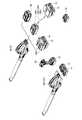
次に、二種類の高電圧電動工具70、100について説明する。二種類の高電圧電動工具70、100のうち、一方の高電圧電動工具70は、一つの高電圧バッテリパック30を電源とする電動工具である。図20、図21、図22を参照し、この高電圧電動工具70について説明する。この高電圧電動工具70は、一例ではあるが、電動ブロワーであり、メインスイッチ78への操作に応じて、本体72に内蔵された送風ファンを駆動する。電動ブロワー70は、園芸用の電動工具の一種であり、ノズル73の先端73aから吹き出す空気によって、例えば落葉を吹き集めることができる。定格電圧が36ボルトの高電圧電動工具70は、公称電圧が36ボルトの高電圧バッテリパック30とともに、既に実用化されている。 Next, two types of high voltage
高電圧電動工具70の本体72には、一つのパック取付部80が設けられている。パック取付部80は、高電圧バッテリパック30が着脱可能であり、高電圧バッテリパック30をスライド可能に受け入れる。パック取付部80は、一対のレール82、正極入力端子84a、負極入力端子84b、ロック受入穴88を有している。 The
一方、高電圧バッテリパック30には、パック取付部80にスライド挿入されるコネクタ部40が設けられている。コネクタ部40には、一対のレール42、正極出力端子44a、負極出力端子44b、オートストップ端子46が設けられている。高電圧バッテリパック30をパック取付部80に取り付けると、高電圧バッテリパック30の正極出力端子44aが、パック取付部80の正極入力端子84aに接続され、高電圧バッテリパック30の負極出力端子44bが、パック取付部80の負極入力端子84bに接続される。それにより、高電圧バッテリパック30は、高電圧電動工具70の本体72へ電気的に接続される。また、高電圧バッテリパック30は、パック取付部80のロック受入穴88に係合し、高電圧バッテリパック30をパック取付部80に固定するロック部材32を有している。このロック部材32による固定は、ロック解除ボタン34によって解除することができる。 On the other hand, the high
ここで、低電圧バッテリパック10と高電圧バッテリパック30との間で、コネクタ部20、40の構造は基本的に類似している。しかしながら、両者の間でコネクタ部20、40の大きさが互いに異なるため、低電圧バッテリパック10を高電圧電動工具70のパック取付部80に取り付けることはできず、高電圧バッテリパック30を低電圧電動工具50のパック取付部60に取り付けることもできない。 Here, between the low-
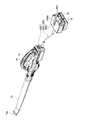
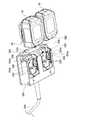
二種類の高電圧電動工具70、100のうち、他方の高電圧電動工具100は、二つの低電圧バッテリパック10を電源とする電動工具である。図2、図3、図4を参照し、この高電圧電動工具100について説明する。この高電圧電動工具100は、一例ではあるが、電動ブロワーであり、メインスイッチ108への操作に応じて、本体102に内蔵された送風ファンを駆動する。この電動ブロワー100は、その機能や用途において、先に説明した電動ブロワー70と基本的に同じものである。 Of the two types of high-voltage
高電圧電動工具100の本体102には、二つのパック取付部130が設けられている。各々のパック取付部130は、一つの低電圧バッテリパック10が着脱可能であり、低電圧バッテリパック10をスライド可能に受け入れる。パック取付部130は、一対のレール132、正極入力端子134a、負極入力端子134b、ロック受入穴138を有している。このパック取付部130は、その構造において、先に説明した低電圧電動工具50のパック取付部60と実質的に等しい。二つのパック取付部130は、本体102の後部に並んで配置されており、低電圧バッテリパック10が同一方向からそれぞれ挿入される。二つのパック取付部130に取り付けられた二つの低電圧バッテリパック10は、直列に接続され、略36ボルトの電圧で本体102へ電力を供給する。 Two
高電圧電動工具100の本体102には、二つの表示器160が設けられている。二つの表示器160は、二つのパック取付部130の上部にそれぞれ位置している。各々の表示器160は、一例ではあるが、発光ダイオードである。一方の表示器160は、一方のパック取付部130に取り付けられた低電圧バッテリパック10の充電レベルを表示し、他方の表示器160は、他方のパック取付部130に取り付けられた低電圧バッテリパック10の状態を表示する。各々の表示器160は、対応する低電圧バッテリパック10の充電レベルを表示することができ、特に、その充電レベルが再充電を必要とするレベルに達した時に、発光ダイオードを点灯させることができる。なお、表示器160は、対応する低電圧バッテリパック10の充電レベルを、少なくとも二段階に表示することも好ましい。あるいは、表示器160が、対応する低電圧バッテリパック10の充電レベルに代えて、あるいは、充電レベルとともに、対応する低電圧バッテリパック10の温度異常を表示することも好ましい。 Two
図2に示すように、二つの表示器160は、高電圧電動工具100の後面102aに並んで配置されており、その表示方向(即ち、発光ダイオードの発光方向)は同じ方向を向いている。従って、ユーザは、二つの表示器160を同時に視認し、二つの低電圧バッテリパック10の充電レベルを同時に把握することができる。また、それぞれの表示器160は、対応するパック取付部130の上方に配置されている。従って、例えば高電圧電動工具100が突然に停止した場合に、どちらの低電圧バッテリパック10に問題があるのかを、ユーザは直ちに判断することができる。なお、二つの表示器160は、後面102aに限られず、ユーザが同時に視認可能な他の位置へ配置することもできる。この場合、二つの表示器160が同一平面に配置されていると、ユーザは二つの表示器160を様々な方向から同時に視認することができる。 As shown in FIG. 2, the two
ここで、表示器160は、各々の低電圧バッテリパック10に設けることもできる。先に説明したように、二つのパック取付部130は、並んで配置されているとともに、低電圧バッテリパック10を同一方向から受け入れる。従って、二つの低電圧バッテリパック10を本体102に取り付けた時に、それらの二つの表示器160は、同一平面内に並んで位置するとともに、その表示方向も同じ方向を向くことになる。その結果、ユーザは、二つの表示器160を様々な方向から同時に視認することができる。 Here, the
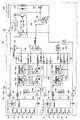
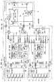
次に、図5を参照し、二つの低電圧バッテリパック10を電源とする高電圧電動工具100の電気的な構成について説明する。低電圧バッテリパック10は、直列に接続された五本の電池セル16と、バッテリコントローラ18を備えている。各々の電池セル16は、リチウムイオン電池セルであり、その公称電圧は3.6ボルトである。直列に接続された五本の電池セル16は、正極出力端子24aと負極出力端子24bに接続されており、両端子24a、24bから略18ボルトの電圧で電力を放電することができる。図5に示すように、上段に位置する低電圧バッテリパック10の負極出力端子24bは、その下段に位置する低電圧バッテリパック10の正極出力端子24aと電気的に接続される。それにより、二つの低電圧バッテリパック10は、直列に接続され、略36ボルトの電圧で本体102へ電力を供給する。 Next, with reference to FIG. 5, the electrical configuration of the high-
バッテリコントローラ18は、CPUを搭載した集積回路であり、記憶している各種のプログラムを実行することができる。また、バッテリコントローラ18は、各々の電池セル16と電気的に接続されており、各々の電池セル16の電圧を測定することができる。バッテリコントローラ18は、測定された各々の電池セル16の電圧に基づいて、各々の電池セル16の充電レベルを判定し、電池セル16の再充電が必要であると判断した時に、放電保護信号(オートストップ信号とも称される)をオートストップ端子26へ出力する。ここで、放電保護信号はハイインピーダンスを示す信号である。 The battery controller 18 is an integrated circuit on which a CPU is mounted, and can execute various stored programs. Moreover, the battery controller 18 is electrically connected to each
一方、本体102は、工具(ここでは送風ファン)を駆動するモータ176を備えている。モータ176には、メインスイッチ178を介して、二つの低電圧バッテリパック10が直列に接続される。また、本体102は、速度調節回路190、パワーFET194、ゲート制御トランジスタ192、分圧回路196を備えている。パワーFET194は、モータ176に対して直列に接続されており、モータ176に流れる電流を遮断することができる。速度調節回路190は、パワーFET194に対してパルス幅変調制御を行い、モータ176の回転速度を調節することができる。ゲート制御トランジスタ192は、パワーFET194のゲートに接続されており、分圧回路196とともに、パワーFET194のゲート電圧を制御することができる。 On the other hand, the
本体102は、メインコントローラ152、メインコントローラ152の電源回路142、モータ176に直列に接続されたシャント抵抗150、シャント抵抗150の電圧に基づいてモータ176の電流を検出する電流検出回路148と、ゲート制御トランジスタ192との間で放電保護信号を入出力する放電保護信号入出力回路144を備えている。 The
メインコントローラ152は、CPUを搭載した集積回路であり、記憶している各種のプログラムを実行することができる。例えば、メインコントローラ152は、電流検出回路148が出力する電圧信号を入力し、モータ176の電流が許容値を超えるときに、放電保護信号入出力回路144を通じて、ゲート制御トランジスタ192へ放電保護信号を出力する。この場合、ゲート制御トランジスタ192は、パワーFET194のゲート電圧を接地電圧まで低下させ、パワーFET194をターンオフさせる。その結果、モータ176と低電圧バッテリパック10が電気的に遮断され、モータ176や低電圧バッテリパック10の過電流が防止される。なお、モータ176と低電圧バッテリパック10の間には、それらの過電流を防止するためのヒューズ162が設けられている。 The
メインコントローラ152は、パック取付部130のオートストップ端子136に電気的に接続されており、バッテリコントローラ18からの信号電圧(例えば放電保護信号)を入力し、また、バッテリコントローラ18へ信号電圧(例えば放電保護解除信号)を出力することができる。ここで、二つの低電圧バッテリパック10は直列に接続されているので、二つの低電圧バッテリパック10の間で、その基準電圧(接地電圧)は互いに相違する。具体的には、低圧側(図5において下側)に位置する低電圧バッテリパック10の基準電圧がゼロボルトとすると、高圧側(図5において上側)に位置する低電圧バッテリパック10の基準電圧が18ボルトとなる。一方、本体102の基準電圧は、低電圧側の低電圧バッテリパック10の基準電圧と等しく、ゼロボルトとなる。その結果、本体102のメインコントローラ152と、高圧側に位置する低電圧バッテリパック10のバッテリコントローラ18では、入出力する信号電圧のレベルが大きく相違することになり、そのままでは両者の間で信号電圧を入出力することができない。 The
上記の問題に関して、本実施例の高電圧電動工具100では、高圧側に位置する低電圧バッテリパック10のバッテリコントローラ18と、本体102のメインコントローラ152との間に、レベルシフタ154b、156bが設けられている。一方のレベルシフタ154bは、メインコントローラ152からバッテリコントローラ18へ信号電圧を伝送する導電線路154上に設けられており、メインコントローラ152が出力する信号電圧のレベルを、バッテリコントローラ18が許容するレベルまで昇圧する。他方のレベルシフタ156bは、バッテリコントローラ18からメインコントローラ152へ信号電圧を伝送する導電線路156上に設けられており、バッテリコントローラ18が出力する信号電圧のレベルを、メインコントローラ152が許容するレベルまで降圧する。それにより、バッテリコントローラ18とメインコントローラ152の間で、信号電圧の入出力を問題なく行うことができる。 Regarding the above problem, in the high voltage
また、各々のバッテリコントローラ18とメインコントローラ152の間には、カットオフスイッチ154a、156aが設けられている。一方のカットオフスイッチ154aは、メインコントローラ152からバッテリコントローラ18へ信号電圧を伝送する導電線路154上に設けられており、他方のカットオフスイッチ156aは、バッテリコントローラ18からメインコントローラ152へ信号電圧を伝送する導電線路156上に設けられている。カットオフスイッチ154a、156aは、メインコントローラ152によって制御される。メインコントローラ152は、高電圧電動工具100が所定時間に亘って使用されていないと判断した時に、カットオフスイッチ154a、156aをオフさせて、各々のバッテリコントローラ18とメインコントローラ152を電気的に切断する。それにより、バッテリコントローラ18とメインコントローラ152の間で漏れ電流が長期間に亘って流れ、低電圧バッテリパック10が過放電されてしまうといった事態を未然に防止する。 Further, cut-
先に説明したように、バッテリコントローラ18は、電池セル16の充電レベルが低下した時に、オートストップ端子26へ放電保護信号を出力する。バッテリコントローラ18から出力された放電保護信号は、導電線路156を通じて、メインコントローラ152に入力される。メインコントローラ152は、バッテリコントローラ18からの放電保護信号を受けて、ゲート制御トランジスタ192へ放電保護信号を出力する。ここで、メインコントローラ152が出力する放電保護信号は、放電保護信号入出力回路144を通じて、ゲート制御トランジスタ192のゲートに入力される。その結果、ゲート制御トランジスタ192がターンオンされ、パワーFET194がターンオフされて、モータ176への電力供給が停止される。それにより、低電圧バッテリパック10の過放電が未然に防止される。 As described above, the battery controller 18 outputs a discharge protection signal to the
加えて、メインコントローラ152は、バッテリコントローラ18から放電保護信号を受けると、表示器(表示回路のLED)160を点灯させる。このとき、メインコントローラ152は、放電保護信号を出力した低電圧バッテリパック10に対応する表示器160のみを、選択的に点灯する。それにより、ユーザは、どちらの低電圧バッテリパック10が充電を必要とするのかを、直ちに知ることができる。 In addition, when the
以上のように、高電圧電動工具100は、各々に低電圧バッテリパック10が着脱可能な二つのパック取付部130を備え、二つの低電圧バッテリパック10を電源とすることができる。二つの低電圧バッテリパック10は、モータ176へ直列に接続され、モータ176へ36ボルトの電圧を印加する。即ち、定格電圧が36ボルトの高電圧電動工具100が、公称電圧が18ボルトの低電圧バッテリパック10によって駆動される。ユーザは、高電圧バッテリパック30やその充電器を新たに購入することなく、既に保有する低電圧バッテリパック10を用いて、高電圧電動工具100を使用することができる。低電圧バッテリパック10は、単独で低電圧電動工具50の電源としても使用できるので、ユーザは、既に保有する低電圧バッテリパック10やその充電器を、有効に活用することができる。 As described above, the high-voltage
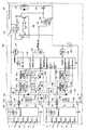
図6は、高電圧電動工具100の電気的な構成を変更した一例を示している。この変形例は、図5に示す回路構成に、二つのバイパス回路158を付加したものである。バイパス回路158は、それぞれの低電圧バッテリパック10に対して設けられている。バイパス回路158は、本体102内で、正極入力端子134aと負極入力端子134bを接続している。バイパス回路158には、ダイオード158aが設けられている。即ち、バイパス回路158は、低電圧バッテリパック10の正極出力端子24aと、負極出力端子24bを、ダイオード158aを介して互いに接続している。 FIG. 6 shows an example in which the electrical configuration of the high-voltage
ダイオード158aのアノードは負極入力端子134bに接続されており、ダイオード158aのカソードは正極入力端子134aに接続されている。従って、通常は、ダイオード158aに電流が流れることはなく、低電圧バッテリパック10の正極出力端子24aと負極出力端子24bは、電気的に切断された状態となっている。その一方で、低電圧バッテリパック10が過放電され、低電圧バッテリパック10の出力端子24a、24b間に逆電圧が発生すると、ダイオード158aに電流が流れる。即ち、バッテリパック10の出力端子24a、24b間が、バイパス回路158を通じて電気的に接続される。それにより、仮に一方の低電圧バッテリパック10のみが過放電されたとしても、その低電圧バッテリパック10が受けるダメージを抑制することができる。なお、バイパス回路158には、ヒューズ158bがさらに設けられており、バイパス回路158に大電流が流れた場合には、バイパス回路158が物理的に切断される。それにより、例えばダイオード158aがツェナー降伏を起こした場合でも、低電圧バッテリパック10の受けるダメージを抑制することができる。 The anode of the
図7は、高電圧電動工具100の電気的な構成を変更した他の一例を示している。この変形例は、図5に示す回路構成において、メインコントローラ152の電源を取り出す位置が変更されている。図7に示すように、メインスイッチ178が、低電圧バッテリパック10と電源回路142との間に介在すると、メインスイッチ178がオフされると同時に、メインコントローラ152がシャットダウンされる。それにより、高電圧電動工具100の非作動時において、メインコントローラ152が電力を無用に消費することを禁止することができる。 FIG. 7 shows another example in which the electrical configuration of the high-voltage
図8は、高電圧電動工具100の電気的な構成を変更した他の一例を示している。この変形例は、図7に示す上記の回路構成に、二つのバイパス回路158を付加したものである。バイパス回路158の構造、機能、及び効果は、先の図6に示す変形例の説明で述べた通りである。 FIG. 8 shows another example in which the electrical configuration of the high-voltage
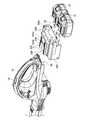
次に、図9、図10、図11を参照し、二種類のアダプタ200、300のうち、一方のアダプタ200について説明する。図9に示すように、アダプタ200は、複数の低電圧バッテリパック10を、高電圧電動工具70に接続するための装置である。アダプタ200は、高電圧電動工具70の本体72に着脱可能な本体側ユニット202と、複数の低電圧バッテリパック10が着脱可能なパック側ユニット206と、本体側ユニット202とパック側ユニット206を互いに接続している電気コード204を備えている。パック側ユニット206には、装着用フック206aが設けられており、ユーザの衣服やベルトに装着できるようになっている。 Next, with reference to FIGS. 9, 10, and 11, one
図10に示すように、本体側ユニット202は、概して、高電圧バッテリパック30に近似する外形形状を有している。本体側ユニット202には、高電圧バッテリパック30と同じように、コネクタ部220が設けられている。コネクタ部220は、高電圧電動工具70の本体72に設けられたパック取付部80に、スライド挿入することができる。コネクタ部220には、一対のレール222、正極出力端子224a、負極出力端子224b、オートストップ端子226が設けられている。本体側ユニット202をパック取付部80に取り付けると、本体側ユニット202の正極出力端子224aが、パック取付部80の正極入力端子84aに接続され、本体側ユニット202の負極出力端子224bが、パック取付部80の負極入力端子84bに接続される。それにより、本体側ユニット202は、高電圧電動工具70の本体72へ電気的に接続される。また、本体側ユニット202は、パック取付部80のロック受入穴88(図22参照)に係合し、本体側ユニット202をパック取付部80に固定するロック部材212を有している。このロック部材212による固定は、ロック解除ボタン214によって解除することができる。 As shown in FIG. 10, the
図11に示すように、パック側ユニット206には、二つのパック取付部230が設けられている。各々のパック取付部230は、一つの低電圧バッテリパック10が着脱可能であり、低電圧バッテリパック10をスライド可能に受け入れる。パック取付部230は、一対のレール232、正極入力端子234a、負極入力端子234b、ロック受入穴238を有している。このパック取付部230は、その構造において、先に説明した低電圧電動工具50のパック取付部60と実質的に等しい。二つのパック取付部230は、パック側ユニット206の下面に並んで配置されており、低電圧バッテリパック10が同一方向からそれぞれ挿入される。パック側ユニット206に取り付けられた二つの低電圧バッテリパック10は、コネクタ部220の正極出力端子224a及び負極出力端子224bに対して直列に接続される。それにより、二つの低電圧バッテリパック10は、略36ボルトの電圧によって、高電圧電動工具70の本体72へ電力を供給する。 As shown in FIG. 11, the
図11に示すように、パック側ユニット206には、二つの表示器260が設けられている。二つの表示器260は、二つのパック取付部230の上部にそれぞれ位置している。各々の表示器260は、一例ではあるが、発光ダイオードである。一方の表示器260は、一方のパック取付部230に取り付けられた低電圧バッテリパック10の充電レベルを表示し、他方の表示器260は、他方のパック取付部230に取り付けられた低電圧バッテリパック10の状態を表示する。各々の表示器260は、対応する低電圧バッテリパック10の充電レベルを表示することができ、特に、その充電レベルが再充電を必要とするレベルに達した時に、発光ダイオードを点灯させることができる。なお、表示器260は、対応する低電圧バッテリパック10の充電レベルを、少なくとも二段階に表示することも好ましい。あるいは、表示器160が、対応する低電圧バッテリパック10の充電レベルに代えて、あるいは、充電レベルに加えて、対応する低電圧バッテリパック10の温度異常を表示することも好ましい。 As shown in FIG. 11, the
二つの表示器260は、パック側ユニット206の一つの面に、並んで配置されており、その表示方向(即ち、発光ダイオードの発光方向)は同じ方向を向いている。従って、ユーザは、二つの表示器260を同時に視認し、二つの低電圧バッテリパック10の充電レベルを同時に把握することができる。また、それぞれの表示器260は、対応するパック取付部230の上方に配置されている。従って、例えば高電圧電動工具70が突然に停止した場合に、どちらの低電圧バッテリパック10に問題があるのかを、ユーザは直ちに判断することができる。なお、二つの表示器260は、パック側ユニット206に限られず、例えば本体側ユニット202に設けてもよい。二つの表示器260は、ユーザが同時に視認可能な他の位置へ配置することもできる。この場合、二つの表示器260が同一平面に配置されていると、ユーザは二つの表示器260を様々な方向から同時に視認することができる。 The two
ここで、表示器260は、各々の低電圧バッテリパック10に設けることもできる。先に説明したように、二つのパック取付部230は、並んで配置されているとともに、低電圧バッテリパック10を同一方向から受け入れる。従って、二つの低電圧バッテリパック10をパック側ユニット206に取り付けた時に、二つの表示器260は、同一平面内に並んで位置するとともに、その表示方向も同じ方向を向くことになる。ユーザは、二つの表示器260を様々な方向から同時に視認することができる。 Here, the
次に、図12を参照し、アダプタ200の電気的な構成について説明する。図12と図5を比較して明らかなように、アダプタ200の回路構成は、先に説明した高電圧電動工具100の本体102の回路構成の一部と実質的に同じである。詳しくは、アダプタ200の回路構成に、高電圧電動工具70の本体72の回路構成を併せたものが、図5に示す高電圧電動工具100の本体102の回路構成と実質的に等しくなる(ただし、パワーFET246を除く)。 Next, an electrical configuration of the
先ず、高電圧電動工具70の本体72の回路構成について説明する。高電圧電動工具70の本体72は、モータ76、メインスイッチ78、速度調節回路90、パワーFET94、ゲート制御トランジスタ92、及び分圧回路96を備えている。これらに係る構成については、高電圧電動工具100の本体102におけるモータ176、メインスイッチ178、速度調節回路190、パワーFET194、ゲート制御トランジスタ192、及び分圧回路196に係る構成と同じであるので、ここでは説明は省略する。だだし、モータ76には、アダプタ200を介して、二つの低電圧バッテリパック10が直列に接続されている。 First, the circuit configuration of the
アダプタ200は、メインコントローラ252、電源回路242、シャント抵抗250、電流検出回路248、放電保護信号入出力回路244、ヒューズ262を備えている。また、メインコントローラ252は、二つの表示器260へ電気的に接続されている。これらに係る構成については、高電圧電動工具100の本体102におけるメインコントローラ152、電源回路142、シャント抵抗150、電流検出回路148、放電保護信号入出力回路144、表示器160、ヒューズ162に係る構成と同じであるので、ここでは説明を省略する。 The
アダプタ200には、パワーFET246がさらに設けられている。パワーFET246は、低電圧バッテリパック10に接続される負極入力端子234bと、高電圧電動工具70に接続される負極出力端子224bとの間に設けられている。即ち、二つの低電圧バッテリパック10をモータ76に接続する回路であって、二つの低電圧バッテリパック10による放電電流が流れる回路上に位置している。メインコントローラ252は、パワーFET246のゲートに接続されており、パワーFET246を制御することができる。例えば、メインコントローラ252は、電流検出回路248からの出力電圧が所定値を超えた時に、パワーFET246をターンオフする。 The
ここで、パワーFET246の機能について説明を補足する。アダプタ200が高電圧電動工具70から取り外されると、アダプタ200のコネクタ部220は外部に露出する状態となる。このとき、アダプタ200に二つの低電圧バッテリパック10が取り付けられていると、コネクタ部220では、正極出力端子224aと負極出力端子224bの間に略36ボルトの電圧が発生する。正極出力端子224aと負極出力端子224bはスリット内に配設されているので、通常、両出力端子224a、224bに異物が接触することはない。しかしながら、両出力端子224a、224bに異物が接触する可能性を完全に否定することはできず、仮に、両出力端子224a、224bが異物によって短絡されたとすれば、低電圧バッテリパック10やアダプタ200の内部で過大な電流が流れてしまう。そこで、本実施形態では、アダプタ200の内部にパワーFET246が設けられおり、アダプタ200が高電圧電動工具70から取り外された状態でも、過大な電流が検出された時には、パワーFET246によって回路を遮断できるように構成されている。 Here, the description of the function of the
メインコントローラ252は、パック取付部230のオートストップ端子236に電気的に接続されており、バッテリコントローラ18からの信号電圧(例えば放電保護信号)を入力し、また、バッテリコントローラ18へ信号電圧(例えば放電保護解除信号)を出力することができる。メインコントローラ252からバッテリコントローラ18へ信号電圧を伝送する導電線路254、及び、バッテリコントローラ18からメインコントローラ252へ信号電圧を伝送する導電線路256には、カットオフスイッチ254a、256aがそれぞれ設けられている。また、高圧側に位置する低電圧バッテリパック10のバッテリコントローラ18については、導電線路254、256にレベルシフタ254b、256bがそれぞれ設けられている。これらの構成については、高電圧電動工具100の本体102におけるカットオフスイッチ254a、256a、レベルシフタ254b、256bに係る構成と同じであるので、ここでは説明を省略する。 The
以上のように、アダプタ200を用いることにより、ユーザは、高電圧電動工具70を、二つの低電圧バッテリパック10によって駆動することが可能となる。二つの低電圧バッテリパック10は、モータ76に対して直列に接続されることで、モータ76へ略36ボルトの電圧を印加する。それにより、定格電圧が36ボルトの高電圧電動工具70を、公称電圧が18ボルトの低電圧バッテリパック10によって駆動することが可能となる。ユーザは、公称電圧が36ボルトの高電圧バッテリパック30やその充電器を新たに購入することなく、既に保有する低電圧バッテリパック10を用いて、高電圧電動工具70を利用することが可能となる。低電圧バッテリパック10は、単独で低電圧電動工具50の電源としても使用できるので、ユーザは、既に保有する低電圧バッテリパック10やその充電器を、有効に活用することができる。 As described above, by using the
図13は、アダプタ200の電気的な構成を変更した一例を示している。この変形例は、図12に示す回路構成に、二つのバイパス回路258を付加したものである。バイパス回路258は、それぞれの低電圧バッテリパック10に対して設けられている。バイパス回路158には、ダイオード158aとヒューズ258bが設けられている。これらのバイパス回路258に係る構成については、図6及び図8に示す高電圧電動工具100の本体102におけるバイパス回路158に係る構成と同じであるので、ここでは説明を省略する。 FIG. 13 shows an example in which the electrical configuration of the
次に、図14、図15、図16を参照し、他方のアダプタ300について説明する。図14に示すように、アダプタ300もまた、複数の低電圧バッテリパック10を、高電圧電動工具70に接続するための装置である。このアダプタ300は、先に説明したアダプタ200とは異なり、一つのハウジングによって構成されている。このアダプタ300は、先に説明したアダプタ200の本体側ユニット202とパック側ユニット206を、一つのハウジングに一体化したものである。なお、このアダプタ300の電気的な構成は、上述したコード接続タイプのアダプタ200のものと同じであり、図12又は図13に示す通りである。 Next, the
図15に示すように、アダプタ300の上面には、コード接続タイプのアダプタ200の本体側ユニット202と同じく、コネクタ部220が設けられている。コネクタ部220は、高電圧電動工具70の本体72に設けられたパック取付部80に、スライド挿入することができる。コネクタ部220には、一対のレール222、正極出力端子224a、負極出力端子224b、オートストップ端子226が設けられている。二種類のアダプタ200、300の間で、コネクタ部220の構造は実質的に同一である。アダプタ300のコネクタ部220をパック取付部80に取り付けると、アダプタ300の正極出力端子224aは、パック取付部80の正極入力端子84aに接続され、アダプタ300の負極出力端子224bは、パック取付部80の負極入力端子84bに接続される。それにより、アダプタ300は、高電圧電動工具70の本体72へ電気的に接続される。 As shown in FIG. 15, a
図16に示すように、アダプタ300の下面には、コード接続タイプのアダプタ200のパック側ユニット206と同じく、二つのパック取付部230が設けられている。各々のパック取付部230は、一つの低電圧バッテリパック10が着脱可能であり、低電圧バッテリパック10をスライド可能に受け入れる。パック取付部230は、一対のレール232、正極入力端子234a、負極入力端子234b、ロック受入穴238を有している。二種類のアダプタ200、300の間で、パック取付部230の構造は実質的に同一である。二つのパック取付部230は、パック側ユニット206の下面に並んで配置されており、低電圧バッテリパック10が同一方向からそれぞれ挿入される。アダプタ300に取り付けられた二つの低電圧バッテリパック10は、コネクタ部220の正極出力端子224a及び負極出力端子224bに対して直列に接続される。それにより、二つの低電圧バッテリパック10は、略36ボルトの電圧によって、高電圧電動工具70の本体72へ電力を供給することができる。 As shown in FIG. 16, two
図15に示すように、アダプタ300にも、二つの表示器260が設けられている。二つの表示器260は、アダプタ300の後面300aに配置されている。二つの表示器260は、二つのパック取付部230の上部にそれぞれ位置している。各々の表示器260は、一例ではあるが、発光ダイオードである。一方の表示器260は、一方のパック取付部230に取り付けられた低電圧バッテリパック10の充電レベルを表示し、他方の表示器260は、他方のパック取付部230に取り付けられた低電圧バッテリパック10の状態を表示する。二つの表示器260は、アダプタ300の後面300aに、並んで配置されている。従って、ユーザは、二つの表示器260を同時に視認し、二つの低電圧バッテリパック10の充電レベルを同時に把握することができる。また、それぞれの表示器260は、対応するパック取付部230の上方に配置されている。従って、例えば高電圧電動工具70が突然に停止した場合に、どちらの低電圧バッテリパック10に問題があるのかを、ユーザは直ちに判断することができる。 As shown in FIG. 15, the
以上のように、アダプタ300を用いることによっても、ユーザは、高電圧電動工具70を、二つの低電圧バッテリパック10によって駆動することが可能となる。二つの低電圧バッテリパック10は、モータ76に対して直列に接続されることで、モータ76へ略36ボルトの電圧を印加する。それにより、定格電圧が36ボルトの高電圧電動工具70を、公称電圧が18ボルトの低電圧バッテリパック10によって駆動することが可能となる。ユーザは、公称電圧が36ボルトの高電圧バッテリパック30やその充電器を新たに購入することなく、既に保有する低電圧バッテリパック10を用いて、高電圧電動工具70を利用することが可能となる。低電圧バッテリパック10は、単独で低電圧電動工具50の電源としても使用できるので、ユーザは、既に保有する低電圧バッテリパック10やその充電器を、有効に活用することができる。 As described above, also by using the
以上、本発明の実施形態について詳細に説明したが、これらは例示に過ぎず、特許請求の範囲を限定するものではない。特許請求の範囲に記載の技術には、以上に例示した具体例を様々に変形、変更したものが含まれる。 As mentioned above, although embodiment of this invention was described in detail, these are only illustrations and do not limit a claim. The technology described in the claims includes various modifications and changes of the specific examples illustrated above.
本明細書では、低電圧電動工具50の一例として電動ドリルを説明し、高電圧電動工具70、100の一例として電動ブロワーを説明したが、本願明細書に開示された技術は、この種の電動工具に限られず、他の種類の電動工具にも広く適用することができる。 In the present specification, an electric drill has been described as an example of the low-voltage
本明細書または図面に説明した技術要素は、単独であるいは各種の組合せによって技術的有用性を発揮するものであり、出願時の請求項に記載の組合せに限定されるものではない。本明細書または図面に例示した技術は複数の目的を同時に達成するものであり、そのうちの一つの目的を達成すること自体で技術的有用性を持つものである。 The technical elements described in this specification or the drawings exhibit technical usefulness alone or in various combinations, and are not limited to the combinations described in the claims at the time of filing. The technology illustrated in this specification or the drawings achieves a plurality of objects at the same time, and achieving one of the objects itself has technical utility.
10:低電圧バッテリパック
18:バッテリコントローラ
100:高電圧電動工具
102:高電圧電動工具の本体
130:高電圧電動工具のパック取付部
152:高電圧電動工具のメインコントローラ
154a、156a、254a、256a:カットオフスイッチ
154b、156b、254b、256b:レベルシフタ
158:バイパス回路
158a:バイパス回路のダイオード
158b:バイパス回路のヒューズ
160:表示器
176:モータ
200、300:アダプタ
202:アダプタの本体側ユニット
204:アダプタの電気コード
206:アダプタのパック側ユニット
220:アダプタのコネクタ部
230:アダプタのパック取付部
252:アダプタのメインコントローラ10: Low voltage battery pack 18: Battery controller 100: High voltage electric tool 102: High voltage electric tool main body 130: High voltage electric tool pack mounting portion 152: High voltage electric tool
Claims (16)
Translated fromJapanese各々のバッテリパックの集積回路から出力される信号電圧がそれぞれ入力される制御回路と、
少なくとも一つのバッテリパックの集積回路と電動工具の制御回路の間に設けられ、バッテリパックの集積回路が出力する信号電圧のレベルを、電動工具の制御回路が許容するレベルに変圧するレベルシフタと、
を備える電動工具。A power tool for connecting a plurality of battery packs in series to be a power source, each battery pack having an integrated circuit that outputs a signal voltage,
A control circuit to which a signal voltage output from an integrated circuit of each battery pack is input;
A level shifter provided between the integrated circuit of the at least one battery pack and the control circuit of the power tool, and transforming the level of the signal voltage output from the integrated circuit of the battery pack to a level allowed by the control circuit of the power tool;
A power tool comprising:
電動工具の制御回路が出力する信号電圧が、第2のレベルシフタによって変圧された後に、その少なくとも一つのバッテリパックの集積回路に入力されることを特徴とする請求項1から3のいずれか一項に記載の電動工具。A second level shifter provided between the integrated circuit of the at least one battery pack and the control circuit of the power tool, and transforms the level of the signal voltage output from the control circuit of the power tool to a level allowed by the integrated circuit of the battery pack. Further comprising
The signal voltage output from the control circuit of the power tool is transformed into the integrated circuit of at least one battery pack after being transformed by the second level shifter. The electric tool as described in.
バッテリパックの正極出力端子と負極出力端子をダイオードを介して接続するバイパス回路を備えることを特徴とする電動工具。An electric tool that uses a plurality of battery packs connected in series as a power source,
An electric tool comprising a bypass circuit for connecting a positive electrode output terminal and a negative electrode output terminal of a battery pack via a diode.
各々のバッテリパックの集積回路から出力される信号電圧がそれぞれ入力される制御回路と、
少なくとも一つのバッテリパックの集積回路とアダプタの制御回路の間に設けられ、バッテリパックの集積回路が出力する信号電圧のレベルを、アダプタの制御回路が許容するレベルに変圧するレベルシフタと、
を備えるアダプタ。An adapter that connects a plurality of battery packs in series to the main body of the electric tool, each battery pack having an integrated circuit that outputs a signal voltage,
A control circuit to which a signal voltage output from an integrated circuit of each battery pack is input;
A level shifter provided between the integrated circuit of the at least one battery pack and the control circuit of the adapter, and transforming the level of the signal voltage output from the integrated circuit of the battery pack to a level allowed by the control circuit of the adapter;
With adapter.
アダプタの制御回路が出力する信号電圧が、第2のレベルシフタによって変圧された後に、その少なくとも一つのバッテリパックの集積回路に入力されることを特徴とする請求項9に記載のアダプタ。A second level shifter provided between the integrated circuit of the at least one battery pack and the control circuit of the adapter, and transforms the level of the signal voltage output from the integrated circuit of the power tool to a level allowed by the control circuit of the battery pack. In addition,
The adapter according to claim 9, wherein the signal voltage output from the control circuit of the adapter is input to the integrated circuit of the at least one battery pack after being transformed by the second level shifter.
バッテリパックの正極出力端子と負極出力端子をダイオードを介して接続するバイパス回路を備えることを特徴とするアダプタ。An adapter for connecting a plurality of battery packs in series to the body of the electric tool,
An adapter comprising a bypass circuit that connects a positive electrode output terminal and a negative electrode output terminal of a battery pack via a diode.
Priority Applications (6)
| Application Number | Priority Date | Filing Date | Title |
|---|---|---|---|
| JP2010029506AJP5432761B2 (en) | 2010-02-12 | 2010-02-12 | Electric tool powered by multiple battery packs |
| US12/888,101US8813866B2 (en) | 2010-02-12 | 2010-09-22 | Electric tool powered by a plurality of battery packs and adapter therefor |
| EP11703492.6AEP2534744B1 (en) | 2010-02-12 | 2011-01-17 | Power supply interface for electric tool powered by a plurality of battery packs |
| RU2012138953/07ARU2505904C1 (en) | 2010-02-12 | 2011-01-17 | Power supply interface for electric tool powered by plurality of battery packs |
| PCT/JP2011/051146WO2011099348A1 (en) | 2010-02-12 | 2011-01-17 | Power supply interface for electric tool powered by a plurality of battery packs |
| CN201180009359XACN102763304A (en) | 2010-02-12 | 2011-01-17 | Power supply interface for electric tool powered by a plurality of battery packs |
Applications Claiming Priority (1)
| Application Number | Priority Date | Filing Date | Title |
|---|---|---|---|
| JP2010029506AJP5432761B2 (en) | 2010-02-12 | 2010-02-12 | Electric tool powered by multiple battery packs |
Publications (2)
| Publication Number | Publication Date |
|---|---|
| JP2011161603Atrue JP2011161603A (en) | 2011-08-25 |
| JP5432761B2 JP5432761B2 (en) | 2014-03-05 |
Family
ID=44368840
Family Applications (1)
| Application Number | Title | Priority Date | Filing Date |
|---|---|---|---|
| JP2010029506AActiveJP5432761B2 (en) | 2010-02-12 | 2010-02-12 | Electric tool powered by multiple battery packs |
Country Status (6)
| Country | Link |
|---|---|
| US (1) | US8813866B2 (en) |
| EP (1) | EP2534744B1 (en) |
| JP (1) | JP5432761B2 (en) |
| CN (1) | CN102763304A (en) |
| RU (1) | RU2505904C1 (en) |
| WO (1) | WO2011099348A1 (en) |
Cited By (48)
| Publication number | Priority date | Publication date | Assignee | Title |
|---|---|---|---|---|
| WO2012017833A1 (en)* | 2010-08-04 | 2012-02-09 | パナソニック電工パワーツール株式会社 | Electric tool adaptor and electric tool system using same |
| JP2013042672A (en)* | 2011-08-22 | 2013-03-04 | Makita Corp | Rechargeable cultivator |
| JP2013109894A (en)* | 2011-11-18 | 2013-06-06 | Makita Corp | Battery adapter |
| JP2014017954A (en)* | 2012-07-07 | 2014-01-30 | Hitachi Koki Co Ltd | Power supply device |
| WO2014119174A1 (en)* | 2013-02-01 | 2014-08-07 | 株式会社マキタ | Electric shearing device for gardening |
| WO2014119093A1 (en)* | 2013-02-01 | 2014-08-07 | 株式会社マキタ | Electric reciprocating cutting tool |
| WO2014119210A1 (en)* | 2013-02-01 | 2014-08-07 | 株式会社マキタ | Electric-powered tool |
| WO2014119131A1 (en)* | 2013-02-01 | 2014-08-07 | 株式会社マキタ | Rechargeable cutting tool |
| WO2014119135A1 (en)* | 2013-02-01 | 2014-08-07 | 株式会社マキタ | Electric power tool |
| WO2014119211A1 (en)* | 2013-02-01 | 2014-08-07 | 株式会社マキタ | Cutting tool |
| WO2014119188A1 (en)* | 2013-02-01 | 2014-08-07 | 株式会社マキタ | Electric power tool |
| WO2014119128A1 (en)* | 2013-02-01 | 2014-08-07 | 株式会社マキタ | Handheld electric cutting machine |
| WO2014119116A1 (en)* | 2013-02-01 | 2014-08-07 | 株式会社マキタ | Electric brush cutter |
| WO2014119757A1 (en)* | 2013-02-01 | 2014-08-07 | 株式会社マキタ | Power tool |
| WO2014119132A1 (en)* | 2013-02-01 | 2014-08-07 | 株式会社マキタ | Desktop cutting machine |
| WO2014119130A1 (en)* | 2013-02-01 | 2014-08-07 | 株式会社マキタ | Sprayer |
| WO2014119758A1 (en)* | 2013-02-01 | 2014-08-07 | 株式会社マキタ | Power tool |
| WO2014119759A1 (en)* | 2013-02-01 | 2014-08-07 | 株式会社マキタ | Hammering tool |
| WO2014119127A1 (en)* | 2013-02-01 | 2014-08-07 | 株式会社マキタ | Handheld electric grinding machine |
| WO2014119126A1 (en)* | 2013-02-01 | 2014-08-07 | 株式会社マキタ | Handheld electric cutting machine |
| WO2014119756A1 (en)* | 2013-02-01 | 2014-08-07 | 株式会社マキタ | Power tool |
| WO2014119181A1 (en)* | 2013-02-01 | 2014-08-07 | 株式会社マキタ | Blower |
| JP2014148008A (en)* | 2013-02-01 | 2014-08-21 | Makita Corp | Electric appliance and body of the same |
| WO2014142112A1 (en)* | 2013-03-12 | 2014-09-18 | 株式会社マキタ | Impact tool |
| WO2014168114A1 (en)* | 2013-04-09 | 2014-10-16 | 株式会社マキタ | Power tool |
| JP2015074060A (en)* | 2013-10-10 | 2015-04-20 | 株式会社マキタ | Electric power tool |
| JP2015199169A (en)* | 2014-04-08 | 2015-11-12 | 株式会社マキタ | Electric tool and its sales system |
| JP2016185595A (en)* | 2016-08-03 | 2016-10-27 | 株式会社マキタ | Hand-held electric cutter |
| JPWO2015145583A1 (en)* | 2014-03-25 | 2017-04-13 | 株式会社マキタ | Impact tool |
| US9630310B2 (en) | 2013-02-01 | 2017-04-25 | Makita Corporation | Electric tool |
| JP2017113878A (en)* | 2017-02-21 | 2017-06-29 | 株式会社マキタ | Tabletop cutting machine |
| JP2017526539A (en)* | 2014-06-10 | 2017-09-14 | ローベルト ボッシュ ゲゼルシャフト ミット ベシュレンクテル ハフツング | A system comprising at least an electronically commutated electric motor having a defined design size and at least one voltage class rechargeable battery |
| JP2018001407A (en)* | 2017-10-11 | 2018-01-11 | 株式会社マキタ | Hand-held electric cutter |
| JP2018062057A (en)* | 2017-11-30 | 2018-04-19 | 株式会社マキタ | Table cutter |
| JP2018075703A (en)* | 2016-11-02 | 2018-05-17 | 株式会社マキタ | Electric tool |
| US10076833B2 (en) | 2013-10-10 | 2018-09-18 | Makita Corporation | Electric tools |
| JP2018161740A (en)* | 2018-07-27 | 2018-10-18 | 株式会社マキタ | Electric tool |
| WO2019065088A1 (en)* | 2017-09-29 | 2019-04-04 | 工機ホールディングス株式会社 | Electric device |
| JP2019193498A (en)* | 2018-04-27 | 2019-10-31 | 工機ホールディングス株式会社 | Electrical machine |
| WO2020044939A1 (en)* | 2018-08-28 | 2020-03-05 | 株式会社マキタ | High-pressure cleaner |
| JP2020069694A (en)* | 2018-10-30 | 2020-05-07 | 株式会社マキタ | Cutting machine |
| JP2020532442A (en)* | 2018-05-07 | 2020-11-12 | ▲蘇▼州宝▲時▼得▲電▼▲動▼工具有限公司 | Battery pack and power tool unit |
| WO2021070377A1 (en)* | 2019-10-11 | 2021-04-15 | 本田技研工業株式会社 | Power reception device, battery unit, electric power unit and work machine |
| US11148272B2 (en) | 2013-02-01 | 2021-10-19 | Makita Corporation | Power tool |
| JP2022507198A (en)* | 2018-11-13 | 2022-01-18 | 深▲せん▼市華思旭科技有限公司 | Power tool for power tools with vehicle starting function |
| JPWO2022172776A1 (en)* | 2021-02-12 | 2022-08-18 | ||
| JP2022131975A (en)* | 2021-02-26 | 2022-09-07 | 工機ホールディングス株式会社 | electrical equipment |
| US11837901B2 (en) | 2018-11-13 | 2023-12-05 | Shenzhen Carku Technology Co., Limited | Electric tool power supply having vehicle starting function |
Families Citing this family (549)
| Publication number | Priority date | Publication date | Assignee | Title |
|---|---|---|---|---|
| US20070084897A1 (en) | 2003-05-20 | 2007-04-19 | Shelton Frederick E Iv | Articulating surgical stapling instrument incorporating a two-piece e-beam firing mechanism |
| US9060770B2 (en) | 2003-05-20 | 2015-06-23 | Ethicon Endo-Surgery, Inc. | Robotically-driven surgical instrument with E-beam driver |
| US11890012B2 (en) | 2004-07-28 | 2024-02-06 | Cilag Gmbh International | Staple cartridge comprising cartridge body and attached support |
| US8215531B2 (en) | 2004-07-28 | 2012-07-10 | Ethicon Endo-Surgery, Inc. | Surgical stapling instrument having a medical substance dispenser |
| US11998198B2 (en) | 2004-07-28 | 2024-06-04 | Cilag Gmbh International | Surgical stapling instrument incorporating a two-piece E-beam firing mechanism |
| US9072535B2 (en) | 2011-05-27 | 2015-07-07 | Ethicon Endo-Surgery, Inc. | Surgical stapling instruments with rotatable staple deployment arrangements |
| US7934630B2 (en) | 2005-08-31 | 2011-05-03 | Ethicon Endo-Surgery, Inc. | Staple cartridges for forming staples having differing formed staple heights |
| US9237891B2 (en) | 2005-08-31 | 2016-01-19 | Ethicon Endo-Surgery, Inc. | Robotically-controlled surgical stapling devices that produce formed staples having different lengths |
| US11484312B2 (en) | 2005-08-31 | 2022-11-01 | Cilag Gmbh International | Staple cartridge comprising a staple driver arrangement |
| US7673781B2 (en) | 2005-08-31 | 2010-03-09 | Ethicon Endo-Surgery, Inc. | Surgical stapling device with staple driver that supports multiple wire diameter staples |
| US10159482B2 (en) | 2005-08-31 | 2018-12-25 | Ethicon Llc | Fastener cartridge assembly comprising a fixed anvil and different staple heights |
| US11246590B2 (en) | 2005-08-31 | 2022-02-15 | Cilag Gmbh International | Staple cartridge including staple drivers having different unfired heights |
| US7669746B2 (en) | 2005-08-31 | 2010-03-02 | Ethicon Endo-Surgery, Inc. | Staple cartridges for forming staples having differing formed staple heights |
| US20070106317A1 (en) | 2005-11-09 | 2007-05-10 | Shelton Frederick E Iv | Hydraulically and electrically actuated articulation joints for surgical instruments |
| US7753904B2 (en) | 2006-01-31 | 2010-07-13 | Ethicon Endo-Surgery, Inc. | Endoscopic surgical instrument with a handle that can articulate with respect to the shaft |
| US11278279B2 (en) | 2006-01-31 | 2022-03-22 | Cilag Gmbh International | Surgical instrument assembly |
| US8708213B2 (en) | 2006-01-31 | 2014-04-29 | Ethicon Endo-Surgery, Inc. | Surgical instrument having a feedback system |
| US20110024477A1 (en) | 2009-02-06 | 2011-02-03 | Hall Steven G | Driven Surgical Stapler Improvements |
| US7845537B2 (en) | 2006-01-31 | 2010-12-07 | Ethicon Endo-Surgery, Inc. | Surgical instrument having recording capabilities |
| US11793518B2 (en) | 2006-01-31 | 2023-10-24 | Cilag Gmbh International | Powered surgical instruments with firing system lockout arrangements |
| US8186555B2 (en) | 2006-01-31 | 2012-05-29 | Ethicon Endo-Surgery, Inc. | Motor-driven surgical cutting and fastening instrument with mechanical closure system |
| US11224427B2 (en) | 2006-01-31 | 2022-01-18 | Cilag Gmbh International | Surgical stapling system including a console and retraction assembly |
| US20120292367A1 (en) | 2006-01-31 | 2012-11-22 | Ethicon Endo-Surgery, Inc. | Robotically-controlled end effector |
| US8820603B2 (en) | 2006-01-31 | 2014-09-02 | Ethicon Endo-Surgery, Inc. | Accessing data stored in a memory of a surgical instrument |
| US20110295295A1 (en) | 2006-01-31 | 2011-12-01 | Ethicon Endo-Surgery, Inc. | Robotically-controlled surgical instrument having recording capabilities |
| US8236010B2 (en) | 2006-03-23 | 2012-08-07 | Ethicon Endo-Surgery, Inc. | Surgical fastener and cutter with mimicking end effector |
| US8992422B2 (en) | 2006-03-23 | 2015-03-31 | Ethicon Endo-Surgery, Inc. | Robotically-controlled endoscopic accessory channel |
| US8322455B2 (en) | 2006-06-27 | 2012-12-04 | Ethicon Endo-Surgery, Inc. | Manually driven surgical cutting and fastening instrument |
| US10568652B2 (en) | 2006-09-29 | 2020-02-25 | Ethicon Llc | Surgical staples having attached drivers of different heights and stapling instruments for deploying the same |
| US7506791B2 (en) | 2006-09-29 | 2009-03-24 | Ethicon Endo-Surgery, Inc. | Surgical stapling instrument with mechanical mechanism for limiting maximum tissue compression |
| US11980366B2 (en) | 2006-10-03 | 2024-05-14 | Cilag Gmbh International | Surgical instrument |
| US11291441B2 (en) | 2007-01-10 | 2022-04-05 | Cilag Gmbh International | Surgical instrument with wireless communication between control unit and remote sensor |
| US8652120B2 (en) | 2007-01-10 | 2014-02-18 | Ethicon Endo-Surgery, Inc. | Surgical instrument with wireless communication between control unit and sensor transponders |
| US8684253B2 (en) | 2007-01-10 | 2014-04-01 | Ethicon Endo-Surgery, Inc. | Surgical instrument with wireless communication between a control unit of a robotic system and remote sensor |
| US8632535B2 (en) | 2007-01-10 | 2014-01-21 | Ethicon Endo-Surgery, Inc. | Interlock and surgical instrument including same |
| US20080169333A1 (en) | 2007-01-11 | 2008-07-17 | Shelton Frederick E | Surgical stapler end effector with tapered distal end |
| US11039836B2 (en) | 2007-01-11 | 2021-06-22 | Cilag Gmbh International | Staple cartridge for use with a surgical stapling instrument |
| US7673782B2 (en) | 2007-03-15 | 2010-03-09 | Ethicon Endo-Surgery, Inc. | Surgical stapling instrument having a releasable buttress material |
| US8893946B2 (en) | 2007-03-28 | 2014-11-25 | Ethicon Endo-Surgery, Inc. | Laparoscopic tissue thickness and clamp load measuring devices |
| US8931682B2 (en) | 2007-06-04 | 2015-01-13 | Ethicon Endo-Surgery, Inc. | Robotically-controlled shaft based rotary drive systems for surgical instruments |
| US11564682B2 (en) | 2007-06-04 | 2023-01-31 | Cilag Gmbh International | Surgical stapler device |
| US7753245B2 (en) | 2007-06-22 | 2010-07-13 | Ethicon Endo-Surgery, Inc. | Surgical stapling instruments |
| US11849941B2 (en) | 2007-06-29 | 2023-12-26 | Cilag Gmbh International | Staple cartridge having staple cavities extending at a transverse angle relative to a longitudinal cartridge axis |
| US8636736B2 (en) | 2008-02-14 | 2014-01-28 | Ethicon Endo-Surgery, Inc. | Motorized surgical cutting and fastening instrument |
| JP5410110B2 (en) | 2008-02-14 | 2014-02-05 | エシコン・エンド−サージェリィ・インコーポレイテッド | Surgical cutting / fixing instrument with RF electrode |
| US7819298B2 (en) | 2008-02-14 | 2010-10-26 | Ethicon Endo-Surgery, Inc. | Surgical stapling apparatus with control features operable with one hand |
| US8573465B2 (en) | 2008-02-14 | 2013-11-05 | Ethicon Endo-Surgery, Inc. | Robotically-controlled surgical end effector system with rotary actuated closure systems |
| US8758391B2 (en) | 2008-02-14 | 2014-06-24 | Ethicon Endo-Surgery, Inc. | Interchangeable tools for surgical instruments |
| US11986183B2 (en) | 2008-02-14 | 2024-05-21 | Cilag Gmbh International | Surgical cutting and fastening instrument comprising a plurality of sensors to measure an electrical parameter |
| US9179912B2 (en) | 2008-02-14 | 2015-11-10 | Ethicon Endo-Surgery, Inc. | Robotically-controlled motorized surgical cutting and fastening instrument |
| US7866527B2 (en) | 2008-02-14 | 2011-01-11 | Ethicon Endo-Surgery, Inc. | Surgical stapling apparatus with interlockable firing system |
| US11272927B2 (en) | 2008-02-15 | 2022-03-15 | Cilag Gmbh International | Layer arrangements for surgical staple cartridges |
| US9585657B2 (en) | 2008-02-15 | 2017-03-07 | Ethicon Endo-Surgery, Llc | Actuator for releasing a layer of material from a surgical end effector |
| EP2110921B1 (en) | 2008-04-14 | 2013-06-19 | Stanley Black & Decker, Inc. | Battery management system for a cordless tool |
| US9776296B2 (en) | 2008-05-09 | 2017-10-03 | Milwaukee Electric Tool Corporation | Power tool dust collector |
| US8210411B2 (en) | 2008-09-23 | 2012-07-03 | Ethicon Endo-Surgery, Inc. | Motor-driven surgical cutting instrument |
| US11648005B2 (en) | 2008-09-23 | 2023-05-16 | Cilag Gmbh International | Robotically-controlled motorized surgical instrument with an end effector |
| US9005230B2 (en) | 2008-09-23 | 2015-04-14 | Ethicon Endo-Surgery, Inc. | Motorized surgical instrument |
| US9386983B2 (en) | 2008-09-23 | 2016-07-12 | Ethicon Endo-Surgery, Llc | Robotically-controlled motorized surgical instrument |
| US8608045B2 (en) | 2008-10-10 | 2013-12-17 | Ethicon Endo-Sugery, Inc. | Powered surgical cutting and stapling apparatus with manually retractable firing system |
| US8517239B2 (en) | 2009-02-05 | 2013-08-27 | Ethicon Endo-Surgery, Inc. | Surgical stapling instrument comprising a magnetic element driver |
| RU2525225C2 (en) | 2009-02-06 | 2014-08-10 | Этикон Эндо-Серджери, Инк. | Improvement of drive surgical suturing instrument |
| US8444036B2 (en) | 2009-02-06 | 2013-05-21 | Ethicon Endo-Surgery, Inc. | Motor driven surgical fastener device with mechanisms for adjusting a tissue gap within the end effector |
| US8220688B2 (en) | 2009-12-24 | 2012-07-17 | Ethicon Endo-Surgery, Inc. | Motor-driven surgical cutting instrument with electric actuator directional control assembly |
| US8851354B2 (en) | 2009-12-24 | 2014-10-07 | Ethicon Endo-Surgery, Inc. | Surgical cutting instrument that analyzes tissue thickness |
| JP5461221B2 (en) | 2010-02-12 | 2014-04-02 | 株式会社マキタ | Electric tool powered by multiple battery packs |
| JP5616104B2 (en)* | 2010-04-12 | 2014-10-29 | 株式会社マキタ | Power tools powered by battery packs and their adapters |
| US8783543B2 (en) | 2010-07-30 | 2014-07-22 | Ethicon Endo-Surgery, Inc. | Tissue acquisition arrangements and methods for surgical stapling devices |
| JP2012048885A (en)* | 2010-08-25 | 2012-03-08 | Makita Corp | Battery device |
| JP2012049074A (en) | 2010-08-30 | 2012-03-08 | Makita Corp | Battery pack of electric tool |
| JP2012054007A (en)* | 2010-08-31 | 2012-03-15 | Makita Corp | Battery device for power tool |
| US9016542B2 (en) | 2010-09-30 | 2015-04-28 | Ethicon Endo-Surgery, Inc. | Staple cartridge comprising compressible distortion resistant components |
| US9301753B2 (en) | 2010-09-30 | 2016-04-05 | Ethicon Endo-Surgery, Llc | Expandable tissue thickness compensator |
| US11925354B2 (en) | 2010-09-30 | 2024-03-12 | Cilag Gmbh International | Staple cartridge comprising staples positioned within a compressible portion thereof |
| US9351730B2 (en) | 2011-04-29 | 2016-05-31 | Ethicon Endo-Surgery, Llc | Tissue thickness compensator comprising channels |
| US10945731B2 (en) | 2010-09-30 | 2021-03-16 | Ethicon Llc | Tissue thickness compensator comprising controlled release and expansion |
| US9629814B2 (en) | 2010-09-30 | 2017-04-25 | Ethicon Endo-Surgery, Llc | Tissue thickness compensator configured to redistribute compressive forces |
| US11812965B2 (en) | 2010-09-30 | 2023-11-14 | Cilag Gmbh International | Layer of material for a surgical end effector |
| US9232941B2 (en) | 2010-09-30 | 2016-01-12 | Ethicon Endo-Surgery, Inc. | Tissue thickness compensator comprising a reservoir |
| US11298125B2 (en) | 2010-09-30 | 2022-04-12 | Cilag Gmbh International | Tissue stapler having a thickness compensator |
| US12213666B2 (en) | 2010-09-30 | 2025-02-04 | Cilag Gmbh International | Tissue thickness compensator comprising layers |
| US9364233B2 (en) | 2010-09-30 | 2016-06-14 | Ethicon Endo-Surgery, Llc | Tissue thickness compensators for circular surgical staplers |
| US9277919B2 (en) | 2010-09-30 | 2016-03-08 | Ethicon Endo-Surgery, Llc | Tissue thickness compensator comprising fibers to produce a resilient load |
| RU2013119928A (en) | 2010-09-30 | 2014-11-10 | Этикон Эндо-Серджери, Инк. | A STAPLING SYSTEM CONTAINING A RETAINING MATRIX AND A LEVELING MATRIX |
| US9055941B2 (en) | 2011-09-23 | 2015-06-16 | Ethicon Endo-Surgery, Inc. | Staple cartridge including collapsible deck |
| US9386988B2 (en) | 2010-09-30 | 2016-07-12 | Ethicon End-Surgery, LLC | Retainer assembly including a tissue thickness compensator |
| US9788834B2 (en) | 2010-09-30 | 2017-10-17 | Ethicon Llc | Layer comprising deployable attachment members |
| US9220501B2 (en) | 2010-09-30 | 2015-12-29 | Ethicon Endo-Surgery, Inc. | Tissue thickness compensators |
| US8695866B2 (en) | 2010-10-01 | 2014-04-15 | Ethicon Endo-Surgery, Inc. | Surgical instrument having a power control circuit |
| AU2012250197B2 (en) | 2011-04-29 | 2017-08-10 | Ethicon Endo-Surgery, Inc. | Staple cartridge comprising staples positioned within a compressible portion thereof |
| US11207064B2 (en) | 2011-05-27 | 2021-12-28 | Cilag Gmbh International | Automated end effector component reloading system for use with a robotic system |
| DE102011113126B4 (en)* | 2011-09-14 | 2015-05-13 | Olaf Storz | Power unit and medical hand-held device |
| US9050084B2 (en) | 2011-09-23 | 2015-06-09 | Ethicon Endo-Surgery, Inc. | Staple cartridge including collapsible deck arrangement |
| US9044230B2 (en) | 2012-02-13 | 2015-06-02 | Ethicon Endo-Surgery, Inc. | Surgical cutting and fastening instrument with apparatus for determining cartridge and firing motion status |
| WO2013139372A1 (en) | 2012-03-19 | 2013-09-26 | Husqvarna Ab | Power adapter for cordless power tools |
| EP2828907B1 (en) | 2012-03-19 | 2017-07-19 | Husqvarna AB | Carrier system for a backpack energy source, energy source and backpack energy source assembly |
| DE102012204538A1 (en)* | 2012-03-21 | 2013-09-26 | Robert Bosch Gmbh | Storage for electrical energy and recording device for at least one memory for an electrically driven vehicle |
| US10084331B2 (en)* | 2012-03-25 | 2018-09-25 | Gbatteries Energy Canada Inc. | Systems and methods for enhancing the performance and utilization of battery systems |
| BR112014024098B1 (en) | 2012-03-28 | 2021-05-25 | Ethicon Endo-Surgery, Inc. | staple cartridge |
| MX358135B (en) | 2012-03-28 | 2018-08-06 | Ethicon Endo Surgery Inc | Tissue thickness compensator comprising a plurality of layers. |
| JP6224070B2 (en) | 2012-03-28 | 2017-11-01 | エシコン・エンド−サージェリィ・インコーポレイテッドEthicon Endo−Surgery,Inc. | Retainer assembly including tissue thickness compensator |
| DE102012104538A1 (en) | 2012-05-25 | 2013-11-28 | Gustav Klauke Gmbh | Tool |
| US9101358B2 (en) | 2012-06-15 | 2015-08-11 | Ethicon Endo-Surgery, Inc. | Articulatable surgical instrument comprising a firing drive |
| US11278284B2 (en) | 2012-06-28 | 2022-03-22 | Cilag Gmbh International | Rotary drive arrangements for surgical instruments |
| US20140005718A1 (en) | 2012-06-28 | 2014-01-02 | Ethicon Endo-Surgery, Inc. | Multi-functional powered surgical device with external dissection features |
| US9289256B2 (en) | 2012-06-28 | 2016-03-22 | Ethicon Endo-Surgery, Llc | Surgical end effectors having angled tissue-contacting surfaces |
| US12383267B2 (en) | 2012-06-28 | 2025-08-12 | Cilag Gmbh International | Robotically powered surgical device with manually-actuatable reversing system |
| BR112014032776B1 (en) | 2012-06-28 | 2021-09-08 | Ethicon Endo-Surgery, Inc | SURGICAL INSTRUMENT SYSTEM AND SURGICAL KIT FOR USE WITH A SURGICAL INSTRUMENT SYSTEM |
| US20140001231A1 (en) | 2012-06-28 | 2014-01-02 | Ethicon Endo-Surgery, Inc. | Firing system lockout arrangements for surgical instruments |
| JP6290201B2 (en) | 2012-06-28 | 2018-03-07 | エシコン・エンド−サージェリィ・インコーポレイテッドEthicon Endo−Surgery,Inc. | Lockout for empty clip cartridge |
| US9282974B2 (en) | 2012-06-28 | 2016-03-15 | Ethicon Endo-Surgery, Llc | Empty clip cartridge lockout |
| US9408606B2 (en) | 2012-06-28 | 2016-08-09 | Ethicon Endo-Surgery, Llc | Robotically powered surgical device with manually-actuatable reversing system |
| JP5962983B2 (en)* | 2012-08-30 | 2016-08-03 | 日立工機株式会社 | Electric tool |
| US9018914B2 (en)* | 2012-10-26 | 2015-04-28 | Maxim Integrated Products, Inc. | Low side NMOS protection circuit for battery pack application |
| JP6315541B2 (en)* | 2013-02-01 | 2018-04-25 | 株式会社マキタ | Brush cutter |
| JP2014148117A (en) | 2013-02-01 | 2014-08-21 | Makita Corp | Chain saw |
| US20150328796A1 (en)* | 2013-02-01 | 2015-11-19 | Makita Corporation | Cutting device |
| US10000900B2 (en)* | 2013-02-20 | 2018-06-19 | Chervon (Hk) Limited | Handheld blower having engine cooling flow |
| US9603497B2 (en) | 2013-02-20 | 2017-03-28 | Chevron (Hk) Limited | Handheld blower |
| US10337526B2 (en) | 2015-05-11 | 2019-07-02 | Chervon (Hk) Limited | Blower |
| US11248626B2 (en) | 2013-02-20 | 2022-02-15 | Chervon (Hk) Limited | Handheld blower |
| US9468438B2 (en) | 2013-03-01 | 2016-10-18 | Eticon Endo-Surgery, LLC | Sensor straightened end effector during removal through trocar |
| BR112015021082B1 (en) | 2013-03-01 | 2022-05-10 | Ethicon Endo-Surgery, Inc | surgical instrument |
| RU2672520C2 (en) | 2013-03-01 | 2018-11-15 | Этикон Эндо-Серджери, Инк. | Hingedly turnable surgical instruments with conducting ways for signal transfer |
| US9629629B2 (en) | 2013-03-14 | 2017-04-25 | Ethicon Endo-Surgey, LLC | Control systems for surgical instruments |
| US9808244B2 (en) | 2013-03-14 | 2017-11-07 | Ethicon Llc | Sensor arrangements for absolute positioning system for surgical instruments |
| US9572577B2 (en) | 2013-03-27 | 2017-02-21 | Ethicon Endo-Surgery, Llc | Fastener cartridge comprising a tissue thickness compensator including openings therein |
| US9795384B2 (en) | 2013-03-27 | 2017-10-24 | Ethicon Llc | Fastener cartridge comprising a tissue thickness compensator and a gap setting element |
| BR112015026109B1 (en) | 2013-04-16 | 2022-02-22 | Ethicon Endo-Surgery, Inc | surgical instrument |
| US9826976B2 (en) | 2013-04-16 | 2017-11-28 | Ethicon Llc | Motor driven surgical instruments with lockable dual drive shafts |
| US9574644B2 (en) | 2013-05-30 | 2017-02-21 | Ethicon Endo-Surgery, Llc | Power module for use with a surgical instrument |
| DE202013102567U1 (en)* | 2013-06-14 | 2013-07-17 | Einhell Germany Ag | Mobile electrical device with at least two lithium-ion batteries and arrangement of two such electrically connected in series accumulators |
| JP5746276B2 (en)* | 2013-07-17 | 2015-07-08 | ファナック株式会社 | Motor controller for protecting machine tools during power outages |
| MX369362B (en) | 2013-08-23 | 2019-11-06 | Ethicon Endo Surgery Llc | Firing member retraction devices for powered surgical instruments. |
| US9775609B2 (en)* | 2013-08-23 | 2017-10-03 | Ethicon Llc | Tamper proof circuit for surgical instrument battery pack |
| USD741557S1 (en) | 2014-01-15 | 2015-10-20 | Milwaukee Electric Tool Corporation | Dust collector |
| USD742081S1 (en) | 2014-01-15 | 2015-10-27 | Milwaukee Electric Tool Corporation | Dust collector |
| US9962161B2 (en) | 2014-02-12 | 2018-05-08 | Ethicon Llc | Deliverable surgical instrument |
| US20140166724A1 (en) | 2014-02-24 | 2014-06-19 | Ethicon Endo-Surgery, Inc. | Staple cartridge including a barbed staple |
| JP6462004B2 (en) | 2014-02-24 | 2019-01-30 | エシコン エルエルシー | Fastening system with launcher lockout |
| GB201403971D0 (en) | 2014-03-06 | 2014-04-23 | 7Rdd Ltd | Portable power supply improvements |
| US20150272580A1 (en) | 2014-03-26 | 2015-10-01 | Ethicon Endo-Surgery, Inc. | Verification of number of battery exchanges/procedure count |
| BR112016021943B1 (en) | 2014-03-26 | 2022-06-14 | Ethicon Endo-Surgery, Llc | SURGICAL INSTRUMENT FOR USE BY AN OPERATOR IN A SURGICAL PROCEDURE |
| US12232723B2 (en) | 2014-03-26 | 2025-02-25 | Cilag Gmbh International | Systems and methods for controlling a segmented circuit |
| US9913642B2 (en) | 2014-03-26 | 2018-03-13 | Ethicon Llc | Surgical instrument comprising a sensor system |
| US10013049B2 (en) | 2014-03-26 | 2018-07-03 | Ethicon Llc | Power management through sleep options of segmented circuit and wake up control |
| US10004497B2 (en) | 2014-03-26 | 2018-06-26 | Ethicon Llc | Interface systems for use with surgical instruments |
| JP6328473B2 (en)* | 2014-04-09 | 2018-05-23 | 株式会社マキタ | Electric tool |
| CN106456176B (en) | 2014-04-16 | 2019-06-28 | 伊西康内外科有限责任公司 | Fastener Cartridge Including Extensions With Different Configurations |
| US10327764B2 (en) | 2014-09-26 | 2019-06-25 | Ethicon Llc | Method for creating a flexible staple line |
| BR112016023825B1 (en) | 2014-04-16 | 2022-08-02 | Ethicon Endo-Surgery, Llc | STAPLE CARTRIDGE FOR USE WITH A SURGICAL STAPLER AND STAPLE CARTRIDGE FOR USE WITH A SURGICAL INSTRUMENT |
| US20150297225A1 (en) | 2014-04-16 | 2015-10-22 | Ethicon Endo-Surgery, Inc. | Fastener cartridges including extensions having different configurations |
| US10470768B2 (en) | 2014-04-16 | 2019-11-12 | Ethicon Llc | Fastener cartridge including a layer attached thereto |
| CN106456159B (en) | 2014-04-16 | 2019-03-08 | 伊西康内外科有限责任公司 | Fastener Cartridge Assembly and Nail Retainer Cover Arrangement |
| CN103963023A (en)* | 2014-04-24 | 2014-08-06 | 天佑电器(苏州)有限公司 | Combined electric tool and control method thereof |
| US9673738B2 (en) | 2014-05-16 | 2017-06-06 | Techtronic Power Tools Technology Limited | Multi-battery pack for power tools |
| US9893384B2 (en) | 2014-05-18 | 2018-02-13 | Black & Decker Inc. | Transport system for convertible battery pack |
| CN108616154B (en) | 2014-05-18 | 2021-09-14 | 百得有限公司 | Electric tool system |
| US10045781B2 (en) | 2014-06-13 | 2018-08-14 | Ethicon Llc | Closure lockout systems for surgical instruments |
| US9893329B2 (en)* | 2014-07-04 | 2018-02-13 | Makita Corporation | Electronic power supply device |
| JP6345523B2 (en)* | 2014-07-23 | 2018-06-20 | 株式会社やまびこ | Battery powered work machine |
| US11311294B2 (en) | 2014-09-05 | 2022-04-26 | Cilag Gmbh International | Powered medical device including measurement of closure state of jaws |
| BR112017004361B1 (en) | 2014-09-05 | 2023-04-11 | Ethicon Llc | ELECTRONIC SYSTEM FOR A SURGICAL INSTRUMENT |
| US10135242B2 (en) | 2014-09-05 | 2018-11-20 | Ethicon Llc | Smart cartridge wake up operation and data retention |
| US10105142B2 (en) | 2014-09-18 | 2018-10-23 | Ethicon Llc | Surgical stapler with plurality of cutting elements |
| CN107427300B (en) | 2014-09-26 | 2020-12-04 | 伊西康有限责任公司 | Surgical suture buttresses and auxiliary materials |
| US11523821B2 (en) | 2014-09-26 | 2022-12-13 | Cilag Gmbh International | Method for creating a flexible staple line |
| US10076325B2 (en) | 2014-10-13 | 2018-09-18 | Ethicon Llc | Surgical stapling apparatus comprising a tissue stop |
| US9924944B2 (en) | 2014-10-16 | 2018-03-27 | Ethicon Llc | Staple cartridge comprising an adjunct material |
| US11141153B2 (en) | 2014-10-29 | 2021-10-12 | Cilag Gmbh International | Staple cartridges comprising driver arrangements |
| US10517594B2 (en) | 2014-10-29 | 2019-12-31 | Ethicon Llc | Cartridge assemblies for surgical staplers |
| JP6408870B2 (en)* | 2014-11-05 | 2018-10-17 | 株式会社マキタ | Electric tool |
| US9844376B2 (en) | 2014-11-06 | 2017-12-19 | Ethicon Llc | Staple cartridge comprising a releasable adjunct material |
| US9991825B1 (en)* | 2014-11-24 | 2018-06-05 | The Toro Company | Outdoor power equipment system with modular motor and modular battery |
| EP3025825A1 (en)* | 2014-11-27 | 2016-06-01 | HILTI Aktiengesellschaft | Self-locking latch of an adapter device |
| US10736636B2 (en) | 2014-12-10 | 2020-08-11 | Ethicon Llc | Articulatable surgical instrument system |
| US9844375B2 (en) | 2014-12-18 | 2017-12-19 | Ethicon Llc | Drive arrangements for articulatable surgical instruments |
| US10188385B2 (en) | 2014-12-18 | 2019-01-29 | Ethicon Llc | Surgical instrument system comprising lockable systems |
| US10117649B2 (en) | 2014-12-18 | 2018-11-06 | Ethicon Llc | Surgical instrument assembly comprising a lockable articulation system |
| US9987000B2 (en) | 2014-12-18 | 2018-06-05 | Ethicon Llc | Surgical instrument assembly comprising a flexible articulation system |
| US10085748B2 (en) | 2014-12-18 | 2018-10-02 | Ethicon Llc | Locking arrangements for detachable shaft assemblies with articulatable surgical end effectors |
| MX389118B (en) | 2014-12-18 | 2025-03-20 | Ethicon Llc | SURGICAL INSTRUMENT WITH AN ANVIL THAT CAN BE SELECTIVELY MOVED ON A DISCRETE, NON-MOBILE AXIS RELATIVE TO A STAPLE CARTRIDGE. |
| US9943309B2 (en) | 2014-12-18 | 2018-04-17 | Ethicon Llc | Surgical instruments with articulatable end effectors and movable firing beam support arrangements |
| US9844374B2 (en) | 2014-12-18 | 2017-12-19 | Ethicon Llc | Surgical instrument systems comprising an articulatable end effector and means for adjusting the firing stroke of a firing member |
| US9993258B2 (en) | 2015-02-27 | 2018-06-12 | Ethicon Llc | Adaptable surgical instrument handle |
| US10180463B2 (en) | 2015-02-27 | 2019-01-15 | Ethicon Llc | Surgical apparatus configured to assess whether a performance parameter of the surgical apparatus is within an acceptable performance band |
| US10159483B2 (en) | 2015-02-27 | 2018-12-25 | Ethicon Llc | Surgical apparatus configured to track an end-of-life parameter |
| US11154301B2 (en) | 2015-02-27 | 2021-10-26 | Cilag Gmbh International | Modular stapling assembly |
| US10687806B2 (en) | 2015-03-06 | 2020-06-23 | Ethicon Llc | Adaptive tissue compression techniques to adjust closure rates for multiple tissue types |
| US10617412B2 (en) | 2015-03-06 | 2020-04-14 | Ethicon Llc | System for detecting the mis-insertion of a staple cartridge into a surgical stapler |
| US10548504B2 (en) | 2015-03-06 | 2020-02-04 | Ethicon Llc | Overlaid multi sensor radio frequency (RF) electrode system to measure tissue compression |
| US10441279B2 (en) | 2015-03-06 | 2019-10-15 | Ethicon Llc | Multiple level thresholds to modify operation of powered surgical instruments |
| US9993248B2 (en) | 2015-03-06 | 2018-06-12 | Ethicon Endo-Surgery, Llc | Smart sensors with local signal processing |
| JP2020121162A (en) | 2015-03-06 | 2020-08-13 | エシコン エルエルシーEthicon LLC | Time dependent evaluation of sensor data to determine stability element, creep element and viscoelastic element of measurement |
| US10245033B2 (en) | 2015-03-06 | 2019-04-02 | Ethicon Llc | Surgical instrument comprising a lockable battery housing |
| US9808246B2 (en) | 2015-03-06 | 2017-11-07 | Ethicon Endo-Surgery, Llc | Method of operating a powered surgical instrument |
| US9924961B2 (en) | 2015-03-06 | 2018-03-27 | Ethicon Endo-Surgery, Llc | Interactive feedback system for powered surgical instruments |
| US9901342B2 (en) | 2015-03-06 | 2018-02-27 | Ethicon Endo-Surgery, Llc | Signal and power communication system positioned on a rotatable shaft |
| US10045776B2 (en) | 2015-03-06 | 2018-08-14 | Ethicon Llc | Control techniques and sub-processor contained within modular shaft with select control processing from handle |
| US9895148B2 (en) | 2015-03-06 | 2018-02-20 | Ethicon Endo-Surgery, Llc | Monitoring speed control and precision incrementing of motor for powered surgical instruments |
| EP3068010A1 (en)* | 2015-03-10 | 2016-09-14 | HILTI Aktiengesellschaft | Battery charger and charging system that can be operated on mains power |
| US10433844B2 (en) | 2015-03-31 | 2019-10-08 | Ethicon Llc | Surgical instrument with selectively disengageable threaded drive systems |
| CN106181903B (en)* | 2015-05-25 | 2020-09-01 | 南京德朔实业有限公司 | Backpack tool system |
| US10039367B2 (en) | 2015-05-25 | 2018-08-07 | Chevron (Hk) Limited | Back-mounted power tool systems and methods of use |
| CN107635734B (en) | 2015-05-29 | 2019-01-01 | 工机控股株式会社 | cutting machine |
| CN106233915B (en)* | 2015-06-03 | 2020-05-26 | 南京德朔实业有限公司 | Electric tool and control method thereof |
| US10154841B2 (en) | 2015-06-18 | 2018-12-18 | Ethicon Llc | Surgical stapling instruments with lockout arrangements for preventing firing system actuation when a cartridge is spent or missing |
| US10835249B2 (en) | 2015-08-17 | 2020-11-17 | Ethicon Llc | Implantable layers for a surgical instrument |
| US10980538B2 (en) | 2015-08-26 | 2021-04-20 | Ethicon Llc | Surgical stapling configurations for curved and circular stapling instruments |
| US10327769B2 (en) | 2015-09-23 | 2019-06-25 | Ethicon Llc | Surgical stapler having motor control based on a drive system component |
| US10085751B2 (en) | 2015-09-23 | 2018-10-02 | Ethicon Llc | Surgical stapler having temperature-based motor control |
| US10363036B2 (en) | 2015-09-23 | 2019-07-30 | Ethicon Llc | Surgical stapler having force-based motor control |
| US10238386B2 (en) | 2015-09-23 | 2019-03-26 | Ethicon Llc | Surgical stapler having motor control based on an electrical parameter related to a motor current |
| US10076326B2 (en) | 2015-09-23 | 2018-09-18 | Ethicon Llc | Surgical stapler having current mirror-based motor control |
| US10105139B2 (en) | 2015-09-23 | 2018-10-23 | Ethicon Llc | Surgical stapler having downstream current-based motor control |
| US10299878B2 (en) | 2015-09-25 | 2019-05-28 | Ethicon Llc | Implantable adjunct systems for determining adjunct skew |
| DE102015116513A1 (en) | 2015-09-29 | 2017-03-30 | Metabowerke Gmbh | adapter assembly |
| DE102015116508A1 (en) | 2015-09-29 | 2017-03-30 | Metabowerke Gmbh | Power tool with several battery packs |
| US10980539B2 (en) | 2015-09-30 | 2021-04-20 | Ethicon Llc | Implantable adjunct comprising bonded layers |
| US10478188B2 (en) | 2015-09-30 | 2019-11-19 | Ethicon Llc | Implantable layer comprising a constricted configuration |
| US11890015B2 (en) | 2015-09-30 | 2024-02-06 | Cilag Gmbh International | Compressible adjunct with crossing spacer fibers |
| US10433846B2 (en) | 2015-09-30 | 2019-10-08 | Ethicon Llc | Compressible adjunct with crossing spacer fibers |
| US10603777B2 (en) | 2015-10-30 | 2020-03-31 | Black & Decker Inc. | Control and power module for driving a brushless motor in a power tool |
| US10292704B2 (en) | 2015-12-30 | 2019-05-21 | Ethicon Llc | Mechanisms for compensating for battery pack failure in powered surgical instruments |
| US10265068B2 (en) | 2015-12-30 | 2019-04-23 | Ethicon Llc | Surgical instruments with separable motors and motor control circuits |
| US10368865B2 (en) | 2015-12-30 | 2019-08-06 | Ethicon Llc | Mechanisms for compensating for drivetrain failure in powered surgical instruments |
| BR112018016098B1 (en) | 2016-02-09 | 2023-02-23 | Ethicon Llc | SURGICAL INSTRUMENT |
| US11213293B2 (en) | 2016-02-09 | 2022-01-04 | Cilag Gmbh International | Articulatable surgical instruments with single articulation link arrangements |
| US10413291B2 (en) | 2016-02-09 | 2019-09-17 | Ethicon Llc | Surgical instrument articulation mechanism with slotted secondary constraint |
| US10448948B2 (en) | 2016-02-12 | 2019-10-22 | Ethicon Llc | Mechanisms for compensating for drivetrain failure in powered surgical instruments |
| US10258331B2 (en) | 2016-02-12 | 2019-04-16 | Ethicon Llc | Mechanisms for compensating for drivetrain failure in powered surgical instruments |
| US11224426B2 (en) | 2016-02-12 | 2022-01-18 | Cilag Gmbh International | Mechanisms for compensating for drivetrain failure in powered surgical instruments |
| US10413297B2 (en) | 2016-04-01 | 2019-09-17 | Ethicon Llc | Surgical stapling system configured to apply annular rows of staples having different heights |
| US10617413B2 (en) | 2016-04-01 | 2020-04-14 | Ethicon Llc | Closure system arrangements for surgical cutting and stapling devices with separate and distinct firing shafts |
| DE102016205568A1 (en)* | 2016-04-05 | 2017-10-05 | Robert Bosch Gmbh | Hand tool and battery pack for a hand tool |
| US9954205B2 (en) | 2016-04-12 | 2018-04-24 | Energizer Brands, Llc | Slotted battery cavity for multiple cell sizes |
| US10456137B2 (en) | 2016-04-15 | 2019-10-29 | Ethicon Llc | Staple formation detection mechanisms |
| US10335145B2 (en) | 2016-04-15 | 2019-07-02 | Ethicon Llc | Modular surgical instrument with configurable operating mode |
| US10426467B2 (en) | 2016-04-15 | 2019-10-01 | Ethicon Llc | Surgical instrument with detection sensors |
| US10405859B2 (en) | 2016-04-15 | 2019-09-10 | Ethicon Llc | Surgical instrument with adjustable stop/start control during a firing motion |
| US10828028B2 (en) | 2016-04-15 | 2020-11-10 | Ethicon Llc | Surgical instrument with multiple program responses during a firing motion |
| US10492783B2 (en) | 2016-04-15 | 2019-12-03 | Ethicon, Llc | Surgical instrument with improved stop/start control during a firing motion |
| US11607239B2 (en) | 2016-04-15 | 2023-03-21 | Cilag Gmbh International | Systems and methods for controlling a surgical stapling and cutting instrument |
| US11179150B2 (en) | 2016-04-15 | 2021-11-23 | Cilag Gmbh International | Systems and methods for controlling a surgical stapling and cutting instrument |
| US10357247B2 (en) | 2016-04-15 | 2019-07-23 | Ethicon Llc | Surgical instrument with multiple program responses during a firing motion |
| US11317917B2 (en) | 2016-04-18 | 2022-05-03 | Cilag Gmbh International | Surgical stapling system comprising a lockable firing assembly |
| US10363037B2 (en) | 2016-04-18 | 2019-07-30 | Ethicon Llc | Surgical instrument system comprising a magnetic lockout |
| US20170296173A1 (en) | 2016-04-18 | 2017-10-19 | Ethicon Endo-Surgery, Llc | Method for operating a surgical instrument |
| JP6758960B2 (en)* | 2016-07-05 | 2020-09-23 | 株式会社マキタ | Rechargeable power tool |
| US10840725B2 (en) | 2016-07-10 | 2020-11-17 | Gbatteries Energy Canada Inc. | Battery charging with charging parameters sweep |
| US9929580B2 (en)* | 2016-07-29 | 2018-03-27 | Tti (Macao Commercial Offshore) Limited | Power tool electronics |
| WO2018068325A1 (en)* | 2016-10-14 | 2018-04-19 | Milwaukee Electric Tool Corporation | Battery pack |
| US10500000B2 (en) | 2016-08-16 | 2019-12-10 | Ethicon Llc | Surgical tool with manual control of end effector jaws |
| US20180056496A1 (en)* | 2016-08-26 | 2018-03-01 | Robert Bosch Tool Corporation | Modular Handheld Power Tool |
| DE102016217845A1 (en)* | 2016-09-19 | 2018-03-22 | Robert Bosch Gmbh | Method for transmitting an output from at least one external device to at least one machine tool and / or at least one storage device |
| US10513005B2 (en)* | 2016-11-02 | 2019-12-24 | Makita Corporation | Power tool |
| CN110087565A (en) | 2016-12-21 | 2019-08-02 | 爱惜康有限责任公司 | Surgical stapling system |
| US10542982B2 (en) | 2016-12-21 | 2020-01-28 | Ethicon Llc | Shaft assembly comprising first and second articulation lockouts |
| JP7010957B2 (en) | 2016-12-21 | 2022-01-26 | エシコン エルエルシー | Shaft assembly with lockout |
| JP2020501815A (en) | 2016-12-21 | 2020-01-23 | エシコン エルエルシーEthicon LLC | Surgical stapling system |
| US10813638B2 (en) | 2016-12-21 | 2020-10-27 | Ethicon Llc | Surgical end effectors with expandable tissue stop arrangements |
| MX2019007295A (en) | 2016-12-21 | 2019-10-15 | Ethicon Llc | Surgical instrument system comprising an end effector lockout and a firing assembly lockout. |
| US10695055B2 (en) | 2016-12-21 | 2020-06-30 | Ethicon Llc | Firing assembly comprising a lockout |
| US20180168625A1 (en) | 2016-12-21 | 2018-06-21 | Ethicon Endo-Surgery, Llc | Surgical stapling instruments with smart staple cartridges |
| US10485543B2 (en) | 2016-12-21 | 2019-11-26 | Ethicon Llc | Anvil having a knife slot width |
| JP6983893B2 (en) | 2016-12-21 | 2021-12-17 | エシコン エルエルシーEthicon LLC | Lockout configuration for surgical end effectors and replaceable tool assemblies |
| US10980536B2 (en) | 2016-12-21 | 2021-04-20 | Ethicon Llc | No-cartridge and spent cartridge lockout arrangements for surgical staplers |
| US10758229B2 (en) | 2016-12-21 | 2020-09-01 | Ethicon Llc | Surgical instrument comprising improved jaw control |
| US11419606B2 (en) | 2016-12-21 | 2022-08-23 | Cilag Gmbh International | Shaft assembly comprising a clutch configured to adapt the output of a rotary firing member to two different systems |
| US10426471B2 (en) | 2016-12-21 | 2019-10-01 | Ethicon Llc | Surgical instrument with multiple failure response modes |
| US10582928B2 (en) | 2016-12-21 | 2020-03-10 | Ethicon Llc | Articulation lock arrangements for locking an end effector in an articulated position in response to actuation of a jaw closure system |
| US10973516B2 (en) | 2016-12-21 | 2021-04-13 | Ethicon Llc | Surgical end effectors and adaptable firing members therefor |
| US11134942B2 (en) | 2016-12-21 | 2021-10-05 | Cilag Gmbh International | Surgical stapling instruments and staple-forming anvils |
| US20180168615A1 (en) | 2016-12-21 | 2018-06-21 | Ethicon Endo-Surgery, Llc | Method of deforming staples from two different types of staple cartridges with the same surgical stapling instrument |
| US11090048B2 (en) | 2016-12-21 | 2021-08-17 | Cilag Gmbh International | Method for resetting a fuse of a surgical instrument shaft |
| US10568625B2 (en) | 2016-12-21 | 2020-02-25 | Ethicon Llc | Staple cartridges and arrangements of staples and staple cavities therein |
| US10898186B2 (en) | 2016-12-21 | 2021-01-26 | Ethicon Llc | Staple forming pocket arrangements comprising primary sidewalls and pocket sidewalls |
| JP7010956B2 (en) | 2016-12-21 | 2022-01-26 | エシコン エルエルシー | How to staple tissue |
| US20180178366A1 (en)* | 2016-12-23 | 2018-06-28 | Andrei Matei | Modular tool system |
| EP3560062A4 (en) | 2016-12-23 | 2020-06-24 | Black & Decker Inc. | CORDLESS ELECTRIC TOOL SYSTEM |
| US11084006B2 (en) | 2017-03-23 | 2021-08-10 | Milwaukee Electric Tool Corporation | Mud mixer |
| CN110475469B (en)* | 2017-03-30 | 2022-03-22 | 格力博(江苏)股份有限公司 | Backpack work apparatus |
| US11071554B2 (en) | 2017-06-20 | 2021-07-27 | Cilag Gmbh International | Closed loop feedback control of motor velocity of a surgical stapling and cutting instrument based on magnitude of velocity error measurements |
| US10888321B2 (en) | 2017-06-20 | 2021-01-12 | Ethicon Llc | Systems and methods for controlling velocity of a displacement member of a surgical stapling and cutting instrument |
| US11382638B2 (en) | 2017-06-20 | 2022-07-12 | Cilag Gmbh International | Closed loop feedback control of motor velocity of a surgical stapling and cutting instrument based on measured time over a specified displacement distance |
| US10390841B2 (en) | 2017-06-20 | 2019-08-27 | Ethicon Llc | Control of motor velocity of a surgical stapling and cutting instrument based on angle of articulation |
| US10327767B2 (en) | 2017-06-20 | 2019-06-25 | Ethicon Llc | Control of motor velocity of a surgical stapling and cutting instrument based on angle of articulation |
| US10779820B2 (en) | 2017-06-20 | 2020-09-22 | Ethicon Llc | Systems and methods for controlling motor speed according to user input for a surgical instrument |
| USD879808S1 (en) | 2017-06-20 | 2020-03-31 | Ethicon Llc | Display panel with graphical user interface |
| USD890784S1 (en) | 2017-06-20 | 2020-07-21 | Ethicon Llc | Display panel with changeable graphical user interface |
| US10646220B2 (en) | 2017-06-20 | 2020-05-12 | Ethicon Llc | Systems and methods for controlling displacement member velocity for a surgical instrument |
| US10813639B2 (en) | 2017-06-20 | 2020-10-27 | Ethicon Llc | Closed loop feedback control of motor velocity of a surgical stapling and cutting instrument based on system conditions |
| US10980537B2 (en) | 2017-06-20 | 2021-04-20 | Ethicon Llc | Closed loop feedback control of motor velocity of a surgical stapling and cutting instrument based on measured time over a specified number of shaft rotations |
| US10368864B2 (en) | 2017-06-20 | 2019-08-06 | Ethicon Llc | Systems and methods for controlling displaying motor velocity for a surgical instrument |
| US11517325B2 (en) | 2017-06-20 | 2022-12-06 | Cilag Gmbh International | Closed loop feedback control of motor velocity of a surgical stapling and cutting instrument based on measured displacement distance traveled over a specified time interval |
| US10881396B2 (en) | 2017-06-20 | 2021-01-05 | Ethicon Llc | Surgical instrument with variable duration trigger arrangement |
| USD879809S1 (en) | 2017-06-20 | 2020-03-31 | Ethicon Llc | Display panel with changeable graphical user interface |
| US11090046B2 (en) | 2017-06-20 | 2021-08-17 | Cilag Gmbh International | Systems and methods for controlling displacement member motion of a surgical stapling and cutting instrument |
| US10307170B2 (en) | 2017-06-20 | 2019-06-04 | Ethicon Llc | Method for closed loop control of motor velocity of a surgical stapling and cutting instrument |
| US10624633B2 (en) | 2017-06-20 | 2020-04-21 | Ethicon Llc | Systems and methods for controlling motor velocity of a surgical stapling and cutting instrument |
| US10881399B2 (en) | 2017-06-20 | 2021-01-05 | Ethicon Llc | Techniques for adaptive control of motor velocity of a surgical stapling and cutting instrument |
| US11653914B2 (en) | 2017-06-20 | 2023-05-23 | Cilag Gmbh International | Systems and methods for controlling motor velocity of a surgical stapling and cutting instrument according to articulation angle of end effector |
| US11090049B2 (en) | 2017-06-27 | 2021-08-17 | Cilag Gmbh International | Staple forming pocket arrangements |
| US11266405B2 (en) | 2017-06-27 | 2022-03-08 | Cilag Gmbh International | Surgical anvil manufacturing methods |
| US10856869B2 (en) | 2017-06-27 | 2020-12-08 | Ethicon Llc | Surgical anvil arrangements |
| US10772629B2 (en) | 2017-06-27 | 2020-09-15 | Ethicon Llc | Surgical anvil arrangements |
| US10993716B2 (en) | 2017-06-27 | 2021-05-04 | Ethicon Llc | Surgical anvil arrangements |
| US11324503B2 (en) | 2017-06-27 | 2022-05-10 | Cilag Gmbh International | Surgical firing member arrangements |
| US10716614B2 (en) | 2017-06-28 | 2020-07-21 | Ethicon Llc | Surgical shaft assemblies with slip ring assemblies with increased contact pressure |
| US11259805B2 (en) | 2017-06-28 | 2022-03-01 | Cilag Gmbh International | Surgical instrument comprising firing member supports |
| US10211586B2 (en) | 2017-06-28 | 2019-02-19 | Ethicon Llc | Surgical shaft assemblies with watertight housings |
| US10765427B2 (en) | 2017-06-28 | 2020-09-08 | Ethicon Llc | Method for articulating a surgical instrument |
| USD854151S1 (en) | 2017-06-28 | 2019-07-16 | Ethicon Llc | Surgical instrument shaft |
| EP3420947B1 (en) | 2017-06-28 | 2022-05-25 | Cilag GmbH International | Surgical instrument comprising selectively actuatable rotatable couplers |
| USD906355S1 (en) | 2017-06-28 | 2020-12-29 | Ethicon Llc | Display screen or portion thereof with a graphical user interface for a surgical instrument |
| US10903685B2 (en) | 2017-06-28 | 2021-01-26 | Ethicon Llc | Surgical shaft assemblies with slip ring assemblies forming capacitive channels |
| US11484310B2 (en) | 2017-06-28 | 2022-11-01 | Cilag Gmbh International | Surgical instrument comprising a shaft including a closure tube profile |
| US11564686B2 (en) | 2017-06-28 | 2023-01-31 | Cilag Gmbh International | Surgical shaft assemblies with flexible interfaces |
| USD869655S1 (en) | 2017-06-28 | 2019-12-10 | Ethicon Llc | Surgical fastener cartridge |
| US11246592B2 (en) | 2017-06-28 | 2022-02-15 | Cilag Gmbh International | Surgical instrument comprising an articulation system lockable to a frame |
| US10758232B2 (en) | 2017-06-28 | 2020-09-01 | Ethicon Llc | Surgical instrument with positive jaw opening features |
| USD851762S1 (en) | 2017-06-28 | 2019-06-18 | Ethicon Llc | Anvil |
| US10932772B2 (en) | 2017-06-29 | 2021-03-02 | Ethicon Llc | Methods for closed loop velocity control for robotic surgical instrument |
| US10898183B2 (en) | 2017-06-29 | 2021-01-26 | Ethicon Llc | Robotic surgical instrument with closed loop feedback techniques for advancement of closure member during firing |
| US10398434B2 (en) | 2017-06-29 | 2019-09-03 | Ethicon Llc | Closed loop velocity control of closure member for robotic surgical instrument |
| US11007022B2 (en) | 2017-06-29 | 2021-05-18 | Ethicon Llc | Closed loop velocity control techniques based on sensed tissue parameters for robotic surgical instrument |
| US10258418B2 (en) | 2017-06-29 | 2019-04-16 | Ethicon Llc | System for controlling articulation forces |
| JP2019030037A (en)* | 2017-07-25 | 2019-02-21 | 株式会社オートネットワーク技術研究所 | Power system |
| US9800719B1 (en)* | 2017-07-11 | 2017-10-24 | Premergy, Inc. | Systems and methods for managing power for a mobile device |
| DE102017212678B4 (en)* | 2017-07-24 | 2024-07-11 | Volkswagen Aktiengesellschaft | Adapter cable |
| US11944300B2 (en) | 2017-08-03 | 2024-04-02 | Cilag Gmbh International | Method for operating a surgical system bailout |
| US11974742B2 (en) | 2017-08-03 | 2024-05-07 | Cilag Gmbh International | Surgical system comprising an articulation bailout |
| US11471155B2 (en) | 2017-08-03 | 2022-10-18 | Cilag Gmbh International | Surgical system bailout |
| US11304695B2 (en) | 2017-08-03 | 2022-04-19 | Cilag Gmbh International | Surgical system shaft interconnection |
| JP6470804B1 (en)* | 2017-08-31 | 2019-02-13 | 株式会社ソフトエナジーコントロールズ | Multi-channel charge / discharge power supply with contact function |
| US11695312B2 (en) | 2017-09-01 | 2023-07-04 | Milwaukee Electric Tool Corporation | Electrostatic discharge dissipation structure |
| US11296541B2 (en)* | 2017-09-13 | 2022-04-05 | Snap-On Incorporated | Power supply continuity system |
| US10796471B2 (en) | 2017-09-29 | 2020-10-06 | Ethicon Llc | Systems and methods of displaying a knife position for a surgical instrument |
| USD917500S1 (en) | 2017-09-29 | 2021-04-27 | Ethicon Llc | Display screen or portion thereof with graphical user interface |
| US10743872B2 (en) | 2017-09-29 | 2020-08-18 | Ethicon Llc | System and methods for controlling a display of a surgical instrument |
| US10765429B2 (en) | 2017-09-29 | 2020-09-08 | Ethicon Llc | Systems and methods for providing alerts according to the operational state of a surgical instrument |
| USD907648S1 (en) | 2017-09-29 | 2021-01-12 | Ethicon Llc | Display screen or portion thereof with animated graphical user interface |
| USD907647S1 (en) | 2017-09-29 | 2021-01-12 | Ethicon Llc | Display screen or portion thereof with animated graphical user interface |
| US11399829B2 (en) | 2017-09-29 | 2022-08-02 | Cilag Gmbh International | Systems and methods of initiating a power shutdown mode for a surgical instrument |
| US10729501B2 (en) | 2017-09-29 | 2020-08-04 | Ethicon Llc | Systems and methods for language selection of a surgical instrument |
| US11134944B2 (en) | 2017-10-30 | 2021-10-05 | Cilag Gmbh International | Surgical stapler knife motion controls |
| US11090075B2 (en) | 2017-10-30 | 2021-08-17 | Cilag Gmbh International | Articulation features for surgical end effector |
| US10779903B2 (en) | 2017-10-31 | 2020-09-22 | Ethicon Llc | Positive shaft rotation lock activated by jaw closure |
| US10842490B2 (en) | 2017-10-31 | 2020-11-24 | Ethicon Llc | Cartridge body design with force reduction based on firing completion |
| US10687813B2 (en) | 2017-12-15 | 2020-06-23 | Ethicon Llc | Adapters with firing stroke sensing arrangements for use in connection with electromechanical surgical instruments |
| US10743875B2 (en) | 2017-12-15 | 2020-08-18 | Ethicon Llc | Surgical end effectors with jaw stiffener arrangements configured to permit monitoring of firing member |
| US11197670B2 (en) | 2017-12-15 | 2021-12-14 | Cilag Gmbh International | Surgical end effectors with pivotal jaws configured to touch at their respective distal ends when fully closed |
| US10828033B2 (en) | 2017-12-15 | 2020-11-10 | Ethicon Llc | Handheld electromechanical surgical instruments with improved motor control arrangements for positioning components of an adapter coupled thereto |
| US10779825B2 (en) | 2017-12-15 | 2020-09-22 | Ethicon Llc | Adapters with end effector position sensing and control arrangements for use in connection with electromechanical surgical instruments |
| US11033267B2 (en) | 2017-12-15 | 2021-06-15 | Ethicon Llc | Systems and methods of controlling a clamping member firing rate of a surgical instrument |
| US10966718B2 (en) | 2017-12-15 | 2021-04-06 | Ethicon Llc | Dynamic clamping assemblies with improved wear characteristics for use in connection with electromechanical surgical instruments |
| US10779826B2 (en) | 2017-12-15 | 2020-09-22 | Ethicon Llc | Methods of operating surgical end effectors |
| US10869666B2 (en) | 2017-12-15 | 2020-12-22 | Ethicon Llc | Adapters with control systems for controlling multiple motors of an electromechanical surgical instrument |
| US10743874B2 (en) | 2017-12-15 | 2020-08-18 | Ethicon Llc | Sealed adapters for use with electromechanical surgical instruments |
| US11071543B2 (en) | 2017-12-15 | 2021-07-27 | Cilag Gmbh International | Surgical end effectors with clamping assemblies configured to increase jaw aperture ranges |
| US11006955B2 (en) | 2017-12-15 | 2021-05-18 | Ethicon Llc | End effectors with positive jaw opening features for use with adapters for electromechanical surgical instruments |
| US10729509B2 (en) | 2017-12-19 | 2020-08-04 | Ethicon Llc | Surgical instrument comprising closure and firing locking mechanism |
| US10716565B2 (en) | 2017-12-19 | 2020-07-21 | Ethicon Llc | Surgical instruments with dual articulation drivers |
| US11045270B2 (en) | 2017-12-19 | 2021-06-29 | Cilag Gmbh International | Robotic attachment comprising exterior drive actuator |
| US11020112B2 (en) | 2017-12-19 | 2021-06-01 | Ethicon Llc | Surgical tools configured for interchangeable use with different controller interfaces |
| US10835330B2 (en) | 2017-12-19 | 2020-11-17 | Ethicon Llc | Method for determining the position of a rotatable jaw of a surgical instrument attachment assembly |
| USD910847S1 (en) | 2017-12-19 | 2021-02-16 | Ethicon Llc | Surgical instrument assembly |
| US12336705B2 (en) | 2017-12-21 | 2025-06-24 | Cilag Gmbh International | Continuous use self-propelled stapling instrument |
| US11311290B2 (en) | 2017-12-21 | 2022-04-26 | Cilag Gmbh International | Surgical instrument comprising an end effector dampener |
| US11179151B2 (en) | 2017-12-21 | 2021-11-23 | Cilag Gmbh International | Surgical instrument comprising a display |
| US11076853B2 (en) | 2017-12-21 | 2021-08-03 | Cilag Gmbh International | Systems and methods of displaying a knife position during transection for a surgical instrument |
| US11129680B2 (en) | 2017-12-21 | 2021-09-28 | Cilag Gmbh International | Surgical instrument comprising a projector |
| US10879712B2 (en)* | 2018-02-09 | 2020-12-29 | Ravenswood Solutions Inc. | Battery adapter |
| CN110401385B (en)* | 2018-04-18 | 2022-01-18 | 苏州宝时得电动工具有限公司 | Electric tool and electric tool system |
| US11218009B2 (en)* | 2018-04-18 | 2022-01-04 | Milwaukee Electric Tool Corporation | Tool circuitry for series-type connected battery packs |
| US11247321B2 (en)* | 2018-04-20 | 2022-02-15 | Ingersoll-Rand Industrial U.S., Inc. | Impact tools with rigidly coupled impact mechanisms |
| US11264818B2 (en)* | 2018-07-04 | 2022-03-01 | Techtronic Cordless Gp | Battery charger for multiple battery packs |
| US12064794B2 (en) | 2018-07-09 | 2024-08-20 | Positec Power Tools (Suzhou) Co., Ltd. | Handheld high-pressure cleaning machine |
| WO2020011153A1 (en)* | 2018-07-09 | 2020-01-16 | 苏州宝时得电动工具有限公司 | Handheld high-pressure washer |
| US10912559B2 (en) | 2018-08-20 | 2021-02-09 | Ethicon Llc | Reinforced deformable anvil tip for surgical stapler anvil |
| US10856870B2 (en) | 2018-08-20 | 2020-12-08 | Ethicon Llc | Switching arrangements for motor powered articulatable surgical instruments |
| US11324501B2 (en) | 2018-08-20 | 2022-05-10 | Cilag Gmbh International | Surgical stapling devices with improved closure members |
| US11045192B2 (en) | 2018-08-20 | 2021-06-29 | Cilag Gmbh International | Fabricating techniques for surgical stapler anvils |
| US11083458B2 (en) | 2018-08-20 | 2021-08-10 | Cilag Gmbh International | Powered surgical instruments with clutching arrangements to convert linear drive motions to rotary drive motions |
| USD914878S1 (en) | 2018-08-20 | 2021-03-30 | Ethicon Llc | Surgical instrument anvil |
| US10842492B2 (en) | 2018-08-20 | 2020-11-24 | Ethicon Llc | Powered articulatable surgical instruments with clutching and locking arrangements for linking an articulation drive system to a firing drive system |
| US11039834B2 (en) | 2018-08-20 | 2021-06-22 | Cilag Gmbh International | Surgical stapler anvils with staple directing protrusions and tissue stability features |
| US10779821B2 (en) | 2018-08-20 | 2020-09-22 | Ethicon Llc | Surgical stapler anvils with tissue stop features configured to avoid tissue pinch |
| US11291440B2 (en) | 2018-08-20 | 2022-04-05 | Cilag Gmbh International | Method for operating a powered articulatable surgical instrument |
| US20200054321A1 (en) | 2018-08-20 | 2020-02-20 | Ethicon Llc | Surgical instruments with progressive jaw closure arrangements |
| US11207065B2 (en) | 2018-08-20 | 2021-12-28 | Cilag Gmbh International | Method for fabricating surgical stapler anvils |
| US11253256B2 (en) | 2018-08-20 | 2022-02-22 | Cilag Gmbh International | Articulatable motor powered surgical instruments with dedicated articulation motor arrangements |
| EP4250470A3 (en) | 2018-09-14 | 2023-12-06 | Makita Corporation | Power-driven tool and battery pack |
| JP7427599B2 (en)* | 2018-09-14 | 2024-02-05 | 株式会社マキタ | electric work equipment |
| US11696761B2 (en) | 2019-03-25 | 2023-07-11 | Cilag Gmbh International | Firing drive arrangements for surgical systems |
| DE102019204071A1 (en)* | 2019-03-25 | 2020-10-01 | Robert Bosch Gmbh | Method for recognizing a first operating state of a handheld power tool |
| US11147553B2 (en) | 2019-03-25 | 2021-10-19 | Cilag Gmbh International | Firing drive arrangements for surgical systems |
| US11172929B2 (en) | 2019-03-25 | 2021-11-16 | Cilag Gmbh International | Articulation drive arrangements for surgical systems |
| US11147551B2 (en) | 2019-03-25 | 2021-10-19 | Cilag Gmbh International | Firing drive arrangements for surgical systems |
| CN112075009B (en)* | 2019-03-27 | 2024-09-10 | Fk艾恩斯公司 | Tattoo machine rechargeable battery unit with voltage controller |
| CN109870962A (en)* | 2019-04-08 | 2019-06-11 | 深圳市搏世通用科技开发有限公司 | A kind of control system and its control method of hair dryer |
| US11426251B2 (en) | 2019-04-30 | 2022-08-30 | Cilag Gmbh International | Articulation directional lights on a surgical instrument |
| US11648009B2 (en) | 2019-04-30 | 2023-05-16 | Cilag Gmbh International | Rotatable jaw tip for a surgical instrument |
| US11903581B2 (en) | 2019-04-30 | 2024-02-20 | Cilag Gmbh International | Methods for stapling tissue using a surgical instrument |
| US11253254B2 (en) | 2019-04-30 | 2022-02-22 | Cilag Gmbh International | Shaft rotation actuator on a surgical instrument |
| US11432816B2 (en) | 2019-04-30 | 2022-09-06 | Cilag Gmbh International | Articulation pin for a surgical instrument |
| US11452528B2 (en) | 2019-04-30 | 2022-09-27 | Cilag Gmbh International | Articulation actuators for a surgical instrument |
| US11471157B2 (en) | 2019-04-30 | 2022-10-18 | Cilag Gmbh International | Articulation control mapping for a surgical instrument |
| JP7257260B2 (en) | 2019-06-04 | 2023-04-13 | 株式会社マキタ | Battery connection systems, battery packs, electric implements and chargers |
| US11581154B2 (en) | 2019-06-07 | 2023-02-14 | Techtronic Cordless Gp | Battery lock out for power tool |
| US11523822B2 (en) | 2019-06-28 | 2022-12-13 | Cilag Gmbh International | Battery pack including a circuit interrupter |
| US11298132B2 (en) | 2019-06-28 | 2022-04-12 | Cilag GmbH Inlernational | Staple cartridge including a honeycomb extension |
| US11051807B2 (en) | 2019-06-28 | 2021-07-06 | Cilag Gmbh International | Packaging assembly including a particulate trap |
| US11219455B2 (en) | 2019-06-28 | 2022-01-11 | Cilag Gmbh International | Surgical instrument including a lockout key |
| US11376098B2 (en) | 2019-06-28 | 2022-07-05 | Cilag Gmbh International | Surgical instrument system comprising an RFID system |
| US11298127B2 (en) | 2019-06-28 | 2022-04-12 | Cilag GmbH Interational | Surgical stapling system having a lockout mechanism for an incompatible cartridge |
| US11478241B2 (en) | 2019-06-28 | 2022-10-25 | Cilag Gmbh International | Staple cartridge including projections |
| US11771419B2 (en) | 2019-06-28 | 2023-10-03 | Cilag Gmbh International | Packaging for a replaceable component of a surgical stapling system |
| US11241235B2 (en) | 2019-06-28 | 2022-02-08 | Cilag Gmbh International | Method of using multiple RFID chips with a surgical assembly |
| US11399837B2 (en) | 2019-06-28 | 2022-08-02 | Cilag Gmbh International | Mechanisms for motor control adjustments of a motorized surgical instrument |
| US11684434B2 (en) | 2019-06-28 | 2023-06-27 | Cilag Gmbh International | Surgical RFID assemblies for instrument operational setting control |
| US11426167B2 (en) | 2019-06-28 | 2022-08-30 | Cilag Gmbh International | Mechanisms for proper anvil attachment surgical stapling head assembly |
| US11660163B2 (en) | 2019-06-28 | 2023-05-30 | Cilag Gmbh International | Surgical system with RFID tags for updating motor assembly parameters |
| US11246678B2 (en) | 2019-06-28 | 2022-02-15 | Cilag Gmbh International | Surgical stapling system having a frangible RFID tag |
| US11291451B2 (en) | 2019-06-28 | 2022-04-05 | Cilag Gmbh International | Surgical instrument with battery compatibility verification functionality |
| US11497492B2 (en) | 2019-06-28 | 2022-11-15 | Cilag Gmbh International | Surgical instrument including an articulation lock |
| US11224497B2 (en) | 2019-06-28 | 2022-01-18 | Cilag Gmbh International | Surgical systems with multiple RFID tags |
| US11259803B2 (en) | 2019-06-28 | 2022-03-01 | Cilag Gmbh International | Surgical stapling system having an information encryption protocol |
| US12004740B2 (en) | 2019-06-28 | 2024-06-11 | Cilag Gmbh International | Surgical stapling system having an information decryption protocol |
| US11627959B2 (en) | 2019-06-28 | 2023-04-18 | Cilag Gmbh International | Surgical instruments including manual and powered system lockouts |
| US11464601B2 (en) | 2019-06-28 | 2022-10-11 | Cilag Gmbh International | Surgical instrument comprising an RFID system for tracking a movable component |
| US11638587B2 (en) | 2019-06-28 | 2023-05-02 | Cilag Gmbh International | RFID identification systems for surgical instruments |
| US11553971B2 (en) | 2019-06-28 | 2023-01-17 | Cilag Gmbh International | Surgical RFID assemblies for display and communication |
| EP3808508A1 (en)* | 2019-10-16 | 2021-04-21 | Hilti Aktiengesellschaft | Adaptor |
| DE102019218584A1 (en)* | 2019-11-29 | 2021-06-02 | Robert Bosch Gmbh | Battery operated device with a battery interface |
| CN110829556A (en)* | 2019-12-12 | 2020-02-21 | 常州格力博有限公司 | Adapter and electric tool system |
| EP4074462A4 (en)* | 2019-12-13 | 2023-06-21 | Positec Power Tools (Suzhou) Co., Ltd | Control device and electric power tool system |
| US11304696B2 (en) | 2019-12-19 | 2022-04-19 | Cilag Gmbh International | Surgical instrument comprising a powered articulation system |
| US11464512B2 (en) | 2019-12-19 | 2022-10-11 | Cilag Gmbh International | Staple cartridge comprising a curved deck surface |
| US11234698B2 (en) | 2019-12-19 | 2022-02-01 | Cilag Gmbh International | Stapling system comprising a clamp lockout and a firing lockout |
| US11504122B2 (en) | 2019-12-19 | 2022-11-22 | Cilag Gmbh International | Surgical instrument comprising a nested firing member |
| US11529139B2 (en) | 2019-12-19 | 2022-12-20 | Cilag Gmbh International | Motor driven surgical instrument |
| US11559304B2 (en) | 2019-12-19 | 2023-01-24 | Cilag Gmbh International | Surgical instrument comprising a rapid closure mechanism |
| US11931033B2 (en) | 2019-12-19 | 2024-03-19 | Cilag Gmbh International | Staple cartridge comprising a latch lockout |
| US11576672B2 (en) | 2019-12-19 | 2023-02-14 | Cilag Gmbh International | Surgical instrument comprising a closure system including a closure member and an opening member driven by a drive screw |
| US11911032B2 (en) | 2019-12-19 | 2024-02-27 | Cilag Gmbh International | Staple cartridge comprising a seating cam |
| US11529137B2 (en) | 2019-12-19 | 2022-12-20 | Cilag Gmbh International | Staple cartridge comprising driver retention members |
| US11446029B2 (en) | 2019-12-19 | 2022-09-20 | Cilag Gmbh International | Staple cartridge comprising projections extending from a curved deck surface |
| US11844520B2 (en) | 2019-12-19 | 2023-12-19 | Cilag Gmbh International | Staple cartridge comprising driver retention members |
| US11607219B2 (en) | 2019-12-19 | 2023-03-21 | Cilag Gmbh International | Staple cartridge comprising a detachable tissue cutting knife |
| US11291447B2 (en) | 2019-12-19 | 2022-04-05 | Cilag Gmbh International | Stapling instrument comprising independent jaw closing and staple firing systems |
| US12035913B2 (en) | 2019-12-19 | 2024-07-16 | Cilag Gmbh International | Staple cartridge comprising a deployable knife |
| US11701111B2 (en) | 2019-12-19 | 2023-07-18 | Cilag Gmbh International | Method for operating a surgical stapling instrument |
| WO2021186314A1 (en)* | 2020-03-16 | 2021-09-23 | Михаил Сергеевич КАНТЕМИРОВ | Mobile portable energy supply system |
| US12027898B2 (en)* | 2020-04-07 | 2024-07-02 | Black & Decker Inc. | Battery pack having battery cell drainage prevention circuitry |
| USD976401S1 (en) | 2020-06-02 | 2023-01-24 | Cilag Gmbh International | Staple cartridge |
| USD975278S1 (en) | 2020-06-02 | 2023-01-10 | Cilag Gmbh International | Staple cartridge |
| USD966512S1 (en) | 2020-06-02 | 2022-10-11 | Cilag Gmbh International | Staple cartridge |
| USD974560S1 (en) | 2020-06-02 | 2023-01-03 | Cilag Gmbh International | Staple cartridge |
| USD975850S1 (en) | 2020-06-02 | 2023-01-17 | Cilag Gmbh International | Staple cartridge |
| USD975851S1 (en) | 2020-06-02 | 2023-01-17 | Cilag Gmbh International | Staple cartridge |
| USD967421S1 (en) | 2020-06-02 | 2022-10-18 | Cilag Gmbh International | Staple cartridge |
| EP4162581A4 (en) | 2020-06-04 | 2024-07-24 | Milwaukee Electric Tool Corporation | POWER SUPPLY WITH HIGH AND LOW POWER OPERATING MODES |
| EP4147299A4 (en)* | 2020-06-18 | 2023-12-06 | Globe (Jiangsu) Co., Ltd. | Power tool and power tool system |
| US11871925B2 (en) | 2020-07-28 | 2024-01-16 | Cilag Gmbh International | Surgical instruments with dual spherical articulation joint arrangements |
| CN114156958A (en)* | 2020-09-08 | 2022-03-08 | 南京德朔实业有限公司 | Battery pack, electric tool adopting battery pack and battery pack power supply method |
| EP3981310B1 (en)* | 2020-10-06 | 2024-08-21 | Guido Valentini | Electrically operated mobile vacuum cleaner |
| US11779330B2 (en) | 2020-10-29 | 2023-10-10 | Cilag Gmbh International | Surgical instrument comprising a jaw alignment system |
| US11844518B2 (en) | 2020-10-29 | 2023-12-19 | Cilag Gmbh International | Method for operating a surgical instrument |
| US11617577B2 (en) | 2020-10-29 | 2023-04-04 | Cilag Gmbh International | Surgical instrument comprising a sensor configured to sense whether an articulation drive of the surgical instrument is actuatable |
| US11517390B2 (en) | 2020-10-29 | 2022-12-06 | Cilag Gmbh International | Surgical instrument comprising a limited travel switch |
| US11717289B2 (en) | 2020-10-29 | 2023-08-08 | Cilag Gmbh International | Surgical instrument comprising an indicator which indicates that an articulation drive is actuatable |
| USD1013170S1 (en) | 2020-10-29 | 2024-01-30 | Cilag Gmbh International | Surgical instrument assembly |
| US11452526B2 (en) | 2020-10-29 | 2022-09-27 | Cilag Gmbh International | Surgical instrument comprising a staged voltage regulation start-up system |
| US11896217B2 (en) | 2020-10-29 | 2024-02-13 | Cilag Gmbh International | Surgical instrument comprising an articulation lock |
| US12053175B2 (en) | 2020-10-29 | 2024-08-06 | Cilag Gmbh International | Surgical instrument comprising a stowed closure actuator stop |
| US11534259B2 (en) | 2020-10-29 | 2022-12-27 | Cilag Gmbh International | Surgical instrument comprising an articulation indicator |
| USD980425S1 (en) | 2020-10-29 | 2023-03-07 | Cilag Gmbh International | Surgical instrument assembly |
| US11931025B2 (en) | 2020-10-29 | 2024-03-19 | Cilag Gmbh International | Surgical instrument comprising a releasable closure drive lock |
| US20220173559A1 (en)* | 2020-11-28 | 2022-06-02 | Salvatore Naimo | Cordless Power Tool Battery Extension Connector |
| US11744581B2 (en) | 2020-12-02 | 2023-09-05 | Cilag Gmbh International | Powered surgical instruments with multi-phase tissue treatment |
| US11849943B2 (en) | 2020-12-02 | 2023-12-26 | Cilag Gmbh International | Surgical instrument with cartridge release mechanisms |
| US11678882B2 (en) | 2020-12-02 | 2023-06-20 | Cilag Gmbh International | Surgical instruments with interactive features to remedy incidental sled movements |
| US11627960B2 (en) | 2020-12-02 | 2023-04-18 | Cilag Gmbh International | Powered surgical instruments with smart reload with separately attachable exteriorly mounted wiring connections |
| US11653920B2 (en) | 2020-12-02 | 2023-05-23 | Cilag Gmbh International | Powered surgical instruments with communication interfaces through sterile barrier |
| US11944296B2 (en) | 2020-12-02 | 2024-04-02 | Cilag Gmbh International | Powered surgical instruments with external connectors |
| US11737751B2 (en) | 2020-12-02 | 2023-08-29 | Cilag Gmbh International | Devices and methods of managing energy dissipated within sterile barriers of surgical instrument housings |
| US11653915B2 (en) | 2020-12-02 | 2023-05-23 | Cilag Gmbh International | Surgical instruments with sled location detection and adjustment features |
| US11890010B2 (en) | 2020-12-02 | 2024-02-06 | Cllag GmbH International | Dual-sided reinforced reload for surgical instruments |
| EP4008477A1 (en) | 2020-12-04 | 2022-06-08 | Hilti Aktiengesellschaft | Machine tool with air cooling and method for cooling components of a machine tool |
| EP4008478A1 (en)* | 2020-12-04 | 2022-06-08 | Hilti Aktiengesellschaft | Machine tool with a first and a second battery |
| DE102020215400A1 (en) | 2020-12-07 | 2022-06-09 | Robert Bosch Gesellschaft mit beschränkter Haftung | Electronics device for a hand machine tool |
| US11980362B2 (en) | 2021-02-26 | 2024-05-14 | Cilag Gmbh International | Surgical instrument system comprising a power transfer coil |
| US11950779B2 (en) | 2021-02-26 | 2024-04-09 | Cilag Gmbh International | Method of powering and communicating with a staple cartridge |
| US12108951B2 (en) | 2021-02-26 | 2024-10-08 | Cilag Gmbh International | Staple cartridge comprising a sensing array and a temperature control system |
| US11744583B2 (en) | 2021-02-26 | 2023-09-05 | Cilag Gmbh International | Distal communication array to tune frequency of RF systems |
| US11696757B2 (en) | 2021-02-26 | 2023-07-11 | Cilag Gmbh International | Monitoring of internal systems to detect and track cartridge motion status |
| US12324580B2 (en) | 2021-02-26 | 2025-06-10 | Cilag Gmbh International | Method of powering and communicating with a staple cartridge |
| WO2022182202A1 (en)* | 2021-02-26 | 2022-09-01 | 엘지전자 주식회사 | Cleaner |
| US11723657B2 (en) | 2021-02-26 | 2023-08-15 | Cilag Gmbh International | Adjustable communication based on available bandwidth and power capacity |
| US11701113B2 (en) | 2021-02-26 | 2023-07-18 | Cilag Gmbh International | Stapling instrument comprising a separate power antenna and a data transfer antenna |
| US11793514B2 (en) | 2021-02-26 | 2023-10-24 | Cilag Gmbh International | Staple cartridge comprising sensor array which may be embedded in cartridge body |
| US11751869B2 (en) | 2021-02-26 | 2023-09-12 | Cilag Gmbh International | Monitoring of multiple sensors over time to detect moving characteristics of tissue |
| US11950777B2 (en) | 2021-02-26 | 2024-04-09 | Cilag Gmbh International | Staple cartridge comprising an information access control system |
| US11749877B2 (en) | 2021-02-26 | 2023-09-05 | Cilag Gmbh International | Stapling instrument comprising a signal antenna |
| US11925349B2 (en) | 2021-02-26 | 2024-03-12 | Cilag Gmbh International | Adjustment to transfer parameters to improve available power |
| US11730473B2 (en) | 2021-02-26 | 2023-08-22 | Cilag Gmbh International | Monitoring of manufacturing life-cycle |
| US11812964B2 (en) | 2021-02-26 | 2023-11-14 | Cilag Gmbh International | Staple cartridge comprising a power management circuit |
| US11737749B2 (en) | 2021-03-22 | 2023-08-29 | Cilag Gmbh International | Surgical stapling instrument comprising a retraction system |
| US11826012B2 (en) | 2021-03-22 | 2023-11-28 | Cilag Gmbh International | Stapling instrument comprising a pulsed motor-driven firing rack |
| US11723658B2 (en) | 2021-03-22 | 2023-08-15 | Cilag Gmbh International | Staple cartridge comprising a firing lockout |
| US11806011B2 (en) | 2021-03-22 | 2023-11-07 | Cilag Gmbh International | Stapling instrument comprising tissue compression systems |
| US11826042B2 (en) | 2021-03-22 | 2023-11-28 | Cilag Gmbh International | Surgical instrument comprising a firing drive including a selectable leverage mechanism |
| US11759202B2 (en) | 2021-03-22 | 2023-09-19 | Cilag Gmbh International | Staple cartridge comprising an implantable layer |
| US11717291B2 (en) | 2021-03-22 | 2023-08-08 | Cilag Gmbh International | Staple cartridge comprising staples configured to apply different tissue compression |
| US11896219B2 (en) | 2021-03-24 | 2024-02-13 | Cilag Gmbh International | Mating features between drivers and underside of a cartridge deck |
| US11793516B2 (en) | 2021-03-24 | 2023-10-24 | Cilag Gmbh International | Surgical staple cartridge comprising longitudinal support beam |
| US11744603B2 (en) | 2021-03-24 | 2023-09-05 | Cilag Gmbh International | Multi-axis pivot joints for surgical instruments and methods for manufacturing same |
| US11849945B2 (en) | 2021-03-24 | 2023-12-26 | Cilag Gmbh International | Rotary-driven surgical stapling assembly comprising eccentrically driven firing member |
| US11786239B2 (en) | 2021-03-24 | 2023-10-17 | Cilag Gmbh International | Surgical instrument articulation joint arrangements comprising multiple moving linkage features |
| US11786243B2 (en) | 2021-03-24 | 2023-10-17 | Cilag Gmbh International | Firing members having flexible portions for adapting to a load during a surgical firing stroke |
| US11832816B2 (en) | 2021-03-24 | 2023-12-05 | Cilag Gmbh International | Surgical stapling assembly comprising nonplanar staples and planar staples |
| US11944336B2 (en) | 2021-03-24 | 2024-04-02 | Cilag Gmbh International | Joint arrangements for multi-planar alignment and support of operational drive shafts in articulatable surgical instruments |
| US11849944B2 (en) | 2021-03-24 | 2023-12-26 | Cilag Gmbh International | Drivers for fastener cartridge assemblies having rotary drive screws |
| US11903582B2 (en) | 2021-03-24 | 2024-02-20 | Cilag Gmbh International | Leveraging surfaces for cartridge installation |
| US11896218B2 (en) | 2021-03-24 | 2024-02-13 | Cilag Gmbh International | Method of using a powered stapling device |
| US12102323B2 (en) | 2021-03-24 | 2024-10-01 | Cilag Gmbh International | Rotary-driven surgical stapling assembly comprising a floatable component |
| US11857183B2 (en) | 2021-03-24 | 2024-01-02 | Cilag Gmbh International | Stapling assembly components having metal substrates and plastic bodies |
| US11641995B2 (en)* | 2021-04-21 | 2023-05-09 | Omachron Intellectual Property Inc. | Surface cleaning apparatus |
| US11826047B2 (en) | 2021-05-28 | 2023-11-28 | Cilag Gmbh International | Stapling instrument comprising jaw mounts |
| US12418070B2 (en)* | 2021-08-31 | 2025-09-16 | Nanjing Chervon Industry Co., Ltd. | Power tool and battery pack |
| US12239317B2 (en) | 2021-10-18 | 2025-03-04 | Cilag Gmbh International | Anvil comprising an arrangement of forming pockets proximal to tissue stop |
| US11980363B2 (en) | 2021-10-18 | 2024-05-14 | Cilag Gmbh International | Row-to-row staple array variations |
| US11957337B2 (en) | 2021-10-18 | 2024-04-16 | Cilag Gmbh International | Surgical stapling assembly with offset ramped drive surfaces |
| US11877745B2 (en) | 2021-10-18 | 2024-01-23 | Cilag Gmbh International | Surgical stapling assembly having longitudinally-repeating staple leg clusters |
| US12089841B2 (en) | 2021-10-28 | 2024-09-17 | Cilag CmbH International | Staple cartridge identification systems |
| US12432790B2 (en) | 2021-10-28 | 2025-09-30 | Cilag Gmbh International | Method and device for transmitting UART communications over a security short range wireless communication |
| US11937816B2 (en) | 2021-10-28 | 2024-03-26 | Cilag Gmbh International | Electrical lead arrangements for surgical instruments |
| GB2612352A (en)* | 2021-10-29 | 2023-05-03 | Numatic Int Ltd | Battery powered floor treatment machine |
| DE102021134286A1 (en) | 2021-12-22 | 2023-06-22 | Alfred Kärcher SE & Co. KG | Power supply interface and battery powered electronic device |
| JP2023155044A (en)* | 2022-04-08 | 2023-10-20 | マックス株式会社 | Electric power tool |
| JP2023155042A (en)* | 2022-04-08 | 2023-10-20 | マックス株式会社 | Electric power tool |
| US20230352951A1 (en)* | 2022-04-27 | 2023-11-02 | Nanjing Chervon Industry Co., Ltd. | Power tool and power tool system |
| US20230402857A1 (en)* | 2022-06-14 | 2023-12-14 | Kyocera Senco Industrial Tools, Inc. | Battery adapter for power tools |
| CN117318197A (en)* | 2022-06-21 | 2023-12-29 | 创科无线普通合伙 | Adapter device, battery device, and electronic device system |
| CN119654096A (en)* | 2022-07-22 | 2025-03-18 | 创科地板护理技术有限公司 | Surface cleaner |
| USD1046336S1 (en)* | 2022-09-01 | 2024-10-08 | Zhejiang Dadao Electric Appliance Co., Ltd. | Blower |
| WO2025039004A1 (en)* | 2023-08-17 | 2025-02-20 | Black & Decker Inc. | Battery pack – power tool interface |
| EP4564647A1 (en)* | 2023-11-28 | 2025-06-04 | Milwaukee Electric Tool Corporation | Voltage detection circuit assembly for a battery pack of a power tool |
Citations (6)
| Publication number | Priority date | Publication date | Assignee | Title |
|---|---|---|---|---|
| US5028858A (en)* | 1988-12-23 | 1991-07-02 | Metabowerke Gmbh & Co. | Cordless dual-battery electric tool |
| JP2004152580A (en)* | 2002-10-30 | 2004-05-27 | Matsushita Electric Ind Co Ltd | Secondary battery and secondary battery pack with temperature protection element unit |
| JP2006081390A (en)* | 2004-09-07 | 2006-03-23 | Samsung Sdi Co Ltd | Secondary battery pack protection circuit |
| JP2007280757A (en)* | 2006-04-06 | 2007-10-25 | Matsushita Electric Ind Co Ltd | Battery pack and electric device using the same |
| JP2008245481A (en)* | 2007-03-28 | 2008-10-09 | Toshiba Corp | Battery pack protection device and battery pack device |
| JP2009302030A (en)* | 2008-06-17 | 2009-12-24 | Kazumasa Sakakibara | Battery pack |
Family Cites Families (116)
| Publication number | Priority date | Publication date | Assignee | Title |
|---|---|---|---|---|
| US3665502A (en)* | 1971-05-27 | 1972-05-23 | Applied Motors Inc | Energy conserving voltage converter |
| US3979657A (en)* | 1973-05-15 | 1976-09-07 | Westinghouse Electric Corporation | Battery monitor with automatic scale and recycle prevents |
| US4081738A (en)* | 1975-08-25 | 1978-03-28 | G & R Industries, Inc. | Plural battery control apparatus |
| US4184197A (en)* | 1977-09-28 | 1980-01-15 | California Institute Of Technology | DC-to-DC switching converter |
| US4451743A (en)* | 1980-12-29 | 1984-05-29 | Citizen Watch Company Limited | DC-to-DC Voltage converter |
| US4739242A (en)* | 1984-12-17 | 1988-04-19 | Solid State Chargers Research And Development Limited Partnership | Multistation modular charging system for cordless units |
| US4705934A (en)* | 1985-03-18 | 1987-11-10 | Winkler Harry L | Arc welder |
| DE3610221C1 (en)* | 1986-03-26 | 1987-10-01 | Fein C & E | Power tool with independent power supply |
| US4713555A (en)* | 1987-04-08 | 1987-12-15 | Dallas Semiconductor Corporation | Battery charging protection circuit |
| US4896026A (en)* | 1988-10-31 | 1990-01-23 | Symbol Technologies, Inc. | Laser diode scanner with improved shock mounting |
| US5084637A (en)* | 1989-05-30 | 1992-01-28 | International Business Machines Corp. | Bidirectional level shifting interface circuit |
| US5015546A (en)* | 1989-06-12 | 1991-05-14 | Grid Systems Corporation | Battery compartment |
| US4988584A (en)* | 1989-10-02 | 1991-01-29 | Quantum Instruments, Inc. | Lockable power module and method, particularly for electronic flash units |
| JP2534143Y2 (en) | 1989-10-20 | 1997-04-30 | 日立工機株式会社 | Battery holster for battery-powered tools |
| SE465211B (en)* | 1990-01-10 | 1991-08-12 | Bahco Verktyg Ab | BATTERY POWERED CRAFT |
| US5121046A (en)* | 1991-07-15 | 1992-06-09 | Eagle Research Corporation | Automatic series/parallel battery connecting arrangement |
| US5530336A (en)* | 1992-09-17 | 1996-06-25 | Sony Corporation | Battery protection circuit |
| US5548196A (en)* | 1993-02-27 | 1996-08-20 | Goldstar Co., Ltd. | Switched reluctance motor driving circuit |
| JP2959657B2 (en)* | 1993-05-13 | 1999-10-06 | キヤノン株式会社 | Electronics |
| US6424799B1 (en)* | 1993-07-06 | 2002-07-23 | Black & Decker Inc. | Electrical power tool having a motor control circuit for providing control over the torque output of the power tool |
| JP3222999B2 (en)* | 1993-08-20 | 2001-10-29 | 三洋電機株式会社 | Overdischarge prevention circuit for secondary battery |
| US5680026A (en)* | 1994-03-21 | 1997-10-21 | Tyton Corporation | Tool belt with battery assembly |
| US5553675A (en)* | 1994-06-10 | 1996-09-10 | Minnesota Mining And Manufacturing Company | Orthopedic surgical device |
| US5576941A (en)* | 1994-08-10 | 1996-11-19 | York Technologies, Inc. | Modular power supply system |
| US5805068A (en)* | 1995-08-25 | 1998-09-08 | Black & Decker Inc. | Cordless device with battery imbalance indicator |
| US5712553A (en)* | 1996-01-11 | 1998-01-27 | Sharp Microelectronics Technology, Inc. | Battery transposition system and method |
| US6043626A (en)* | 1996-10-29 | 2000-03-28 | Ericsson Inc. | Auxiliary battery holder with multicharger functionality |
| JP3198961B2 (en) | 1997-02-10 | 2001-08-13 | 日本電気株式会社 | Battery pack and portable communication device with built-in battery pack |
| US5945806A (en)* | 1997-08-29 | 1999-08-31 | Compaq Computer Corporation | Variable-voltage programmable battery module |
| TW434991B (en)* | 1997-09-26 | 2001-05-16 | Hitachi Koki Kk | DC power source unit alarming before electrically powered tool is overheated and stopping power supply thereafter |
| JP3567721B2 (en) | 1998-03-13 | 2004-09-22 | 日立工機株式会社 | DC power supply |
| WO1999026330A2 (en)* | 1997-11-17 | 1999-05-27 | Lifestyle Technologies | Universal power supply |
| SE519632C2 (en)* | 1997-12-23 | 2003-03-25 | Ericsson Telefon Ab L M | Portable electronic device with thin film batteries and their use in the same |
| US6167289A (en)* | 1998-02-20 | 2000-12-26 | Qualcomm Incorporated | Power supply assembly for portable phone |
| US6218806B1 (en)* | 1998-06-03 | 2001-04-17 | Black & Decker Inc. | Method and apparatus for obtaining product use information |
| US6192125B1 (en)* | 1998-07-01 | 2001-02-20 | Texas Instruments Incorporated | Optical coupling circuit for a data access arrangement (DAA) |
| US6430692B1 (en) | 1998-09-25 | 2002-08-06 | International Business Machines, Corporation | Series-parallel battery array conversion |
| TW502900U (en)* | 1998-11-30 | 2002-09-11 | Ind Tech Res Inst | Battery charging equalizing device |
| US6268711B1 (en)* | 1999-05-05 | 2001-07-31 | Texas Instruments Incorporated | Battery manager |
| EP1458083B1 (en)* | 1999-06-09 | 2012-04-04 | Lear Corporation Holding Spain S.L. | Dual voltage electrical distribution system |
| WO2000077876A1 (en) | 1999-06-16 | 2000-12-21 | Snap-On Technologies, Inc | Power tool and convertible remote battery pack therefor |
| JP3869585B2 (en)* | 1999-07-30 | 2007-01-17 | 三洋電機株式会社 | Discharge method of multiple secondary batteries and assembled battery |
| US6204632B1 (en)* | 1999-09-08 | 2001-03-20 | Selfcharge | Apparatus for charging multiple batteries |
| US6104162A (en)* | 1999-09-11 | 2000-08-15 | Sainsbury; Simon R. | Method and apparatus for multi-power source for power tools |
| US6324339B1 (en)* | 1999-11-29 | 2001-11-27 | Eveready Battery Company, Inc. | Battery pack including input and output waveform modification capability |
| US6286609B1 (en)* | 1999-12-10 | 2001-09-11 | Black & Decker Inc. | AC/DC chopper for power tool |
| US6237698B1 (en)* | 1999-12-10 | 2001-05-29 | Black & Decker Inc. | Terminal protection system for portable power tools |
| JP3788717B2 (en)* | 2000-03-02 | 2006-06-21 | 富士通株式会社 | Battery pack, battery voltage monitor circuit, battery system, device, battery voltage monitor method, and battery voltage monitor program storage medium |
| JP2001300867A (en) | 2000-04-21 | 2001-10-30 | Makita Corp | Adapter for power tool |
| JP3907950B2 (en) | 2001-01-18 | 2007-04-18 | 株式会社マキタ | Electric tool |
| US20020125857A1 (en) | 2001-03-09 | 2002-09-12 | Thomas Mastaler | Battery adapter for a cordless power tool system and related method |
| US6889038B2 (en) | 2001-04-06 | 2005-05-03 | Koninklijke Philips Electronics N.V. | Dynamic biasing of a transmitter |
| JP2002315198A (en) | 2001-04-17 | 2002-10-25 | Makita Corp | Battery drive equipment |
| EP1257034B1 (en) | 2001-05-09 | 2015-07-01 | Makita Corporation | Power tools |
| TW579289B (en)* | 2001-05-23 | 2004-03-11 | Toshiba Tec Kk | Vacuum cleaner |
| JP3783576B2 (en) | 2001-05-25 | 2006-06-07 | 日立工機株式会社 | DC power supply with charging function |
| JP2003052130A (en)* | 2001-08-07 | 2003-02-21 | Yazaki Corp | Charge control device |
| US6729413B2 (en) | 2001-08-24 | 2004-05-04 | Black & Decker Inc. | Power tool with battery pack ejector |
| US6902293B2 (en)* | 2001-11-19 | 2005-06-07 | Techtronic Industrial Co., Ltd. | Battery-operated lighting device |
| US20030102844A1 (en) | 2001-11-24 | 2003-06-05 | Rudolph Bailey | Automatic selfcharging power tools |
| DE10202603B4 (en) | 2002-01-24 | 2012-08-30 | Robert Bosch Gmbh | Method and device for slowing down the discharge process of a battery |
| US6815930B2 (en) | 2002-01-24 | 2004-11-09 | Alliburton Energy Services, Inc. | Protection circuit for a battery cell |
| CA2475710C (en) | 2002-02-11 | 2011-03-29 | Modular Energy Devices, Inc. | Systems and methods for constructing a battery |
| US6727679B2 (en)* | 2002-03-12 | 2004-04-27 | S-B Power Tool Corporation | DC to DC voltage converter having a switching signal with adjustable frequency and an adjustable duty cycle |
| JP3765081B2 (en)* | 2002-04-26 | 2006-04-12 | 株式会社マキタ | Battery powered power tools |
| JP4165162B2 (en) | 2002-09-18 | 2008-10-15 | 株式会社ニコン | Auxiliary power supply and flash device for camera to which it can be attached |
| JP3832417B2 (en)* | 2002-10-22 | 2006-10-11 | 日産自動車株式会社 | Fuel cell system |
| US7157882B2 (en) | 2002-11-22 | 2007-01-02 | Milwaukee Electric Tool Corporation | Method and system for battery protection employing a selectively-actuated switch |
| US7270910B2 (en) | 2003-10-03 | 2007-09-18 | Black & Decker Inc. | Thermal management systems for battery packs |
| CN1864300B (en)* | 2003-10-03 | 2010-12-15 | 布莱克和戴克公司 | Methods of discharge control for a battery pack of a cordless power tool system, a cordless power tool system and battery pack adapted to provide over-discharge protection and discharge control |
| JP2005160251A (en)* | 2003-11-27 | 2005-06-16 | Ntt Power & Building Facilities Inc | Power supply system |
| US6942359B2 (en)* | 2003-12-08 | 2005-09-13 | Eveready Battery Company, Inc. | Flashlight that can operate with alternative size batteries |
| DE102004001550A1 (en) | 2004-01-10 | 2005-08-04 | Robert Bosch Gmbh | Electric hand tool |
| US6913087B1 (en)* | 2004-01-30 | 2005-07-05 | Black & Decker Inc. | System and method for communicating over power terminals in DC tools |
| JP2005278375A (en) | 2004-03-26 | 2005-10-06 | Hitachi Koki Co Ltd | DC power supply device and adapter used for the DC power supply device |
| US7160132B2 (en)* | 2004-03-31 | 2007-01-09 | Black & Decker Inc. | Battery pack—cordless power device interface system |
| US7176656B2 (en)* | 2004-06-22 | 2007-02-13 | Campbell Hausfeld/Scott Fetzer Company | Tool with battery pack |
| CN201515238U (en)* | 2004-10-18 | 2010-06-23 | 布莱克和戴克公司 | Cordless power tool system and battery pack for cordless power tool system |
| US20060244414A1 (en) | 2005-04-29 | 2006-11-02 | David Lay | Device for electrical power supply to a power tool |
| JP4762241B2 (en)* | 2005-07-07 | 2011-08-31 | 株式会社東芝 | Battery module |
| DE602006018510D1 (en)* | 2005-10-21 | 2011-01-05 | Stryker Corp | SYSTEM AND METHOD FOR RECHARGING A HARSH ENVIRONMENT EXPOSED BATTERY |
| US7656131B2 (en)* | 2005-10-31 | 2010-02-02 | Black & Decker Inc. | Methods of charging battery packs for cordless power tool systems |
| JP4784906B2 (en) | 2006-02-28 | 2011-10-05 | 日立工機株式会社 | Cordless power tool and battery device used therefor |
| FR2899340B1 (en)* | 2006-03-31 | 2008-05-23 | Atmel Grenoble Soc Par Actions | CIRCUIT FOR MEASURING AND CONTROLLING DIFFERENTIAL VOLTAGES |
| JP4566943B2 (en)* | 2006-04-26 | 2010-10-20 | 株式会社マキタ | Charger |
| US20070279902A1 (en)* | 2006-06-05 | 2007-12-06 | Surefire, Llc | Light beam generator with extensible battery housing |
| JP4993404B2 (en) | 2006-06-21 | 2012-08-08 | 日立工機株式会社 | Portable power tools |
| US7629766B2 (en)* | 2006-07-17 | 2009-12-08 | Bbs Licensing, Inc. | Adapter system for battery-powered tools |
| US7496460B2 (en) | 2006-09-06 | 2009-02-24 | Eastway Fair Company Limited | Energy source monitoring and control system for power tools |
| JP4311425B2 (en)* | 2006-09-07 | 2009-08-12 | 日立工機株式会社 | Battery pack, charger, and power tool |
| JP2009033830A (en)* | 2007-07-25 | 2009-02-12 | Toyota Motor Corp | Control device for electric system, control method, program for realizing the method, and recording medium recording the program |
| JP2009072039A (en)* | 2007-09-18 | 2009-04-02 | Panasonic Corp | Power system |
| CA2717860C (en)* | 2008-03-07 | 2016-11-08 | Milwaukee Electric Tool Corporation | Battery pack for use with a power tool and a non-motorized sensing tool |
| US20090289805A1 (en)* | 2008-05-23 | 2009-11-26 | Patrick Robert A | Device With Window For Viewing Fuel Gauge On Battery |
| DE102008040061A1 (en) | 2008-07-02 | 2010-01-07 | Robert Bosch Gmbh | Power tool |
| JP5258434B2 (en) | 2008-07-30 | 2013-08-07 | 三洋電機株式会社 | Massage machine |
| JP2010081673A (en)* | 2008-09-24 | 2010-04-08 | Sanyo Electric Co Ltd | Battery system and battery pack |
| US20100109435A1 (en)* | 2008-09-26 | 2010-05-06 | Uti Limited Partnership | Linear Voltage Regulator with Multiple Outputs |
| JP2010178773A (en)* | 2009-02-03 | 2010-08-19 | Makita Corp | Hand-held cleaner |
| US20100192314A1 (en)* | 2009-02-03 | 2010-08-05 | Makita Corporation | Handy cleaners |
| JP5535949B2 (en)* | 2009-02-10 | 2014-07-02 | 株式会社マキタ | Power tool connection system |
| JP5631549B2 (en)* | 2009-02-13 | 2014-11-26 | セイコーインスツル株式会社 | Battery protection circuit device |
| JP5470073B2 (en)* | 2010-02-05 | 2014-04-16 | 日立ビークルエナジー株式会社 | Battery control device and battery system |
| JP5461221B2 (en)* | 2010-02-12 | 2014-04-02 | 株式会社マキタ | Electric tool powered by multiple battery packs |
| US8350522B2 (en)* | 2010-03-10 | 2013-01-08 | Apple Inc. | External power source voltage drop compensation for portable devices |
| JP5491925B2 (en)* | 2010-03-26 | 2014-05-14 | パナソニック株式会社 | Electric tool |
| JP5616104B2 (en) | 2010-04-12 | 2014-10-29 | 株式会社マキタ | Power tools powered by battery packs and their adapters |
| US9413181B2 (en)* | 2010-04-23 | 2016-08-09 | The Flewelling Ford Family Trust | Wearable power supply comprising a master cell and a slave cell |
| US20110311842A1 (en)* | 2010-06-17 | 2011-12-22 | Jang-Chung Fang | Electric cell arrangement |
| US20120024552A1 (en)* | 2010-07-30 | 2012-02-02 | Hitachi Koki Co., Ltd. | Inverter Device and Electrical Power Tool |
| JP2012035398A (en)* | 2010-08-11 | 2012-02-23 | Makita Corp | Electric power tool powered by a plurality of single-cell battery packs |
| JP5657332B2 (en)* | 2010-10-08 | 2015-01-21 | 株式会社マキタ | Electrical equipment |
| US20120212199A1 (en)* | 2011-02-22 | 2012-08-23 | Ahmed Amer | Low Drop Out Voltage Regulator |
| US8727561B2 (en)* | 2011-03-17 | 2014-05-20 | Streamlight, Inc. | Light and/or device having a compartment accommodating batteries of different types, sizes and/or shapes |
| US20120301762A1 (en)* | 2011-05-25 | 2012-11-29 | Imageworks Display And Marketing Group | Modular dry cell battery pack |
| US9018906B2 (en)* | 2011-09-09 | 2015-04-28 | Samsung Sdi Co., Ltd. | Battery pack |
- 2010
- 2010-02-12JPJP2010029506Apatent/JP5432761B2/enactiveActive
- 2010-09-22USUS12/888,101patent/US8813866B2/enactiveActive
- 2011
- 2011-01-17CNCN201180009359XApatent/CN102763304A/enactivePending
- 2011-01-17RURU2012138953/07Apatent/RU2505904C1/enactive
- 2011-01-17EPEP11703492.6Apatent/EP2534744B1/enactiveActive
- 2011-01-17WOPCT/JP2011/051146patent/WO2011099348A1/enactiveApplication Filing
Patent Citations (6)
| Publication number | Priority date | Publication date | Assignee | Title |
|---|---|---|---|---|
| US5028858A (en)* | 1988-12-23 | 1991-07-02 | Metabowerke Gmbh & Co. | Cordless dual-battery electric tool |
| JP2004152580A (en)* | 2002-10-30 | 2004-05-27 | Matsushita Electric Ind Co Ltd | Secondary battery and secondary battery pack with temperature protection element unit |
| JP2006081390A (en)* | 2004-09-07 | 2006-03-23 | Samsung Sdi Co Ltd | Secondary battery pack protection circuit |
| JP2007280757A (en)* | 2006-04-06 | 2007-10-25 | Matsushita Electric Ind Co Ltd | Battery pack and electric device using the same |
| JP2008245481A (en)* | 2007-03-28 | 2008-10-09 | Toshiba Corp | Battery pack protection device and battery pack device |
| JP2009302030A (en)* | 2008-06-17 | 2009-12-24 | Kazumasa Sakakibara | Battery pack |
Cited By (90)
| Publication number | Priority date | Publication date | Assignee | Title |
|---|---|---|---|---|
| US9746860B2 (en) | 2010-08-04 | 2017-08-29 | Panasonic Intellectual Property Management Co., Ltd. | Electric tool adaptor and electric tool system using same |
| WO2012017833A1 (en)* | 2010-08-04 | 2012-02-09 | パナソニック電工パワーツール株式会社 | Electric tool adaptor and electric tool system using same |
| JP2013042672A (en)* | 2011-08-22 | 2013-03-04 | Makita Corp | Rechargeable cultivator |
| JP2013109894A (en)* | 2011-11-18 | 2013-06-06 | Makita Corp | Battery adapter |
| JP2014017954A (en)* | 2012-07-07 | 2014-01-30 | Hitachi Koki Co Ltd | Power supply device |
| US9827622B2 (en) | 2013-02-01 | 2017-11-28 | Makita Corporation | Tabletop cutting device |
| US11148272B2 (en) | 2013-02-01 | 2021-10-19 | Makita Corporation | Power tool |
| WO2014119131A1 (en)* | 2013-02-01 | 2014-08-07 | 株式会社マキタ | Rechargeable cutting tool |
| WO2014119135A1 (en)* | 2013-02-01 | 2014-08-07 | 株式会社マキタ | Electric power tool |
| WO2014119211A1 (en)* | 2013-02-01 | 2014-08-07 | 株式会社マキタ | Cutting tool |
| WO2014119188A1 (en)* | 2013-02-01 | 2014-08-07 | 株式会社マキタ | Electric power tool |
| WO2014119128A1 (en)* | 2013-02-01 | 2014-08-07 | 株式会社マキタ | Handheld electric cutting machine |
| WO2014119116A1 (en)* | 2013-02-01 | 2014-08-07 | 株式会社マキタ | Electric brush cutter |
| WO2014119757A1 (en)* | 2013-02-01 | 2014-08-07 | 株式会社マキタ | Power tool |
| WO2014119132A1 (en)* | 2013-02-01 | 2014-08-07 | 株式会社マキタ | Desktop cutting machine |
| WO2014119130A1 (en)* | 2013-02-01 | 2014-08-07 | 株式会社マキタ | Sprayer |
| WO2014119758A1 (en)* | 2013-02-01 | 2014-08-07 | 株式会社マキタ | Power tool |
| WO2014119759A1 (en)* | 2013-02-01 | 2014-08-07 | 株式会社マキタ | Hammering tool |
| WO2014119127A1 (en)* | 2013-02-01 | 2014-08-07 | 株式会社マキタ | Handheld electric grinding machine |
| WO2014119126A1 (en)* | 2013-02-01 | 2014-08-07 | 株式会社マキタ | Handheld electric cutting machine |
| WO2014119756A1 (en)* | 2013-02-01 | 2014-08-07 | 株式会社マキタ | Power tool |
| WO2014119181A1 (en)* | 2013-02-01 | 2014-08-07 | 株式会社マキタ | Blower |
| JP2014148014A (en)* | 2013-02-01 | 2014-08-21 | Makita Corp | Impact tool |
| JP2014148021A (en)* | 2013-02-01 | 2014-08-21 | Makita Corp | Electric tool |
| JP2014148008A (en)* | 2013-02-01 | 2014-08-21 | Makita Corp | Electric appliance and body of the same |
| JP2014148016A (en)* | 2013-02-01 | 2014-08-21 | Makita Corp | Hand-held electric cutter |
| JP2014148015A (en)* | 2013-02-01 | 2014-08-21 | Makita Corp | Charging type cutting tool |
| JP2014148022A (en)* | 2013-02-01 | 2014-08-21 | Makita Corp | Electric tool |
| JP2014148023A (en)* | 2013-02-01 | 2014-08-21 | Makita Corp | Table cutter |
| JP2014148012A (en)* | 2013-02-01 | 2014-08-21 | Makita Corp | Power tool |
| JP2014148020A (en)* | 2013-02-01 | 2014-08-21 | Makita Corp | Electric tool |
| US12090617B2 (en) | 2013-02-01 | 2024-09-17 | Makita Corporation | Power tool |
| US11597068B2 (en) | 2013-02-01 | 2023-03-07 | Makita Corporation | Power tool |
| US10994404B2 (en) | 2013-02-01 | 2021-05-04 | Makita Corporation | Electric tool |
| US10583504B2 (en) | 2013-02-01 | 2020-03-10 | Makita Corporation | Tabletop cutting device |
| US10286464B2 (en) | 2013-02-01 | 2019-05-14 | Makita Corporation | Cutting tool |
| JP2019038269A (en)* | 2013-02-01 | 2019-03-14 | 株式会社マキタ | Cutting tool |
| JPWO2014119211A1 (en)* | 2013-02-01 | 2017-01-26 | 株式会社マキタ | Cutting tool |
| US10155304B2 (en) | 2013-02-01 | 2018-12-18 | Makita Corporation | Electric tool |
| US9630310B2 (en) | 2013-02-01 | 2017-04-25 | Makita Corporation | Electric tool |
| US10099302B2 (en) | 2013-02-01 | 2018-10-16 | Makita Corporation | Tabletop cutting device |
| WO2014119093A1 (en)* | 2013-02-01 | 2014-08-07 | 株式会社マキタ | Electric reciprocating cutting tool |
| WO2014119210A1 (en)* | 2013-02-01 | 2014-08-07 | 株式会社マキタ | Electric-powered tool |
| US9764399B2 (en) | 2013-02-01 | 2017-09-19 | Makita Corporation | Cutting tool |
| WO2014119174A1 (en)* | 2013-02-01 | 2014-08-07 | 株式会社マキタ | Electric shearing device for gardening |
| JP2017213907A (en)* | 2013-02-01 | 2017-12-07 | 株式会社マキタ | Cutting tool |
| WO2014142112A1 (en)* | 2013-03-12 | 2014-09-18 | 株式会社マキタ | Impact tool |
| WO2014168114A1 (en)* | 2013-04-09 | 2014-10-16 | 株式会社マキタ | Power tool |
| JP2014200899A (en)* | 2013-04-09 | 2014-10-27 | 株式会社マキタ | Power tool |
| US10076833B2 (en) | 2013-10-10 | 2018-09-18 | Makita Corporation | Electric tools |
| JP2015074060A (en)* | 2013-10-10 | 2015-04-20 | 株式会社マキタ | Electric power tool |
| US10562167B2 (en) | 2014-03-25 | 2020-02-18 | Makita Corporation | Striking tool |
| JPWO2015145583A1 (en)* | 2014-03-25 | 2017-04-13 | 株式会社マキタ | Impact tool |
| US10002379B2 (en) | 2014-04-08 | 2018-06-19 | Makita Corporation | Power tool and sales system therefor |
| JP2015199169A (en)* | 2014-04-08 | 2015-11-12 | 株式会社マキタ | Electric tool and its sales system |
| US10974381B2 (en) | 2014-06-10 | 2021-04-13 | Robert Bosch Gmbh | System at least comprising an electronically commutated electric motor of a defined construction size, and a rechargeable battery of at least one voltage class |
| JP2017526539A (en)* | 2014-06-10 | 2017-09-14 | ローベルト ボッシュ ゲゼルシャフト ミット ベシュレンクテル ハフツング | A system comprising at least an electronically commutated electric motor having a defined design size and at least one voltage class rechargeable battery |
| JP2016185595A (en)* | 2016-08-03 | 2016-10-27 | 株式会社マキタ | Hand-held electric cutter |
| JP7020793B2 (en) | 2016-11-02 | 2022-02-16 | 株式会社マキタ | Electric tool |
| JP2018075703A (en)* | 2016-11-02 | 2018-05-17 | 株式会社マキタ | Electric tool |
| JP2017113878A (en)* | 2017-02-21 | 2017-06-29 | 株式会社マキタ | Tabletop cutting machine |
| WO2019065088A1 (en)* | 2017-09-29 | 2019-04-04 | 工機ホールディングス株式会社 | Electric device |
| US11577376B2 (en) | 2017-09-29 | 2023-02-14 | Koki Holdings Co., Ltd. | Electric device |
| JPWO2019065088A1 (en)* | 2017-09-29 | 2020-07-09 | 工機ホールディングス株式会社 | Electrical equipment |
| JP2018001407A (en)* | 2017-10-11 | 2018-01-11 | 株式会社マキタ | Hand-held electric cutter |
| JP2018062057A (en)* | 2017-11-30 | 2018-04-19 | 株式会社マキタ | Table cutter |
| JP7180108B2 (en) | 2018-04-27 | 2022-11-30 | 工機ホールディングス株式会社 | electrical equipment |
| JP7375897B2 (en) | 2018-04-27 | 2023-11-08 | 工機ホールディングス株式会社 | electrical equipment |
| JP2023029337A (en)* | 2018-04-27 | 2023-03-03 | 工機ホールディングス株式会社 | Electric apparatus |
| JP2019193498A (en)* | 2018-04-27 | 2019-10-31 | 工機ホールディングス株式会社 | Electrical machine |
| US11777180B2 (en) | 2018-05-07 | 2023-10-03 | Positec Power Tools (Suzhou) Co., Ltd. | Battery pack and power tool assembly |
| JP2020532442A (en)* | 2018-05-07 | 2020-11-12 | ▲蘇▼州宝▲時▼得▲電▼▲動▼工具有限公司 | Battery pack and power tool unit |
| JP7038200B2 (en) | 2018-05-07 | 2022-03-17 | ▲蘇▼州宝▲時▼得▲電▼▲動▼工具有限公司 | Battery pack and power tool unit |
| JP2018161740A (en)* | 2018-07-27 | 2018-10-18 | 株式会社マキタ | Electric tool |
| JP2020032332A (en)* | 2018-08-28 | 2020-03-05 | 株式会社マキタ | High-pressure washing machine |
| JP7132795B2 (en) | 2018-08-28 | 2022-09-07 | 株式会社マキタ | High-pressure washing machine |
| WO2020044939A1 (en)* | 2018-08-28 | 2020-03-05 | 株式会社マキタ | High-pressure cleaner |
| CN112638554A (en)* | 2018-08-28 | 2021-04-09 | 株式会社牧田 | High pressure cleaning machine |
| JP7118862B2 (en) | 2018-10-30 | 2022-08-16 | 株式会社マキタ | Cutting machine |
| JP2020069694A (en)* | 2018-10-30 | 2020-05-07 | 株式会社マキタ | Cutting machine |
| US11451078B2 (en) | 2018-11-13 | 2022-09-20 | Shenzhen Carku Technology Co., Limited | Electric tool power supply having vehicle starting function |
| JP2022507198A (en)* | 2018-11-13 | 2022-01-18 | 深▲せん▼市華思旭科技有限公司 | Power tool for power tools with vehicle starting function |
| JP7162375B2 (en) | 2018-11-13 | 2022-10-28 | 深▲せん▼市華思旭科技有限公司 | Power tool power supply with vehicle start function |
| US11837901B2 (en) | 2018-11-13 | 2023-12-05 | Shenzhen Carku Technology Co., Limited | Electric tool power supply having vehicle starting function |
| DE112019007804T5 (en) | 2019-10-11 | 2022-07-07 | Honda Motor Co., Ltd. | Power receiving device, battery unit, electric drive unit and working machine |
| WO2021070377A1 (en)* | 2019-10-11 | 2021-04-15 | 本田技研工業株式会社 | Power reception device, battery unit, electric power unit and work machine |
| JPWO2022172776A1 (en)* | 2021-02-12 | 2022-08-18 | ||
| JP7678347B2 (en) | 2021-02-12 | 2025-05-16 | 工機ホールディングス株式会社 | Adapters and Electrical Equipment |
| JP2022131975A (en)* | 2021-02-26 | 2022-09-07 | 工機ホールディングス株式会社 | electrical equipment |
| JP7585878B2 (en) | 2021-02-26 | 2024-11-19 | 工機ホールディングス株式会社 | Electrical Equipment |
Also Published As
| Publication number | Publication date |
|---|---|
| EP2534744B1 (en) | 2016-05-11 |
| CN102763304A (en) | 2012-10-31 |
| RU2505904C1 (en) | 2014-01-27 |
| EP2534744A1 (en) | 2012-12-19 |
| WO2011099348A1 (en) | 2011-08-18 |
| US20110198103A1 (en) | 2011-08-18 |
| JP5432761B2 (en) | 2014-03-05 |
| US8813866B2 (en) | 2014-08-26 |
Similar Documents
| Publication | Publication Date | Title |
|---|---|---|
| JP5432761B2 (en) | Electric tool powered by multiple battery packs | |
| JP5461221B2 (en) | Electric tool powered by multiple battery packs | |
| JP5525358B2 (en) | Power tool powered by battery pack and its adapter | |
| US10128548B2 (en) | Battery device, and protection method thereof | |
| US20230015527A1 (en) | Electric Processing Tool Having an Energy Supply Device | |
| JP6619069B2 (en) | Adapter for connecting multiple battery packs to the power tool body | |
| JP2017174683A (en) | Battery pack and power tool | |
| JP6412962B2 (en) | Electric tool powered by multiple battery packs | |
| JP2014100785A (en) | Power tool using plural battery packs as power source | |
| JP6073426B2 (en) | Electric tool powered by multiple battery packs | |
| JP6866457B2 (en) | Electric tool | |
| US20240030730A1 (en) | Removable Battery Pack Comprising at least one Switching Element for Interrupting or Enabling a Charging or Discharging Current |
Legal Events
| Date | Code | Title | Description |
|---|---|---|---|
| A621 | Written request for application examination | Free format text:JAPANESE INTERMEDIATE CODE: A621 Effective date:20120903 | |
| A131 | Notification of reasons for refusal | Free format text:JAPANESE INTERMEDIATE CODE: A131 Effective date:20131029 | |
| A521 | Request for written amendment filed | Free format text:JAPANESE INTERMEDIATE CODE: A523 Effective date:20131114 | |
| TRDD | Decision of grant or rejection written | ||
| A01 | Written decision to grant a patent or to grant a registration (utility model) | Free format text:JAPANESE INTERMEDIATE CODE: A01 Effective date:20131203 | |
| A61 | First payment of annual fees (during grant procedure) | Free format text:JAPANESE INTERMEDIATE CODE: A61 Effective date:20131206 | |
| R150 | Certificate of patent or registration of utility model | Ref document number:5432761 Country of ref document:JP Free format text:JAPANESE INTERMEDIATE CODE: R150 Free format text:JAPANESE INTERMEDIATE CODE: R150 | |
| R250 | Receipt of annual fees | Free format text:JAPANESE INTERMEDIATE CODE: R250 | |
| R250 | Receipt of annual fees | Free format text:JAPANESE INTERMEDIATE CODE: R250 | |
| R250 | Receipt of annual fees | Free format text:JAPANESE INTERMEDIATE CODE: R250 | |
| R250 | Receipt of annual fees | Free format text:JAPANESE INTERMEDIATE CODE: R250 | |
| R250 | Receipt of annual fees | Free format text:JAPANESE INTERMEDIATE CODE: R250 | |
| R250 | Receipt of annual fees | Free format text:JAPANESE INTERMEDIATE CODE: R250 | |
| R250 | Receipt of annual fees | Free format text:JAPANESE INTERMEDIATE CODE: R250 | |
| R250 | Receipt of annual fees | Free format text:JAPANESE INTERMEDIATE CODE: R250 | |
| R250 | Receipt of annual fees | Free format text:JAPANESE INTERMEDIATE CODE: R250 |