JP2011160300A - Router, routing method, routing program, information processing apparatus, and method and program of constructing virtual machine - Google Patents
Router, routing method, routing program, information processing apparatus, and method and program of constructing virtual machineDownload PDFInfo
- Publication number
- JP2011160300A JP2011160300AJP2010021666AJP2010021666AJP2011160300AJP 2011160300 AJP2011160300 AJP 2011160300AJP 2010021666 AJP2010021666 AJP 2010021666AJP 2010021666 AJP2010021666 AJP 2010021666AJP 2011160300 AJP2011160300 AJP 2011160300A
- Authority
- JP
- Japan
- Prior art keywords
- router
- information
- virtual machine
- cell
- virtual
- Prior art date
- Legal status (The legal status is an assumption and is not a legal conclusion. Google has not performed a legal analysis and makes no representation as to the accuracy of the status listed.)
- Pending
Links
Images


Classifications
- G—PHYSICS
- G06—COMPUTING OR CALCULATING; COUNTING
- G06F—ELECTRIC DIGITAL DATA PROCESSING
- G06F9/00—Arrangements for program control, e.g. control units
- G06F9/06—Arrangements for program control, e.g. control units using stored programs, i.e. using an internal store of processing equipment to receive or retain programs
- G06F9/46—Multiprogramming arrangements
- G06F9/50—Allocation of resources, e.g. of the central processing unit [CPU]
- G06F9/5005—Allocation of resources, e.g. of the central processing unit [CPU] to service a request
- G06F9/5027—Allocation of resources, e.g. of the central processing unit [CPU] to service a request the resource being a machine, e.g. CPUs, Servers, Terminals
- G06F9/5044—Allocation of resources, e.g. of the central processing unit [CPU] to service a request the resource being a machine, e.g. CPUs, Servers, Terminals considering hardware capabilities
- G—PHYSICS
- G06—COMPUTING OR CALCULATING; COUNTING
- G06F—ELECTRIC DIGITAL DATA PROCESSING
- G06F15/00—Digital computers in general; Data processing equipment in general
- G06F15/16—Combinations of two or more digital computers each having at least an arithmetic unit, a program unit and a register, e.g. for a simultaneous processing of several programs
- G06F15/163—Interprocessor communication
- G06F15/173—Interprocessor communication using an interconnection network, e.g. matrix, shuffle, pyramid, star, snowflake
- G—PHYSICS
- G06—COMPUTING OR CALCULATING; COUNTING
- G06F—ELECTRIC DIGITAL DATA PROCESSING
- G06F9/00—Arrangements for program control, e.g. control units
- G—PHYSICS
- G06—COMPUTING OR CALCULATING; COUNTING
- G06F—ELECTRIC DIGITAL DATA PROCESSING
- G06F9/00—Arrangements for program control, e.g. control units
- G06F9/06—Arrangements for program control, e.g. control units using stored programs, i.e. using an internal store of processing equipment to receive or retain programs
- G06F9/46—Multiprogramming arrangements
- G06F9/50—Allocation of resources, e.g. of the central processing unit [CPU]
- G06F9/5061—Partitioning or combining of resources
- G06F9/5077—Logical partitioning of resources; Management or configuration of virtualized resources
Landscapes
- Engineering & Computer Science (AREA)
- Theoretical Computer Science (AREA)
- Software Systems (AREA)
- Physics & Mathematics (AREA)
- General Engineering & Computer Science (AREA)
- General Physics & Mathematics (AREA)
- Computer Hardware Design (AREA)
- Mathematical Physics (AREA)
- Data Exchanges In Wide-Area Networks (AREA)
Abstract
Translated fromJapaneseDescription
Translated fromJapanese本発明は、ルータ、ルーティング方法、ルーティングプログラム、情報処理装置、仮想マシン構築方法および仮想マシン構築プログラムに関する。 The present invention relates to a router, a routing method, a routing program, an information processing apparatus, a virtual machine construction method, and a virtual machine construction program.
従来より、インターネットサービスプロバイダ(ISP)に接続するルータの設定情報をネットワークから取得することにより、ルータ購入者によるルータ内のインターネット接続の設定を容易にする技術が知られている。この技術では、ルータがモデムに接続されたとき、ルータはブロードバンドアクセスサーバにアクセスし、RADIUSサーバに認証された後、機器認証サーバにおいて、機器認証される。その後、ルータはISPダウンロードサーバより、ISPサーバに接続する際に使用する設定情報を取得する。ルータは、取得した設定情報を自らに設定し、その設定情報を基に、ISPサーバに接続し、ISPサーバ経由で、インターネット上のWEBページのHTMLなどを取得する。 2. Description of the Related Art Conventionally, a technique for facilitating setting of Internet connection in a router by a router purchaser by acquiring setting information of a router connected to an Internet service provider (ISP) from a network is known. In this technique, when a router is connected to a modem, the router accesses a broadband access server, is authenticated by a RADIUS server, and then is authenticated by a device authentication server. After that, the router acquires the setting information used when connecting to the ISP server from the ISP download server. The router sets the acquired setting information to itself, connects to the ISP server based on the setting information, and acquires HTML of a web page on the Internet via the ISP server.
また、従来より、クラウドデータセンタ上の仮想マシンを利用したシステムを、顧客のイントラネットから利用する技術が知られている。このシステムでは、クラウドデータセンタ内の物理サーバが、顧客の業務を実行する仮想マシンを起動し、顧客のイントラネットに接続される端末(例えば、コンピュータ)に顧客の業務に利用可能なサービスを提供している。 Conventionally, a technique for using a system using a virtual machine on a cloud data center from a customer's intranet is known. In this system, a physical server in the cloud data center starts a virtual machine that executes a customer's business and provides a service (for example, a computer) that can be used for the customer's business to a terminal (eg, a computer) connected to the customer's intranet. ing.
しかしながら、従来の技術では、クラウドデータセンタのエンジニアが、顧客の要望に応じて、仮想マシンを含むシステムの論理設計や構築作業をすることとなる。また、顧客もクラウドデータセンタの仮想マシンへ接続するための設定作業を行うこととなる。このため、クラウドデータセンタのエンジニア及び顧客に作業負担がかかるという課題があった。 However, in the conventional technology, an engineer of a cloud data center performs logical design and construction work of a system including a virtual machine according to a customer's request. The customer also performs setting work for connecting to the virtual machine in the cloud data center. For this reason, there has been a problem that a workload is imposed on the engineers and customers of the cloud data center.
ルータを顧客のイントラネットに設置し、顧客の端末が自動的に顧客のイントラネット及びルータを介してクラウドデータセンタ内の仮想マシンにアクセスすれば作業を軽減することができる。しかし、顧客の端末がアクセスするクラウドデータセンタ内の仮想マシンが固定されてしまうという課題があった。 If the router is installed in the customer's intranet and the customer's terminal automatically accesses the virtual machine in the cloud data center via the customer's intranet and router, the work can be reduced. However, there is a problem that a virtual machine in a cloud data center accessed by a customer terminal is fixed.
開示の技術は、上記に鑑みてなされたものであって、所望の構成を有する情報処理装置を簡易に提供するルータ、ルーティング方法、ルーティングプログラム、情報処理装置、仮想マシン構築方法および仮想マシン構築プログラムを提供することを目的とする。 The disclosed technology has been made in view of the above, and provides a router, a routing method, a routing program, an information processing device, a virtual machine construction method, and a virtual machine construction program that simply provide an information processing device having a desired configuration. The purpose is to provide.
本願の開示するルータ、ルーティング方法、ルーティングプログラムは、仮想私設通信網を介して外部装置と通信する情報処理装置の処理能力を規定する情報を記録媒体から読み出して送出し、処理能力の規定を満たす情報処理装置の提供を要求する。そして、提供された装置と外部装置との間でルーティングしてに外部装置と情報処理装置との通信を中継する。 The router, the routing method, and the routing program disclosed in this application satisfy the processing capacity specification by reading out and transmitting information defining the processing capacity of the information processing apparatus that communicates with the external apparatus via the virtual private communication network. Request to provide an information processing device. The communication between the external apparatus and the information processing apparatus is relayed by routing between the provided apparatus and the external apparatus.
また、本願の開示する情報処理装置、仮想マシン構築方法および仮想マシン構築プログラムは、仮想私設通信網を介して接続されたルータから当該ルータを経由して接続する外部装置に提供する情報処理装置の処理能力を規定する情報を受信する。そして、開示の装置、方法、プログラムは、受信した情報が規定する処理能力を満たす仮想マシンを構築し、構築した仮想マシンに関する情報をルータに送信する。 Further, an information processing apparatus, a virtual machine construction method, and a virtual machine construction program disclosed in the present application are provided by an information processing apparatus provided to an external device connected via a router connected from a router connected via a virtual private communication network. Receive information that defines the processing capability. Then, the disclosed apparatus, method, and program construct a virtual machine that satisfies the processing capability specified by the received information, and transmits information about the constructed virtual machine to the router.
本願の開示するルータ、ルーティング方法、ルーティングプログラム、情報処理装置、仮想マシン構築方法および仮想マシン構築プログラムによれば、所望の構成を有する情報処理装置を簡易に提供することができるという効果を奏する。 According to the router, the routing method, the routing program, the information processing apparatus, the virtual machine construction method, and the virtual machine construction program disclosed in the present application, it is possible to easily provide an information processing apparatus having a desired configuration.
以下に、本願の開示するルータ、ルーティング方法、ルーティングプログラム、情報処理装置、仮想マシン構築方法および仮想マシン構築プログラムの実施例を図面に基づいて詳細に説明する。なお、以下の具体的な実施例に本発明を限定するものではない。 Embodiments of a router, a routing method, a routing program, an information processing apparatus, a virtual machine construction method, and a virtual machine construction program disclosed in the present application will be described below in detail with reference to the drawings. The present invention is not limited to the following specific examples.
・システムの構成
図1は、実施例1にかかるルータを含むシステムの構成図である。図1に示したルータ101は、ネットワーク100と外部装置113(1又は複数あってもよい)に接続される。ルータ101は、仮想施設通信網であるネットワーク100に接続された情報処理装置と外部装置113との間の通信を中継する。情報処理装置とは、例えば作成装置111や提供装置112である。System Configuration FIG. 1 is a configuration diagram of a system including a router according to the first embodiment. The
例えば、情報処理装置としてネットワーク100に接続された提供装置112をサーバとし、このサーバと外部装置113が通信すると、外部装置113は、LAN(Local Area Network)で接続されたようにこのサーバを利用することができる。 For example, the providing
したがって、外部装置113から利用したい処理理能力を有する情報処理装置をネットワーク100に接続することで、外部装置113に各種サービスを提供することができる。外部装置113側、すなわち利用者側では、サーバ筐体などを購入することなく、ルータの導入と設定によって仮想的な情報処理装置を利用することが可能となる。 Therefore, various services can be provided to the
利用者側が利用する情報処理装置の設定は、例えば利用する情報処理装置のOSや、HDD容量、メモリ容量などの指定を含む。図1に示したルータ101は、これらの設定作業の労力を軽減するため、読み出し部102と要求部103を有する。 The setting of the information processing device used by the user includes, for example, designation of the OS of the information processing device to be used, the HDD capacity, the memory capacity, and the like. The
読み出し部102は、外部装置113を用いて利用することを希望する情報処理装置の処理能力がいかなるものかを定めた情報(処理能力を規定する情報)を記録媒体から読み出す。要求部103は、読み出し部が読み出した情報を送出して、処理能力の規定を満たす情報処理装置の提供を要求する。記録媒体は、例えば出荷前に予め例えば利用する情報処理装置のOSや、HDD容量、メモリ容量などの情報が書き込まれる。この場合、利用者は、外部装置113を用いて利用することを希望する情報処理装置に合った情報が記録された記録媒体を選択して購入する。 The
具体的には、要求部103は、予め規定されたネットワークアドレスを有する装置である作成装置111に対して情報を送出する。作成装置111は、受信した情報に規定された処理能力を満たす情報処理装置である提供装置112をルータ101に割り当てる。 Specifically, the
ルータ101のルーティング部104は、ネットワーク100と外部装置113との間でルーティングを行なうことで、提供装置112と外部装置113との通信を中継する。このため、外部装置113は、提供装置112を自身に割り当てられた装置として使用することができる。 The
・実施例1のまとめ
上述してきたように、本実施例に開示したルータ101は、提供を受ける情報処理装置の処理能力を規定する情報を記録媒体から読み出して設定を行なう。このため、利用者側では、所望の処理能力を情報として記録した記録媒体を選択して購入し、ルータ101にセットすればよく、簡易な作業で仮想的な情報処理装置を導入することができる。Summary of First Embodiment As described above, the
・システムの構成
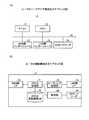
図2は、実施例2にかかるルータを含む情報管理システムの構成図である。図2に示した情報管理システム1は、VM(Virtual Machine)サービスデータセンタ2、通信事業者が提供するPPPoE(Point to Point Protocol over Ethernet(登録商標))網3、ルータ4、顧客用イントラネット5、及び顧客PC(Personal Computer)6を備えている。System Configuration FIG. 2 is a configuration diagram of an information management system including a router according to the second embodiment. The
PPPoEは、PPP(Point to Point Protocol)の機能をイーサネット(登録商標)を通して利用するプロトコルであり、後述する仮想私設通信網用のプロトコルである。PPPoE網3はワイドエリアネットワーク(WAN)である。ルータ4は、VMサービスデータセンタ2に接続するためのクラウドコンピューティング用のルータである。また、ルータ4は顧客PC6に直接接続されていてもよい。外部装置の一例として顧客PC6が挙げられる。 PPPoE is a protocol that uses the function of PPP (Point to Point Protocol) through Ethernet (registered trademark), and is a protocol for a virtual private communication network described later. The PPPoE network 3 is a wide area network (WAN). The
VMサービスデータセンタ2は、顧客PC6に対して、PPPoE網3経由でソフトウェアパッケージやアプリケーション実行用のプラットフォームなどのサービスを提供するクラウドコンピューティング用のサービスセンタである。また、VMサービスデータセンタ2は、物理サーバで構成される複数のIT(Information Technology)セル11と、ゲートウエイサーバで構成される複数のGW(Gateway)セル12と、管理サーバ14とを備えている。 The VM
管理サーバ14は、LAN(Local Area Network)13を介して複数のITセル11及び複数のGWセル12に接続されている。ITセル11は、情報処理装置の一例である。管理サーバ14は、情報管理装置の一例である。 The
ITセル11は、顧客PC6に提供するサービスを起動する仮想マシン17と、仮想マシン17からのデータの出力及び仮想マシン17へのデータの入力を制御する仮想ルータ18と備えている。仮想マシン17は、仮想ルータ18に1対1の関係で接続されている。また、ITセル11は、複数の仮想マシン17及び複数の仮想ルータ18を備えていてもよい。仮想マシン17は、仮想OSや、顧客へ提供するアプリケーションなどを起動している。仮想マシン17及び仮想ルータ18はソフトウエアで実現される。また、仮想ルータ18は、特定の顧客PCからのアクセスのみを受け付けるファイアーウォールルータである。 The
GWセル12は、ゲートウエイプログラムを有し、ゲートウエイプログラムを実行することにより、仮想ルータ18とPPPoE網3との間でデータの橋渡しを行う。 The
管理サーバ14は、ITセル管理部15(管理手段)と、ルータ管理部16とを備えている。ITセル管理部15は、データベース(DB)15Aを備えている。 The
図3は、データベース15Aの構成図である。データベース15Aには、ルータ4から受信するVM機器情報に関連付けられた、仮想マシン、仮想ルータ、ITセル及びGWセルのID番号が登録されている。VM機器情報は、仮想マシン17及び仮想モデム18を起動するITセル11を特定する情報であり、具体的には、ITセル11が有するOS(Operating System)及びITセル11が有するハードウエア資源の情報である。また、VM機器情報は、情報処理装置に関する情報の一例である。 FIG. 3 is a configuration diagram of the
図3の例では、OSは「windows server 2008」、「windows server 2000」及び「windows server 2007」である。ハードウエア資源は、「HDD 2TB, 2GB mem」、「HDD 1TB, 4GB mem」及び「HDD 2TB, 8GB mem」である。図3において、データベース15Aのセル15Bは「作成」となっている。これは、ITセル11が新たな仮想マシン17及び新たな仮想モデム18を作成することを示す。 In the example of FIG. 3, the OS is “
ITセル管理部15は、ルータ4からVM機器情報を受信すると、VM機器情報に基づいて、データベース15Aに登録されている仮想マシン17、仮想モデム18、ITセル11、及びGWセル12を選択する。ITセル管理部15は、選択したITセル11及びGWセル12を起動する。このとき、データベース15Aのセル15Bが「作成」になっている場合には、新たな仮想マシン17及び新たな仮想モデム18のID番号をデータベース15Aに登録し、新たな仮想マシン17及び新たな仮想モデム18を作成して起動する。 When receiving the VM device information from the
ITセル管理部15は、各ITセル11の動作を管理する。また、ルータ管理部16は、通信事業者が開設したIP-VPN(IP-Virtual Private Network)上で、ルータ4及びGWセル12との間のPPPoEセッションの通信を確立する。IP-VPNは、通信事業者の保有する広域IP通信網を経由して構築される仮想私設通信網(VPN)である。図2では、IP-VPNは、VMサービスデータセンタ2からPPPoE網3を介してルータ4まで接続する仮想私設通信網(VPN)である。IP-VPNの例としては、通信事業者が提供する、フレッツ・VPNワイドやFENICSビジネスIPネットワークサービスなどがある。 The IT
また、ルータ管理部16は、ルータ4に仮想ルータ18のIPアドレスを通知し、仮想ルータ18にルータ4のIPアドレスを通知し、ルータ4及び仮想ルータ18の間のEthernet over IPによる通信を確立する。さらに、ルータ管理部16は、ITセル管理部15に、仮想マシン17を起動するITセル11にPPPoEセッションの通信を実行するGWセル12を割り当てるように依頼する。ITセル管理部15及びルータ管理部16は、1台の管理サーバに含まれているが、別々のサーバに設けられていてもよい。 Further, the
通信事業者は、VMサービスデータセンタ2とルータ4との間で光通信(FTTH)のIP-VPNとしてのPPPoE網3を提供する。また、通信事業者は、遠隔地のコンピュータネットワークへ接続するためのサービスであるRAS20を有しており、このRAS20を使って、仮想ルータ18とルータ4との間のPPPoEセッションの通信を実行する。 The communication carrier provides the PPPoE network 3 as an IP-VPN for optical communication (FTTH) between the VM
図2の複数の仮想マシン17において、1つの仮想マシン17が、Webサーバ19を起動している。このWebサーバ19は、ルータ4からの要求を受けて仮想マシン17を構築し、提供する。 In the plurality of
ルータ4は、提供を希望する情報処理装置の処理能力、すなわちVM機器の設定を規定する情報を記録媒体から読み出して、Webサーバ19に送信する。具体的には、設定情報としては、VM機器のOSやハードウエア資源、例えばハードディスク容量やメモリ容量、アプリケーションが記録されている。利用者は、例えば希望に合致する情報を記録したSD(Secure Digital)カードを購入し、ルータ4に挿入することで、VM機器の設定を要求する。 The
ルータ4がSDカード7から読み出したVM機器情報は、Webサーバ19に通知され、Webサーバ19は、受信したVM機器情報をITセル管理部15に送信する。ITセル管理部15は、VM機器情報に基づいて、データベース15Aに登録されているITセル11及びGWセル12を起動する。ITセル管理部15は、新たな仮想マシン17及び新たな仮想モデム18のID番号をデータベース15Aに登録し、新たな仮想マシン17及び新たな仮想モデム18を作成し、起動する。 The VM device information read from the SD card 7 by the
以上のように構成された情報管理システム1では、顧客がルータ4をPPPoE網3と顧客用イントラネット5との間に接続し、SDカード7を挿入すると、VMサービスデータセンタ2は、顧客PC6が仮想マシン17を動作するITセル11を構築する。 In the
・装置の構成
図4(A)は、ITセル11のハードウエア構成を示すブロック図である。図4(B)は、管理サーバ14のルータ管理部16の機能構成を示すブロック図である。Device Configuration FIG. 4A is a block diagram showing a hardware configuration of the
図4(A)において、ITセル11は、装置全体を制御するCPU51、制御プログラムを備えるROM52、及びワーキングエリアとして機能するRAM53を備えている。また、ITセル11は、各種の情報やプログラムを備えるハードディスクドライブ(HDD)54、及びLAN13と接続するためのネットワークインタフェース55を備えている。 4A, the
CPU51は、システムバス56を介してROM52、RAM53、HDD54、及びネットワークインタフェース55に接続されている。ITセル11のハードウエア構成は、管理サーバ14及びGWセル12のハードウエア構成と同一であるので、管理サーバ14及びGWセル12のハードウエア構成の説明は省略する。尚、図2のITセル管理部15及びルータ管理部16は、管理サーバ14のCPU51が、管理サーバ14のROM52又はHDD54に格納されている制御プログラムを実行することによって実現される。また、図2のデータベース15Aは、管理サーバ14のHDD54に格納されている。 The
図4(B)において、ルータ管理部16は、受信部61、依頼部62、取得部63、指示部64、及び送信部65を備えている。 4B, the
受信部61は、ルータ4がPPPoE網3と顧客用イントラネット5との間に接続されたときに、VM機器情報をルータ4から受信する。依頼部62は、運用段階用のIP-VPNの作成、及び2組の運用段階用PPPoE設定情報の作成を通信事業者に依頼する。取得部63は、VM機器情報に基づいて、VMサービスデータセンタ2内の起動すべきITセル11、起動すべき仮想マシン17、起動すべき仮想ルータ18及び起動すべきGWセル12の情報を取得する。ここで、ITセル11の情報は、ITセル11を特定するID番号である。仮想マシン17の情報は、仮想マシン17を特定するID番号である。仮想ルータ18の情報は、仮想ルータ18を特定するID番号である。また、GWセル12の情報は、GWセル12を特定するID番号である。 The receiving
さらに、取得部63は、2組の運用段階用PPPoE設定情報を通信事業者から取得する。運用段階用PPPoE設定情報については、後述する。指示部64は、起動すべき仮想マシン17及び起動すべき仮想ルータ18の情報に対応する仮想マシン17及び仮想ルータ18の起動をITセル管理部15に指示する。送信部65は、1組の運用段階用PPPoE設定情報をルータ4へ送信し、他の1組の運用段階用PPPoE設定情報を、起動すべきGWセル12の情報に対応するGWセル12へ送信する。また、送信部65は、起動した仮想ルータ18のIPアドレスをルータ4に送信し、ルータ4のIPアドレスを起動した仮想ルータ18に送信する。 Furthermore, the
受信部61、取得部63及び送信部65は、管理サーバ14のCPU51及びネットワークインタフェース55により実現される。依頼部62及び指示部64は、管理サーバ14のCPU51が所定の制御プログラムを実行することにより実現される。 The
図5(A)は、ルータ4のハードウエア構成を示すブロック図である。図5(B)は、ルータ4の機能構成を示すブロック図である。 FIG. 5A is a block diagram illustrating a hardware configuration of the
図5(A)に示すように、ルータ4は、ルータ4の全体動作を制御するマイコン71、及び制御プログラムやデータを格納するメモリ72を備えている。また、ルータ4は、PPPoE網3と接続するためのWAN(Wide Area Network)側インターフェース73、及び顧客用イントラネット5と接続するためのLAN側インターフェース74を備えている。さらに、ルータ4は、SDカードリーダ76を備えている。マイコン71はバス75を介してメモリ72、WAN側インターフェース73、LAN側インターフェース74及びSDカードリーダ76に接続されている。 As shown in FIG. 5A, the
メモリ72は、仮想マシンに接続するためのスクリプト、設定段階用PPPoE設定情報、及びVM機器情報を格納している。設定段階用PPPoE設定情報は、PPPoEユーザ名とパスワードを含む。設定段階用PPPoE設定情報は、ルータ4がPPPoEを使って、PPPoE網3を介してVMサービスデータセンタ2に最初に接続するための情報である。PPPoEユーザ名は、例えば、「faucet-user-123456@facet.sop.fujitsu.com」であり、VMサービスデータセンタ2を特定するドメイン名及びルータ4の固有のIDで構成されている。また、メモリ72に格納されているVM機器情報は、Webサーバ19を起動しているITセル11を特定するVM機器情報である。従って、顧客PC6がルータ4を介して最初にアクセスする仮想マシン17は、Webサーバ19を起動する仮想マシン17である。 The
図5(B)に示すように、ルータ4は、PPPoE処理部77、ルーティング処理部78、PPPoE認証情報データベース(DB)79、WAN側インターフェース73及びLAN側インターフェース74を備えている。また、ルータ4は、要求部80とSDカードリーダ76を備えている。PPPoE認証情報DB79は、設定段階用PPPoE設定情報を格納している。また、PPPoE認証情報DB79は、メモリ72に格納されている。 As shown in FIG. 5B, the
PPPoE処理部77は、PPPoE認証情報DB79に格納された設定段階用PPPoE設定情報を使ってPPPoE網3を介してVMサービスデータセンタ2に最初に接続する処理を実行する。さらに、PPPoE処理部77は、運用段階用PPPoE設定情報を使ってPPPoE網3を介してVMサービスデータセンタ2に接続する処理を実行する。運用段階用PPPoE設定情報は、ルータ4を運用段階用のIP-PVNに接続するためのPPPoE−ID及びパスワードを含み、ルータ管理部16から取得される。運用段階用PPPoE設定情報は、仮想私設通信網用のプロトコルの設定情報の一例である。また、複数の顧客が設定段階時に同一のGWセル12を利用してVMサービスデータセンタ2にアクセスするため、ルータ管理部16は、運用段階時に顧客毎に別々のGWセル12を割り当てることで情報のセキュリティを高めている。このため、設定段階用PPPoE設定情報と運用段階用PPPoE設定情報とを分けている。 The
ルーティング処理部78は、ITセル管理部15で選択された仮想ルータ18のIPアドレスをルータ管理部16から取得し、ITセル管理部15で選択された仮想ルータ18と、Ethernet over IPによる通信を行う。これにより、Ethernet over IPによるデータ通信が顧客PC6とITセル管理部15で選択された仮想マシン17との間で実行される。Ethernet over IPは、データ(具体的にはイーサフレーム)をIPパケット化し送受信する機能である。PPPoE処理部77及びルーティング処理部78は、マイコン71がメモリ72に格納されている制御プログラムを実行することにより実現される。 The
・処理の説明
図6は、ルータ4が実行する処理を示すフローチャートである。前提として、顧客がルータ4のWAN側インターフェース73に光通信ケーブルを接続し、LAN側インターフェース74にLANケーブルを接続し、ルータ4の電源を投入しているものとする。Processing Description FIG. 6 is a flowchart showing processing executed by the
まず、PPPoE処理部77が、PPPoE認証情報DB79に格納された設定段階用PPPoE設定情報を使って設定段階のPPPoEによるGWセル12への通信路を開設する、即ち設定段階用のIP-VPNに接続する(ステップS1)。ステップS1により、ルータ4は、PPPoE網3を介してVMサービスデータセンタ2のGWセル12にアクセスする。 First, the
次いで、PPPoE処理部77は、接続開始を通知するための情報及びPPPoE認証情報DB79に格納されたVM機器情報をルータ管理部16に送信する(ステップS2)。接続開始を通知するための情報は、例えば、接続開始を示すパケットである。また、ルータ管理部16のホスト名が「faucet-mng.cloud.fujitsu.com」である場合には、PPPoE処理部77は、接続開始を示すパケット及びVM機器情報を宛先「http://faucet-mng.cloud.fujitsu.com」に送信する。ステップS2で送信されるVM機器情報は、Webサーバ19を起動しているITセル11を特定するVM機器情報である。 Next, the
次に、PPPoE処理部77は、VM機器情報の返信として、運用段階用PPPoE設定情報、即ち、PPPoE−ID及びパスワードをルータ管理部16から取得する(ステップS3)。PPPoE処理部77は、ルータ管理部16から取得したPPPoE−ID及びパスワードを用いて、運用段階のPPPoEによる、起動したGWセル12への通信路を開設する、即ち運用段階用のIP-VPNに接続する(ステップS4)。ステップS4により、ルータ4は、イーサネットを使った仮想私設通信網で、起動したGWセル12と接続できる。 Next, the
その後、ルーティング処理部78は、ITセル管理部15で選択された仮想ルータ18のIPアドレスをルータ管理部16から取得する(ステップS5)。例えば、ルーティング処理部78は、ルータ管理部16内の仮想ルータ18のIPアドレスの登録先「http://faucet-mng.cloud.fujitsu.com/etherip-param」からITセル管理部15で選択された仮想ルータ18のIPアドレスを取得する。ここで、ITセル管理部15で選択された仮想ルータ18のIPアドレスは、Webサーバ19を起動しているITセル11に接続される仮想ルータ18のIPアドレスである。 Thereafter, the
ルーティング処理部78は、Ethernet over IP機能、即ちデータをIPパケット化し、ITセル管理部15で選択された仮想ルータ18との間でIPパケットを送受信する機能を設定する。これにより、ルータ4があたかもイーサネットで、ITセル管理部15で選択された仮想ルータ18に接続される仮想マシン17、即ちWebサーバ19に直接つながっている状態を作成できる。同時に、ルーティング処理部78は、取得した仮想ルータ18のIPアドレスに基づいて、起動したGWセル12からルータ4までの通信路を介してITセル管理部15で選択された仮想ルータ18と通信する(ステップS6)。尚、ルータ4は、DHCP(Dynamic Host Configuration Protocol)を有し、顧客PC6にIPアドレスを割り当てるので、Webサーバ19を起動する仮想マシン17は、仮想ルータ18及びルータ4を介して顧客PC6に接続される。また、ルータ4は、ルータ4のIPアドレスを顧客PC6のIPアドレスに割り当てるテーブル情報等を有していれば、DHCPを有してなくてもよい。 The
ステップS1〜S6の工程により、顧客PC6は、ルータ4、PPPoE網3(IP-VPN)、GWセル12及び仮想ルータ18を介してEthernet over IPによりWebサーバ19にアクセスすることができる。 Through the steps S1 to S6, the
次に、ルータ4のSDカードリーダ76にSDからVM機器情報を読み出し(ステップS7)、読み出したVM機器情報を要求部80がWebサーバ19に送信する(ステップS8)。 Next, the VM device information is read from the SD to the
ルーティング処理部78は、VM機器情報に基づいて新たに起動した仮想ルータ18のIPアドレスをルータ管理部16に定期的に問い合わせ、仮想ルータ18のIPアドレスをルータ管理部16から取得する(ステップS9)。ここで、新たに起動された仮想ルータ18がない場合には、ルーティング処理部78は、新たに起動された仮想ルータ18がないことを示す情報をルータ管理部16から取得する。 The
ルーティング処理部78は、Ethernet over IP機能を設定し、ステップS9で取得した仮想ルータ18のIPアドレスに基づいて、当該仮想ルータ18と通信する(ステップS10)。その後、ステップS8に戻る。 The
ステップS7〜S10の工程により、顧客PC6は、SDカードから読み出されたVM機器情報に基づいて新たに起動した仮想マシン17とEthernet over IPにより通信することができる。また、ステップS8〜S10の工程が繰り返されることで、顧客PC6は、新たに起動した複数の仮想マシン17とEthernet over IPにより通信することができる。 Through the steps S7 to S10, the
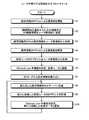
図7は、ルータ管理部16が実行する処理を示すフローチャートである。受信部61は、接続開始を示すパケット及びVM機器情報をルータ4から受信する(ステップS11)。取得部63は、VM機器情報をITセル管理部15に送信する。そして、取得部63は、起動すべき仮想マシン、起動すべき仮想ルータ、起動すべきITセルの情報及び起動すべきGWセルの情報をITセル管理部15から取得する(ステップS12)。ここで、起動すべき仮想マシンは、Webサーバ19を起動する仮想マシン17である。また、起動すべき仮想ルータは、Webサーバ19を起動する仮想マシン17に接続されている仮想ルータ18である。さらに、起動すべきITセルは、Webサーバ19を起動する仮想マシン17を含むITセル11である。 FIG. 7 is a flowchart showing processing executed by the
依頼部62は、運用段階用のIP-VPNの作成、及び2組の運用段階用PPPoE設定情報の作成を通信事業者に依頼する(ステップS13)。ここでは、依頼部62は、通信事業者のサイト(例えば「フレッツ光ネクスト サービス申込受付ページ フレッツ VPN・ワイド設定メニュー」)にアクセスして、依頼を実行する。尚、ステップS13の工程は、VMサービスデータセンタ2の管理者が運用段階用のIP-VPNの作成、及び2組の運用段階用PPPoE設定情報の作成を通信事業者に依頼してもよい。その後、通信事業者が運用段階用のIP-VPNを作成する。 The
取得部63は、2組の運用段階用PPPoE設定情報を通信事業者から取得する(ステップS14)。次いで、送信部65は、1組の運用段階用PPPoE設定情報をルータ4に送信する(ステップS15)。ステップS15により、ルータ4のPPPoE処理部77が運用段階用PPPoE設定情報を使って、ステップS12で取得されたGWセルの情報に対応するGWセル12への通信路を開設する。送信部65は、他の1組の運用段階用PPPoE設定情報を、ステップS12で取得されたGWセルの情報に対応するGWセルに送信する(ステップS16)。ステップS16により、ステップS12で取得されたGWセルの情報に対応するGWセル12が、運用段階用PPPoE設定情報を使って、ルータ4への通信路を開設する。 The
指示部64は、ステップS12で取得した、起動すべき仮想マシン17及び起動すべき仮想ルータ18の情報に対応する仮想マシン17及び仮想ルータ18の起動をITセル管理部15に指示する(ステップS17)。その後、送信部65は、起動した仮想ルータ18のIPアドレスをルータ4に送信し、ルータ4のIPアドレスを、起動した仮想ルータ18に送信する(ステップS18)。ステップS18により、起動した仮想ルータ18は、Ethernet over IP機能、即ちデータをIPパケット化し送受信する機能を設定する。そして、起動した仮想ルータ18は、ルータ4のIPアドレスに基づいて、GWセル12からルータ4までの通信路を介してルータ4と通信する。また、ルータ4は、Ethernet over IP機能、即ちデータをIPパケット化し送受信する機能を設定する。そして、ルータ4は、仮想ルータ18のIPアドレスに基づいて、GWセル12からルータ4までの通信路を介して起動した仮想ルータ18と通信する。 The
ステップS11〜S18の工程により、ルータ管理部16は、顧客PC6がルータ4、PPPoE網3(IP-VPN)、GWセル12及び仮想ルータ18を介してWebサーバ19を起動する仮想マシン17にアクセスすることを補助することができる。 Through the steps S11 to S18, the
次に、送信部65は、ルータから指定されたVM機器情報に基づいて新たに起動した仮想ルータ18のIPアドレスをルータ4に送信する。さらに、送信部65は、ルータ4のIPアドレスを当該新たに起動した仮想ルータ18に送信する(ステップS19)。ステップS19により、新たに起動した仮想ルータ18は、Ethernet over IP機能、即ちデータをIPパケット化し送受信する機能を設定する。そして、新たに起動した仮想ルータ18は、ルータ4のIPアドレスに基づいて、GWセル12からルータ4までの通信路を介してルータ4と通信する。また、ルータ4は、Ethernet over IP機能、即ちデータをIPパケット化し送受信する機能を設定する。そして、ルータ4は、新たに起動した仮想ルータ18のIPアドレスに基づいて、GWセル12からルータ4までの通信路を介して新たに起動した仮想ルータ18と通信する。 Next, the
ステップS19の工程により、ルータ管理部16は、顧客PC6がルータ4、PPPoE網3(IP-VPN)、GWセル12及び仮想ルータ18を介して新たに起動した仮想マシン17にアクセスすることを補助することができる。 In step S19, the
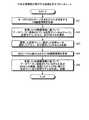
図8は、ITセル管理部15が実行する処理を示すフローチャートである。まず、ITセル管理部15は、ルータ4からルータ管理部16を介してWebサーバ19を含むITセル11を特定するVM機器情報を受信する(ステップS21)。ITセル管理部15は、受信したVM機器情報に基づいて、データベース15Aに登録されている仮想マシン17、仮想モデム18、ITセル11、及びGWセル12を選択する(ステップS22)。ここで、選択した仮想マシン17は、Webサーバ19を起動する仮想マシンである。選択した仮想ルータ18は、Webサーバ19を起動する仮想マシン17に接続された仮想ルータである。選択したITセル11は、Webサーバ19を起動する仮想マシン及びその仮想マシンに接続された仮想ルータを含むITセルである。ITセル管理部15は、選択した仮想マシン17、選択した仮想ルータ18、選択したITセル11、及び選択したGWセル12を起動する(ステップS23)。 FIG. 8 is a flowchart showing processing executed by the IT
次いで、ITセル管理部15は、ルータ4からWebサーバ19を含むITセル11を介してVM機器情報を受信する(ステップS24)。このVM機器情報は、ルータ4がSDカードから読みだしたVM機器情報である。ITセル管理部15は、受信したVM機器情報に基づいて、データベース15Aに登録されているITセル11及びGWセル12を起動する。そして、ITセル管理部15は、起動したITセル11内に新たに仮想マシン17及び仮想モデム18を作成し、起動する(ステップS25)。 Next, the IT
本処理によれば、ITセル管理部15は、Webサーバ19を含むITセル11を特定するVM機器情報に基づいて、Webサーバ19を起動する仮想マシン17を起動するので、ルータ4からVM機器情報を受信することができる。また、ITセル管理部15は、ルータ4がSDカードから読み出したVM機器情報に基づいて新たな仮想マシン及び新たな仮想モデムを作成し、起動することができる。 According to this process, the IT
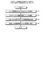
図9は、Webサーバ19を起動する仮想マシン17を有するITセル11が実行する処理を示すフローチャートである。尚、Webサーバ19を起動する仮想マシン17及び仮想ルータ18を有するITセル11が起動しているものとする。 FIG. 9 is a flowchart showing processing executed by the
ITセル11内の仮想ルータ18は、ルータ管理部16からルータ4のIPアドレスを受信する(ステップS31)。仮想ルータ18は、Ethernet over IP機能、即ちデータをIPパケット化し送受信する機能を設定する。そして、仮想ルータ18は、ルータ4のIPアドレスに基づいて、GWセル12からルータ4までの通信路を介してルータ4と通信する(ステップS32)。 The
Webサーバ19は、ルータ4からVM機器情報を取得する(ステップS33)。Webサーバ19は、VM機器情報をITセル管理部15に送信する(ステップS34)。これにより、ITセル管理部15は、受信したVM機器情報に基づいて、データベース15Aに登録されているITセル11及びGWセル12を選択し、選択したITセル11内に新たに仮想マシン17及び仮想モデム18を作成し、起動する。 The
ここで、第1送信手段、取得手段及び第2送信手段の一例は、ステップS33〜S34を実行するWebサーバ19である。Webサーバ19は、ITセル11のCPU51が所定のソフトウエア(例えば、仮想マシン用アプリケーション)を実行することで実現される。 Here, an example of the first transmission unit, the acquisition unit, and the second transmission unit is the
図10及び図11は、情報管理システム1が実行する処理のシーケンスを示す図である。まず、ルータ4の工場出荷時に、ルータ4のメモリ72には、Webサーバ19を起動する仮想マシン17を含むITセル11を特定するVM機器情報が設定されている(ステップS41)。次に、ルータ4の接続時に、ルータ4のPPPoE処理部77は、PPPoE認証情報DB79に格納された設定段階用PPPoE設定情報を使って設定段階のPPPoEによるGWセル12への通信路を開設する(ステップS42)。ルータ4のPPPoE処理部77は、接続開始を示すパケット及びVM機器情報をルータ管理部16に送信する(ステップS43)。 10 and 11 are diagrams showing a sequence of processing executed by the
ルータ管理部16は、接続開始を示すパケット及びVM機器情報をルータ4から受信する(ステップS44)。ルータ管理部16は、VM機器情報をITセル管理部15に送信する(ステップS45)。ITセル管理部15は、VM機器情報を受信し、起動すべき仮想マシン17、起動すべき仮想ルータ18、起動すべきITセル11及び起動すべきGWセル12を選択する(ステップS46)。起動すべき仮想マシン17は、Webサーバ19を起動する仮想マシンである。 The
そして、ルータ管理部16は、起動すべき仮想マシン17、起動すべき仮想ルータ18、起動すべきITセル11及び起動すべきGWセル12の情報をITセル管理部15から取得する(ステップS47)。ルータ管理部16は、運用段階用のIP-VPNの作成、及び2組の運用段階用PPPoE設定情報の作成を通信事業者に依頼する(ステップS48)。通信事業者は、ルータ管理部16からの依頼に応じて運用段階用のIP-VPNを開設し、2組の運用段階用PPPoE設定情報をルータ管理部16に返信する。ルータ管理部16は、1組の運用段階用PPPoE設定情報をルータ4に、他の1組の運用段階用PPPoE設定情報を、起動すべきGWセルに送信する(ステップS49)。 Then, the
ルータ4のPPPoE処理部77は、運用段階用PPPoE設定情報を使って、起動すべきGWセル12への通信路を開設する(ステップS50)。また、起動すべきGWセル12が、運用段階用PPPoE設定情報を使って、ルータ4への通信路を開設する(ステップS51)。ステップS50,S51により、ルータ4及び起動すべきGWセル12は、イーサネットを使った仮想私設通信網を介して互いに接続できる。 The
次に、ルータ管理部16は、ステップS47で取得した起動すべき仮想マシン17及び起動すべき仮想ルータ18の情報に対応する仮想マシン17及び仮想ルータ18の起動をITセル管理部15に指示する(ステップS52)。ITセル管理部15は、起動すべきITセル11に、起動すべき仮想マシン17、即ちWebサーバ19を起動する仮想マシン17、及び起動すべき仮想ルータ18を起動させる(ステップS53)。ITセル管理部15で選択されたITセル11は、Webサーバ19を起動する仮想マシン17及び起動すべき仮想ルータ18を起動する(ステップS54)。 Next, the
その後、ルータ管理部16は、起動した仮想ルータ18のIPアドレスをルータ4へ、ルータ4のIPアドレスを起動した仮想ルータ18へそれぞれ送信する(ステップS55)。ルータ4は、起動した仮想ルータ18のIPアドレスをルータ管理部16から受信する。ルータ4は、Ethernet over IP機能を設定し、受信されたIPアドレスに基づいて、GWセル12からルータ4までの通信路を介して起動した仮想ルータ18と通信する(ステップS56)。ITセル11内の起動した仮想ルータ18は、ルータ管理部16からルータ4のIPアドレスを受信する。起動した仮想ルータ18は、Ethernet over IP機能、即ちデータをIPパケット化し送受信する機能を設定する。同時に、起動した仮想ルータ18は、受信されたIPアドレスに基づいて、GWセル12からルータ4までの通信路を介してルータ4と通信する(ステップS57)。 Thereafter, the
ステップS41〜S57の工程により、顧客PC6は、Webサーバ19を起動する仮想マシン17と通信可能になる。 Through the steps S41 to S57, the
次に、ルータ4は、SDカードからVM機器情報を読み出し、選択したVM機器情報を、Webサーバ19を起動する仮想マシン17に返信する(ステップS58)。 Next, the
Webサーバ19は、SDカードから読み出されたVM機器情報を取得する(ステップS59)。Webサーバ19は、取得したVM機器情報をITセル管理部15に送信する(ステップS60)。ITセル管理部15は、受信したVM機器情報に基づいて、データベース15Aに登録されているITセル11及びGWセル12を起動する。そして、ITセル管理部15は、起動したITセル11内に新たに仮想マシン17及び仮想モデム18を作成し、起動させる(ステップS61)。これにより、新たな仮想マシン17及び新たな仮想モデム18が起動する(ステップS62)。 The
その後、ルータ管理部16は、新たに起動した仮想ルータ18のIPアドレスをルータ4へ、ルータ4のIPアドレスを新たに起動した仮想ルータ18へそれぞれ送信する(ステップS63)。ルータ4は、新たに起動した仮想ルータ18のIPアドレスをルータ管理部16から受信する。ルータ4は、Ethernet over IP機能を設定し、受信されたIPアドレスに基づいて、新たに起動した仮想ルータ18と通信する(ステップS64)。ITセル11内の新たに起動した仮想ルータ18は、ルータ管理部16からルータ4のIPアドレスを受信する。新たに起動した仮想ルータ18は、Ethernet over IP機能を設定し、受信されたIPアドレスに基づいて、ルータ4と通信する(ステップS65)。 Thereafter, the
ステップS58〜S65の工程により、顧客PC6は、SDカードからよみだされたVM機器情報に対応する新たな仮想マシン17と通信可能になる。 By the steps S58 to S65, the
・実施例2のまとめ
上述してきたように本実施例2によれば、ルータ4がPPPoE網3と顧客PC6との間に接続されたときに、ITセル11内の仮想マシン17上で起動するWebサーバ19が、SDカードに記録されたVM機器情報をルータ4から受信し、VM機器情報に基づいて新たな仮想マシン及び仮想モデムを作成し起動するITセル管理部15に送信する。よって、顧客PC6の使用者がルータ4の設置後に新たに起動する仮想マシン及び仮想モデムをSDカードの選択によって選ぶことができる。-Summary of
Webサーバ19を含むITセル11の機能を実現するためのプログラムが記録されている記録媒体を、ITセル11に供給し、ITセル11のCPU51が記憶媒体に格納されたプログラムを実行してもよい。また、ITセル管理部15又はルータ管理部16の機能を実現するためのプログラムが記録されている記録媒体を、管理サーバ14に供給し、管理サーバ14のCPU51が記憶媒体に格納されたプログラムを実行してもよい。プログラムを供給するための記憶媒体としては、例えば、CD−ROM(Compact Disk Read Only Memory)、DVD(Digital Versatile Disk)、又はSD(Secure Digital)メモリカードなどがある。 Even if a recording medium on which a program for realizing the functions of the
また、ITセル11のCPU51が、Webサーバ19、仮想マシン17及び仮想ルータ18の機能を実現するためのソフトウェアのプログラムを実行することによっても、上記実施の形態と同様の効果を奏する。管理サーバ14のCPU51が、ITセル管理部15又はルータ管理部16の機能を実現するためのソフトウェアのプログラムを実行することによっても、上記実施の形態と同様の効果を奏する。 The
1 情報管理システム
2 VM(Virtual Machine)サービスデータセンタ
3 PPPoE(Point to Point Protocol over Ethernet)網
4,101 ルータ
5 顧客用イントラネット
6 顧客PC(Personal Computer)
7 SDカード
11 IT(Information Technology)セル
12 GW(Gateway)セル
14 管理サーバ
13 LAN(Local Area Network)
17 仮想マシン
18 仮想ルータ
19 Webサーバ
100 ネットワーク
102 読み出し部
103 要求部
104 ルーティング部
111 作成装置
112 提供装置
113 外部装置DESCRIPTION OF
7
17
Claims (9)
Translated fromJapanese前記仮想私設通信網を介して前記外部装置と通信する情報処理装置の処理能力を規定する情報を記録媒体から読み出す読み出し部と、
前記読み出し部が読み出した情報を送出して前記処理能力の規定を満たす情報処理装置の提供を要求する要求部と、
を備えたことを特徴とするルータ。A routing unit that performs routing between the virtual private communication network and the external device;
A reading unit that reads information defining the processing capability of an information processing device that communicates with the external device via the virtual private communication network from a recording medium;
A requesting unit for requesting provision of an information processing apparatus that sends out information read by the reading unit and satisfies the processing capacity;
A router characterized by comprising:
読み出した情報を送出して前記処理能力の規定を満たす情報処理装置の提供を要求するステップと、
前記仮想私設通信網と前記外部装置との間でルーティングして前記外部装置と前記情報処理装置との通信を中継するステップと
を含んだことを特徴とするルーティング方法。Reading out information defining the processing capability of an information processing device that communicates with an external device via a virtual private communication network from a recording medium;
Sending out the read information and requesting the provision of an information processing apparatus that satisfies the processing capability regulations; and
A routing method comprising: routing between the virtual private communication network and the external device to relay communication between the external device and the information processing device.
読み出した情報を送出して前記処理能力の規定を満たす情報処理装置の提供を要求する手順と、
前記仮想私設通信網と前記外部装置との間でルーティングして前記外部装置と前記情報処理装置との通信を中継する手順と
をコンピュータに実行させることを特徴とするルーティングプログラム。A procedure for reading out information defining the processing capability of an information processing device that communicates with an external device via a virtual private communication network from a recording medium;
A procedure for requesting provision of an information processing apparatus that sends out the read information and satisfies the processing capability regulations;
A routing program that causes a computer to execute a procedure of routing between the virtual private communication network and the external device and relaying communication between the external device and the information processing device.
前記情報が規定する処理能力を満たす仮想マシンを構築する仮想マシン管理部と、
前記仮想マシンに関する情報を前記ルータに送信する送信部と
を備えたことを特徴とする情報処理装置。A receiving unit that receives information defining the processing capability of an information processing device provided to an external device connected via the router from a router connected via a virtual private communication network;
A virtual machine management unit that constructs a virtual machine that satisfies the processing capability defined by the information;
An information processing apparatus comprising: a transmission unit that transmits information about the virtual machine to the router.
前記情報が規定する処理能力を満たす仮想マシンを構築するステップと、
前記仮想マシンに関する情報を前記ルータに送信するステップと
を含んだことを特徴とする仮想マシン構築方法。Receiving information defining the processing capability of an information processing device provided to an external device connected via the router from a router connected via a virtual private communication network;
Constructing a virtual machine satisfying the processing capability defined by the information;
And a step of transmitting information related to the virtual machine to the router.
前記情報が規定する処理能力を満たす仮想マシンを構築する手順と、
前記仮想マシンに関する情報を前記ルータに送信する手順と
をコンピュータに実行させることを特徴とする仮想マシン構築プログラム。A procedure for receiving information defining the processing capability of an information processing device provided to an external device connected via the router from a router connected via a virtual private communication network;
A procedure for constructing a virtual machine satisfying the processing capability defined by the information;
A virtual machine construction program for causing a computer to execute a procedure for transmitting information on the virtual machine to the router.
Priority Applications (2)
| Application Number | Priority Date | Filing Date | Title |
|---|---|---|---|
| JP2010021666AJP2011160300A (en) | 2010-02-02 | 2010-02-02 | Router, routing method, routing program, information processing apparatus, and method and program of constructing virtual machine |
| US13/016,455US20110191492A1 (en) | 2010-02-02 | 2011-01-28 | Router, routing method, information processing apparatus, and method of constructing virtual machine |
Applications Claiming Priority (1)
| Application Number | Priority Date | Filing Date | Title |
|---|---|---|---|
| JP2010021666AJP2011160300A (en) | 2010-02-02 | 2010-02-02 | Router, routing method, routing program, information processing apparatus, and method and program of constructing virtual machine |
Publications (1)
| Publication Number | Publication Date |
|---|---|
| JP2011160300Atrue JP2011160300A (en) | 2011-08-18 |
Family
ID=44342608
Family Applications (1)
| Application Number | Title | Priority Date | Filing Date |
|---|---|---|---|
| JP2010021666APendingJP2011160300A (en) | 2010-02-02 | 2010-02-02 | Router, routing method, routing program, information processing apparatus, and method and program of constructing virtual machine |
Country Status (2)
| Country | Link |
|---|---|
| US (1) | US20110191492A1 (en) |
| JP (1) | JP2011160300A (en) |
Cited By (3)
| Publication number | Priority date | Publication date | Assignee | Title |
|---|---|---|---|---|
| JP2012075070A (en)* | 2010-09-30 | 2012-04-12 | Fujitsu Ltd | Management program, device and method, router, and information processing program and method |
| JP2013012865A (en)* | 2011-06-29 | 2013-01-17 | Fujitsu Ltd | Information processor, information processing program, and management method |
| JP2014093550A (en)* | 2012-10-31 | 2014-05-19 | Fujitsu Ltd | Management server, virtual machine system, program and connection method |
Families Citing this family (9)
| Publication number | Priority date | Publication date | Assignee | Title |
|---|---|---|---|---|
| US20130132948A1 (en)* | 2011-11-21 | 2013-05-23 | Adiseshu Hari | Personal cloud computing and virtual distributed cloud computing system |
| US10387201B2 (en)* | 2012-06-26 | 2019-08-20 | Vmware, Inc. | Storage performance-based virtual machine placement |
| US9148350B1 (en) | 2013-03-11 | 2015-09-29 | Amazon Technologies, Inc. | Automated data synchronization |
| US10313345B2 (en) | 2013-03-11 | 2019-06-04 | Amazon Technologies, Inc. | Application marketplace for virtual desktops |
| US9002982B2 (en)* | 2013-03-11 | 2015-04-07 | Amazon Technologies, Inc. | Automated desktop placement |
| US10142406B2 (en) | 2013-03-11 | 2018-11-27 | Amazon Technologies, Inc. | Automated data center selection |
| US10623243B2 (en) | 2013-06-26 | 2020-04-14 | Amazon Technologies, Inc. | Management of computing sessions |
| US10686646B1 (en) | 2013-06-26 | 2020-06-16 | Amazon Technologies, Inc. | Management of computing sessions |
| US9294524B2 (en)* | 2013-12-16 | 2016-03-22 | Nicira, Inc. | Mapping virtual machines from a private network to a multi-tenant public datacenter |
Citations (3)
| Publication number | Priority date | Publication date | Assignee | Title |
|---|---|---|---|---|
| JP2009100062A (en)* | 2007-10-13 | 2009-05-07 | A2 Network Kk | Communication method |
| WO2009093333A1 (en)* | 2008-01-25 | 2009-07-30 | Fujitsu Limited | Information processing device, information processing system, computer program, and information processing method |
| JP2009301515A (en)* | 2008-06-10 | 2009-12-24 | 2Xalpha Solutions Co Ltd | Thin client connection apparatus |
Family Cites Families (18)
| Publication number | Priority date | Publication date | Assignee | Title |
|---|---|---|---|---|
| US6124806A (en)* | 1997-09-12 | 2000-09-26 | Williams Wireless, Inc. | Wide area remote telemetry |
| JP3467226B2 (en)* | 2000-04-20 | 2003-11-17 | 埼玉日本電気株式会社 | Mobile phone system |
| CN1224914C (en)* | 2000-08-25 | 2005-10-26 | 四国电力株式会社 | Remote control server, center server, and system constituted of them |
| US7228337B1 (en)* | 2001-09-11 | 2007-06-05 | Cisco Technology, Inc. | Methods and apparatus for providing a network service to a virtual machine |
| US7379982B2 (en)* | 2002-04-15 | 2008-05-27 | Bassam Tabbara | System and method for custom installation of an operating system on a remote client |
| JP3941014B2 (en)* | 2002-12-02 | 2007-07-04 | ソニー株式会社 | Information processing system and information processing apparatus |
| KR100533835B1 (en)* | 2004-01-26 | 2005-12-07 | 삼성전자주식회사 | Network printer system and managing method for toner cartridge thereof |
| US7802000B1 (en)* | 2005-08-01 | 2010-09-21 | Vmware | Virtual network in server farm |
| JP4653697B2 (en)* | 2006-05-29 | 2011-03-16 | 株式会社日立製作所 | Power management method |
| US8381209B2 (en)* | 2007-01-03 | 2013-02-19 | International Business Machines Corporation | Moveable access control list (ACL) mechanisms for hypervisors and virtual machines and virtual port firewalls |
| JP4881169B2 (en)* | 2007-01-23 | 2012-02-22 | 株式会社バッファロー | Storage power supply system, storage device, and control method and control program therefor |
| EP2015174B1 (en)* | 2007-06-21 | 2018-03-14 | Imsys AB | Microprogrammed processor having multiple processor cores using time-shared access to a microprogram control store |
| US8191063B2 (en)* | 2007-09-30 | 2012-05-29 | Symantex Corporation | Method for migrating a plurality of virtual machines by associating files and state information with a single logical container |
| US7801994B2 (en)* | 2007-11-29 | 2010-09-21 | Hitachi, Ltd. | Method and apparatus for locating candidate data centers for application migration |
| US8676904B2 (en)* | 2008-10-02 | 2014-03-18 | Apple Inc. | Electronic devices with voice command and contextual data processing capabilities |
| JP2010134629A (en)* | 2008-12-03 | 2010-06-17 | Sony Corp | Information processing apparatus and method |
| JP5419895B2 (en)* | 2008-12-26 | 2014-02-19 | パナソニック株式会社 | Communication device |
| US8705513B2 (en)* | 2009-12-15 | 2014-04-22 | At&T Intellectual Property I, L.P. | Methods and apparatus to communicatively couple virtual private networks to virtual machines within distributive computing networks |
- 2010
- 2010-02-02JPJP2010021666Apatent/JP2011160300A/enactivePending
- 2011
- 2011-01-28USUS13/016,455patent/US20110191492A1/ennot_activeAbandoned
Patent Citations (3)
| Publication number | Priority date | Publication date | Assignee | Title |
|---|---|---|---|---|
| JP2009100062A (en)* | 2007-10-13 | 2009-05-07 | A2 Network Kk | Communication method |
| WO2009093333A1 (en)* | 2008-01-25 | 2009-07-30 | Fujitsu Limited | Information processing device, information processing system, computer program, and information processing method |
| JP2009301515A (en)* | 2008-06-10 | 2009-12-24 | 2Xalpha Solutions Co Ltd | Thin client connection apparatus |
Cited By (4)
| Publication number | Priority date | Publication date | Assignee | Title |
|---|---|---|---|---|
| JP2012075070A (en)* | 2010-09-30 | 2012-04-12 | Fujitsu Ltd | Management program, device and method, router, and information processing program and method |
| JP2013012865A (en)* | 2011-06-29 | 2013-01-17 | Fujitsu Ltd | Information processor, information processing program, and management method |
| JP2014093550A (en)* | 2012-10-31 | 2014-05-19 | Fujitsu Ltd | Management server, virtual machine system, program and connection method |
| US9413595B2 (en) | 2012-10-31 | 2016-08-09 | Fujitsu Limited | Management server, virtual machine system, computer-readable recording medium, and connection method |
Also Published As
| Publication number | Publication date |
|---|---|
| US20110191492A1 (en) | 2011-08-04 |
Similar Documents
| Publication | Publication Date | Title |
|---|---|---|
| JP2011160300A (en) | Router, routing method, routing program, information processing apparatus, and method and program of constructing virtual machine | |
| JP5482453B2 (en) | Router, information processing apparatus, and program | |
| JP6118850B2 (en) | Provide access to a configurable private computer network | |
| JP6403800B2 (en) | Migrating applications between enterprise-based and multi-tenant networks | |
| US8856786B2 (en) | Apparatus and method for monitoring communication performed by a virtual machine | |
| CN103916378B (en) | System and method for automatically deploying application system in cloud resource pool | |
| JP5998248B2 (en) | How to provide local secure network access to remote services | |
| JP4621405B2 (en) | Method and system for managing virtual addresses of virtual networks | |
| US9521053B1 (en) | Providing diagnostic metrics for virtual connections over physical connections into a provider network | |
| US11388261B2 (en) | Cross-domain brokering protocol cloud proxy | |
| US20180159792A1 (en) | Methods and systems for creating and managing network groups | |
| US20130014106A1 (en) | Information processing apparatus, computer-readable medium storing information processing program, and management method | |
| JP2011160298A (en) | Network system, process-providing-server switching method, process-providing-server switching program, information processing apparatus, virtual machine building method, and virtual machine building program | |
| CN101218577A (en) | Unified Architecture for Remote Network Access | |
| US9577982B2 (en) | Method and apparatus for extending remote network visibility of the push functionality | |
| JP5854138B2 (en) | Information processing system, information processing method, and communication device | |
| US20120084389A1 (en) | Technique for providing service through data center | |
| KR20130130755A (en) | Dns forwarder for multi-core platforms | |
| JP2011248690A (en) | Device and program for processing information | |
| JP6636971B2 (en) | Communication method and communication system | |
| Chaitra et al. | Integration of software router with Wi-Fi for enhanced security | |
| CN110990149B (en) | A load balancing test method based on ICOS system | |
| JP2013021423A (en) | Vpn connection system and connection method thereof and program thereof | |
| JP6973326B2 (en) | Communication system and communication method | |
| Sabale et al. | Implement and Manage Networking for Azure Virtual Desktop |
Legal Events
| Date | Code | Title | Description |
|---|---|---|---|
| A621 | Written request for application examination | Free format text:JAPANESE INTERMEDIATE CODE: A621 Effective date:20121005 | |
| A977 | Report on retrieval | Free format text:JAPANESE INTERMEDIATE CODE: A971007 Effective date:20130712 | |
| A131 | Notification of reasons for refusal | Free format text:JAPANESE INTERMEDIATE CODE: A131 Effective date:20130730 | |
| A02 | Decision of refusal | Free format text:JAPANESE INTERMEDIATE CODE: A02 Effective date:20131203 |