JP2011153583A - Supercharger - Google Patents
SuperchargerDownload PDFInfo
- Publication number
- JP2011153583A JP2011153583AJP2010016171AJP2010016171AJP2011153583AJP 2011153583 AJP2011153583 AJP 2011153583AJP 2010016171 AJP2010016171 AJP 2010016171AJP 2010016171 AJP2010016171 AJP 2010016171AJP 2011153583 AJP2011153583 AJP 2011153583A
- Authority
- JP
- Japan
- Prior art keywords
- turbine
- rotation
- compressor
- rotating element
- impeller
- Prior art date
- Legal status (The legal status is an assumption and is not a legal conclusion. Google has not performed a legal analysis and makes no representation as to the accuracy of the status listed.)
- Pending
Links
Images


Classifications
- Y—GENERAL TAGGING OF NEW TECHNOLOGICAL DEVELOPMENTS; GENERAL TAGGING OF CROSS-SECTIONAL TECHNOLOGIES SPANNING OVER SEVERAL SECTIONS OF THE IPC; TECHNICAL SUBJECTS COVERED BY FORMER USPC CROSS-REFERENCE ART COLLECTIONS [XRACs] AND DIGESTS
- Y02—TECHNOLOGIES OR APPLICATIONS FOR MITIGATION OR ADAPTATION AGAINST CLIMATE CHANGE
- Y02T—CLIMATE CHANGE MITIGATION TECHNOLOGIES RELATED TO TRANSPORTATION
- Y02T10/00—Road transport of goods or passengers
- Y02T10/10—Internal combustion engine [ICE] based vehicles
- Y02T10/12—Improving ICE efficiencies
Landscapes
- Retarders (AREA)
- Supercharger (AREA)
Abstract
Description
Translated fromJapanese本発明は、エンジンからの排気を利用してエンジンへの吸気を加圧する過給装置に関する。 The present invention relates to a supercharging device that pressurizes intake air into an engine using exhaust from the engine.
エンジンへの吸気を加圧する過給装置として、ターボチャージャーが用いられている。ターボチャージャーは、エンジンからの排気のエネルギーを利用してタービンの動翼を回転駆動することで、タービンの動翼に接続されたコンプレッサの動翼を回転駆動してエンジンへの吸気を加圧する。 A turbocharger is used as a supercharging device that pressurizes intake air into the engine. The turbocharger rotationally drives the moving blades of the turbine using the energy of the exhaust gas from the engine, thereby rotating the moving blades of the compressor connected to the moving blades of the turbine to pressurize the intake air to the engine.
ターボチャージャーによりエンジンへの吸気を加圧する場合に、エンジンの回転速度が低く、エンジンからの排気のエネルギーが少ないときは、タービン動翼の回転速度も低くなりやすく、コンプレッサによる過給圧が低下しやすくなる。エンジンの回転速度が低い運転状態であってもコンプレッサによる過給圧を速やかに上昇させるために、タービン動翼とコンプレッサ動翼とを接続するシャフトに補助駆動用のモータを設け、モータの回転駆動によりコンプレッサ動翼の回転駆動をアシストする技術が下記特許文献1,2に開示されている。 When pressurizing the intake air to the engine with a turbocharger, if the engine rotation speed is low and the exhaust energy from the engine is low, the rotation speed of the turbine blades tends to be low and the supercharging pressure by the compressor decreases. It becomes easy. In order to quickly increase the supercharging pressure by the compressor even when the engine speed is low, an auxiliary drive motor is provided on the shaft connecting the turbine blade and compressor blade, and the motor is driven to rotate. Techniques for assisting the rotational drive of the compressor blades are disclosed in Patent Documents 1 and 2 below.
ターボチャージャーにおいて、タービンの効率は、例えば図5に示すように、タービン動翼の回転速度とタービンの膨張比に応じて変化し、タービン動翼の回転速度が低いときにタービンの効率が低下しやすくなる。特許文献1,2では、エンジン低回転域からの加速時において補助駆動用のモータの回転駆動により過給圧上昇速度の向上が図れるが、タービン動翼とコンプレッサ動翼がシャフトを介して接続されており、タービン動翼とコンプレッサ動翼とで回転速度が常に等しくなるため、エンジンの運転状態に応じてタービン動翼の回転速度を任意に選択することが困難となる。その結果、エンジン低回転域において、タービン動翼の回転速度が低くなり、タービンの効率が低下しやすくなる。 In a turbocharger, for example, as shown in FIG. 5, the efficiency of the turbine changes according to the rotational speed of the turbine blade and the expansion ratio of the turbine, and the turbine efficiency decreases when the rotational speed of the turbine blade is low. It becomes easy. In Patent Documents 1 and 2, the boost pressure increase speed can be improved by the rotational drive of the auxiliary drive motor during acceleration from the low engine speed range, but the turbine blade and the compressor blade are connected via a shaft. Since the rotational speeds of the turbine blades and the compressor blades are always equal, it is difficult to arbitrarily select the rotational speed of the turbine blades according to the operating state of the engine. As a result, the rotational speed of the turbine rotor blade is reduced in the low engine rotation range, and the efficiency of the turbine is likely to be reduced.
本発明は、エンジンの運転状態に応じてタービン動翼の回転速度を任意に選択することができる過給装置を提供することを目的とする。 An object of this invention is to provide the supercharging device which can select arbitrarily the rotational speed of a turbine rotor blade according to the driving | running state of an engine.
本発明に係る過給装置は、上述した目的を達成するために以下の手段を採った。 The supercharging device according to the present invention employs the following means in order to achieve the above-described object.
本発明に係る過給装置は、エンジンからの排気を利用してタービン動翼を回転させるタービンと、コンプレッサ動翼の回転によりエンジンへの吸気を加圧するコンプレッサと、タービン動翼とコンプレッサ動翼との回転速度比を変化させる変速機構と、を備え、変速機構は、第1及び第2回転要素と、第1及び第2回転要素間で回転を伝達する第3回転要素と、第3回転要素を回転自在に支持する第4回転要素であって、その回転により第3回転要素を第1回転要素の回転軸まわりに周回させる第4回転要素と、を含み、第1回転要素と第2回転要素と第4回転要素のうちの1つがタービン動翼に接続され、第1回転要素と第2回転要素と第4回転要素のうちの他の1つがコンプレッサ動翼に接続され、第1回転要素と第2回転要素と第4回転要素のうちの残りの1つが原動機に接続され、原動機の回転速度に応じてタービン動翼とコンプレッサ動翼との回転速度比が変化することを要旨とする。 A turbocharger according to the present invention includes a turbine that rotates a turbine blade using exhaust from the engine, a compressor that pressurizes intake air to the engine by rotation of the compressor blade, a turbine blade and a compressor blade A speed change mechanism that changes a rotation speed ratio of the first speed change mechanism, the speed change mechanism, a first rotation element, a second rotation element, a third rotation element that transmits rotation between the first and second rotation elements, and a third rotation element. A fourth rotating element that rotatably supports the fourth rotating element that rotates to rotate the third rotating element around the rotation axis of the first rotating element, and the first rotating element and the second rotating element. One of the element and the fourth rotating element is connected to the turbine blade, and the other of the first rotating element, the second rotating element and the fourth rotating element is connected to the compressor blade, and the first rotating element And the second rotating element and the fourth The remaining one of the elements is connected to a prime mover, the rotational speed ratio between the turbine blades and the compressor rotor blades is summarized in that which varies depending on the rotation speed of the prime mover.
本発明の一態様では、第4回転要素が原動機に接続され、原動機から第4回転要素に伝達されたトルクが第1及び第2回転要素に分配されることが好適である。 In one aspect of the present invention, it is preferable that the fourth rotating element is connected to the prime mover, and the torque transmitted from the prime mover to the fourth rotating element is distributed to the first and second rotating elements.
本発明の一態様では、変速機構は差動機構であることが好適である。 In one aspect of the present invention, the speed change mechanism is preferably a differential mechanism.
また、本発明に係る過給装置は、エンジンからの排気を利用してタービン動翼を回転させるタービンと、コンプレッサ動翼の回転によりエンジンへの吸気を加圧するコンプレッサと、を備え、タービン動翼とコンプレッサ動翼との回転速度比を連続的に変化させることが可能な変速機構を介して、タービン動翼からコンプレッサ動翼へ回転が伝達されることを要旨とする。 In addition, a turbocharger according to the present invention includes a turbine that rotates a turbine blade using exhaust from the engine, and a compressor that pressurizes intake air to the engine by rotation of the compressor blade, and the turbine blade The gist is that the rotation is transmitted from the turbine blade to the compressor blade through a speed change mechanism capable of continuously changing the rotation speed ratio between the compressor blade and the compressor blade.
本発明によれば、原動機の回転速度に応じてタービン動翼とコンプレッサ動翼との回転速度比を任意に変化させることができるので、エンジンの運転状態に応じてタービン動翼の回転速度を任意に選択することができる。 According to the present invention, since the rotation speed ratio between the turbine blade and the compressor blade can be arbitrarily changed according to the rotation speed of the prime mover, the rotation speed of the turbine blade can be arbitrarily set according to the operating state of the engine. Can be selected.
以下、本発明を実施するための形態(以下実施形態という)を図面に従って説明する。 DESCRIPTION OF EMBODIMENTS Hereinafter, embodiments for carrying out the present invention (hereinafter referred to as embodiments) will be described with reference to the drawings.
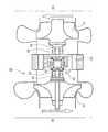
図1は、本発明の実施形態に係る過給装置を備える過給エンジンシステムの概略構成を示す図であり、図2は、本発明の実施形態に係る過給装置の概略構成を示す図である。本実施形態に係る過給エンジンシステムは、エンジン(内燃機関)53と、過給装置としてターボチャージャー(ターボ過給機)20と、を備える。本実施形態に係る過給エンジンシステムについては、例えば車両を駆動するための動力源として用いることができる。 FIG. 1 is a diagram showing a schematic configuration of a supercharged engine system including a supercharging device according to an embodiment of the present invention, and FIG. 2 is a diagram showing a schematic configuration of the supercharging device according to an embodiment of the present invention. is there. The supercharged engine system according to the present embodiment includes an engine (internal combustion engine) 53 and a turbocharger (turbosupercharger) 20 as a supercharging device. The supercharged engine system according to the present embodiment can be used as a power source for driving a vehicle, for example.
ターボチャージャー20は、タービン40及びコンプレッサ30を含んで構成される。タービン40は、例えば遠心タービンにより構成され、エンジン53からの排気のエネルギーを利用してタービンインペラ(タービン動翼)41を回転駆動する。コンプレッサ30は、例えば遠心圧縮機等のターボ圧縮機により構成され、コンプレッサインペラ(コンプレッサ動翼)31が回転駆動することで、コンプレッサ30上流の吸気通路からの吸気(エンジン53への吸気)を入口から吸入し、吸入した吸気を加圧して出口から吐出する。コンプレッサインペラ31の回転駆動によりコンプレッサ30で加圧された吸気は、コンプレッサ30下流の吸気通路を通り、エンジン53の吸気弁が開いているときに(吸気行程において)エンジン53の燃焼室内に導入される。エンジン53は、燃焼室内に導入された吸気を間欠的に燃焼させることで動力を発生する。その際には、燃料を吸気通路に噴射することも可能であるし、燃料を燃焼室内に直接噴射することも可能である。燃焼室内における燃焼後の排気は、エンジン53の排気弁が開いているときに(排気行程において)タービン40上流の排気通路へ排出され、さらに、タービンインペラ41を回転駆動するためにタービン40へ供給される。タービンインペラ41の回転駆動に利用された排気は、タービン40下流の排気通路へ排出される。 The
本実施形態では、タービンインペラ41とコンプレッサインペラ31が変速機構10を介して接続されており、タービンインペラ41から変速機構10を介してコンプレッサインペラ31へ回転が伝達される。ここでの変速機構10は、タービンインペラ41とコンプレッサインペラ31との回転速度比を連続的に変化させることが可能である。以下、変速機構10の構成例について説明する。 In the present embodiment, the
図1,2に示す例では、変速機構10は、第1及び第2回転要素としての一対のサイドギア11,12と、第3回転要素としての複数のピニオンギア13と、第4回転要素としての回転ケース14とを含む差動機構(差動歯車機構)により構成される。サイドギア12の回転中心軸はサイドギア11の回転中心軸と一致しており、回転ケース14の回転中心軸はサイドギア11,12の回転中心軸と一致しており、各ピニオンギア13の回転中心軸はサイドギア11,12及び回転ケース14の回転中心軸と直交している。各ピニオンギア13はサイドギア11,12と噛み合っており、各ピニオンギア13を介してサイドギア11,12間で回転が伝達される。その際には、サイドギア11,12同士でトルクの方向が互いに逆方向になるように、各ピニオンギア13でトルクの方向が反転してからサイドギア11,12間でトルクが伝達される。さらに、各ピニオンギア13は回転ケース14に回転自在に支持されており、回転ケース14の回転により各ピニオンギア13がサイドギア11の回転中心軸(サイドギア12及び回転ケース14の回転中心軸と一致する)まわりに周回(公転)する。各ピニオンギア13の周回により、サイドギア11,12と回転ケース14との間で回転が伝達される。その際には、サイドギア11とサイドギア12と回転ケース14とでトルクの方向が互いに同方向になるように、サイドギア11,12と回転ケース14との間でトルクが伝達される。 In the example shown in FIGS. 1 and 2, the
変速機構10においては、サイドギア11,12と回転ケース14のうちの1つがタービンインペラ41に接続され、サイドギア11,12と回転ケース14のうちの他の1つがコンプレッサインペラ31に接続され、サイドギア11,12と回転ケース14のうちの残りの1つが原動機としてのモータ50に接続される。このように、タービンインペラ41、コンプレッサインペラ31、及びモータ50は、変速機構10の異なる回転要素にそれぞれ接続される。図1,2に示す例では、サイドギア11がタービンシャフト42を介してタービンインペラ41に接続され、サイドギア12がコンプレッサシャフト32を介してコンプレッサインペラ31に接続され、回転ケース14がリングギア51及びピニオンギア52を介してモータ50に接続されている。タービンシャフト42(タービンインペラ41及びサイドギア11)は、軸受43を介して回転自在に支持されており、コンプレッサシャフト32(コンプレッサインペラ31及びサイドギア12)は、軸受33を介して回転自在に支持されている。モータ50は、例えば二次電池等の蓄電装置から供給された電力を利用して回転駆動可能である。さらに、モータ50は、発電運転を行うことも可能であり、発電運転による電力を蓄電装置に回収することも可能である。モータ50の回転駆動は制御装置により制御される。図2に示す例では、モータ50がターボチャージャー20本体外に配置されている。 In the
モータ50(回転ケース14)の回転が停止している状態では、図1の矢印に示すように、タービンインペラ41の回転は、サイドギア11から各ピニオンギア13を介してサイドギア12へ伝達されることで、コンプレッサインペラ31へ伝達される。その際には、コンプレッサインペラ31(サイドギア12)がタービンインペラ41(サイドギア11)と逆方向に回転し、コンプレッサインペラ31とタービンインペラ41とで回転速度の大きさ(絶対値)は等しくなる。 In a state where the rotation of the motor 50 (rotation case 14) is stopped, the rotation of the
一方、モータ50を回転駆動することで、モータ50の回転は、回転ケース14から各ピニオンギア13の公転によりサイドギア11,12へ伝達されることで、タービンインペラ41及びコンプレッサインペラ31へ伝達される。その際には、モータ50から回転ケース14に伝達されたトルクが、サイドギア11,12に分配(等分配)されてからタービンインペラ41及びコンプレッサインペラ31へ伝達される。さらに、コンプレッサインペラ31がタービンインペラ41と逆方向に回転している状態において、モータ50を回転駆動することで、モータ50(回転ケース14)の回転速度に応じて、タービンインペラ41の回転速度及びコンプレッサインペラ31の回転速度が連続的に変化し、タービンインペラ41の回転速度とコンプレッサインペラ31の回転速度との比が連続的に変化する。その場合において、回転ケース14をタービンインペラ41と同方向に回転させる(各ピニオンギア13をタービンインペラ41と同方向に周回させる)ようにモータ50を回転駆動するときは、図3の矢印に示すように、タービンインペラ41の回転速度が増加するとともにコンプレッサインペラ31の回転速度が減少し、タービンインペラ41とコンプレッサインペラ31との回転速度比の大きさ(絶対値)が増加する。一方、回転ケース14をタービンインペラ41と逆方向に回転させる(各ピニオンギア13をタービンインペラ41と逆方向に周回させる)ようにモータ50を回転駆動するときは、図4の矢印に示すように、タービンインペラ41の回転速度が減少するとともにコンプレッサインペラ31の回転速度が増加し、タービンインペラ41とコンプレッサインペラ31との回転速度比の大きさ(絶対値)が減少する。このように、変速機構10においては、モータ50の回転速度に応じて、タービンインペラ41とコンプレッサインペラ31との回転速度比を変化させることができ、タービンインペラ41とコンプレッサインペラ31の回転速度を任意に選択することができる。 On the other hand, by rotating the
タービン40の効率は、例えば図5に示すように、タービンインペラ41の回転速度とタービン40の膨張比に応じて変化し、タービンインペラ41の回転速度が低いときにタービン40の効率が低下しやすくなる。通常のターボチャージャーでは、タービンインペラとコンプレッサインペラが直結されており、タービンインペラとコンプレッサインペラとで回転速度が常に等しくなる。そのため、エンジン低回転域においては、タービンインペラ及びコンプレッサインペラともに回転速度が低くなり、タービンの効率が低下しやすくなる。一方、エンジン高回転域においては、タービンインペラ及びコンプレッサインペラともに回転速度が高くなり、タービンインペラの過回転やコンプレッサによる過給圧の過度な上昇を招きやすくなる。 For example, as shown in FIG. 5, the efficiency of the
これに対して本実施形態では、エンジン53の回転速度が低い場合は、回転ケース14をタービンインペラ41と同方向に回転させるようにモータ50を回転駆動することで、タービンインペラ41の回転駆動をモータ50のトルクによりアシストすることができ、コンプレッサインペラ31の回転速度に対してタービンインペラ41の回転速度を増加させることができる。これによって、タービン40の運転状態を例えば図5のAからBに移行させることができ、タービン40の効率を向上させることができる。したがって、エンジン53の加速時にコンプレッサ30による過給圧の上昇を速めることができるとともに、エンジン53の背圧を低減することができる。その結果、エンジン53の加速性能の向上、燃焼の改善、燃費向上の効果が得られる。さらに、エンジン53がガソリンエンジン等の火花点火機関である場合には、エンジン53の背圧を低減することによるノッキング抑制効果も期待できる。 On the other hand, in the present embodiment, when the rotational speed of the engine 53 is low, the rotation of the
一方、エンジン53の回転速度が高い場合は、タービンインペラ41の回転方向と逆方向のトルクを回転ケース14に作用させるようにモータ50にトルクを発生させて発電運転を行うことで、タービンインペラ41の余剰な動力(余剰な排気エネルギー)をモータ50の発電電力に変換して蓄電装置に回収することができ、タービンインペラ41の回転速度の上昇を抑えることができる。したがって、タービン40の効率が良好となるタービンインペラ41の回転速度を維持しながら、タービンインペラ41の過回転、及びコンプレッサ30による過給圧の過度な上昇を抑えることができる。 On the other hand, when the rotational speed of the engine 53 is high, the
以上説明したように、本実施形態によれば、モータ50の回転速度に応じてタービンインペラ41とコンプレッサインペラ31との回転速度比を任意に変化させることができるので、エンジン53の運転状態に応じてタービンインペラ41の回転速度を任意に選択することができる。その結果、エンジン53の運転状態が変化しても、タービン40の効率が良好となる運転条件でターボチャージャー20の運転が可能となる。 As described above, according to the present embodiment, the rotational speed ratio between the
また、特許文献1,2では、タービンインペラとコンプレッサインペラとを接続するシャフトに補助駆動用のモータを設けているため、モータは、常にタービンインペラ及びコンプレッサインペラと同じ回転速度で回転する。そのため、高速モータ及び高精度な制御系が必要となる。これに対して本実施形態では、コンプレッサインペラ31とタービンインペラ41が同じ回転速度で回転するときは、モータ50の回転は停止しており、タービンインペラ41とコンプレッサインペラ31との回転速度比を変化させる分だけモータ50を回転駆動すればよいため、モータ50の回転速度は、タービンインペラ41の回転速度及びコンプレッサインペラ31の回転速度よりも十分低くなる。そのため、安価な低速モータ及び制御系が使用可能となり、モータ50の効率も高くなる。また、本実施形態では、モータ50をターボチャージャー20本体外に配置することで、タービン40の高熱の影響を避けてモータ50の熱負荷を低減することができるとともに、モータ50の配置の自由度を高めることができる。 In Patent Documents 1 and 2, since an auxiliary drive motor is provided on a shaft connecting the turbine impeller and the compressor impeller, the motor always rotates at the same rotational speed as the turbine impeller and the compressor impeller. Therefore, a high speed motor and a highly accurate control system are required. In contrast, in the present embodiment, when the
本実施形態では、例えば図6に示すように、モータ50をターボチャージャー20本体に内蔵することも可能である。図6に示す例では、図2に示す例と比較して、リングギア51及びピニオンギア52が省略されており、変速機構10の回転ケース14がモータ50のロータに接続されている。ただし、モータ50をターボチャージャー20本体外に配置した方が、モータ50の配置の自由度を高める点では有利である。 In this embodiment, for example, as shown in FIG. 6, the
また、本実施形態では、サイドギア11,12とピニオンギア13の代わりに第1及び第2サイドローラとピニオンローラをそれぞれ設けることで、変速機構10がトラクションドライブ機構による差動機構であってもよい。 In the present embodiment, the
また、本実施形態において、タービンインペラ41とコンプレッサインペラ31とモータ50の、変速機構10の各回転要素への接続は、図1,2に示す例に限られるものではない。例えば、サイドギア11(あるいは第1サイドローラ)をモータ50に接続することも可能である。その場合は、サイドギア12(あるいは第2サイドローラ)をタービンインペラ41に接続し且つ回転ケース14をコンプレッサインペラ31に接続してもよいし、サイドギア12(あるいは第2サイドローラ)をコンプレッサインペラ31に接続し且つ回転ケース14をタービンインペラ41に接続してもよい。その場合においても、モータ50の回転速度に応じて、タービンインペラ41とコンプレッサインペラ31との回転速度比を連続的に変化させることが可能である。ただし、回転ケース14をモータ50に接続する構成の方が、モータ50の回転速度を低くする点では有利である。 Moreover, in this embodiment, the connection of the
また、本実施形態では、変速機構10が、第1及び第2回転要素としてのサンギア及びリングギアと、第3回転要素としてのピニオンギア(遊星ギア)と、第4回転要素としてのキャリアとを含む遊星歯車機構であってもよいし、第1及び第2回転要素としてのサンローラ及びリングローラと、第3回転要素としてのピニオンローラ(遊星ローラ)と、第4回転要素としてのキャリアとを含むトラクションドライブ機構による遊星ローラ機構であってもよい。その場合は、ピニオンギア(あるいはピニオンローラ)を介してサンギアとリングギアとの間(あるいはサンローラとリングローラとの間)で回転が伝達される。さらに、ピニオンギア(あるいはピニオンローラ)はキャリアに回転自在に支持されており、キャリアの回転によりピニオンギア(あるいはピニオンローラ)がサンギア(あるいはサンローラ)の回転中心軸まわりに周回(公転)する。 In the present embodiment, the
変速機構10がシングルピニオン遊星歯車機構(あるいはシングルピニオン遊星ローラ機構)である例においては、例えばサンギア(あるいはサンローラ)をタービンインペラ41に接続し、リングギア(あるいはリングローラ)をコンプレッサインペラ31に接続し、キャリアをモータ50に接続することで、モータ50の回転速度に応じて、タービンインペラ41とコンプレッサインペラ31との回転速度比を連続的に変化させることが可能である。その際には、モータ50からキャリアに伝達されたトルクが、サンギア及びリングギア(あるいはサンローラ及びリングローラ)に分配(等分配)されてからタービンインペラ41及びコンプレッサインペラ31へ伝達される。ただし、例えばサンギア(あるいはサンローラ)をモータ50に接続することも可能である。その場合は、リングギア(あるいはリングローラ)をタービンインペラ41に接続し且つキャリアをコンプレッサインペラ31に接続してもよいし、リングギア(あるいはリングローラ)をコンプレッサインペラ31に接続し且つキャリアをタービンインペラ41に接続してもよい。その場合においても、モータ50の回転速度に応じて、タービンインペラ41とコンプレッサインペラ31との回転速度比を連続的に変化させることが可能である。ただし、変速機構10がシングルピニオン遊星歯車機構(あるいはシングルピニオン遊星ローラ機構)である例においては、キャリアをモータ50に接続する構成の方が、モータ50の回転速度を低くする点では有利である。 In the example in which the
以上、本発明を実施するための形態について説明したが、本発明はこうした実施形態に何等限定されるものではなく、本発明の要旨を逸脱しない範囲内において、種々なる形態で実施し得ることは勿論である。 As mentioned above, although the form for implementing this invention was demonstrated, this invention is not limited to such embodiment at all, and it can implement with a various form in the range which does not deviate from the summary of this invention. Of course.
10 変速機構、11,12 サイドギア、13 ピニオンギア、14 回転ケース、20 ターボチャージャー、30 コンプレッサ、31 コンプレッサインペラ、32 コンプレッサシャフト、33,43 軸受、40 タービン、41 タービンインペラ、42 タービンシャフト、50 モータ、53 エンジン。 DESCRIPTION OF
Claims (4)
Translated fromJapaneseコンプレッサ動翼の回転によりエンジンへの吸気を加圧するコンプレッサと、
タービン動翼とコンプレッサ動翼との回転速度比を変化させる変速機構と、
を備え、
変速機構は、
第1及び第2回転要素と、
第1及び第2回転要素間で回転を伝達する第3回転要素と、
第3回転要素を回転自在に支持する第4回転要素であって、その回転により第3回転要素を第1回転要素の回転軸まわりに周回させる第4回転要素と、
を含み、
第1回転要素と第2回転要素と第4回転要素のうちの1つがタービン動翼に接続され、
第1回転要素と第2回転要素と第4回転要素のうちの他の1つがコンプレッサ動翼に接続され、
第1回転要素と第2回転要素と第4回転要素のうちの残りの1つが原動機に接続され、
原動機の回転速度に応じてタービン動翼とコンプレッサ動翼との回転速度比が変化する、過給装置。A turbine for rotating turbine blades using exhaust from the engine;
A compressor that pressurizes intake air into the engine by rotation of the compressor blades;
A speed change mechanism that changes a rotational speed ratio between the turbine blade and the compressor blade;
With
The transmission mechanism
First and second rotating elements;
A third rotating element that transmits rotation between the first and second rotating elements;
A fourth rotating element that rotatably supports the third rotating element, and rotates the third rotating element around the rotation axis of the first rotating element by the rotation;
Including
One of the first rotating element, the second rotating element and the fourth rotating element is connected to the turbine blade,
The other one of the first rotating element, the second rotating element and the fourth rotating element is connected to the compressor blade,
The remaining one of the first rotating element, the second rotating element and the fourth rotating element is connected to the prime mover;
A supercharging device in which a rotational speed ratio between a turbine blade and a compressor blade changes in accordance with the rotational speed of a prime mover.
第4回転要素が原動機に接続され、
原動機から第4回転要素に伝達されたトルクが第1及び第2回転要素に分配される、過給装置。The supercharging device according to claim 1,
The fourth rotating element is connected to the prime mover,
A supercharging device in which torque transmitted from a prime mover to a fourth rotating element is distributed to the first and second rotating elements.
変速機構は差動機構である、過給装置。The supercharging device according to claim 1 or 2,
A supercharging device in which the speed change mechanism is a differential mechanism.
コンプレッサ動翼の回転によりエンジンへの吸気を加圧するコンプレッサと、
を備え、
タービン動翼とコンプレッサ動翼との回転速度比を連続的に変化させることが可能な変速機構を介して、タービン動翼からコンプレッサ動翼へ回転が伝達される、過給装置。A turbine for rotating turbine blades using exhaust from the engine;
A compressor that pressurizes intake air into the engine by rotation of the compressor blades;
With
A turbocharger in which rotation is transmitted from a turbine blade to a compressor blade via a speed change mechanism capable of continuously changing a rotation speed ratio between the turbine blade and the compressor blade.
Priority Applications (1)
| Application Number | Priority Date | Filing Date | Title |
|---|---|---|---|
| JP2010016171AJP2011153583A (en) | 2010-01-28 | 2010-01-28 | Supercharger |
Applications Claiming Priority (1)
| Application Number | Priority Date | Filing Date | Title |
|---|---|---|---|
| JP2010016171AJP2011153583A (en) | 2010-01-28 | 2010-01-28 | Supercharger |
Publications (1)
| Publication Number | Publication Date |
|---|---|
| JP2011153583Atrue JP2011153583A (en) | 2011-08-11 |
Family
ID=44539723
Family Applications (1)
| Application Number | Title | Priority Date | Filing Date |
|---|---|---|---|
| JP2010016171APendingJP2011153583A (en) | 2010-01-28 | 2010-01-28 | Supercharger |
Country Status (1)
| Country | Link |
|---|---|
| JP (1) | JP2011153583A (en) |
Cited By (21)
| Publication number | Priority date | Publication date | Assignee | Title |
|---|---|---|---|---|
| CN103016140A (en)* | 2012-10-30 | 2013-04-03 | 长城汽车股份有限公司 | Split supercharger of turbo supercharged engine |
| WO2014124291A1 (en)* | 2013-02-08 | 2014-08-14 | Dana Limited | Internal combustion engine coupled turbocharger with an infinitely variable transmission |
| KR20150045925A (en)* | 2012-08-24 | 2015-04-29 | 사우디 아라비안 오일 컴퍼니 | A method of driving a CO2 compressor of a CO2 capture system using waste heat from an internal combustion engine |
| FR3013765A1 (en)* | 2013-11-28 | 2015-05-29 | Renault Sa | VARIABLE OPERATING TURBOCHARGER |
| US9347532B2 (en) | 2012-01-19 | 2016-05-24 | Dana Limited | Tilting ball variator continuously variable transmission torque vectoring device |
| US9353842B2 (en) | 2012-09-07 | 2016-05-31 | Dana Limited | Ball type CVT with powersplit paths |
| US9416858B2 (en) | 2012-09-07 | 2016-08-16 | Dana Limited | Ball type continuously variable transmission/infinitely variable transmission |
| US9541179B2 (en) | 2012-02-15 | 2017-01-10 | Dana Limited | Transmission and driveline having a tilting ball variator continuously variable transmission |
| US9551404B2 (en) | 2013-03-14 | 2017-01-24 | Dana Limited | Continuously variable transmission and an infinitely variable transmission variator drive |
| US9556943B2 (en) | 2012-09-07 | 2017-01-31 | Dana Limited | IVT based on a ball-type CVP including powersplit paths |
| US9556941B2 (en) | 2012-09-06 | 2017-01-31 | Dana Limited | Transmission having a continuously or infinitely variable variator drive |
| CN106438020A (en)* | 2016-10-20 | 2017-02-22 | 哈尔滨工程大学 | Electric auxiliary differential supercharger and control method thereof |
| US9599204B2 (en) | 2012-09-07 | 2017-03-21 | Dana Limited | Ball type CVT with output coupled powerpaths |
| US9638296B2 (en) | 2012-09-07 | 2017-05-02 | Dana Limited | Ball type CVT including a direct drive mode |
| US9638301B2 (en) | 2013-03-14 | 2017-05-02 | Dana Limited | Ball type continuously variable transmission |
| US9777815B2 (en) | 2013-06-06 | 2017-10-03 | Dana Limited | 3-mode front wheel drive and rear wheel drive continuously variable planetary transmission |
| US10030751B2 (en) | 2013-11-18 | 2018-07-24 | Dana Limited | Infinite variable transmission with planetary gear set |
| US10030748B2 (en) | 2012-11-17 | 2018-07-24 | Dana Limited | Continuously variable transmission |
| US10030594B2 (en) | 2015-09-18 | 2018-07-24 | Dana Limited | Abuse mode torque limiting control method for a ball-type continuously variable transmission |
| US10088022B2 (en) | 2013-11-18 | 2018-10-02 | Dana Limited | Torque peak detection and control mechanism for a CVP |
| CN110985196A (en)* | 2020-02-23 | 2020-04-10 | 郏政广 | An off-axis speed-increasing turbocharger |
- 2010
- 2010-01-28JPJP2010016171Apatent/JP2011153583A/enactivePending
Cited By (33)
| Publication number | Priority date | Publication date | Assignee | Title |
|---|---|---|---|---|
| US9347532B2 (en) | 2012-01-19 | 2016-05-24 | Dana Limited | Tilting ball variator continuously variable transmission torque vectoring device |
| US9541179B2 (en) | 2012-02-15 | 2017-01-10 | Dana Limited | Transmission and driveline having a tilting ball variator continuously variable transmission |
| KR101993947B1 (en) | 2012-08-24 | 2019-06-27 | 사우디 아라비안 오일 컴퍼니 | Method of driving a co₂compressor of a co₂capture system using waste heat from an internal combustion engine |
| KR20150045925A (en)* | 2012-08-24 | 2015-04-29 | 사우디 아라비안 오일 컴퍼니 | A method of driving a CO2 compressor of a CO2 capture system using waste heat from an internal combustion engine |
| JP2015513047A (en)* | 2012-08-24 | 2015-04-30 | サウジ アラビアン オイル カンパニー | Method for driving a CO2 compressor of a CO2 capture system using waste heat of an internal combustion engine |
| US9556941B2 (en) | 2012-09-06 | 2017-01-31 | Dana Limited | Transmission having a continuously or infinitely variable variator drive |
| US9556943B2 (en) | 2012-09-07 | 2017-01-31 | Dana Limited | IVT based on a ball-type CVP including powersplit paths |
| US9353842B2 (en) | 2012-09-07 | 2016-05-31 | Dana Limited | Ball type CVT with powersplit paths |
| US9416858B2 (en) | 2012-09-07 | 2016-08-16 | Dana Limited | Ball type continuously variable transmission/infinitely variable transmission |
| US10006527B2 (en) | 2012-09-07 | 2018-06-26 | Dana Limited | Ball type continuously variable transmission/infinitely variable transmission |
| US9638296B2 (en) | 2012-09-07 | 2017-05-02 | Dana Limited | Ball type CVT including a direct drive mode |
| US10088026B2 (en) | 2012-09-07 | 2018-10-02 | Dana Limited | Ball type CVT with output coupled powerpaths |
| US9689477B2 (en) | 2012-09-07 | 2017-06-27 | Dana Limited | Ball type continuously variable transmission/infinitely variable transmission |
| US9599204B2 (en) | 2012-09-07 | 2017-03-21 | Dana Limited | Ball type CVT with output coupled powerpaths |
| CN103016140A (en)* | 2012-10-30 | 2013-04-03 | 长城汽车股份有限公司 | Split supercharger of turbo supercharged engine |
| US10030748B2 (en) | 2012-11-17 | 2018-07-24 | Dana Limited | Continuously variable transmission |
| US9404414B2 (en) | 2013-02-08 | 2016-08-02 | Dana Limited | Internal combustion engine coupled turbocharger with an infinitely variable transmission |
| JP2018135887A (en)* | 2013-02-08 | 2018-08-30 | デーナ リミテッド | Internally connected engine turbocharger with continuously variable transmission |
| US9644530B2 (en) | 2013-02-08 | 2017-05-09 | Dana Limited | Internal combustion engine coupled turbocharger with an infinitely variable transmission |
| WO2014124291A1 (en)* | 2013-02-08 | 2014-08-14 | Dana Limited | Internal combustion engine coupled turbocharger with an infinitely variable transmission |
| EP3431734A1 (en)* | 2013-02-08 | 2019-01-23 | Dana Limited | Internal combustion engine coupled turbocharger with an infinitely variable transmission |
| JP2016507032A (en)* | 2013-02-08 | 2016-03-07 | デーナ リミテッド | Internally connected engine turbocharger with continuously variable transmission |
| US9689482B2 (en) | 2013-03-14 | 2017-06-27 | Dana Limited | Ball type continuously variable transmission |
| US9638301B2 (en) | 2013-03-14 | 2017-05-02 | Dana Limited | Ball type continuously variable transmission |
| US9933054B2 (en) | 2013-03-14 | 2018-04-03 | Dana Limited | Continuously variable transmission and an infinitely variable transmission variator drive |
| US9551404B2 (en) | 2013-03-14 | 2017-01-24 | Dana Limited | Continuously variable transmission and an infinitely variable transmission variator drive |
| US9777815B2 (en) | 2013-06-06 | 2017-10-03 | Dana Limited | 3-mode front wheel drive and rear wheel drive continuously variable planetary transmission |
| US10088022B2 (en) | 2013-11-18 | 2018-10-02 | Dana Limited | Torque peak detection and control mechanism for a CVP |
| US10030751B2 (en) | 2013-11-18 | 2018-07-24 | Dana Limited | Infinite variable transmission with planetary gear set |
| FR3013765A1 (en)* | 2013-11-28 | 2015-05-29 | Renault Sa | VARIABLE OPERATING TURBOCHARGER |
| US10030594B2 (en) | 2015-09-18 | 2018-07-24 | Dana Limited | Abuse mode torque limiting control method for a ball-type continuously variable transmission |
| CN106438020A (en)* | 2016-10-20 | 2017-02-22 | 哈尔滨工程大学 | Electric auxiliary differential supercharger and control method thereof |
| CN110985196A (en)* | 2020-02-23 | 2020-04-10 | 郏政广 | An off-axis speed-increasing turbocharger |
Similar Documents
| Publication | Publication Date | Title |
|---|---|---|
| JP2011153583A (en) | Supercharger | |
| CA2516273C (en) | Automotive air blowers | |
| EP2978949B1 (en) | Supercharging system and method for operating a supercharging system | |
| JP5035473B2 (en) | Turbocharger control device | |
| US8915082B2 (en) | Regenerative assisted turbocharger system | |
| JP2010534298A5 (en) | ||
| CN101198502A (en) | Vehicle propulsion system using motor/generator in transmission system to electrically drive electric supercharger | |
| JP2015150974A (en) | Control device for hybrid vehicle | |
| EP2573356B1 (en) | Supercharging system and method for operation | |
| JP5691402B2 (en) | Electric assist turbocharger | |
| CN101182805B (en) | Internal-combustion engines exhaust turbine dynamoelectric compressor system | |
| JP5552983B2 (en) | Electric turbo system | |
| US10788042B2 (en) | Traction drive fuel cell pump | |
| CN100395437C (en) | car blower | |
| JP2013238141A (en) | Supercharging device with electric motor of hybrid vehicle | |
| JP5691403B2 (en) | Electric assist turbocharger | |
| JP2017180159A (en) | Internal Combustion Engine System | |
| JP5501949B2 (en) | Power generation equipment | |
| JP6642190B2 (en) | Internal combustion engine system | |
| JP3249805U (en) | Regenerative power generation device | |
| JP2014139406A (en) | Surplus energy utilization device of supercharger | |
| JP2000204957A (en) | Internal combustion engine with supercharger | |
| JP6184741B2 (en) | Internal combustion engine | |
| JP2012092800A (en) | Electrically-assisted turbocharger | |
| JP2015120422A (en) | Control device of hybrid vehicle |