JP2011147413A - Plant factory - Google Patents
Plant factoryDownload PDFInfo
- Publication number
- JP2011147413A JP2011147413AJP2010012946AJP2010012946AJP2011147413AJP 2011147413 AJP2011147413 AJP 2011147413AJP 2010012946 AJP2010012946 AJP 2010012946AJP 2010012946 AJP2010012946 AJP 2010012946AJP 2011147413 AJP2011147413 AJP 2011147413A
- Authority
- JP
- Japan
- Prior art keywords
- sensor
- circuit
- plant factory
- cultivation room
- solar cell
- Prior art date
- Legal status (The legal status is an assumption and is not a legal conclusion. Google has not performed a legal analysis and makes no representation as to the accuracy of the status listed.)
- Withdrawn
Links
Images


Classifications
- Y—GENERAL TAGGING OF NEW TECHNOLOGICAL DEVELOPMENTS; GENERAL TAGGING OF CROSS-SECTIONAL TECHNOLOGIES SPANNING OVER SEVERAL SECTIONS OF THE IPC; TECHNICAL SUBJECTS COVERED BY FORMER USPC CROSS-REFERENCE ART COLLECTIONS [XRACs] AND DIGESTS
- Y02—TECHNOLOGIES OR APPLICATIONS FOR MITIGATION OR ADAPTATION AGAINST CLIMATE CHANGE
- Y02A—TECHNOLOGIES FOR ADAPTATION TO CLIMATE CHANGE
- Y02A40/00—Adaptation technologies in agriculture, forestry, livestock or agroalimentary production
- Y02A40/10—Adaptation technologies in agriculture, forestry, livestock or agroalimentary production in agriculture
- Y02A40/25—Greenhouse technology, e.g. cooling systems therefor
Landscapes
- Cultivation Of Plants (AREA)
- Greenhouses (AREA)
Abstract
Translated fromJapaneseDescription
Translated fromJapanese本発明は、閉鎖的な空間内で光強度、CO2濃度、温度、湿度などの生育環境を人工的に制御して作物を計画的に生産する植物工場に関する。 The present invention relates to a plant factory that artificially controls a growth environment such as light intensity, CO2 concentration, temperature, and humidity in a closed space to produce crops in a planned manner.
植物工場は、環境の調節が可能な閉鎖された空間において、光強度、温度、湿度、CO2濃度、照度、養液濃度、pHなど植物成長に影響を与える生育環境を人工的に制御することで、露地栽培に比べ天候不順などの自然環境や病虫害などに左右されることなく、高品質の無農薬野菜を一年中安定栽培し、安定価格で、安定供給できるメリットがある。特にLED照明の場合、光の波長(色)や照射方法(点滅照射など)を変えることで更なる作物の成長促進が可能になる。また、これまでの年1回の収穫に比べ、植物の成長能力を最大限に引き出すので、年数回の収穫が可能になり、さらに立体化・多段栽培化により単位面積当たりの栽培効率を大幅に向上させることができる。 In a closed space where the environment can be adjusted, the plant factory artificially controls the growth environment that affects plant growth, such as light intensity, temperature, humidity, CO2 concentration, illuminance, nutrient solution concentration, and pH. Compared to outdoor cultivation, there is an advantage that high quality pesticide-free vegetables can be cultivated stably throughout the year without being affected by the natural environment such as bad weather and pest damage. Especially in the case of LED lighting, further growth promotion of crops can be achieved by changing the wavelength (color) of light and the irradiation method (flashing irradiation, etc.). In addition, the plant's ability to grow is maximized compared to the previous annual harvesting, so it is possible to harvest several times a year, and further increase the cultivation efficiency per unit area through three-dimensional and multi-stage cultivation. Can be improved.
植物を効率よく良好に育成するためには光合成速度を最大限に高める必要がある。この光合成速度は光強度、CO2濃度、温度、湿度に依存するので、これらの状態を細かく見極め、それに応じて細かく制御する必要がある。そのため特許文献1では、図4に示すように、太陽電池などの光強度検知手段10、CO2センサ20、温度センサ30などを配置して出力を制御手段40へ送り、栽培室に設置したLEDなどの照明システム50、CO2を排出する改質器60、エアコンディショナなどの温度制御手段70を制御している。 In order to grow plants efficiently and satisfactorily, it is necessary to maximize the photosynthetic rate. Since this photosynthetic rate depends on light intensity, CO2 concentration, temperature, and humidity, it is necessary to determine these states in detail and to control them accordingly. Therefore, in
植物の生育環境を細かく制御するには多くのセンサを必要とし、そのため栽培室内に電源ケーブルや信号ケーブルなど多くの配線が必要になる。ところがセンサは植物の作付けや収穫時は作業の邪魔になるので一時的に取り除いたり、コストを抑えるため数を減らしたり、最適な測定場所を探して数を増やしたり場所を変えたりする。そのため多くの配線があるとこのような数の変更や移動が容易にできなくなる。また、配線が邪魔して光を遮ったり、多段栽培時に高さを取られないようにするときの障害になったり、CO2の拡散を防ぐ囲いやLED光の反射板などの設置が困難になる。また、配線が高温多湿な環境や酸性の養液に長時間さらされて腐食したり、水が配線を伝わって基板に滲み込んでショートしたり、誤動作する恐れもある。
何よりも栽培室内で配線が複雑に絡み合いながら露呈する様は美観上好ましくない。In order to finely control the plant growth environment, many sensors are required. For this reason, many wirings such as power cables and signal cables are required in the cultivation room. However, the sensor interferes with the work when planting or harvesting plants, so it is temporarily removed, the number is reduced to reduce costs, and the number is increased or changed in search of the optimal measurement location. Therefore, when there are many wirings, such a change and movement of the number cannot be easily performed. In addition, the wiring obstructs the light, obstructs the height not being taken up in multi-stage cultivation, and it becomes difficult to install an enclosure for preventing the diffusion of CO2 or a reflector for LED light. . In addition, the wiring may be corroded by being exposed to a hot and humid environment or an acidic nutrient solution for a long time, or water may penetrate the substrate through the wiring to cause a short circuit or malfunction.
Above all, it is not aesthetically pleasing that the wiring is exposed while being intertwined in the cultivation room.
解決しようとする問題点は以上のような点であり、本発明は、配線をコードレス化して栽培室内に設置するセンサを容易に移動・メンテナンスできる植物工場を提供することを目的になされたものである。 The problems to be solved are as described above, and the present invention was made for the purpose of providing a plant factory that can easily move and maintain a sensor that is cordless and installed in a cultivation room. is there.
そのため本発明は、栽培室内の状態を感知するセンサに、太陽電池パネルを取り付けて動作電源とする一方、RF回路を接続してセンサ出力を無線伝送し、これよりセンサに接続する電源ケーブルと信号ケーブルを不要にしたことを最も主要な特徴とする。 Therefore, the present invention attaches a solar cell panel to the sensor that senses the state of the cultivation room and uses it as an operating power supply, while connecting an RF circuit to wirelessly transmit the sensor output, and thereby connecting the power cable and signal to the sensor The main feature is that no cables are required.
本発明は、栽培室内の状態を感知するセンサに太陽電池パネルを取り付けて動作電源とし、RF回路を接続してセンサ出力を無線伝送するので、センサに接続する電源ケーブルや信号ケーブルなどの配線が不要になる。従って、センサの増減や移動が容易になり作業の都合やコストの低減に合わせて取り除いたり、設置場所を変更したりすることが自由にできるようになる。 In the present invention, a solar panel is attached to a sensor that senses the state in the cultivation room as an operation power supply, and an RF circuit is connected to wirelessly transmit the sensor output. Therefore, wiring such as a power cable and a signal cable connected to the sensor is not necessary. It becomes unnecessary. Therefore, the increase / decrease and movement of the sensor can be facilitated, and it can be freely removed or the installation location can be changed according to the convenience of work and cost reduction.
以下、本発明の実施の形態について説明する。 Embodiments of the present invention will be described below.
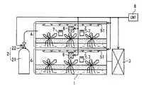
図1に、本発明を実施した植物工場の概略構成図を示す。
植物工場は、半閉鎖空間の栽培室1にCO2供給装置2と空調設備3を接続し、栽培室1内に既存の水耕栽培ユニット4を多段に設置する。
水耕栽培ユニット4は、各段にLEDモジュール5とファン6を取り付け、各段の適正箇所にCO2センサ、温度センサ、湿度センサなどの各種センサ7を配置する。水耕栽培ユニット4は、養液を循環させてLEDモジュール5の放射熱を吸収させる働きもある。
各種センサ7の測定データは制御ユニット8に伝送し、これら測定データの分析結果に基づいて制御ユニット8がCO2供給装置2、空調設備3、LEDモジュール5、ファン6を制御して栽培室1内のCO2濃度、光強度、温度、湿度などを調節する。In FIG. 1, the schematic block diagram of the plant factory which implemented this invention is shown.
The plant factory connects the
The
The measurement data of the
CO2供給装置2は、CO2ボンベ21に取り付けた電磁バルブ22を開閉してCO2の供給量を制御する。CO2は比重が空気の1.5倍あり、下に沈むので横から供給する。また、水に溶けると酸性化するのでその分炭酸塩などで養液を中和する必要がある。
CO2ボンベ21は、工場から排出されたCO2を充填することでCO2の工場排出量を削減し、CO2削減ビジネスの関連事業とすることができる。The
The
LEDモジュール5は、赤、緑、青の3色のLEDランプ51を複数配列して赤、緑、青の回路ブロックを形成し、回路ブロック毎にパルス幅のデュ−ティ・サイクルを変えるPWM制御して発光量や色相を制御する。
光合成には例えば350〜800nmの波長の光が有効で、波長を限定すればLEDの消費電力を低減できる。そのため植物の種類毎や生育状況に応じて適した波長(色)の光を選択できるよう、このように色の異なるLEDランプ51をいくつか組み合わせて配置する。The
For photosynthesis, for example, light having a wavelength of 350 to 800 nm is effective. If the wavelength is limited, the power consumption of the LED can be reduced. Therefore,
ファン6は、多段に設置した水耕栽培ユニット4の各段の空気を攪拌し、各段のCO2濃度、温度、湿度を平均化する。 The
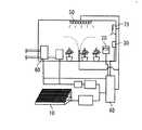
各種センサ7は、図2に示すように、太陽電池パネル9を動作電源とし、センサ回路71に送信側RF回路72を接続して測定データを制御ユニット8に無線伝送する。
太陽電池パネル9は、LEDランプ51の照射光を光電変換して電力を生成する。
制御ユニット8は、前段に受信側RF回路81を設置して各種センサ7の測定データを収集し、CO2供給装置2、空調設備3、LEDモジュール5、ファン6を制御する。As shown in FIG. 2, the
The
The
図3に、センサ回路のブロック図を示す。
センサ回路71は、センサ711の出力をアンプ712で増幅し、A/D変換器713でデジタル信号に変換してCPU714に入力する。
CPU714は、ROM715に格納されたプログラムを実行してデジタル信号の測定データを送信側RF回路72へ送出し、測定データをRAM716に記録する。FIG. 3 shows a block diagram of the sensor circuit.
The
The
センサ711は、CO2センサの場合、赤外線吸収式やガラス電極式に比べ小型で安価な固体電解質型センサを用いる。固体電解質型センサは、イオン導電性を有する固体電解質の両面に一対の電極を形成し、一方の電極がCO2と接触したときに2つの電極間で発生する導電イオンの濃度差に基づく起電力の変化を検出することによってCO2濃度を測定する。
温度センサや湿度センサの場合、出力を電気信号で取り出せ、センサ部を小型化できる抵抗変化型や静電容量変化型の電子式センサを用いる。In the case of a CO2 sensor, the
In the case of a temperature sensor or a humidity sensor, a resistance change type or capacitance change type electronic sensor that can take out an output with an electric signal and can downsize the sensor unit is used.
1 栽培室
2 CO2供給装置
21 CO2ボンベ
22 電磁バルブ
3 空調設備
4 水耕栽培ユニット
5 LEDモジュール
51 LEDランプ
6 ファン
7 各種センサ
71 センサ回路
711 センサ
712 アンプ
713 A/D変換器
714 CPU
715 ROM
716 RAM
72 送信側RF回路
8 制御ユニット
81 受信側RF回路
9 太陽電池パネル
10 光強度検知手段
20 CO2センサ
30 温度センサ
40 制御手段
50 照明システム
60 改質器
70 温度制御手段DESCRIPTION OF
715 ROM
716 RAM
72 Transmission-
Claims (3)
Translated fromJapanese太陽電池パネルを取り付けて動作電源とする一方、
RF回路を接続してセンサ出力を無線伝送し、
これよりセンサに接続する電源ケーブルと信号ケーブルを不要にしたことを特徴とする植物工場。To the sensor that senses the state in the cultivation room,
While installing a solar cell panel as an operating power source,
Connect the RF circuit to transmit the sensor output wirelessly,
A plant factory characterized by eliminating the need for power and signal cables to connect to the sensor.
このCO2ボンベのバルブを開閉して栽培室内のCO2濃度を調節することを特徴とする請求項1記載の植物工場。Connect a CO2 cylinder to the cultivation room,
2. The plant factory according to claim 1, wherein the CO2 concentration in the cultivation room is adjusted by opening and closing a valve of the CO2 cylinder.
Priority Applications (1)
| Application Number | Priority Date | Filing Date | Title |
|---|---|---|---|
| JP2010012946AJP2011147413A (en) | 2010-01-25 | 2010-01-25 | Plant factory |
Applications Claiming Priority (1)
| Application Number | Priority Date | Filing Date | Title |
|---|---|---|---|
| JP2010012946AJP2011147413A (en) | 2010-01-25 | 2010-01-25 | Plant factory |
Publications (1)
| Publication Number | Publication Date |
|---|---|
| JP2011147413Atrue JP2011147413A (en) | 2011-08-04 |
Family
ID=44535022
Family Applications (1)
| Application Number | Title | Priority Date | Filing Date |
|---|---|---|---|
| JP2010012946AWithdrawnJP2011147413A (en) | 2010-01-25 | 2010-01-25 | Plant factory |
Country Status (1)
| Country | Link |
|---|---|
| JP (1) | JP2011147413A (en) |
Cited By (12)
| Publication number | Priority date | Publication date | Assignee | Title |
|---|---|---|---|---|
| CN102287711A (en)* | 2011-08-10 | 2011-12-21 | 华南师范大学 | Full-automatic illumination device for plants |
| WO2013072990A1 (en)* | 2011-11-14 | 2013-05-23 | Mori Kazuo | Cultivation system and cultivation method |
| CN104035427A (en)* | 2014-06-30 | 2014-09-10 | 苏州大学 | Synchronized planting system for plant factories |
| CN104472247A (en)* | 2014-11-21 | 2015-04-01 | 无锡科思电子科技有限公司 | Plant growth dynamic light supplement system applied to greenhouse |
| JPWO2013072990A1 (en)* | 2011-11-14 | 2015-04-02 | 森 一生 | Cultivation system and cultivation method |
| JP2016002058A (en)* | 2014-06-19 | 2016-01-12 | 国立大学法人宇都宮大学 | Cultivation facility |
| KR101935591B1 (en)* | 2018-06-14 | 2019-01-04 | 주식회사 메이플테크 | Cultivation schale using IoT-based LED and sensor |
| WO2018203692A3 (en)* | 2017-05-04 | 2019-03-28 | 주식회사 메이플테크 | Culture vessel using iot-based led and sensor |
| KR102036006B1 (en)* | 2018-06-30 | 2019-10-24 | 주식회사 신성이엔지 | Energy Saving Heat Pump Thermohygrostat for Plant Factory and its Control Method |
| JP2020527358A (en)* | 2017-06-29 | 2020-09-10 | シーオー2アイ リミティド | Environmental control system |
| CN113924901A (en)* | 2021-06-07 | 2022-01-14 | 国家电投集团科学技术研究院有限公司 | DC power supply system for plant factory |
| US11994307B2 (en) | 2019-02-22 | 2024-05-28 | Mitsubishi Electric Corporation | Air conditioning system and management device |
- 2010
- 2010-01-25JPJP2010012946Apatent/JP2011147413A/ennot_activeWithdrawn
Cited By (12)
| Publication number | Priority date | Publication date | Assignee | Title |
|---|---|---|---|---|
| CN102287711A (en)* | 2011-08-10 | 2011-12-21 | 华南师范大学 | Full-automatic illumination device for plants |
| WO2013072990A1 (en)* | 2011-11-14 | 2013-05-23 | Mori Kazuo | Cultivation system and cultivation method |
| JPWO2013072990A1 (en)* | 2011-11-14 | 2015-04-02 | 森 一生 | Cultivation system and cultivation method |
| JP2016002058A (en)* | 2014-06-19 | 2016-01-12 | 国立大学法人宇都宮大学 | Cultivation facility |
| CN104035427A (en)* | 2014-06-30 | 2014-09-10 | 苏州大学 | Synchronized planting system for plant factories |
| CN104472247A (en)* | 2014-11-21 | 2015-04-01 | 无锡科思电子科技有限公司 | Plant growth dynamic light supplement system applied to greenhouse |
| WO2018203692A3 (en)* | 2017-05-04 | 2019-03-28 | 주식회사 메이플테크 | Culture vessel using iot-based led and sensor |
| JP2020527358A (en)* | 2017-06-29 | 2020-09-10 | シーオー2アイ リミティド | Environmental control system |
| KR101935591B1 (en)* | 2018-06-14 | 2019-01-04 | 주식회사 메이플테크 | Cultivation schale using IoT-based LED and sensor |
| KR102036006B1 (en)* | 2018-06-30 | 2019-10-24 | 주식회사 신성이엔지 | Energy Saving Heat Pump Thermohygrostat for Plant Factory and its Control Method |
| US11994307B2 (en) | 2019-02-22 | 2024-05-28 | Mitsubishi Electric Corporation | Air conditioning system and management device |
| CN113924901A (en)* | 2021-06-07 | 2022-01-14 | 国家电投集团科学技术研究院有限公司 | DC power supply system for plant factory |
Similar Documents
| Publication | Publication Date | Title |
|---|---|---|
| JP2011147413A (en) | Plant factory | |
| US11297772B2 (en) | LED grow light system | |
| KR101531759B1 (en) | Plant factory LED lighting system with controllable light source | |
| KR100883691B1 (en) | Plant growth apparatus and control system | |
| EP3003010B1 (en) | A system and method for providing illumination to plants | |
| CN103141344B (en) | The cold canopy of plastics green ring control apparatus and method | |
| KR101270383B1 (en) | Ubiquitous sensor network based plant factory led lighting system and method | |
| US20220046866A1 (en) | plant factory | |
| CN205375246U (en) | Warmhouse booth intelligence control system | |
| WO2014128746A1 (en) | Cultivation control system, cultivation control program, and cultivation control method | |
| KR20150033363A (en) | Plant factory LED lighting system with cooling and radiation structure | |
| KR101451701B1 (en) | Plant cultivation system for use in combination with light and artificial light | |
| CN104714506A (en) | Intelligent vegetable greenhouse management system | |
| KR101102279B1 (en) | LED Plant Growth System Using Ambient Light | |
| CN103314834A (en) | Green household plant conservation control device based on ARM processor | |
| CN103535218A (en) | Solar photovoltaic power generation based automatic light supplementing and watering system of greenhouse | |
| TWM536840U (en) | Indoor planting system | |
| KR101368781B1 (en) | System for lightning environment of greenhouse | |
| CN211236713U (en) | Greenhouse remote control system based on Internet of things | |
| Piromalis et al. | Smart precision lighting for urban and landscape closed controlled horticultural environments | |
| CN106132012B (en) | A method for large-scale intelligent cultivation of plants | |
| CN109471475A (en) | A kind of green house of vegetables monitoring management system | |
| CN108319313A (en) | A kind of photovoltaic green-house intelligence control system | |
| KR20200013151A (en) | Big-data based smart controlling method for enhancing graft-take and the plant factory system | |
| CN210017065U (en) | Greenhouse environment illumination intelligent control system |
Legal Events
| Date | Code | Title | Description |
|---|---|---|---|
| A300 | Withdrawal of application because of no request for examination | Free format text:JAPANESE INTERMEDIATE CODE: A300 Effective date:20130402 |