JP2011145928A - Power source control system - Google Patents
Power source control systemDownload PDFInfo
- Publication number
- JP2011145928A JP2011145928AJP2010006845AJP2010006845AJP2011145928AJP 2011145928 AJP2011145928 AJP 2011145928AJP 2010006845 AJP2010006845 AJP 2010006845AJP 2010006845 AJP2010006845 AJP 2010006845AJP 2011145928 AJP2011145928 AJP 2011145928A
- Authority
- JP
- Japan
- Prior art keywords
- power supply
- supply unit
- voltage
- output
- constant current
- Prior art date
- Legal status (The legal status is an assumption and is not a legal conclusion. Google has not performed a legal analysis and makes no representation as to the accuracy of the status listed.)
- Pending
Links
Images

Landscapes
- Circuit Arrangement For Electric Light Sources In General (AREA)
- Continuous-Control Power Sources That Use Transistors (AREA)
Abstract
Translated fromJapaneseDescription
Translated fromJapanese本発明は、電源ユニットとそのDC電源の供給を受けて動作する負荷装置を配線で接続して電源入出力を制御する電源制御システムに関する。 The present invention relates to a power supply control system for controlling power supply input / output by connecting a power supply unit and a load device that operates by receiving the DC power supply by wiring.
従来、電源ユニットとそのDC電源の供給を受けて動作する負荷装置を配線で接続する電源入出力システムに関して、電源ユニットは負荷装置に対して、出力電圧については、予め負荷装置が必要とする最小電圧を調査の上、その最小電圧以上になるように手動で出力電圧を設定することが多かった。 Conventionally, regarding a power input / output system in which a power supply unit and a load device that operates by receiving the DC power supply are connected by wiring, the power supply unit has a minimum output voltage required for the load device in advance. In many cases, after investigating the voltage, the output voltage was manually set to be equal to or higher than the minimum voltage.
一方、出力電圧を自動で設定する例としては、液晶表示装置の面光源電源制御回路がある(特許文献1参照)。面光源電源制御回路は、電源出力電圧より参照電圧を検出し、その参照電圧が必要な最小限の駆動電位以上となるように電源出力電圧を自動制御するものである。こうした電源出力電圧の自動制御は、出力電圧の手動設定を不要化し、また、効率的な電圧値に自動設定することにより消費電力の低減を図るものである。 On the other hand, as an example of automatically setting the output voltage, there is a surface light source power supply control circuit of a liquid crystal display device (see Patent Document 1). The surface light source power supply control circuit detects a reference voltage from the power supply output voltage, and automatically controls the power supply output voltage so that the reference voltage becomes equal to or higher than a necessary minimum driving potential. Such automatic control of the power supply output voltage eliminates the need for manual setting of the output voltage and reduces power consumption by automatically setting the voltage to an efficient voltage value.
電源ユニットとそのDC電源の供給を受けて動作する負荷装置を配線で接続する電源入出力システムに関して、電源ユニットは接続する負荷装置への配線長によって必要な最小出力電圧が異なる。そのため、電源ユニットの出力電圧は予め余裕をもった配線長に対応した電圧となるように設定する必要があり、無駄な消費電力の発生があった。特許文献1に開示されている回路は、内部回路で参照電圧を検出してその結果をフィードバックし、出力電圧を適切な値に自動設定することにより無駄な電力消費を低減するものである。 Regarding a power input / output system in which a power supply unit and a load device that operates by receiving the supply of DC power are connected by wiring, the power supply unit has a different minimum output voltage depending on the wiring length to the load device to be connected. Therefore, the output voltage of the power supply unit needs to be set in advance so as to be a voltage corresponding to the wiring length having a margin, and wasteful power consumption occurs. The circuit disclosed in
また、本出願人は、単一又は複数のLEDが直列に接続されたLED群に電力を供給するLEDドライバであって、LED群に直列に定電流回路部を接続して自己に流れる電流を所定値に調整して維持し、定電流回路部に直列に、スイッチングレギュレータによって電圧を調整する電圧調整部を接続して、定電流回路部が負担する電圧降下がより適正状態となるように電圧調整をすることで、定電流回路部の負担を軽減させることを提案している(特許文献2)。 In addition, the present applicant is an LED driver that supplies power to an LED group in which a single or a plurality of LEDs are connected in series, and a constant current circuit unit is connected in series to the LED group to generate a current flowing through the LED driver. A voltage adjustment unit that adjusts and maintains the voltage to a predetermined value and is connected in series with the constant current circuit unit by a switching regulator so that the voltage drop borne by the constant current circuit unit is more appropriate. It has been proposed to reduce the burden on the constant current circuit section by adjusting (Patent Document 2).
ところで、電源ユニットと負荷装置の間には配線長に応じた電圧降下(以下、「配線長ドロップ」と記す)があり、配線長ドロップとしては電源側配線とGND(接地)側配線による電位降下が発生するため、上記特許文献1に記載の参照電圧検出方法では対応できない。その理由は、配線ドロップが電源側のみに存在していてGND側では電源ユニットと負荷装置とで共通電位であれば、特許文献1における電圧検出方法で対応できるが、GND側にも配線ドロップが発生する場合には、電源ユニットと負荷装置とがGND側で共通電位でなくなるため、対応できなくなるからである。 Incidentally, there is a voltage drop (hereinafter referred to as “wiring length drop”) between the power supply unit and the load device, and the potential drop due to the power supply side wiring and the GND (grounding) side wiring as the wiring length drop. Therefore, the reference voltage detection method described in
そこで、電源ユニットとそのDC電源の供給を受けて動作する負荷装置を配線で接続する電源入出力システムにおいて、負荷装置側を定電流駆動しようとする際に必要な定電流値が得られない場合には、そうした事態に自動的に対応して、負荷装置に対して必要最小限の出力電圧を電源ユニットより供給することを可能にする点で解決すべき課題がある。 この発明の目的は、負荷装置側を定電流駆動しようとする際に、無駄な電力消費を極力抑えることを可能にする電源制御システムを提供することである。 Therefore, in a power supply input / output system in which a power supply unit and a load device that operates by receiving the DC power supply are connected by wiring, a constant current value necessary for constant current drive on the load device side cannot be obtained. However, there is a problem to be solved in that it is possible to automatically respond to such a situation and to supply the minimum necessary output voltage to the load device from the power supply unit. An object of the present invention is to provide a power supply control system that can suppress wasteful power consumption as much as possible when the load device side is driven at a constant current.
上記課題に対する解決策として、この発明による電源制御システムは、電源ユニットとそのDC電源の供給を受けて動作する負荷装置を複数の配線で接続する電源入出力システムにおいて、前記負荷装置側は定電流駆動され、必要な定電流値が得られるか否かで電源供給状態の良否を判定し、その判定結果に基づいてDC電源供給ラインの配線による電圧降下を補償した上で、前記負荷装置に対して必要最小限の電圧を前記電源ユニットより供給することを特徴としている。 As a solution to the above problem, a power control system according to the present invention is a power input / output system in which a power supply unit and a load device that operates by receiving the supply of DC power are connected by a plurality of wirings. Whether the power supply state is good or not is determined based on whether or not a required constant current value is obtained, and based on the determination result, a voltage drop due to the wiring of the DC power supply line is compensated for the load device. The minimum necessary voltage is supplied from the power supply unit.
負荷装置側が定電流駆動され、負荷装置側で必要な定電流値が得られるかどうかを見て、必要な定電流値が得られない場合は、電源ユニット側の出力電圧を上げるようにフィードバック制御する。初めは電源ユニットの出力電圧を低めにしておいて、負荷装置側で必要な定電流値が得られるようになるまで、徐々に電源ユニットの出力電圧を上げてゆく。このようにして電源ユニットの出力電圧を設定するようにすれば、必要以上に無駄な消費電力を低減することができる。1 台の電源ユニットに対して複数の負荷装置が接続されている場合は、全ての負荷装置で必要な定電流値が確保されるまで、電源ユニットの出力電圧を上げてゆく。 Feedback control to increase the output voltage on the power supply unit side when the load device side is driven with constant current and the required constant current value is not obtained on the load device side. To do. Initially, the output voltage of the power supply unit is lowered, and the output voltage of the power supply unit is gradually increased until the required constant current value is obtained on the load device side. By setting the output voltage of the power supply unit in this way, it is possible to reduce unnecessary power consumption more than necessary. When multiple load devices are connected to one power supply unit, increase the output voltage of the power supply unit until the necessary constant current value is secured in all load devices.
このような制御を行うためには、電源ユニットと負荷装置の間で制御信号の送受信が必要になる。電源ライン(プラス側とマイナス側)以外に専用の制御ラインを設けてもよいが、制御信号の送受信を電源ラインに重畳すれば、電源ユニットと負荷装置間の配線数を削減でき(複数の負荷装置が接続されている場合でも、電源ユニットと全ての負荷装置の電源ライン(プラス側)を共通に接続し、かつそれらの電源ライン(マイナス側)を共通に接続するような送り配線をすれば(後述の実施例参照)配線は2 本のみで済む)、配線工事が簡便となる。また、前記DC電源の入出力ラインをハイ・インピーダンスに構成することができる。 In order to perform such control, it is necessary to transmit and receive control signals between the power supply unit and the load device. A dedicated control line may be provided in addition to the power supply line (positive side and negative side), but if transmission and reception of control signals are superimposed on the power supply line, the number of wires between the power supply unit and the load device can be reduced (multiple loads Even if the device is connected, if the power supply unit and the power supply line (positive side) of all load devices are connected in common, and the power supply line (minus side) is connected in common (Refer to the examples described later.) Only two wires are required.) Wiring work is simplified. Further, the input / output line of the DC power source can be configured to have a high impedance.
この発明に係る電源制御システムによれば、電源ユニットとそのDC電源の供給を受けて動作する負荷装置を配線で接続する電源入出力システムに関して、接続する各負荷装置への配線長が異なっても電源ユニットからはシステムとして必要な最小限の電圧を出力するようにして、無駄な消費電力の発生を低減することができる。また、負荷装置側で必要な定電流値が得られないことに応じて当該定電流値が得られるまで電源ユニット側の出力電圧を上昇させるフィードバック制御を行うので、必要以上に無駄な消費電力を低減することができる。更に、こうした電源制御のためには、電源ユニットと負荷装置の間で制御信号の送受信をする必要が生じるが、制御信号の送受信を電源ラインに重畳することで配線数を削減し、配線工事を簡便にすることができる。 According to the power supply control system of the present invention, regarding a power supply input / output system that connects a power supply unit and a load device that operates by receiving supply of DC power by wiring, even if the wiring length to each connected load device is different. By generating the minimum voltage necessary for the system from the power supply unit, it is possible to reduce generation of useless power consumption. In addition, feedback control is performed to increase the output voltage on the power supply unit side until the constant current value is obtained when the required constant current value is not obtained on the load device side. Can be reduced. Furthermore, for such power control, it is necessary to transmit and receive control signals between the power supply unit and the load device. However, by superimposing transmission and reception of control signals on the power supply line, the number of wires can be reduced, and wiring work can be performed. It can be simplified.
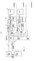
以下、本考案における実施例を図面の記載に基づいて説明する。図1は本実施例に基づく電源ユニットの接続構成及び電源ユニット内部の回路構成のブロック図である。本実施例では1 台の電源ユニットに対してLED照明装置1、LED照明装置2、LED照明装置3(LED照明装置1、2と同様の構造であるので詳細を省略)・・の複数の負荷装置が接続されている。電源ユニットは定電圧回路1、制御回路部2、コマンド信号送受信回路部4を備えて構成されている。 Embodiments of the present invention will be described below based on the drawings. FIG. 1 is a block diagram of a connection configuration of a power supply unit and a circuit configuration inside the power supply unit according to this embodiment. In this embodiment, a plurality of loads of
各LED照明装置は、定電流回路12、コマンド信号送受信回路部13、制御回路部17、LED部18、及びトランジスタTR2で構成されている。定電流回路12は、トランジスタTR1、抵抗14及び19、ダイオード15及び20から構成される。TR2は、制御回路部17からのパルス駆動出力を受けて、定電流回路12からの出力を短時間にON/OFFする。TR2の出力ON時にはLED部18に電源供給をONし、LED部18のLEDを点灯させる。TR2の出力OFF時にはLED部18に電源供給をOFFし、LED部18のLEDを消灯させる。この短時間でのON時間とOFF時間の割合を変更するLEDの点灯/消灯動作により、LEDの明るさを所望の明るさに制御する、即ち調光することが可能となる。 Each LED illumination device includes a constant
電源ユニットとLED照明装置との間は、配線抵抗で接続される。配線抵抗5と配線抵抗6 はLED照明装置1への配線抵抗であり、配線抵抗5は電源ユニットの電源側とLED照明装置1の電源側との間の配線抵抗であり、配線抵抗6は電源ユニットのGND側とLED照明装置1のGND側との間の配線抵抗である。配線抵抗7,8、9,10も同様に、LED照明装置2及びLED照明装置3への配線抵抗である。すなわち、配線抵抗7は、LED照明装置1の電源側とLED照明装置2の電源側との間の配線抵抗であり、配線抵抗9は、LED照明装置2の電源側とLED照明装置3の電源側との間の配線抵抗である。また、配線抵抗8は、LED照明装置1のGND側とLED照明装置2のGND側との間の配線抵抗であり、配線抵抗9は、LED照明装置2のGND側とLED照明装置3のGND側との間の配線抵抗である。 The power supply unit and the LED lighting device are connected by a wiring resistance. The wiring resistance 5 and the wiring resistance 6 are wiring resistances to the
図2は、LED部18の詳細を示す回路図である。LED1〜LED160は照明用LEDであり、抵抗R1〜R20はLEDの電流制限抵抗である。 FIG. 2 is a circuit diagram showing details of the
電源ユニット内のコマンド信号送受信回路部4とLED照明装置内のコマンド信号送受信回路部13との間でコマンド信号の送受信を行い、その結果に基づき、電源ユニット内の制御回路部2は定電圧回路1の定電圧出力値を設定する。電源入出力ラインに重畳するコマンド信号は高周波信号(例えば1MHzFSK信号)であり、電源回路の低インピーダンス性によってその信号レベルが小さくならないように、コイル3、コイル11によってコマンド信号に対するインピーダンスを高くしている。定電圧回路1の定電圧値はLED照明装置1,2…に必要な定電流値が確保できる最小値が設定され、不必要に高い電圧値を出力して無駄な消費電力を発生させないように制御される。 Command signal transmission / reception is performed between the command signal transmission /
LED照明装置に必要な定電流値を確保するための最小の定電圧値(電源ユニット内の定電圧回路1の出力)は、次のように設定される。即ち、抵抗14における電圧ドロップがダイオード15における電圧ドロップ(≒0.6V;流れる電流が大きくなると電圧降下も大きくなるが、0.6Vまで上昇すると電流が増加しても略一定)と略等しくなるようTR1に定電流が流れる時のTR1の最小コレクタ−エミッタ間電圧(上記の電圧ドロップの関係が成立した後は、電源ユニットの出力電圧を上げても定電流値は変わらずTR1のコレクタ−エミッタ間電圧が上昇する)に、コイル3及び11、電源側配線抵抗5、GND側配線抵抗6、抵抗14、TR2、LED部18を直列に流れる定電流によって生ずる各電圧値を合計した値に上記の最小の定電圧値は定まる。 The minimum constant voltage value (the output of the
電源ユニットとLED照明装置の接続当初においては、定電圧出力は、やや低めに設定されており、必要な定電流値が確保できるまで、コマンド信号の送受信により徐々に上昇させる。LED照明装置内の制御回路部17は、抵抗14における電圧ドロップとダイオード15における電圧ドロップの差がある規定範囲内に入るまで、電源ユニット内の定電圧回路1の定電圧出力を上昇させるように、コマンド信号の送受信を行うようコマンド信号送受信回路部13に指示する。 At the beginning of the connection between the power supply unit and the LED lighting device, the constant voltage output is set slightly lower, and is gradually increased by transmission / reception of a command signal until a necessary constant current value can be secured. The control circuit unit 17 in the LED lighting device increases the constant voltage output of the
即ち、制御回路部17への電流値検出入力において、抵抗14に流れる電流による電圧ドロップがダイオード15における電圧ドロップ(≒0.6V)より小さい場合は、制御回路部17はコマンド送受信回路部13を制御し、コマンド送受信回路部13から電源ユニット側のコマンド送受信回路4に対し、定電圧回路1の出力を上昇させるためのコマンド信号を送信する。定電圧回路1の出力を上昇させても、抵抗14に流れる電流による電圧ドロップがダイオード15における電圧ドロップ(≒0.6V)より小さい場合は、更に定電圧回路1の出力を上昇させるためのコマンドを送信する。このコマンド送信と定電圧回路1の出力上昇を抵抗14に流れる電流による電圧ドロップがダイオード15における電圧ドロップ(≒0.6V )と略等しくなるまで繰り返す。 That is, in the current value detection input to the control circuit unit 17, when the voltage drop due to the current flowing through the
このようにすれば、電源ユニットとLED照明装置間には配線抵抗5,6があるが、配線抵抗による電圧降下を加味した上で、最小の電源ユニットの定電圧出力が設定されることになる。また、電源ユニット1台に対して、複数のLED照明装置が接続される場合でも、配線抵抗の最も高い箇所の電圧降下を加味した上で、最小の電源ユニットの定電圧出力を設定することになる。即ち、LED照明装置1に対して配線抵抗5,6があり、LED照明装置2に対して配線抵抗5,6に加えて配線抵抗7,8があり、LED照明装置2への総合配線抵抗の方が高いので、LED照明装置2への配線抵抗5,6に加えて配線抵抗7,8での電圧降下を加味して、電源ユニットの定電圧回路1の出力が設定され、LED照明装置2に対して必要最小限の電圧が入力されることになる。この場合、LED照明装置1に対しては高めの電圧が入力されるが、その余分の消費電力は定電流回路12で消費される。 In this way, there are wiring resistances 5 and 6 between the power supply unit and the LED lighting device, but the minimum constant voltage output of the power supply unit is set in consideration of the voltage drop due to the wiring resistance. . In addition, even when a plurality of LED lighting devices are connected to one power supply unit, the constant voltage output of the minimum power supply unit is set after taking into account the voltage drop at the location with the highest wiring resistance. Become. That is, there are wiring resistances 5 and 6 for the
上記の説明において、LED部18は一般的な負荷回路部に置き換えてもよい。それにしたがって、LED照明装置は、一般的な負荷装置に置き換えることもできる。 In the above description, the
1 定電圧回路 2 制御回路部
3 コイル 4 コマンド送受信回路部
5,6,7,8,9,10 配線抵抗
11 コイル 12 定電流回路
13 コマンド送受信回路部 14 抵抗
15,20 ダイオード
18 LED部 19 抵抗
TR1;TR2 トランジスタDESCRIPTION OF
Claims (5)
Translated fromJapanesePriority Applications (1)
| Application Number | Priority Date | Filing Date | Title |
|---|---|---|---|
| JP2010006845AJP2011145928A (en) | 2010-01-15 | 2010-01-15 | Power source control system |
Applications Claiming Priority (1)
| Application Number | Priority Date | Filing Date | Title |
|---|---|---|---|
| JP2010006845AJP2011145928A (en) | 2010-01-15 | 2010-01-15 | Power source control system |
Publications (1)
| Publication Number | Publication Date |
|---|---|
| JP2011145928Atrue JP2011145928A (en) | 2011-07-28 |
Family
ID=44460718
Family Applications (1)
| Application Number | Title | Priority Date | Filing Date |
|---|---|---|---|
| JP2010006845APendingJP2011145928A (en) | 2010-01-15 | 2010-01-15 | Power source control system |
Country Status (1)
| Country | Link |
|---|---|
| JP (1) | JP2011145928A (en) |
Cited By (5)
| Publication number | Priority date | Publication date | Assignee | Title |
|---|---|---|---|---|
| CN102612225A (en)* | 2012-03-06 | 2012-07-25 | 广州金升阳科技有限公司 | Power circuit capable of being used for LED drive |
| JP2013120722A (en)* | 2011-12-08 | 2013-06-17 | Mitsubishi Electric Corp | Light source lighting device and lighting fixture |
| CN104850162A (en)* | 2015-03-18 | 2015-08-19 | 北京航天自动控制研究所 | High-reliability constant current source circuit with instant high voltage connection restraining function |
| JP2017157402A (en)* | 2016-03-01 | 2017-09-07 | 東芝ライテック株式会社 | Lighting device and lighting system |
| JP2023502350A (en)* | 2019-11-12 | 2023-01-24 | シグニファイ ホールディング ビー ヴィ | Light-emitting diode (LED)-based lighting device configured to emit light of a specific color, and corresponding method |
Citations (25)
| Publication number | Priority date | Publication date | Assignee | Title |
|---|---|---|---|---|
| JPH04287598A (en)* | 1991-03-18 | 1992-10-13 | Toshiba Corp | Communication method between power supply and load |
| JPH07332746A (en)* | 1994-06-13 | 1995-12-22 | Hitachi Ltd | Controller for air conditioner |
| JP2001215913A (en)* | 2000-02-04 | 2001-08-10 | Toko Inc | Lighting circuit |
| JP2003068480A (en)* | 2001-08-24 | 2003-03-07 | Toko Inc | Dimming control circuit |
| JP2004134147A (en)* | 2002-10-08 | 2004-04-30 | Koito Mfg Co Ltd | Lighting circuit |
| JP2005318789A (en)* | 2004-03-30 | 2005-11-10 | Rohm Co Ltd | Voltage controller, electronic apparatus using the same and voltage control method |
| JP2005537669A (en)* | 2002-08-27 | 2005-12-08 | フェアーチャイルド セミコンダクター コーポレイション | High efficiency LED driver |
| JP2006005535A (en)* | 2004-06-16 | 2006-01-05 | Yaskawa Electric Corp | Power line communication system |
| JP2006062591A (en)* | 2004-08-30 | 2006-03-09 | Yazaki Corp | Car exterior lamp control system |
| JP2006185942A (en)* | 2004-12-24 | 2006-07-13 | Toshiba Matsushita Display Technology Co Ltd | Surface light source controller |
| JP2006234970A (en)* | 2005-02-22 | 2006-09-07 | Canon Inc | Image forming apparatus, control method therefor, and control program |
| JP2006262593A (en)* | 2005-03-16 | 2006-09-28 | Matsushita Electric Works Ltd | Feed controller, feeder, and feeder system |
| JP2006278304A (en)* | 2005-03-25 | 2006-10-12 | Sanee Denki Kk | LED lighting device |
| JP2007110070A (en)* | 2005-10-11 | 2007-04-26 | O2 Micro Inc | Controller circuit for light emitting diode |
| JP2007220855A (en)* | 2006-02-16 | 2007-08-30 | Matsushita Electric Ind Co Ltd | LED lighting circuit |
| JP2007236095A (en)* | 2006-02-28 | 2007-09-13 | Ccs Inc | LED power supply device and light irradiation device |
| JP2008077892A (en)* | 2006-09-19 | 2008-04-03 | Alpine Electronics Inc | LED drive control device |
| JP2008134288A (en)* | 2006-11-27 | 2008-06-12 | Sharp Corp | LED driver |
| JP2009012669A (en)* | 2007-07-06 | 2009-01-22 | Koito Mfg Co Ltd | Lighting control device for vehicular light |
| JP2009021175A (en)* | 2007-07-13 | 2009-01-29 | Toshiba Lighting & Technology Corp | Lighting device |
| JP2009099894A (en)* | 2007-10-19 | 2009-05-07 | Toko Inc | LED lighting control device |
| JP2009520331A (en)* | 2005-12-20 | 2009-05-21 | ティーアイアール テクノロジー エルピー | Method and apparatus for controlling the current supplied to an electronic device |
| JP2009134933A (en)* | 2007-11-29 | 2009-06-18 | Mitsubishi Electric Corp | LED lighting device and vehicle headlamp |
| JP2009296883A (en)* | 2009-09-18 | 2009-12-17 | Sony Corp | Device and method for power supply |
| JP2010011608A (en)* | 2008-06-26 | 2010-01-14 | Mitsumi Electric Co Ltd | Semiconductor integrated circuit for power supply control |
- 2010
- 2010-01-15JPJP2010006845Apatent/JP2011145928A/enactivePending
Patent Citations (25)
| Publication number | Priority date | Publication date | Assignee | Title |
|---|---|---|---|---|
| JPH04287598A (en)* | 1991-03-18 | 1992-10-13 | Toshiba Corp | Communication method between power supply and load |
| JPH07332746A (en)* | 1994-06-13 | 1995-12-22 | Hitachi Ltd | Controller for air conditioner |
| JP2001215913A (en)* | 2000-02-04 | 2001-08-10 | Toko Inc | Lighting circuit |
| JP2003068480A (en)* | 2001-08-24 | 2003-03-07 | Toko Inc | Dimming control circuit |
| JP2005537669A (en)* | 2002-08-27 | 2005-12-08 | フェアーチャイルド セミコンダクター コーポレイション | High efficiency LED driver |
| JP2004134147A (en)* | 2002-10-08 | 2004-04-30 | Koito Mfg Co Ltd | Lighting circuit |
| JP2005318789A (en)* | 2004-03-30 | 2005-11-10 | Rohm Co Ltd | Voltage controller, electronic apparatus using the same and voltage control method |
| JP2006005535A (en)* | 2004-06-16 | 2006-01-05 | Yaskawa Electric Corp | Power line communication system |
| JP2006062591A (en)* | 2004-08-30 | 2006-03-09 | Yazaki Corp | Car exterior lamp control system |
| JP2006185942A (en)* | 2004-12-24 | 2006-07-13 | Toshiba Matsushita Display Technology Co Ltd | Surface light source controller |
| JP2006234970A (en)* | 2005-02-22 | 2006-09-07 | Canon Inc | Image forming apparatus, control method therefor, and control program |
| JP2006262593A (en)* | 2005-03-16 | 2006-09-28 | Matsushita Electric Works Ltd | Feed controller, feeder, and feeder system |
| JP2006278304A (en)* | 2005-03-25 | 2006-10-12 | Sanee Denki Kk | LED lighting device |
| JP2007110070A (en)* | 2005-10-11 | 2007-04-26 | O2 Micro Inc | Controller circuit for light emitting diode |
| JP2009520331A (en)* | 2005-12-20 | 2009-05-21 | ティーアイアール テクノロジー エルピー | Method and apparatus for controlling the current supplied to an electronic device |
| JP2007220855A (en)* | 2006-02-16 | 2007-08-30 | Matsushita Electric Ind Co Ltd | LED lighting circuit |
| JP2007236095A (en)* | 2006-02-28 | 2007-09-13 | Ccs Inc | LED power supply device and light irradiation device |
| JP2008077892A (en)* | 2006-09-19 | 2008-04-03 | Alpine Electronics Inc | LED drive control device |
| JP2008134288A (en)* | 2006-11-27 | 2008-06-12 | Sharp Corp | LED driver |
| JP2009012669A (en)* | 2007-07-06 | 2009-01-22 | Koito Mfg Co Ltd | Lighting control device for vehicular light |
| JP2009021175A (en)* | 2007-07-13 | 2009-01-29 | Toshiba Lighting & Technology Corp | Lighting device |
| JP2009099894A (en)* | 2007-10-19 | 2009-05-07 | Toko Inc | LED lighting control device |
| JP2009134933A (en)* | 2007-11-29 | 2009-06-18 | Mitsubishi Electric Corp | LED lighting device and vehicle headlamp |
| JP2010011608A (en)* | 2008-06-26 | 2010-01-14 | Mitsumi Electric Co Ltd | Semiconductor integrated circuit for power supply control |
| JP2009296883A (en)* | 2009-09-18 | 2009-12-17 | Sony Corp | Device and method for power supply |
Cited By (7)
| Publication number | Priority date | Publication date | Assignee | Title |
|---|---|---|---|---|
| JP2013120722A (en)* | 2011-12-08 | 2013-06-17 | Mitsubishi Electric Corp | Light source lighting device and lighting fixture |
| CN102612225A (en)* | 2012-03-06 | 2012-07-25 | 广州金升阳科技有限公司 | Power circuit capable of being used for LED drive |
| CN102612225B (en)* | 2012-03-06 | 2014-09-03 | 广州金升阳科技有限公司 | Power circuit capable of being used for LED drive |
| CN104850162A (en)* | 2015-03-18 | 2015-08-19 | 北京航天自动控制研究所 | High-reliability constant current source circuit with instant high voltage connection restraining function |
| JP2017157402A (en)* | 2016-03-01 | 2017-09-07 | 東芝ライテック株式会社 | Lighting device and lighting system |
| JP2023502350A (en)* | 2019-11-12 | 2023-01-24 | シグニファイ ホールディング ビー ヴィ | Light-emitting diode (LED)-based lighting device configured to emit light of a specific color, and corresponding method |
| JP7689956B2 (en) | 2019-11-12 | 2025-06-09 | シグニファイ ホールディング ビー ヴィ | Light emitting diode (LED) based lighting device configured to emit light of a particular color and corresponding method - Patents.com |
Similar Documents
| Publication | Publication Date | Title |
|---|---|---|
| CN107113948B (en) | Light source lighting circuit, turn signal lamp | |
| EP3305022B1 (en) | Led driver and driving method | |
| JP5141874B2 (en) | Lighting device | |
| JP4965308B2 (en) | lighting equipment | |
| TWI449463B (en) | A backlight system and method for controlling same | |
| KR20140089938A (en) | Backlight unit and display device having the same | |
| US20130314219A1 (en) | Systems And Methods For Conveying Information Using A Control Signal Referenced To Alternating Current (AC) Power | |
| JP2009104848A (en) | LED drive circuit for backlight | |
| JP2011145928A (en) | Power source control system | |
| US20100102746A1 (en) | Light control system with pwm duty cycle control using current signal feedback | |
| JP5153578B2 (en) | LED lighting device | |
| US11596036B2 (en) | Illumination apparatus, illumination system, and illumination control method | |
| JP2007011337A (en) | Load drive device | |
| JP6482544B2 (en) | Driving unit for a lighting element and its operating method | |
| JP4971254B2 (en) | LED lighting device | |
| US9179515B2 (en) | Driver circuit for LED backlight of liquid crystal display device | |
| JP2004328950A (en) | Switching constant current power supply | |
| JP2006216304A (en) | Driving circuit | |
| CN104067696B (en) | LED lighting device | |
| US20150028757A1 (en) | Single wire lighting driver control | |
| US9474112B2 (en) | Dimmable LED reading light unit, arrangement of power supply and dimmable LED reading light unit and method of replacing a dimmable light unit by a dimmable LED reading light unit | |
| JP2011172426A (en) | Power supply apparatus | |
| JP2013157310A (en) | Led lighting device | |
| JP5321510B2 (en) | LCD display system | |
| JP2009266855A (en) | Led lighting device |
Legal Events
| Date | Code | Title | Description |
|---|---|---|---|
| A621 | Written request for application examination | Free format text:JAPANESE INTERMEDIATE CODE: A621 Effective date:20120223 | |
| A131 | Notification of reasons for refusal | Free format text:JAPANESE INTERMEDIATE CODE: A131 Effective date:20130423 | |
| A977 | Report on retrieval | Free format text:JAPANESE INTERMEDIATE CODE: A971007 Effective date:20130425 | |
| A02 | Decision of refusal | Free format text:JAPANESE INTERMEDIATE CODE: A02 Effective date:20130820 |