JP2011139886A - Multimodal method and system for transmitting information about subject - Google Patents
Multimodal method and system for transmitting information about subjectDownload PDFInfo
- Publication number
- JP2011139886A JP2011139886AJP2010196122AJP2010196122AJP2011139886AJP 2011139886 AJP2011139886 AJP 2011139886AJP 2010196122 AJP2010196122 AJP 2010196122AJP 2010196122 AJP2010196122 AJP 2010196122AJP 2011139886 AJP2011139886 AJP 2011139886A
- Authority
- JP
- Japan
- Prior art keywords
- signal
- subsystem
- data
- subject
- transmission
- Prior art date
- Legal status (The legal status is an assumption and is not a legal conclusion. Google has not performed a legal analysis and makes no representation as to the accuracy of the status listed.)
- Granted
Links
- 238000000034methodMethods0.000titleclaimsdescription58
- 238000012545processingMethods0.000claimsabstractdescription58
- 230000005540biological transmissionEffects0.000claimsdescription156
- 238000012544monitoring processMethods0.000claimsdescription82
- 230000000241respiratory effectEffects0.000claimsdescription47
- 238000013480data collectionMethods0.000claimsdescription25
- 230000000694effectsEffects0.000claimsdescription12
- 230000008859changeEffects0.000claimsdescription11
- 230000008569processEffects0.000claimsdescription11
- 230000037081physical activityEffects0.000claimsdescription8
- 238000010295mobile communicationMethods0.000claimsdescription2
- 230000000717retained effectEffects0.000claimsdescription2
- 230000004044responseEffects0.000claims1
- 238000004891communicationMethods0.000abstractdescription30
- 238000012806monitoring deviceMethods0.000abstractdescription3
- 230000029058respiratory gaseous exchangeEffects0.000description50
- 210000000779thoracic wallAnatomy0.000description38
- 230000033001locomotionEffects0.000description34
- 210000000038chestAnatomy0.000description17
- 206010019280Heart failuresDiseases0.000description15
- 238000006073displacement reactionMethods0.000description15
- 230000006870functionEffects0.000description14
- 238000009423ventilationMethods0.000description14
- 208000037656Respiratory SoundsDiseases0.000description12
- 208000006673asthmaDiseases0.000description12
- 210000004369bloodAnatomy0.000description10
- 239000008280bloodSubstances0.000description10
- 210000004072lungAnatomy0.000description10
- 206010007559Cardiac failure congestiveDiseases0.000description9
- 230000008901benefitEffects0.000description9
- 208000024891symptomDiseases0.000description9
- MWUXSHHQAYIFBG-UHFFFAOYSA-NNitric oxideChemical compoundO=[N]MWUXSHHQAYIFBG-UHFFFAOYSA-N0.000description8
- QVGXLLKOCUKJST-UHFFFAOYSA-Natomic oxygenChemical compound[O]QVGXLLKOCUKJST-UHFFFAOYSA-N0.000description8
- 230000036760body temperatureEffects0.000description8
- 238000010586diagramMethods0.000description8
- 229910052760oxygenInorganic materials0.000description8
- 239000001301oxygenSubstances0.000description8
- 238000011282treatmentMethods0.000description8
- 208000017667Chronic DiseaseDiseases0.000description7
- 206010011224CoughDiseases0.000description7
- 230000002159abnormal effectEffects0.000description7
- 230000036387respiratory rateEffects0.000description7
- 238000012549trainingMethods0.000description7
- 238000004458analytical methodMethods0.000description6
- 230000009977dual effectEffects0.000description6
- 210000001015abdomenAnatomy0.000description5
- 230000000747cardiac effectEffects0.000description5
- 208000037265diseases, disorders, signs and symptomsDiseases0.000description5
- 230000003434inspiratory effectEffects0.000description5
- 230000007958sleepEffects0.000description5
- CURLTUGMZLYLDI-UHFFFAOYSA-NCarbon dioxideChemical compoundO=C=OCURLTUGMZLYLDI-UHFFFAOYSA-N0.000description4
- 208000008784apneaDiseases0.000description4
- 230000006793arrhythmiaEffects0.000description4
- 206010003119arrhythmiaDiseases0.000description4
- 230000009286beneficial effectEffects0.000description4
- 238000003745diagnosisMethods0.000description4
- 230000004199lung functionEffects0.000description4
- 210000003205muscleAnatomy0.000description4
- 238000011321prophylaxisMethods0.000description4
- 210000002345respiratory systemAnatomy0.000description4
- 208000023504respiratory system diseaseDiseases0.000description4
- 230000003187abdominal effectEffects0.000description3
- 230000001133accelerationEffects0.000description3
- 230000036772blood pressureEffects0.000description3
- 201000010099diseaseDiseases0.000description3
- 229940079593drugDrugs0.000description3
- 239000003814drugSubstances0.000description3
- 230000002996emotional effectEffects0.000description3
- 238000005516engineering processMethods0.000description3
- 230000036541healthEffects0.000description3
- 230000036571hydrationEffects0.000description3
- 238000006703hydration reactionMethods0.000description3
- 238000007726management methodMethods0.000description3
- 238000005259measurementMethods0.000description3
- 230000003340mental effectEffects0.000description3
- 238000011002quantificationMethods0.000description3
- 230000033764rhythmic processEffects0.000description3
- 210000001562sternumAnatomy0.000description3
- 230000035882stressEffects0.000description3
- 230000001360synchronised effectEffects0.000description3
- 206010043089tachypnoeaDiseases0.000description3
- 208000006545Chronic Obstructive Pulmonary DiseaseDiseases0.000description2
- 201000003883Cystic fibrosisDiseases0.000description2
- 230000005355Hall effectEffects0.000description2
- 208000029523Interstitial Lung diseaseDiseases0.000description2
- 206010049565Muscle fatigueDiseases0.000description2
- 206010062519Poor quality sleepDiseases0.000description2
- 230000000386athletic effectEffects0.000description2
- 238000005452bendingMethods0.000description2
- 230000017531blood circulationEffects0.000description2
- 210000004556brainAnatomy0.000description2
- RYYVLZVUVIJVGH-UHFFFAOYSA-NcaffeineChemical compoundCN1C(=O)N(C)C(=O)C2=C1N=CN2CRYYVLZVUVIJVGH-UHFFFAOYSA-N0.000description2
- 229910002092carbon dioxideInorganic materials0.000description2
- 239000001569carbon dioxideSubstances0.000description2
- 230000008602contractionEffects0.000description2
- 230000036757core body temperatureEffects0.000description2
- 208000035475disorderDiseases0.000description2
- 238000011156evaluationMethods0.000description2
- 239000012530fluidSubstances0.000description2
- 208000000122hyperventilationDiseases0.000description2
- 230000006872improvementEffects0.000description2
- 230000004054inflammatory processEffects0.000description2
- 208000030603inherited susceptibility to asthmaDiseases0.000description2
- 230000002452interceptive effectEffects0.000description2
- 230000003902lesionEffects0.000description2
- 230000008450motivationEffects0.000description2
- 230000000414obstructive effectEffects0.000description2
- 230000000737periodic effectEffects0.000description2
- 230000008288physiological mechanismEffects0.000description2
- 230000009894physiological stressEffects0.000description2
- 230000002035prolonged effectEffects0.000description2
- 230000002441reversible effectEffects0.000description2
- 238000000926separation methodMethods0.000description2
- 230000003860sleep qualityEffects0.000description2
- 230000005236sound signalEffects0.000description2
- 230000007704transitionEffects0.000description2
- 208000010444AcidosisDiseases0.000description1
- 206010002199Anaphylactic shockDiseases0.000description1
- 206010003591AtaxiaDiseases0.000description1
- 208000006017Cardiac TamponadeDiseases0.000description1
- 206010011376CrepitationsDiseases0.000description1
- 206010012713Diaphragmatic herniaDiseases0.000description1
- 206010061818Disease progressionDiseases0.000description1
- 206010052541Gastric volvulusDiseases0.000description1
- WQZGKKKJIJFFOK-GASJEMHNSA-NGlucoseNatural productsOC[C@H]1OC(O)[C@H](O)[C@@H](O)[C@@H]1OWQZGKKKJIJFFOK-GASJEMHNSA-N0.000description1
- 208000013016HypoglycemiaDiseases0.000description1
- 206010021133HypoventilationDiseases0.000description1
- 206010061218InflammationDiseases0.000description1
- LPHGQDQBBGAPDZ-UHFFFAOYSA-NIsocaffeineNatural productsCN1C(=O)N(C)C(=O)C2=C1N(C)C=N2LPHGQDQBBGAPDZ-UHFFFAOYSA-N0.000description1
- 206010027417Metabolic acidosisDiseases0.000description1
- 241001465754MetazoaSpecies0.000description1
- 208000011623Obstructive Lung diseaseDiseases0.000description1
- 208000005228Pericardial EffusionDiseases0.000description1
- 206010034487Pericarditis constrictiveDiseases0.000description1
- 206010035664PneumoniaDiseases0.000description1
- 208000010378Pulmonary EmbolismDiseases0.000description1
- 206010037423Pulmonary oedemaDiseases0.000description1
- 206010038748Restrictive cardiomyopathyDiseases0.000description1
- 208000008886Stomach VolvulusDiseases0.000description1
- 206010047924WheezingDiseases0.000description1
- 210000003815abdominal wallAnatomy0.000description1
- 230000005856abnormalityEffects0.000description1
- 238000009825accumulationMethods0.000description1
- 206010000891acute myocardial infarctionDiseases0.000description1
- 230000006978adaptationEffects0.000description1
- 208000003455anaphylaxisDiseases0.000description1
- 229940121363anti-inflammatory agentDrugs0.000description1
- 239000002260anti-inflammatory agentSubstances0.000description1
- 238000013459approachMethods0.000description1
- 230000037147athletic performanceEffects0.000description1
- 210000003403autonomic nervous systemAnatomy0.000description1
- 239000002876beta blockerSubstances0.000description1
- 229940097320beta blocking agentDrugs0.000description1
- 230000035565breathing frequencyEffects0.000description1
- 229940124630bronchodilatorDrugs0.000description1
- 239000000168bronchodilator agentSubstances0.000description1
- 229960001948caffeineDrugs0.000description1
- VJEONQKOZGKCAK-UHFFFAOYSA-NcaffeineNatural productsCN1C(=O)N(C)C(=O)C2=C1C=CN2CVJEONQKOZGKCAK-UHFFFAOYSA-N0.000description1
- 206010007625cardiogenic shockDiseases0.000description1
- 230000002490cerebral effectEffects0.000description1
- 230000004087circulationEffects0.000description1
- 239000004020conductorSubstances0.000description1
- 201000005890congenital diaphragmatic herniaDiseases0.000description1
- 208000000839constrictive pericarditisDiseases0.000description1
- 238000001514detection methodMethods0.000description1
- 238000011161developmentMethods0.000description1
- 206010012601diabetes mellitusDiseases0.000description1
- 230000005750disease progressionEffects0.000description1
- 230000002526effect on cardiovascular systemEffects0.000description1
- 206010014599encephalitisDiseases0.000description1
- 206010015037epilepsyDiseases0.000description1
- 230000005713exacerbationEffects0.000description1
- 230000029142excretionEffects0.000description1
- 239000012634fragmentSubstances0.000description1
- 239000007789gasSubstances0.000description1
- 239000008103glucoseSubstances0.000description1
- 230000004217heart functionEffects0.000description1
- 230000033083heart processEffects0.000description1
- 230000002218hypoglycaemic effectEffects0.000description1
- 238000001727in vivoMethods0.000description1
- 238000001802infusionMethods0.000description1
- 239000003112inhibitorSubstances0.000description1
- 238000002347injectionMethods0.000description1
- 239000007924injectionSubstances0.000description1
- 230000003993interactionEffects0.000description1
- 210000003734kidneyAnatomy0.000description1
- 210000002414legAnatomy0.000description1
- 230000000670limiting effectEffects0.000description1
- 230000007257malfunctionEffects0.000description1
- 230000006371metabolic abnormalityEffects0.000description1
- 230000037323metabolic rateEffects0.000description1
- 238000012986modificationMethods0.000description1
- 230000004048modificationEffects0.000description1
- 230000000926neurological effectEffects0.000description1
- 230000003287optical effectEffects0.000description1
- 210000000056organAnatomy0.000description1
- 210000004789organ systemAnatomy0.000description1
- 230000010355oscillationEffects0.000description1
- 230000036961partial effectEffects0.000description1
- 230000007170pathologyEffects0.000description1
- 230000035778pathophysiological processEffects0.000description1
- 230000007310pathophysiologyEffects0.000description1
- 230000004962physiological conditionEffects0.000description1
- 230000035790physiological processes and functionsEffects0.000description1
- 238000013439planningMethods0.000description1
- 201000003144pneumothoraxDiseases0.000description1
- 238000004393prognosisMethods0.000description1
- 208000005333pulmonary edemaDiseases0.000description1
- 230000002685pulmonary effectEffects0.000description1
- 230000009325pulmonary functionEffects0.000description1
- 238000005086pumpingMethods0.000description1
- 238000011084recoveryMethods0.000description1
- 230000009467reductionEffects0.000description1
- 230000002829reductive effectEffects0.000description1
- 210000001034respiratory centerAnatomy0.000description1
- 230000036391respiratory frequencyEffects0.000description1
- 230000004202respiratory functionEffects0.000description1
- 238000009531respiratory rate measurementMethods0.000description1
- 230000000284resting effectEffects0.000description1
- 230000001020rhythmical effectEffects0.000description1
- 230000008054signal transmissionEffects0.000description1
- 206010041232sneezingDiseases0.000description1
- 210000002474sphenoid boneAnatomy0.000description1
- 238000013125spirometryMethods0.000description1
- 230000004083survival effectEffects0.000description1
- 230000002889sympathetic effectEffects0.000description1
- 230000009897systematic effectEffects0.000description1
- 230000001839systemic circulationEffects0.000description1
- 230000009885systemic effectEffects0.000description1
- 230000035488systolic blood pressureEffects0.000description1
- 210000000115thoracic cavityAnatomy0.000description1
- 210000001519tissueAnatomy0.000description1
- 210000002620vena cava superiorAnatomy0.000description1
- 230000003313weakening effectEffects0.000description1
- 230000036642wellbeingEffects0.000description1
Images


Classifications
- A—HUMAN NECESSITIES
- A61—MEDICAL OR VETERINARY SCIENCE; HYGIENE
- A61B—DIAGNOSIS; SURGERY; IDENTIFICATION
- A61B5/00—Measuring for diagnostic purposes; Identification of persons
- A61B5/0002—Remote monitoring of patients using telemetry, e.g. transmission of vital signals via a communication network
- A—HUMAN NECESSITIES
- A61—MEDICAL OR VETERINARY SCIENCE; HYGIENE
- A61B—DIAGNOSIS; SURGERY; IDENTIFICATION
- A61B5/00—Measuring for diagnostic purposes; Identification of persons
- A61B5/01—Measuring temperature of body parts ; Diagnostic temperature sensing, e.g. for malignant or inflamed tissue
- A—HUMAN NECESSITIES
- A61—MEDICAL OR VETERINARY SCIENCE; HYGIENE
- A61B—DIAGNOSIS; SURGERY; IDENTIFICATION
- A61B5/00—Measuring for diagnostic purposes; Identification of persons
- A61B5/02—Detecting, measuring or recording for evaluating the cardiovascular system, e.g. pulse, heart rate, blood pressure or blood flow
- A61B5/0205—Simultaneously evaluating both cardiovascular conditions and different types of body conditions, e.g. heart and respiratory condition
- A61B5/02055—Simultaneously evaluating both cardiovascular condition and temperature
- A—HUMAN NECESSITIES
- A61—MEDICAL OR VETERINARY SCIENCE; HYGIENE
- A61B—DIAGNOSIS; SURGERY; IDENTIFICATION
- A61B5/00—Measuring for diagnostic purposes; Identification of persons
- A61B5/02—Detecting, measuring or recording for evaluating the cardiovascular system, e.g. pulse, heart rate, blood pressure or blood flow
- A61B5/024—Measuring pulse rate or heart rate
- A61B5/02438—Measuring pulse rate or heart rate with portable devices, e.g. worn by the patient
- A—HUMAN NECESSITIES
- A61—MEDICAL OR VETERINARY SCIENCE; HYGIENE
- A61B—DIAGNOSIS; SURGERY; IDENTIFICATION
- A61B5/00—Measuring for diagnostic purposes; Identification of persons
- A61B5/02—Detecting, measuring or recording for evaluating the cardiovascular system, e.g. pulse, heart rate, blood pressure or blood flow
- A61B5/026—Measuring blood flow
- A—HUMAN NECESSITIES
- A61—MEDICAL OR VETERINARY SCIENCE; HYGIENE
- A61B—DIAGNOSIS; SURGERY; IDENTIFICATION
- A61B5/00—Measuring for diagnostic purposes; Identification of persons
- A61B5/103—Measuring devices for testing the shape, pattern, colour, size or movement of the body or parts thereof, for diagnostic purposes
- A61B5/11—Measuring movement of the entire body or parts thereof, e.g. head or hand tremor or mobility of a limb
- A61B5/1112—Global tracking of patients, e.g. by using GPS
- A—HUMAN NECESSITIES
- A61—MEDICAL OR VETERINARY SCIENCE; HYGIENE
- A61B—DIAGNOSIS; SURGERY; IDENTIFICATION
- A61B5/00—Measuring for diagnostic purposes; Identification of persons
- A61B5/103—Measuring devices for testing the shape, pattern, colour, size or movement of the body or parts thereof, for diagnostic purposes
- A61B5/11—Measuring movement of the entire body or parts thereof, e.g. head or hand tremor or mobility of a limb
- A61B5/1118—Determining activity level
- A—HUMAN NECESSITIES
- A61—MEDICAL OR VETERINARY SCIENCE; HYGIENE
- A61B—DIAGNOSIS; SURGERY; IDENTIFICATION
- A61B5/00—Measuring for diagnostic purposes; Identification of persons
- A61B5/103—Measuring devices for testing the shape, pattern, colour, size or movement of the body or parts thereof, for diagnostic purposes
- A61B5/11—Measuring movement of the entire body or parts thereof, e.g. head or hand tremor or mobility of a limb
- A61B5/113—Measuring movement of the entire body or parts thereof, e.g. head or hand tremor or mobility of a limb occurring during breathing
- A61B5/1135—Measuring movement of the entire body or parts thereof, e.g. head or hand tremor or mobility of a limb occurring during breathing by monitoring thoracic expansion
- A—HUMAN NECESSITIES
- A61—MEDICAL OR VETERINARY SCIENCE; HYGIENE
- A61B—DIAGNOSIS; SURGERY; IDENTIFICATION
- A61B5/00—Measuring for diagnostic purposes; Identification of persons
- A61B5/145—Measuring characteristics of blood in vivo, e.g. gas concentration or pH-value ; Measuring characteristics of body fluids or tissues, e.g. interstitial fluid or cerebral tissue
- A61B5/14542—Measuring characteristics of blood in vivo, e.g. gas concentration or pH-value ; Measuring characteristics of body fluids or tissues, e.g. interstitial fluid or cerebral tissue for measuring blood gases
- A—HUMAN NECESSITIES
- A61—MEDICAL OR VETERINARY SCIENCE; HYGIENE
- A61B—DIAGNOSIS; SURGERY; IDENTIFICATION
- A61B5/00—Measuring for diagnostic purposes; Identification of persons
- A61B5/24—Detecting, measuring or recording bioelectric or biomagnetic signals of the body or parts thereof
- A61B5/316—Modalities, i.e. specific diagnostic methods
- A61B5/318—Heart-related electrical modalities, e.g. electrocardiography [ECG]
- A—HUMAN NECESSITIES
- A61—MEDICAL OR VETERINARY SCIENCE; HYGIENE
- A61B—DIAGNOSIS; SURGERY; IDENTIFICATION
- A61B5/00—Measuring for diagnostic purposes; Identification of persons
- A61B5/24—Detecting, measuring or recording bioelectric or biomagnetic signals of the body or parts thereof
- A61B5/316—Modalities, i.e. specific diagnostic methods
- A61B5/369—Electroencephalography [EEG]
- A—HUMAN NECESSITIES
- A61—MEDICAL OR VETERINARY SCIENCE; HYGIENE
- A61B—DIAGNOSIS; SURGERY; IDENTIFICATION
- A61B5/00—Measuring for diagnostic purposes; Identification of persons
- A61B5/24—Detecting, measuring or recording bioelectric or biomagnetic signals of the body or parts thereof
- A61B5/316—Modalities, i.e. specific diagnostic methods
- A61B5/389—Electromyography [EMG]
- A—HUMAN NECESSITIES
- A61—MEDICAL OR VETERINARY SCIENCE; HYGIENE
- A61B—DIAGNOSIS; SURGERY; IDENTIFICATION
- A61B5/00—Measuring for diagnostic purposes; Identification of persons
- A61B5/41—Detecting, measuring or recording for evaluating the immune or lymphatic systems
- A61B5/411—Detecting or monitoring allergy or intolerance reactions to an allergenic agent or substance
- A—HUMAN NECESSITIES
- A61—MEDICAL OR VETERINARY SCIENCE; HYGIENE
- A61B—DIAGNOSIS; SURGERY; IDENTIFICATION
- A61B5/00—Measuring for diagnostic purposes; Identification of persons
- A61B5/48—Other medical applications
- A61B5/4866—Evaluating metabolism
- A—HUMAN NECESSITIES
- A61—MEDICAL OR VETERINARY SCIENCE; HYGIENE
- A61B—DIAGNOSIS; SURGERY; IDENTIFICATION
- A61B5/00—Measuring for diagnostic purposes; Identification of persons
- A61B5/48—Other medical applications
- A61B5/4869—Determining body composition
- A61B5/4875—Hydration status, fluid retention of the body
- A—HUMAN NECESSITIES
- A61—MEDICAL OR VETERINARY SCIENCE; HYGIENE
- A61B—DIAGNOSIS; SURGERY; IDENTIFICATION
- A61B5/00—Measuring for diagnostic purposes; Identification of persons
- A61B5/68—Arrangements of detecting, measuring or recording means, e.g. sensors, in relation to patient
- A61B5/6801—Arrangements of detecting, measuring or recording means, e.g. sensors, in relation to patient specially adapted to be attached to or worn on the body surface
- A61B5/6802—Sensor mounted on worn items
- A61B5/6804—Garments; Clothes
- A61B5/6805—Vests, e.g. shirts or gowns
- G—PHYSICS
- G16—INFORMATION AND COMMUNICATION TECHNOLOGY [ICT] SPECIALLY ADAPTED FOR SPECIFIC APPLICATION FIELDS
- G16H—HEALTHCARE INFORMATICS, i.e. INFORMATION AND COMMUNICATION TECHNOLOGY [ICT] SPECIALLY ADAPTED FOR THE HANDLING OR PROCESSING OF MEDICAL OR HEALTHCARE DATA
- G16H20/00—ICT specially adapted for therapies or health-improving plans, e.g. for handling prescriptions, for steering therapy or for monitoring patient compliance
- G16H20/30—ICT specially adapted for therapies or health-improving plans, e.g. for handling prescriptions, for steering therapy or for monitoring patient compliance relating to physical therapies or activities, e.g. physiotherapy, acupressure or exercising
- A—HUMAN NECESSITIES
- A61—MEDICAL OR VETERINARY SCIENCE; HYGIENE
- A61B—DIAGNOSIS; SURGERY; IDENTIFICATION
- A61B2560/00—Constructional details of operational features of apparatus; Accessories for medical measuring apparatus
- A61B2560/02—Operational features
- A61B2560/0204—Operational features of power management
- A61B2560/0209—Operational features of power management adapted for power saving
- A—HUMAN NECESSITIES
- A61—MEDICAL OR VETERINARY SCIENCE; HYGIENE
- A61B—DIAGNOSIS; SURGERY; IDENTIFICATION
- A61B2562/00—Details of sensors; Constructional details of sensor housings or probes; Accessories for sensors
- A61B2562/02—Details of sensors specially adapted for in-vivo measurements
- A61B2562/0219—Inertial sensors, e.g. accelerometers, gyroscopes, tilt switches
- A—HUMAN NECESSITIES
- A61—MEDICAL OR VETERINARY SCIENCE; HYGIENE
- A61B—DIAGNOSIS; SURGERY; IDENTIFICATION
- A61B5/00—Measuring for diagnostic purposes; Identification of persons
- A61B5/103—Measuring devices for testing the shape, pattern, colour, size or movement of the body or parts thereof, for diagnostic purposes
- A61B5/11—Measuring movement of the entire body or parts thereof, e.g. head or hand tremor or mobility of a limb
- A—HUMAN NECESSITIES
- A61—MEDICAL OR VETERINARY SCIENCE; HYGIENE
- A61B—DIAGNOSIS; SURGERY; IDENTIFICATION
- A61B5/00—Measuring for diagnostic purposes; Identification of persons
- A61B5/145—Measuring characteristics of blood in vivo, e.g. gas concentration or pH-value ; Measuring characteristics of body fluids or tissues, e.g. interstitial fluid or cerebral tissue
- A61B5/1455—Measuring characteristics of blood in vivo, e.g. gas concentration or pH-value ; Measuring characteristics of body fluids or tissues, e.g. interstitial fluid or cerebral tissue using optical sensors, e.g. spectral photometrical oximeters
- A61B5/14551—Measuring characteristics of blood in vivo, e.g. gas concentration or pH-value ; Measuring characteristics of body fluids or tissues, e.g. interstitial fluid or cerebral tissue using optical sensors, e.g. spectral photometrical oximeters for measuring blood gases
- A—HUMAN NECESSITIES
- A61—MEDICAL OR VETERINARY SCIENCE; HYGIENE
- A61B—DIAGNOSIS; SURGERY; IDENTIFICATION
- A61B5/00—Measuring for diagnostic purposes; Identification of persons
- A61B5/74—Details of notification to user or communication with user or patient; User input means
- A61B5/7465—Arrangements for interactive communication between patient and care services, e.g. by using a telephone network
- A—HUMAN NECESSITIES
- A61—MEDICAL OR VETERINARY SCIENCE; HYGIENE
- A61B—DIAGNOSIS; SURGERY; IDENTIFICATION
- A61B7/00—Instruments for auscultation
- A—HUMAN NECESSITIES
- A61—MEDICAL OR VETERINARY SCIENCE; HYGIENE
- A61B—DIAGNOSIS; SURGERY; IDENTIFICATION
- A61B7/00—Instruments for auscultation
- A61B7/003—Detecting lung or respiration noise
- H—ELECTRICITY
- H04—ELECTRIC COMMUNICATION TECHNIQUE
- H04L—TRANSMISSION OF DIGITAL INFORMATION, e.g. TELEGRAPHIC COMMUNICATION
- H04L67/00—Network arrangements or protocols for supporting network services or applications
- H04L67/01—Protocols
- H04L67/12—Protocols specially adapted for proprietary or special-purpose networking environments, e.g. medical networks, sensor networks, networks in vehicles or remote metering networks
Landscapes
- Health & Medical Sciences (AREA)
- Life Sciences & Earth Sciences (AREA)
- Engineering & Computer Science (AREA)
- Medical Informatics (AREA)
- Public Health (AREA)
- Biophysics (AREA)
- General Health & Medical Sciences (AREA)
- Physics & Mathematics (AREA)
- Biomedical Technology (AREA)
- Heart & Thoracic Surgery (AREA)
- Molecular Biology (AREA)
- Surgery (AREA)
- Animal Behavior & Ethology (AREA)
- Pathology (AREA)
- Veterinary Medicine (AREA)
- Cardiology (AREA)
- Physiology (AREA)
- Dentistry (AREA)
- Oral & Maxillofacial Surgery (AREA)
- Computer Networks & Wireless Communication (AREA)
- Vascular Medicine (AREA)
- Immunology (AREA)
- Pulmonology (AREA)
- Psychiatry (AREA)
- Psychology (AREA)
- Physical Education & Sports Medicine (AREA)
- Epidemiology (AREA)
- Primary Health Care (AREA)
- Hematology (AREA)
- Optics & Photonics (AREA)
- Radar, Positioning & Navigation (AREA)
- Obesity (AREA)
- Measurement Of The Respiration, Hearing Ability, Form, And Blood Characteristics Of Living Organisms (AREA)
- Measuring And Recording Apparatus For Diagnosis (AREA)
- Measurement Of Length, Angles, Or The Like Using Electric Or Magnetic Means (AREA)
- Nursing (AREA)
- Arrangements For Transmission Of Measured Signals (AREA)
- Length Measuring Devices With Unspecified Measuring Means (AREA)
Abstract
Description
Translated fromJapanese関連出願の相互参照
本非仮出願は、2009年9月1日に出願した米国仮出願番号61/275,587に対して優先権を主張する。この優先出願の内容は、その全体を引用することにより本明細書の一部をなす。Cross-reference to related applications This non-provisional application claims priority to US Provisional Application No. 61 / 275,587, filed September 1, 2009. The contents of this priority application are incorporated herein by reference in their entirety.
(発明の分野)
本発明は、概して、生理学的特性、パフォーマンス特性、呼吸特性、空間特性および状況情報を含む被験者の特性をモニタリングするための方法およびシステムに関する。より具体的には、本発明は、生理学的および運動パフォーマンス特性、空間パラメータ、呼吸特性並びに状況情報をリアルタイムに送信するための多モードの方法およびシステムに関する。本発明の方法およびシステムは、多様な分野(例えば、ヘルスケア、医療における診断およびモニタリング、並びに運動におけるモニタリングおよび指導)に適用することができる。(Field of Invention)
The present invention relates generally to methods and systems for monitoring a subject's characteristics, including physiological characteristics, performance characteristics, respiratory characteristics, spatial characteristics, and status information. More specifically, the present invention relates to a multi-mode method and system for transmitting physiological and athletic performance characteristics, spatial parameters, respiratory characteristics and status information in real time. The methods and systems of the present invention can be applied in a variety of fields (eg, health care, medical diagnosis and monitoring, and exercise monitoring and guidance).
(発明の背景)
被験者の医療診断および治療、並びに被験者の運動モニタリングにおいては、被験者に関連する1つまたはそれ以上の生理学的またはパフォーマンスの特性または症状を評価することがしばしば必要になる。運動のパフォーマンスおよび進歩は、しばしば、生理学的および/またはパフォーマンス特性の変化を調べることにより評価される。呼吸する空気の量およびその他の呼吸特性は、例えば生理学的状態および/またはパフォーマンス特性の変化の検出を助けること等により、運動パフォーマンスを評価するのに有益であり得る。重要な呼吸特性は、呼吸する空気の量(または一回換気量)である。(Background of the Invention)
In medical diagnosis and treatment of a subject, as well as in subject monitoring, it is often necessary to assess one or more physiological or performance characteristics or symptoms associated with the subject. Exercise performance and progress are often assessed by examining changes in physiological and / or performance characteristics. The amount of breathing air and other respiratory characteristics can be beneficial in assessing exercise performance, such as by helping to detect changes in physiological conditions and / or performance characteristics. An important breathing characteristic is the amount of air to breath (or tidal volume).
被験者の生理学的パラメータおよびパフォーマンスパラメータをモニタリングすることは、運動に関するトレーニングおよび活動を計画および評価する際に重要となりうる。被験者は、様々な理由で運動したり、あるいは運動活動に従事したりする場合がある。例えば、競技会への準備または参加のために、フィットネスレベルを維持する、またはあるレベルに達するためであったり、あるいは楽しみのためであったりする。被験者は、自分のフィットネスレベルに合わせて作成され、フィットネスまたは運動における目標に向かって進歩する助けとなるように設計されたトレーニングプログラムを有する場合がある。被験者の生理学的パラメータおよびパフォーマンスパラメータは、トレーニングプログラムにおける被験者の進歩、または被験者の運動パフォーマンスについての有益な情報を提供し得る。被験者のフィットネスレベルまたは目標に向かっての進歩を正確に評価するためには、種々の生理学的パラメータまたはパフォーマンスパラメータ、そして関連する状況情報を測定、モニタリングおよび記録することは有用であり得る。 Monitoring a subject's physiological and performance parameters can be important in planning and evaluating exercise training and activities. Subjects may exercise for a variety of reasons or engage in athletic activities. For example, to prepare for or participate in a competition, to maintain a fitness level, to reach a certain level, or to have fun. Subjects may have a training program that is tailored to their fitness level and designed to help them progress towards fitness or exercise goals. The subject's physiological and performance parameters may provide useful information about the subject's progress in the training program or the subject's exercise performance. In order to accurately assess a subject's progress toward fitness level or goal, it may be useful to measure, monitor and record various physiological or performance parameters and associated status information.
運動中の努力および生理学的ストレスを見積もるために、心拍数を利用した種々の方法およびシステムが導入されている。しかし、非実験室条件において肺換気量を測定するための簡便で実用的、かつ楽な手段というものはまれであった。一方、心拍数は、アスリートまたは内科患者の本当の生理学的状態に関する近似値を提供できるのみである。なぜならば、外部要因、例えば、睡眠レベル、カフェイン、抑制剤、ベータ遮断薬、ストレスレベル、水分補給状態、体温等によって複雑になりうるからである。また、生理学的パフォーマンスを測定するために心拍数を正確に利用するには、筋肉に流れる血液量の知識が必要であり、次に、瞬間的な心臓の一回拍出量および心臓のポンプ速度(rate of pumping)の知識が必要である。これらのパラメータは、被験者が身体活動に従事している間に測定するのが困難であり得る。 Various methods and systems utilizing heart rate have been introduced to estimate effort and physiological stress during exercise. However, a simple, practical and easy means for measuring lung ventilation in non-laboratory conditions has been rare. On the other hand, heart rate can only provide an approximation of the true physiological state of an athlete or medical patient. This is because it can be complicated by external factors such as sleep levels, caffeine, inhibitors, beta blockers, stress levels, hydration status, body temperature, and the like. In addition, accurate use of heart rate to measure physiological performance requires knowledge of the volume of blood flowing into the muscle, followed by instantaneous heart stroke volume and heart pump speed. Knowledge of (rate of pumping) is required. These parameters can be difficult to measure while the subject is engaged in physical activity.
更に、慢性疾患はしばしば、臨床症状が一時的に悪くなることによって示される。慢性疾患の予防的治療は、必要な薬剤の総用量および関連する副作用を減少させ、死亡率および罹患率を下げる可能性がある。一般的に、臨床症状の発現の進行および悪化を予防し、病態生理学的過程を止めるおよび逆行させるためには、予防的治療は、最も早い時期の臨床症状が検出されたらすぐに開始または強化するべきである。 In addition, chronic diseases are often indicated by temporarily worsening clinical symptoms. Prophylactic treatment of chronic diseases can reduce the total dose of drugs needed and associated side effects, and reduce mortality and morbidity. In general, to prevent the progression and worsening of clinical manifestations and to stop and reverse the pathophysiological process, prophylactic treatment begins or strengthens as soon as the earliest clinical manifestations are detected Should.
多くの慢性疾患は、多様な生理学的メカニズムを通じて、バイタルサイン、例えば呼吸や心拍のパターンにおける体系的変化を引き起こす。例えば、一般的な呼吸器疾患、例えば喘息、慢性閉塞性肺疾患(COPD)、嚢胞性線維症(CF)等は、呼吸および/または心拍のパターンを直接的に変えるものである。その他の慢性疾患、例えば糖尿病、てんかん、ある種の心臓の病気(例えば鬱血性心不全(CHF))等もまた、心臓活動および呼吸活動を変えることが知られている。ある種の心臓の病気の場合、このような変更は、典型的には、体液貯留や一般的な心血管不全に関連する病態生理が理由で起こる。その他のサイン、例えば咳や安眠できない状態等もまた、いくつかの臨床的状況において重要であることが知られている。 Many chronic diseases cause systemic changes in vital signs, such as breathing and heart rate patterns, through a variety of physiological mechanisms. For example, common respiratory diseases such as asthma, chronic obstructive pulmonary disease (COPD), cystic fibrosis (CF), etc., directly alter the pattern of breathing and / or heart rate. Other chronic diseases such as diabetes, epilepsy, certain heart conditions (eg congestive heart failure (CHF)), etc. are also known to alter cardiac and respiratory activity. In the case of certain heart conditions, such changes typically occur because of pathophysiology associated with fluid retention and general cardiovascular failure. Other signs, such as coughing and inability to sleep, are also known to be important in some clinical situations.
多くの慢性疾患は、バイタルサインに対する体系的な効果を引き起こす。例えば、いくつかの慢性疾患は、覚醒および睡眠中に正常な呼吸および心臓のプロセスに干渉して異常な呼吸および心拍のパターンを引き起こす。 Many chronic diseases cause systematic effects on vital signs. For example, some chronic diseases interfere with normal breathing and cardiac processes during wakefulness and sleep, causing abnormal breathing and heart rate patterns.
呼吸および心拍のパターンは、多様な直接的および間接的生理学的メカニズムを通じて変えられ、変更の原因に関連する異常なパターンになる場合がある。いくつかの呼吸器疾患(例えば喘息)およびいくつかの心臓の病気(例えばCHF)は、呼吸を直接的に変えるものである。その他の代謝異常(例えば低血糖症および自律神経系の活動に影響を与えるその他の神経学的病変)は、呼吸を間接的に変えるものである。 Respiration and heart rate patterns can be altered through a variety of direct and indirect physiological mechanisms, resulting in abnormal patterns associated with the cause of the change. Some respiratory diseases (eg, asthma) and some heart conditions (eg, CHF) directly alter breathing. Other metabolic abnormalities (eg, hypoglycemia and other neurological lesions that affect autonomic nervous system activity) are those that indirectly alter breathing.
喘息は治療法の知られていない慢性疾患である。しかし、喘息の症状の実質的な軽減は、予防的治療、例えば気管支拡張剤や抗炎症剤の使用等によって可能である。喘息の管理は、患者や医師にとって重大な挑戦となる。なぜなら、予防的治療は、肺機能の持続的なモニタリングおよび対応する薬剤の種類や用量の適合が必要であり得るからである。 Asthma is a chronic disease with no known cure. However, substantial reduction of asthma symptoms can be achieved by prophylactic treatment such as the use of bronchodilators or anti-inflammatory agents. Asthma management is a significant challenge for patients and physicians. This is because prophylactic treatment may require continuous monitoring of lung function and adaptation of the corresponding drug type and dose.
喘息の症状の発現は、通常、数日間にわたって発展するが、予期せぬときに現れる場合もあるようである。喘息の症状が徐々に発症した場合は、炎症過程を止めるおよび逆行させるための対抗手段をとり始める機会が提供される。症状が発現する以前の段階での早期の治療は、臨床症状の発現を相当減少させる可能性があり、臨床病期の前段階から臨床症状の発現への推移全体をさえ予防できる可能性がある。 The onset of asthma symptoms usually develops over several days, but it may appear at an unexpected time. If the symptoms of asthma develop gradually, there is an opportunity to start taking counter measures to stop and reverse the inflammatory process. Early treatment before the onset of symptoms may significantly reduce the onset of clinical symptoms and may even prevent the entire transition from preclinical stage to onset of clinical symptoms. .
一般的に、喘息のモニタリングには2つの技術が使用される。第1の技術は肺活量測定であり、肺活量計(すなわち、肺が吸い込んだり吐き出したりする空気の量を測定する器具)を使用して肺の機能を評価する。チューブによって肺活量計に接続されたマウスピースに対し、患者が強く一定の秩序で吸い込んだり吐き出したりする間、空気の流れの動力学が測定される。ピークフローメーターは、肺活量計に類似のより単純な機器であり、同様に用いられる。 In general, two techniques are used for asthma monitoring. The first technique is spirometry, which evaluates lung function using a spirometer (ie, an instrument that measures the amount of air that the lungs inhales and exhales). For a mouthpiece connected to a spirometer by a tube, air flow dynamics are measured while the patient inhales and exhales in a strong and constant order. A peak flow meter is a simpler instrument similar to a spirometer and used in the same way.
第2の技術は、専用の一酸化窒素モニターを使用して一酸化窒素濃度を測定することにより肺機能を評価する。患者は、チューブによってモニターに接続されたマウスピースに息を吹き込む。 The second technique assesses lung function by measuring nitric oxide concentration using a dedicated nitric oxide monitor. The patient breathes into a mouthpiece connected to the monitor by a tube.
効率的な喘息の管理は、呼吸機能を毎日モニタリングする必要がある場合があり、これは一般的に、特に非臨床的環境または家庭環境において非実用的である。ピークフローメーターおよび一酸化窒素モニターは、肺機能の状態を全体的に示すが、これらのモニタリング機器は予測値を持たず、症状の発現中のマーカーとして使用される。更に、ピークフローメーターおよび一酸化窒素モニターは、患者の積極的な参加を必要とし、これは多くの子供から得るのが難しく、乳児から得るのは実質的に不可能である。 Efficient asthma management may require daily monitoring of respiratory function, which is generally impractical, particularly in non-clinical or home environments. Peak flow meters and nitric oxide monitors generally indicate the status of lung function, but these monitoring devices have no predictive value and are used as markers during the onset of symptoms. Moreover, peak flow meters and nitric oxide monitors require active patient participation, which is difficult to obtain from many children and virtually impossible to obtain from infants.
CHFは、心臓が弱くなり、血液を循環させて体の要求を満たすことができなくなる病気である。それに続く、脚、腎臓、肺における体液の増量は、該病気が鬱血性のものであることを特徴づける。この弱体化は、心臓の左側、右側、または両側に関連する場合があり、異なる病因および治療が各タイプに関連する。ほとんどの場合、弱体化するのは心臓の左側なので、血液を効率的に体循環に送り出すことができない。その後肺に体液が溜まった結果、速度および/またはパターンの変化を含む呼吸の変化が起こり、これに伴い、呼吸および多呼吸における困難度が増加する。 CHF is a disease in which the heart becomes weak and blood cannot circulate to meet the body's needs. Subsequent increases in fluid in the legs, kidneys, and lungs characterize the disease as congestive. This weakening may be associated with the left, right, or both sides of the heart, with different etiology and treatment associated with each type. In most cases, it is the left side of the heart that weakens, so blood cannot be pumped efficiently into the systemic circulation. Subsequent accumulation of fluid in the lungs results in respiratory changes, including changes in speed and / or pattern, which increases the difficulty in breathing and polypnea.
こうした異常な呼吸の定量化は、CHFの進行を評価する基準を提供する。例えば、チェーン・ストークス呼吸(CSR)は、無呼吸の期間と過呼吸(hyperapnea)の期間を定期的に交互に繰り返す、一回換気量の律動的振動によって特徴付けられる呼吸パターンである。CSRは、多くの異なる病理(例えば脳炎、脳循環障害、および延髄呼吸中枢の病変)において観察され得る一方で、CHFの患者における心不全の悪化や生存率の低下の独立した危険因子としても認識されている。 Such abnormal respiratory quantification provides a basis for assessing the progression of CHF. For example, Chain Stokes Breathing (CSR) is a breathing pattern characterized by a rhythmic oscillation of tidal volume that periodically alternates between periods of apnea and hyperapnea. While CSR can be observed in many different pathologies (eg, encephalitis, cerebral circulation disorders, and medullary respiratory center lesions), it is also recognized as an independent risk factor for worsening heart failure and reduced survival in patients with CHF. ing.
CHFにおいて、CSRは睡眠を断片化する頻回の覚醒、および付随する交感神経活性に関連しており、その両方がCHFを悪化させる可能性がある。その他の異常な呼吸パターンは、周期性呼吸、呼気延長または吸気延長、あるいは通常多呼吸につながる呼吸速度の穏やかな変化を伴い得る。 In CHF, CSR is associated with frequent wakefulness that fragments sleep and concomitant sympathetic activity, both of which can exacerbate CHF. Other abnormal breathing patterns may involve mild changes in breathing rate that lead to periodic breathing, prolonged exhalation or prolonged inspiration, or usually polypnea.
奇脈は、多様な心臓および心臓以外の病気において存在する身体的兆候であり、診断および予後に関して非常に重要である。奇脈は一般的に、吸気の間の10mmHgを超える収縮期血圧の低下として定義される。奇脈は、以下の病気と関連している:心タンポナーデ、心嚢液貯留、収縮性心膜炎、拘束型心筋症、肺塞栓症、急性心筋梗塞、心原性ショック、気管支ぜんそく、緊張性気胸、アナフィラキシー性ショック、胃軸捻症、横隔膜ヘルニア、および上大静脈閉塞。 Arrhythmias are physical signs that exist in a variety of heart and non-cardiac illnesses and are very important for diagnosis and prognosis. The arrhythmia is generally defined as a decrease in systolic blood pressure of more than 10 mmHg during inspiration. Arrhythmias are associated with the following diseases: cardiac tamponade, pericardial effusion, constrictive pericarditis, restrictive cardiomyopathy, pulmonary embolism, acute myocardial infarction, cardiogenic shock, bronchial asthma, tension pneumothorax Anaphylactic shock, gastric volvulus, diaphragmatic hernia, and superior vena cava obstruction.
気管支ぜんそくにおいて奇脈は重要である。何故ならば、それはしばしば軽度の閉塞と関連しており、従って早期の危険信号としての役割を果たし得るからである。 Arrhythmias are important in bronchial asthma. Because it is often associated with mild obstruction and can therefore serve as an early danger signal.
こうして、被験者に関連する生理学的情報および状況情報を得てモニタリングステーションへ送信するために、様々なシステムおよび方法が開発されている。 Thus, various systems and methods have been developed to obtain and transmit physiological and status information related to the subject to the monitoring station.
2002年10月22日付け米国特許第6,468,234号明細書には、被験者が睡眠をとる従来のマットレスの上に敷くシーツに組み込んだセンサを利用する、睡眠の質を測定するための装置が記載されている。センサは、被験者の位置、体温、音/振動/動き、および任意でその他の物理的特性等の情報を集める。 US Pat. No. 6,468,234, dated October 22, 2002, describes a device for measuring sleep quality that utilizes a sensor incorporated into a sheet placed on a conventional mattress where a subject sleeps. ing. The sensor collects information such as the subject's location, body temperature, sound / vibration / motion, and optionally other physical characteristics.
この装置は以下を含む:レイヤーパッドに組み込まれてもよく、従来型のマットレス上に配置される、1層以上の並べられた一体型センサ;センサからデータを収集するための、各レイヤーパッド内の並べられた一体型センサに連結された1つ以上のコントローラ;並べられた一体型センサからコントローラが収集したデータを分析するためのリアルタイム分析ソフトウエア;ユーザーのライフスタイルデータを収集するためのインターフェースソフトウエア;ライフスタイルデータと、並べられたセンサが収集したデータとを相互に関連づけるためのライフスタイル相関ソフトウエア;および、センサを通じて収集したデータおよびライフスタイルデータに基づいて睡眠の質を改善するための1つ以上の動的要素(active components)。並べられたセンサは、以下のデータのうちの1つ以上を提供する:位置、体温、音、振動、および動きのデータ。 The device includes: one or more layered integrated sensors that may be incorporated into a layer pad and placed on a conventional mattress; within each layer pad to collect data from the sensor One or more controllers coupled to the side-by-side integrated sensor; real-time analysis software for analyzing the data collected by the controller from the side-by-side integrated sensor; an interface for collecting user lifestyle data Software; lifestyle correlation software to correlate lifestyle data with data collected by the aligned sensors; and to improve sleep quality based on data collected through sensors and lifestyle data One or more active components. The aligned sensors provide one or more of the following data: position, body temperature, sound, vibration, and movement data.
2005年1月11日付け米国特許第6,840,907号明細書には、患者の呼吸に関する変化をモニタリングするための呼吸分析システムが記載されている。このシステムは、患者と接触するセンサアレイおよび処理手段を含む。アレイは、患者の異なる位置における呼吸運動を測定して一連の独立した呼吸運動シグナルを生成するための、複数の独立した類似のセンサを有する。処理手段は、運動シグナルを受信および処理して、各呼吸について、その呼吸に関する一連のシグナルのうちの各運動センサシグナルのそれぞれの位相および/または振幅を使用して、個々の呼吸の分類を得る。 US Pat. No. 6,840,907, dated 11 January 2005, describes a respiratory analysis system for monitoring changes in patient respiration. The system includes a sensor array and processing means in contact with the patient. The array has a plurality of independent similar sensors for measuring respiratory motion at different locations of the patient to generate a series of independent respiratory motion signals. The processing means receives and processes the motion signal and, for each breath, uses the respective phase and / or amplitude of each motion sensor signal in the series of signals related to that breath to obtain an individual breath classification. .
2003年2月11日付け米国特許第6,517,497号明細書には、柔軟性圧電フィルムセンサを使用して患者の呼吸をモニタリングおよび/または定量的に測定するための技術が記載されている。この装置は、患者の呼吸によって生成された音波を電気シグナルに変換する圧電フィルムを含む。圧電フィルムセンサは、患者の気道内で生成された音と呼吸活動とを関連付けることにより、患者の呼吸をモニタリングするために使用され得る。センサが生成したデータは、呼吸状態を診断するために、患者のモニターによって更に分析され得る。 US Pat. No. 6,517,497, dated Feb. 11, 2003, describes a technique for monitoring and / or quantitatively measuring patient respiration using a flexible piezoelectric film sensor. The device includes a piezoelectric film that converts sound waves generated by patient breathing into electrical signals. Piezoelectric film sensors can be used to monitor patient breathing by associating sounds generated in the patient's airways with respiratory activity. The data generated by the sensor can be further analyzed by a patient monitor to diagnose respiratory conditions.
1991年3月26日付け米国特許第5,002,060号明細書には、被験者の心拍数、呼吸速度、心臓・呼吸の特性、および体温の大きな変化を同時にモニタリングするように適合されたモニタリングシステムが記載されている。このシステムは、受動的、非侵襲的であり被験者から遠くに(すなわち完全に離して)配置されたセンサを使用する。センサシグナルは、警報を発し、これに伴って心拍数、呼吸速度、心臓・呼吸の特性、および体温の大きな変化に関する任意の異常を表示するように処理される。 U.S. Pat.No. 5,002,060, dated March 26, 1991, describes a monitoring system adapted to simultaneously monitor large changes in a subject's heart rate, respiratory rate, heart-respiration characteristics, and body temperature. ing. This system uses a sensor that is passive, non-invasive and placed remotely (i.e. completely away) from the subject. The sensor signal is processed to alert and display any abnormalities associated with significant changes in heart rate, respiratory rate, heart / respiration characteristics, and body temperature.
2002年9月17日付け米国特許第6,450,957号明細書には、患者の体に直接センサをつける必要のない、呼吸する体の動きの検出に基づいて眠っている患者の呼吸器系の障害の状態をモニタリングする呼吸モニタリングシステムが記載されている。このシステムは、患者の呼吸する体の動きに起因する重量シグナルを生成する重量センサを含む。呼吸の周波数帯を有する重量シグナルから、呼吸する体の動きのシグナルが生成される。眠っている患者の閉塞性無呼吸中に起こる血液酸素飽和度の低下が、呼吸する体の動きのシグナルの振幅の変動パターンに基づいて決定される。 U.S. Pat.No. 6,450,957, dated September 17, 2002, describes a disorder in the respiratory system of a sleeping patient based on detection of breathing body movements that do not require direct sensor attachment to the patient's body. A respiratory monitoring system for monitoring the condition is described. The system includes a weight sensor that generates a weight signal resulting from movement of the patient's breathing body. From a weight signal having a breathing frequency band, a breathing body movement signal is generated. The decrease in blood oxygen saturation that occurs during obstructive apnea in a sleeping patient is determined based on the variation pattern of the amplitude of the breathing body movement signal.
2004年9月14日付け米国特許第6,790,183号明細書には、患者の吸気および呼気に関連する肺音を収集、体系化、分析するのに使用される肺音診断システムが記載されている。このシステムは、患者の胸のあたりの種々の部位に配置できる複数の変換器(transducer)を含む。マイクロホンが、データをデジタル化して好ましくはデジタルデータをコンピュータステーションに供給するシグナルプロセシング回路およびA/D変換器に連結される。このシステムはまた、異常音を検出および分類するためのアプリケーションプログラムをも含み得る。更に、システムは、推定診断を提供するために、検出された異常音に相当する選択された基準と所定の閾値とを比較するための分析プログラムを含み得る。また、間質性肺線維症(IPF)の患者が出すクラックル音とCHFの患者が出すクラックル音を識別するためのシステムおよび方法も記載されている。 U.S. Pat. No. 6,790,183, dated 14 September 2004, describes a lung sound diagnostic system used to collect, organize and analyze lung sounds related to patient inspiration and expiration. The system includes a plurality of transducers that can be placed at various locations around the patient's chest. A microphone is coupled to the signal processing circuitry and A / D converter that digitizes the data and preferably provides the digital data to the computer station. The system may also include an application program for detecting and classifying abnormal sounds. In addition, the system may include an analysis program for comparing a selected criterion corresponding to the detected abnormal sound with a predetermined threshold to provide an estimated diagnosis. Also described are systems and methods for distinguishing crackle sounds produced by patients with interstitial pulmonary fibrosis (IPF) and crackles produced by patients with CHF.
1998年4月14日付け米国特許第5,738,102号明細書には、治療の必要性について医療関係者に警告するため、またはコンピュータ管理下でこのような治療を自動的に行うために、リアルタイムに患者の選択生理学的変数をモニタリングおよびコンピュータ解析するためのシステムが記載されている。システムによってモニタリングされる生理学的変数は、肺音、呼吸速度、呼吸リズム、心拍数、心拍リズム、心音、および体温を含み得る。生理学的変数に関連するコード化シグナルが生成され、患者の状態を評価するために、決定コンピュータによって参照バージョンと比較される。評価が治療の必要を示すものであった場合、決定コンピュータは、ローカルおよび/またはリモート警報を作動させて医療関係者に警告する、および/または薬物の注射または点滴等の治療を行うために1つ以上の作動装置を作動させる。 U.S. Pat.No. 5,738,102, dated April 14, 1998, provides information on patients in real time to alert medical personnel about the need for treatment or to automatically perform such treatment under computer control. A system for monitoring and computer analysis of selected physiological variables is described. Physiological variables monitored by the system can include lung sound, respiratory rate, respiratory rhythm, heart rate, heart rate rhythm, heart sound, and body temperature. A coded signal associated with the physiological variable is generated and compared to a reference version by a decision computer to assess the patient's condition. If the assessment indicates a need for treatment, the decision computer may activate local and / or remote alarms to alert medical personnel and / or perform treatments such as drug injection or infusion. Activate one or more actuators.
検出され得る体の音の例としては、呼吸音および心音がある。前者の場合、コンピュータは、呼吸音に由来する呼吸の速度およびリズムを示すコード化シグナルを生成する。 Examples of body sounds that can be detected include respiratory sounds and heart sounds. In the former case, the computer generates a coded signal that indicates the breathing rate and rhythm from the breathing sound.
記載によれば、システムは、以下のような異常な呼吸パターンを検出できる:無呼吸、多呼吸、過呼吸(例えば代謝性アシドーシスに関連するクスマウル呼吸)、緩徐呼吸、チェーン・ストークス呼吸、失調性呼吸および閉塞性呼吸。コード化シグナルはまた、更なる肺音、例えば、肺炎および肺水腫に関連する水泡音、閉塞性肺疾患に関連する喘鳴、並びに胸膜の炎症による胸膜摩擦音等の存在を示す呼吸音からも生成されてよい。 According to the description, the system can detect abnormal breathing patterns such as: apnea, polypnea, hyperpnea (eg cousmaul breath associated with metabolic acidosis), slow breathing, Chain Stokes breathing, ataxia Breathing and obstructive breathing. Encoded signals are also generated from respiratory sounds that indicate the presence of additional lung sounds, for example, blister sounds associated with pneumonia and pulmonary edema, wheezing associated with obstructive pulmonary disease, and pleural friction sounds due to pleural inflammation. It's okay.
2003年7月29日付け米国特許第6,599,251号明細書には、被験者の血圧をモニタリングするための非侵襲的技術が記載されている。被験者の体の第1位置、第2位置の両方において、パルス信号が検出される。第1位置と第2位置におけるパルス信号の対応点の到着での経過時間が決定される。血圧は、数学的関係によって経過時間に関連付けられる。 US Pat. No. 6,599,251 dated July 29, 2003 describes a non-invasive technique for monitoring blood pressure in a subject. Pulse signals are detected at both the first position and the second position of the subject's body. The elapsed time at the arrival of corresponding points of the pulse signal at the first position and the second position is determined. Blood pressure is related to elapsed time by a mathematical relationship.
2004年7月8日公開の米国特許出願公開第2004/0133079号明細書には、患者管理システム内における患者の健康および患者に関連するよい生活状態(well-being)を予測するための技術が記載されている。1つの実施形態では、分析部品および感知部品を含む移植可能な医療機器を利用し、感知部品は更に以下を含む:三次元加速度計、経胸腔的インピーダンスセンサ、心臓活動センサ、酸素飽和度センサおよび血糖センサ。記載によれば、ある分析では、新しい病態(例えば慢性閉塞性肺疾患)の初期発生、病気(例えば喘息)の発症、または病気の進行(例えば心不全の進行に対応する肺液貯留を示すDCインピーダンス)を示す、経胸腔的インピーダンス変動パターンにおける変化を検出する。 U.S. Patent Application Publication No. 2004/0133079, published July 8, 2004, describes a technique for predicting patient health and patient-related well-being within a patient management system. Are listed. One embodiment utilizes an implantable medical device that includes an analytical component and a sensing component, the sensing component further including: a three-dimensional accelerometer, a transthoracic impedance sensor, a cardiac activity sensor, an oxygen saturation sensor, and Blood glucose sensor. According to the description, some analyzes include DC impedance that indicates early development of a new condition (eg, chronic obstructive pulmonary disease), onset of illness (eg, asthma), or progression of illness (eg, pulmonary fluid retention corresponding to progression of heart failure) ) To detect changes in the transthoracic impedance variation pattern.
2002年9月24日付け米国特許第6,454,719号明細書には、呼吸パラメータ、例えば現在の呼吸シグナルまたは呼吸速度等を使用して、心臓モニター装置によって患者の心臓の状態を決定するための技術が記載されている。患者の現在の心不全の状態、より具体的には、患者の状態が所定の期間にわたって改善しているのか、悪化しているのか、あるいは変化無しなのかを示すシグナルを生成するために、呼吸パラメータの変動性が使用される。呼吸パラメータを検出するための電気回路は、例えばペースメーカーの一部として患者に移植されてもよく、一方で少なくともいくつかの分析回路は、患者の外部に離れてあってよい。あるいは、装置全体が移植可能であってよい。 U.S. Pat.No. 6,454,719, dated 24 September 2002, describes a technique for determining the state of a patient's heart by means of a cardiac monitoring device using respiratory parameters such as the current respiratory signal or respiratory rate. Are listed. In order to generate a signal indicating the patient's current state of heart failure, and more specifically, whether the patient's condition has improved, deteriorated or not changed over time. Variability is used. Electrical circuitry for detecting respiratory parameters may be implanted in the patient, for example as part of a pacemaker, while at least some analysis circuitry may be remote to the patient. Alternatively, the entire device may be implantable.
2003年7月29日付け米国特許第6,600,949号明細書には、呼吸パターンを使用して心不全患者の状態をモニタリングするための方法が記載されている。移植可能な、またはその他の移動性のモニターが、患者の呼吸パターンを感知して周期性呼吸またはチェーン・ストークス呼吸の存在を識別する。第1の実施形態においては、呼吸による胸部の機構変化が検出され、このデータを使用して、過呼吸および無呼吸または低換気を認識する。第2の実施形態においては、血液や組織のpHやCO2濃度および分圧における変化を検出することにより、チェーン・ストークス呼吸を認識する。別の実施形態においては、チェーン・ストークス呼吸に関連するパルス振幅における変化を検出する。チェーン・ストークス呼吸の存在を識別するために、交互に喪失および回復する呼吸に誘導される振幅変調またはパルス間隔の変動も使用され得る。US Pat. No. 6,600,949, issued July 29, 2003, describes a method for monitoring the status of heart failure patients using respiratory patterns. An implantable or other mobility monitor senses the patient's breathing pattern to identify the presence of periodic breathing or Chain Stokes breathing. In the first embodiment, chest mechanical changes due to respiration are detected and this data is used to recognize hyperpnea and apnea or hypoventilation. In the second embodiment, Chain Stokes respiration is recognized by detecting changes in the pH, CO2 concentration, and partial pressure of blood and tissue. In another embodiment, a change in pulse amplitude associated with Chain Stokes respiration is detected. Alternately lost and recovered breath-induced amplitude modulation or pulse interval variability may also be used to identify the presence of Chain Stokes breath.
更に別の実施形態においては、経時的な平均心拍数の変調がモニターされ、それが無いことが、チェーン・ストークス呼吸の指標として使用される。この情報は、患者またはヘルスケア提供者に対し、注意に値する患者の状態の変化を警告するために使用され得る。 In yet another embodiment, the average heart rate modulation over time is monitored and the absence is used as an indicator of Chain Stokes respiration. This information can be used to alert the patient or health care provider of changes in the patient's condition that warrant attention.
2003年3月4日付け米国特許第6,527,729号明細書には、心不全患者の病気の進行をモニタリングするための方法が記載されている。移植可能な、またはその他の移動性のモニターが、患者の体内の心臓や肺の音を含む音のシグナルを感知する。心臓または肺の音のエネルギー含量の大きな変化は、心不全の増悪を示す。 US Pat. No. 6,527,729, Mar. 4, 2003, describes a method for monitoring disease progression in heart failure patients. An implantable or other mobile monitor senses sound signals, including heart and lung sounds in the patient's body. A large change in the energy content of the heart or lung sound indicates an exacerbation of heart failure.
2000年1月18日付けSackner et al.(VivoMetrics社)の米国特許第6,015,388号明細書には、プレチスモグラフまたはその他の外部呼吸測定機器を使用した、胸郭の動きおよび腹部の動きに由来する呼吸波形からのピーク吸気流およびピーク吸気加速の決定を含む、呼吸ドライブを測定するための方法が記載されている。呼吸ドライブは、呼吸器系の完全閉塞中であっても確認可能である。1つの実施形態においては、人工呼吸器での吸気の開始、および持続的気道陽圧(CPAP)装置を制御するための、波形の形を示す指標の決定のために、ピーク吸気ドライブが使用される。 Sackner et al. (VivoMetrics), U.S. Pat.No. 6,015,388, dated January 18, 2000, includes respiratory waveforms derived from thoracic and abdominal movements using a plethysmograph or other external respiratory measurement device. A method for measuring respiratory drive is described, including determination of peak inspiratory flow from and peak inspiratory acceleration. Respiratory drive can be confirmed even during complete obstruction of the respiratory system. In one embodiment, a peak inspiratory drive is used to initiate inspiration on a ventilator and to determine an indicator of the shape of the waveform to control a continuous positive airway pressure (CPAP) device. The
2000年4月4日付けSackner et al.(VivoMetrics社)の米国特許第6,047,203号明細書には、モニターされる個体が着用する生理学的モニタリング衣類が記載されており、この衣類には、肺機能、心臓機能、またはその他の臓器系の機能を反映するパラメータをモニタリングするためのセンサが取り付けられている。1つの実施形態においては、1時間から2〜3時間にかけて進行する傾向に基づいて警報が生成される。 Sackner et al. (VivoMetrics), U.S. Pat.No. 6,047,203, dated April 4, 2000, describes a physiological monitoring garment worn by an individual to be monitored, which includes pulmonary function. Sensors are attached to monitor parameters that reflect cardiac function, or other organ system functions. In one embodiment, an alarm is generated based on a tendency to progress from 1 hour to 2-3 hours.
上述の先行技術のシステムおよび方法に関連する欠点がいくつかある。主な欠点は、先行技術のシステムおよび関連する方法においては、患者またはアスリートから収集したシグナルをモニタリングステーションへ送信する手段が限られていることである。 There are several disadvantages associated with the prior art systems and methods described above. The main drawback is that the prior art systems and associated methods have limited means for transmitting signals collected from the patient or athlete to the monitoring station.
(発明の要旨)
本発明は、患者またはアスリートをモニタリングしてその患者またはアスリートに関する情報を送信するための装置および方法を提供する。例えば、本発明は、身体活動に従事する被験者に関する情報を送信するためのシステムを提供し、該システムは以下を含む:第1シグナルおよび第2シグナルを生成するように構成されたデータ収集サブシステムであって、各シグナルが、被験者の生理学的特性、被験者のパフォーマンス特性、被験者の呼吸特性または被験者の空間特性を示す、データ収集サブシステム;および、第1シグナルおよび第2シグナルをデータ収集サブシステムからモニタリングサブシステムへ送信するように構成されたデータ送信サブシステムであって、第1シグナルが第1送信モードを使用して送信され、第2シグナルが第2送信モードを使用して送信され、第2送信モードが第1送信モードと異なる、データ送信サブシステム。(Summary of the Invention)
The present invention provides an apparatus and method for monitoring a patient or athlete and transmitting information about the patient or athlete. For example, the present invention provides a system for transmitting information about a subject engaged in physical activity, the system comprising: a data collection subsystem configured to generate a first signal and a second signal A data collection subsystem, wherein each signal indicates a physiological characteristic of the subject, a performance characteristic of the subject, a respiratory characteristic of the subject or a spatial characteristic of the subject; and a first signal and a second signal as the data collection subsystem Is a data transmission subsystem configured to transmit to a monitoring subsystem, wherein a first signal is transmitted using a first transmission mode, a second signal is transmitted using a second transmission mode, A data transmission subsystem, wherein the second transmission mode is different from the first transmission mode.
このシステムはまた、被験者の身体活動に関連する種々の特性に関連するシグナルを送信するようにも構成され得る。システムは、パフォーマンスパラメータを測定および/または計算するのに使用される情報を検出するための1つ以上のセンサからの、またはセンサへのシグナルを含有または送信し得る。好適なセンサには、例えば:2009年2月19日出願の、共同所有の米国特許出願番号11/892,023号(発明の名称:「Sports Electronic Training System, and Applications Thereof(電子スポーツトレーニングシステムおよびその適用)」);2009年5月18日出願の、共同所有の米国特許出願番号12/467,944号(発明の名称:「Portable Fitness Monitoring Systems, and Applications Thereof(ポータブルフィットネスモニタリングシステムおよびその適用)」);および2010年7月14日出願の、共同所有の米国特許出願番号12/836,421号(発明の名称:「Fitness Monitoring Methods, Systems, and Program Products, and Applications Thereof(フィットネスモニタリングの方法、システムおよびプログラム製品、並びにその適用)」)に開示されたセンサが含まれてよく、これら出願の各々は、その全体を引用することにより本明細書の一部をなす。 The system may also be configured to transmit signals related to various characteristics related to the subject's physical activity. The system may contain or transmit signals from or to one or more sensors for detecting information used to measure and / or calculate performance parameters. Suitable sensors include, for example: co-owned US Patent Application No. 11 / 892,023, filed February 19, 2009 (Title of Invention: “Sports Electronic Training System, and Applications Thereof” ) "); Co-owned US patent application Ser. No. 12 / 467,944, filed May 18, 2009 (Title:" Portable Fitness Monitoring Systems, and Applications Thereof "); US Patent Application No. 12 / 836,421, filed July 14, 2010 (Title of Invention: “Fitness Monitoring Methods, Systems, and Program Products, and Applications Thereof” As well as its applications))), each of which is incorporated herein by reference in its entirety. It forms part of the Saisho.
本発明はまた、被験者、例えばアスリートまたは患者についての情報を送信するための方法を提供し、該方法は以下を含む:第1シグナルおよび第2シグナルを生成する工程であって、各シグナルが、被験者の生理学的特性、被験者のパフォーマンス特性、被験者の呼吸特性または被験者の空間特性を示す、工程;および、第1シグナルおよび第2シグナルをモニタリングサブシステムへ送信する工程であって、第1シグナルが第1送信モードを使用して送信され、第2シグナルが第2送信モードを使用して送信され、第2送信モードが第1送信モードと異なる、工程。 The present invention also provides a method for transmitting information about a subject, such as an athlete or patient, the method comprising: generating a first signal and a second signal, each signal comprising: Indicating a physiological characteristic of the subject, a performance characteristic of the subject, a respiratory characteristic of the subject or a spatial characteristic of the subject; and transmitting a first signal and a second signal to the monitoring subsystem, wherein the first signal is Transmitting using a first transmission mode, transmitting a second signal using a second transmission mode, wherein the second transmission mode is different from the first transmission mode.
本発明は、被験者に関連する生理学的情報、パフォーマンス情報および状況情報を示すシグナルを送信するための多モード通信システムを提供する。本発明の1つの実施形態はまた、単一無線モードでは効果がないであろう広範囲の設定(settings)において獲得されるべき外部モニタリング機器への接続を可能にする多重無線サブシステム(またはモード)を含む多モード通信手段を提供する。更に、本発明の多モード通信手段をリアルタイムデータ処理と組み合わせることにより、ユーザーに関係があると決定されたデータが識別された場合のみ通信の機能性に関与することが可能となる。 The present invention provides a multi-mode communication system for transmitting signals indicative of physiological information, performance information and status information associated with a subject. One embodiment of the present invention also provides multiple radio subsystems (or modes) that allow connection to external monitoring equipment to be acquired in a wide range of settings that would not be effective in a single radio mode. A multi-mode communication means is provided. Furthermore, by combining the multimode communication means of the present invention with real-time data processing, it is possible to be involved in communication functionality only when data determined to be relevant to the user is identified.
添付の図面にも例示されるように、更なる特徴および利点が、以下の本発明のより詳細な説明から明らかとなろう。また、図中の同じ参照番号は、一般的に全図面を通して同じ部分または要素を指す。 Further features and advantages will become apparent from the following more detailed description of the invention, as illustrated in the accompanying drawings. Also, the same reference numerals in the figures generally refer to the same parts or elements throughout the drawings.
(発明の詳細な説明)
本発明の詳細な説明の前に、本発明は、特別に例示された方法、装置、システムまたは回路に限定されず、これらはもちろん異なってもよいことが理解されるべきである。従って、本明細書に記載されたものに類似の、または相当する多数の方法およびシステムが、本発明の実施において使用可能であるが、例示的な実施形態が本明細書に記載されている。(Detailed description of the invention)
Before the detailed description of the invention, it is to be understood that the invention is not limited to the specifically illustrated methods, apparatus, systems or circuits, which may of course vary. Accordingly, although a number of methods and systems similar or equivalent to those described herein can be used in the practice of the present invention, exemplary embodiments are described herein.
また、本明細書に使用される専門用語は、本発明の特別の実施形態を説明することのみを目的としており、限定する意図はないものと理解されるべきである。 It is also to be understood that the terminology used herein is for the purpose of describing particular embodiments of the present invention only and is not intended to be limiting.
他に定義されていなければ、本明細書で使用されるすべての技術用語および科学用語は、本発明に関連する分野における当業者に一般に理解されるものと同様の意味を有する。 Unless defined otherwise, all technical and scientific terms used herein have the same meaning as commonly understood by one of ordinary skill in the art to which this invention relates.
本明細書および添付の請求項において使用されるように、明らかに異なる内容の記載がなければ、単数形の「a」、「an」および「the」には、複数の指示物が含まれる。 As used in this specification and the appended claims, the singular forms “a”, “an”, and “the” include plural referents unless the content clearly dictates otherwise.
また、本明細書において引用されたすべての刊行物、特許および特許出願は、前出、後出を問わず、その全体を引用することにより本明細書の一部をなす。 In addition, all publications, patents, and patent applications cited in this specification, whether cited above or below, are incorporated herein by reference in their entirety.
本明細書に記載された刊行物は、本出願の出願日前の開示のためのみに提供される。本明細書に記載されたどの内容も、本発明が、先行発明を理由に、このような刊行物に先行する資格がないことを承認するものであると解釈されるべきものではない。また、公開の日付は、実際の公開日と異なる場合もあり、それぞれ確認する必要がある。 The publications mentioned herein are provided solely for their disclosure prior to the filing date of the present application. Nothing herein is to be construed as an admission that the invention is not entitled to antedate such publication by virtue of prior invention. Also, the date of publication may be different from the actual date of publication, and it is necessary to confirm each date.
定義
本明細書において使用される用語「呼吸パラメータ」および「呼吸特性」は、呼吸器系およびその機能に関連した特性を意味する、および含む。それらには、呼吸頻度(fB)、一回換気量(VT)、吸気量(VI)、呼気量(VE)、分時換気(VE)、吸気時間、呼気時間、および流速(例えば胸壁の容積の変化する速度)等が含まれるが、これらに限定されない。用語「呼吸パラメータ」および「呼吸特性」はさらに、胸壁の区画における同期運動または非同期運動由来の換気力学に関する推測を意味する、および含む。Definitions As used herein, the terms “respiratory parameters” and “respiratory characteristics” refer to and include characteristics related to the respiratory system and its function. They include respiratory frequency (fB), tidal volume (VT ), inspiratory volume (VI ), expiratory volume (VE ), minute ventilation (VE), inspiratory time, expiratory time, and flow rate (eg The rate at which the volume of the chest wall changes), and the like. The terms “respiratory parameters” and “respiratory characteristics” further mean and include inferences about ventilation dynamics from synchronous or asynchronous motion in the chest wall compartment.
本発明によれば、流速および呼吸加速は容量シグナルから決定できる。また、換気力学に関する多くの推測は、胸壁を構成する複数の分離区画間で起こる動きにおける非同時性の程度から導き出せる。 According to the present invention, flow rate and respiratory acceleration can be determined from the volume signal. Also, many inferences regarding ventilation dynamics can be derived from the degree of asynchrony in movement that occurs between the separate compartments that make up the chest wall.
本明細書において使用される用語「呼吸器系障害」、「呼吸器障害」および「呼吸有害事象」は、正常な呼吸または換気プロセスを妨げる呼吸器系の任意の機能不全を意味する、および含む。 As used herein, the terms “respiratory disorder”, “respiratory disorder” and “respiratory adverse event” mean and include any malfunction of the respiratory system that interferes with normal breathing or ventilation processes. .
本明細書において使用される用語「生理学的パラメータ」および「生理学的特性」は、心臓の電気的活動、その他の筋肉の電気的活動、脳の電気的活動、脈拍数、血圧、血中酸素飽和度、皮膚温および中核体温を意味する、および含むがこれらに限定されない。 As used herein, the terms “physiological parameters” and “physiological characteristics” refer to cardiac electrical activity, other muscle electrical activity, brain electrical activity, pulse rate, blood pressure, blood oxygen saturation. Means, includes, but is not limited to, temperature, skin temperature and core body temperature.
本明細書において使用される用語「空間パラメータ」および「空間特性」は、被験者の向きおよび/または動きを意味する、および含む。 The terms “spatial parameter” and “spatial characteristic” as used herein mean and include the orientation and / or movement of a subject.
本明細書において使用される用語「患者」および「被験者」は、ヒトおよび動物を意味する、および含む。 As used herein, the terms “patient” and “subject” mean and include humans and animals.
肺換気量、一回換気量、呼吸速度およびその他の関連する呼吸特性は、生体内における酸素および二酸化炭素の排出について、信頼でき、かつ実用的な測定を提供することができる。呼吸特性は、運動における努力、生理学的ストレスおよびその他の生理学的特性に直結している。一回換気量を外側から決定する一つの方法として、胸部の容量の変化の測定がある。胸部の容量の変化は、肺の膨張および収縮によって起こる。圧力範囲の最大値および最小値における肺内の気体の圧力は、周囲の空気圧と平衡状態に置かれるので、肺の容積と吸入された空気の体積の間には、非常に密接で単調な関係がある。 Lung ventilation, tidal volume, respiratory rate, and other related respiratory characteristics can provide a reliable and practical measure for oxygen and carbon dioxide excretion in vivo. Respiratory characteristics are directly linked to exercise effort, physiological stress and other physiological characteristics. One way to determine tidal volume from the outside is by measuring changes in chest volume. Changes in chest volume occur due to lung expansion and contraction. The pressure of the gas in the lungs at the maximum and minimum values of the pressure range is in equilibrium with the surrounding air pressure, so there is a very close and monotonic relationship between the lung volume and the volume of inhaled air There is.
胸部の容量の変化の正確な測定には、胸郭における胸部の直径の変化の測定が伴う。胸部の胸郭下における直径の変化を測定することで、測定の精度を更に高めることができる。胸部の胸郭下における直径の変化をモニタリングすることで、横隔膜による呼吸を明らかにすることができる。ここで、横隔膜の筋肉の収縮および弛緩によって、腹部の器官が下側および外側に押され、それによって利用可能な肺の容積が増加する。 Accurate measurement of changes in chest volume involves measuring changes in chest diameter in the rib cage. By measuring the change in the diameter of the chest below the rib cage, the accuracy of the measurement can be further increased. Monitoring changes in diameter under the thorax in the chest can reveal diaphragmatic respiration. Here, contraction and relaxation of the diaphragm muscles pushes the abdominal organs downward and outward, thereby increasing the available lung volume.
呼吸特性のモニタリングおよび分析は、運動への適用において特に有用であり得る。なぜならば、パフォーマンスとアスリートの酸素および二酸化炭素の処理との間に直接的なつながりがあるからである。例えば、多くの運動のトレーニング場面において、アスリートの体がいつ有酸素運動から嫌気的運動へ移行するのか(アスリートの換気閾値と呼ばれることもある)を知ることは有用である。換気閾値のレベルをクロスオーバーすることは、スポーツ活動中の未完のパフォーマンスの限度を示している。例えば、限定された時間において嫌気的状態でトレーニングすることは、アスリートにとって有益であり得る。しかし、多くのスポーツにおいて、適切なトレーニングに必要なのは、より低い強度の有酸素運動によって中断される限定された時間内の嫌気的運動のみである。呼吸特性等の生理学的特性を参照せずに、自分が好気的状態と嫌気的状態のどちらにあるのかを決定することは、アスリートにとって困難である。それゆえに、呼吸モニタリングおよびデータ処理は、アスリートの運動の状態を正確かつ実質的に瞬時に測定することを可能にすることにより、運動のトレーニングにおける大きな利益を提供することができる。時間経過に伴うアスリートの換気閾値の変化や、運動後の回復中における一回換気量のパターンは、あるトレーニング方法を通じたアスリートのフィットネスレベルの改善を測定するのに有益であり得る。呼吸モニタリングは更に、被験者の安静代謝率の変化のモニタリングおよび分析を可能にする。 Monitoring and analysis of respiratory characteristics can be particularly useful in exercise applications. This is because there is a direct link between performance and the athlete's treatment of oxygen and carbon dioxide. For example, in many exercise training situations, it is useful to know when an athlete's body transitions from aerobic exercise to anaerobic exercise (sometimes called the athlete's ventilation threshold). Crossing over the ventilation threshold level indicates an incomplete performance limit during sports activity. For example, training in an anaerobic state for a limited time may be beneficial for athletes. However, in many sports, all that is necessary for proper training is anaerobic exercise within a limited time that is interrupted by lower intensity aerobic exercise. It is difficult for athletes to determine whether they are in an aerobic state or an anaerobic state without reference to physiological characteristics such as respiratory characteristics. Therefore, respiratory monitoring and data processing can provide significant benefits in exercise training by allowing an athlete's exercise status to be accurately and substantially instantaneously measured. Changes in athlete's ventilation threshold over time and tidal volume patterns during post-exercise recovery may be beneficial in measuring an athlete's fitness level improvement through certain training methods. Respiration monitoring further allows monitoring and analysis of changes in the subject's resting metabolic rate.
肺換気量が持続的に生命を維持するのにもはや十分ではない程度の負荷が体にかかっている時点において、第2換気閾値が存在する。この状態が長く続きすぎると衰弱につながるので、この時点の決定は、医学的応用において、特に初動要員およびその他の救急救命士にとって有益であり得る。 There is a second ventilation threshold when the body is under such a load that lung ventilation is no longer sufficient to sustain life continuously. Since this condition can be debilitating if it persists for too long, the determination at this point can be beneficial in medical applications, especially for first-aid personnel and other paramedics.
上述のように、本発明は、被験者に関連する生理学的情報および状況情報を示すシグナルを送信するための多モード方法およびシステムを目的とする。本発明は、単一無線モードでは効果がないであろう広範囲の設定(settings)において獲得されるべき接続を可能にする多重無線モードを利用する。更に、多重無線モードをリアルタイムデータ処理と組み合わせることにより、ユーザーに関係のあるデータが識別された場合のみ通信の機能性に関与することが可能となる。 As described above, the present invention is directed to a multimodal method and system for transmitting signals indicative of physiological and status information associated with a subject. The present invention utilizes multiple radio modes that allow connections to be obtained in a wide range of settings that would not be effective in a single radio mode. Furthermore, combining multiple radio modes with real-time data processing makes it possible to participate in communication functionality only when data relevant to the user is identified.
生理学的モニタリングシステムおよびそれに関連する多モード通信手段を有する関連方法のいくつかの実施形態を、以下に詳しく説明する。しかし、本発明は、本明細書に記載されたシステムおよび関連する方法に限定されないことが理解されるべきである。本発明によれば、本発明の多モード通信手段は、種々の生理学的モニタリングシステムおよび方法と共に採用することができる。 Several embodiments of related methods with a physiological monitoring system and associated multi-mode communication means are described in detail below. However, it should be understood that the invention is not limited to the systems and associated methods described herein. In accordance with the present invention, the multi-mode communication means of the present invention can be employed with a variety of physiological monitoring systems and methods.
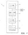
まず図1には、本発明による生理学的モニタリングシステムの1つの実施形態の略図が示される。図1に示されるように、生理学的モニタリングシステム10は、好ましくは、データ収集サブシステム20、制御データ処理サブシステム40、データ送信サブシステム50、データモニタリングサブシステム60、および電源70、例えば電池等、を含む。本明細書において、制御データ処理サブシステム40は、「プロセッササブシステム」、「処理サブシステム」および「データ処理サブシステム」とも呼ばれる。用語「制御データ処理サブシステム」、「プロセッササブシステム」、「処理サブシステム」および「データ処理サブシステム」は、本出願において互換的に使用される。 Referring initially to FIG. 1, a schematic diagram of one embodiment of a physiological monitoring system according to the present invention is shown. As shown in FIG. 1, the physiological monitoring system 10 preferably includes a
データ収集サブシステム
本発明の一つの実施形態によれば、データ収集サブシステム20は、制御データ処理サブシステム40、および、いくつかの実施形態においてはデータモニタリングサブシステム60と連携して、少なくとも1つの呼吸特性、より好ましくは複数の呼吸特性を決定するために採用できる解剖学的パラメータを収集するための手段を含む。解剖学的パラメータは、胸郭および腹部の前後径の変化(または変位)並びに胸壁の軸方向変位を含み得る。上述のパラメータを収集するための手段は、例えばセンサである。センサは、対の電磁石コイルまたは磁力計を含み得る。Data Collection Subsystem According to one embodiment of the present invention, the
本発明は、磁力計および磁力計システムの観点から本明細書に記載されるが、システム内の2つ以上のセンサ間の距離の変化を測定可能なその他の種類のセンサシステムを、磁力計の代わりに、または磁力計に加えて使用できることが理解される。具体的には、本発明は、測定された胸郭および腹部の前後径の変化並びに胸壁の軸方向変位を示すシグナルを収集するための電磁石コイルまたは磁力計の使用に限定されない。上述の解剖学的パラメータを測定するように容易に適合され得る様々な更なる手段および装置が、本発明の範囲内において採用可能である。このような手段および装置には、ホール効果センサおよび電子コンパスセンサが含まれるが、これらに限定されない。本発明に従い、あるセンサから別のセンサに送られたシグナルにおける時間遅延を測定することによりその2つのセンサ間の距離を決定することが可能な無線センサを、磁力計の代わりに、または磁力計に加えて提供可能である。 Although the present invention is described herein in terms of magnetometers and magnetometer systems, other types of sensor systems capable of measuring changes in the distance between two or more sensors in the system are disclosed in magnetometers. It is understood that it can be used instead or in addition to a magnetometer. Specifically, the present invention is not limited to the use of electromagnetic coils or magnetometers to collect signals indicative of changes in measured anterior and posterior diameters of the rib cage and abdomen and axial displacement of the chest wall. Various additional means and devices that can be readily adapted to measure the anatomical parameters described above can be employed within the scope of the present invention. Such means and devices include, but are not limited to, Hall effect sensors and electronic compass sensors. In accordance with the present invention, a wireless sensor capable of determining the distance between two sensors by measuring the time delay in a signal sent from one sensor to another sensor, instead of a magnetometer, or magnetometer In addition to the above.
磁力計(またはその他のセンサ)は、着用可能な衣類、例えばシャツやベストに埋め込むか、またはそれに保持させることができる。着用可能なモニタリング用衣類により、被験者の肌に直接磁力計を取り付ける必要がなくなるので、それに関連した問題がすべて解決される。着用可能なモニタリング用衣類はまた、被験者の胴体上の実質的にすべての適切な(または所望の)位置に、繰り返し、そして簡便に磁力計を配置することを容易にする。 The magnetometer (or other sensor) can be embedded in or held in a wearable garment, such as a shirt or vest. Wearable monitoring clothing eliminates the need to attach a magnetometer directly to the subject's skin, thus solving all of the problems associated with it. The wearable monitoring garment also facilitates repeated and convenient placement of the magnetometer at substantially all suitable (or desired) locations on the subject's torso.
本発明によれば、上述の被験者のパラメータ(または変位)を測定するために、少なくとも1つ、好ましくは2つの磁力計が採用される。本発明のいくつかの実施形態においては、二対の磁力計が採用される。いくつかの実施形態においては、2対より多い複数対の磁力計が採用される。 In accordance with the present invention, at least one, and preferably two, magnetometers are employed to measure the subject parameters (or displacements) described above. In some embodiments of the invention, two pairs of magnetometers are employed. In some embodiments, more than two pairs of magnetometers are employed.
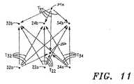
図2には、胸郭、腹部および胸壁の変位を検出および測定するための二対の電磁石コイルの配置の1つの実施形態が示される。図2に示されるように、電磁石コイルは、第1送信コイル22a、第1受信コイル22b、第2送信コイル24a、および第2受信コイル24bを含む。図2において、文字「T」は送信コイルを指し、文字「R」は受信コイルを指すが、コイルはこのような指定に限定されない。本発明の実施形態の電磁石コイルについては、「受信」または「送信」と記載されるが、各受信コイルはそれぞれ、代わりに送信コイルであってよく、また、各送信コイルはそれぞれ、代わりに送信コイルであってよい。コイルはまた、受信および送信の両方の機能を果たしてもよい。 FIG. 2 shows one embodiment of an arrangement of two pairs of electromagnetic coils for detecting and measuring ribcage, abdominal and chest wall displacements. As shown in FIG. 2, the electromagnetic coil includes a
上述の配置および関連する実施形態(以下に記載)の詳細は、2008年9月5日出願の同時係属出願である米国特許出願番号12/231,692、2009年9月1日出願の同時係属出願である米国特許出願番号61/275,576、およびこれと同時出願の、同時係属出願である米国特許出願番号12/869,576に記載され、その全てが、全体を引用することにより本明細書の一部をなす。 Details of the arrangements described above and related embodiments (described below) can be found in co-pending applications filed September 5, 2008, US patent application Ser. No. 12 / 231,692, filed September 1, 2009. All of which are hereby incorporated by reference in their entirety, as described in US patent application Ser. No. 61 / 275,576 and co-pending US patent application Ser. No. 12 / 869,576. .
上述の出願に記載されるように、いくつかの実施形態において、少なくとも受信コイル24bは、送信コイル22aおよび24aそれぞれからのコイルの送信を受信するように適合される(すなわち、少なくとも受信コイル24bは二重機能コイルであってよく、「二重機能コイル」とは、複数の異なる送信コイルからの送信を受信可能なコイルのことを言う)。いくつかの実施形態において、受信コイル22bおよび24bの各々は、送信コイル22aおよび24aの各々からの送信を受信するように適合される。 As described in the above-mentioned application, in some embodiments, at least the receive
次に図3〜図5には、被験者または患者100上に配置されたコイル22a、22b、24aおよび24bが示されている。図3〜図5に示されるように、第1送信コイル22aは、好ましくは被験者100のへそに近接した被験者100の前面101上に配置され、第1受信コイル22bは、好ましくは同じ軸位置に近接した、ただし被験者100の背面102上に配置される。第2受信コイル24bは、好ましくは胸骨の基部に近接した被験者100の前面101上に配置され、第2送信コイル24aは、好ましくは同じ軸位置に近接した、ただし被験者100の背面102上に配置される。 3-5,
同時係属出願である米国特許出願番号12/231,692号に記載されるように、送信コイル22aおよび24aと、受信コイル22bおよび24bの位置は、逆であってもよい(すなわち、送信コイル22aおよび受信コイル24bは、被験者100の背面102上に配置されてよく、送信コイル24aおよび受信コイル22bは、被験者100の前面101上に配置されてよい)。また、送信コイル22aおよび24aの両方が被験者100の前面101または背面102上に配置され、受信コイル22bおよび24bが反対側に配置されてもよい。 As described in co-pending US patent application Ser. No. 12 / 231,692, the positions of transmit
図3に戻ると、矢印23は、胸壁、またはこの場合には、モニターされる剣状骨とへその間の距離(xiphi-umbilical distance)(Xi)を示す。矢印25は、モニターされる胸郭の距離を示し、矢印29は、モニターされる腹部の距離を示す。Returning to FIG. 3,
1つの実施形態において、コイル24bが二重機能コイルである場合、被験者または患者100が呼吸をすると、胸郭および腹部の変位(すなわち、コイル22aと22bおよび24aと24bの各対の間の距離の変化であり、それぞれ矢印29および矢印25で示される)が、対のコイル22aと22bおよび24aと24bの間の測定された電圧の変化から決定される。矢印23で示される胸壁の軸方向変位(例えば、剣状骨とへその間の距離(xiphiumbilical distance)(Xi))も、送信コイル22aと受信コイル24bとの間の測定された電圧の変化から決定される。 In one embodiment, if the
上述のように、解剖学的パラメータを収集するために、2対より多い複数対の電磁石コイルが採用され得る。2009年9月1日出願の米国特許出願番号61/275,575号、およびこれと同時出願の、同時係属出願である米国特許出願番号12/869,582号は、その両方共、その全体を引用することにより本明細書の一部をなすが、それらに記載されるように、被験者の解剖学的に適切な位置上に更なる電磁石コイルを追加することにより、2対のコイルの実施形態よりも多数の重要な利点が提供される。そうした利点の1つは、胸壁の動き並びにそれと呼吸活性および呼吸に関連する事象、例えば話す、くしゃみをする、笑う、咳をする等との関係についての更なる(および関連する)データおよび/または情報の提供である。 As described above, more than two pairs of electromagnet coils may be employed to collect anatomical parameters. U.S. Patent Application No. 61 / 275,575, filed September 1, 2009, and co-pending U.S. Patent Application No. 12 / 869,582, both of which are incorporated by reference in their entirety. As part of this specification, but as described therein, by adding additional electromagnetic coils on the subject's anatomically appropriate location, more than two-coil embodiments can be achieved. Significant benefits are provided. One such advantage is additional (and related) data on chest wall movement and its relationship to respiratory activity and breathing related events such as speaking, sneezing, laughing, coughing, and / or Information provision.
更に、コイル(およびその配置)を追加した結果による電磁石コイルの送信の複数の単一、交差、および相互の軸(multiple single, cross, and interaction axes)は、胸壁の容積の変化の非常に正確な定量化を提供すると共に、胸壁の形および歩行する被験者の動きの三次元モデリング、並びに換気力学(例えば胸壁の区画における同期運動および非同期運動)の評価および定量化を容易にする。 In addition, the multiple single, cross, and interaction axes of the electromagnetic coil transmission resulting from the addition of the coil (and its placement) are very accurate in changing the chest wall volume. As well as three-dimensional modeling of the shape of the chest wall and the movement of the walking subject, as well as the evaluation and quantification of ventilation dynamics (eg, synchronous and asynchronous motion in the chest wall compartment).
図6〜図17には、いくつかの複数対の電磁石コイルの配置の詳細が記載されている。しかし、本発明は、本明細書に記載された複数対のコイルの実施形態に限定されないことが理解されるべきである。実際、この複数対のコイルの実施形態は、任意の数の更なる対の電磁石コイル(例えば3、4、5、6、7、8、9、10個等)を含み得る。例えば、3つの磁力計(例えば電磁石コイル)を使用する実施形態においては、該3つの電磁石コイルが複数対として機能し得ることが理解される。具体的には、これらのコイルを第1、第2および第3コイルとすると、第1コイルは第2コイルと対を形成することができ、この第1コイルはまた、第3コイルとも対を形成することができる。更に、第2コイルはまた、第3コイルとも対を形成することができる。このように、3つの電磁石コイルを利用した磁力計システムは、1対、2対または3対を形成するように構成され得る。第1、第2および第3コイルの各々は、シグナルを送信、シグナルを受信、またはシグナルを送信および受信するように構成され得る。磁力計は、複数の他の磁力計と接続してもよく、従って、特定の磁力計が、複数対のうちの一部を形成し得る。追加コイルの位置およびその機能はまた、本発明の範囲内において、容易に修正し、および/または特定の適用向けに適合させることができる。 6 to 17 describe details of the arrangement of several pairs of electromagnetic coils. However, it should be understood that the present invention is not limited to the multiple-paired coil embodiments described herein. Indeed, this multiple pair coil embodiment may include any number of additional pairs of electromagnetic coils (eg, 3, 4, 5, 6, 7, 8, 9, 10, etc.). For example, in an embodiment using three magnetometers (eg, electromagnet coils), it is understood that the three electromagnet coils can function as multiple pairs. Specifically, if these coils are first, second, and third coils, the first coil can form a pair with the second coil, and the first coil can also pair with the third coil. Can be formed. Furthermore, the second coil can also form a pair with the third coil. Thus, a magnetometer system utilizing three electromagnetic coils can be configured to form one, two or three pairs. Each of the first, second and third coils may be configured to transmit a signal, receive a signal, or transmit and receive a signal. A magnetometer may be connected to a plurality of other magnetometers, and thus a particular magnetometer may form part of a plurality of pairs. The location of the additional coil and its function can also be easily modified and / or adapted for a particular application within the scope of the present invention.
まず図6〜図8には、複数対のコイルの配置に関する1つの実施形態が示される。図7に示されるように、この実施形態も同様に、電磁石コイル22a、22b、24aおよび24bを含む。本発明によれば、コイル22a、22b、24aおよび24bに関連する上述の2対のコイルの実施形態のいずれもが、本発明の複数対のコイルの実施形態と共に採用され得る。 First, FIGS. 6 to 8 show one embodiment relating to the arrangement of a plurality of pairs of coils. As shown in FIG. 7, this embodiment similarly includes
また、図6および図7に示されるように、複数対のコイルの配置は、更に少なくとも2対の電磁石コイル:第3送信コイル32a、第3受信コイル32b、第4送信コイル34a、および第4受信コイル34bを更に含む。 Further, as shown in FIGS. 6 and 7, the arrangement of the plurality of pairs of coils further includes at least two pairs of electromagnetic coils: a
いくつかの実施形態において、受信コイル32bおよび34bのうちの少なくとも1つは、二重機能コイルであり、従って、送信コイル32a、22aおよび34aの各々からの送信を受信するように適合される。いくつかの実施形態において、受信コイル32bおよび34bの各々は、送信コイル32a、22aおよび34aの各々からの送信を受信するように適合される。 In some embodiments, at least one of the receive
図8および図9には、被験者または患者100上に配置されたコイル22a、22b、24a、24b、32a、32b、34aおよび34bが示される。図8および図9に示されるように、第1送信コイル22aは、好ましくは、被験者100のへそに近接した被験者100の前面101上に配置され、第1受信コイル22bは、好ましくは同じ軸位置に近接した、ただし被験者100の背面102上に配置される。第2受信コイル24bは、好ましくは胸骨の基部に近接した被験者100の前面101上に配置され、第2送信コイル24aは、同じ軸位置に近接した、ただし被験者100の背面102上に配置される。 8 and 9
第3送信コイル32aは、好ましくは被験者100の前面101上に、第1送信コイル22aの右側に軸方向に間隔を空けて配置される。第4送信コイル34aは、好ましくは被験者100の前面101上に、第1送信コイル22aの左側に軸方向に間隔を空けて配置される。例示された実施形態において、送信コイル32a、22aおよび34aの各々は、好ましくは同じ軸平面に近接して配置される(図6および図7において「AP1」で示される)。The
第3受信コイル32bは、好ましくは被験者100の前面101上に、第2受信コイル24bの右側に軸方向に間隔を空けて配置される。第4受信コイル34bは、好ましくは被験者100の前面101上に、第2受信コイル24bの左側に軸方向に間隔を空けて配置される。好ましくは、受信コイル32b、24bおよび34bの各々も同様に、同じ軸平面に近接して配置される(図6および図7において「AP2」で示される)。The
コイル32a、32b、34aおよび34bの軸方向の間隔は、多くの場合、被験者(例えば大人、女性、男性、若者等)の体のサイズおよび構造に依存する。コイル間の距離はまた、必要な、または所望の測定の精度の度合いによって異なり得る。 The axial spacing of the
先に示したように、複数対のコイルの配置の1つの重要な利点は、胸壁の形および歩行する被験者の動きの三次元モデリング、並びに換気力学(例えば胸壁の区画における同期運動および非同期運動)の評価および定量化を容易にする、複数の単一、交差、および相互のコイル送信軸の提供である。 As indicated above, one important advantage of the arrangement of multiple pairs of coils is the three-dimensional modeling of the chest wall shape and the movement of the walking subject, and ventilation dynamics (eg, synchronous and asynchronous motion in the chest wall compartment). Providing a plurality of single, crossed, and mutual coil transmission axes that facilitate the evaluation and quantification of
複数対のコイルの配置についての更なる重要な利点は、複数対のコイルを用いた胸壁の同時モニタリングによって、胸壁のリアルタイムな三次元モデルが作成可能であることである。 A further important advantage for the placement of multiple pairs of coils is that a real-time three-dimensional model of the chest wall can be created by simultaneous monitoring of the chest wall using multiple pairs of coils.
図10〜図12には、本発明の複数対のコイルに関する3つの実施形態によって提供されるコイルの送信軸の略図がいくつか示される。まず図10にコイル送信の例が示され、ここで、受信コイル32b、24b、34bおよび22bの各々は、単機能コイルである。受信コイル32bは、送信コイル22aからの送信T32を受信するように適合される。受信コイル24bは、送信コイル22aからの送信T22を受信するように適合される。受信コイル34bは、送信コイル34aからの送信T34を受信するように適合される。受信コイル22bは、送信コイル24aからの送信T24を受信するように適合される。10-12 show some schematic views of the transmit axes of the coils provided by the three embodiments of the present invention for multiple pairs of coils. First, an example of coil transmission is shown in FIG. 10, where each of the receiving
図12にはコイル送信の別の例が示され、ここで、受信コイル24bは二重機能コイルである。受信コイル32bは、送信コイル32aからの送信T32を受信するように適合され、受信コイル34bは、送信コイル34aからの送信T34を受信するように適合され、受信コイル22bは、送信コイル24aからの送信T24を受信するように適合される。しかし、受信コイル24bは、送信コイル32aからの送信T32、送信コイル22aからの送信T22、送信コイル34aからの送信T34、および送信コイル24aからの送信T24を受信するように適合される。FIG. 12 shows another example of coil transmission, where the receive
図11において、受信コイル32b、24b、34bおよび22bの各々は二重機能コイルである。図11に示されるように、受信コイル32bは、送信コイル32aからの送信T32、送信コイル22aからの送信T22、送信コイル34aからの送信T34、および送信コイル24aからの送信T24を受信するように適合される。受信コイル24b、34bおよび22bもまた、送信コイル32aからの送信T32、送信コイル22aからの送信T22、送信コイル34aからの送信T34、および送信コイル24aからの送信T24を受信するように適合される。In FIG. 11, each of the receiving
図13〜図17には、本発明の範囲内において採用できる、更なる複数対のコイルの配置が示される。まず図13には、複数対のコイルの配置が示され、ここで、更なる2対のコイル、32aと32b、および34aと34bは、被験者100の前面101上に不均一に配置される。示されるように、更なるコイルは、被験者100の胴体上の任意の適切な(または所望の)位置に配置され得る。 FIGS. 13-17 illustrate further multiple pairs of coil arrangements that can be employed within the scope of the present invention. First, FIG. 13 shows an arrangement of a plurality of pairs of coils, where two further pairs of coils, 32a and 32b, and 34a and 34b are non-uniformly arranged on the
図14に示されるように、更なるコイル(例えば、送信コイル36aと受信コイル36bの対、および送信コイル38aと受信コイル38bの対)も、被験者100の背面102上に配置され得る。コイル36a、36b、38aおよび38bは、図14に示されるように均一に配置されても、あるいは図15に示されるように不均一に配置されてもよい。 As shown in FIG. 14, additional coils (eg, a pair of transmit coil 36a and receive
図16〜図17には、別の複数対のコイルの配置が示され、ここで、更なるコイルが被験者100の胴体上に配置される。図16に示されるように、更なるコイル(例えば、送信コイル33aと受信コイル33bの対、および送信コイル35aと受信コイル35bの対)が、被験者100の前面101上に配置され得る。また、更なるコイル(例えば、送信コイル37aと受信コイル37bの対、および送信コイル39aと受信コイル39bの対)が、被験者100の両側上に配置され得る。 FIGS. 16-17 show another arrangement of multiple pairs of coils, where additional coils are placed on the torso of
更に、本明細書に開示された送信コイルおよび受信コイルは、必ずしも1対1の対である必要はない。例えば、単一の受信コイルが、複数の送信コイルからの送信を受信するように構成されてもよく、単一の送信コイルが、複数の受信コイルへ送信するように構成されてもよい。 Further, the transmit and receive coils disclosed herein do not necessarily have to be a one-to-one pair. For example, a single receive coil may be configured to receive transmissions from multiple transmit coils, and a single transmit coil may be configured to transmit to multiple receive coils.
本発明の複数のコイルの実施形態は、図6〜図17に示された複数対のコイルの実施形態に限定されない。複数対のコイルの実施形態は、任意の数の更なる電磁石コイルを含み得ることが再度強調される。また、更なるコイルの位置およびそれらの機能もまた、本発明の範囲内において、容易に修正し、および/または特定の適用向けに適合させることができる。 The multiple coil embodiments of the present invention are not limited to the multiple pairs of coil embodiments shown in FIGS. It is again emphasized that multiple pairs of coil embodiments may include any number of additional electromagnetic coils. Also, additional coil positions and their functions can also be easily modified and / or adapted for specific applications within the scope of the present invention.
データ収集サブシステム20はまた、被験者100の向きおよび/または動き(例えば空間パラメータ)を直接モニタリングする手段をも含み得る。このような手段は、光学エンコーダー、近接およびホール効果スイッチ、レーザー干渉計、加速度計、ジャイロスコープ、および/または全地球測位システム(GPS)を含み得る。このような手段から得られたデータは、身体活動に従事する被験者のパフォーマンスパラメータまたは特性、例えば、被験者または被験者の一部の速度または加速度、ペース、ストライドの長さ、ストライド数、反復数等を提供し得る。
1つの実施形態において、被験者の向きおよび動きを直接モニタリングする手段は、少なくとも1つの多機能の慣性センサ(例えば3軸の加速度計または3軸のジャイロスコープ)を含む。当技術分野において周知のように、被験者の向きおよび動きは、多機能の慣性センサによって送信されるシグナルまたはデータから容易に決定できる。 In one embodiment, the means for directly monitoring subject orientation and movement includes at least one multifunctional inertial sensor (eg, a 3-axis accelerometer or a 3-axis gyroscope). As is well known in the art, subject orientation and movement can be readily determined from signals or data transmitted by multifunctional inertial sensors.
本発明によれば、加速度計は、被験者100上の任意の解剖学的に適切な位置に配置できる。本発明の1つの実施形態において、加速度計(図8において「AC1」で示される)は、被験者100の胸骨の基部に近接して配置される。In accordance with the present invention, the accelerometer can be placed at any anatomically appropriate location on the subject 100. In one embodiment of the present invention, an accelerometer (shown as “AC1 ” in FIG. 8) is placed proximate to the base of the subject's 100 sternum.
いくつかの実施形態において、複数の加速度計(または被験者100の向きおよび/または動きをモニタリングするその他の手段)は、被験者100の体の上の種々の位置に配置され得る。そのように配置することにより、被験者100の体のある部分と相対的であると共に環境に相対的である、被験者100の体の別の部分の動きに関連するデータの収集が可能となり得る。 In some embodiments, multiple accelerometers (or other means of monitoring subject 100 orientation and / or movement) may be placed at various locations on the subject's 100 body. Such an arrangement may allow for the collection of data relating to movement of another part of the body of the subject 100 that is relative to one part of the body of the subject 100 and relative to the environment.
いくつかの実施形態において、精神または感情のパラメータ、例えばストレスレベルまたは意欲の程度を含むパフォーマンスパラメータが決定され得る。このようなパラメータが示すものとしては、例えば胴体の角度または足の当たり方(foot strike)の特性が含まれ得、上述の被験者100の向きおよび/または動きをモニタリングする手段によってモニタリングされ得る。 In some embodiments, performance parameters including mental or emotional parameters, eg, stress level or degree of motivation, may be determined. Such parameters may include, for example, torso angle or foot strike characteristics and may be monitored by means of monitoring the orientation and / or movement of the subject 100 described above.
データ収集サブシステム20は、モニターされる被験者100に関連する1つ以上の生理学的特性をモニターおよび記録するように適合された、少なくとも1つの更なる生理学的センサ(好ましくは複数の更なる生理学的センサ)を更に含み得る。生理学的センサは、脳、心臓およびその他の筋肉の電気的活動(例えばEEG、ECG、EMG)、脈拍数、血中酸素飽和度(例えばSpO2)、皮膚温および中核体温をモニターし記録するように適合されたセンサを含み得るが、これらに限定されない。測定および/または計算された生理学的パラメータには、例えば、心拍数、呼吸速度、血中酸素濃度、血流量、水分補給状態、消費カロリー、筋肉疲労および/または体温が含まれ得る。
こうした更なるセンサは、もちろん、被験者上の多様な解剖学的に適切な位置に配置できる。例としては、第1センサ(例えば脈拍数センサ)は、脈拍数をモニターするように被験者100の心臓に近接して配置することができ、第2センサ(例えばマイクロホン)は、咽喉から出てくる音(例えば、咳を反映する音)をモニターするように被験者100の咽喉に近接して配置することができる。 Such additional sensors can of course be placed at various anatomically appropriate locations on the subject. As an example, a first sensor (eg, a pulse rate sensor) can be placed in proximity to the heart of subject 100 to monitor the pulse rate, and a second sensor (eg, a microphone) comes out of the throat. It can be placed in close proximity to the throat of subject 100 to monitor sounds (eg, sounds reflecting cough).
データ収集サブシステム20は、モニターされる被験者100によって生成される音をモニターするための1つ以上の音声センサ(例えばマイクロホン)、並びに、モニターされる被験者100およびモニタリングステーションまたは個人(例えばアスレチック・トレーナーまたは医療関係者等)による、およびその間の双方向の通信を可能にするスピーカーも含み得る。 The
本発明の例示的実施形態によれば、対のコイル(例えば電磁石コイル22a、22bと24a、24b)および上述の更なるセンサは、種々の好適な手段によって被験者100上または被験者100に近接して配置することができる。このように、対のコイルおよび/または更なるセンサは、例えば、被験者100に直接取り付けることができ、および/または被験者100が着用する衣類(例えば運動用の衣料)またはアクセサリー(例えば時計、ベルト)に含有させることができる。 According to an exemplary embodiment of the present invention, a pair of coils (eg,
2009年9月1日出願の米国特許出願番号61/275,633号、および、これと同時出願の、同時係属出願である米国特許出願番号12/869,627号は、各々、その全体を引用することにより本明細書の一部をなすが、それらに記載されるように、対のコイル、更なるセンサ、処理およびモニタリングシステム(もし採用される場合、例えばローカルデータユニット(LDU))、そして関連する配線、ケーブル、ならびにその他の電力およびシグナル送信の装置および/またはシステムも、モニターされる被験者が楽に着用できる着用可能な衣類またはアイテムに埋め込まれるか、またはそれによって保持され得る。 U.S. Patent Application No. 61 / 275,633, filed September 1, 2009, and co-pending U.S. Patent Application No. 12 / 869,627, each of which is incorporated herein by reference in its entirety. As part of the specification, but described therein, a pair of coils, additional sensors, processing and monitoring systems (if employed, eg, local data unit (LDU)), and associated wiring, Cables and other power and signal transmission devices and / or systems may also be embedded in or retained by wearable clothing or items that can be comfortably worn by the subject being monitored.
2009年9月1日出願の米国特許出願番号61/275,576号、および、これと同時出願の、同時係属出願である米国特許出願番号12/869,576号もまた、各々、その全体を引用することにより本明細書の一部をなすが、磁力計に基づいた着用可能なモニタリング用衣類を開示している。 U.S. Patent Application No. 61 / 275,576, filed September 1, 2009, and co-pending U.S. Patent Application No. 12 / 869,576, each of which is also incorporated by reference in its entirety. As part of this specification, a wearable monitoring garment based on a magnetometer is disclosed.
制御データ処理サブシステム
制御データ処理サブシステム40は、データ収集サブシステム20、ひいては、対の電磁石コイル(例えばコイル22a、22b、24a、24b、32a、32b、34a、34b)およびその機能並びにコイル送信の送信と受信(例えば送信T32、T22、T34およびT24)、それに加えてデータ送信サブシステム50およびデータモニタリングサブシステム60を制御するためのプログラム、指示、関連するアルゴリズムおよびパラメータを含む。以下に詳細を説明する。Control Data Processing Subsystem The control
制御データ処理サブシステム40は、モニターされる被験者100に関連する生理学的情報を決定するために、電磁石コイル(例えばコイル22a、22b、24a、24b、32a、32b、34aおよび34b)からのコイル送信またはシグナルを回収および処理するため;更なる空間パラメータおよび生理学的センサによって送信される更なるシグナルを回収、処理および解釈するため(以下に説明);ならびに、選択的コイルデータ、生理学的および空間のパラメータ、生理学的特性、ならびに被験者の情報を本発明のデータモニタリングサブシステム60に送信するために、更にプログラムおよび適合される。 The control
制御データ処理サブシステム40は、回収されたコイル送信またはシグナル(例えば胸郭、腹部および胸壁の測定された変位)から少なくとも1つの呼吸特性(例えばVT)を決定するための少なくとも1つの「n自由度」モデルまたはアルゴリズムを更に含む。The control
制御データ処理サブシステム40はまた、好ましくは、データ収集サブシステム20によって収集されたデータ(例えば以下に述べるように、更なる空間パラメータおよび生理学的センサによって送信されたコイル送信およびシグナル)の多変数解析を行うように設計および適合された好適なアルゴリズムを含む。 The control
制御データ処理サブシステム40はまた、好ましくは、測定された複数の相互作用的な胸壁の変位から呼吸特性、パラメータおよびステータスを決定するように設計および適合された好適なアルゴリズムを含む。アルゴリズムはまた、好ましくは、呼吸特性(および/またはパラメータ)の決定の正確性を高めるために、非呼吸運動(例えば胴体をひねる動き)に関連する測定された胸壁の変位を割り引くように適合される。 The control
制御データ処理サブシステム40は更に、好ましくは、測定された複数の相互作用的な胸壁の変位から被験者100の胸壁の三次元モデルを生成するための、好適なプログラム、アルゴリズムおよび指示を含む。 The control
制御データ処理サブシステム40はまた、好ましくは、測定された複数の相互作用的な胸壁の変位から、追加の、そして場合によっては相互に関連する解剖学的パラメータ、例えば曲げる、ひねる、咳をする等を決定するようにプログラムおよび適合される。場合によっては、制御データ処理サブシステム40は、コイル送信とそれに関連する胸壁パラメータとの記憶された選択的組合せ(例えば「正常な呼吸と曲げる」、「正常な呼吸と咳をする」等)を、測定された胸壁の変位を反映する回収されたコイル送信と比較するようにプログラムおよび適合される。 The control
一例として、1つの実施形態において、「正常な呼吸と胴体をひねる」と定義される(またはそれを反映する)第1胸壁パラメータ(CWP1)が、制御データ処理サブシステム40に記憶される。第1胸壁パラメータ(CWP1)に関連するコイル送信およびデータは、受信コイル24bが受信する送信T32、T22、T34およびT24を含み、変位x、yおよびzを示すことができる。As an example, in one embodiment, a first chest wall parameter (CWP1 ) defined as (or reflecting) “normal breathing and torso twisting” is stored in the control
被験者100をモニター中、類似のコイル送信が受信コイル24bによって受信される可能性がある。すると、制御データ処理サブシステム40は、検出された(または回収された)送信を、記憶された送信およびそれに関連する胸壁パラメータと比較して、胸壁の動きと、ひいてはそれに基づく呼吸活性(この場合、「正常な呼吸と胴体をひねる」)を(リアルタイムに)決定する。 While monitoring subject 100, a similar coil transmission may be received by receive
いくつかの実施形態においては、加速度計によって送信されるシグナル(例えば空間パラメータシグナル)が、検出されたコイル送信と共に採用され、モニターされる被験者の胸壁の動きおよび関連する呼吸活性が決定および分類される。上述の実施形態において、各記憶された胸壁パラメータはまた、胸壁パラメータと関連する空間パラメータシグナル(例えば「正常な呼吸と胴体をひねる」)も含む。制御データ処理サブシステム40は、回収されたコイル送信および空間パラメータシグナルを、記憶された送信および空間パラメータシグナル、並びにそれらと関連する胸壁パラメータと比較して、胸壁の動き、そして、ひいてはそれに基づく呼吸活性を決定するように適合される。 In some embodiments, a signal transmitted by an accelerometer (eg, a spatial parameter signal) is employed with the detected coil transmission to determine and classify the subject's chest wall motion and associated respiratory activity to be monitored. The In the above-described embodiment, each stored chest wall parameter also includes a spatial parameter signal (eg, “twice normal breathing and torso”) associated with the chest wall parameter. The control
場合によっては、制御データ処理サブシステム40は、回収されたコイル送信、空間パラメータシグナルおよび音声シグナルに基づいて胸壁の動きおよび呼吸活性を決定するようにプログラムおよび適合される。上述の実施形態において、データ収集サブシステム20は、音声センサ、例えばマイクロホン等も含んでよく、これは、被験者100上の解剖学的に適切な位置に(例えば咽喉に近接して)配置される。 In some cases, the control
この場合、各記憶された胸壁パラメータは、胸壁パラメータと関連する少なくとも1つの音声パラメータ(例えば>N db、音声シグナルに基づく)も含む(例えば正常な呼吸と咳をする)。コイル送信、空間パラメータシグナルおよび音声シグナルを受信するとすぐに、制御データ処理サブシステム40は、回収されたコイル送信、空間パラメータシグナルおよび音声シグナルを、記憶された送信、空間パラメータシグナルおよび音声パラメータ、並びにそれに関連する胸壁パラメータと比較し、それに基づいた胸壁の動きおよび呼吸活性を決定する(例えば「正常な呼吸と咳をする」)。 In this case, each stored chest wall parameter also includes at least one voice parameter (eg,> N db, based on the voice signal) associated with the chest wall parameter (eg, normal breathing and coughing). As soon as the coil transmission, spatial parameter signal and voice signal are received, the control
データモニタリングサブシステム
データモニタリングサブシステム60は、コイル送信またはシグナル(例えば送信T32、T22、T34およびT24)を受信し、そしていくつかの実施形態においては、選択的にモニターするように、そしてそれに関連するパラメータ(例えば選択的軸に沿った変位)、および/または胸壁パラメータ(例えばCWP1)、および/または呼吸特性(例えばVT)もしくは事象を表示するように、設計および適合される。このような表示は、多様な媒体、例えば個人用デジタル補助装置(PDA)、携帯電話、および/またはコンピュータのモニター等を通じて行い得る。Data Monitoring Subsystem
データモニタリングサブシステム60は、更に好ましくは、選択的な被験者のパラメータ、特性、情報および警報または警告を表示するように、設計および適合される。データモニタリングサブシステムはまた、データを表示する、またはデータを聴覚的に送信するようにも適合され得る。聴覚的に示されるデータは、ボイスメッセージ、音楽、または事象を示すその他のノイズであり得る。データモニタリングサブシステムは、聴覚的データを表示するために、ヘッドフォンまたはスピーカーがデータモニタリングサブシステムに接続できるように適合され得、それは無線でも有線でもよい。 The
場合によっては、データモニタリングサブシステム60はまた、空間パラメータシグナルおよび更なる解剖学的および生理学的センサによって送信されるシグナル(例えば皮膚温またはSpO2を示すシグナル)を受信し、そしていくつかの実施形態においては選択的にモニターするように、そしてそれに関連するパラメータおよび情報を表示するようにも適合される。パラメータはアスリートの身体活動に関連し得る。測定される、および/または計算される身体的もしくは解剖学的パラメータは、例えば、時間、場所、距離、速度、ペース、ストライド数、ストライドの長さ、ストライド速度(stride rate)、および/または高度を含み得る。測定および/または計算される生理学的パラメータは、例えば、心拍数、呼吸速度、血中酸素濃度、血流量、水分補給状態、消費カロリー、筋肉疲労および/または体温を含み得る。ある実施形態において、パフォーマンスパラメータは、精神または感情のパラメータ、例えばストレスレベルまたは意欲の程度をも含み得る。精神および感情のパラメータは、アスリートに質問をすることにより、または走っている間に、例えば胴体の角度もしくは足の当たり方の特性等を測定することにより、直接的もしくは間接的に測定および/または計算され得る。In some cases, the
いくつかの実施形態において、データモニタリングサブシステム60は、ローカル電子モジュールまたはローカルデータユニット(LDU)を含む。LDUと関連して使用される用語「ローカル」は、LDUが、コイルを含有する着用可能な衣類の上または中など、電磁石コイルの近くに配置されることを意味する(以下に詳しく説明する)。LDUは、好ましくは、コイル送信(またはシグナル)を受信およびモニターし、コイル送信を前処理し、そしてコイル送信および関連データを記憶するように適合される。 In some embodiments, the
いくつかの実施形態において、LDUはまた、空間パラメータ送信(またはシグナル)ならびに更なる解剖学的および生理学的センサ(採用された場合)によって送信される更なるシグナルを受信およびモニターし、シグナルを前処理し、そして、シグナルおよび関連データを記憶するように適合される。 In some embodiments, the LDU also receives and monitors spatial parameter transmissions (or signals) and additional signals transmitted by additional anatomical and physiological sensors (if employed) and pre-signals. It is adapted to process and store signals and associated data.
データ送信サブシステム
データ送信サブシステム50は、(1)制御シグナルをデータ収集サブシステム20へ送信する、(2)コイル送信(またはシグナル)をコイルから制御データ処理サブシステム40へ送信する、および(3)コイル送信(またはシグナル)および関連するパラメータ、生理学的特性、空間パラメータ、並びに被験者の情報を含むデータおよび情報を、制御データ処理サブシステム40からデータモニタリングサブシステム60へ送信するための通信プロトコルを含む。Data transmission subsystem The data transmission subsystem 50 (1) transmits control signals to the
いくつかの実施形態において、データ収集サブシステム20と制御データ処理サブシステム40との間の通信リンクは、導線または類似の直接的通信手段を含む。いくつかの実施形態において、データ収集サブシステム20と制御データ処理サブシステム40との間の通信リンクは、制御データ処理サブシステム40とデータモニタリングサブシステム60との間のものと同様、無線リンク(wireless (or radio) link)を含む。データ収集サブシステム20と制御データ処理サブシステム40との間の通信リンクと、制御データ処理サブシステム40とデータモニタリングサブシステム60との間の通信リンクとは、同じタイプのリンクである必要はない。 In some embodiments, the communication link between the
データの無線通信へのアプローチは、継続的な、または一定間隔でスケジュールされたデータ送信に依存してよく、典型的には、1つのモードの無線送信技術を採用する。対照的に、本発明のデータ送信サブシステム20は多モード通信手段を含み、これが、単一無線モードでは効果がないであろう広範囲の設定(settings)において獲得されるべきデータモニタリングサブシステム60(またはその他の所望の機器もしくはシステム)への効果的な通信を可能にする。 The approach to wireless communication of data may rely on continuous or regularly scheduled data transmission and typically employs one mode of wireless transmission technology. In contrast, the
本発明の1つの実施形態において、多モード通信手段は、複数の無線サブシステムを含む。本発明によれば、無線サブシステムは、例えばグローバル・システム・フォー・モバイル・コミュニケーションズ(Global System for Mobile Communications)(GSM)およびブルートゥース(BlueTooth(登録商標))システムを含む複数の公知のシステムを含み得る。 In one embodiment of the invention, the multi-mode communication means includes a plurality of radio subsystems. In accordance with the present invention, wireless subsystems include a plurality of known systems including, for example, Global System for Mobile Communications (GSM) and Bluetooth (BlueTooth®) systems. obtain.
1つの実施形態において、多モード通信手段は、多重周波数無線送信を含む。周波数は定常状態および/またはランダムであってよい。 In one embodiment, the multi-mode communication means includes multi-frequency radio transmission. The frequency may be steady state and / or random.
本発明の例示的な実施形態によれば、データ送信サブシステム50は、上述の多モード通信手段を制御するためのアルゴリズムおよびプログラミングを更に含んでもよい。このような制御は、予めプログラムされたシグナルの送信(例えば、シグナルが示す特性が関連すると見なされたときの送信、特定の活動期間中の送信、あるいは、フィードバックまたは別のモードの状態に応じた、ある特定のモードによる送信)を含み得る。 According to an exemplary embodiment of the present invention, the
本発明による多モード通信はまた、複数の機器との通信も可能にする。例えば、ある製品は、無線センサネットワーク技術、例えばANT+を使用して第1機器に対して心拍数のデータを通信し、別の無線技術、例えば低消費電力ブルートゥース(Bluetooth Low Energy)を使用して携帯電話に対して速度のデータを通信することができる。 Multi-mode communication according to the present invention also allows communication with multiple devices. For example, one product communicates heart rate data to a first device using wireless sensor network technology, such as ANT +, and uses another wireless technology, such as Bluetooth Low Energy. Speed data can be communicated to a mobile phone.
多モード通信の使用により、システムパフォーマンスの最適化が可能となる。例えば、データが強化(data-intense)された送信、例えば詳しい心拍数のシグナルは、大量のデータの扱いが可能な第1送信規格または周波数によって送信できる。より単純な送信、例えば速度/距離のデータ点は、必要な電力がより少ない場合があり第1送信規格にくらべてその他の利点を提供する第2送信規格または周波数によって送信できる。 The use of multi-mode communication can optimize system performance. For example, data-intense transmissions, such as detailed heart rate signals, can be transmitted by a first transmission standard or frequency that can handle large amounts of data. Simpler transmissions, such as speed / distance data points, can be transmitted over a second transmission standard or frequency that may require less power and provide other advantages over the first transmission standard.
上述のように、本発明は、本明細書に記載されたシステムおよび関連する方法に限定されないことが理解されるべきである。実際、本発明によれば、本発明の多モード通信手段は、先に参照したシステムおよび方法を含め、種々の生理学的および/または解剖学的モニタリングシステムおよび方法と共に採用することができる。 As mentioned above, it should be understood that the present invention is not limited to the systems and associated methods described herein. Indeed, according to the present invention, the multi-mode communication means of the present invention can be employed with a variety of physiological and / or anatomical monitoring systems and methods, including the systems and methods referred to above.
当業者には容易に理解できるであろうが、上述のリアルタイムのシグナル収集および処理能力と連動した多モード通信手段は「スマートな」通信構造を創り出し、これが、電池の効率を最大にし、広範な環境にわたる接続性を保証し、データが関連するときのみ送信されることを可能にする。 As will be readily appreciated by those skilled in the art, the multi-mode communication means coupled with the real-time signal collection and processing capabilities described above creates a “smart” communication structure, which maximizes battery efficiency and is Ensure connectivity across the environment and allow data to be sent only when relevant.
本発明の更に別の利点は、磁力計間の前面と背面間の分離(front to back separation between magnetometers)、および異なるセットの磁力計の垂直方向の分離の測定(vertical separation between different sets of magnetometers)を可能にするモニタリングシステムと連動した多モード通信手段の使用である。これにより、システムが、歩く動きによって起こる動きアーチファクトから所望のシグナルおよび情報を分離することが可能となる。 Yet another advantage of the present invention is that the front to back separation between magnetometers and the vertical separation between different sets of magnetometers. The use of multi-mode communication means in conjunction with a monitoring system that enables This allows the system to separate the desired signal and information from motion artifacts caused by walking motion.
本発明の更なる利点および適用は、以下の出願明細書に開示されたシステムおよび方法を参照すれば明らかである:これと同時出願の米国特許出願番号12/869,578号;同時出願の米国特許出願番号12/869,582号;同時出願の米国特許出願番号12/869,576号;同時出願の米国特許出願番号12/869,585号;同時出願の米国特許出願番号12/869,627号;同時出願の米国特許出願番号12/869,625号;および同時出願の米国特許出願番号12/869,586号。これら各々が、その全体を引用することにより本明細書の一部をなす。 Further advantages and applications of the present invention will be apparent with reference to the systems and methods disclosed in the following application specifications: co-pending US patent application Ser. No. 12 / 869,578; co-pending US patent application. No. 12 / 869,582; co-pending US patent application No. 12 / 869,576; co-pending US patent application No. 12 / 869,585; co-pending US patent application No. 12 / 869,627; co-pending US patent application No. 12 / 869,625; and co-filed US patent application Ser. No. 12 / 869,586. Each of which is hereby incorporated by reference in its entirety.
本発明の精神および範囲を逸脱しない範囲において、当業者は、本発明に種々の変更および改善を加えて、種々の使用法および条件に適合するようにすることができる。よって、これらの変更および改善は、適切かつ公平に、本発明に相当する全範囲内であるように意図される。
Without departing from the spirit and scope of this invention, one of ordinary skill can make various changes and modifications to the invention to adapt it to various usages and conditions. Accordingly, these changes and improvements are intended to be within the full scope corresponding to the present invention, appropriately and fairly.
Claims (30)
Translated fromJapanese被験者の体の上に保持されるデータ収集サブシステムであって、該データ収集サブシステムは、被験者をモニタリングして第1シグナルおよび第2シグナルを生成するように構成され、第1シグナルおよび第2シグナルは、被験者のパラメータを示す、データ収集サブシステム;および
第1シグナルおよび第2シグナルをデータ収集サブシステムからデータモニタリングサブシステムへ送信するように構成されたデータ送信サブシステム;を含み、
データ送信サブシステムは、第1送信モードを使用して第1シグナルを送信するように構成され、
データ送信サブシステムは、第2送信モードを使用して第2シグナルを送信するように構成され、
第2送信モードは第1送信モードと異なる、システム。A system for transmitting information about a subject engaged in physical activity, the system comprising:
A data collection subsystem retained on the subject's body, the data collection subsystem configured to monitor the subject to generate a first signal and a second signal, wherein the first signal and the second signal The signal is a data collection subsystem indicative of the subject's parameters; and
A data transmission subsystem configured to transmit a first signal and a second signal from the data collection subsystem to the data monitoring subsystem;
The data transmission subsystem is configured to transmit a first signal using a first transmission mode;
The data transmission subsystem is configured to transmit the second signal using the second transmission mode;
The system in which the second transmission mode is different from the first transmission mode.
データ収集サブシステムを用いて第1シグナルおよび第2シグナルを生成する工程であって、該第1シグナルおよび第2シグナルの各々が、被験者のパラメータを示す情報を含有する、工程;
第1送信モードを使用して第1シグナルを送信する工程であって、第1シグナルが、データ送信サブシステムによってデータモニタリングサブシステムへ送信される、工程;および
第2送信モードを使用して第2シグナルを送信する工程であって、該第2送信モードは第1送信モードと異なり、第2シグナルが、データ送信サブシステムによってデータモニタリングサブシステムへ送信される、工程
を含む、方法。A method for transmitting information about a subject engaged in physical activity comprising:
Generating a first signal and a second signal using a data collection subsystem, wherein each of the first signal and the second signal contains information indicative of a parameter of the subject;
Transmitting a first signal using a first transmission mode, wherein the first signal is transmitted by a data transmission subsystem to a data monitoring subsystem; and
Transmitting a second signal using a second transmission mode, the second transmission mode being different from the first transmission mode, wherein the second signal is transmitted by the data transmission subsystem to the data monitoring subsystem; , Including steps.
被験者の胴体の少なくとも一部を覆うように適合されたモニタリング用衣類と;
第1センサおよび第2センサを含むセンササブシステムであって、該第1センサおよび第2センサが、その間の距離の変化に反応し、該センササブシステムが、第1シグナルおよび第2シグナルを生成および送信するように構成され、第1シグナルが、第1センサと第2センサの間の距離の変化を示し、第2シグナルが、被験者の生理学的パラメータを示し、第1センサおよび第2センサが衣類に組み込まれ、被験者が該衣類を着用したときに、第1センサおよび第2センサが被験者の胸部に近接する、センササブシステムと;
該センササブシステムと接続し、第1シグナルを受信するように構成されたプロセッサであって、センササブシステムを制御し、第1シグナルを処理するようにプログラムおよび適合された、プロセッサと;
第1シグナルおよび第2シグナルを該プロセッサからデータモニタリングサブシステムへ送信するように構成されたデータ送信サブシステムと
を含み、
該データ送信サブシステムが、第1送信モードを使用して第1シグナルを送信するように構成され、
該データ送信サブシステムが、第2送信モードを使用して第2シグナルを送信するように構成され、
第2送信モードが第1送信モードと異なる、フィットネスモニタリングシステム。
A fitness monitoring system for monitoring physiological parameters of a subject engaged in physical activity, the fitness monitoring system:
Monitoring clothing adapted to cover at least a portion of the subject's torso;
A sensor subsystem including a first sensor and a second sensor, wherein the first sensor and the second sensor are responsive to a change in distance therebetween, and the sensor subsystem generates a first signal and a second signal And the first signal indicates a change in distance between the first sensor and the second sensor, the second signal indicates a physiological parameter of the subject, and the first sensor and the second sensor A sensor subsystem incorporated into the garment, wherein the first sensor and the second sensor are proximate to the subject's chest when the subject wears the garment;
A processor connected to the sensor subsystem and configured to receive a first signal, the processor being programmed and adapted to control the sensor subsystem and process the first signal;
A data transmission subsystem configured to transmit a first signal and a second signal from the processor to a data monitoring subsystem;
The data transmission subsystem is configured to transmit a first signal using a first transmission mode;
The data transmission subsystem is configured to transmit a second signal using a second transmission mode;
A fitness monitoring system in which the second transmission mode is different from the first transmission mode.
Applications Claiming Priority (4)
| Application Number | Priority Date | Filing Date | Title |
|---|---|---|---|
| US27558709P | 2009-09-01 | 2009-09-01 | |
| US61/275,587 | 2009-09-01 | ||
| US12/869,592 | 2010-08-26 | ||
| US12/869,592US8971936B2 (en) | 2009-09-01 | 2010-08-26 | Multimodal method and system for transmitting information about a subject |
Related Child Applications (1)
| Application Number | Title | Priority Date | Filing Date |
|---|---|---|---|
| JP2017096367ADivisionJP2017205513A (en) | 2009-09-01 | 2017-05-15 | Multimodal method and system for transmitting information about subject |
Publications (2)
| Publication Number | Publication Date |
|---|---|
| JP2011139886Atrue JP2011139886A (en) | 2011-07-21 |
| JP6203468B2 JP6203468B2 (en) | 2017-09-27 |
Family
ID=43031520
Family Applications (2)
| Application Number | Title | Priority Date | Filing Date |
|---|---|---|---|
| JP2010196122AActiveJP6203468B2 (en) | 2009-09-01 | 2010-09-01 | Multi-mode method and system for transmitting information about a subject |
| JP2017096367APendingJP2017205513A (en) | 2009-09-01 | 2017-05-15 | Multimodal method and system for transmitting information about subject |
Family Applications After (1)
| Application Number | Title | Priority Date | Filing Date |
|---|---|---|---|
| JP2017096367APendingJP2017205513A (en) | 2009-09-01 | 2017-05-15 | Multimodal method and system for transmitting information about subject |
Country Status (4)
| Country | Link |
|---|---|
| US (2) | US8971936B2 (en) |
| EP (1) | EP2289404B1 (en) |
| JP (2) | JP6203468B2 (en) |
| CA (1) | CA2714103C (en) |
Families Citing this family (69)
| Publication number | Priority date | Publication date | Assignee | Title |
|---|---|---|---|---|
| IL130818A (en) | 1999-07-06 | 2005-07-25 | Intercure Ltd | Interventive-diagnostic device |
| EP2324760B1 (en)* | 2000-04-17 | 2019-07-24 | Adidas AG | System for ambulatory monitoring of physiological signs |
| US8672852B2 (en) | 2002-12-13 | 2014-03-18 | Intercure Ltd. | Apparatus and method for beneficial modification of biorhythmic activity |
| US9492084B2 (en) | 2004-06-18 | 2016-11-15 | Adidas Ag | Systems and methods for monitoring subjects in potential physiological distress |
| WO2006008745A2 (en) | 2004-07-23 | 2006-01-26 | Intercure Ltd. | Apparatus and method for breathing pattern determination using a non-contact microphone |
| US8475371B2 (en) | 2009-09-01 | 2013-07-02 | Adidas Ag | Physiological monitoring garment |
| US8971936B2 (en)* | 2009-09-01 | 2015-03-03 | Adidas Ag | Multimodal method and system for transmitting information about a subject |
| US10852069B2 (en) | 2010-05-04 | 2020-12-01 | Fractal Heatsink Technologies, LLC | System and method for maintaining efficiency of a fractal heat sink |
| JP6004444B2 (en) | 2010-10-29 | 2016-10-05 | オーピクス メディカル テクノロジーズ インコーポレイテッドOrpyx Medical Technologies Inc. | Peripheral sensory and supersensory substitution system |
| TW201225914A (en)* | 2010-12-23 | 2012-07-01 | Ind Tech Res Inst | Intestinal peristalsis detecting device and system and method thereof |
| JP2014504943A (en) | 2011-02-07 | 2014-02-27 | ニュー バランス アスレティック シュー,インコーポレーテッド | System and method for monitoring athletic performance |
| US10363453B2 (en) | 2011-02-07 | 2019-07-30 | New Balance Athletics, Inc. | Systems and methods for monitoring athletic and physiological performance |
| US9767257B2 (en) | 2011-03-31 | 2017-09-19 | Adidas Ag | Group performance monitoring system and method |
| US8818478B2 (en) | 2011-03-31 | 2014-08-26 | Adidas Ag | Sensor garment |
| US9317660B2 (en) | 2011-03-31 | 2016-04-19 | Adidas Ag | Group performance monitoring system and method |
| US9141759B2 (en) | 2011-03-31 | 2015-09-22 | Adidas Ag | Group performance monitoring system and method |
| US9339691B2 (en) | 2012-01-05 | 2016-05-17 | Icon Health & Fitness, Inc. | System and method for controlling an exercise device |
| US9737261B2 (en) | 2012-04-13 | 2017-08-22 | Adidas Ag | Wearable athletic activity monitoring systems |
| US9257054B2 (en) | 2012-04-13 | 2016-02-09 | Adidas Ag | Sport ball athletic activity monitoring methods and systems |
| US10922383B2 (en) | 2012-04-13 | 2021-02-16 | Adidas Ag | Athletic activity monitoring methods and systems |
| US9504414B2 (en) | 2012-04-13 | 2016-11-29 | Adidas Ag | Wearable athletic activity monitoring methods and systems |
| US10212986B2 (en) | 2012-12-09 | 2019-02-26 | Arris Enterprises Llc | System, apparel, and method for identifying performance of workout routines |
| US9278255B2 (en) | 2012-12-09 | 2016-03-08 | Arris Enterprises, Inc. | System and method for activity recognition |
| US9500464B2 (en) | 2013-03-12 | 2016-11-22 | Adidas Ag | Methods of determining performance information for individuals and sports objects |
| US10304325B2 (en) | 2013-03-13 | 2019-05-28 | Arris Enterprises Llc | Context health determination system |
| WO2014153158A1 (en) | 2013-03-14 | 2014-09-25 | Icon Health & Fitness, Inc. | Strength training apparatus with flywheel and related methods |
| US10288881B2 (en) | 2013-03-14 | 2019-05-14 | Fresenius Medical Care Holdings, Inc. | Wearable interface for remote monitoring and control of a medical device |
| MX2015015896A (en) | 2013-05-21 | 2016-06-29 | Orpyx Medical Technologies Inc | Pressure data acquisition assembly. |
| CN105848733B (en) | 2013-12-26 | 2018-02-13 | 爱康保健健身有限公司 | Magnetic resistance mechanism in hawser apparatus |
| EP3111351B1 (en)* | 2014-02-27 | 2023-12-20 | Technion Research & Development Foundation Ltd. | Device and method for monitoring respiratory effort using energy index |
| US10433612B2 (en) | 2014-03-10 | 2019-10-08 | Icon Health & Fitness, Inc. | Pressure sensor to quantify work |
| JP6137031B2 (en)* | 2014-04-11 | 2017-05-31 | トヨタ自動車株式会社 | Vehicle information terminal and power generation information collection system |
| US9849361B2 (en) | 2014-05-14 | 2017-12-26 | Adidas Ag | Sports ball athletic activity monitoring methods and systems |
| US10523053B2 (en) | 2014-05-23 | 2019-12-31 | Adidas Ag | Sport ball inductive charging methods and systems |
| WO2015191445A1 (en) | 2014-06-09 | 2015-12-17 | Icon Health & Fitness, Inc. | Cable system incorporated into a treadmill |
| WO2015195965A1 (en) | 2014-06-20 | 2015-12-23 | Icon Health & Fitness, Inc. | Post workout massage device |
| US9710711B2 (en) | 2014-06-26 | 2017-07-18 | Adidas Ag | Athletic activity heads up display systems and methods |
| WO2016077489A1 (en) | 2014-11-11 | 2016-05-19 | Innovaura Corporation | Heart rate monitor |
| US10478668B2 (en) | 2014-11-24 | 2019-11-19 | Adidas Ag | Activity monitoring base station |
| US11562417B2 (en) | 2014-12-22 | 2023-01-24 | Adidas Ag | Retail store motion sensor systems and methods |
| US10391361B2 (en) | 2015-02-27 | 2019-08-27 | Icon Health & Fitness, Inc. | Simulating real-world terrain on an exercise device |
| US10194835B2 (en)* | 2015-04-01 | 2019-02-05 | Medical Research Infrastructure And Health Services Fund Of The Tel Aviv Medical Center | Method of monitoring volumetric change of a lung |
| US9968270B1 (en) | 2016-01-06 | 2018-05-15 | Verily Life Sciences Llc | Determination of pulse rate recovery |
| US10272317B2 (en) | 2016-03-18 | 2019-04-30 | Icon Health & Fitness, Inc. | Lighted pace feature in a treadmill |
| US10493349B2 (en) | 2016-03-18 | 2019-12-03 | Icon Health & Fitness, Inc. | Display on exercise device |
| US10625137B2 (en) | 2016-03-18 | 2020-04-21 | Icon Health & Fitness, Inc. | Coordinated displays in an exercise device |
| US10588560B2 (en)* | 2016-09-21 | 2020-03-17 | Cm Hk Limited | Systems and methods for facilitating exercise monitoring with real-time heart rate monitoring and motion analysis |
| US10671705B2 (en) | 2016-09-28 | 2020-06-02 | Icon Health & Fitness, Inc. | Customizing recipe recommendations |
| CN110325110B (en) | 2016-11-10 | 2022-08-09 | 纽约州立大学研究基金会 | Systems, methods, and biomarkers for airway obstruction |
| AU2018214450B2 (en) | 2017-02-06 | 2023-08-24 | Western Sydney Local Health District | Methods and apparatuses for monitoring cardiac dysfunction |
| US10699247B2 (en) | 2017-05-16 | 2020-06-30 | Under Armour, Inc. | Systems and methods for providing health task notifications |
| US11723579B2 (en) | 2017-09-19 | 2023-08-15 | Neuroenhancement Lab, LLC | Method and apparatus for neuroenhancement |
| US11717686B2 (en) | 2017-12-04 | 2023-08-08 | Neuroenhancement Lab, LLC | Method and apparatus for neuroenhancement to facilitate learning and performance |
| US12280219B2 (en) | 2017-12-31 | 2025-04-22 | NeuroLight, Inc. | Method and apparatus for neuroenhancement to enhance emotional response |
| US11273283B2 (en) | 2017-12-31 | 2022-03-15 | Neuroenhancement Lab, LLC | Method and apparatus for neuroenhancement to enhance emotional response |
| US10675473B2 (en)* | 2018-01-11 | 2020-06-09 | Medtronic, Inc. | Implantable medical device coils |
| EP3746012A4 (en)* | 2018-02-02 | 2021-12-15 | Vyas, Dinesh | DEVICES AND METHODS FOR THE MANAGEMENT AND PREVENTION OF HERNIA AND OTHER MUSCLE SKELETON INJURIES |
| US11364361B2 (en) | 2018-04-20 | 2022-06-21 | Neuroenhancement Lab, LLC | System and method for inducing sleep by transplanting mental states |
| US11000191B2 (en) | 2018-08-20 | 2021-05-11 | Thomas Jefferson University | Acoustic sensor and ventilation monitoring system |
| WO2020041167A2 (en) | 2018-08-20 | 2020-02-27 | Thomas Jefferson University | Acoustic sensor and ventilation monitoring system |
| US11213225B2 (en) | 2018-08-20 | 2022-01-04 | Thomas Jefferson University | Acoustic sensor and ventilation monitoring system |
| EP3849410A4 (en) | 2018-09-14 | 2022-11-02 | Neuroenhancement Lab, LLC | SLEEP ENHANCEMENT SYSTEM AND METHOD |
| US11031128B2 (en) | 2019-01-25 | 2021-06-08 | Fresenius Medical Care Holdings, Inc. | Augmented reality-based training and troubleshooting for medical devices |
| EP3725232A1 (en)* | 2019-04-17 | 2020-10-21 | Koninklijke Philips N.V. | A patch sensor for a medical device |
| US11786694B2 (en) | 2019-05-24 | 2023-10-17 | NeuroLight, Inc. | Device, method, and app for facilitating sleep |
| EP4013297A4 (en) | 2019-08-16 | 2023-12-13 | Poltorak Technologies, LLC | DEVICE AND METHOD FOR MEDICAL DIAGNOSTICS |
| US20220407550A1 (en)* | 2020-09-16 | 2022-12-22 | Genki Instruments ehf. | Smart ring |
| CN115137300A (en)* | 2021-03-31 | 2022-10-04 | 京东方科技集团股份有限公司 | Signal detection method, signal detection device, electronic apparatus, and storage medium |
| CN113418630A (en)* | 2021-07-07 | 2021-09-21 | 西安华英特新能源工程技术有限公司 | Temperature measurement sampling automatic centering clamping mechanism |
Citations (12)
| Publication number | Priority date | Publication date | Assignee | Title |
|---|---|---|---|---|
| US4258718A (en)* | 1979-04-16 | 1981-03-31 | Goldman Michael D | Measuring respiratory air volume |
| JP2000049656A (en)* | 1998-07-17 | 2000-02-18 | Lucent Technol Inc | Radio communication system |
| US6102856A (en)* | 1997-02-12 | 2000-08-15 | Groff; Clarence P | Wearable vital sign monitoring system |
| JP2003010138A (en)* | 2001-04-16 | 2003-01-14 | Nippon Koden Corp | Medical telemeter system |
| JP2003530184A (en)* | 2000-04-17 | 2003-10-14 | ビボメトリックス,インコーポレイテッド | Monitoring device, system, and recording medium for wearing physiologically monitor physiological signs |
| US20040122334A1 (en)* | 2002-09-19 | 2004-06-24 | Alfred E. Mann Institute For Biomedical Engineering At The University Of Southern | Vantilation and volume change measurements using permanent magnet and magnet sensor affixed to body |
| JP2005066323A (en)* | 2003-07-02 | 2005-03-17 | Commissariat A L'energie Atomique | Portable detector for measuring movement of person wearing it and the method |
| JP2005312901A (en)* | 2004-03-31 | 2005-11-10 | Takuya Okamoto | Apparatus for detecting prone sleep of baby |
| JP2006204742A (en)* | 2005-01-31 | 2006-08-10 | Konica Minolta Sensing Inc | Method and system for evaluating sleep, its operation program, pulse oxymeter, and system for supporting sleep |
| JP2006263339A (en)* | 2005-03-25 | 2006-10-05 | Konica Minolta Medical & Graphic Inc | Image obtaining apparatus and image obtaining system |
| JP2007525236A (en)* | 2003-04-10 | 2007-09-06 | ヴィヴォメトリクス・インコーポレーテッド | Respiratory event detection system and method |
| JP2009106374A (en)* | 2007-10-26 | 2009-05-21 | Panasonic Electric Works Co Ltd | Gait information display system |
Family Cites Families (77)
| Publication number | Priority date | Publication date | Assignee | Title |
|---|---|---|---|---|
| US4033332A (en)* | 1972-09-11 | 1977-07-05 | Cavitron Corporation | Activity and respiration monitor |
| US3831586A (en)* | 1972-11-16 | 1974-08-27 | P Petit | Respiration monitor |
| US4267845A (en)* | 1978-10-05 | 1981-05-19 | Robertson Jr Charles H | Method and apparatus for measuring pulmonary ventilation |
| US4494553A (en)* | 1981-04-01 | 1985-01-22 | F. William Carr | Vital signs monitor |
| IL86759A (en)* | 1988-06-16 | 1992-09-06 | Dror Nedivi | Medical monitoring system |
| CA2147478A1 (en)* | 1992-11-09 | 1994-05-26 | Michael D. Halleck | Apparatus and method for remote monitoring of physiological parameters |
| DE4329898A1 (en)* | 1993-09-04 | 1995-04-06 | Marcus Dr Besson | Wireless medical diagnostic and monitoring device |
| US5738102A (en)* | 1994-03-31 | 1998-04-14 | Lemelson; Jerome H. | Patient monitoring system |
| US5825293A (en)* | 1996-09-20 | 1998-10-20 | Ahmed; Adel A. | Apparatus and method for monitoring breathing magnetically |
| US6198394B1 (en)* | 1996-12-05 | 2001-03-06 | Stephen C. Jacobsen | System for remote monitoring of personnel |
| US6015388A (en)* | 1997-03-17 | 2000-01-18 | Nims, Inc. | Method for analyzing breath waveforms as to their neuromuscular respiratory implications |
| DE69841846D1 (en)* | 1997-03-17 | 2010-09-30 | Adidas Ag | INFORMATION RECONDITIONING SYSTEM FOR PHYSIOLOGICAL SIGNALS |
| US5906004A (en)* | 1998-04-29 | 1999-05-25 | Motorola, Inc. | Textile fabric with integrated electrically conductive fibers and clothing fabricated thereof |
| US6268725B1 (en)* | 1998-04-29 | 2001-07-31 | Medtronic, Inc. | Flux-gate magnetometer with drive signal for reducing effects of electromagnetic interference |
| US6080690A (en)* | 1998-04-29 | 2000-06-27 | Motorola, Inc. | Textile fabric with integrated sensing device and clothing fabricated thereof |
| US6790183B2 (en)* | 1998-10-14 | 2004-09-14 | Raymond L. H. Murphy | Method and apparatus for displaying body sounds and performing diagnosis based on body sound analysis |
| CA2348399A1 (en)* | 1998-10-30 | 2000-05-11 | Volusense As | Volumetric physiological measuring system |
| AUPP974599A0 (en)* | 1999-04-14 | 1999-05-06 | Resmed Limited | Detection and classification of breathing patterns |
| JP3820811B2 (en)* | 1999-08-02 | 2006-09-13 | 株式会社デンソー | Respiratory system disease monitoring device |
| AU1210301A (en) | 1999-10-18 | 2001-04-30 | Electric Power Research Institute, Inc. | Apparatus and method for assessing pulmonary ventilation |
| US6527729B1 (en)* | 1999-11-10 | 2003-03-04 | Pacesetter, Inc. | Method for monitoring patient using acoustic sensor |
| US6600949B1 (en)* | 1999-11-10 | 2003-07-29 | Pacesetter, Inc. | Method for monitoring heart failure via respiratory patterns |
| US6727197B1 (en)* | 1999-11-18 | 2004-04-27 | Foster-Miller, Inc. | Wearable transmission device |
| WO2001054575A1 (en)* | 2000-01-26 | 2001-08-02 | Vsm Medtech Ltd. | Continuous blood pressure monitoring method and apparatus |
| AU2001244517A1 (en) | 2000-04-07 | 2001-10-23 | Remo Ehf. | Breathing movement measurements and apparatus |
| US6468234B1 (en)* | 2000-07-14 | 2002-10-22 | The Board Of Trustees Of The Leland Stanford Junior University | SleepSmart |
| US6454719B1 (en)* | 2000-08-01 | 2002-09-24 | Pacesetter, Inc. | Apparatus and method for diagnosis of cardiac disease using a respiration monitor |
| US6858006B2 (en)* | 2000-09-08 | 2005-02-22 | Wireless Medical, Inc. | Cardiopulmonary monitoring |
| US6517497B2 (en)* | 2000-12-13 | 2003-02-11 | Ge Medical Systems Information Technologies, Inc. | Method and apparatus for monitoring respiration using signals from a piezoelectric sensor mounted on a substrate |
| US6341504B1 (en)* | 2001-01-31 | 2002-01-29 | Vivometrics, Inc. | Composite elastic and wire fabric for physiological monitoring apparel |
| US6834436B2 (en)* | 2001-02-23 | 2004-12-28 | Microstrain, Inc. | Posture and body movement measuring system |
| JP2002370183A (en)* | 2001-06-15 | 2002-12-24 | Yamaha Motor Co Ltd | Monitor and monitoring system |
| US7267262B1 (en)* | 2001-08-06 | 2007-09-11 | Seecontrol, Inc. | Method and apparatus confirming return and/or pick-up valuable items |
| US7016396B2 (en)* | 2001-11-13 | 2006-03-21 | Telcordia Technologies, Inc. | Unitary bluetooth-enabled terminal having multiple radio interfaces |
| AU2003263476A1 (en)* | 2002-10-11 | 2004-05-04 | Koninklijke Philips Electronics N.V. | Power saving uplink for biosensors |
| US7009511B2 (en)* | 2002-12-17 | 2006-03-07 | Cardiac Pacemakers, Inc. | Repeater device for communications with an implantable medical device |
| US20040133079A1 (en)* | 2003-01-02 | 2004-07-08 | Mazar Scott Thomas | System and method for predicting patient health within a patient management system |
| US20080082018A1 (en) | 2003-04-10 | 2008-04-03 | Sackner Marvin A | Systems and methods for respiratory event detection |
| KR20060007445A (en) | 2003-05-27 | 2006-01-24 | 인터디지탈 테크날러지 코포레이션 | Multi-mode Radios with Interference Cancellation Circuits |
| US20050020299A1 (en) | 2003-06-23 | 2005-01-27 | Quorum Systems, Inc. | Time interleaved multiple standard single radio system apparatus and method |
| EP2382920A1 (en)* | 2003-08-20 | 2011-11-02 | Philometron, Inc. | Hydration monitoring |
| WO2005032447A2 (en)* | 2003-08-22 | 2005-04-14 | Foster-Miller, Inc. | Physiological monitoring garment |
| EP1533678A1 (en)* | 2003-11-24 | 2005-05-25 | Sony International (Europe) GmbH | Physical feedback channel for entertaining or gaming environments |
| US7278966B2 (en)* | 2004-01-31 | 2007-10-09 | Nokia Corporation | System, method and computer program product for managing physiological information relating to a terminal user |
| US20050261559A1 (en)* | 2004-05-18 | 2005-11-24 | Mumford John R | Wireless physiological monitoring system |
| EP1773185A4 (en) | 2004-06-18 | 2009-08-19 | Vivometrics Inc | Systems and methods for real-time physiological monitoring |
| WO2006034291A2 (en)* | 2004-09-21 | 2006-03-30 | Vivometrics, Inc. | Inductive plethysmographic sensors, monitors, and apparel |
| WO2006047295A1 (en)* | 2004-10-21 | 2006-05-04 | Baker Hughes Incorporated | Enhancing the quality and resolution of an image generated from single or multiple sources |
| US9059782B2 (en) | 2005-06-01 | 2015-06-16 | Broadcom Corporation | Method and system for antenna and radio front-end topologies for a system-on-a-chip (SOC) device that combines bluetooth and IEEE 802.11 b/g WLAN technologies |
| US8028443B2 (en)* | 2005-06-27 | 2011-10-04 | Nike, Inc. | Systems for activating and/or authenticating electronic devices for operation with footwear |
| US8033996B2 (en)* | 2005-07-26 | 2011-10-11 | Adidas Ag | Computer interfaces including physiologically guided avatars |
| US7398168B2 (en)* | 2005-09-08 | 2008-07-08 | Genscape Intangible Holding, Inc. | Method and system for monitoring power flow through an electric power transmission line |
| WO2007069111A2 (en) | 2005-12-15 | 2007-06-21 | Koninklijke Philips Electronics N.V. | Device for assessing the physical condition of a person |
| US7978081B2 (en)* | 2006-01-09 | 2011-07-12 | Applied Technology Holdings, Inc. | Apparatus, systems, and methods for communicating biometric and biomechanical information |
| DE602006008046D1 (en)* | 2006-02-01 | 2009-09-03 | Jonathan Hylton | METHOD AND SYSTEM FOR PROVIDING THE CONNECTIVITY OF A MOBILE OBJECT TO AN EXTERNAL NETWORK |
| US7607243B2 (en)* | 2006-05-03 | 2009-10-27 | Nike, Inc. | Athletic or other performance sensing systems |
| US8475387B2 (en)* | 2006-06-20 | 2013-07-02 | Adidas Ag | Automatic and ambulatory monitoring of congestive heart failure patients |
| US7628074B2 (en)* | 2007-03-15 | 2009-12-08 | Mitsubishi Electric Research Laboratories, Inc. | System and method for motion capture in natural environments |
| WO2008127720A2 (en)* | 2007-04-13 | 2008-10-23 | University Of Florida Research Foundation, Inc. | Atomic magnetometer sensor array magnetoencephalogram systems and methods |
| WO2008134583A1 (en)* | 2007-04-26 | 2008-11-06 | Ray Gregory C | Precision athletic aptitude and performance data analysis system |
| US8702430B2 (en)* | 2007-08-17 | 2014-04-22 | Adidas International Marketing B.V. | Sports electronic training system, and applications thereof |
| US8926509B2 (en)* | 2007-08-24 | 2015-01-06 | Hmicro, Inc. | Wireless physiological sensor patches and systems |
| HUP0700807A2 (en) | 2007-12-13 | 2009-06-29 | Jozsef Vincze | Arrangement and method for detection and/or measurement of respiration |
| JP2009178381A (en)* | 2008-01-31 | 2009-08-13 | Nippon Koden Corp | Biological information telemeter system |
| EP2283417B1 (en)* | 2008-05-12 | 2014-01-29 | QUALCOMM Incorporated | Implementation of arbitrary galois field arithmetic on a programmable processor |
| US9462844B2 (en)* | 2008-06-13 | 2016-10-11 | Nike, Inc. | Footwear having sensor system |
| US20100022861A1 (en)* | 2008-07-28 | 2010-01-28 | Medtronic, Inc. | Implantable optical hemodynamic sensor including an extension member |
| US8790273B2 (en)* | 2008-09-05 | 2014-07-29 | Adidas | Noninvasive method and system for measuring pulmonary ventilation |
| US20100249541A1 (en)* | 2009-03-27 | 2010-09-30 | LifeWatch Corp. | Methods and Apparatus for Processing Physiological Data Acquired from an Ambulatory Physiological Monitoring Unit |
| US8033959B2 (en)* | 2009-05-18 | 2011-10-11 | Adidas Ag | Portable fitness monitoring systems, and applications thereof |
| US8209773B2 (en)* | 2009-07-22 | 2012-07-03 | Karen Bothwell | Configurable supportive protection system and methods |
| US8475371B2 (en) | 2009-09-01 | 2013-07-02 | Adidas Ag | Physiological monitoring garment |
| US9526419B2 (en)* | 2009-09-01 | 2016-12-27 | Adidas Ag | Garment for physiological characteristics monitoring |
| US8971936B2 (en)* | 2009-09-01 | 2015-03-03 | Adidas Ag | Multimodal method and system for transmitting information about a subject |
| US9041528B2 (en)* | 2010-02-26 | 2015-05-26 | Thl Holding Company, Llc | Bridge device for use in a system for monitoring protective headgear |
| US8976724B2 (en)* | 2010-04-20 | 2015-03-10 | Zomm, Llc | Method and system for repackaging wireless data |
| US8696271B2 (en) | 2010-11-12 | 2014-04-15 | Cory Dickey | Fastening nut and tool bit holding system |
- 2010
- 2010-08-26USUS12/869,592patent/US8971936B2/ennot_activeExpired - Fee Related
- 2010-08-31CACA2714103Apatent/CA2714103C/ennot_activeExpired - Fee Related
- 2010-09-01EPEP10174882.0Apatent/EP2289404B1/enactiveActive
- 2010-09-01JPJP2010196122Apatent/JP6203468B2/enactiveActive
- 2015
- 2015-02-27USUS14/633,621patent/US9826903B2/enactiveActive
- 2017
- 2017-05-15JPJP2017096367Apatent/JP2017205513A/enactivePending
Patent Citations (12)
| Publication number | Priority date | Publication date | Assignee | Title |
|---|---|---|---|---|
| US4258718A (en)* | 1979-04-16 | 1981-03-31 | Goldman Michael D | Measuring respiratory air volume |
| US6102856A (en)* | 1997-02-12 | 2000-08-15 | Groff; Clarence P | Wearable vital sign monitoring system |
| JP2000049656A (en)* | 1998-07-17 | 2000-02-18 | Lucent Technol Inc | Radio communication system |
| JP2003530184A (en)* | 2000-04-17 | 2003-10-14 | ビボメトリックス,インコーポレイテッド | Monitoring device, system, and recording medium for wearing physiologically monitor physiological signs |
| JP2003010138A (en)* | 2001-04-16 | 2003-01-14 | Nippon Koden Corp | Medical telemeter system |
| US20040122334A1 (en)* | 2002-09-19 | 2004-06-24 | Alfred E. Mann Institute For Biomedical Engineering At The University Of Southern | Vantilation and volume change measurements using permanent magnet and magnet sensor affixed to body |
| JP2007525236A (en)* | 2003-04-10 | 2007-09-06 | ヴィヴォメトリクス・インコーポレーテッド | Respiratory event detection system and method |
| JP2005066323A (en)* | 2003-07-02 | 2005-03-17 | Commissariat A L'energie Atomique | Portable detector for measuring movement of person wearing it and the method |
| JP2005312901A (en)* | 2004-03-31 | 2005-11-10 | Takuya Okamoto | Apparatus for detecting prone sleep of baby |
| JP2006204742A (en)* | 2005-01-31 | 2006-08-10 | Konica Minolta Sensing Inc | Method and system for evaluating sleep, its operation program, pulse oxymeter, and system for supporting sleep |
| JP2006263339A (en)* | 2005-03-25 | 2006-10-05 | Konica Minolta Medical & Graphic Inc | Image obtaining apparatus and image obtaining system |
| JP2009106374A (en)* | 2007-10-26 | 2009-05-21 | Panasonic Electric Works Co Ltd | Gait information display system |
Also Published As
| Publication number | Publication date |
|---|---|
| JP2017205513A (en) | 2017-11-24 |
| EP2289404B1 (en) | 2018-05-16 |
| US20110054270A1 (en) | 2011-03-03 |
| JP6203468B2 (en) | 2017-09-27 |
| US9826903B2 (en) | 2017-11-28 |
| CA2714103C (en) | 2018-04-17 |
| CA2714103A1 (en) | 2011-03-01 |
| EP2289404A1 (en) | 2011-03-02 |
| US20150164322A1 (en) | 2015-06-18 |
| US8971936B2 (en) | 2015-03-03 |
Similar Documents
| Publication | Publication Date | Title |
|---|---|---|
| JP6203468B2 (en) | Multi-mode method and system for transmitting information about a subject | |
| JP5841716B2 (en) | Method and system for interpreting and analyzing physiological information, performance information and situation information | |
| JP6216105B2 (en) | Physiological database and system for population modeling and method of population modeling | |
| JP5841320B2 (en) | Non-invasive methods and systems for monitoring physiological characteristics and exercise performance | |
| JP5677788B2 (en) | Non-invasive methods and systems for monitoring physiological properties | |
| US9326705B2 (en) | Method and system for monitoring physiological and athletic performance characteristics of a subject | |
| US10123724B2 (en) | Breath volume monitoring system and method | |
| CA2714028A1 (en) | Noninvasive method and system for monitoring physiological characteristics and athletic performance |
Legal Events
| Date | Code | Title | Description |
|---|---|---|---|
| A621 | Written request for application examination | Free format text:JAPANESE INTERMEDIATE CODE: A621 Effective date:20130620 | |
| A131 | Notification of reasons for refusal | Free format text:JAPANESE INTERMEDIATE CODE: A131 Effective date:20140624 | |
| A977 | Report on retrieval | Free format text:JAPANESE INTERMEDIATE CODE: A971007 Effective date:20140627 | |
| A601 | Written request for extension of time | Free format text:JAPANESE INTERMEDIATE CODE: A601 Effective date:20140924 | |
| A602 | Written permission of extension of time | Free format text:JAPANESE INTERMEDIATE CODE: A602 Effective date:20140929 | |
| A02 | Decision of refusal | Free format text:JAPANESE INTERMEDIATE CODE: A02 Effective date:20150331 | |
| A521 | Request for written amendment filed | Free format text:JAPANESE INTERMEDIATE CODE: A523 Effective date:20150731 | |
| A911 | Transfer to examiner for re-examination before appeal (zenchi) | Free format text:JAPANESE INTERMEDIATE CODE: A911 Effective date:20150807 | |
| A912 | Re-examination (zenchi) completed and case transferred to appeal board | Free format text:JAPANESE INTERMEDIATE CODE: A912 Effective date:20150904 | |
| A601 | Written request for extension of time | Free format text:JAPANESE INTERMEDIATE CODE: A601 Effective date:20160823 | |
| A601 | Written request for extension of time | Free format text:JAPANESE INTERMEDIATE CODE: A601 Effective date:20160921 | |
| A521 | Request for written amendment filed | Free format text:JAPANESE INTERMEDIATE CODE: A523 Effective date:20161122 | |
| A601 | Written request for extension of time | Free format text:JAPANESE INTERMEDIATE CODE: A601 Effective date:20170310 | |
| A601 | Written request for extension of time | Free format text:JAPANESE INTERMEDIATE CODE: A601 Effective date:20170413 | |
| A521 | Request for written amendment filed | Free format text:JAPANESE INTERMEDIATE CODE: A523 Effective date:20170515 | |
| RD03 | Notification of appointment of power of attorney | Free format text:JAPANESE INTERMEDIATE CODE: A7423 Effective date:20170525 | |
| A521 | Request for written amendment filed | Free format text:JAPANESE INTERMEDIATE CODE: A523 Effective date:20170609 | |
| A61 | First payment of annual fees (during grant procedure) | Free format text:JAPANESE INTERMEDIATE CODE: A61 Effective date:20170830 | |
| R150 | Certificate of patent or registration of utility model | Ref document number:6203468 Country of ref document:JP Free format text:JAPANESE INTERMEDIATE CODE: R150 | |
| R250 | Receipt of annual fees | Free format text:JAPANESE INTERMEDIATE CODE: R250 | |
| R250 | Receipt of annual fees | Free format text:JAPANESE INTERMEDIATE CODE: R250 | |
| R250 | Receipt of annual fees | Free format text:JAPANESE INTERMEDIATE CODE: R250 | |
| R250 | Receipt of annual fees | Free format text:JAPANESE INTERMEDIATE CODE: R250 | |
| R250 | Receipt of annual fees | Free format text:JAPANESE INTERMEDIATE CODE: R250 |