JP2011138011A - Information processing apparatus, program, information processing method, and map data - Google Patents
Information processing apparatus, program, information processing method, and map dataDownload PDFInfo
- Publication number
- JP2011138011A JP2011138011AJP2009298148AJP2009298148AJP2011138011AJP 2011138011 AJP2011138011 AJP 2011138011AJP 2009298148 AJP2009298148 AJP 2009298148AJP 2009298148 AJP2009298148 AJP 2009298148AJP 2011138011 AJP2011138011 AJP 2011138011A
- Authority
- JP
- Japan
- Prior art keywords
- point
- deformed map
- unit
- points
- position information
- Prior art date
- Legal status (The legal status is an assumption and is not a legal conclusion. Google has not performed a legal analysis and makes no representation as to the accuracy of the status listed.)
- Pending
Links
Images


Classifications
- G—PHYSICS
- G01—MEASURING; TESTING
- G01C—MEASURING DISTANCES, LEVELS OR BEARINGS; SURVEYING; NAVIGATION; GYROSCOPIC INSTRUMENTS; PHOTOGRAMMETRY OR VIDEOGRAMMETRY
- G01C21/00—Navigation; Navigational instruments not provided for in groups G01C1/00 - G01C19/00
- G01C21/20—Instruments for performing navigational calculations
- G—PHYSICS
- G01—MEASURING; TESTING
- G01C—MEASURING DISTANCES, LEVELS OR BEARINGS; SURVEYING; NAVIGATION; GYROSCOPIC INSTRUMENTS; PHOTOGRAMMETRY OR VIDEOGRAMMETRY
- G01C21/00—Navigation; Navigational instruments not provided for in groups G01C1/00 - G01C19/00
- G01C21/38—Electronic maps specially adapted for navigation; Updating thereof
- G01C21/3804—Creation or updating of map data
- G01C21/3807—Creation or updating of map data characterised by the type of data
- G01C21/3811—Point data, e.g. Point of Interest [POI]
- G—PHYSICS
- G06—COMPUTING OR CALCULATING; COUNTING
- G06T—IMAGE DATA PROCESSING OR GENERATION, IN GENERAL
- G06T17/00—Three dimensional [3D] modelling, e.g. data description of 3D objects
- G06T17/05—Geographic models
- G—PHYSICS
- G06—COMPUTING OR CALCULATING; COUNTING
- G06T—IMAGE DATA PROCESSING OR GENERATION, IN GENERAL
- G06T3/00—Geometric image transformations in the plane of the image
- G06T3/18—Image warping, e.g. rearranging pixels individually
Landscapes
- Engineering & Computer Science (AREA)
- Remote Sensing (AREA)
- Radar, Positioning & Navigation (AREA)
- Physics & Mathematics (AREA)
- General Physics & Mathematics (AREA)
- Automation & Control Theory (AREA)
- Geometry (AREA)
- Software Systems (AREA)
- Theoretical Computer Science (AREA)
- Computer Graphics (AREA)
- Navigation (AREA)
- Instructional Devices (AREA)
Abstract
Description
Translated fromJapanese本発明は、情報処理装置、プログラム、情報処理方法および地図データに関する。 The present invention relates to an information processing device, a program, an information processing method, and map data.
近日、ユーザの現在位置、および目的地までの経路をユーザに提示するナビゲーション装置が広く普及している。このナビゲーション装置は、各地点に位置情報が設定された地図情報を記憶しているので、例えばGPS(Global Positioning System)によりユーザの現在位置を取得し、現在位置に対応する地図上の地点に所定マークを表示することができる。 In the near future, navigation devices that present a user's current location and a route to a destination are becoming widespread. Since this navigation device stores map information in which position information is set at each point, the current position of the user is acquired by, for example, GPS (Global Positioning System), and a predetermined point on the map corresponding to the current position is obtained. A mark can be displayed.
また、実際の地形を忠実に再現する通常地図とは異なり、実際の地形をデフォルメしたデフォルメ地図も存在する。このデフォルメ地図は手作業で作成されることが多いが、特許文献1に記載されているように、通常地図から自動的に作成することも可能である。 Also, unlike normal maps that faithfully reproduce the actual terrain, there are deformed maps that deform the actual terrain. The deformed map is often created manually, but as described in
ここで、デフォルメ地図をナビゲーションのために利用するためには、デフォルメ地図上の各地点に位置情報が設定されている必要がある。しかし、デフォルメ地図を自動的に作成する方法は提案されているものの、デフォルメ地図に位置情報を割り当てる方法は提案されていない。 Here, in order to use the deformed map for navigation, position information needs to be set at each point on the deformed map. However, although a method for automatically creating a deformed map has been proposed, a method for assigning position information to the deformed map has not been proposed.
そこで、本発明は、上記問題に鑑みてなされたものであり、本発明の目的とするところは、デフォルメ地図上の各地点に位置情報を割り当てることが可能な、新規かつ改良された情報処理装置、プログラム、情報処理方法および地図データを提供することにある。 Accordingly, the present invention has been made in view of the above problems, and an object of the present invention is to provide a new and improved information processing apparatus capable of assigning position information to each point on a deformed map. It is to provide a program, an information processing method, and map data.
上記課題を解決するために、本発明のある観点によれば、デフォルメ地図上の複数地点に位置情報を割り当てる位置情報割当部と、前記複数地点に割当てられた位置情報、および前記デフォルメ地図上での前記複数地点の配置位置に基づき、前記デフォルメ地図上の各地点の位置情報を補間する補間部と、を備える情報処理装置が提供される。 In order to solve the above-described problem, according to an aspect of the present invention, a position information assigning unit that assigns position information to a plurality of points on a deformed map, position information assigned to the plurality of points, and the deformed map An information processing apparatus comprising: an interpolation unit that interpolates position information of each point on the deformed map based on the arrangement positions of the plurality of points.
前記補間部は、前記複数地点のうちの基準点、および前記複数地点のうちの第1の地点との経度差に基づき、前記デフォルメ地図上の前記基準点および前記第1の地点間の各地点の経度を補間し、前記基準点、および前記複数地点のうちの第2の地点との緯度差に基づき、前記デフォルメ地図上の前記基準点および前記第2の地点間の各地点の緯度を補間してもよい。 The interpolating unit is configured such that each point between the reference point and the first point on the deformed map is based on a reference point of the plurality of points and a longitude difference with the first point of the plurality of points. And interpolating the latitude of each point between the reference point and the second point on the deformed map based on the difference between the reference point and the second point of the plurality of points. May be.
前記補間部は、前記デフォルメ地図上の前記基準点および前記第1の地点の間の経度勾配が均一になるように前記基準点および前記第1の地点間の各地点の経度を補間し、前記デフォルメ地図上の前記基準点および前記第2の地点の間の緯度勾配が均一になるように前記基準点および前記第2の地点間の各地点の緯度を補間してもよい。 The interpolation unit interpolates the longitude of each point between the reference point and the first point so that the longitude gradient between the reference point and the first point on the deformed map is uniform, The latitude of each point between the reference point and the second point may be interpolated so that the latitude gradient between the reference point and the second point on the deformed map is uniform.
前記第1の地点は、前記基準点と経度の正方向上または負方向上で最も近接する地点であり、前記第2の地点は、前記基準点と緯度の正方向上または負方向上で最も近接する地点であってもよい。 The first point is a point closest to the reference point on the positive or negative direction of longitude, and the second point is closest to the reference point on the positive or negative direction of latitude. It may be a point.
前記補間部は、前記複数地点のうちで前記基準点を順次に変更して補間処理を行なってもよい。 The interpolation unit may perform interpolation processing by sequentially changing the reference point among the plurality of points.
前記情報処理装置は、前記補間部による前記補間処理において前記デフォルメ地図上で位置情報が補間されなかった範囲に、当該範囲の隣接範囲における補間結果に基づいて位置情報を割り当てる補間後割当部をさらに備えてもよい。 The information processing apparatus further includes a post-interpolation assignment unit that assigns position information to a range in which position information is not interpolated on the deformed map in the interpolation processing by the interpolation unit based on an interpolation result in an adjacent range of the range. You may prepare.
前記情報処理装置は、前記デフォルメ地図上で位置情報が割り当てられた隣接する範囲間の位置情報の勾配差を平滑化する平滑化処理部をさらに備えてもよい。 The information processing apparatus may further include a smoothing processing unit that smoothes a gradient difference in position information between adjacent ranges to which position information is assigned on the deformed map.
前記情報処理装置は、位置情報が割り当てられた前記デフォルメ地図を用いてナビゲーションを行うナビゲーション機能を有してもよい。 The information processing apparatus may have a navigation function for performing navigation using the deformed map to which position information is assigned.
また、上記課題を解決するために、本発明の別の観点によれば、コンピュータを、デフォルメ地図上の複数地点に位置情報を割り当てる位置情報割当部と、前記複数地点に割当てられた位置情報、および前記デフォルメ地図上での前記複数地点の配置位置に基づき、前記デフォルメ地図上の各地点の位置情報を補間する補間部と、として機能させるためのプログラムが提供される。また、上記課題を解決するために、本発明の別の観点によれば、コンピュータにより、デフォルメ地図上の複数地点に位置情報を割り当てられ、前記複数地点に割当てられた位置情報、および前記デフォルメ地図上での前記複数地点の配置位置に基づき、前記デフォルメ地図上の各地点の位置情報が補間された、デフォルメ地図の地図データが提供される。 In order to solve the above problem, according to another aspect of the present invention, a computer includes a position information assigning unit that assigns position information to a plurality of points on a deformed map, and position information assigned to the plurality of points, And a program for functioning as an interpolating unit for interpolating position information of each point on the deformed map based on the arrangement positions of the plurality of points on the deformed map. In order to solve the above problem, according to another aspect of the present invention, position information is assigned to a plurality of points on a deformed map by a computer, the position information assigned to the plurality of points, and the deformed map. Map data of a deformed map obtained by interpolating position information of each point on the deformed map based on the arrangement positions of the plurality of points is provided.
また、上記課題を解決するために、本発明の別の観点によれば、デフォルメ地図上の複数地点に位置情報を割り当てるステップと、前記複数地点に割当てられた位置情報、および前記デフォルメ地図上での前記複数地点の配置位置に基づき、前記デフォルメ地図上の各地点の位置情報を補間するステップと、を含む情報処理方法が提供される。 In order to solve the above problem, according to another aspect of the present invention, a step of assigning position information to a plurality of points on the deformed map, a position information assigned to the plurality of points, and the deformed map Interpolating position information of each point on the deformed map based on the arrangement positions of the plurality of points.
以上説明したように本発明によれば、デフォルメ地図上の各地点に位置情報を割り当てることができる。 As described above, according to the present invention, position information can be assigned to each point on the deformed map.
以下に添付図面を参照しながら、本発明の好適な実施の形態について詳細に説明する。なお、本明細書及び図面において、実質的に同一の機能構成を有する構成要素については、同一の符号を付することにより重複説明を省略する。 Exemplary embodiments of the present invention will be described below in detail with reference to the accompanying drawings. In addition, in this specification and drawing, about the component which has the substantially same function structure, duplication description is abbreviate | omitted by attaching | subjecting the same code | symbol.
また、以下に示す項目順序に従って当該「発明を実施するための形態」を説明する。
1.第1の実施形態
1−1.ナビゲーションシステムの構成
1−2.PNDの構成
1−3.情報処理装置の構成
(初期割当部112)
(位置情報補間部114)
(補間後割当部116)
(平滑化処理部118)
1−4.情報処理装置の動作
2.第2の実施形態
3.第3の実施形態
4.まとめFurther, the “DETAILED DESCRIPTION OF THE INVENTION” will be described according to the following item order.
1. 1. First embodiment 1-1. Configuration of navigation system 1-2. Configuration of PND 1-3. Configuration of information processing equipment
(Initial allocation unit 112)
(Position information interpolation unit 114)
(Post-interpolation allocation unit 116)
(Smoothing processing unit 118)
1-4. Operation of information processing apparatus Second embodiment 3. 3. Third embodiment Summary
<1.第1の実施形態>
(1−1.ナビゲーションシステムの構成)
まず、図1〜図3を参照し、本発明の第1の実施形態によるナビゲーションシステム1の構成を説明する。<1. First Embodiment>
(1-1. Configuration of navigation system)
First, the configuration of the
図1は、本発明の第1の実施形態によるナビゲーションシステム1の構成を示した説明図である。図1に示したように、第1の実施形態によるナビゲーションシステム1は、情報処理装置10と、PND(Personal Navigation Device)20と、を備える。 FIG. 1 is an explanatory diagram showing the configuration of the
PND20は、ナビゲーション機能を有するナビゲーション装置であり、図1に示したように、表示部22、クレードル24および吸盤26を備える。クレードル24は、車両のダッシュボード上に吸盤26を介して取り付けられ、かつ、PND20と機械的および電気的に接続される。このため、PND20は、クレードル24を介して車両から供給される電力に基づいて動作することが可能である。なお、PND20はバッテリを内蔵しており、クレードル24から取り外された場合にはバッテリから供給される電力に基づいて動作することができる。 The
このPND20は、現在位置の取得機能を有する。また、PNDは、実際の地形を忠実に再現する通常の地図データを記憶しているので、現在位置情報を通常地図上に重畳して表示部22に表示させることができる。 The
また、PND20は、デフォルメ地図の地図データを情報処理装置10から取得する。例えば、PND20は、情報処理装置10から有線通信または無線通信によりデフォルメ地図の地図データを情報処理装置10から取得しても、情報処理装置10においてデフォルメ地図の地図データが記録された記憶媒体との接続により地図データを取得してもよい。ここで、図2を参照し、通常地図とデフォルメ地図を対比して説明する。 Further, the
図2は、通常地図とデフォルメ地図の具体例を示した説明図である。より詳細には、図2の上方に通常地図の具体例を示し、図2の下方に示したデフォルメ地図の具体例を示している。図2に示したように、通常地図は、実際の地形を忠実に再現する地図であるが、デフォルメ地図は、デフォルメされた地形を表現する地図である。 FIG. 2 is an explanatory diagram showing specific examples of a normal map and a deformed map. More specifically, a specific example of the normal map is shown in the upper part of FIG. 2, and a specific example of the deformed map shown in the lower part of FIG. As shown in FIG. 2, the normal map is a map that faithfully reproduces the actual landform, but the deformed map is a map that represents the deformed landform.
本実施形態においては、このようなデフォルメ地図上の各地点に情報処理装置10により位置情報が割当てられている。このため、PND20は、デフォルメ地図を通常地図と等価に扱うことにより、図3に示すように、デフォルメ地図もナビゲーションに利用することができる。 In the present embodiment, position information is assigned to each point on the deformed map by the
図3は、ナビゲーション画面の具体例を示した説明図である。本実施形態によるPND20は、現在の位置情報を取得し、図3の上方に示したように、現在の位置情報が設定されている通常地図上の地点に現在位置マークMを表示することができる。同様に、本実施形態によるPND20は、現在の位置情報を取得し、図3の下方に示したように、現在の位置情報が設定されているデフォルメ地図上の地点に現在位置マークMを表示することができる。 FIG. 3 is an explanatory diagram showing a specific example of the navigation screen. The
さらに、本実施形態によるPND20は、デフォルメ地図上に経路案内を表示することも、POI(Point Of Interest)情報を表示することも可能である。以下、このようなPND20の構成、およびデフォルメ地図上の各地点に位置情報を割り当てる情報処理装置10の構成を詳細に説明する。 Furthermore, the
(1−2.PNDの構成)
図4は、本実施形態によるPND20の構成を示した機能ブロック図である。図4に示したように、PND20は、表示部22と、操作部204と、記憶部208と、ナビゲーション機能ユニット210と、を備える。(1-2. Configuration of PND)
FIG. 4 is a functional block diagram showing the configuration of the
操作部204は、ユーザ操作を検出し、検出した操作内容をナビゲーション機能ユニット210に出力する。ユーザによる操作内容としては、例えば、目的地の設定、地図の拡大/縮小、現在地表示、音声案内設定、および画面表示設定などがあげられる。 The
また、この操作部204は、表示部22と一体的に設けられるタッチパネル、またはタッチスクリーンであってもよい。また、操作部204は、ボタン、スイッチ、レバー、およびダイヤルなど、表示部22と分離して設けられる物理的構成であってもよい。また、操作部204は、リモートコントローラから送信されたユーザ操作を示す信号を検出する信号受信部であってもよい。 Further, the
記憶部208は、PND20が動作するためのプログラムや、情報処理装置10から取得したデフォルメ地図の地図データなどを記憶する。なお、この記憶部208は、不揮発性メモリ、磁気ディスク、光ディスク、およびMO(Magneto Optical)ディスクなどの記憶媒体であってもよい。不揮発性メモリとしては、例えば、EEPROM(Electrically Erasable Programmable Read−Only Memory)、EPROM(Erasable Programmable ROM)があげられる。また、磁気ディスクとしては、ハードディスクおよび円盤型磁性体ディスクなどがあげられる。また、光ディスクとしては、CD(Compact Disc)、DVD−R(Digital Versatile Disc Recordable)およびBD(Blu−Ray Disc(登録商標))などがあげられる。 The
ナビゲーション機能ユニット210は、ナビゲーション機能を実現するための構成であり、GPSアンテナ212と、GPS処理部214と、ナビゲーション部216と、3軸加速度センサ220と、Y軸ジャイロセンサ222と、速度算出部224と、Z軸ジャイロセンサ230と、角度算出部232と、位置算出部240と、気圧センサ250と、高度算出部252と、を備える。 The
このうち、GPS処理部214、ナビゲーション部216、角度算出部232、位置算出部240、および高度算出部252などは、例えばCPU(Central Processing Unit)により構成される。 Among these, the
GPSアンテナ212は、地球上空を旋回する人工衛星から送信されたGPS信号を受信し、受信したGPS信号をGPS処理部214へ供給する。なお、GPS信号には、人工衛星の軌道を示す軌道情報、および信号の送信時刻などの情報が含まれる。 The
GPS処理部214は、各GPS信号に含まれる軌道情報から各人工衛星の位置を算出する。そして、GPS処理部214は、各人工衛星の位置と、GPS信号の送信時刻と受信時刻の差分に基づいて現在の3次元位置を連立方程式により算出する。 The
ナビゲーション部216は、GPS処理部214により算出された現在位置に基づいて、通常地図またはデフォルメ地図上でのナビゲーションを行う。例えば、ナビゲーション部216は、記憶部208からデフォルメ地図の地図データを読み出し、現在位置を含むデフォルメ地図画像を生成し、現在位置マークをデフォルメ地図画像に重畳する。 The
一方、GPS受信部212が人工衛星からGPS信号を受信できない場合、GPS処理部214はGPS信号に基づく現在位置の算出を行うことができない。このような場合、ナビゲーション部216は、他の方法により取得される現在位置を用いてナビゲーションを行う。例えば、ナビゲーション部216は、以下に説明する各センサおよび各算出部により得られる現在位置を用いてナビゲーションを行うことができる。 On the other hand, when the
3軸加速度センサ220は、図5に示すX軸方向の加速度αx、Y軸方向の加速度αy、およびZ軸方向の加速度αzを例えば50Hzのサンプリング周波数で検出する。なお、図5に示したように、X軸はPND20または車両の進行方向に対応し、Y軸はX軸に直交する水平方向に対応し、Z軸は鉛直方向に対応するものとする。 The
Y軸ジャイロセンサ222は、Y軸回りの角速度であるピッチレートωyを例えば50Hzのサンプリング周波数で検出する。 The Y-
速度算出部224は、3軸加速度センサ220により検出されたZ軸方向の加速度αz、およびY軸ジャイロセンサ222により検出されたピッチレートωyに基づき、以下の数式1に従って進行方向に対する速度Vを例えば1秒につき50回算出する。 Based on the acceleration αz in the Z-axis direction detected by the three-

Z軸ジャイロセンサ230は、PND20または車両が左旋回している時のZ軸回りの角速度であるヨーレートωzを例えば50Hzのサンプリング周波数で検出する。 The Z-
角度算出部232は、Z軸ジャイロセンサ230により検出されたヨーレートωzにサンプリング周期(例えば、0.02s)を積算することにより、PND20または車両の旋回角度θを算出する。 The
位置算出部240は、速度算出部224により算出された進行方向に対する速度V、および角度算出部232により算出された旋回角度θに基づき、前回算出時の位置から現在位置までの変化量を求める。そして、位置算出部240は、前回算出時の位置に上記変化量を加えることにより現在位置を算出する。 The
また、気圧センサ250は、周囲の気圧を例えば50Hzのサンプリング周波数で検出する。そして、高度算出部252は、気圧センサ250により検出された気圧に基づいて現在高度を算出する。 The
ナビゲーション部216は、上記のようにして位置算出部240により算出された現在位置、および高度算出部252により算出された現在高度に基づき、通常地図上、およびデフォルメ地図上においてナビゲーションを行うことができる。 The
なお、現在位置などの取得方法は、GPS測位や、センサを用いる上記方法に限られない。例えば、無線LANの基地局により送信されるWiFi電波の信号強度を利用して現在位置を取得することも可能である。より具体的には、PND20は、各基地局からのWiFi電波の受信強度から各基地局との距離を推定し、各基地局との距離および各基地局の位置を利用し、三角測量の原理に基づいて現在位置を取得してもよい。 In addition, the acquisition methods, such as a present position, are not restricted to the said method using GPS positioning or a sensor. For example, it is possible to acquire the current position using the signal strength of a WiFi radio wave transmitted by a wireless LAN base station. More specifically, the
(1−3.情報処理装置の構成)
以上、第1の実施形態によるPND20の構成を説明した。続いて、デフォルメ地図上の各地点に位置情報を割り当てる情報処理装置10の構成を説明する。なお、図1においては情報処理装置10の一例としてPC(Personal Computer)を示したが、情報処理装置10はかかる例に限定されない。例えば、情報処理装置10は、家庭用映像処理装置(DVDレコーダ、ビデオデッキなど)や携帯装置などの一般ユーザ用装置であってもよいし、業者用装置であってもよい。(1-3. Configuration of information processing apparatus)
The configuration of the
図6は、第1の実施形態による情報処理装置10の構成を示した説明図である。図6に示したように、本実施形態による情報処理装置10は、表示部102と、操作部104と、記憶部108と、位置情報割当てユニット110と、を備える。なお、位置情報割当てユニット110は例えばCPUにより実現される。 FIG. 6 is an explanatory diagram showing the configuration of the
表示部102は、情報処理装置10により生成される表示画面を表示する。この表示部102は、例えば、CRT(Cathode Ray Tube)ディスプレイ装置、液晶ディスプレイ(LCD)装置、またはOLED(Organic Light Emitting Diode)装置であってもよい。 The
操作部104は、ユーザ操作を検出し、検出した操作内容を位置情報割当てユニット110に出力する。この操作部104は、例えば、マウス、キーボード、タッチパネル、ボタン、マイクロホン、スイッチおよびレバーなどであってもよい。 The
記憶部108は、情報処理装置10が動作するためのプログラムや、位置情報の割当て前のデフォルメ地図データなどを記憶する。なお、位置情報の割当て前のデフォルメ地図データは、情報処理装置10において作成されたものであってもよいし、外部装置から取得されたものであってもよい。また、この記憶部108は、不揮発性メモリ、磁気ディスク、光ディスク、およびMOディスクなどの記憶媒体であってもよい。 The
位置情報割当てユニット110は、デフォルメ地図上の各地点に位置情報を割り当てるための構成であり、初期割当部112、位置情報補間部114、補間後処理部116、および平滑化処理部118を備える。 The position
(初期割当部112)
初期割当部112は、デフォルメ地図上の複数地点に位置情報を割り当てる位置情報割当部である。初期割当部112は、例えば、表示部102にデフォルメ地図および通常地図を表示させ、デフォルメ地図上の複数地点、およびデフォルメ地図上の複数地点に対応する通常地図上の複数地点がユーザにより選択されると、デフォルメ地図上の複数地点に、通常地図上の複数地点に設定されている位置情報を割り当ててもよい。以下、図7を参照して具体的に説明する。(Initial allocation unit 112)
The
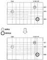
図7は、初期割当部112による位置情報の割当て例を示した説明図である。図7に示したように、デフォルメ地図上の地点P1、およびデフォルメ地図上の地点P1に対応する地点として通常地図上の地点P1’がユーザにより選択されると、初期割当部112は、通常地図上の地点P1’の位置情報(N35、E139)をデフォルメ地図上の地点P1に割当てる。 FIG. 7 is an explanatory diagram showing an example of location information allocation by the
また、デフォルメ地図上の地点P2、およびデフォルメ地図上の地点P2に対応する地点として通常地図上の地点P2’がユーザにより選択されると、初期割当部112は、通常地図上の地点P2’の位置情報(N37、E145)をデフォルメ地図上の地点P2に割当てる。 When the user selects a point P2 ′ on the normal map as a point P2 on the deformed map and a point P2 ′ on the normal map as a point corresponding to the point P2 on the deformed map, the initial assigning
同様に、デフォルメ地図上の地点P3、およびデフォルメ地図上の地点P3に対応する地点として通常地図上の地点P3’がユーザにより選択されると、初期割当部112は、通常地図上の地点P3’の位置情報(N30、E147)をデフォルメ地図上の地点P3に割当てる。 Similarly, when a point P3 ′ on the normal map is selected by the user as a point P3 on the deformed map and a point P3 ′ on the normal map as a point corresponding to the point P3 on the deformed map, the initial assigning
なお、上記では初期割当部112がデフォルメ地図上の3地点に位置情報を割り当てる例を説明したが、位置情報を割り当てる地点の数はかかる例に限定されない。初期割当部112は、デフォルメ地図上の少なくとも2地点に位置情報を割り当てればよく、例えば5地点、10地点など多数の地点に位置情報を割り当ててもよい。 Although the example in which the
また、上記では初期割当部112がユーザ操作に基づいてデフォルメ地図上の複数地点に位置情報を割り当てる例を説明したが、位置情報の割当て方法はかかる例に限定されない。例えば、初期割当部112は、デフォルメ地図上の地点と通常地図上の地点との対応関係を、デフォルメ地図と通常地図をマッチングすることにより検出し、デフォルメ地図上の地点に、通常地図上の対応地点に設定されている位置情報を割り当ててもよい。 In the above description, the example in which the
具体的には、初期割当部112は、デフォルメ地図上の道路と通常地図上の道路をマッチングすることにより、デフォルメ地図上の交差点に対応する通常地図上の交差点を検出してもよい。また、初期割当部112は、デフォルメ地図に記載されているPOI情報と通常地図上のPOI情報をマッチングすることにより、デフォルメ地図上のあるPOI情報が記載されている地点に対応する通常地図上の地点を検出してもよい。 Specifically, the
(位置情報補間部114)
位置情報補間部114は、初期割当部112により割当てられたデフォルメ地図上の複数地点の位置情報、およびデフォルメ地図上での複数地点の配置位置に基づき、デフォルメ地図上の各地点の位置情報を補間する。(Position information interpolation unit 114)
The position
より詳細には、位置情報補間部114は、複数地点から、基準点、および基準点と右方向(経度正方向)または左方向(経度負方向)に最も近接する第1の地点を選択する。そして、位置情報補間部114は、デフォルメ地図上の基準点および第1の地点の間の経度勾配が均一になるように基準点および第1の地点間の各地点の経度を補間する。なお、経度勾配は、経度方向の単位長さ当たりの経度変化量である。また、位置情報補間部114は、基準点に近接する地点を、デフォルメ地図上での配置位置に基づいて選択しても、初期割当部112により割り当てられた位置情報に基づいて選択してもよい。 More specifically, the position
同様に、位置情報補間部114は、複数地点から、基準点と上方向(緯度正方向)または下方向(緯度負方向)に最も近接する第2の地点を選択する。そして、位置情報補間部114は、デフォルメ地図上の基準点および第2の地点の間の緯度勾配が均一になるように基準点および第2の地点間の各地点の経度を補間する。なお、緯度勾配は、緯度方向の単位長さ当たりの緯度変化量である。 Similarly, the position
そして、位置情報補間部114は、複数地点のうちで基準点を順次に変更して上記の補間処理を繰り返す。以下、図8〜図11を参照し、位置情報補間部114による補間処理をより具体的に説明する。 And the position
図8〜図11は、位置情報補間部114による補間処理の具体例を示した説明図である。図8の上方に示したように、初期割当部112により地点P1〜P3の位置情報が割り当てられており、位置情報補間部114がまず地点P1を基準点として選択した場合を考える。 8 to 11 are explanatory diagrams showing specific examples of the interpolation processing by the position
この場合、位置情報補間部114は、地点P1と右方向に最も近接する地点P2を選択し、デフォルメ地図上の地点P1と地点P2の間の経度勾配が均一になるように、地点P1と地点P2の間の各地点の経度を補間する。ここで、地点P1と地点P2の間の経度勾配は、地点P1と地点P2の経度差「6度」を、デフォルメ地図における地点P1および地点P2間の経度方向上での距離(または画素数)で除算して得られる値であってもよい。 In this case, the position
これにより、図8の下方に示したように、地点P1と地点P2の間の1度間隔の経度線は、デフォルメ地図上の地点P1および地点P2間を均等に分割するものとなる。なお、位置情報補間部114は、デフォルメ地図上の各地点として、デフォルメ地図上の各画素、または複数画素からなる画素ブロックに対して位置情報を補間してもよい。 Thereby, as shown in the lower part of FIG. 8, the longitude lines at intervals of 1 degree between the points P <b> 1 and P <b> 2 equally divide between the points P <b> 1 and P <b> 2 on the deformed map. Note that the position
また、位置情報補間部114は、地点P1の左方向にも位置情報が割り当てられた地点が存在すればその地点を選択するが、図8に示した例では地点P1の左方向に位置情報が割り当てられた地点が存在しないので、地点P1の左方向に対する補間処理を行わない。 The position
続いて、位置情報補間部114は、図9に示したように、地点P1と上方向に最も近接する地点P2を選択し、デフォルメ地図上の地点P1と地点P2の間の緯度勾配が均一になるように、地点P1と地点P2の間の各地点の緯度を補間する。 Subsequently, as shown in FIG. 9, the position
ここで、地点P1と地点P2の間の緯度勾配は、地点P1と地点P2の緯度差「2度」を、デフォルメ地図における地点P1および地点P2間の緯度方向上での距離で除算して得られる値であってもよい。これにより、図9の下方に示したように、地点P1と地点P2の間の1度間隔の緯度線は、デフォルメ地図上の地点P1および地点P2間を均等に分割するものとなる。 Here, the latitude gradient between the points P1 and P2 is obtained by dividing the latitude difference “2 degrees” between the points P1 and P2 by the distance in the latitude direction between the points P1 and P2 on the deformed map. It may be a value. As a result, as shown in the lower part of FIG. 9, the latitude lines at intervals of 1 degree between the points P1 and P2 are equally divided between the points P1 and P2 on the deformed map.
さらに、位置情報補間部114は、図10に示したように、地点P1と下方向に最も近接する地点P3を選択し、デフォルメ地図上の地点P1と地点P3の間の緯度勾配が均一になるように、地点P1と地点P3の間の各地点の緯度を補間する。 Further, as shown in FIG. 10, the position
ここで、地点P1と地点P3の間の緯度勾配は、地点P1と地点P3の緯度差「5度」を、デフォルメ地図における地点P1および地点P3間の緯度方向上での距離で除算して得られる値であってもよい。これにより、図10の下方に示したように、地点P1と地点P3の間の1度間隔の緯度線は、デフォルメ地図上の地点P1および地点P3間を均等に分割するものとなる。 Here, the latitude gradient between the points P1 and P3 is obtained by dividing the latitude difference “5 degrees” between the points P1 and P3 by the distance in the latitude direction between the points P1 and P3 on the deformed map. It may be a value. Thereby, as shown in the lower part of FIG. 10, the latitude lines at intervals of 1 degree between the points P1 and P3 equally divide between the points P1 and P3 on the deformed map.
その後、位置情報補間部114は、図11に示したように基準点を地点P2に変更し、同様の補間処理を繰り返す。具体的には、位置情報補間部114は、地点P2と右方向に最も近接する地点P3を選択し、デフォルメ地図上の地点P2と地点P3の間の経度勾配が均一になるように、地点P2と地点P3の間の各地点の経度を補間する。 Thereafter, the position
ここで、地点P2と地点P3の間の経度勾配は、地点P2と地点P3の経度差「2度」を、デフォルメ地図における地点P1および地点P2間の経度方向上での距離(または画素数)で除算して得られる値であってもよい。これにより、図11の下方に示したように、地点P2と地点P3の間の1度間隔の経度線は、デフォルメ地図上の地点P2および地点P3間を均等に分割するものとなる。 Here, the longitude gradient between the point P2 and the point P3 indicates that the longitude difference “2 degrees” between the point P2 and the point P3 is the distance (or the number of pixels) in the longitude direction between the point P1 and the point P2 in the deformed map. It may be a value obtained by dividing by. Thereby, as shown in the lower part of FIG. 11, the longitude lines at intervals of 1 degree between the points P2 and P3 equally divide between the points P2 and P3 on the deformed map.
また、基準点である地点P2の左方向および下方向に対する補間処理は終了しており、地点P2の上方向には位置情報が割り当てられた地点が存在しないので、位置情報補間部114は、地点P2の左方向、下方向および上方向に対する補間処理を行わない。 In addition, since the interpolation processing for the left direction and the downward direction of the point P2, which is the reference point, has been completed and there is no point to which position information is assigned above the point P2, the position
その後、位置情報補間部114は、基準点を地点P3に変更するが、地点P3の左方向および上方向に対する補間処理は終了しており、地点P3の下方向および右方向には位置情報が割り当てられた地点が存在しないので、地点P3の全方向に対する補間処理を行わない。 Thereafter, the position
(補間後割当部116)
補間後割当部116は、位置情報補間部114による補間処理においてデフォルメ地図上で位置情報が補間されなかった範囲に、当該範囲の隣接範囲における補間結果に基づいて位置情報を割り当てる。以下、図12を参照し、補間後割当部116による位置情報の割当てについて具体的に説明する。(Post-interpolation allocation unit 116)
The
図12は、補間後割当部116による位置情報の割当ての具体例を示した説明図である。図12の上方に示したように、地点P1の左方向の範囲A、および地点P3の右方向の範囲Bは、経度未割り当て範囲である。 FIG. 12 is an explanatory diagram showing a specific example of allocation of position information by the
このため、補間後割当部116は、経度未割当て範囲Aに、隣接する地点P1および地点P2間の経度勾配に従って経度を割り当てる。これにより、図12の下方に示したように、経度未割当て範囲Aの1度間隔の経度線は、地点P1および地点P2間の1度間隔の経度線と同一間隔となる。 For this reason, the
同様に、補間後割当部116は、経度未割当て範囲Bに、隣接する地点P2および地点P3間の経度勾配に従って経度を割り当てる。これにより、図12の下方に示したように、経度未割当て範囲Bの1度間隔の経度線は、地点P2および地点P3間の1度間隔の経度線と同一間隔となる。 Similarly, the
また、図12の上方に示したように、地点P2の上方向の範囲C、および地点P3の下方向の範囲Dは、緯度未割り当て範囲である。このため、補間後割当部116は、緯度未割当て範囲Cに、隣接する地点P1および地点P2間の緯度勾配に従って緯度を割り当てる。これにより、図12の下方に示したように、緯度未割当て範囲Cの1度間隔の緯度線は、地点P1および地点P2間の1度間隔の緯度線と同一間隔となる。 Further, as shown in the upper part of FIG. 12, the upward range C of the point P2 and the downward range D of the point P3 are latitude unassigned ranges. For this reason, the
同様に、補間後割当部116は、緯度未割当て範囲Dに、隣接する地点P1および地点P3間の緯度勾配に従って緯度を割り当てる。これにより、図12の下方に示したように、緯度未割当て範囲Dの1度間隔の緯度線は、地点P1および地点P3間の1度間隔の緯度線と同一間隔となる。 Similarly, the
このように、位置情報補間部114により位置情報が補間されなかった範囲に補間後割当部116が位置情報を割り当てることにより、デフォルメ地図上の全域に位置情報を割り当てることができる。 As described above, the
(平滑化処理部118)
平滑化処理部118は、デフォルメ地図上で位置情報が割り当てられた隣接する範囲間の位置情報の勾配差を平滑化する。以下、図13を参照し、平滑化処理部118による勾配差の平滑化処理を具体的に説明する。(Smoothing processing unit 118)
The smoothing
図13は、平滑化処理部118による勾配差の平滑化処理の具体例を示した説明図である。図13の左方に示した例では、地点P2を境にして経度勾配が急激に変化する。しかし、実際のデフォルメ地図において、ある地点を境に急激に経度勾配(および緯度勾配)が変化することは少なく、経度勾配は徐々に変化するものと考えられる。 FIG. 13 is an explanatory diagram showing a specific example of the gradient difference smoothing processing by the smoothing
このため、平滑化処理部118は、図13の右方に示したように、地点P1および地点P2間で経度勾配を徐々に増加させることにより、地点1および地点2間と、地点2の右側の範囲との間での経度勾配差を平滑化する。これにより、デフォルメ地図上の各地点の位置情報を適正化することができる。 Therefore, the smoothing
なお、平滑化処理部118は、位置情報補間部114や補間後割当部116において行われた処理内容に基づいて勾配変化が急峻である箇所を検出しても、デフォルメ地図に割り当てられた位置情報に基づいて勾配変化が急峻である箇所を検出してもよい。 Even if the smoothing
(1−4.情報処理装置の動作)
以上、図6〜図13を参照して第1の実施形態による情報処理装置10の構成を説明した。続いて、図14を参照し、第1の実施形態による情報処理装置10の動作を説明する。(1-4. Operation of information processing apparatus)
The configuration of the
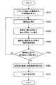
図14は、第1の実施形態による情報処理装置10の動作を示したフローチャートである。図14に示したように、まず、情報処理装置10の初期割当部112が、デフォルメ地図上の複数地点に位置情報を割り当てる(S410)。 FIG. 14 is a flowchart showing the operation of the
続いて、位置情報補間部114が、位置情報が割り当てられた複数地点から基準点を選択する(S420)。さらに、位置情報補間部114は、基準点と最も近接する地点を複数の地点から方向ごとに選択する(S430)。そして、位置情報補間部114は、基準点と選択地点との間の経度勾配または緯度勾配が均一になるように、デフォルメ地図上の基準点と選択地点との間の各地点に経度または緯度を補間する(S440)。 Subsequently, the position
そして、位置情報補間部114は、複数地点のうちで基準点を順次に変更し、複数地点全てを基準点として選択して補間処理を行う(S450)。 Then, the position
その後、補間後割当部116は、位置情報補間部114による補間処理においてデフォルメ地図上で位置情報が補間されなかった範囲に、当該範囲の隣接範囲における補間結果に基づいて位置情報を割り当てる(S460)。 After that, the
さらに、平滑化処理部118が、デフォルメ地図上で位置情報が割り当てられた隣接する範囲間の位置情報の勾配差を平滑化する(S470)。 Further, the smoothing
以上の処理により、情報処理装置10は、デフォルメ地図上の全域にわたり、適正な位置情報を割り当てることができる。したがって、PND20は、このデフォルメ地図を現在地表示やルート案内などのナビゲーションのために利用することが可能である。 With the above processing, the
<2.第2の実施形態>
以上説明したように、第1の実施形態によるPND20は、情報処理装置10により各地点に位置情報が割り当てられたデフォルメ地図を用いてナビゲーションを行う。これに対し、第2の実施形態によるPND21は、ナビゲーション機能に加え、デフォルメ地図上の各地点に位置情報を割り当てる機能を有する。以下、このような第2の実施形態によるPND21の構成を説明する。<2. Second Embodiment>
As described above, the
図15は、第2の実施形態によるPND21の構成を示した説明図である。図15に示したように、第2の実施形態によるPND21は、表示部22、操作部204、記憶部208およびナビゲーション機能ユニット210に加え、位置情報割当てユニット110を備える。 FIG. 15 is an explanatory diagram showing the configuration of the
このため、第2の実施形態によるPND21は、ナビゲーション機能ユニット210によりナビゲーションを行うことも、位置情報割当てユニット110によりデフォルメ地図上の各地点に位置情報を割り当てることもできる。なお、ナビゲーション機能ユニット210、および位置情報割当てユニット110については第1の実施形態において説明したので、詳細な説明を省略する。 Therefore, the
<3.第3の実施形態>
第1の実施形態および第2の実施形態において説明したPND20、21はナビゲーション装置の一例に過ぎず、ナビゲーション装置はかかる例に限定されない。例えば、ナビゲーション装置は、以下に第3の実施形態として説明する携帯電話30であってもよい。その他、詳細な説明は省略するが、ナビゲーション装置は、PHS、携帯用音楽再生装置、携帯用映像処理装置、携帯用ゲーム機器、および携帯型の撮像装置などであってもよい。<3. Third Embodiment>
The
図16は、第3の実施形態による携帯電話30の外観図である。図16に示したように、第3の実施形態による携帯電話30は、表示部302と、クレードル303と、操作部304と、吸盤306と、マイクロホン314と、スピーカ324と、を備える。 FIG. 16 is an external view of a
クレードル303は、第1の実施形態によるPND20と同様に、車両のダッシュボード上に吸盤306を介して取り付けられ、かつ、携帯電話30と機械的および電気的に接続される。このため、携帯電話30は、クレードル303を介して車両から供給される電力に基づいて動作することが可能である。なお、携帯電話30はバッテリを内蔵しており、クレードル303から取り外された場合にはバッテリから供給される電力に基づいて動作することができる。 Like the
図17は、第3の実施形態による携帯電話30の構成を示した機能ブロック図である。図17に示したように、第3の実施形態による携帯電話30は、ナビゲーション機能ユニット210と、表示部302と、操作部304と、記憶部308と、携帯電話機能ユニット310と、総括制御部334と、を備える。 FIG. 17 is a functional block diagram showing the configuration of the
また、携帯電話機能ユニット310は、通話機能や電子メール機能などを実現するための構成であり、通信アンテナ312と、マイクロホン314と、エンコーダ316と、送受信部320と、スピーカ324と、デコーダ326と、携帯電話制御部330と、を備える。なお、ナビゲーション機能ユニット210については第1の実施形態で説明したので、詳細な説明を省略する。 The mobile
マイクロホン314は、音声を集音し、音声信号として出力する。エンコーダ316は、携帯電話制御部330による制御に従い、マイクロホン314から入力される音声信号のデジタル変換およびエンコードなどを行い、音声データを送受信部320に出力する。 The
送受信部320は、エンコーダ316から入力される音声データを所定の方式に従って変調し、通信アンテナ312から無線で携帯電話30の基地局へ送信する。また、送受信部320は、通信アンテナ312により無線信号を復調して音声データを取得し、デコーダ326に出力する。 The transmission /
デコーダ326は、携帯電話制御部330による制御に従い、送受信部320から入力される音声データのデコードおよびアナログ変換などを行い、音声信号をスピーカ324に出力する。スピーカ324は、デコーダ326から供給される音声信号に基づいて音声を出力する。 The
また、携帯電話制御部330は、電子メールを受信する場合、送受信部320からデコーダ326に受信データを供給し、デコーダ326に受信データをデコードさせる。そして、携帯電話制御部330は、デコードにより得られた電子メールデータを表示部302に出力して表示部302に表示させる共に、記憶部308に電子メールデータを記録する。 Further, when receiving the electronic mail, the mobile
また、携帯電話制御部330は、電子メールを送信する場合、操作部304を介して入力された電子メールデータをエンコーダ316にエンコードさせ、送受信部320および通信アンテナ312を介して無線送信する。 In addition, when transmitting an e-mail, the mobile
総括制御部334は、上述した携帯電話ユニット310およびナビゲーション機能ユニット210を制御する。例えば、総括制御部334は、ナビゲーション機能ユニット210によりナビゲーション機能を実行している間に電話がかかってきた場合、ナビゲーション機能を携帯電話ユニット310による通話機能に一時的に切替え、通話終了後、ナビゲーション機能ユニット210にナビゲーション機能を再開させてもよい。 The
<4.まとめ>
以上説明したように、本発明の実施形態においては、初期割当部112がデフォルメ地図上の複数地点に位置情報を割当てる。また、位置情報補間部114が、初期割当部112により割当てられたデフォルメ地図上の複数地点の位置情報、およびデフォルメ地図上での複数地点の配置位置に基づき、デフォルメ地図上の各地点の位置情報を補間する。<4. Summary>
As described above, in the embodiment of the present invention, the
また、本発明の実施形態においては、補間後処理部116が、位置情報補間部114による補間処理においてデフォルメ地図上で位置情報が補間されなかった範囲に、当該範囲の隣接範囲における補間結果に基づいて位置情報を割り当てる。これにより、デフォルメ地図上の全域に位置情報を割り当てることができる。 Further, in the embodiment of the present invention, the
さらに、本発明の実施形態においては、平滑化処理部118が、デフォルメ地図上で位置情報が割り当てられた隣接する範囲間の位置情報の勾配差を平滑化する。デフォルメ地図上の各地点の位置情報を適正化することができる。 Furthermore, in the embodiment of the present invention, the smoothing
なお、添付図面を参照しながら本発明の好適な実施形態について詳細に説明したが、本発明はかかる例に限定されない。本発明の属する技術の分野における通常の知識を有する者であれば、特許請求の範囲に記載された技術的思想の範疇内において、各種の変更例または修正例に想到し得ることは明らかであり、これらについても、当然に本発明の技術的範囲に属するものと了解される。 Although the preferred embodiments of the present invention have been described in detail with reference to the accompanying drawings, the present invention is not limited to such examples. It is obvious that a person having ordinary knowledge in the technical field to which the present invention pertains can come up with various changes or modifications within the scope of the technical idea described in the claims. Of course, it is understood that these also belong to the technical scope of the present invention.
例えば、本明細書の情報処理装置10の処理における各ステップは、必ずしもフローチャートとして記載された順序に沿って時系列に処理する必要はない。例えば、情報処理装置10の処理における各ステップは、フローチャートとして記載した順序と異なる順序で処理されても、並列的に処理されてもよい。 For example, each step in the processing of the
また、PND20、PND21および携帯電話30などのナビゲーション装置や情報処理装置10に内蔵されるCPU、ROMおよびRAMなどのハードウェアを、上述しナビゲーション装置や情報処理装置10の各構成と同等の機能を発揮させるためのコンピュータプログラムも作成可能である。また、該コンピュータプログラムを記憶させた記憶媒体も提供される。 Further, hardware such as a CPU, ROM, and RAM incorporated in the navigation device such as the
10 情報処理装置
20、21 PND
22、102、302 表示部
30 携帯電話
104、204、304 操作部
108、208、308 記憶部
24、303 クレードル
110 位置情報割当てユニット
112 初期割当部
114 位置情報補間部
116 補間後割当部
118 平滑化処理部
210 ナビゲーション機能ユニット
212 GPSアンテナ
214 GPS処理部
216 ナビゲーション部
220 3軸加速度センサ
222 Y軸ジャイロセンサ
224 速度算出部
230 Z軸ジャイロセンサ
232 角度算出部
240 位置算出部
250 気圧センサ
252 高度算出部
310 携帯電話機能ユニット
312 通信アンテナ
314 マイクロホン
316 エンコーダ
320 送受信部
326 デコーダ
324 スピーカ
330 携帯電話制御部
334 統括制御部
10
22, 102, 302
Claims (11)
Translated fromJapanese前記複数地点に割当てられた位置情報、および前記デフォルメ地図上での前記複数地点の配置位置に基づき、前記デフォルメ地図上の各地点の位置情報を補間する補間部と;
を備える、情報処理装置。A location information allocation unit that allocates location information to a plurality of points on the deformed map;
An interpolation unit that interpolates position information of each point on the deformed map based on position information assigned to the plurality of points and an arrangement position of the plurality of points on the deformed map;
An information processing apparatus comprising:
前記複数地点のうちの基準点、および前記複数地点のうちの第1の地点との経度差に基づき、前記デフォルメ地図上の前記基準点および前記第1の地点間の各地点の経度を補間し、
前記基準点、および前記複数地点のうちの第2の地点との緯度差に基づき、前記デフォルメ地図上の前記基準点および前記第2の地点間の各地点の緯度を補間する、請求項1に記載の情報処理装置。The interpolation unit
Based on the longitude difference between the reference point of the plurality of points and the first point of the plurality of points, the longitude of each point between the reference point on the deformed map and the first point is interpolated. ,
The latitude of each point between the reference point and the second point on the deformed map is interpolated based on a latitude difference between the reference point and a second point among the plurality of points. The information processing apparatus described.
前記デフォルメ地図上の前記基準点および前記第1の地点の間の経度勾配が均一になるように前記基準点および前記第1の地点間の各地点の経度を補間し、
前記デフォルメ地図上の前記基準点および前記第2の地点の間の緯度勾配が均一になるように前記基準点および前記第2の地点間の各地点の緯度を補間する、請求項2に記載の情報処理装置。The interpolation unit
Interpolating the longitude of each point between the reference point and the first point so that the longitude gradient between the reference point and the first point on the deformed map is uniform,
The latitude of each point between the reference point and the second point is interpolated so that a latitude gradient between the reference point and the second point on the deformed map is uniform. Information processing device.
前記第2の地点は、前記基準点と緯度の正方向上または負方向上で最も近接する地点である、請求項3に記載の情報処理装置。The first point is a point closest to the reference point on the positive or negative direction of longitude,
The information processing apparatus according to claim 3, wherein the second point is a point closest to the reference point on a positive or negative direction of latitude.
デフォルメ地図上の複数地点に位置情報を割り当てる位置情報割当部と;
前記複数地点に割当てられた位置情報、および前記デフォルメ地図上での前記複数地点の配置位置に基づき、前記デフォルメ地図上の各地点の位置情報を補間する補間部と;
として機能させるための、プログラム。Computer
A location information allocation unit that allocates location information to a plurality of points on the deformed map;
An interpolation unit that interpolates position information of each point on the deformed map based on position information assigned to the plurality of points and an arrangement position of the plurality of points on the deformed map;
Program to function as
前記複数地点に割当てられた位置情報、および前記デフォルメ地図上での前記複数地点の配置位置に基づき、前記デフォルメ地図上の各地点の位置情報を補間するステップと;
を含む、情報処理方法。Assigning location information to multiple points on the deformed map;
Interpolating position information of each point on the deformed map based on position information assigned to the plurality of points and an arrangement position of the plurality of points on the deformed map;
Including an information processing method.
デフォルメ地図上の複数地点に位置情報を割り当てられ、
前記複数地点に割当てられた位置情報、および前記デフォルメ地図上での前記複数地点の配置位置に基づき、前記デフォルメ地図上の各地点の位置情報が補間された、デフォルメ地図の地図データ。
By computer
Location information can be assigned to multiple points on the deformed map,
Map data of a deformed map obtained by interpolating position information of each point on the deformed map based on position information assigned to the plurality of points and an arrangement position of the plurality of points on the deformed map.
Priority Applications (3)
| Application Number | Priority Date | Filing Date | Title |
|---|---|---|---|
| JP2009298148AJP2011138011A (en) | 2009-12-28 | 2009-12-28 | Information processing apparatus, program, information processing method, and map data |
| US12/948,096US8868336B2 (en) | 2009-12-28 | 2010-11-17 | Information processing apparatus, program, information processing method, and map data |
| CN201010591739.6ACN102147993B (en) | 2009-12-28 | 2010-12-16 | Information processing apparatus, program, information processing method, and map data |
Applications Claiming Priority (1)
| Application Number | Priority Date | Filing Date | Title |
|---|---|---|---|
| JP2009298148AJP2011138011A (en) | 2009-12-28 | 2009-12-28 | Information processing apparatus, program, information processing method, and map data |
Publications (1)
| Publication Number | Publication Date |
|---|---|
| JP2011138011Atrue JP2011138011A (en) | 2011-07-14 |
Family
ID=44188529
Family Applications (1)
| Application Number | Title | Priority Date | Filing Date |
|---|---|---|---|
| JP2009298148APendingJP2011138011A (en) | 2009-12-28 | 2009-12-28 | Information processing apparatus, program, information processing method, and map data |
Country Status (3)
| Country | Link |
|---|---|
| US (1) | US8868336B2 (en) |
| JP (1) | JP2011138011A (en) |
| CN (1) | CN102147993B (en) |
Cited By (5)
| Publication number | Priority date | Publication date | Assignee | Title |
|---|---|---|---|---|
| JP2012198310A (en)* | 2011-03-18 | 2012-10-18 | Mitsubishi Electric Corp | Map element arrangement device and map element arrangement method |
| JP2015072131A (en)* | 2013-10-01 | 2015-04-16 | 株式会社ナビタイムジャパン | Information processing system, server, terminal device, information processing device, information processing method, and information processing program |
| JP2016061621A (en)* | 2014-09-17 | 2016-04-25 | 株式会社インテック | Navigation device, navigation method and navigation program |
| JP2023102806A (en)* | 2022-01-13 | 2023-07-26 | アルプスアルパイン株式会社 | Map processing system |
| JP7752915B2 (en) | 2022-01-13 | 2025-10-14 | アルプスアルパイン株式会社 | Map Processing System |
Families Citing this family (6)
| Publication number | Priority date | Publication date | Assignee | Title |
|---|---|---|---|---|
| US20130106990A1 (en) | 2011-11-01 | 2013-05-02 | Microsoft Corporation | Planar panorama imagery generation |
| KR20130066354A (en)* | 2011-12-12 | 2013-06-20 | 현대엠엔소프트 주식회사 | Apparatus and method fot map matching of user termanal |
| US10008021B2 (en) | 2011-12-14 | 2018-06-26 | Microsoft Technology Licensing, Llc | Parallax compensation |
| US9406153B2 (en)* | 2011-12-14 | 2016-08-02 | Microsoft Technology Licensing, Llc | Point of interest (POI) data positioning in image |
| JP5959341B2 (en)* | 2012-07-04 | 2016-08-02 | アルパイン株式会社 | Electronic device, search target candidate name display method and program thereof |
| WO2016104181A1 (en)* | 2014-12-26 | 2016-06-30 | シャープ株式会社 | Information processing device, portable terminal, method for controlling information processing device, and program |
Citations (3)
| Publication number | Priority date | Publication date | Assignee | Title |
|---|---|---|---|---|
| JP2008102079A (en)* | 2006-10-20 | 2008-05-01 | Genetec Corp | Navigation system |
| JP2008191075A (en)* | 2007-02-07 | 2008-08-21 | Alps Sha:Kk | Deformation map position specifying method, deformed map position specifying system, measurement map position specifying method, and measurement map position specifying system |
| JP2008281349A (en)* | 2007-05-08 | 2008-11-20 | Nomura Research Institute Ltd | Simple map display control apparatus and method |
Family Cites Families (16)
| Publication number | Priority date | Publication date | Assignee | Title |
|---|---|---|---|---|
| JPH10288944A (en)* | 1997-04-16 | 1998-10-27 | Nof Corp | Method and device for converting map image |
| JP4240446B2 (en)* | 2002-06-24 | 2009-03-18 | 富士通テン株式会社 | Image display device |
| CA2480493A1 (en)* | 2002-03-29 | 2003-10-23 | Matsushita Electric Industrial Co., Ltd. | Map matching method, map matching device, database for shape matching, and shape matching device |
| US7565155B2 (en)* | 2002-04-10 | 2009-07-21 | Networks In Motion | Method and system for dynamic estimation and predictive route generation |
| US7383125B2 (en)* | 2005-05-16 | 2008-06-03 | Alpine Electronics, Inc. | Navigation method and system for accurately estimating positions of street address numbers |
| US20070185649A1 (en)* | 2006-02-08 | 2007-08-09 | Tele Atlas North America, Inc. | Map database having address points for determining destinations |
| US8290705B2 (en)* | 2007-04-25 | 2012-10-16 | Rio Sisa Idea Farm | Mobile navigation system with graphic crime-risk display |
| US10107628B2 (en)* | 2007-08-11 | 2018-10-23 | Infogation Corporation | Method and apparatus for navigating on artistic maps |
| JP5478008B2 (en) | 2007-10-29 | 2014-04-23 | 三菱電機株式会社 | Deformation map generator |
| US20090177382A1 (en)* | 2008-01-03 | 2009-07-09 | Commscope, Inc. Of North Carolina | Calibration of a Navigation System |
| US8490025B2 (en)* | 2008-02-01 | 2013-07-16 | Gabriel Jakobson | Displaying content associated with electronic mapping systems |
| US20100268460A1 (en)* | 2009-04-15 | 2010-10-21 | Telenav, Inc. | Navigation system with predictive multi-routing and method of operation thereof |
| US8896686B2 (en)* | 2009-06-23 | 2014-11-25 | Here Global B.V. | Determining a geometric parameter from a single image |
| US9710961B2 (en)* | 2009-09-17 | 2017-07-18 | Nokia Technologies Oy | Method and apparatus for providing contextual rendering of a map |
| US20110087425A1 (en)* | 2009-10-08 | 2011-04-14 | Telenav, Inc. | Navigation system with map compression and method of operation thereof |
| US8566020B2 (en)* | 2009-12-01 | 2013-10-22 | Nokia Corporation | Method and apparatus for transforming three-dimensional map objects to present navigation information |
- 2009
- 2009-12-28JPJP2009298148Apatent/JP2011138011A/enactivePending
- 2010
- 2010-11-17USUS12/948,096patent/US8868336B2/enactiveActive
- 2010-12-16CNCN201010591739.6Apatent/CN102147993B/ennot_activeExpired - Fee Related
Patent Citations (3)
| Publication number | Priority date | Publication date | Assignee | Title |
|---|---|---|---|---|
| JP2008102079A (en)* | 2006-10-20 | 2008-05-01 | Genetec Corp | Navigation system |
| JP2008191075A (en)* | 2007-02-07 | 2008-08-21 | Alps Sha:Kk | Deformation map position specifying method, deformed map position specifying system, measurement map position specifying method, and measurement map position specifying system |
| JP2008281349A (en)* | 2007-05-08 | 2008-11-20 | Nomura Research Institute Ltd | Simple map display control apparatus and method |
Cited By (5)
| Publication number | Priority date | Publication date | Assignee | Title |
|---|---|---|---|---|
| JP2012198310A (en)* | 2011-03-18 | 2012-10-18 | Mitsubishi Electric Corp | Map element arrangement device and map element arrangement method |
| JP2015072131A (en)* | 2013-10-01 | 2015-04-16 | 株式会社ナビタイムジャパン | Information processing system, server, terminal device, information processing device, information processing method, and information processing program |
| JP2016061621A (en)* | 2014-09-17 | 2016-04-25 | 株式会社インテック | Navigation device, navigation method and navigation program |
| JP2023102806A (en)* | 2022-01-13 | 2023-07-26 | アルプスアルパイン株式会社 | Map processing system |
| JP7752915B2 (en) | 2022-01-13 | 2025-10-14 | アルプスアルパイン株式会社 | Map Processing System |
Also Published As
| Publication number | Publication date |
|---|---|
| CN102147993A (en) | 2011-08-10 |
| US8868336B2 (en) | 2014-10-21 |
| US20110161007A1 (en) | 2011-06-30 |
| CN102147993B (en) | 2014-07-23 |
Similar Documents
| Publication | Publication Date | Title |
|---|---|---|
| JP2011138011A (en) | Information processing apparatus, program, information processing method, and map data | |
| JP5985788B2 (en) | Information processing device | |
| JP5648447B2 (en) | Tour route generating device, tour route generating method, and program | |
| US8849564B2 (en) | Route comparison device, route comparison method, and program | |
| JP2011174744A (en) | Navigation device, navigation method and program | |
| JP5998777B2 (en) | Information processing apparatus, information processing method, program, and information processing system | |
| CN105594267B (en) | The virtual crumbs searched for indoor location road | |
| JP5267618B2 (en) | Information processing device | |
| JP4632793B2 (en) | Portable terminal with navigation function | |
| US9361858B2 (en) | Position information providing device, position information providing method, position information providing system, and program | |
| US9268474B2 (en) | Information processing apparatus, method, and non-transitory computer-readable medium to control display of a map | |
| JP2011141131A (en) | Navigation apparatus, navigation method, and program | |
| JP2007058093A (en) | MAP DISPLAY DEVICE, MAP DISPLAY METHOD, MAP DISPLAY PROGRAM, AND RECORDING MEDIUM CONTAINING THE PROGRAM | |
| JP2011149778A (en) | Navigation system, navigation method and program | |
| JP2009053149A (en) | Map information generating device, navigation device, map information generating method and map image display device | |
| JP5366170B2 (en) | Map display device | |
| JP2012189368A (en) | Terminal device, method for changing map display, and program |
Legal Events
| Date | Code | Title | Description |
|---|---|---|---|
| A621 | Written request for application examination | Free format text:JAPANESE INTERMEDIATE CODE: A621 Effective date:20121106 | |
| A977 | Report on retrieval | Free format text:JAPANESE INTERMEDIATE CODE: A971007 Effective date:20131203 | |
| A131 | Notification of reasons for refusal | Free format text:JAPANESE INTERMEDIATE CODE: A131 Effective date:20140212 | |
| A521 | Request for written amendment filed | Free format text:JAPANESE INTERMEDIATE CODE: A523 Effective date:20140320 | |
| A02 | Decision of refusal | Free format text:JAPANESE INTERMEDIATE CODE: A02 Effective date:20140408 |