Movatterモバイル変換


[0]ホーム

URL:


JP2011133712A - Electronic signboard and cooling control method for the same - Google Patents

Electronic signboard and cooling control method for the same
Download PDF

Info

Publication number
JP2011133712A
JP2011133712AJP2009293895AJP2009293895AJP2011133712AJP 2011133712 AJP2011133712 AJP 2011133712AJP 2009293895 AJP2009293895 AJP 2009293895AJP 2009293895 AJP2009293895 AJP 2009293895AJP 2011133712 AJP2011133712 AJP 2011133712A
Authority
JP
Japan
Prior art keywords
temperature
evaporator
compressor
fan
liquid crystal
Prior art date
Legal status (The legal status is an assumption and is not a legal conclusion. Google has not performed a legal analysis and makes no representation as to the accuracy of the status listed.)
Pending
Application number
JP2009293895A
Other languages
Japanese (ja)
Inventor
Satoru Imai
悟 今井
Yoshihiro Kurokawa
喜寛 黒川
Toshikazu Ishihara
寿和 石原
Fumihiko Kurita
文彦 栗田
Masaya Nakamichi
雅哉 中道
Current Assignee (The listed assignees may be inaccurate. Google has not performed a legal analysis and makes no representation or warranty as to the accuracy of the list.)
Sanyo Electric Co Ltd
Original Assignee
Sanyo Electric Co Ltd
Priority date (The priority date is an assumption and is not a legal conclusion. Google has not performed a legal analysis and makes no representation as to the accuracy of the date listed.)
Filing date
Publication date
Application filed by Sanyo Electric Co LtdfiledCriticalSanyo Electric Co Ltd
Priority to JP2009293895ApriorityCriticalpatent/JP2011133712A/en
Publication of JP2011133712ApublicationCriticalpatent/JP2011133712A/en
Pendinglegal-statusCriticalCurrent

Links

Images

Landscapes

Abstract

<P>PROBLEM TO BE SOLVED: To provide an electronic signboard capable of preventing the occurrence of dew condensation in a casing by controlling a temperature distribution in the casing in which a liquid crystal display is sealed; and to provide a cooling control method for the same. <P>SOLUTION: The electronic signboard 1 includes: a glass plate 12 which is provided to a position facing the display surface 11 of a liquid crystal display 10 in a casing 8 housing the liquid crystal display 10; a gap between the display surface 11 and the glass plate 12; an evaporator 42 disposed in the casing 8; a circulation fan 50 for guiding air cooled by the evaporator 42 to the gap and then returning the air to the evaporator 42; a freezing cycle 40 having a compressor 44, a condenser 46, and an expansion valve 48 disposed below the liquid crystal display 10. The electronic signboard 1 also includes a temperature sensor 36F for detecting the cooling temperature of the liquid crystal display 10, and a controller 35 for controlling rotation of the circulation fan 50 and a heat discharge fan 51 according to the detected temperature. <P>COPYRIGHT: (C)2011,JPO&INPIT

Description

Translated fromJapanese

本発明は、液晶ディスプレイ等のフラットパネルディスプレイに広告を表示する電子看板に係り、特に、当該フラットパネルディスプレイの冷却に伴う結露による視認性の悪化を防止する技術に関する。  The present invention relates to an electronic signboard that displays an advertisement on a flat panel display such as a liquid crystal display, and more particularly to a technique for preventing deterioration in visibility due to condensation accompanying cooling of the flat panel display.

液晶ディスプレイを備え、この液晶ディスプレイに映像や文字等の広告情報を表示する電子看板(「デジタルサイネージ」とも称される)が知られている。また、電子看板を街頭等の屋外で使用可能にすべく、液晶ディスプレイを筐体に密閉して風雨やダストから保護したものが知られている。このように液晶ディスプレイを筐体に密閉した場合には、筐体の内部から外部へ熱が逃げなくなるため、液晶ディスプレイを自然空冷することができなくなる。そこで従来では、液晶ディスプレイを空冷する空冷手段を筐体に内蔵し、液晶ディスプレイを強制空冷している(例えば、特許文献1参照)。  An electronic signboard (also referred to as “digital signage”) that includes a liquid crystal display and displays advertisement information such as images and characters on the liquid crystal display is known. In addition, in order to make it possible to use an electronic signboard outdoors on a street or the like, a liquid crystal display sealed in a casing and protected from wind and rain and dust is known. When the liquid crystal display is sealed in the casing in this way, heat does not escape from the inside of the casing to the outside, and the liquid crystal display cannot be naturally cooled. Therefore, conventionally, an air cooling means for air-cooling the liquid crystal display is built in the casing, and the liquid crystal display is forcibly air-cooled (see, for example, Patent Document 1).

特開2006−308726号公報JP 2006-308726 A

ところで、上記従来の電子看板においては、筐体内における温度分布状態によって、筐体内に結露が発生することがあり、特に、液晶ディスプレイの表示面に重なる位置に結露が発生すると、表示の視認性が低下するという問題があった。
本発明は、上述した事情に鑑みてなされたものであり、液晶ディスプレイを密閉した筐体内の温度分布を制御することにより、筐体内における結露の発生を防止できる電子看板、及び、電子看板における冷却制御方法を提供することを目的とする。
By the way, in the above-mentioned conventional electronic signboard, dew condensation may occur in the case depending on the temperature distribution state in the case. In particular, if dew condensation occurs at a position overlapping the display surface of the liquid crystal display, the visibility of the display is improved. There was a problem of lowering.
The present invention has been made in view of the above-described circumstances, and an electronic signboard that can prevent the occurrence of condensation in the casing by controlling the temperature distribution in the casing in which the liquid crystal display is sealed, and cooling in the electronic signboard An object is to provide a control method.

上記目的を達成するために、本発明は、平面型ディスプレイを筐体に納め、前記筐体内部に、前記平面型ディスプレイの表示面と対向する位置に透明板を設け、前記表示面と前記透明板の間に隙間を設け、前記筐体内部に蒸発器を設け、前記蒸発器で冷やされた空気を前記隙間に導いた後前記蒸発器へ戻す循環用ファンを設け、前記蒸発器に連結されて、前記平面型ディスプレイの下方に備えられた圧縮機と、凝縮器と、膨張手段とを有する冷凍サイクルを設けた電子看板において、前記筐体内部に備えられた前記平面型ディスプレイの冷却温度を検出する温度センサと、前記温度センサにより検出された温度に応じて、前記圧縮機の動作中に前記循環用ファンの回転とともに前記凝縮器の放熱用ファンの回転を制御する制御部と、を備えたことを特徴とする。  In order to achieve the above object, the present invention provides a flat display housed in a housing, a transparent plate is provided in the housing at a position facing the display surface of the flat display, and the display surface and the transparent A gap is provided between the plates, an evaporator is provided inside the casing, an air cooled by the evaporator is guided to the gap, and then a circulation fan is returned to the evaporator, connected to the evaporator, In an electronic signboard provided with a refrigeration cycle having a compressor, a condenser, and an expansion means provided below the flat display, a cooling temperature of the flat display provided in the housing is detected. A temperature sensor; and a controller that controls rotation of the heat dissipation fan of the condenser along with rotation of the circulation fan during operation of the compressor according to a temperature detected by the temperature sensor. And wherein the door.

また、本発明は、上記の電子看板において、前記平面型ディスプレイは、前記筐体の密封空間内に配置され、前記密封空間は、前記筐体と前記透明板で形成され、前記密封空間内に前記蒸発器と前記循環用ファンが設けられていることを特徴とする。  Further, the present invention is the above electronic signboard, wherein the flat display is disposed in a sealed space of the casing, and the sealed space is formed by the casing and the transparent plate, The evaporator and the circulation fan are provided.

また、本発明は、上記の電子看板において、前記制御部は、前記圧縮機の吸込冷媒の温度と前記蒸発器における蒸発温度との温度差が予め設定された値を超えるように前記循環用ファンと前記放熱用ファンとを制御することを特徴とする。  Further, the present invention is the above electronic signboard, wherein the control unit is configured so that the temperature difference between the temperature of the suction refrigerant of the compressor and the evaporation temperature of the evaporator exceeds a preset value. And the heat dissipating fan are controlled.

また、本発明は、上記の電子看板において、前記制御部は、前記圧縮機の吸込冷媒の温度と前記蒸発器における蒸発温度との温度差が予め設定された値を超え、かつ、前記圧縮機のケース温度または前記圧縮機の吐出温度が所定温度を超えないように、前記循環用ファンと前記放熱用ファンとの回転数を制御することを特徴とする。  Further, the present invention provides the electronic sign as described above, wherein the control unit has a temperature difference between a temperature of the suction refrigerant of the compressor and an evaporation temperature of the evaporator exceeding a preset value, and the compressor The number of rotations of the circulation fan and the heat dissipating fan is controlled so that the case temperature or the discharge temperature of the compressor does not exceed a predetermined temperature.

また、本発明は、前記密封空間において結露の可能性がある所定位置に第2の温度センサを設け、前記制御部は、前記圧縮機の動作中に前記循環用ファンと前記凝縮器の放熱用ファンとの回転を制御し、前記第2の温度センサにより検出された温度が予め設定された温度より高くなった場合には、前記圧縮機及び前記放熱用ファンを停止させることを特徴とすることを特徴とする。  In the present invention, a second temperature sensor is provided at a predetermined position where condensation may occur in the sealed space, and the controller is configured to radiate heat from the circulation fan and the condenser during operation of the compressor. The rotation with the fan is controlled, and the compressor and the heat dissipating fan are stopped when the temperature detected by the second temperature sensor is higher than a preset temperature. It is characterized by.

また、上記目的を達成するために、本発明は、平面型ディスプレイを筐体に納め、前記筐体内部に、前記平面型ディスプレイの表示面と対向する位置に透明板を設け、前記表示面と前記透明板の間に隙間を設け、前記筐体内部に蒸発器を設け、前記蒸発器で冷やされた空気を前記隙間に導いた後前記蒸発器へ戻す循環用ファンを設け、前記蒸発器に連結されて、前記平面型ディスプレイの下方に備えられた圧縮機と、凝縮器と、膨張手段とを有する冷凍サイクルと、前記冷凍サイクルを制御する制御部とを設けた電子看板における冷却制御方法であって、前記制御部により、温度センサにより前記筐体内部に備えられた前記平面型ディスプレイの冷却温度を検出し、検出された温度に応じて、前記圧縮機の動作中に前記循環用ファンの回転とともに前記凝縮器の放熱用ファンの回転を制御すること、を備えたことを特徴とする。  In order to achieve the above object, the present invention includes a flat display in a housing, a transparent plate is provided in the housing at a position facing the display surface of the flat display, and the display surface. A gap is provided between the transparent plates, an evaporator is provided inside the housing, a circulation fan is provided to return air cooled by the evaporator to the gap and then returned to the evaporator, and is connected to the evaporator. And a cooling control method for an electronic signboard provided with a refrigeration cycle having a compressor, a condenser, and expansion means provided below the flat display, and a control unit for controlling the refrigeration cycle. The controller detects a cooling temperature of the flat display provided in the housing by a temperature sensor, and rotates the circulation fan during the operation of the compressor according to the detected temperature. Wherein controlling the rotation of the radiating fan of the condenser it is also characterized by comprising a.

本発明によれば、筐体内部に納められた平面型ディスプレイを冷凍サイクルにより冷却する構成において、平面型ディスプレイの冷却温度に応じて、圧縮機の動作中に制御部によって循環用ファンと凝縮器の放熱用ファンの回転を制御することで、平面型ディスプレイを収めた筐体内における結露を防止できる。  According to the present invention, in the configuration in which the flat display housed in the housing is cooled by the refrigeration cycle, the circulation fan and the condenser are operated by the control unit during the operation of the compressor according to the cooling temperature of the flat display. By controlling the rotation of the heat dissipating fan, it is possible to prevent condensation in the housing containing the flat display.

本発明の実施形態に係る電子看板の外観構成を示す斜視図である。It is a perspective view which shows the external appearance structure of the electronic signboard which concerns on embodiment of this invention.電子看板の縦断面を、一部を省略して示す図である。It is a figure which abbreviate | omits and shows the longitudinal cross-section of an electronic signboard.看板本体の横断面図である。It is a cross-sectional view of a signboard body.循環流路と液晶ディスプレイとを示す模式図である。It is a schematic diagram which shows a circulation channel and a liquid crystal display.電子看板に設けられた冷凍サイクルの構成を詳細に示す図である。It is a figure which shows the structure of the refrigerating cycle provided in the electronic signboard in detail.冷凍サイクルの制御を示すフローチャートである。It is a flowchart which shows control of a refrigerating cycle.冷凍サイクルの制御を詳細に示すフローチャートである。It is a flowchart which shows the control of a refrigerating cycle in detail.

以下、図面を参照して本発明の一実施形態について説明する。
図1に示すように、電子看板1は、扁平な直方体状の外観を呈した看板本体2と、この看板本体2を支持する土台4と、看板本体2の内部を冷却する冷却ユニット6とを備えている。
Hereinafter, an embodiment of the present invention will be described with reference to the drawings.
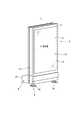
As shown in FIG. 1, anelectronic signboard 1 includes asignboard body 2 that has a flat rectangular parallelepiped appearance, abase 4 that supports thesignboard body 2, and acooling unit 6 that cools the inside of thesignboard body 2. I have.

看板本体2は、高さが2メートル、幅が1メートル程度の縦長の扁平な直方体状の筐体8を有し、その内部に液晶ディスプレイ10が表示面11を正面に向けて納められている。この表示面11に対向する筐体8の正面は大きく開口し、その開口には内部を視認可能に透明な硬質のガラス板12(透明板)が嵌め込まれており、このガラス板12を通じて表示面11の全体を視認可能に構成されている。この表示面11には、各種映像や文字情報が表示され可変表示型の広告媒体として用いられる。また、看板本体2は、ガラス板12と筐体8の間にパッキンが配置されるなど密封構造を成し、街頭等の屋外での使用に耐える構造とされている。  Thesignboard body 2 has a vertically long flat rectangularparallelepiped housing 8 having a height of about 2 meters and a width of about 1 meter, and aliquid crystal display 10 is housed in the interior thereof with thedisplay surface 11 facing the front. . The front surface of thehousing 8 facing thedisplay surface 11 has a large opening, and a transparent hard glass plate 12 (transparent plate) is fitted into the opening so that the inside can be visually recognized. 11 is configured to be visible. Various images and character information are displayed on thedisplay surface 11 and used as a variable display type advertising medium. In addition, thesignboard body 2 has a sealed structure such that a packing is disposed between theglass plate 12 and thehousing 8, and has a structure that can withstand outdoor use such as on a street.

土台4は、矩形枠状に組まれたフレーム枠14と、このフレーム枠14を支持する左右一対の支持脚16とを備え、フレーム枠14の枠内に看板本体2が嵌め込み固定されている。冷却ユニット6は、後述する冷凍サイクル40(図2)を内蔵したユニットケース18を備え、看板本体2の下端部側に配置されている。冷却ユニット6の冷凍サイクル40による冷風によって看板本体2の内部、特に、液晶ディスプレイ10が冷却される。  Thebase 4 includes aframe frame 14 assembled in a rectangular frame shape and a pair of left andright support legs 16 that support theframe frame 14, and thesignboard body 2 is fitted and fixed in the frame of theframe frame 14. Thecooling unit 6 includes aunit case 18 in which a later-described refrigeration cycle 40 (FIG. 2) is incorporated, and is disposed on the lower end side of thesignboard body 2. The inside of thesignboard body 2, in particular, theliquid crystal display 10 is cooled by the cold air generated by therefrigeration cycle 40 of thecooling unit 6.

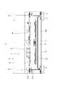
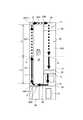
図2は電子看板1の縦断面を一部を省略して示す図であり、図3は看板本体2の横断面図である。また、図4は、循環流路30と液晶ディスプレイ10とを示す模式図である。
看板本体2が備える筐体8の内部には、図2及び図3に示すように、基板取付板20が設けられ、この基板取付板20により正面側空間21Aと背面側空間21Bとに仕切られており、正面側空間21Aには上記液晶ディスプレイ10が配置されている。また、基板取付板20には背面側空間21Bに臨む面に各種回路が設けられている。これらの回路には、例えば、液晶ディスプレイ10の表示等を制御する表示制御回路や、当該液晶ディスプレイ10に表示する映像や静止画像等から成る広告情報を外部から取得し保持する記憶回路、冷却ユニット6を駆動制御する制御部としてのコントローラ35(図5)等が含まれている。
FIG. 2 is a view in which a vertical section of theelectronic signboard 1 is partially omitted, and FIG. 3 is a cross-sectional view of thesignboard body 2. FIG. 4 is a schematic diagram showing thecirculation flow path 30 and theliquid crystal display 10.
As shown in FIGS. 2 and 3, aboard mounting plate 20 is provided inside thehousing 8 included in thesignboard body 2, and is partitioned into a front side space 21 </ b> A and a back side space 21 </ b> B by theboard mounting plate 20. Theliquid crystal display 10 is arranged in thefront space 21A. The circuitboard mounting plate 20 is provided with various circuits on the surface facing theback space 21B. These circuits include, for example, a display control circuit that controls the display of theliquid crystal display 10, a storage circuit that acquires and holds advertisement information including images and still images displayed on theliquid crystal display 10 from the outside, and acooling unit 6 includes a controller 35 (FIG. 5) or the like as a control unit for driving and controlling themotor 6.

液晶ディスプレイ10は、平面型ディスプレイであり、表示パネル22を備える。この表示パネル22には用途に応じて種々の形状のものが採用できる。本実施形態の液晶ディスプレイ10では、表示パネル22が縦長の長方形とされている。この液晶ディスプレイ10は、筐体8の正面側空間21Aに形成した密封空間28内に、周囲に空気が循環する循環流路30を設けて固定されている。  Theliquid crystal display 10 is a flat display and includes adisplay panel 22. Thedisplay panel 22 can have various shapes depending on the application. In theliquid crystal display 10 of this embodiment, thedisplay panel 22 is a vertically long rectangle. Theliquid crystal display 10 is fixed in a sealedspace 28 formed in the front space 21 </ b> A of thehousing 8 by providing acirculation channel 30 through which air circulates.

循環流路30は、図2に示すように、密封空間28と液晶ディスプレイ10の間の隙間30A〜30Dから構成される。すなわち、正面側空間21Aの密封空間28には、表示パネル22の表示面11とガラス板12の問に隙間30Aが形成され、表示パネル22の上端部22Aとの間に隙間30Bが形成され、液晶ディスプレイ10の裏面との間に隙間30Cが形成され、表示パネル22の下端部22Bとの問に隙間30Dが形成されている。これらの隙間30A〜30Dは、表示パネル22の周囲でこの順に環状に繋がっており、表示パネル22を取り巻いている。上記ガラス板12は、その上端部の正面側への突出量が筐体8に設けたスペーサ60により調整可能にされている。  As shown in FIG. 2, thecirculation flow path 30 includesgaps 30 </ b> A to 30 </ b> D between the sealedspace 28 and theliquid crystal display 10. That is, in the sealedspace 28 of thefront side space 21A, agap 30A is formed between thedisplay surface 11 of thedisplay panel 22 and theglass plate 12, and agap 30B is formed between theupper end portion 22A of thedisplay panel 22, Agap 30 </ b> C is formed between the back surface of theliquid crystal display 10, and agap 30 </ b> D is formed with thelower end portion 22 </ b> B of thedisplay panel 22. Thesegaps 30 </ b> A to 30 </ b> D are connected in an annular shape around thedisplay panel 22 in this order, and surround thedisplay panel 22. Theglass plate 12 can be adjusted by aspacer 60 provided in thehousing 8 so that the upper end of theglass plate 12 protrudes toward the front side.

このような循環流路30を形成することにより、表示パネル22の表示面11側の部分で発生した熱は、循環流路30を通ることで、表示パネル22の裏面側へ効率良く移動する。すなわち、図4に示すように、筐体8の密封空間28において表示パネル22の裏面側に設けられた2個の循環用ファン50が動作することにより、図中矢印で示すように空気が循環され、表示面11側から裏面側に熱が輸送される。液晶ディスプレイ10の裏面には、表示面11側で発生した熱を回収する冷凍サイクル40が設けられている。  By forming such acirculation channel 30, the heat generated in thedisplay surface 11 side portion of thedisplay panel 22 passes through thecirculation channel 30 and efficiently moves to the back side of thedisplay panel 22. That is, as shown in FIG. 4, when twocirculation fans 50 provided on the back surface side of thedisplay panel 22 operate in the sealedspace 28 of thehousing 8, air circulates as indicated by arrows in the figure. Then, heat is transported from thedisplay surface 11 side to the back surface side. Arefrigeration cycle 40 that recovers heat generated on thedisplay surface 11 side is provided on the rear surface of theliquid crystal display 10.

冷凍サイクル40の概要は、図2に示すように、蒸発器42と、この蒸発器42の下側に配置された圧縮機44、凝縮器46及び膨張弁48とを有し、蒸発器42によって熱を回収し、回収した熱を凝縮器46によって放出する。すなわち、蒸発器42は、表示パネル22の下端部22B近傍の位置にて裏面側の隙間30C内に設置されており、循環流路30を流れる空気から熱を回収する。
また、圧縮機44、凝縮器46及び膨張弁48は、図2及び図4に示すように、それぞれ筐体8の下部であって密封空間28の外に配置されており、凝縮器46は筐体8に設けた例えば通気孔に面して配置され、凝縮器46に通風させて放熱させる放熱用ファン51が凝縮器46に隣接して配置され、この放熱用ファン51により送風することで、蒸発器42によって回収された熱を、上記通気孔を通じて外へ放出する。
As shown in FIG. 2, the outline of therefrigeration cycle 40 includes anevaporator 42, acompressor 44, acondenser 46, and anexpansion valve 48 disposed below theevaporator 42. Heat is recovered and the recovered heat is released by thecondenser 46. That is, theevaporator 42 is installed in thegap 30 </ b> C on the back surface side at a position near thelower end portion 22 </ b> B of thedisplay panel 22, and recovers heat from the air flowing through thecirculation channel 30.
Further, as shown in FIGS. 2 and 4, thecompressor 44, thecondenser 46, and theexpansion valve 48 are disposed at the lower part of thecasing 8 and outside the sealedspace 28, respectively. For example, aheat dissipating fan 51 that is disposed facing the vent hole provided in thebody 8 and that dissipates heat by ventilating thecondenser 46 is disposed adjacent to thecondenser 46, and is blown by theheat dissipating fan 51, The heat recovered by theevaporator 42 is released to the outside through the vent hole.

この構成によれば、重量のある冷凍サイクル40を電子看板1の下部に配置したため、電子看板1が低重心となり、設置環境が不安定な屋外での使用において、電子看板1の安定性が向上する。また、蒸発器42を密封空間28の下部に配置したため、密封空間28内の冷却効率が良く、表示パネル22で発生した熱が循環流路30の空気の循環の過程において蒸発器42によって効率良く回収され凝縮器46から効率良く筐体8に設けた通気孔を通じて外へ放出され、これにより、液晶ディスプレイ10が冷却される。また、蒸発器42と、圧縮機44、凝縮器46及び膨張弁48との配管効率も良い。  According to this configuration, since theheavy refrigeration cycle 40 is disposed below theelectronic signboard 1, theelectronic signboard 1 has a low center of gravity, and the stability of theelectronic signboard 1 is improved in outdoor use where the installation environment is unstable. To do. Further, since theevaporator 42 is disposed below the sealedspace 28, the cooling efficiency in the sealedspace 28 is good, and the heat generated in thedisplay panel 22 is efficiently handled by theevaporator 42 in the process of circulating the air in thecirculation channel 30. The recovered liquid is efficiently discharged from thecondenser 46 through the vent hole provided in thehousing 8, and theliquid crystal display 10 is thereby cooled. Also, the piping efficiency of theevaporator 42, thecompressor 44, thecondenser 46, and theexpansion valve 48 is good.

上記循環流路30には、図2に示すように、当該循環流路30内で空気を循環させて冷却風を生じさせる循環用ファン(送風ファン)50が設けられている。循環用ファン50は、循環流路30のうち、図2に示すように、液晶ディスプレイ10の背面側の隙間30Cの表示パネル22の上端部22A近傍の位置と、下端部22B近傍の位置とのそれぞれに配置されている。下端部22B側の循環用ファン50の下流に上記蒸発器42が配置される。図示は省略するが、それぞれの箇所では複数の循環用ファン50が流路の断面内(同一水平面内)に並列に配置されている。これら循環用ファン50は、基板取付板20に設けられたコントローラ35(図5)により駆動制御される。  As shown in FIG. 2, thecirculation channel 30 is provided with a circulation fan (blower fan) 50 that circulates air in thecirculation channel 30 to generate cooling air. As shown in FIG. 2, thecirculation fan 50 includes agap 30 </ b> C on the back side of theliquid crystal display 10 and a position near theupper end 22 </ b> A of thedisplay panel 22 and a position near thelower end 22 </ b> B. It is arranged in each. Theevaporator 42 is disposed downstream of thecirculation fan 50 on thelower end 22B side. Although not shown, a plurality ofcirculation fans 50 are arranged in parallel in the cross section of the flow path (in the same horizontal plane) at each location. Thesecirculation fans 50 are driven and controlled by a controller 35 (FIG. 5) provided on theboard mounting plate 20.

背面側に設けた各循環用ファン50は、循環流路30に沿って実線矢印A(図2、4、5)の方向へ冷却風を循環させる。すなわち、循環用ファン50が駆動することにより、表示面11側の隙間30A内を冷却風は、鉛直方向において隙間30Aの下端部の入口30A−2から上端部の出口30A−1に向けて流れ、そして当該隙間30Aの出口30A−1から表示パネル22の上端部22A側の隙間30Bを通って裏面側の隙間30Cへ流れる。この隙間30C内に流れ込んだ冷却風は、図4に示すように、鉛直方向において上から下へ流れ、蒸発器42を通過し、表示パネル22の下端部22B側の隙間30Dを通って表示面11側の隙間30Aへと戻る。  Eachcirculation fan 50 provided on the back side circulates the cooling air along thecirculation flow path 30 in the direction of the solid arrow A (FIGS. 2, 4, and 5). That is, when thecirculation fan 50 is driven, the cooling air flows in thegap 30A on thedisplay surface 11 side from thelower end inlet 30A-2 to theupper end outlet 30A-1 in the vertical direction. Then, the air flows from theoutlet 30A-1 of thegap 30A through thegap 30B on theupper end 22A side of thedisplay panel 22 to thegap 30C on the back surface side. As shown in FIG. 4, the cooling air flowing into thegap 30C flows from top to bottom in the vertical direction, passes through theevaporator 42, passes through thegap 30D on thelower end portion 22B side of thedisplay panel 22, and is displayed on the display surface. Return to the11th clearance 30A.

本実施形態の電子看板1では、隙間30Aの静圧によって液晶ディスプレイ10の表示面11が撓んで表示むらが発生することを防ぐため、隙間30Aの下端部22B側と上端部22A側のそれぞれに配置した循環用ファン50の風量や種類を調整している。
図4に示すように、循環流路30には、背面側の隙間30Cの上端部22Aと下端部22Bの2箇所に設けた循環用ファン50により冷却風が循環され、循環流路30の静圧は、上端部22Aの循環用ファン50の位置Y1と、下端部22Bの循環用ファン50の位置Y2とのそれぞれで不連続的に増大し、冷却風の流れに沿って漸次低下し、この静圧の低下の度合い(静圧の低下量/流路長)は、各隙間30A〜30Dの幅などの流路構造や、上端部22A及び下端部22Bのそれぞれの循環用ファン50の風量の違いに起因する圧力損失によって異なる。本実施形態の循環流路30にあっては、表示面11側の隙間30A、及び、当該隙間30Aと背面側の隙間30Cとを接続する隙間30B、30Dの3つに対して、裏面側の隙間30Cで静圧低下の度合いが緩やかになっている。このような静圧の低下の度合いの差を考慮して、表示面11の中央部X1(表示面11の高さをLとした場合にL/2の位置)での静圧と、背面側の中央部X2の位置での静圧とが略等しくなるように、上端部22A及び下端部22Bのそれぞれの循環用ファン50の風量(吹出口での静圧)が設定されている。
そして、背面側の中央部X2から下端部22Bの循環用ファン50(位置Y2)を通って表示面11の中央部X1に至る間(図4中、矢印Z1で示す)の圧力損失を当該下端部22Bの循環用ファン50が賄い、表示面11の中央部X1から上端部22Aの循環用ファン50(位置Y1)を通って背面側の中央部X2に至る間(図4中、矢印Z2で示す)の圧力損失を当該上端部22Aの循環用ファン50が賄うことで、表示面11の中央部X1と背面側の中央部X2の静圧差を無くすことができる。
In theelectronic signboard 1 of this embodiment, in order to prevent thedisplay surface 11 of theliquid crystal display 10 from being bent due to the static pressure of thegap 30A and causing display unevenness, thelower end 22B side and theupper end 22A side of thegap 30A are respectively provided. The air volume and type of the arrangedcirculation fan 50 are adjusted.
As shown in FIG. 4, the cooling air is circulated in thecirculation flow path 30 by thecirculation fans 50 provided at two locations of theupper end portion 22A and thelower end portion 22B of thegap 30C on the back side. The pressure increases discontinuously at each of the position Y1 of thecirculation fan 50 at theupper end 22A and the position Y2 of thecirculation fan 50 at thelower end 22B, and gradually decreases along the flow of the cooling air. The degree of reduction in static pressure (static pressure reduction amount / flow path length) is determined by the flow rate structure such as the width of eachgap 30A to 30D and the air volume of eachcirculation fan 50 at theupper end 22A and thelower end 22B. It depends on the pressure loss due to the difference. In thecirculation channel 30 of the present embodiment, the gap on the back surface side is smaller than thegap 30A on thedisplay surface 11 side and thegaps 30B and 30D that connect thegap 30A and thegap 30C on the back surface side. The degree of static pressure reduction is moderate in thegap 30C. Considering such a difference in the degree of decrease in static pressure, the static pressure at the center X1 of the display surface 11 (the position of L / 2 when the height of thedisplay surface 11 is L) and the back side The air volume (static pressure at the air outlet) of eachcirculation fan 50 at theupper end portion 22A and thelower end portion 22B is set so that the static pressure at the position of the central portion X2 is substantially equal.
Then, the pressure loss during the period from the center portion X2 on the back side to the center portion X1 of thedisplay surface 11 through the circulation fan 50 (position Y2) of thelower end portion 22B (indicated by an arrow Z1 in FIG. 4) Thecirculation fan 50 of theportion 22B covers the interval from the center portion X1 of thedisplay surface 11 through the circulation fan 50 (position Y1) of theupper end portion 22A to the center portion X2 on the back side (in FIG. 4, an arrow Z2). Thecirculation fan 50 of theupper end portion 22A covers the pressure loss of (shown), so that the static pressure difference between the central portion X1 of thedisplay surface 11 and the central portion X2 on the back side can be eliminated.

冷凍サイクル40は、液晶ディスプレイ10の発熱Wa(単位W)と、日射による発熱Wb(単位W)とが生じた場合でも、液晶ディスプレイ10の表示パネル22の温度を目標温度(単位℃)以下に維持できる冷却能力に設計されている。この目標温度は表示パネル22に画像が表示できなくなるという現象(いわゆる、ブラックアウト)が生じ得る温度(例えば65℃)よりも所定温度だけ低い温度(例えば60℃)に設定されている。また、この電子看板1は、日射が強く冷却能力が不足する場合(表示パネル22の温度が目標温度以下にならない場合)には、表示パネル22の輝度を低下させる機能も備えている。  In therefrigeration cycle 40, even when the heat generation Wa (unit W) of theliquid crystal display 10 and the heat generation Wb (unit W) due to solar radiation are generated, the temperature of thedisplay panel 22 of theliquid crystal display 10 is set to a target temperature (unit ° C) or less. Designed for cooling capacity that can be maintained. This target temperature is set to a temperature (for example, 60 ° C.) that is lower by a predetermined temperature than a temperature (for example, 65 ° C.) at which a phenomenon that an image cannot be displayed on the display panel 22 (so-called blackout) can occur. Theelectronic signboard 1 also has a function of reducing the brightness of thedisplay panel 22 when the solar radiation is strong and the cooling capacity is insufficient (when the temperature of thedisplay panel 22 does not fall below the target temperature).

これらの構成によれば、縦長の液晶ディスプレイ10を筐体8内に立てた状態で納め、冷却風を表示面11の下端部22Bから上端部22Aに向けて流す構成としたため、屋外設置時の日射の影響などで上端部22Aに溜まり易い熱気を効率良く表示面11側から排出することができ、当該表示面11の上端部22Aでのブラックアウトを防止することができる。また、循環用ファン50を背面側に配置する構成としたため、隙間30Aの幅を狭めて当該隙間30Aを通過する冷却風の流速を大きくできるため、表示面11を効率よく冷却することができる。また、循環用ファン50の下流に蒸発器42を配置する構成としたため、表示面11及び背面側の各種電気部品の発熱を効率よく蒸発器42で回収できる。  According to these configurations, since the vertically longliquid crystal display 10 is stood in thecasing 8 and the cooling air is flowed from thelower end portion 22B of thedisplay surface 11 toward theupper end portion 22A, Hot air that tends to accumulate in theupper end portion 22A due to the influence of solar radiation or the like can be efficiently discharged from thedisplay surface 11 side, and blackout at theupper end portion 22A of thedisplay surface 11 can be prevented. Further, since thecirculation fan 50 is arranged on the back side, the width of thegap 30A can be narrowed to increase the flow velocity of the cooling air passing through thegap 30A, so that thedisplay surface 11 can be efficiently cooled. In addition, since theevaporator 42 is disposed downstream of thecirculation fan 50, theevaporator 42 can efficiently recover the heat generated by the various electrical components on thedisplay surface 11 and the back side.

冷凍サイクル40は、液晶ディスプレイ10の表示パネル22の温度が目標温度より十分に低い間は、圧縮機44を停止させる、いわゆるサーモオフとなるが、サーモオフになってから、密封空間28においてガラス板12の内側に結露が発生することがあった。
この結露が発生する要因として、発明者は、次の知見を得た。すなわち、冷凍サイクル40が運転されている間(サーモオン)は、密封空間28内で蒸発器42が最も低温となり、密封空間28内の水分の一部が蒸発器42で結露するが、冷凍サイクル40がサーモオフになると、蒸発器42に高温の冷媒が流れ込み、蒸発器42の温度が上昇することで蒸発器42付近に凝縮していた水分が蒸発し、この水分が、密封空間28内において蒸発器42よりも低温となる場所で結露する。結露しやすい場所としては、本実施形態においては、冷風の循環風路である入口30A−2付近が最も低温になるため、例えば、ガラス板12の内側下部である。
そこで本実施形態の電子看板1では、サーモオン/サーモオフを切り替える際に、冷凍サイクル40を制御してガラス板12の内側等に結露を防止する運転を行う。
While the temperature of thedisplay panel 22 of theliquid crystal display 10 is sufficiently lower than the target temperature, therefrigeration cycle 40 is a so-called thermo-off in which thecompressor 44 is stopped, but after the thermo-off, theglass plate 12 in the sealedspace 28 is turned off. Condensation may occur on the inside.
The inventor has obtained the following knowledge as a cause of the occurrence of this condensation. That is, while therefrigeration cycle 40 is in operation (thermo-on), theevaporator 42 has the lowest temperature in the sealedspace 28 and a part of the water in the sealedspace 28 is condensed in theevaporator 42. When the thermostat is turned off, a high-temperature refrigerant flows into theevaporator 42, and the temperature of theevaporator 42 rises to evaporate the moisture condensed in the vicinity of theevaporator 42. This moisture is then evaporated in the sealedspace 28. Condensation occurs at a temperature lower than 42. As a place where condensation easily occurs, in the present embodiment, the vicinity of theinlet 30A-2, which is a circulating air passage for cold air, has the lowest temperature, and is, for example, the inner lower portion of theglass plate 12.
Therefore, in theelectronic signboard 1 of the present embodiment, when switching between thermo-on / thermo-off, therefrigeration cycle 40 is controlled so as to prevent condensation on the inside of theglass plate 12 or the like.

図5は、冷凍サイクル40の構成を詳細に示す図である。図5中の破線は制御ラインを示す。
この図5に示すように、冷凍サイクル40は、上述した蒸発器42、圧縮機44、凝縮器46及び膨張弁48に、圧縮機44の吸込管に設けられたアキュムレータ47を備えた冷媒管路を有し、圧縮機44はモーター43により駆動され、圧縮機44の吐出冷媒は凝縮器46に流入して凝縮される。凝縮器46で凝縮した液冷媒は膨張弁48により減圧されて蒸発器42に流入し、蒸発器42で蒸発して、アキュムレータ47を経て圧縮機44の吸込管に戻る。
本実施形態では、圧縮機44が、回転数一定のモーター43により駆動される定速圧縮機であり、循環用ファン50が回転数一定の定速ファンとして構成され、放熱用ファン51が回転数可変型のファンとして構成される場合を例に挙げて説明する。
FIG. 5 is a diagram showing the configuration of therefrigeration cycle 40 in detail. A broken line in FIG. 5 indicates a control line.
As shown in FIG. 5, therefrigeration cycle 40 includes a refrigerant pipe provided with anaccumulator 47 provided in the suction pipe of thecompressor 44 in theevaporator 42, thecompressor 44, thecondenser 46 and theexpansion valve 48 described above. Thecompressor 44 is driven by themotor 43, and the refrigerant discharged from thecompressor 44 flows into thecondenser 46 and is condensed. The liquid refrigerant condensed in thecondenser 46 is decompressed by theexpansion valve 48 and flows into theevaporator 42, evaporates in theevaporator 42, returns to the suction pipe of thecompressor 44 through theaccumulator 47.
In this embodiment, thecompressor 44 is a constant speed compressor driven by amotor 43 having a constant rotation speed, thecirculation fan 50 is configured as a constant speed fan having a constant rotation speed, and theheat dissipation fan 51 is A case where the fan is configured as a variable rotation speed fan will be described as an example.

冷凍サイクル40は、運転制御を行うためのコントローラ35を備え、モーター43の運転/停止、膨張弁48の弁開度、循環流路30内の空気を循環させる循環用ファン50の運転/停止及び回転数、及び、凝縮器46に送風して放熱させる放熱用ファン51の運転/停止及び回転数が、コントローラ35によって制御される。
また、コントローラ35には、圧縮機44のケース温度を計測(検出)する温度センサ36A、圧縮機44の吐出冷媒温度を計測する温度センサ36B、圧縮機44の吸込冷媒の温度を計測する温度センサ36C、蒸発器42に設けられ、蒸発器42における冷媒温度を計測する温度センサ36D、密封空間28内においてガラス板12の下部の温度を計測する36E、及び、表示パネル22の背面側の上部において、例えば基板取付板20に配設され、液晶ディスプレイ10の背面の温度を計測する温度センサ36Fが、それぞれ接続されている。コントローラ35は、各温度センサ36A〜36Fにより計測された温度に基づいて、モーター43、膨張弁48、循環用ファン50及び放熱用ファン51の動作を制御する。温度センサ36A〜36Fを用いた温度の計測は、コントローラ35が、各温度センサ36A〜36Fの検出値を取得し、この検出値を演算することで行われる。
Therefrigeration cycle 40 includes acontroller 35 for controlling operation, and operates / stops themotor 43, the valve opening degree of theexpansion valve 48, the operation / stop of thecirculation fan 50 that circulates the air in thecirculation flow path 30, and Thecontroller 35 controls the number of revolutions and the operation / stop and the number of revolutions of theheat dissipating fan 51 that blows and radiates heat to thecondenser 46.
Thecontroller 35 includes atemperature sensor 36A for measuring (detecting) the case temperature of thecompressor 44, atemperature sensor 36B for measuring the discharge refrigerant temperature of thecompressor 44, and a temperature sensor for measuring the temperature of the suction refrigerant of thecompressor 44. 36C, atemperature sensor 36D that is provided in theevaporator 42 and measures the refrigerant temperature in theevaporator 42, 36E that measures the temperature of the lower part of theglass plate 12 in the sealedspace 28, and the upper part on the back side of thedisplay panel 22 For example, a temperature sensor 36 </ b> F disposed on thesubstrate mounting plate 20 and measuring the temperature of the back surface of theliquid crystal display 10 is connected to each other. Thecontroller 35 controls the operation of themotor 43, theexpansion valve 48, thecirculation fan 50, and theheat dissipation fan 51 based on the temperatures measured by thetemperature sensors 36A to 36F. The temperature measurement using thetemperature sensors 36A to 36F is performed by thecontroller 35 acquiring the detection values of thetemperature sensors 36A to 36F and calculating the detection values.

図6は、コントローラ35が冷凍サイクル40の制御する動作を示すフローチャートである。
この図6に示す動作は、コントローラ35が冷凍サイクル40を運転開始(サーモオン)させてから、実行される。
コントローラ35は、冷凍サイクル40の運転を開始させてから、温度センサ36Fによって液晶ディスプレイ10の背面の温度を計測し(ステップS1)、計測した液晶ディスプレイ10の温度が、予め設定された規定温度T1より高いか否かを判別する(ステップS2)。規定温度T1は、上述した液晶ディスプレイ10の冷却の目標温度Tに相当し、この規定温度T1の設定値はコントローラ35が内蔵するメモリ(図示略)に記憶されている。液晶ディスプレイ10の温度が規定温度T1より高い場合(ステップS2;Yes)、コントローラ35は、冷凍サイクル40による冷却運転を継続するため、ステップS14に移行する。
FIG. 6 is a flowchart showing the operation of therefrigeration cycle 40 controlled by thecontroller 35.
The operation shown in FIG. 6 is executed after thecontroller 35 starts the operation of the refrigeration cycle 40 (thermo-on).
After starting the operation of therefrigeration cycle 40, thecontroller 35 measures the temperature of the back surface of theliquid crystal display 10 by thetemperature sensor 36F (step S1), and the measured temperature of theliquid crystal display 10 is a preset specified temperature T1. It is determined whether or not it is higher (step S2). The specified temperature T1 corresponds to the above-described target temperature T for cooling theliquid crystal display 10, and the set value of the specified temperature T1 is stored in a memory (not shown) built in thecontroller 35. When the temperature of theliquid crystal display 10 is higher than the specified temperature T1 (step S2; Yes), thecontroller 35 proceeds to step S14 in order to continue the cooling operation by therefrigeration cycle 40.

一方、液晶ディスプレイ10の温度が規定温度T1以下であった場合(ステップS2;No)、コントローラ35は、液晶ディスプレイ10の背面側に設けられた2個の循環用ファン50、50を停止させ(ステップS3)、放熱用ファン51の回転数を調整する(ステップS4)。コントローラ35は、ステップS3以後で結露の発生を防止するための運転制御を行い、密封空間28内に蒸発器42より低温の場所ができないように、蒸発器42を低温に保つ。この制御中、蒸発器42を低温に保つために圧縮機44がモーター43により駆動されるが、循環用ファン50が停止しているために蒸発器42で冷媒が完全に蒸発せず、液バックを起こすことが懸念される。液バックを防止するためには放熱用ファン51の回転数を低くして、凝縮器46での放熱を抑制し、冷却能力を低減させることが有効である。その一方で、放熱用ファン51の回転数が低すぎると、圧縮機44の吐出温度や圧縮機44のケース温度が高温となり、圧縮機44の信頼性への懸念がある。そこで、コントローラ35は、ステップS4において、放熱用ファン51の回転速度を、圧縮機44の吐出温度および/またはケース温度が規定値を越えないように、かつ、冷媒過熱度が規定値を確保するような速度に調整する。  On the other hand, when the temperature of theliquid crystal display 10 is equal to or lower than the specified temperature T1 (step S2; No), thecontroller 35 stops the twocirculation fans 50 and 50 provided on the back side of the liquid crystal display 10 ( Step S3), the number of rotations of theheat dissipation fan 51 is adjusted (Step S4). Thecontroller 35 performs operation control for preventing the occurrence of condensation after step S3, and keeps theevaporator 42 at a low temperature so that there is no place in the sealedspace 28 lower than theevaporator 42. During this control, thecompressor 44 is driven by themotor 43 to keep the evaporator 42 at a low temperature. However, since thecirculation fan 50 is stopped, the refrigerant is not completely evaporated by theevaporator 42, and the liquid back There is a concern to cause. In order to prevent liquid back, it is effective to reduce the cooling capacity by reducing the number of rotations of theheat dissipating fan 51 to suppress heat dissipating in thecondenser 46. On the other hand, if the rotational speed of theheat radiating fan 51 is too low, the discharge temperature of thecompressor 44 and the case temperature of thecompressor 44 become high, and there is a concern about the reliability of thecompressor 44. Therefore, in step S4, thecontroller 35 ensures the rotational speed of theheat dissipation fan 51 so that the discharge temperature and / or case temperature of thecompressor 44 does not exceed the specified value, and the refrigerant superheat degree is the specified value. Adjust to such a speed.

図7は、図6のステップS4に示した処理を詳細に示すフローチャートである。
コントローラ35は、まず、放熱用ファン51の回転数を所定回転数に設定する(ステップS21)。この回転数は、結露防止運転用の基準値として予め設定され、コントローラ35が内蔵するメモリ(図示略)に記憶されている。
その直後あるいは所定時間経過後、コントローラ35は、温度センサ36A〜36Dを用いて、圧縮機44のケース温度または圧縮機44の吐出冷媒の温度、圧縮機44の吸込冷媒の温度、蒸発器42における蒸発温度を計測する(ステップS22)。ここで、圧縮機44のケース温度と圧縮機44の吐出冷媒の温度はいずれか一方もしくは両方を計測すればよい。
FIG. 7 is a flowchart showing in detail the process shown in step S4 of FIG.
First, thecontroller 35 sets the rotational speed of theheat dissipation fan 51 to a predetermined rotational speed (step S21). This rotational speed is preset as a reference value for the dew condensation prevention operation, and is stored in a memory (not shown) built in thecontroller 35.
Immediately thereafter or after a predetermined time has elapsed, thecontroller 35 uses the temperature sensors 36 </ b> A to 36 </ b> D to cause the case temperature of thecompressor 44 or the temperature of the refrigerant discharged from thecompressor 44, the temperature of the suction refrigerant of thecompressor 44, The evaporation temperature is measured (step S22). Here, either one or both of the case temperature of thecompressor 44 and the temperature of the refrigerant discharged from thecompressor 44 may be measured.

コントローラ35は、計測した圧縮機44のケース温度または圧縮機44の吐出冷媒の温度と、規定温度T2とを比較する(ステップS23)。規定温度T2は、圧縮機44の過熱を防止するための基準として予め設定された温度値であり、コントローラ35のメモリ(図示略)に記憶されている。規定温度T2は、コントローラ35が圧縮機44のケース温度を計測する場合と、圧縮機44の吐出冷媒の温度を計測する場合とで異なった値としてもよい。圧縮機44のケース温度または圧縮機44の吐出冷媒の温度が規定温度T2以上であった場合(ステップS23;No)、コントローラ35は、圧縮機44を保護するために放熱用ファン51の回転数を所定幅だけ増大させ(ステップS24)、ステップS22に戻る。  Thecontroller 35 compares the measured case temperature of thecompressor 44 or the temperature of the refrigerant discharged from thecompressor 44 with the specified temperature T2 (step S23). The specified temperature T2 is a temperature value set in advance as a reference for preventing overheating of thecompressor 44, and is stored in a memory (not shown) of thecontroller 35. The specified temperature T2 may be a different value when thecontroller 35 measures the case temperature of thecompressor 44 and when the temperature of the refrigerant discharged from thecompressor 44 is measured. When the case temperature of thecompressor 44 or the temperature of the refrigerant discharged from thecompressor 44 is equal to or higher than the specified temperature T2 (step S23; No), thecontroller 35 rotates the rotational speed of theheat dissipation fan 51 in order to protect thecompressor 44. Is increased by a predetermined width (step S24), and the process returns to step S22.

圧縮機44のケース温度または圧縮機44の吐出冷媒の温度が規定温度T2以下であった場合(ステップS23;Yes)、コントローラ35は、圧縮機44の吸込冷媒の温度と蒸発器42における蒸発温度との温度差を求め、求めた温度差が規定値T3より大きいか否かを判別する(ステップS25)。規定値T3は、冷媒の過熱度が抑えられている場合の圧縮機44の吸込冷媒の温度と蒸発器42における蒸発温度との温度差の基準となる値であり、予め設定され、コントローラ35のメモリ(図示略)に記憶されている。圧縮機44の吸込冷媒の温度と蒸発器42における蒸発温度との温度差が規定値T3より小さい場合(ステップS25;No)、冷媒の過熱度がとれていないため、コントローラ35は、放熱用ファン51の回転数を所定幅だけ低減させ(ステップS26)、ステップS21に戻る。そして、圧縮機44のケース温度または圧縮機44の吐出冷媒の温度が規定温度T2より低いか否かが判定される。
また、圧縮機44の吸込冷媒の温度と蒸発器42における蒸発温度との温度差が規定値T3より大きい場合(ステップS25;Yes)には、冷媒の過熱度が十分にとれており、放熱用ファン51の回転数が好適な値になっていることになるので、コントローラ35は図6のステップS5に移行する。
When the case temperature of thecompressor 44 or the temperature of the refrigerant discharged from thecompressor 44 is equal to or lower than the specified temperature T2 (step S23; Yes), thecontroller 35 determines the temperature of the suction refrigerant of thecompressor 44 and the evaporation temperature of theevaporator 42. Is determined, and it is determined whether or not the calculated temperature difference is greater than a specified value T3 (step S25). The specified value T3 is a value that serves as a reference for the temperature difference between the temperature of the refrigerant sucked by thecompressor 44 and the evaporation temperature in theevaporator 42 when the degree of superheat of the refrigerant is suppressed. It is stored in a memory (not shown). When the temperature difference between the temperature of the refrigerant sucked by thecompressor 44 and the evaporation temperature in theevaporator 42 is smaller than the specified value T3 (step S25; No), since the degree of superheat of the refrigerant has not been taken, thecontroller 35 has a heat radiating fan. The number ofrotations 51 is reduced by a predetermined width (step S26), and the process returns to step S21. Then, it is determined whether or not the case temperature of thecompressor 44 or the temperature of the refrigerant discharged from thecompressor 44 is lower than the specified temperature T2.
In addition, when the temperature difference between the temperature of the refrigerant sucked by thecompressor 44 and the evaporation temperature in theevaporator 42 is larger than the specified value T3 (step S25; Yes), the degree of superheat of the refrigerant is sufficiently high, and thus for heat dissipation. Since the rotation speed of thefan 51 is a suitable value, thecontroller 35 proceeds to step S5 in FIG.

このように、図7に示した処理では、以下の(1)、(2)の条件が両方と成立するように、放熱用ファン51の回転数が調整される。
(1)圧縮機44のケース温度または圧縮機44の吐出冷媒の温度が規定温度T2より低い。すなわち、吐出冷媒の温度が十分に低い。
(2)圧縮機44の吸込冷媒の温度と蒸発器42における蒸発温度との温度差が規定値T3より大きい。すなわち、冷媒の過熱度が十分に確保されている。
これにより、冷凍サイクル40は、モーター43により圧縮機44が駆動されるサーモオンの状態とすることで蒸発器42を低温に保ち、ガラス板12内側の結露を防止できる。また、この運転制御を行っている間は、循環用ファン50を停止させ、放熱用ファン51の回転数を低下させるので、液晶ディスプレイ10を過剰に冷却することがなく、通常の液晶ディスプレイ10を冷却する運転時よりも消費電力を抑えることができる。
As described above, in the process shown in FIG. 7, the rotational speed of theheat dissipation fan 51 is adjusted so that the following conditions (1) and (2) are satisfied.
(1) The case temperature of thecompressor 44 or the temperature of the refrigerant discharged from thecompressor 44 is lower than the specified temperature T2. That is, the temperature of the discharged refrigerant is sufficiently low.
(2) The temperature difference between the suction refrigerant temperature of thecompressor 44 and the evaporation temperature in theevaporator 42 is larger than the specified value T3. That is, the degree of superheat of the refrigerant is sufficiently ensured.
Thereby, therefrigeration cycle 40 can maintain theevaporator 42 at a low temperature by setting the thermo-on state in which thecompressor 44 is driven by themotor 43, and can prevent condensation inside theglass plate 12. Further, during this operation control, thecirculation fan 50 is stopped and the rotational speed of theheat dissipating fan 51 is reduced, so that theliquid crystal display 10 is not excessively cooled and the normalliquid crystal display 10 is Power consumption can be suppressed compared to during cooling operation.

図5のステップS4でファンの回転数を調整して結露防止の運転に移行した後、コントローラ35は、再び温度センサ36Fにより液晶ディスプレイ10の温度を計測し(ステップS5)、計測した液晶ディスプレイ10の温度が規定温度T1より高いか否かを判別する(ステップS6)。ここで、液晶ディスプレイ10の温度が規定温度T1より高い場合(ステップS6;Yes)、コントローラ35は冷凍サイクル40により通常の冷却運転を行わせるため、停止していた循環用ファン50を始動させるとともに放熱用ファン51の回転数を通常運転時の回転数に戻して(ステップS7)、ステップS14に移行する。  After adjusting the number of rotations of the fan in step S4 in FIG. 5 and shifting to the operation to prevent dew condensation, thecontroller 35 again measures the temperature of theliquid crystal display 10 by thetemperature sensor 36F (step S5), and the measuredliquid crystal display 10 It is determined whether or not the temperature is higher than the specified temperature T1 (step S6). Here, when the temperature of theliquid crystal display 10 is higher than the specified temperature T1 (step S6; Yes), thecontroller 35 causes therefrigeration cycle 40 to perform a normal cooling operation. The rotational speed of theheat dissipation fan 51 is returned to the rotational speed during normal operation (step S7), and the process proceeds to step S14.

また、液晶ディスプレイ10の温度が規定温度T1以下である場合(ステップS6;No)、コントローラ35は、筐体8の前面、すなわちガラス板12近傍の温度を温度センサ36Eによって計測し(ステップS8)、計測した温度と規定温度T4とを比較する(ステップS9)。規定温度T4は、ガラス板12に結露しない状態か否かを判定する基準として予め設定された温度値であり、コントローラ35のメモリ(図示略)に記憶されている。温度センサ36Eにより計測した温度が規定温度T4以下であった場合(ステップS9;No)、コントローラ35は、結露防止運転を継続するため、ステップS5に戻る。
一方、温度センサ36Eにより計測した温度が規定温度T4より高い場合(ステップS9;Yes)、コントローラ35は、結露の心配がなくなったためモーター43及び放熱用ファン51を停止させてサーモオフに移行する(ステップS10)。
When the temperature of theliquid crystal display 10 is equal to or lower than the specified temperature T1 (step S6; No), thecontroller 35 measures the temperature of the front surface of thehousing 8, that is, the vicinity of theglass plate 12, with thetemperature sensor 36E (step S8). The measured temperature is compared with the specified temperature T4 (step S9). The specified temperature T4 is a temperature value set in advance as a reference for determining whether or not theglass plate 12 is not condensed, and is stored in a memory (not shown) of thecontroller 35. When the temperature measured by thetemperature sensor 36E is equal to or lower than the specified temperature T4 (step S9; No), thecontroller 35 returns to step S5 in order to continue the condensation prevention operation.
On the other hand, if the temperature measured by thetemperature sensor 36E is higher than the specified temperature T4 (step S9; Yes), thecontroller 35 stops themotor 43 and theheat dissipating fan 51 and shifts to thermo-off because there is no risk of condensation (step S9). S10).

サーモオフに移行した後、コントローラ35は、温度センサ36Fにより液晶ディスプレイ10の温度を計測し(ステップS11)、計測した液晶ディスプレイ10の温度が規定温度T1より高いか否かを判別する(ステップS12)。ここで、液晶ディスプレイ10の温度が規定温度T1以下の場合(ステップS12;No)、ステップS11に戻ってサーモオフの状態を継続する。なお、ステップS12からステップS11で液晶ディスプレイ10の温度計測を行うまでに、所定の長さのインターバルを設けてもよい。
液晶ディスプレイ10の温度が規定温度T1より高い場合(ステップS12;Yes)、コントローラ35は冷凍サイクル40により通常の冷却運転を行わせるため、停止していたモーター43、循環用ファン50及び放熱用ファン51を始動させて(ステップS13)、ステップS14に移行する。
After shifting to thermo-off, thecontroller 35 measures the temperature of theliquid crystal display 10 with thetemperature sensor 36F (step S11), and determines whether or not the measured temperature of theliquid crystal display 10 is higher than the specified temperature T1 (step S12). . Here, when the temperature of theliquid crystal display 10 is equal to or lower than the specified temperature T1 (step S12; No), the process returns to step S11 to continue the thermo-off state. Note that an interval of a predetermined length may be provided before the temperature measurement of theliquid crystal display 10 is performed from step S12 to step S11.
When the temperature of theliquid crystal display 10 is higher than the specified temperature T1 (step S12; Yes), thecontroller 35 causes therefrigeration cycle 40 to perform a normal cooling operation. Therefore, themotor 43, thecirculation fan 50, and the heat dissipation fan that have been stopped are stopped. 51 is started (step S13), and the process proceeds to step S14.

従って、電子看板1が備える冷凍サイクル40は、液晶ディスプレイ10の温度が規定温度T1より高い間は密封空間28内を冷却する冷却運転を行い、液晶ディスプレイ10の温度が規定温度T1以下となった場合には、すぐにサーモオフに移行しないで、結露を防止するための結露防止運転を行う。
このように、本実施形態によれば、液晶ディスプレイ10を筐体8に納め、筐体8内部に、液晶ディスプレイ10の表示面11と対向する位置にガラス板12を設け、表示面11とガラス板12の間に隙間30Aを設け、筐体8内部に蒸発器42を設け、蒸発器42で冷やされた空気を隙間30Aに導いた後蒸発器42へ戻す循環用ファン50を設け、蒸発器42に連結されて、液晶ディスプレイ10の下方に備えられた圧縮機44と、凝縮器46と、膨張弁48とを有する冷凍サイクル40を設けた電子看板1において、筐体8内部に備えられた液晶ディスプレイ10の冷却温度を検出する温度センサ36Fと、温度センサ36Fにより検出された温度に応じて、圧縮機44の動作中に循環用ファン50の回転を制御するコントローラ35と、を備えたので、液晶ディスプレイ10の冷却温度が目標温度に達してから、圧縮機44を運転させるとともに循環用ファン50及び放熱用ファン51を制御し、液晶ディスプレイ10及び密封空間28を過度に冷却することなく、蒸発器42を低温に保つことができる。これにより、密封空間28におけるガラス板12の内側等の結露を防止することができ、液晶ディスプレイ10の視認性の低下等を防止できる。
Therefore, therefrigeration cycle 40 included in theelectronic signboard 1 performs a cooling operation for cooling the inside of the sealedspace 28 while the temperature of theliquid crystal display 10 is higher than the specified temperature T1, and the temperature of theliquid crystal display 10 becomes equal to or lower than the specified temperature T1. In such a case, a dew condensation prevention operation is performed to prevent dew condensation without immediately shifting to thermo-off.
As described above, according to the present embodiment, theliquid crystal display 10 is housed in thehousing 8, and theglass plate 12 is provided in thehousing 8 at a position facing thedisplay surface 11 of theliquid crystal display 10. Agap 30A is provided between theplates 12, anevaporator 42 is provided inside thehousing 8, acirculation fan 50 is provided for returning the air cooled by theevaporator 42 to thegap 30A and then returning to theevaporator 42. 42, theelectronic signboard 1 provided with arefrigeration cycle 40 having acompressor 44, acondenser 46, and anexpansion valve 48 provided below theliquid crystal display 10. Atemperature sensor 36F that detects the cooling temperature of theliquid crystal display 10 and acontroller 35 that controls the rotation of thecirculation fan 50 during operation of thecompressor 44 in accordance with the temperature detected by thetemperature sensor 36F. Therefore, after the cooling temperature of theliquid crystal display 10 reaches the target temperature, thecompressor 44 is operated, and thecirculation fan 50 and theheat dissipation fan 51 are controlled to make theliquid crystal display 10 and the sealedspace 28 excessive. Theevaporator 42 can be kept at a low temperature without cooling. Thereby, dew condensation such as the inside of theglass plate 12 in the sealedspace 28 can be prevented, and a decrease in the visibility of theliquid crystal display 10 can be prevented.

また、本実施形態によれば、液晶ディスプレイ10は、筐体8の密封空間28内に配置され、密封空間28は、筐体8とガラス板12で形成され、密封空間28内に蒸発器42と循環用ファン50が設けられている。これにより、密封空間28の内部に蒸発器42で冷却された空気を循環させて、液晶ディスプレイ10の発熱および日射等による熱を効果的に冷却できる。  Further, according to the present embodiment, theliquid crystal display 10 is disposed in the sealedspace 28 of thehousing 8, and the sealedspace 28 is formed by thehousing 8 and theglass plate 12, and theevaporator 42 is contained in the sealedspace 28. And acirculation fan 50 is provided. As a result, the air cooled by theevaporator 42 is circulated inside the sealedspace 28, and the heat generated by theliquid crystal display 10 and the heat generated by solar radiation can be effectively cooled.

本実施形態によれば、コントローラ35は、温度センサ36Fにより検出された液晶ディスプレイ10の背面側の温度に応じて、圧縮機44の動作中に、循環用ファン50とともに凝縮器46の放熱用ファン51の回転を制御する。これにより、液晶ディスプレイ10の冷却温度が目標温度に達してから、圧縮機44を運転させた状態で循環用ファン50及び放熱用ファン51を制御して、凝縮器46における熱交換量を調整するので、液晶ディスプレイ10及び密封空間28を過度に冷却することなく、蒸発器42を低温に保ち、密封空間28における結露を防止できる。  According to the present embodiment, thecontroller 35 uses thecirculation fan 50 and the heat dissipating fan of thecondenser 46 during the operation of thecompressor 44 according to the temperature on the back side of theliquid crystal display 10 detected by thetemperature sensor 36F. The rotation of 51 is controlled. Thereby, after the cooling temperature of theliquid crystal display 10 reaches the target temperature, thecirculation fan 50 and theheat dissipating fan 51 are controlled in a state where thecompressor 44 is operated, and the heat exchange amount in thecondenser 46 is adjusted. Therefore, theevaporator 42 can be kept at a low temperature without excessively cooling theliquid crystal display 10 and the sealedspace 28, and condensation in the sealedspace 28 can be prevented.

また、本実施形態によれば、コントローラ35は、圧縮機44の吸込冷媒の温度と蒸発器42における蒸発温度との温度差が予め設定された値を超えるように循環用ファン50と放熱用ファン51とを制御する。これにより、密封空間28及び液晶ディスプレイ10を過剰に冷却しないように圧縮機44を運転させて結露を防止することができ、かつ、圧縮機44への液バックを防止できる。  Further, according to the present embodiment, thecontroller 35 allows thecirculation fan 50 and the heat dissipation fan so that the temperature difference between the suction refrigerant temperature of thecompressor 44 and the evaporation temperature in theevaporator 42 exceeds a preset value. 51. As a result, thecompressor 44 can be operated so as not to excessively cool the sealedspace 28 and theliquid crystal display 10 to prevent condensation, and liquid back to thecompressor 44 can be prevented.

また、本実施形態によれば、コントローラ35は、圧縮機44の吸込冷媒の温度と蒸発器42における蒸発温度との温度差が予め設定された値を超え、かつ、圧縮機44のケース温度または圧縮機44の吐出温度が所定温度を超えないように、循環用ファン50と放熱用ファン51との回転数を制御する。これにより、密封空間28及び液晶ディスプレイ10を過剰に冷却しないように圧縮機44を運転させて結露を防止することができ、かつ、圧縮機44への液バックと圧縮機44の過熱を防止できる。  Further, according to the present embodiment, thecontroller 35 is configured such that the temperature difference between the temperature of the suction refrigerant of thecompressor 44 and the evaporation temperature of theevaporator 42 exceeds a preset value, and the case temperature of thecompressor 44 or The rotational speeds of thecirculation fan 50 and theheat dissipation fan 51 are controlled so that the discharge temperature of thecompressor 44 does not exceed a predetermined temperature. Accordingly, thecompressor 44 can be operated so as not to excessively cool the sealedspace 28 and theliquid crystal display 10 to prevent dew condensation, and liquid back to thecompressor 44 and overheating of thecompressor 44 can be prevented. .

さらに、本実施形態によれば、蒸発器42を液晶ディスプレイ10の背面側に設け、循環用ファン50を、隙間30Aと表示パネル22の背面側とに循環させるよう配置しているので、表示パネル22による表示を妨げない位置に蒸発器42を配置し、この蒸発器42により冷却された空気を循環用ファン50によって隙間30Aに送って循環させることで、冷凍サイクル40によって筐体8内部を効果的に冷却できる。
さらにまた、本実施形態によれば、密封空間28において結露の可能性がある所定位置に温度センサ36Eを設け、コントローラ35は、結露防止運転中に,温度センサ36Eにより検出された温度が予め設定された規定温度T4より高くなった場合には、圧縮機44及び放熱用ファン51を停止させる。すなわち、結露防止運転中に、ガラス板12の近傍等の結露しやすい場所における温度が規定温度T4より高くなり、結露しにくい状態になった場合には、結露防止運転をやめてサーモオフに移行するので、結露を確実に防止し、かつ、不要な運転を行わずに消費電力を抑えることができる。さらに、結露防止運転においては循環用ファン50を停止させるとともに放熱用ファン51の回転数を必要最小限の回転数まで低下させるので、通常の冷却運転よりも消費電力を抑えることができる。
Furthermore, according to the present embodiment, theevaporator 42 is provided on the back side of theliquid crystal display 10, and thecirculation fan 50 is arranged to circulate between thegap 30A and the back side of thedisplay panel 22. Theevaporator 42 is disposed at a position that does not obstruct the display by theair 22, and the air cooled by theevaporator 42 is circulated by being sent to thegap 30 </ b> A by thecirculation fan 50, so that the inside of thehousing 8 is effected by therefrigeration cycle 40. Can be cooled.
Furthermore, according to the present embodiment, thetemperature sensor 36E is provided at a predetermined position where there is a possibility of condensation in the sealedspace 28, and thecontroller 35 presets the temperature detected by thetemperature sensor 36E during the condensation prevention operation. When the temperature becomes higher than the specified temperature T4, thecompressor 44 and theheat dissipation fan 51 are stopped. That is, during the condensation prevention operation, if the temperature in a place where condensation is likely to occur, such as in the vicinity of theglass plate 12, is higher than the specified temperature T4 and the condensation is difficult to occur, the condensation prevention operation is stopped and the thermo-off is performed. Condensation can be reliably prevented and power consumption can be suppressed without performing unnecessary operation. Furthermore, in the dew condensation prevention operation, thecirculation fan 50 is stopped and the rotation speed of theheat dissipation fan 51 is reduced to the minimum rotation speed, so that power consumption can be suppressed as compared with the normal cooling operation.

なお、上記の説明では圧縮機44が定速圧縮機、循環用ファン50が定速ファン、放熱用ファン51が回転数可変型のファンとして構成される場合を例に挙げて説明したが、例えば、循環用ファン50を回転数可変型のファンとして構成することもできる。
この場合、コントローラ35は、図6のステップS3で循環用ファン50を停止させず、循環用ファン50の回転数を通常より低下させ、ステップS4(図7のステップS21〜26)の処理においては、放熱用ファン51の回転数とともに循環用ファン50の回転数を調整すればよい。この動作において、循環用ファン50及び放熱用ファン51の回転数は、上述した条件(1)及び(2)が両方とも満たされるように調整される。
In the above description, the case where thecompressor 44 is configured as a constant speed compressor, thecirculation fan 50 is configured as a constant speed fan, and theheat radiation fan 51 is configured as a variable rotation speed fan is described as an example. Thecirculation fan 50 can also be configured as a variable rotation speed type fan.
In this case, thecontroller 35 does not stop thecirculation fan 50 in step S3 in FIG. 6 but reduces the rotation speed of thecirculation fan 50 from the normal level, and in the process in step S4 (steps S21 to S26 in FIG. 7). The rotational speed of thecirculation fan 50 may be adjusted together with the rotational speed of theheat dissipation fan 51. In this operation, the rotation speeds of thecirculation fan 50 and theheat dissipation fan 51 are adjusted so that both of the above conditions (1) and (2) are satisfied.

また、上記の構成は、インバータ圧縮機よりも安価な定速圧縮機を圧縮機44に用いる点で、コスト面で有利であるが、圧縮機44としてインバータ式の圧縮機を用いることもできる。この場合、コントローラ35は、ステップS4(図7のステップS21〜26)の処理において、放熱用ファン51の回転数、或いは、放熱用ファン51の回転数と循環用ファン50の回転数を調整し、さらに、圧縮機44の運転速度を調整すればよい。この動作において、圧縮機44の運転速度、循環用ファン50及び放熱用ファン51の回転数は、上述した条件(1)及び(2)が両方とも満たされるように調整される。
さらに、上記のいずれの場合においても、コントローラ35は、図6のステップS4(図7のステップS21〜26)の処理において膨張弁48の弁開度を調整してもよい。
The above configuration is advantageous in terms of cost in that a constant speed compressor that is cheaper than the inverter compressor is used for thecompressor 44, but an inverter type compressor can also be used as thecompressor 44. In this case, thecontroller 35 adjusts the rotation speed of theheat dissipation fan 51 or the rotation speed of theheat dissipation fan 51 and the rotation speed of thecirculation fan 50 in the process of step S4 (steps S21 to S26 in FIG. 7). Furthermore, the operating speed of thecompressor 44 may be adjusted. In this operation, the operation speed of thecompressor 44 and the rotational speeds of thecirculation fan 50 and theheat dissipation fan 51 are adjusted so that both of the above conditions (1) and (2) are satisfied.
Furthermore, in any of the above cases, thecontroller 35 may adjust the valve opening degree of theexpansion valve 48 in the process of step S4 in FIG. 6 (steps S21 to S26 in FIG. 7).

いずれの場合であっても、コントローラ35は、(1)圧縮機44の吐出冷媒が十分に冷却され、(2)冷媒の過熱度が十分に抑えられるように、冷凍サイクル40の運転を制御する。これにより、ガラス板12の近傍等が結露しやすい状態である間は蒸発器42を低温に保って、蒸発器42からの水分の蒸発を防ぎ、密封空間28内における結露の発生を防止できる。また、この結露防止運転中は、循環用ファン50の運転を停止するとともに放熱用ファン51の回転数を低減させ、消費電力を抑制し、密封空間28を過剰に冷却しない。さらに、循環用ファン50の停止により熱交換量が減少しても、放熱用ファン51の回転数を調整して風量を適正にすることで、液バックを防止し、かつ、圧縮機44の過熱を防止できる。  In any case, thecontroller 35 controls the operation of therefrigeration cycle 40 so that (1) the refrigerant discharged from thecompressor 44 is sufficiently cooled and (2) the degree of superheat of the refrigerant is sufficiently suppressed. . Thus, while the vicinity of theglass plate 12 is in a state where condensation is likely to occur, theevaporator 42 can be kept at a low temperature to prevent evaporation of moisture from theevaporator 42 and to prevent the formation of condensation in the sealedspace 28. Further, during the dew condensation prevention operation, the operation of thecirculation fan 50 is stopped and the rotational speed of theheat dissipation fan 51 is reduced, power consumption is suppressed, and the sealedspace 28 is not excessively cooled. Furthermore, even if the heat exchange amount decreases due to thecirculation fan 50 being stopped, by adjusting the rotational speed of theheat dissipating fan 51 to make the air flow appropriate, liquid back is prevented and thecompressor 44 is overheated. Can be prevented.

以上、実施形態に基づいて本発明を説明したが、本発明はこれに限定されるものではない。本実施形態においては、表示パネル22(平面型ディスプレイ)に液晶ディスプレイ10を用いた構成としたが、これに限らず、例えば、有機ELディスプレイやプラズマディスプレイ等の平面型ディスプレイを用いた構成としても良い。  While the present invention has been described based on the embodiments, the present invention is not limited to this. In the present embodiment, theliquid crystal display 10 is used for the display panel 22 (planar display). However, the present invention is not limited to this, and for example, a configuration using a flat display such as an organic EL display or a plasma display may be used. good.

また、本実施形態においては、温度センサ36Eをガラス板12の内側の下部近傍に設置し、この温度センサ36Eにより計測した温度が規定温度T4より高いか否かに基づいて、ガラス板12の内側で結露しやすいか否かを判別する例を挙げて説明下が、本発明はこれに限定されず、密封空間28内に結露しやすい場所があれば、より多くの温度センサを設置し、これら各温度センサにより計測した温度に基づいて、結露しやすい状態か否かを判別してもよく、密封空間28内で、ガラス板12の下部以外の場所に設けた温度センサを、温度センサ36Eに代えて用いることも勿論可能である。
また、本実施形態においては、圧縮機44の吐出冷媒温度が所定温度以内になるよう、放熱用ファン51の回転数を制御する構成としたが、圧縮機44の周面に温度センサを設け、圧縮機44の周面温度が所定温度以上にならないように放熱用ファン51の回転数を制御する構成としてもよい。
また、例えば、上記実施形態では膨張弁48を膨張手段として用いる構成について説明したが、流路抵抗が一定ないわゆるキャピラリーチューブを膨張手段として用いる構成としてもよい。特に、キャピラリーチューブと定速圧縮機44とを組み合わせて冷凍サイクル40を構成すれば、インバータ式の圧縮機や膨張弁を用いた場合と比較して、更に安価で構成可能であり、コスト面で有利である。
その他の細部構成等についても任意に変更可能であることは勿論である。
In the present embodiment, thetemperature sensor 36E is installed near the lower part inside theglass plate 12, and the inside of theglass plate 12 is determined based on whether the temperature measured by thetemperature sensor 36E is higher than the specified temperature T4. However, the present invention is not limited to this, and if there is a place where condensation easily occurs in the sealedspace 28, more temperature sensors can be installed. Based on the temperature measured by each temperature sensor, it may be determined whether or not condensation is likely to occur. A temperature sensor provided in a place other than the lower portion of theglass plate 12 in the sealedspace 28 is used as thetemperature sensor 36E. Of course, it can be used instead.
In the present embodiment, the rotational speed of theheat dissipating fan 51 is controlled so that the discharge refrigerant temperature of thecompressor 44 is within a predetermined temperature. However, a temperature sensor is provided on the peripheral surface of thecompressor 44, It is good also as a structure which controls the rotation speed of thefan 51 for thermal radiation so that the surrounding surface temperature of thecompressor 44 may not become more than predetermined temperature.
For example, in the above-described embodiment, the configuration using theexpansion valve 48 as the expansion means has been described. However, a so-called capillary tube having a constant flow path resistance may be used as the expansion means. In particular, if therefrigeration cycle 40 is configured by combining the capillary tube and theconstant speed compressor 44, it can be configured at a lower cost than the case where an inverter type compressor or expansion valve is used. It is advantageous.
Of course, other details and the like can be arbitrarily changed.

1 電子看板
2 看板本体
4 土台
6 冷却ユニット
8 筐体
9 開口
10 液晶ディスプレイ(平面型ディスプレイ)
11 表示面
12 ガラス板(透明板)
14 フレーム枠
22 表示パネル
28 密封空間
30 循環流路
30A 隙間
35 コントローラ(制御部)
36A〜36F 温度センサ
40 冷凍サイクル
42 蒸発器
44 圧縮機
46 凝縮器
48 膨張弁
50 循環用ファン
51 放熱用ファン
DESCRIPTION OFSYMBOLS 1Electronic signboard 2Signboard body 4Base 6Cooling unit 8Housing 9Opening 10 Liquid crystal display (flat display)
11 Display surface 12 Glass plate (transparent plate)
14Frame frame 22Display panel 28 Sealedspace 30 Circulatingflowpath 30A Clearance 35 Controller (control unit)
36A to36F Temperature sensor 40Refrigeration cycle 42Evaporator 44Compressor 46Condenser 48Expansion valve 50 Fan forcirculation 51 Fan for heat dissipation

Claims (6)

Translated fromJapanese
平面型ディスプレイを筐体に納め、
前記筐体内部に、前記平面型ディスプレイの表示面と対向する位置に透明板を設け、前記表示面と前記透明板の間に隙間を設け、前記筐体内部に蒸発器を設け、前記蒸発器で冷やされた空気を前記隙間に導いた後前記蒸発器へ戻す循環用ファンを設け、前記蒸発器に連結されて、前記平面型ディスプレイの下方に備えられた圧縮機と、凝縮器と、膨張手段とを有する冷凍サイクルを設けた電子看板において、
前記筐体内部に備えられた前記平面型ディスプレイの冷却温度を検出する温度センサと、
前記温度センサにより検出された温度に応じて、前記圧縮機の動作中に前記循環用ファンの回転とともにと前記凝縮器の放熱用ファンの回転を制御する制御部と、
を備えたことを特徴とする電子看板。
Put the flat display in the case,
A transparent plate is provided inside the housing at a position facing the display surface of the flat display, a gap is provided between the display surface and the transparent plate, an evaporator is provided inside the housing, and the evaporator is cooled by the evaporator. A circulation fan that guides the generated air to the gap and then returns to the evaporator, is connected to the evaporator, and is provided below the flat display; a condenser; an expansion means; In an electronic signboard provided with a refrigeration cycle having
A temperature sensor for detecting a cooling temperature of the flat display provided in the housing;
A controller that controls rotation of the circulation fan and rotation of the heat dissipation fan of the condenser according to a temperature detected by the temperature sensor;
An electronic signboard characterized by comprising
前記平面型ディスプレイは、前記筐体の密封空間内に配置され、前記密封空間は、前記筐体と前記透明板で形成され、前記密封空間内に前記蒸発器と前記循環用ファンが設けられていることを特徴とする請求項1に記載の電子看板。  The flat display is disposed in a sealed space of the housing, the sealed space is formed by the housing and the transparent plate, and the evaporator and the circulation fan are provided in the sealed space. The electronic signboard according to claim 1, wherein: 前記制御部は、前記圧縮機の吸込冷媒の温度と前記蒸発器における蒸発温度との温度差が予め設定された値を超えるように前記循環用ファンと前記放熱用ファンとを制御することを特徴とする請求項1または2に記載の電子看板。  The control unit controls the circulation fan and the heat dissipating fan so that a temperature difference between a temperature of the suction refrigerant of the compressor and an evaporation temperature in the evaporator exceeds a preset value. The electronic signboard according to claim 1 or 2. 前記制御部は、前記圧縮機の吸込冷媒の温度と前記蒸発器における蒸発温度との温度差が予め設定された値を超え、かつ、前記圧縮機のケース温度または前記圧縮機の吐出温度が所定温度を超えないように、前記循環用ファンと前記放熱用ファンとの回転数を制御することを特徴とする請求項1または2に記載の電子看板。  The control unit has a temperature difference between a temperature of the suction refrigerant of the compressor and an evaporation temperature of the evaporator exceeding a preset value, and a case temperature of the compressor or a discharge temperature of the compressor is predetermined. The electronic signboard according to claim 1 or 2, wherein the number of rotations of the circulation fan and the heat dissipation fan is controlled so as not to exceed a temperature. 前記密封空間において結露の可能性がある所定位置に第2の温度センサを設け、
前記制御部は、前記圧縮機の動作中に前記循環用ファンと前記凝縮器の放熱用ファンとの回転を制御し、前記第2の温度センサにより検出された温度が予め設定された温度より高くなった場合には、前記圧縮機及び前記放熱用ファンを停止させることを特徴とすることを特徴とする請求項1乃至4のいずれかに記載の電子看板。
A second temperature sensor is provided at a predetermined position where condensation may occur in the sealed space;
The control unit controls the rotation of the circulation fan and the heat dissipation fan of the condenser during operation of the compressor, and the temperature detected by the second temperature sensor is higher than a preset temperature. The electronic signboard according to any one of claims 1 to 4, characterized in that the compressor and the heat dissipating fan are stopped when it becomes.
平面型ディスプレイを筐体に納め、前記筐体内部に、前記平面型ディスプレイの表示面と対向する位置に透明板を設け、前記表示面と前記透明板の間に隙間を設け、前記筐体内部に蒸発器を設け、前記蒸発器で冷やされた空気を前記隙間に導いた後前記蒸発器へ戻す循環用ファンを設け、前記蒸発器に連結されて、前記平面型ディスプレイの下方に備えられた圧縮機と、凝縮器と、膨張手段とを有する冷凍サイクルと、前記冷凍サイクルを制御する制御部とを設けた電子看板における冷却制御方法であって、
前記制御部により、
温度センサにより前記筐体内部に備えられた前記平面型ディスプレイの冷却温度を検出し、
検出された温度に応じて、前記圧縮機の動作中に前記循環用ファンの回転とともにと前記凝縮器の放熱用ファンの回転を制御すること、
を備えたことを特徴とする電子看板における冷却制御方法。
A flat display is housed in a housing, a transparent plate is provided inside the housing at a position facing the display surface of the flat display, a gap is provided between the display surface and the transparent plate, and evaporation is performed inside the housing. A compressor provided in the lower part of the flat display connected to the evaporator, provided with a circulation fan provided to return the air cooled by the evaporator to the gap and then returned to the evaporator And a cooling control method in an electronic signboard provided with a refrigeration cycle having a condenser and expansion means, and a control unit for controlling the refrigeration cycle,
By the control unit,
Detecting a cooling temperature of the flat display provided in the housing by a temperature sensor;
According to the detected temperature, controlling rotation of the heat dissipation fan of the condenser together with rotation of the circulation fan during operation of the compressor;
A cooling control method for an electronic signboard, comprising:
JP2009293895A2009-12-252009-12-25Electronic signboard and cooling control method for the samePendingJP2011133712A (en)

Priority Applications (1)

Application NumberPriority DateFiling DateTitle
JP2009293895AJP2011133712A (en)2009-12-252009-12-25Electronic signboard and cooling control method for the same

Applications Claiming Priority (1)

Application NumberPriority DateFiling DateTitle
JP2009293895AJP2011133712A (en)2009-12-252009-12-25Electronic signboard and cooling control method for the same

Publications (1)

Publication NumberPublication Date
JP2011133712Atrue JP2011133712A (en)2011-07-07

Family

ID=44346510

Family Applications (1)

Application NumberTitlePriority DateFiling Date
JP2009293895APendingJP2011133712A (en)2009-12-252009-12-25Electronic signboard and cooling control method for the same

Country Status (1)

CountryLink
JP (1)JP2011133712A (en)

Cited By (6)

* Cited by examiner, † Cited by third party
Publication numberPriority datePublication dateAssigneeTitle
KR101336970B1 (en)*2013-04-182013-12-04주식회사 엣지아이앤디The device of preventing fog for display apparatus
CN103903514A (en)*2012-12-252014-07-02苏州昆拓热控系统股份有限公司Digital display device
CN104457068A (en)*2014-12-082015-03-25中国船舶重工集团公司第七一六研究所Modularized water-cooling cabinet and noise redundancy control method thereof
JP2015072161A (en)*2013-10-022015-04-16エスペック株式会社 Environmental test equipment
CN107270487A (en)*2017-07-102017-10-20珠海格力电器股份有限公司Method, device and system for controlling heat dissipation of air conditioner driving board
CN115342444A (en)*2022-08-182022-11-15珠海格力电器股份有限公司Cabinet air conditioner and control method thereof

Cited By (6)

* Cited by examiner, † Cited by third party
Publication numberPriority datePublication dateAssigneeTitle
CN103903514A (en)*2012-12-252014-07-02苏州昆拓热控系统股份有限公司Digital display device
KR101336970B1 (en)*2013-04-182013-12-04주식회사 엣지아이앤디The device of preventing fog for display apparatus
JP2015072161A (en)*2013-10-022015-04-16エスペック株式会社 Environmental test equipment
CN104457068A (en)*2014-12-082015-03-25中国船舶重工集团公司第七一六研究所Modularized water-cooling cabinet and noise redundancy control method thereof
CN107270487A (en)*2017-07-102017-10-20珠海格力电器股份有限公司Method, device and system for controlling heat dissipation of air conditioner driving board
CN115342444A (en)*2022-08-182022-11-15珠海格力电器股份有限公司Cabinet air conditioner and control method thereof

Similar Documents

PublicationPublication DateTitle
US20210165472A1 (en)Display device
US8319936B2 (en)Display device with cooling control
US8270163B2 (en)Display apparatus
JP2011133712A (en)Electronic signboard and cooling control method for the same
JP5653872B2 (en) Case cooling system
JP5669407B2 (en) Electric box for outdoor unit, outdoor unit and air conditioner
US20110019160A1 (en)Image display apparatus
EP2844049B1 (en)Air-cooled case
CN102997345B (en)The cooling system of air-conditioner control box and configure its air-conditioning
JP4895848B2 (en) Cooling system
JP2012118130A (en)Display device and electronic apparatus
JP2013096642A (en)Cooling device and air conditioner with the same
JP2015127622A (en)Electric component unit
KR100446084B1 (en)Image display apparatus
JP5677223B2 (en) Air conditioner
KR20120059864A (en)LCD and LED display board applying air conditoning system with cooling module
KR101161370B1 (en)Apparatus for Radiating Heat of Outdoor Display Panel
JP5356093B2 (en) Image display device
JP2013096641A (en)Cooling device and air conditioner with the same
US20100154466A1 (en)Temperature-controlled cabinet
JP2005076921A (en)Refrigerator
JP2013020367A (en)Cooling system for electronic equipment
JP2014207294A (en)Electrical equipment
JP2010085054A (en)Outdoor unit for air-conditioning apparatus
JP2011180181A (en)Electronic signboard

[8]ページ先頭

©2009-2025 Movatter.jp