JP2011131444A - Stapler for saddle stitching - Google Patents
Stapler for saddle stitchingDownload PDFInfo
- Publication number
- JP2011131444A JP2011131444AJP2009291554AJP2009291554AJP2011131444AJP 2011131444 AJP2011131444 AJP 2011131444AJP 2009291554 AJP2009291554 AJP 2009291554AJP 2009291554 AJP2009291554 AJP 2009291554AJP 2011131444 AJP2011131444 AJP 2011131444A
- Authority
- JP
- Japan
- Prior art keywords
- clincher
- positioning
- positioning means
- driver
- support portion
- Prior art date
- Legal status (The legal status is an assumption and is not a legal conclusion. Google has not performed a legal analysis and makes no representation as to the accuracy of the status listed.)
- Pending
Links
- 238000003825pressingMethods0.000claimsdescription9
- 238000003860storageMethods0.000claimsdescription3
- 238000000034methodMethods0.000description10
- 230000006835compressionEffects0.000description6
- 238000007906compressionMethods0.000description6
- 238000006073displacement reactionMethods0.000description5
- 238000005452bendingMethods0.000description2
- 230000007547defectEffects0.000description1
- 238000005516engineering processMethods0.000description1
- 238000004519manufacturing processMethods0.000description1
Images


Classifications
- B—PERFORMING OPERATIONS; TRANSPORTING
- B27—WORKING OR PRESERVING WOOD OR SIMILAR MATERIAL; NAILING OR STAPLING MACHINES IN GENERAL
- B27F—DOVETAILED WORK; TENONS; SLOTTING MACHINES FOR WOOD OR SIMILAR MATERIAL; NAILING OR STAPLING MACHINES
- B27F7/00—Nailing or stapling; Nailed or stapled work
- B27F7/006—Nailing or stapling machines provided with means for operating on discrete points
- B—PERFORMING OPERATIONS; TRANSPORTING
- B27—WORKING OR PRESERVING WOOD OR SIMILAR MATERIAL; NAILING OR STAPLING MACHINES IN GENERAL
- B27F—DOVETAILED WORK; TENONS; SLOTTING MACHINES FOR WOOD OR SIMILAR MATERIAL; NAILING OR STAPLING MACHINES
- B27F7/00—Nailing or stapling; Nailed or stapled work
- B27F7/17—Stapling machines
- B27F7/19—Stapling machines with provision for bending the ends of the staples on to the work
- B—PERFORMING OPERATIONS; TRANSPORTING
- B65—CONVEYING; PACKING; STORING; HANDLING THIN OR FILAMENTARY MATERIAL
- B65H—HANDLING THIN OR FILAMENTARY MATERIAL, e.g. SHEETS, WEBS, CABLES
- B65H37/00—Article or web delivery apparatus incorporating devices for performing specified auxiliary operations
- B65H37/04—Article or web delivery apparatus incorporating devices for performing specified auxiliary operations for securing together articles or webs, e.g. by adhesive, stitching or stapling
- B—PERFORMING OPERATIONS; TRANSPORTING
- B65—CONVEYING; PACKING; STORING; HANDLING THIN OR FILAMENTARY MATERIAL
- B65H—HANDLING THIN OR FILAMENTARY MATERIAL, e.g. SHEETS, WEBS, CABLES
- B65H2408/00—Specific machines
- B65H2408/10—Specific machines for handling sheet(s)
- B65H2408/12—Specific machines for handling sheet(s) stapler arrangement
- B65H2408/122—Specific machines for handling sheet(s) stapler arrangement movable stapler
- B65H2408/1222—Specific machines for handling sheet(s) stapler arrangement movable stapler movable transversely to direction of transport
- B—PERFORMING OPERATIONS; TRANSPORTING
- B65—CONVEYING; PACKING; STORING; HANDLING THIN OR FILAMENTARY MATERIAL
- B65H—HANDLING THIN OR FILAMENTARY MATERIAL, e.g. SHEETS, WEBS, CABLES
- B65H2408/00—Specific machines
- B65H2408/10—Specific machines for handling sheet(s)
- B65H2408/12—Specific machines for handling sheet(s) stapler arrangement
- B65H2408/125—Specific machines for handling sheet(s) stapler arrangement head unit separate from anvil unit
Landscapes
- Engineering & Computer Science (AREA)
- Mechanical Engineering (AREA)
- Life Sciences & Earth Sciences (AREA)
- Forests & Forestry (AREA)
- Textile Engineering (AREA)
- Portable Nailing Machines And Staplers (AREA)
- Dovetailed Work, And Nailing Machines And Stapling Machines For Wood (AREA)
- Folding Of Thin Sheet-Like Materials, Special Discharging Devices, And Others (AREA)
Abstract
Description
Translated fromJapanese本発明は、中綴じ用ステープラに関する。 The present invention relates to a saddle stitch stapler.
一般に、中綴じ用ステープラはステープルを打出すドライバと打ち出されて被綴り用紙を貫通したステープルの脚部を折り曲げるクリンチャとを上下に分離して配置したもので、ステープルの脚部を折り曲げるクリンチャ方式は、可動クリンチャ方式と固定クリンチャ方式とに大別される。可動クリンチャ方式は、ステープルが被綴り用紙を貫通しきった後、可動クリンチャが回動してその脚部を折り曲げる方式であり、固定クリンチャ方式は、ステープルの脚部が被綴り用紙を貫通した直後から、固定されたクリンチャの溝に案内されて折り曲げられるようにしたものである。 In general, a saddle stitch stapler is arranged by separating a clincher which folds a leg of a staple which has been pierced and penetrates a stapled paper, and a clincher method which folds the leg of a staple. The movable clincher method and the fixed clincher method are roughly classified. The movable clincher method is a method in which after the staple has completely penetrated the stapled paper, the movable clincher rotates and bends its leg portion. The fixed clincher method is immediately after the staple leg portion penetrates the stapled paper. , Which is guided and bent in the groove of the fixed clincher.
これらの2つの方式のうち、固定クリンチャ方式は、安価な低速機から高価な高速機のフィニッシャまで幅広く採用されている。その理由として、クリンチャの駆動機構を必要とせず、構造が簡単であるからコストを低く抑えることができ、省スペースが可能となる、中綴じ冊子の場合、冊子を貫通した両側のステープルの脚部が直線上に並ぶので綴り位置を折り目に合わせることができる、等を挙げることができる。また、通常はフィニッシャの製造コストの都合上、一度に厚い用紙を折る機構に関する技術が確立されていないから、ステープラには25〜30枚程度の綴り能力で十分で、それよりもコストの低減が求められている。 Of these two methods, the fixed clincher method is widely used from an inexpensive low-speed machine to an expensive high-speed machine finisher. The reason for this is that a clincher drive mechanism is not required, the structure is simple, the cost can be kept low, and space can be saved. In the case of a saddle-stitched booklet, the legs of the staples on both sides that penetrate the booklet Are arranged on a straight line so that the spelling position can be adjusted to the crease. In addition, because of the manufacturing cost of the finisher, since a technology for folding a thick sheet at a time has not been established, a binding capacity of about 25 to 30 sheets is sufficient for the stapler, and the cost can be reduced more than that. It has been demanded.
ところで、固定クリンチャの場合、ドライバとクリンチャを取り付けた部材が前後に多少位置ずれしても、ドライバに打ち出されたステープルの脚部は直線上に並ぶように折り曲げられるため、ステープルの転びやステープルの脚部の重なりどの不具合がなくクリンチャ溝で拾いこみやすいので、前後の位置ずれに対しては、許容範囲は比較的広い。しかしながら、左右方向の位置ずれに対しては、クリンチャが固定され、左右対称形状であるから、少しずれただけでステープルの一方の脚部の先端と他方の脚部の先端が当るクリンチャ溝の状況は全く異なってしまう。つまり、一方の脚部の先端がクリンチャの溝の一端の傾斜面の高い部位に当ると、他方の脚部の先端はクリンチャの他端の傾斜面の低い部位に当ることになり、両側の脚部が均等に曲がりにくい。したがって、この場合の許容範囲は小さく、非常にシビアな精度を求められるから、調芯のために大がかりな治具や複雑な構造を採用せざるを得なかった。 By the way, in the case of the fixed clincher, even if the driver and the member to which the clincher is attached are slightly displaced forward and backward, the staple leg portions that are driven out by the driver are bent so as to be aligned in a straight line. Legs overlap Since there is no defect and it is easy to pick up in the clincher groove, the tolerance is relatively wide with respect to the front and rear positional deviation. However, since the clincher is fixed and symmetrical with respect to the lateral displacement, the state of the clincher groove where the tip of one leg of the staple hits the tip of the other leg with a slight deviation Will be completely different. In other words, if the tip of one leg hits a high part of the inclined surface at one end of the clincher groove, the tip of the other leg hits a low part of the inclined surface at the other end of the clincher. The part is difficult to bend evenly. Accordingly, the allowable range in this case is small, and very severe accuracy is required, so a large jig or a complicated structure has to be employed for alignment.
昨今、ドライバとクリンチャとをそれぞれタイミングベルト(搬送ベルト)により左右方向に移動可能とし、さらに両側のベルトを同軸に設けられたプーリに巻き懸けることにより、ドライバ側とクリンチャ側とが同時に同方向に同量だけ移動して常にドライバとクリンチャの上下の位置関係が同じに保たれた状態で綴じ作動できるようにする構成の両側移動機構を備えたフィニッシャ(特許文献1参照)が提案されている。 Nowadays, the driver and the clincher can be moved in the left and right direction by the timing belt (conveyor belt), and the belt on both sides is wound around a coaxial pulley so that the driver side and the clincher side can simultaneously move in the same direction. There has been proposed a finisher (see Patent Document 1) having a double-side moving mechanism configured to move by the same amount so that the binding operation can be performed while the vertical positional relationship between the driver and the clincher is always kept the same.
しかしながら、特許文献1のように、クリンチャ側とドライバ側がどちらも、タイミングベルトによって搬送される方式は、タイミングベルトの伸びや撓み等の原因によりクリンチャ側とドライバ側との相対的な位置関係を一定に保つことが困難であった。このため、固定クリンチャを採用した上下分離機であって両側移動機構を有するフィニッシャの製品化に際しては、クリンチャ側とドライバ側との相対的な位置関係を一定に保つため、高価なステッピングモータを用いて制御を行なうことなどが必要であった。このため、フィニッシャそのものも高価となってしまい、固定クリンチャを用いた方式で、ドライバ側とクリンチャ側とを分離して移動させるフィニッシャを実現することは、非常に困難であった。 However, as in Patent Document 1, the method in which both the clincher side and the driver side are conveyed by the timing belt has a constant relative positional relationship between the clincher side and the driver side due to the expansion or deflection of the timing belt. It was difficult to keep on. For this reason, when commercializing a finisher that uses a fixed clincher and has a both-side moving mechanism, an expensive stepping motor is used to keep the relative positional relationship between the clincher side and the driver side constant. It was necessary to perform control. For this reason, the finisher itself is also expensive, and it has been very difficult to realize a finisher that moves the driver side and the clincher side separately by a method using a fixed clincher.
本発明は上記問題点を解消し、簡単な構造によって、綴り時にドライバとクリンチャとを精度よく位置決めすることができる中綴じ用ステープラを提供することをその課題とする。 An object of the present invention is to provide a saddle stitching stapler that can solve the above-described problems and can accurately position a driver and a clincher at the time of binding with a simple structure.
上記課題を解決するため、請求項1に係る発明は、ステープル収納用マガジンから供給されたステープルを被綴り用紙に向けて打ち出すドライバ駆動機構を支持したドライバ支持部と、打ち出されたステープルを折り曲げるクリンチャを固定したクリンチャ支持部とを上下に分離して配置するとともに、上記両支持部を同時に左右方向に略同量だけ平行にスライド可能に設け、上記両支持部間に被綴り用紙をクランプした後に綴じ作動する中綴じ用ステープラにおいて、上記クリンチャ支持部又はドライバ支持部の近傍に位置決め手段を設け、上記クランプ作動に連動させて上記クリンチャ支持部又はドライバ支持部と位置決め手段とにそれぞれ設けた位置決め部同士を係合させることを特徴とする。 In order to solve the above-mentioned problem, a first aspect of the present invention is directed to a driver support portion that supports a driver driving mechanism that drives a staple supplied from a staple storage magazine toward a stapled paper, and a clincher that bends the staple that has been punched out. The clincher support part to which the clincher is fixed is arranged separately in the vertical direction, and both the support parts are provided so as to be slidable in parallel in substantially the same amount in the left-right direction, and after the stapled paper is clamped between the two support parts In the saddle stitching stapler that performs the binding operation, positioning means is provided in the vicinity of the clincher support portion or the driver support portion, and the positioning portions provided in the clincher support portion or the driver support portion and the positioning means in conjunction with the clamp operation. It is characterized by engaging each other.
請求項2に係る発明は、請求項1において、上記位置決め手段を上記クリンチャ支持部の近傍に設け、上記クリンチャ支持部を上記位置決め手段に向けて移動可能に設け、上記クランプ作動による押圧力によって上記クリンチャ支持部を上記位置決め手段に向けて移動させ、上記クリンチャ支持部と位置決め手段にそれぞれ設けた位置決め部同士を係合させることを特徴とする。 According to a second aspect of the present invention, in the first aspect, the positioning means is provided in the vicinity of the clincher support portion, the clincher support portion is provided movably toward the positioning means, and the pressing force by the clamp operation is used to The clincher support part is moved toward the positioning means, and the positioning parts provided on the clincher support part and the positioning means are engaged with each other.
請求項3に係る発明は、請求項1において、上記位置決め手段を上記ドライバ支持部の近傍に設け、上記ドライバ支持部を上記位置決め手段に向けて移動可能に設け、上記クランプ作動に連動して上記ドライバ支持部を上記位置決め手段に向けて移動させ、上記ドライバ支持部と位置決め手段とにそれぞれ設けた位置決め部同士を係合させることを特徴とする。 According to a third aspect of the present invention, in the first aspect, the positioning means is provided in the vicinity of the driver support portion, the driver support portion is movably provided toward the positioning means, and the operation is performed in conjunction with the clamp operation. The driver support part is moved toward the positioning means, and the positioning parts provided on the driver support part and the positioning means are engaged with each other.
請求項4に駆る発明は、請求項1において、上記位置決め手段を上記クリンチャ支持部の近傍に設け、上記位置決め手段を上記クリンチャ支持部に向けて移動可能に設け、上記クランプ作動に連動させて上記位置決め手段を上記クリンチャ支持部に向けて移動させ、上記クリンチャ支持部と位置決め手段とにそれぞれ設けた位置決め部同士を係合させることを特徴とする。 According to a fourth aspect of the present invention, in the first aspect, the positioning means is provided in the vicinity of the clincher support portion, the positioning means is movably provided toward the clincher support portion, and is interlocked with the clamp operation. The positioning means is moved toward the clincher support portion, and the positioning portions provided on the clincher support portion and the positioning means are engaged with each other.
請求項5に係る発明は、請求項1〜4のいずれかにおいて、上記位置決め部は、互いに係合可能な凹部と凸部とによって構成されていることを特徴とする。 According to a fifth aspect of the present invention, in any one of the first to fourth aspects, the positioning portion includes a concave portion and a convex portion that can be engaged with each other.
請求項6に係る発明は、請求項2〜5のいずれかにおいて、上記位置決め手段を上記ドライバ支持部とクリンチャ支持部のスライド方向に沿って配置し、上記位置決め部は、上記位置決め手段に所定の間隔で形成されていることを特徴とする。 According to a sixth aspect of the present invention, in any one of the second to fifth aspects, the positioning means is disposed along a sliding direction of the driver support portion and the clincher support portion, and the positioning portion has a predetermined position on the positioning means. It is characterized by being formed at intervals.
請求項1に係る発明によれば、クリンチャ支持部又はドライバ支持部の近傍に位置決め手段を設け、上記クランプ作動に連動させて上記クリンチャ支持部又はドライバ支持部と位置決め手段とにそれぞれ設けた位置決め部同士を係合させる構成であるから、簡単な構造によって、綴り時にドライバ側とクリンチャ側とを精度よく位置決めすることができる。したがって、ドライバと固定クリンチャの上下分離型ステープラであって両側移動機構を有するフィニッシャの製品化も十分に可能となる。また、綴りピッチを決める部品が少なく、品質が安定する。 According to the first aspect of the present invention, positioning means is provided in the vicinity of the clincher support portion or the driver support portion, and the positioning portions provided respectively in the clincher support portion or the driver support portion and the positioning means in conjunction with the clamp operation. Since they are configured to engage with each other, the driver side and the clincher side can be accurately positioned at the time of spelling with a simple structure. Accordingly, it is possible to sufficiently commercialize a finisher that is a vertically separated stapler of a driver and a fixed clincher and has a both-side moving mechanism. Moreover, there are few parts which determine a spelling pitch, and quality is stabilized.
請求項2に係る発明によれば、位置決め手段をクリンチャ支持部の近傍に設け、上記クリンチャ支持部を上記位置決め手段に向けて移動可能に設け、上記クランプ作動による押圧力によって上記クリンチャ支持部を上記位置決め手段に向けて移動させ、上記クリンチャ支持部と位置決め手段にそれぞれ設けた位置決め部同士を係合させる構成であるから、クランプ時の押圧力を直接に利用することができ、クリンチャ支持部を移動させるための特別な手段を必要とせず、構造を簡単にすることができる。 According to the second aspect of the present invention, the positioning means is provided in the vicinity of the clincher support portion, the clincher support portion is movably provided toward the positioning means, and the clincher support portion is moved by the pressing force by the clamp operation. The clincher support is moved toward the positioning means and the positioning parts provided on the positioning means are engaged with each other. Therefore, the pressing force at the time of clamping can be used directly, and the clincher support is moved. The structure can be simplified without requiring any special means for making it happen.
請求項3に係る発明によれば、位置決め手段をドライバ支持部の近傍に設け、上記ドライバ支持部を上記位置決め手段に向けて移動可能に設け、上記クランプ作動に連動して上記ドライバ支持部を上記位置決め手段に向けて移動させ、上記ドライバ支持部と位置決め手段とにそれぞれ設けた位置決め部同士を係合させる構成であるから、ドライバ支持部を所定の位置に正しく位置決めすることができる。 According to the third aspect of the present invention, the positioning means is provided in the vicinity of the driver support portion, the driver support portion is movably provided toward the positioning means, and the driver support portion is moved in conjunction with the clamp operation. Since the positioning unit is moved toward the positioning unit and the positioning units provided on the driver support unit and the positioning unit are engaged with each other, the driver support unit can be correctly positioned at a predetermined position.
請求項4に係る発明によれば、位置決め手段を上記クリンチャ支持部の近傍に設け、上記位置決め手段を上記クリンチャ支持部に向けて移動可能に設け、上記クランプ作動に連動させて上記位置決め手段を上記クリンチャ支持部に向けて移動させ、上記クリンチャ支持部と位置決め手段とにそれぞれ設けた位置決め部同士を係合させる構成であるから、クリンチャ支持部を移動させるための特別な手段を必要としない。 According to a fourth aspect of the present invention, positioning means is provided in the vicinity of the clincher support portion, the positioning means is movably provided toward the clincher support portion, and the positioning means is operated in conjunction with the clamp operation. Since the clincher support is moved toward the clincher support and the positioning portions provided on the clincher support and the positioning means are engaged with each other, no special means for moving the clincher support is required.
請求項5に係る発明によれば、位置決め部は、互いに係合可能な凹部と凸部とによって構成されているから、構造が簡単で、凹部の開口端を広げることによって凸部の係合を案内して確実に位置決めをすることができる。 According to the invention of
請求項6に係る発明によれば、位置決め手段をドライバ支持部とクリンチャ支持部のスライド方向に沿って配置し、上記位置決め部は、上記位置決め手段に所定の間隔で形成されている構成であるから、位置決め手段の加工が簡単である。 According to the sixth aspect of the present invention, the positioning means is arranged along the sliding direction of the driver support portion and the clincher support portion, and the positioning portion is configured to be formed at a predetermined interval on the positioning means. The processing of the positioning means is simple.
[実施形態1]
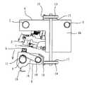
図1は中綴じ用ステープラの要部の斜視図であり、図2はその側面図である。この中綴じ用ステープラは、ステープル収納用マガジン1とこのマガジン1から供給されたステープルを被綴り用紙に向けて打ち出すドライバ2を含むマガジンユニット3を支持する上部ブラケット(ドライバ支持部)4と、打ち出されたステープルを折り曲げるクリンチャ5を支持する下部ブラケット(クリンチャ支持部)6とを上下に分離して配置したもので、通常は複写機やプリンタの画像形成装置の後段に設けられる用紙の後処理機としての用紙処理装置に設けられる。なお、ドライバ2はマガジン1の前端部に上下動可能に設けられ、被綴り用紙のクランプ時にはマガジン1とともに作動し、クランプ終了後はマガジンとは独立にステープルの打ち込み作動を行うように構成されている。[Embodiment 1]
FIG. 1 is a perspective view of a main part of the saddle stitching stapler, and FIG. 2 is a side view thereof. The saddle stitching stapler is driven out by an upper bracket (driver support portion) 4 that supports a
上部ブラケット4は上板部4aと側板部4bと底板部4cとから箱形に形成され、底板部4cにはドライバ2の駆動機構が設けられ、マガジンユニット3が上下方向に回動可能に設けられている。下部ブラケット6は上板部6aと側板部6bとから下向きに開口するコ字形に形成され、クリンチャ5は上板部6aに固定されている。マガジンユニット3とクリンチャ5とは互いに上下に対応する位置に配置されている。 The
上部ブラケット4と下部ブラケット6は両側移動機構を介して作動連結されている。すなわち、上部ブラケット4は、前後2本の平行な上部ガイドシャフト7、8にスライド移動可能に設けられ、下部ブラケット6も、前後2本の平行な下部ガイドシャフト9、10にスライド移動可能に設けられている。上部ガイドシャフト7、8と下部ガイドシャフト9、10も互いに平行に配置されている。 The
ところで上部ガイドシャフト7、8は、2本ともに上部ブラケット4の側板部4bにほとんど隙間なく嵌合している。これに対し、下部ガイドシャフトのうち後部シャフト10は下部ブラケット6の側板部6bに同様に嵌合しているが、前部シャフト9は側板部6bの前部の縦長貫通孔11に緩やかに挿通している。したがって、下部ブラケット6は、寸法差分だけ後部シャフト10を中心に上下方向に回動することができ、捩りコイルバネ19により常時は前側が図1、図2のように上方端位置にあるように付勢されている。 By the way, the two
また、上部ガイドシャフト7、8と下部ガイドシャフト9、10の後部には、上部ブラケット4と下部ブラケット6とをそれぞれ搬送する上部搬送ベルト13と下部搬送ベルト14が配置され、上部搬送ベルト13と下部搬送ベルト14にはそれぞれ上部ブラケット4と下部ブラケット6が固定されている。上部ブラケット4の上部には固定片15が形成され、この固定片15が上部搬送ベルト13にカシメによって固定されている。下部ブラケット6も同様にして後部に設けられた固定片16を介して下部搬送ベルト14に固定されている。さらに、上部搬送ベルト13と下部搬送ベルト14はそれぞれ同軸に設けられた同径のプーリ17に巻き懸けられている。これにより、プーリ17を回転させることにより、マガジンユニット3側の上部ブラケット4とクリンチャ5側の下部ブラケット6は左右方向に移動するとともに、上部ブラケット4と下部ブラケット6とが同時に同方向に同量だけ移動して常にドライバ2とクリンチャ5の上下の位置関係が同じに保たれるように構成されている。 Further, an
なお、下部ブラケット6は捩りコイルバネ19により前部が上方に傾いている。このとき固定片16も傾くが、下部搬送ベルト14は撓むので、固定片16の傾きに追従できる。 The
次に、下部ブラケット6の近傍には、下部ガイドシャフトと平行に綴りピッチを決めるロックプレート(位置決め手段)18が下部ブラケット6のスライド方向に沿って配置されている。下部ブラケット6の一方の側板6bの下端には位置決め部として突起20が形成され、ロックプレート18の上縁部にも位置決め部として所定間隔に位置決め溝21が形成されている。位置決め溝21の上端はやや幅広に形成されている。位置決め溝21は被綴り用紙のサイズや綴じ位置などに従って所定の位置に設けられている。 Next, in the vicinity of the
上記構成によれば、プーリ17を図示しない駆動機構によって駆動して上部ブラケット4と下部ブラケット6とを左右方向にほぼ同量だけ平行にスライド移動させて所定の位置に搬送した後、上部ブラケット4と下部ブラケット6との間に被綴り用紙(図示せず)を差し込んでドライバ駆動機構を作動させると、図3に示されるように、マガジンユニット3が下方に回動してマガジンユニット3とクリンチャ5との間に被綴り用紙をクランプし、さらにマガジンユニット3のドライバがステープルを被綴り用紙に打ち込み、ステープルの脚部の先端はクリンチャ5の溝に当って折り曲げられ、綴り作業が完了する。綴りが終了した後、プーリ17を回転させると、搬送ベルト13、14が移動し、上部ブラケット4と下部ブラケット6とが同時に同方向に同量だけ移動するので、所定の位置でプーリ17の回転を停止させてドライバ駆動機構を作動させることにより、同様にして綴り作業が行われる。 According to the above configuration, the
ところで、上述のように、ドライバ駆動機構が作動してマガジンユニット3が下方に回動してクランプ動作をしたとき、マガジンユニット3のクランプ力は被綴り用紙を介して下部ブラケット6に伝えられるから、クランプが開始されると、これに連動して、下部ブラケット6が後部シャフト10を中心に下方に回動し、一方の側板6bの突起20がロックプレート18の位置決め溝21に係合する。これにより、下部ブラケット6とクリンチャ5は正しく位置決めされ、左右に動くことはない。したがって、ステープルの脚部の先端がクリンチャ5に当った後、固定クリンチャ5の側とドライバ2の側との相対的な位置関係が保たれる。この結果、それほど搬送時の位置決め精度が備わっていない上部ブラケット4と下部ブラケット6との移動機構を用いた場合でも、綴り時における固定クリンチャ5とドライバ2との相対的な位置関係の精度を向上できるとともに、クリンチ負荷による左右方向への横ずれ耐力を格段に向上できて、綴り作動が確実に行われる。 By the way, as described above, when the driver driving mechanism is operated and the
上述のように、上記中綴じ用ステープラによれば、簡単な構造によって、綴り時にドライバ2側とクリンチャ5側とを正確に位置決めすることができる。したがって、ドライバ2と固定クリンチャ5の上下分離型ステープラであって両側移動機構を有するフィニッシャの製品化も十分に可能となる。 As described above, according to the saddle stitching stapler, the
また、綴りピッチを決める部品が少なく、品質が安定する。 Moreover, there are few parts which determine a spelling pitch, and quality is stabilized.
しかも、位置決めにはクランプ時の押圧力を直接に利用することができ、クリンチャ支持部を移動させるための特別の手段を必要とせず、構造を簡単にすることができる。 In addition, the pressing force at the time of clamping can be directly used for positioning, and no special means for moving the clincher support portion is required, and the structure can be simplified.
さらに、ロックプレート18を上部ブラケット4と下部ブラケット6のスライド方向に沿って配置し、位置決め部を構成する突起20は、ロックプレート18に所定の間隔で形成された構成であるから、容易に加工することができる。 Further, since the
また、ロックプレート18の位置決め溝21は仕様によって変更されるものであり、図の位置、数量に限定されない。また、位置決め部は突起と溝のように凸部と凹部とによって形成するのが好ましい。構造が簡単で、凹部の開口端を広げることによって凸部の係合を案内して確実に位置決めをすることができる。突起と溝は逆の位置に設けられていてもよい。以下の実施形態においても同様である。 Further, the
[実施形態2]
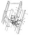
次に、図4は、下部ブラケット6が回動しないほかは、上述と同様の中綴じ用ステープラに別の形態の位置決め機構を設けた例の要部の斜視図で、下部ブラケット6の上面部に位置決め部としてロックピン22が上下に移動可能に設けられている。ロックピン22は圧縮バネ23により常時上方に付勢され、上方から押し込まれたときは、下部ブラケット6の上面部を貫通して下方に突出して下部ガイドシャフトの前部シャフト9の上面に当るように構成されている。前部シャフト9は位置決め手段として構成され、その上面には所定間隔に位置決め部として位置決め凹部24が形成されている。位置決め凹部24の上端は外に広がって開口端が広くなるように形成されている。本実施形態において、位置決め凹部24は一例として貫通孔として形成されている。[Embodiment 2]
Next, FIG. 4 is a perspective view of a main part of an example in which another type of positioning mechanism is provided on the saddle stitching stapler similar to the above except that the
なお、上部ブラケット4のロックピン22に対応する位置には押圧部25が形成されている。 A
上記構成によれば、ドライバ駆動機構とクリンチャ5との間に被綴り用紙を差し込んでドライバ駆動機構を作動させると、図5に示されるように、マガジンユニット3が下方に回動してクランプ動作をする。このとき、上部ブラケット4の押圧部25も被綴り用紙を押圧する。マガジンユニット3のクランプ力は被綴り用紙を介して下部ブラケット6に伝えられるから、クランプが開始されると、これに連動して、上部ブラケット4の押圧部25が被綴り用紙を介して下部ブラケット6のロックピン22を圧縮バネ23に抗して押し下げるので、図6のようにロックピン22は下方に移動して前部シャフト9の位置決め用凹部24に係合する。これにより、下部ブラケット6とクリンチャ5は正しく位置決めされ、左右に動くことはない。したがって、ステープルの脚部の先端がクリンチャ5に当った後、固定クリンチャ5とドライバ2の中心が自動調芯され、横ずれが発生することなく、綴り作動が確実に行われる。 According to the above configuration, when the driver driving mechanism is operated by inserting the stapled paper between the driver driving mechanism and the
上述の構成の中綴じ用ステープラによれば、簡単な構造によって、綴り時にクリンチャ5側だけでなくドライバ2側も正確に位置決めすることができる。 According to the saddle stitch stapler having the above-described configuration, not only the
なお、位置決めはロックピンのようなピン形状でなく、ボール形状でもよい。 The positioning may be a ball shape instead of a pin shape like a lock pin.
[実施形態3]
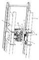
次に、図7及び図8は、図1に示したものと同様の中綴じ用ステープラにさらに別の形態の位置決め機構を設けた例の要部の斜視図で、下部ブラケット6とロックプレート18とには図1に示したものと同じ位置決め機構が設けられているが、さらに上部ブラケット4とその上部近傍に上部ガイドシャフト7、8と平行に設けられた上部ロックプレート(位置決め手段)25とに位置決め機構が設けられている。[Embodiment 3]
Next, FIGS. 7 and 8 are perspective views of the main part of an example in which a positioning mechanism of another form is provided on the saddle stitching stapler similar to that shown in FIG. 1, and the
すなわち、上部ブラケット4の一方の側板4bの上端には位置決め部として突起20が形成され、上部ロックプレートの下縁部には位置決め部として所定間隔に位置決め溝21が形成されている。位置決め溝21の下端はやや幅広に形成されている。なお、上部ガイドシャフトの後部シャフト8は上部ブラケット4の側板部4bに嵌合しているが、前部シャフト7は側板部4bの前部の縦長貫通孔26に緩やかに挿通している。したがって、上部ブラケット4は、寸法差分だけ後部シャフト8を中心に上下方向に回動することができる。また、上部ブラケット4の側板部4bの内側に屈曲する屈曲部27と上部ガイドシャフトに嵌合したガイドブロック28との間には圧縮バネ30が配置され、上部ブラケット4は常時下方に回動するように付勢されている。同様に、下部ブラケット6は捩りコイルバネ19により常時は上方に位置するように付勢されている。ガイドブロック28の上部には凸部31が形成され、上部ブラケット4の開口部32に嵌合して、上部ブラケット4とともに上部ガイドシャフト7の軸方向にスライドするように構成されている。 That is, a
上記構成によれば、ドライバ駆動機構とクリンチャ5との間に被綴り用紙を差し込んでドライバ駆動機構を作動させると、マガジンユニット3が下方に回動してクランプ動作をする。このとき、上部ブラケット4の押圧部も被綴り用紙を押圧する。マガジンユニット3のクランプ力は被綴り用紙を介して下部ブラケット6に伝えられるから、クランプが開始されると、これに連動して、図9に示されるように、下部ブラケット6が後部シャフト10を中心に下方に回動し、一方の側板6bの突起20がロックプレート25の位置決め溝21に係合する。 According to the above configuration, when the binding paper is inserted between the driver driving mechanism and the
ところで、下部ブラケット6が下方に回動して停止しても、マガジンユニット3は上部ブラケット4に対してさらに下方に回動して十分にクランプするように構成されているから、マガジンユニット3が回動できなくなると、さらに回動し続ける部分は、上部ブラケット4が圧縮バネ30に抗して後部シャフト8を中心に上方に回動し、さらにはステープラ内部に設けられた圧縮バネ(図示せず)が撓むことで吸収される。上部ブラケット4が上方に回動すると、その上縁の突起20は上部ロックプレート25の位置決め溝21に係合する。 By the way, even if the
なお、上部ブラケット4と上部ロックプレート25とが係合するタイミングと、下部ブラケット6と下部ロックプレート18とが係合するタイミングとは、何れの係合するタイミングが先になってもかまわず、コイルバネ19、圧縮バネ30のバネ荷重によって調整できる。 It should be noted that the timing at which the
このように、クランプ作動に連動して上部ブラケット4と上部ロックプレート25及び下部ブラケット6と下部ロックプレート18は、それぞれ正しく位置決めされ、左右に動くことはない。したがって、ステープルの脚部の先端がクリンチャ5に当った後、固定クリンチャ5の側とドライバ2の側との相対的な位置関係が保たれる。この結果、それほど搬送時の位置決め精度が備わっていない上部ブラケット4と下部ブラケット6との移動機構を用いた場合でも、綴り時における固定クリンチャ5とドライバ2との相対的な位置関係の精度を向上できるとともに、クリンチ負荷による左右方向への横ずれ耐力を格段に向上できて、綴り作動が確実に行われる。 In this way, the
上述の構成の中綴じ用ステープラによっても、簡単な構造によって、綴り時にドライバ2側とクリンチャ5側とを正確に位置決めすることができる。 Also with the saddle stitch stapler having the above-described configuration, the
[実施形態4]
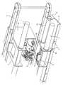
次に、図10は、上述と同じ中綴じ用ステープラにさらに他の形態の位置決め機構を設けた例の要部の斜視図で、位置決め部として、下部ブラケット6の側板部6bの下端には位置決め部として突起20が形成され、ロックプレート(位置決め手段)18の上面部には位置決め部として位置決め溝21が形成されている。そして、ロックプレート18の両側後端に形成された屈曲片29は下部ガイドシャフトの後部シャフト10に上下に回動可能に支持されている。ロックプレート18は適宜手段によって、ステープラの左右移動終了後、綴り動作前のクランプ作動に連動して上方に回動するように構成されている。[Embodiment 4]
Next, FIG. 10 is a perspective view of a main part of an example in which the same saddle stitching stapler as described above is provided with a positioning mechanism of another form, and positioning is performed at the lower end of the
上記構成によれば、クランプ動作に連動して、ロックプレート18が回動し、ロックプレート18の位置決め溝21一方の側板6bの突起20がロックプレート18の位置決め溝21に係合する。これにより、下部ブラケット6とクリンチャ5は正しく位置決めされる。 According to the above configuration, the
ロックプレート18の回動はクランプ作動に連動して行われればよく、駆動機構は限定されない。リンク・カム機構、ソレノイド機構等、電気的あるいは機械的機構によってもよい。 The
なお、図11は位置決め手段であるロックプレート18の駆動手段の一形態を示すもので、ロックプレート18の後方に駆動片33を延長し、駆動片33の先端を上部ブラケット4に設けられたマガジンユニット3の下方に配置する。このとき、上部ブラケット4と駆動片33の先端との間には被綴り用紙が通る間口を確保する。なお、マガジンユニット3はステープラ本体34に対して上下に移動可能に配置されている。 FIG. 11 shows one form of drive means for the
上記構成によれば、マガジンユニット3とクリンチャ5との間に被綴り用紙を差し込んでドライバ駆動機構を作動させると、マガジンユニット3が下方に移動してクランプ動作をする。これに連動してヘッド部に設けられたマガジンユニット3の下面がロックプレートの駆動片33の先端を押し下げるので、ロックプレート18の前部は後部シャフト20を中心に上方に回動し、ロックプレート18の位置決め溝21に下部ブラケット6の一方の側板部6bの突起20が係合し、固定クリンチャ5の側とドライバ2の側との相対的な位置関係が保たれる。この結果、それほど搬送時の位置決め精度が備わっていない上部ブラケット4と下部ブラケット6との移動機構を用いた場合でも、綴り時における固定クリンチャ5とドライバ2との相対的な位置関係の精度が向上できるとともに、クリンチ負荷による左右方向への横ずれ耐力を格段に向上できる。 According to the above configuration, when a sheet to be bound is inserted between the
したがって、上述の構成によっても、簡単な構造によって、綴り時にドライバ側とクリンチャ5側とを正確に位置決めすることができる。 Therefore, even with the above-described configuration, the driver side and the
1 マガジン
4 上部ブラケット(ドライバ支持部)
5 クリンチャ
6 下部ブラケット(クリンチャ支持部)
18 (下部)ロックプレート(位置決め手段)
20 突起(位置決め部)
21 位置決め溝(位置決め部)
22 ロックピン(位置決め部)
24 位置決め凹部(位置決め部)
25 上部ロックプレート(位置決め手段)1
5
18 (Lower) Lock plate (positioning means)
20 Protrusion (positioning part)
21 Positioning groove (positioning part)
22 Lock pin (positioning part)
24 Positioning recess (positioning part)
25 Upper lock plate (positioning means)
Claims (6)
Translated fromJapanese上記クリンチャ支持部又はドライバ支持部の近傍に位置決め手段を設け、上記クランプ作動に連動させて上記クリンチャ支持部又はドライバ支持部と位置決め手段とにそれぞれ設けた位置決め部同士を係合させる
ことを特徴とする中綴じ用ステープラ。A driver support unit that supports a driver drive mechanism that drives staples supplied from a staple storage magazine toward the paper to be bound, and a clincher support unit that fixes a clincher that folds the staples that are placed are separated vertically. In addition, in the saddle stitching stapler which is provided so that both the support portions can be slid in parallel in substantially the same amount in the left-right direction, and the binding operation is performed after clamping the sheet to be bound between the both support portions.
Positioning means is provided in the vicinity of the clincher support part or driver support part, and the positioning parts provided in the clincher support part or driver support part and positioning means are engaged with each other in conjunction with the clamp operation. Saddle stitching stapler.
Priority Applications (4)
| Application Number | Priority Date | Filing Date | Title |
|---|---|---|---|
| JP2009291554AJP2011131444A (en) | 2009-12-23 | 2009-12-23 | Stapler for saddle stitching |
| EP10015205.7AEP2338654A3 (en) | 2009-12-23 | 2010-12-01 | Stapler |
| US12/964,979US8523039B2 (en) | 2009-12-23 | 2010-12-10 | Stapler |
| CN2010106089951ACN102107795A (en) | 2009-12-23 | 2010-12-23 | Stapler |
Applications Claiming Priority (1)
| Application Number | Priority Date | Filing Date | Title |
|---|---|---|---|
| JP2009291554AJP2011131444A (en) | 2009-12-23 | 2009-12-23 | Stapler for saddle stitching |
Publications (1)
| Publication Number | Publication Date |
|---|---|
| JP2011131444Atrue JP2011131444A (en) | 2011-07-07 |
Family
ID=43797621
Family Applications (1)
| Application Number | Title | Priority Date | Filing Date |
|---|---|---|---|
| JP2009291554APendingJP2011131444A (en) | 2009-12-23 | 2009-12-23 | Stapler for saddle stitching |
Country Status (4)
| Country | Link |
|---|---|
| US (1) | US8523039B2 (en) |
| EP (1) | EP2338654A3 (en) |
| JP (1) | JP2011131444A (en) |
| CN (1) | CN102107795A (en) |
Families Citing this family (4)
| Publication number | Priority date | Publication date | Assignee | Title |
|---|---|---|---|---|
| JP6102890B2 (en)* | 2014-11-11 | 2017-03-29 | コニカミノルタ株式会社 | Paper processing apparatus and image forming system |
| WO2017094040A1 (en)* | 2015-11-30 | 2017-06-08 | 内田洋行グローバルリミテッド | Stapling device |
| CN108312733B (en)* | 2018-03-26 | 2023-05-05 | 西南交通大学 | A heavy duty stapler |
| CN108515784B (en)* | 2018-04-27 | 2024-10-29 | 得力集团有限公司 | Paper pressing table locking mechanism of bookbinding machine |
Citations (1)
| Publication number | Priority date | Publication date | Assignee | Title |
|---|---|---|---|---|
| JPH06325547A (en)* | 1993-05-13 | 1994-11-25 | Sanyo Electric Co Ltd | Recorder/reproducer |
Family Cites Families (11)
| Publication number | Priority date | Publication date | Assignee | Title |
|---|---|---|---|---|
| JPH07157181A (en)* | 1993-12-09 | 1995-06-20 | Fuji Xerox Co Ltd | Post-processing device for recording sheet |
| JP3473233B2 (en)* | 1995-11-16 | 2003-12-02 | ニスカ株式会社 | Stapler |
| JPH09325547A (en)* | 1996-06-03 | 1997-12-16 | Fuji Xerox Co Ltd | Postprocessor |
| USH1842H (en)* | 1998-01-09 | 2000-03-07 | Xerox Corporation | Pass through repositionable stapler-compiler system with clincher alignment system |
| JP2000084903A (en)* | 1998-09-11 | 2000-03-28 | Minolta Co Ltd | Stapling device |
| JP2000185868A (en) | 1998-12-21 | 2000-07-04 | Konica Corp | Sheet post-processing device and image forming device |
| US6641024B2 (en)* | 2000-02-08 | 2003-11-04 | Nisca Corporation | Stapling device |
| JP4748293B2 (en)* | 2001-09-11 | 2011-08-17 | マックス株式会社 | Built-in stapler |
| DE60238362D1 (en)* | 2001-11-29 | 2010-12-30 | Max Co Ltd | Electric stapler |
| JP4110855B2 (en)* | 2002-06-28 | 2008-07-02 | マックス株式会社 | Electric stapler moving mechanism |
| JP4823646B2 (en)* | 2005-10-31 | 2011-11-24 | 京セラミタ株式会社 | Paper post-processing device |
- 2009
- 2009-12-23JPJP2009291554Apatent/JP2011131444A/enactivePending
- 2010
- 2010-12-01EPEP10015205.7Apatent/EP2338654A3/ennot_activeWithdrawn
- 2010-12-10USUS12/964,979patent/US8523039B2/ennot_activeExpired - Fee Related
- 2010-12-23CNCN2010106089951Apatent/CN102107795A/enactivePending
Patent Citations (1)
| Publication number | Priority date | Publication date | Assignee | Title |
|---|---|---|---|---|
| JPH06325547A (en)* | 1993-05-13 | 1994-11-25 | Sanyo Electric Co Ltd | Recorder/reproducer |
Also Published As
| Publication number | Publication date |
|---|---|
| EP2338654A3 (en) | 2013-05-22 |
| US8523039B2 (en) | 2013-09-03 |
| EP2338654A2 (en) | 2011-06-29 |
| CN102107795A (en) | 2011-06-29 |
| US20110147431A1 (en) | 2011-06-23 |
Similar Documents
| Publication | Publication Date | Title |
|---|---|---|
| JP5359694B2 (en) | Stapler clincher mechanism | |
| US8146906B2 (en) | Sheet processing apparatus | |
| JP2011131444A (en) | Stapler for saddle stitching | |
| JP4232371B2 (en) | stapler | |
| JP5333083B2 (en) | Electric stapler | |
| JP5262299B2 (en) | Clinch positioning mechanism in stapler | |
| JP5211830B2 (en) | Staple feeding mechanism in stapler | |
| EP1177869B1 (en) | Electric stapler | |
| US9162368B2 (en) | Electric stapler | |
| KR100662925B1 (en) | Built-in Stapler | |
| US10695942B2 (en) | Stapler | |
| WO2005068135A1 (en) | Stapler | |
| JP4420208B2 (en) | Stapler clincher device | |
| US20040069830A1 (en) | Stapler apparatus | |
| JP5428842B2 (en) | Saddle binding stapler and its assembly jig | |
| JP4304971B2 (en) | Paper thickness adjustment mechanism in an electric stapler | |
| JP5708352B2 (en) | Saddle stitch stapler | |
| JP2024092214A (en) | Stapler | |
| JP2011131307A5 (en) | ||
| JP2011183760A (en) | Alignment jig of stapler | |
| JP2003165104A (en) | Electromotive stapler | |
| JP2005081526A (en) | Clincher device for stapler | |
| JP2003211408A (en) | Electromotive stapler | |
| JP2013136441A (en) | Sheet processing apparatus and image forming system | |
| JP2007167990A (en) | Stapler |
Legal Events
| Date | Code | Title | Description |
|---|---|---|---|
| A621 | Written request for application examination | Free format text:JAPANESE INTERMEDIATE CODE: A621 Effective date:20120824 | |
| A977 | Report on retrieval | Free format text:JAPANESE INTERMEDIATE CODE: A971007 Effective date:20130930 | |
| A131 | Notification of reasons for refusal | Free format text:JAPANESE INTERMEDIATE CODE: A131 Effective date:20131001 | |
| A02 | Decision of refusal | Free format text:JAPANESE INTERMEDIATE CODE: A02 Effective date:20140218 |