Movatterモバイル変換


[0]ホーム

URL:


JP2011131353A - Flat clinch type stapler - Google Patents

Flat clinch type stapler
Download PDF

Info

Publication number
JP2011131353A
JP2011131353AJP2009294570AJP2009294570AJP2011131353AJP 2011131353 AJP2011131353 AJP 2011131353AJP 2009294570 AJP2009294570 AJP 2009294570AJP 2009294570 AJP2009294570 AJP 2009294570AJP 2011131353 AJP2011131353 AJP 2011131353A
Authority
JP
Japan
Prior art keywords
contact surface
anvil
paper
magazine
spelling
Prior art date
Legal status (The legal status is an assumption and is not a legal conclusion. Google has not performed a legal analysis and makes no representation as to the accuracy of the status listed.)
Granted
Application number
JP2009294570A
Other languages
Japanese (ja)
Other versions
JP5521215B2 (en
Inventor
Masaru Shinohara
勝 篠原
Current Assignee (The listed assignees may be inaccurate. Google has not performed a legal analysis and makes no representation or warranty as to the accuracy of the list.)
Kokuyo Co Ltd
Original Assignee
Kokuyo Co Ltd
Priority date (The priority date is an assumption and is not a legal conclusion. Google has not performed a legal analysis and makes no representation as to the accuracy of the date listed.)
Filing date
Publication date
Application filed by Kokuyo Co LtdfiledCriticalKokuyo Co Ltd
Priority to JP2009294570ApriorityCriticalpatent/JP5521215B2/en
Priority to PCT/JP2010/073080prioritypatent/WO2011078202A1/en
Priority to CN2010800591139Aprioritypatent/CN102666026A/en
Publication of JP2011131353ApublicationCriticalpatent/JP2011131353A/en
Application grantedgrantedCritical
Publication of JP5521215B2publicationCriticalpatent/JP5521215B2/en
Activelegal-statusCriticalCurrent
Anticipated expirationlegal-statusCritical

Links

Images

Classifications

Landscapes

Abstract

Translated fromJapanese

【課題】つづり針を座屈等を招くことなくフラットな状態に折曲げて綴ることができるフラットクリンチ型ステープラを提供する。
【解決手段】綴るべき用紙を添えるための用紙テーブル3と、この用紙テーブル3に対向配置されつづり針Nを保持するマガジン5と、このマガジン5に保持されたつづり針Nを用紙テーブル3方向に押し出す押刃7と、この押刃7により押し出され前記用紙Pを貫通したつづり針Nの貫通端部N1を折曲用当接面9または成型用当接面11により折り曲げるためのアンビル13と、このアンビル13による折曲げ動作時に前記つづり針Nを前記折曲用当接面に係わり合わせた後に前記成型用当接面11に係わり合わせる当接面切換機構とを具備してなる。
【選択図】図2
The present invention provides a flat clinch type stapler that can bend and spell a spelling needle in a flat state without causing buckling or the like.
A paper table 3 for attaching a paper to be bound, a magazine 5 that is arranged opposite to the paper table 3 and holds a spelling needle N, and a spelling needle N held in the magazine 5 in the direction of the paper table 3 are provided. A pushing blade 7 to be pushed out, and an anvil 13 for bending the penetrating end N1 of the spelling needle N pushed out by the pushing blade 7 and penetrating the paper P by the folding contact surface 9 or the molding contact surface 11; A contact surface switching mechanism for engaging the spelling needle N with the bending contact surface 11 and then engaging with the molding contact surface 11 during the bending operation by the anvil 13 is provided.
[Selection] Figure 2

Description

Translated fromJapanese

本発明は、用紙を綴じるためのフラットクリンチ型のステープラに関するものである。  The present invention relates to a flat clinch type stapler for binding sheets.

従来、この種のステープラとして、綴るべき用紙を添えるための用紙テーブルと、この用紙テーブルに対向配置されつづり針を保持するマガジンと、このマガジンに保持されたつづり針を用紙テーブル方向に押し出す押刃と、この押刃により押し出され前記用紙を貫通したつづり針の貫通端部を折り曲げるためのアンビルとを具備してなるものが知られている(例えば、特許文献1を参照)。  Conventionally, as this type of stapler, a paper table for attaching paper to be bound, a magazine for holding a spelling needle arranged opposite to the paper table, and a pressing blade for pushing the spelling needle held in the magazine toward the paper table And an anvil for bending a penetrating end portion of a spelling needle that is pushed out by the pressing blade and penetrates the paper (see, for example, Patent Document 1).

ところが従来のものは、固定されたアンビルの先端につづり針の貫通端部を案内して折曲げるための当接面を形成している。この当接面は、前記つづり針の先端を内側に案内する方向に用紙に対して傾斜したものである。そのため、折曲げ最終段階において、前記つづり針の貫通端部における根本部分を十分に用紙方向に押しつけることが困難であり、その根本部分が若干用紙から離れる方向に膨らんだ状態で綴りが完了することになってしまうという不具合がある。  However, the conventional one forms a contact surface for guiding and bending the penetrating end of the spelling needle at the tip of the fixed anvil. This abutting surface is inclined with respect to the paper in the direction in which the tip of the spelling needle is guided inward. Therefore, at the final stage of bending, it is difficult to sufficiently press the root portion at the penetrating end portion of the spelling needle in the paper direction, and the spelling is completed with the root portion slightly swollen away from the paper. There is a problem that it becomes.

このような不具合は、前記当接面の傾斜をゆるく設定しておくことにより緩和することも可能であるが、このようにすると、折曲げ初期につづり針の先端を円滑に内方に案内することが難しくなり、つづり針の貫通端部が座屈するという問題を招きやすい、というジレンマがある。  Such a problem can be alleviated by setting the inclination of the contact surface to be loose, but in this case, the tip of the spelling needle is smoothly guided inward at the initial stage of bending. There is a dilemma that it becomes difficult to cause a problem that the penetrating end of the spelling needle buckles.

特公平6−92075号公報Japanese Patent Publication No. 6-92075

本発明は、以上のような課題を解消し、つづり針を座屈等を招くことなくフラットな状態に折曲げて綴ることができるフラットクリンチ型ステープラを提供することを目的とする。  An object of the present invention is to provide a flat clinch-type stapler that can solve the above-described problems and can bend and spell a spelling needle in a flat state without causing buckling or the like.

本発明は、以上のような課題を解決するために、次のような構成を採用したものである。すなわち、本発明に係るフラットクリンチ型ステープラは、綴るべき用紙を添えるための用紙テーブルと、この用紙テーブルに対向配置されつづり針を保持するマガジンと、このマガジンに保持されたつづり針を用紙テーブル方向に押し出す押刃と、この押刃により押し出され前記用紙を貫通したつづり針の貫通端部を折曲用当接面または成型用当接面により折り曲げるためのアンビルと、このアンビルによる折曲げ動作時に前記つづり針を前記折曲用当接面に係わり合わせた後に前記成型用当接面に係わり合わせる当接面切換機構とを具備してなることを特徴とする。  The present invention employs the following configuration in order to solve the above-described problems. That is, the flat clinch type stapler according to the present invention includes a paper table for attaching paper to be bound, a magazine that holds the spelling needles arranged opposite to the paper table, and the spelling needles held in the magazine in the paper table direction. An anvil for folding the penetrating end portion of the spelling needle pushed out by the push blade and penetrating the paper by the folding contact surface or the molding contact surface, and during the folding operation by the anvil And a contact surface switching mechanism for engaging the spelling needle with the bending contact surface and then engaging with the molding contact surface.

ここで「用紙」は、シート状のもの一般を指すものとし、紙製のもの、プラスチック製のもの、布製のもの等を含むものとする。  Here, the “paper” refers to a sheet-like material in general, and includes a paper material, a plastic material, a cloth material, and the like.

このようなものであれば、つづり針を座屈等を招くことなくフラットな状態に折曲げて綴ることができる。すなわち、折曲用当接面によってつづり針の先端を案内することができるため、つづり針の貫通端部の座屈を防ぐために当接面の傾斜をゆるく設定する必要がなくなるとともに、折曲用当接面に係わり合った後のつづり針が成型用当接面に係わり合わされるので、折曲げ最終段階において、前記つづり針の貫通端部における根本部分を十分に用紙方向に押しつけることができる。そのため、その根本部分が若干用紙から離れる方向に膨らんだ状態で綴りが完了する不具合が解消される。したがって、本発明によれば、従来生じていたジレンマを一挙に解消し、用紙を綴る際の一連の動作によって、つづり針を座屈等を招くことなくフラットな状態に折曲げて綴ることができる。  If it is such, it can be spelled by bending the spelling needle into a flat state without causing buckling or the like. That is, since the tip of the spelling needle can be guided by the bending contact surface, it is not necessary to set the inclination of the contact surface loosely in order to prevent buckling of the penetrating end of the spelling needle. Since the spelling needle after being engaged with the contact surface is engaged with the molding contact surface, the root portion at the penetrating end portion of the spelling needle can be sufficiently pressed in the paper direction at the final folding stage. For this reason, the problem that the spelling is completed in a state in which the root portion is slightly swollen away from the sheet is solved. Therefore, according to the present invention, the conventional dilemma can be eliminated at once, and the spelling needle can be folded and flattened without causing buckling or the like by a series of operations when binding the paper. .

アンビルの好ましい一態様としては、それぞれ前記折曲用当接面及び成型用当接面を有した対をなすアンビルメンバを具備してなるものであり、当接面切換機構は、前記アンビルメンバを相対的に移動させることによりつづり針に係り合う当接面を折曲用当接面から成型用当接面に切換えるように構成したものを挙げることができる。  As a preferred embodiment of the anvil, the anvil member includes a pair of an anvil member each having the bending contact surface and the molding contact surface, and the contact surface switching mechanism includes the anvil member. A structure in which the contact surface engaged with the spelling needle is switched from the contact surface for bending to the contact surface for molding can be given.

より具体的には、アンビルが、アンビルベースに前記両アンビルメンバを回動可能に支持させたものであり、前記当接面切換機構が、前記両アンビルメンバを接離する方向に回動付勢し得るように構成したものが、好ましい一例として考えられる。  More specifically, the anvil has the anvil base rotatably supported by the two anvil members, and the abutment surface switching mechanism urges the two anvil members to contact and separate from each other. What was comprised so that it can do is considered as a preferable example.

当接面切換機構は、前記用紙テーブルの動きを利用して前記アンビルメンバを駆動するようにしてもよく、この場合の好適な態様としては、当接面切換機構が、前記アンビルメンバの外側面に設けられたカム面と、これらカム面に摺接すべく用紙テーブルの側壁に形成され当該用紙テーブルの沈み込み動作時に前記カム面を押圧して前記両アンビルメンバを接近する方向に付勢する押圧子と、前記両アンビルメンバを離間する方向に付勢する弾性部材とを具備してなるものを挙げることができる。  The contact surface switching mechanism may drive the anvil member using the movement of the paper table. In this case, as a preferred aspect, the contact surface switching mechanism is configured such that the contact surface switching mechanism has an outer surface of the anvil member. The cam surfaces are formed on the side walls of the paper table so as to be in sliding contact with the cam surfaces, and the cam surfaces are pressed to urge both the anvil members toward each other when the paper table is depressed. Examples thereof include a pressing element and an elastic member that urges the two anvil members in the direction of separating them.

各アンビルメンバは、基端をアンビルベースに軸着するとともに、前記押刃に対向する先端に折曲用当接面及び成型用当接面を連続して形成したものが好ましい。  Each anvil member preferably has a proximal end pivotally attached to the anvil base and a bending contact surface and a molding contact surface formed continuously at the distal end facing the pressing blade.

折曲用当接面は、前記アンビルメンバが離間した位置で前記つづり針の先端を内側に案内する方向に用紙に対して傾斜したものであり、成型用当接面は、前記アンビルメンバが接近した位置で用紙と平行となるものであるのが、好ましい一態様として挙げられる。  The folding contact surface is inclined with respect to the sheet in a direction in which the tip of the spelling needle is guided inwardly at a position where the anvil member is separated, and the molding contact surface is approached by the anvil member. A preferred embodiment is that the sheet is parallel to the sheet at the position.

以上のように、本発明は、つづり針の貫通端部を折り曲げるアンビルが、折曲げ動作の最終段階でつづり針の貫通端部をフラットな状態に成形する成型用当接面を備えているものである。  As described above, according to the present invention, the anvil for folding the penetrating end of the spelling needle has a molding contact surface that molds the penetrating end of the spelling needle into a flat state at the final stage of the bending operation. It is.

本発明は、以上のような構成であるから、つづり針を座屈等を招くことなくフラットな状態に折曲げて綴ることができるフラットクリンチ型ステープラを提供することができる。  Since this invention is the above structures, it can provide the flat clinch type stapler which can bend and spell a spelling needle in a flat state without causing buckling etc.

本発明の一実施形態を示す側面図。The side view which shows one Embodiment of this invention.同実施形態を左右方向中央で切断した側断面図。The sectional side view which cut | disconnected the embodiment at the center of the left-right direction.同実施形態の一部を示す分解斜視図。The disassembled perspective view which shows a part of the embodiment.同実施形態の一部を示す分解斜視図。The disassembled perspective view which shows a part of the embodiment.同実施形態の一部を省略して要部を拡大して示す分解斜視図。The disassembled perspective view which abbreviate | omits a part of the embodiment and shows an enlarged principal part.同実施形態の一部を省略して側面を示す動作説明図。Operation | movement explanatory drawing which abbreviate | omits a part of the embodiment and shows a side surface.同実施形態の一部を省略して側面を示す動作説明図。Operation | movement explanatory drawing which abbreviate | omits a part of the embodiment and shows a side surface.同実施形態の一部を省略して側面を示す動作説明図。Operation | movement explanatory drawing which abbreviate | omits a part of the embodiment and shows a side surface.同実施形態の要部を拡大して示す動作説明図。Operation | movement explanatory drawing which expands and shows the principal part of the embodiment.同実施形態の要部を拡大して示す動作説明図。Operation | movement explanatory drawing which expands and shows the principal part of the embodiment.同実施形態の要部を拡大して示す動作説明図。Operation | movement explanatory drawing which expands and shows the principal part of the embodiment.同実施形態の要部を拡大して示す動作説明図。Operation | movement explanatory drawing which expands and shows the principal part of the embodiment.同実施形態の要部を拡大して示す動作説明図。Operation | movement explanatory drawing which expands and shows the principal part of the embodiment.同実施形態の要部を拡大して示す動作説明図。Operation | movement explanatory drawing which expands and shows the principal part of the embodiment.同実施形態の要部を拡大して示す動作説明図。Operation | movement explanatory drawing which expands and shows the principal part of the embodiment.

以下、本発明の一実施形態について図面を参照しながら説明する。  Hereinafter, an embodiment of the present invention will be described with reference to the drawings.

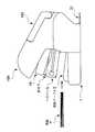
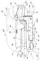
このフラットクリンチ型ステープラは、図1ないし図15に示すように、ベース1と、このベース1に枢着され綴るべき用紙Pを添えるための用紙テーブル3と、この用紙テーブル3に対向配置されつづり針Nを保持するマガジン5と、このマガジン5に保持されたつづり針Nを用紙テーブル3方向に押し出す押刃7と、この押刃7により押し出され前記用紙Pを貫通したつづり針Nの貫通端部N1を折曲用当接面9または成型用当接面11により折り曲げるためのアンビル13と、このアンビル13による折曲げ動作時に前記つづり針Nを前記折曲用当接面9に係わり合わせた後に前記成型用当接面11に係わり合わせる当接面切換機構15とを具備してなる。  As shown in FIGS. 1 to 15, the flat clinch type stapler includes abase 1, a paper table 3 that is pivotally attached to thebase 1, and a paper table 3 that is to be bound, and is disposed so as to face the paper table 3. Amagazine 5 that holds the needle N, apressing blade 7 that pushes the spelling needle N held in themagazine 5 in the direction of the paper table 3, and a penetrating end of the spelling needle N that is pushed out by thepressing blade 7 and penetrates the paper P Ananvil 13 for bending the portion N1 by thebending contact surface 9 or themolding contact surface 11, and the spelling needle N is engaged with thebending contact surface 9 during the bending operation by theanvil 13. And a contactsurface switching mechanism 15 to be engaged with themolding contact surface 11 later.

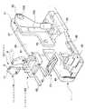
ベース1は、図1ないし図3及び図5に示すように、合成樹脂により一部品で成形されたもので、後端側に形成された内側壁17の後側に設けられ前記マガジン5及び後述する押刃ベース19の基端部21を枢支する共通枢着部23と、前記内側壁17の前側に設けられ前記用紙テーブル3の基端部24を枢支するテーブル枢着部25と、前記内側壁17の外側に形成された外側壁26に設けられ後述するハンドル169を枢支するハンドル枢着部27と、前記アンビル13を取付けるためのアンビル取付部29とを具備してなる。ベース1の後端部には、金属製のリムーバ31が取り付けられている。  As shown in FIGS. 1 to 3 and 5, thebase 1 is formed of one piece of synthetic resin and is provided on the rear side of theinner wall 17 formed on the rear end side. Acommon pivot part 23 pivotally supporting thebase end part 21 of thepressing blade base 19; atable pivoting part 25 provided on the front side of theinner wall 17 and pivotally supporting thebase end part 24 of the paper table 3; Ahandle pivoting portion 27 is provided on anouter wall 26 formed outside theinner wall 17 and pivotally supports ahandle 169 described later, and ananvil mounting portion 29 for mounting theanvil 13. Ametal remover 31 is attached to the rear end of thebase 1.

用紙テーブル3は、図1ないし図3及び図5ないし図15に示すように、板金素材を折曲げ加工して作られた金属製のもので、基端部24を前記ベース1のテーブル枢着部25に枢着してなる下方に開放した箱形のもので、前記アンビル13に対応する部位に窓33を設けている。この用紙テーブル3は、後端がベース1に設けた後ストッパ35に当接する用紙固定位置(F)の近傍から、前記窓33がアンビル13の先端69に近接する沈み込み位置(D)までの間で上下方向に回動し得るようになっており、ベース1に保持された弾性部材たる用紙テーブルばね37により用紙固定位置(F)方向に付勢されている。この用紙テーブル3の両側壁39にはロック用当接部41が形成されており、このロック用当接部41は、当該当接部41とともに後述するテーブルロック機構43を構成するロックサポート45に当接するようになっている。  As shown in FIGS. 1 to 3 and FIGS. 5 to 15, the paper table 3 is made of metal made by bending a sheet metal material, and thebase end portion 24 is pivotally attached to the table of thebase 1. A box-shaped box that is pivotally attached to theportion 25 and opens downward, and awindow 33 is provided at a portion corresponding to theanvil 13. This paper table 3 has a rear end from the vicinity of the paper fixing position (F) where the rear end abuts on therear stopper 35 provided on thebase 1 to the submerged position (D) where thewindow 33 is close to thefront end 69 of theanvil 13. It can be rotated in the vertical direction, and is biased in the paper fixing position (F) direction by apaper table spring 37 which is an elastic member held by thebase 1. Lockingcontact portions 41 are formed on bothside walls 39 of the paper table 3, and thelocking contact portions 41 together with alock support 45 constituting atable lock mechanism 43 described later together with thecontact portions 41. It comes to contact.

ロックサポート45は、図2、図3及び図6ないし図8に示すように、下面に突設した脚部47をベース1のレール部49に前後方向にスライド可能に係合させたサポート本体51を主体に構成されたもので、前記ロック用当接部41の下方への移動を阻止するロック位置(L)と、前記ロック用当接部41の下方への移動を許容する退避位置(S)との間で進退し得るようになっている。サポート本体51の後には、ばね収容部57が設けられており、このばね収容部57内に該サポート本体51をロック位置(L)方向へ付勢する弾性部材たるロックサポートばね53が配されている。また、前記ばね収容部57の両側には、後方に延出して後端部が上方に起立するサポートアーム59が一体に形成されている。  As shown in FIGS. 2, 3, and 6 to 8, thelock support 45 includes asupport body 51 in which aleg portion 47 protruding from the lower surface is engaged with arail portion 49 of thebase 1 so as to be slidable in the front-rear direction. The lock position (L) that prevents thelock contact portion 41 from moving downward, and the retreat position (S that allows thelock contact portion 41 to move downward). ) Can move forward and backward. Aspring accommodating portion 57 is provided after the supportmain body 51, and alock support spring 53, which is an elastic member that urges the supportmain body 51 in the lock position (L) direction, is disposed in thespring accommodating portion 57. Yes. Further, on both sides of thespring accommodating portion 57, asupport arm 59 extending rearward and having a rear end portion standing upward is integrally formed.

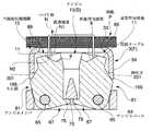
アンビル13は、図2、図3及び図5ないし図15に示すように、それぞれ前記折曲用当接面9及び成型用当接面11を有した対をなすアンビルメンバ61を具備してなるものであり、具体的には、前記ベース1に取付けられたアンビルベース63に前記両アンビルメンバ61をアンビルピン65を介して相互に接離する方向に回動可能に支持させたものである。  As shown in FIGS. 2, 3, and 5 to 15, theanvil 13 includes a pair ofanvil members 61 each having the bendingcontact surface 9 and themolding contact surface 11. Specifically, bothanvil members 61 are supported by ananvil base 63 attached to thebase 1 so as to be pivotable in a direction of contacting and separating from each other via ananvil pin 65.

前記アンビルメンバ61は、厚板状のもので、基端67をアンビルベース63に軸着するとともに、前記押刃7に対向する先端69に折曲用当接面9及び成型用当接面11を連続して形成したものである。前記折曲用当接面9は、前記両アンビルメンバ61が離間した位置で前記つづり針Nの先端N2を内側に案内する方向に用紙Pに対して傾斜したものであり、前記成型用当接面11は、前記両アンビルメンバ61が接近した位置で用紙Pと平行となるものである。なお、アンビルメンバ61は金属製のものであり、アンビルベース63は合成樹脂により一体成形されたものである。  Theanvil member 61 has a thick plate shape, and abase end 67 is pivotally attached to theanvil base 63, and a bendingcontact surface 9 and amolding contact surface 11 are formed on adistal end 69 facing thepressing blade 7. Are formed continuously. The bendingcontact surface 9 is inclined with respect to the sheet P in a direction in which the tip N2 of the spelling needle N is guided inward at a position where the twoanvil members 61 are separated from each other, Thesurface 11 is parallel to the paper P at a position where the twoanvil members 61 approach each other. Theanvil member 61 is made of metal, and theanvil base 63 is integrally formed of synthetic resin.

各アンビルメンバ61は、アンビルベース63の下方に設けられた弾性部材たる板ばね71によって、互いに離間する方向に付勢されている。73は、前記両アンビルメンバ61の係止用突起75を所定の離間位置(S)で係止するための係止用壁である。すなわち、これらのアンビルメンバ61は、前記離間位置(S)と相互に接触又は近接する接近位置(C)との間で回動し得るように規制されている。  Eachanvil member 61 is urged in a direction away from each other by aleaf spring 71 as an elastic member provided below theanvil base 63.Reference numeral 73 denotes a locking wall for locking the lockingprojections 75 of theanvil members 61 at a predetermined separation position (S). That is, theseanvil members 61 are regulated so as to be able to rotate between the separation position (S) and the approach position (C) that is in contact with or close to each other.

マガジン5は、図1、図2、図4及び図6ないし図8に示すように、前記用紙テーブル3に対向配置されつづり針Nを保持するためのもので、板金素材を折曲げることにより作られた上方に開放した箱形のものである。詳述すれば、このマガジン5は、底壁79と、この底壁79の両側縁から立ち上がる側壁81と、その側壁81の先端部を折曲げて形成された先端壁83とを具備してなる。前記底壁79の先端部には、押刃挿通用の窓85が形成されている。この底壁79の中間部には、前記両側壁81から切り起こすことにより形成された突片87が設けられている。この底壁79の中間部であって、前記突片87より先端寄りの位置には、後述するスライダ89の前動を規制するための突起91が突設されている。前記両側壁81の基端部には、軸孔部93が形成されており、それら両側壁81の内面には前記軸孔部93に軸心を一致させて円筒状のマガジンカバー取付軸95が形成されている。また、前記両側壁81の外面には、スライダ89をスライド可能に案内するための外レール97が突設されているとともに、これら外レール97に対応する前記両側壁81の内面には、プッシャ99をスライド可能に案内するための内レール101が凹設されている。  As shown in FIGS. 1, 2, 4 and 6 to 8, themagazine 5 is for holding the spelling needle N disposed opposite to the paper table 3, and is made by bending a sheet metal material. It is a box-shaped thing opened upward. More specifically, themagazine 5 includes abottom wall 79, aside wall 81 rising from both side edges of thebottom wall 79, and afront end wall 83 formed by bending the front end of theside wall 81. . Awindow 85 for pressing blade insertion is formed at the tip of thebottom wall 79. A projectingpiece 87 formed by cutting and raising from the bothside walls 81 is provided at an intermediate portion of thebottom wall 79. Aprotrusion 91 for restricting the forward movement of theslider 89 described later is provided in the middle of thebottom wall 79 at a position closer to the tip than the protrudingpiece 87.Shaft hole portions 93 are formed at the base end portions of the bothside walls 81, and cylindrical magazinecover mounting shafts 95 are formed on the inner surfaces of the bothside walls 81 so that the shaft centers coincide with theshaft hole portions 93. Is formed. Further,outer rails 97 are provided on the outer surfaces of theside walls 81 so as to guide theslider 89 in a slidable manner.Pushers 99 are provided on the inner surfaces of theside walls 81 corresponding to the outer rails 97. Aninner rail 101 for guiding the slidable guide is recessed.

そして、前記軸孔部93に前記ベース1の共通枢着部23に設けた軸状突起103を係わり合わせることによりベース1に対して上下方向に回動し得るように取付けられている。なお、このマガジン5をベース1に取付けた状態においては、前記突片87が、ベース1の内側壁17内面に形成された案内凹部105に上下動可能に挿入されており、その突片87が前記案内凹部105の上端に当接する上限位置(U)でマガジン5のベース1に対する上動が係止されるようになっている。このマガジン5は、ベース1に保持された弾性部材たるマガジンばね109により、前記上限位置(U)方向に付勢されている。  Theshaft hole 93 is attached to thebase 1 so that it can be rotated in the vertical direction by engaging the shaft-like protrusion 103 provided on thecommon pivot portion 23 of thebase 1. When themagazine 5 is attached to thebase 1, the protrudingpiece 87 is inserted into theguide recess 105 formed on the inner surface of theinner wall 17 of thebase 1 so as to be movable up and down. The upper movement of themagazine 5 with respect to thebase 1 is locked at the upper limit position (U) that contacts the upper end of theguide recess 105. Themagazine 5 is urged in the direction of the upper limit position (U) by amagazine spring 109 which is an elastic member held by thebase 1.

スライダ89は、図2、図4及び図6ないし図8に示すように、後述するテーブルロック機構43を構成するためのもので、合成樹脂により一部品で成形されている。詳述すれば、このスライダ89は、底壁111と、この底壁111の両側縁から立ち上がる側壁113とを具備してなる上方に開口するチャネル状のものである。前記両側壁113の外面には、テーブルロック機構43構成用のピン115が相互に軸心を一致させて突設してある。前記両側壁113の内面には、マガジン5の外レール97に前後方向にスライド移動可能に係わり合う凹溝117が形成されている。また、両側壁113の内面の上縁部分には、マガジン5の両側壁113の上端に係わり合う爪119が形成されている。この爪119の上面には、このスライダ89を下方からマガジン5に係合させる際に前記両側壁113を外方へ一時的に弾性変形させるための案内傾斜面121が形成されている。  As shown in FIGS. 2, 4 and 6 to 8, theslider 89 is for constituting atable lock mechanism 43 described later, and is formed of synthetic resin as a single component. More specifically, theslider 89 is in the form of a channel that opens upward and includes abottom wall 111 andside walls 113 that rise from both side edges of thebottom wall 111. On the outer surface of the bothside walls 113, pins 115 for constituting thetable lock mechanism 43 project from each other with their axes aligned. Aconcave groove 117 is formed on the inner surface of the bothside walls 113 to engage with theouter rail 97 of themagazine 5 so as to be slidable in the front-rear direction. Further, aclaw 119 that engages with the upper ends of theside walls 113 of themagazine 5 is formed at the upper edge portion of the inner surface of theside walls 113. On the upper surface of theclaw 119, a guideinclined surface 121 is formed for temporarily elastically deforming theside walls 113 outward when theslider 89 is engaged with themagazine 5 from below.

プッシャ99は、図2及び図4に示すように、マガジン5内に装填された一連のつづり針Nを先端N2方向に押圧するためのもので、合成樹脂により一部品で成形されている。詳述すれば、つづり針Nを押圧するための前壁123と、この前壁123の背面両側縁から後方に延出させた両側壁125と、これら両側壁125の後端部間に設けた後壁127とを具備してなる枠状のもので、前記両側壁125の外面には、前記マガジン5の内レール101に前後方向にスライド可能に係わり合う突条129が形成されている。この突条129の下面には、このプッシャ99をマガジン5内に上方から押入する際に、主に前記両側壁125を一時的に弾性変形させるための案内傾斜面131が形成されている。また、一方の側壁125の後側における上縁部には、上方に延出する延出壁133が形成されており、この延出壁133の内面にマガジンカバー135に保持されたプッシャばね137の先端を掛け止めするためのばね掛けピン139が突設されている。  As shown in FIGS. 2 and 4, thepusher 99 is used to press a series of spelling needles N loaded in themagazine 5 in the direction of the tip N2, and is formed from a synthetic resin as a single component. More specifically, the front wall 123 for pressing the spelling needle N, theside walls 125 extending rearward from both side edges of the front wall 123, and the rear ends of theside walls 125 are provided. Aridge 129 is formed on the outer surface of the bothside walls 125 so as to be slidable in the front-rear direction on theinner rail 101 of themagazine 5. On the lower surface of theprotrusion 129, a guideinclined surface 131 is mainly formed for temporarily elastically deforming theside walls 125 when thepusher 99 is pushed into themagazine 5 from above. Further, an extendingwall 133 extending upward is formed at the upper edge portion on the rear side of oneside wall 125, and thepusher spring 137 held by themagazine cover 135 is formed on the inner surface of the extendingwall 133. Aspring hook pin 139 is provided so as to hook the tip.

マガジンカバー135は、図1、図2、図4及び図6ないし図8に示すように、前記マガジン5の上面開口部141を塞ぎ得る位置に配置されつづり針Nを補充する際に開閉するもので、板金素材を折曲げることにより作られた下方に開放したチャネル状のものである。詳述すれば、このマガジンカバー135は、天壁143と、この天壁143の両側縁から垂下させた側壁145とを具備してなる。天壁143の先端には、マガジン5の上面開口部141を塞ぐ閉止位置(C)においてマガジン5の先端壁83に設けられた凹陥部149に係合する突片151が形成されている。また、天壁143の先端近傍部には、第一の窓153と、第二の窓155が中間壁157を介して隣接形成されている。天壁143の基端近傍部には、プッシャばね137の基端を掛止するためのフック159が形成されている。前記中間壁157は、前記両窓153、155を打ち抜き形成する際に形成される切起片を、天壁143の下面側に折り返してなる二重壁構造をなしているもので、側断面視において両端が滑らかな弧状をなすように成形されている。前記両側壁145の基端部には、半円弧状をなす軸受部161が形成されている。そして、その軸受部161を前記マガジン5のマガジンカバー取付軸95に係わり合わせることにより、このマガジンカバー135が前記マガジン5に開閉可能に取付けられている。  Themagazine cover 135 is arranged at a position where the upper surface opening 141 of themagazine 5 can be closed as shown in FIGS. 1, 2, 4 and 6 to 8, and is opened and closed when the spelling needle N is replenished. Then, it is a channel-like thing opened downward by making a sheet metal material. More specifically, themagazine cover 135 includes atop wall 143 andside walls 145 suspended from both side edges of thetop wall 143. At the top end of thetop wall 143, a projectingpiece 151 is formed that engages with arecess 149 provided in thefront end wall 83 of themagazine 5 at a closed position (C) that closes the upper surface opening 141 of themagazine 5. Further, afirst window 153 and asecond window 155 are formed adjacent to each other in the vicinity of the tip of thetop wall 143 through anintermediate wall 157. Ahook 159 for hooking the base end of thepusher spring 137 is formed in the vicinity of the base end of thetop wall 143. Theintermediate wall 157 has a double wall structure in which a cut and raised piece formed when thewindows 153 and 155 are punched and formed is folded back to the lower surface side of thetop wall 143. Are formed so that both ends form a smooth arc. A bearingportion 161 having a semicircular arc shape is formed at the base end portion of the bothside walls 145. Themagazine cover 135 is attached to themagazine 5 so as to be openable and closable by engaging the bearing 161 with the magazinecover attachment shaft 95 of themagazine 5.

プッシャばね137は、図2に示すように、比較的長尺な引っ張りコイルばねであり、フック159にかけられた基端から前記マガジンカバー135の天壁143下面に沿って前方に延出され、第一の窓153と第二の窓155を順次通過することにより、前記中間壁157に巻き掛けられている。そして、前記中間壁157をスライド可能に経由したプッシャばね137は、180度方向転換されて後方に延出され、その先端が前記プッシャ99のばね掛けピン139に掛け止めされる。このため、前記プッシャ99は、このプッシャばね137の弾性力により前方に弾性付勢されている。なお、この図2は、本実施形態を左右方向中央で切断した断面図であるが、プッシャばね137については切断することなく全体を記載している。  As shown in FIG. 2, thepusher spring 137 is a relatively long tension coil spring and extends forward along the bottom surface of thetop wall 143 of themagazine cover 135 from the base end hung on thehook 159. By sequentially passing through onewindow 153 andsecond window 155, it is wound around theintermediate wall 157. Then, thepusher spring 137 slidably passing through theintermediate wall 157 is turned 180 degrees and extended rearward, and its tip is hooked on thespring hook pin 139 of thepusher 99. Therefore, thepusher 99 is elastically biased forward by the elastic force of thepusher spring 137. FIG. 2 is a cross-sectional view of the present embodiment cut at the center in the left-right direction, but thepusher spring 137 is shown as a whole without being cut.

押刃7は、図1、図2、図4及び図6に示すように、前記マガジン5に保持されたつづり針Nを用紙テーブル3方向に押し出すためのもので、後述する押刃ベース19に取り付けられる押刃取付部163と、この押刃取付部163の先端側から下方に延出する押刃本体165とを具備してなる。押刃7は、板金素材を折曲げ加工して作られた金属製のもので、前記押刃本体165は、前記マガジン5の先端側に形成された窓85に挿通される。  As shown in FIGS. 1, 2, 4, and 6, thepressing blade 7 is used to push the spelling needle N held in themagazine 5 in the direction of the paper table 3. A pressingblade mounting portion 163 to be attached and a pressing blademain body 165 extending downward from the distal end side of the pressingblade mounting portion 163 are provided. Thepressing blade 7 is made of metal made by bending a sheet metal material, and thepressing blade body 165 is inserted through awindow 85 formed on the front end side of themagazine 5.

押刃ベース19は、図1、図2、図4及び図6ないし図8に示すように、前記押刃7を保持して、前記マガジン5に対して進退動作をし得るようにしたものであり、前記マガジン5に保持された一連のつづり針Nを一往復動作につき一本ずつ用紙P方向に供給するようになっている。具体的には、押刃ベース19は、板金素材を折曲げ加工して作られた金属製のもので、その基端部21は、ベース1の後端に設けられ前記マガジン5の基端部を枢支する共通枢着部23に回動可能に取り付けられている。この押刃ベース19の両側壁167の外面側には、ハンドル169の側壁171内面に形成されたカム溝173に係わり合うカムフォロワ175が設けられている。また、押刃ベース19の両側壁167の下縁部には、前記用紙テーブル3のロック用当接部41及びロックサポート45とともにテーブルロック機構43を構成するロック用案内部177を有する。このロック用案内部177は、前記スライダ89のピン115を案内すべく上方に延伸する傾斜部分179と、この傾斜部分179に連続して形成されロックが解除された際に前記スライダ89のピン115が嵌り込む凹陥部分181とを備えている。この押刃ベース19の天壁182には、弾性部材たる押刃ベースばね183を取り付けるためのスリット185を設けている。押刃ベースばね183は、この押刃ベース19を前記マガジン5から離間する方向へ付勢するためのもので、例えば、押刃ベース19側の端部がマガジン5側の端部よりも大径な円錐コイルばねである。  As shown in FIGS. 1, 2, 4, and 6 to 8, thepressing blade base 19 holds thepressing blade 7 and can move forward and backward with respect to themagazine 5. In addition, a series of spelling needles N held in themagazine 5 are supplied one by one in the paper P direction for each reciprocation. Specifically, thepressing blade base 19 is made of metal made by bending a sheet metal material, and itsbase end 21 is provided at the rear end of thebase 1 and is the base end of themagazine 5. Is pivotally attached to acommon pivot part 23 that pivots the frame. Acam follower 175 that engages with acam groove 173 formed on the inner surface of theside wall 171 of thehandle 169 is provided on the outer surface side of bothside walls 167 of thepressing blade base 19. In addition, the lower edge of bothside walls 167 of thepressing blade base 19 has a lockingguide portion 177 constituting thetable lock mechanism 43 together with thelock contact portion 41 and thelock support 45 of the paper table 3. The lockingguide portion 177 has aninclined portion 179 extending upward to guide thepin 115 of theslider 89, and thepin 115 of theslider 89 when the lock is released when the lock is released. And a recessedportion 181 into which is fitted. Thetop wall 182 of thepressing blade base 19 is provided with aslit 185 for attaching a pressingblade base spring 183 as an elastic member. The pressingblade base spring 183 is for urging thepressing blade base 19 in a direction away from themagazine 5. For example, the end portion on thepressing blade base 19 side has a larger diameter than the end portion on themagazine 5 side. Conical coil spring.

ハンドル169は、図1、図2及び図4に示すように、操作力を押刃ベース19に伝えるためのもので、合成樹脂により一部品で成形されている。詳述すれば、このハンドル169は、天壁187と、この天壁187の両側縁から垂下する側壁171と、前記天壁187の前縁から下方に延出する前壁189とを具備してなる。前記天壁187の上面には、予備のつづり針Nを保管するための保管スペース191が形成されており、この保管スペース191の上面開口部193には、キャップ195が開閉可能に蓋着されている。前記側壁171の後端部196は、前記ベース1に設けられたハンドル枢着部27に枢着されており、ベース1に対してこのハンドル169が上下方向に回動し得るようになっている。前記両側壁171の内面には、前記押刃ベース19のカムフォロワ175を案内して、当該ハンドル169の回動動作を前記押刃ベース19に伝達するためのカム溝173が形成されている。  As shown in FIGS. 1, 2 and 4, thehandle 169 is for transmitting an operating force to thepressing blade base 19, and is formed of a synthetic resin as a single part. More specifically, thehandle 169 includes atop wall 187,side walls 171 depending from both side edges of thetop wall 187, and afront wall 189 extending downward from the front edge of thetop wall 187. Become. Astorage space 191 for storing the spare spelling needle N is formed on the top surface of thetop wall 187, and acap 195 is attached to the upper surface opening 193 of thestorage space 191 so as to be openable and closable. Yes. Arear end portion 196 of theside wall 171 is pivotally attached to ahandle pivoting portion 27 provided on thebase 1, and thehandle 169 can rotate in the vertical direction with respect to thebase 1. .Cam grooves 173 for guiding thecam follower 175 of thepressing blade base 19 and transmitting the rotation of thehandle 169 to thepressing blade base 19 are formed on the inner surfaces of the bothside walls 171.

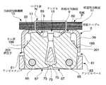
この実施形態においては、本発明の当接面切換機構15は、図5及び図9ないし図15に示すように、前記アンビルメンバ61に設けられたカム面199と、これらカム面199に摺接すべく前記用紙テーブル3に形成された押圧子201と、両アンビルメンバ61を付勢する弾性部材たる板ばね71とを主体にして構成されている。すなわち、当接面切換機構15は、前記アンビルメンバ61を接離する方向に回動付勢し得るように構成したものであり、本実施形態においては、前記用紙テーブル3の動きを利用して前記アンビルメンバ61を駆動するものとしている。当接面切換機構15を詳述すれば、前記アンビルメンバ61の外側面に設けられたカム面199と、これらカム面199に摺接すべく用紙テーブル3の側壁39に形成され当該用紙テーブル3の沈み込み動作時に前記カム面199を押圧して前記両アンビルメンバ61を接近する方向に付勢する押圧子201と、前記両アンビルメンバ61を離間する方向に付勢する弾性部材たる板ばね71とを主体に構成される。本実施形態においては、前記側壁39の下縁部分が前記押圧子201として機能するようになっている。  In this embodiment, the contactsurface switching mechanism 15 according to the present invention includes acam surface 199 provided on theanvil member 61 and a sliding contact with these cam surfaces 199, as shown in FIGS. Thepresser 201 formed on the paper table 3 and theleaf spring 71, which is an elastic member that urges bothanvil members 61, are mainly configured. In other words, the contactsurface switching mechanism 15 is configured to be able to turn and bias theanvil member 61 in the direction in which theanvil member 61 is contacted and separated. In the present embodiment, the movement of the paper table 3 is used. Theanvil member 61 is driven. More specifically, the contactsurface switching mechanism 15 is formed on acam surface 199 provided on the outer surface of theanvil member 61 and aside wall 39 of the paper table 3 so as to be in sliding contact with thecam surface 199. Apressing member 201 that presses thecam surface 199 to urge the twoanvil members 61 toward each other during a subsidence operation, and aleaf spring 71 that is an elastic member that urges the twoanvil members 61 to move away from each other. It is mainly composed. In the present embodiment, the lower edge portion of theside wall 39 functions as thepresser 201.

また、テーブルロック機構43は、図2、図3及び図6ないし図8に示すように、前記用紙テーブル3に設けられたロック用当接部41と、このロック用当接部41の下降を禁止するロック位置(L)と下降を許容する退避位置(S)との間で進退動作するロックサポート45と、このロックサポート45をロック位置(L)方向に付勢する弾性部材たるロックサポートばね53と、つづり針Nを用紙Pに打ち込む動作を利用して前記ロックサポート45を前記ロックサポートばね53の付勢力に抗して退避位置(S)方向に移動させる動作変換機構55とを具備してなる。  Further, as shown in FIGS. 2, 3 and 6 to 8, thetable lock mechanism 43 is provided with alock contact portion 41 provided on the paper table 3 and a lowering of thelock contact portion 41. Alock support 45 that moves forward and backward between a prohibited lock position (L) and a retracted position (S) that allows lowering, and a lock support spring that is an elastic member that urges thelock support 45 in the lock position (L) direction. 53 and anoperation converting mechanism 55 that moves thelock support 45 in the direction of the retracted position (S) against the urging force of thelock support spring 53 by using the operation of driving the spelling needle N into the paper P. It becomes.

この動作変換機構55は、前記押刃ベース19に設けられたロック用案内部177と、この押刃ベース19が用紙テーブル3に接近する際に前記案内部177に案内されてスライドするスライダ89とを具備してなるもので、このスライダ89のスライド動作により、前記ロックサポート45を退避位置(S)に移動させ得るように構成されている。具体的には、前記押刃ベース19のロック用案内部177とロックサポート45のサポートアーム59との間に前記スライダ89のピン115を位置させておき、押刃ベース19が下方に回動して前記案内部177によりピン115が後方に押圧されることにより、前記サポートアーム59が後方に移動するようになっている。  Themotion converting mechanism 55 includes a lockingguide portion 177 provided on thepressing blade base 19, and aslider 89 that is guided by the guidingportion 177 and slides when thepressing blade base 19 approaches the paper table 3. Thelock support 45 can be moved to the retracted position (S) by the sliding operation of theslider 89. Specifically, thepin 115 of theslider 89 is positioned between the lockingguide portion 177 of thepressing blade base 19 and thesupport arm 59 of thelock support 45, and thepressing blade base 19 rotates downward. Thus, when thepin 115 is pressed backward by theguide portion 177, thesupport arm 59 moves backward.

次にこのフラットクリンチ型ステープラの作動を説明する。  Next, the operation of this flat clinch type stapler will be described.

ハンドル169を操作しない状態では、図2に示すように、押刃ベース19、マガジン5、用紙テーブル3、アンビル13はそれぞれ初期位置に保持されている。詳述すれば、押刃ベース19は、前記押刃ベースばね183の付勢力により、マガジンカバー135から離間する方向に付勢された状態でマガジン5の上方に位置する。マガジン5は、前記マガジンばね109の付勢力により、ベース1から離間する方向に付勢された状態で、該マガジン5の側壁81に設けられた係合用の突起91がベース1の案内凹部105の段部分と係り合う上限位置(U)に保持される。用紙テーブル3は、前記用紙テーブルばね37の付勢力により、ベース1から離間する方向に付勢された状態で用紙固定位置(F)に位置する。アンビル13は、前記板ばね71の付勢力により、相互に離間する方向に付勢された状態で、各アンビルメンバ61に設けられた係止用突起75が、アンビルベース63に設けられた係止用壁73と係り合う離間位置(S)に保持される。  In a state where thehandle 169 is not operated, as shown in FIG. 2, thepressing blade base 19, themagazine 5, the paper table 3, and theanvil 13 are held at their initial positions. More specifically, thepressing blade base 19 is positioned above themagazine 5 while being urged in a direction away from themagazine cover 135 by the urging force of the pressingblade base spring 183. Themagazine 5 is urged in a direction away from thebase 1 by the urging force of themagazine spring 109, and an engagingprojection 91 provided on theside wall 81 of themagazine 5 is formed in theguide recess 105 of thebase 1. The upper limit position (U) that engages with the stepped portion is held. The paper table 3 is positioned at the paper fixing position (F) while being urged in a direction away from thebase 1 by the urging force of thepaper table spring 37. Theanvil 13 is urged in a direction away from each other by the urging force of theleaf spring 71, and a lockingprojection 75 provided on eachanvil member 61 is provided on theanvil base 63. The separated position (S) that engages with thework wall 73 is held.

この状態で、綴るべき用紙Pを用紙テーブル3上に添える。しかる後に、ハンドル169を前記用紙テーブル3側に近づけるように操作すると、まず、図6に示すように、押刃ベース19のカムフォロワ175がハンドル169の内面に設けられたカム溝173に沿って基端側へと案内されながら、前記ハンドル169と押刃ベース19との距離が接近していく。そして、前記マガジンばね109の付勢力に抗してマガジン5が用紙テーブル3側に接近するとともに、押刃7がマガジン5の先端側の壁の内面に沿って該マガジン5に設けられた窓85に向かって移動する。  In this state, the paper P to be bound is attached on the paper table 3. Thereafter, when thehandle 169 is operated so as to approach the paper table 3, first, as shown in FIG. 6, thecam follower 175 of thepressing blade base 19 is moved along thecam groove 173 provided on the inner surface of thehandle 169. While being guided toward the end side, the distance between thehandle 169 and thepressing blade base 19 approaches. Then, themagazine 5 approaches the paper table 3 side against the urging force of themagazine spring 109, and thepressing blade 7 is awindow 85 provided in themagazine 5 along the inner surface of the wall on the front end side of themagazine 5. Move towards.

この位置からハンドル169をさらに操作すると、前記押刃ベースばね183の付勢力に抗して押刃ベース19が用紙テーブル3側に近づくとともに、押刃7がマガジン5に保持されたつづり針Nのうち最先端の1本を押圧し、前記マガジン5から用紙Pに向かってつづり針Nが供給される。  When thehandle 169 is further operated from this position, thepressing blade base 19 approaches the paper table 3 against the biasing force of the pressingblade base spring 183 and thepressing blade 7 is held by themagazine 5 while holding thepressing blade 7. One of the most advanced ones is pressed, and a spelling needle N is supplied from themagazine 5 toward the paper P.

本実施形態においては、用紙Pの裏面側までつづり針Nの先端N2が貫通し終わるタイミングと、前記テーブルロック機構43によるロック状態が解除されるタイミングを略同時期としている。したがって、図7に示すように、マガジン5から用紙Pに向かってつづり針Nが供給される位置からハンドル169をさらに操作すると、図8に示すように、テーブルロック機構43によるロック状態が解除され、用紙テーブル3が沈み込み位置(D)まで移動する。用紙テーブル3が沈み込み位置(D)まで移動する過程において、つづり針Nの先端N2がアンビルメンバ61の先端69に向かって降下し、図9に示すように、アンビルメンバ61の折曲用当接面9に当接する。この状態で、さらに前記マガジンばね109の付勢力に抗してマガジン5が用紙テーブル3側に接近しており、図10乃至図13に示すように、前記つづり針Nの先端N2が、漸次接近する方向に移動するアンビルメンバ61の前記折曲用当接面9により内方に案内されて、そのつづり針Nの貫通端部N1が内方に折れ曲がっていく。そして、図14に示すように、その折れ曲がりが最終段階に達した時点で、アンビル13の成型用当接面11が前記つづり針Nに接することとなり、この成型用当接面11により前記つづり針Nの貫通端部N1が用紙Pの下面に略密着するようにフラットな状態に押し付け成形される。  In the present embodiment, the timing at which the tip N2 of the spelling needle N finishes penetrating to the back side of the paper P and the timing at which the locked state by thetable lock mechanism 43 is released are set substantially simultaneously. Therefore, when thehandle 169 is further operated from the position where the spelling needle N is supplied from themagazine 5 toward the paper P as shown in FIG. 7, the locked state by thetable lock mechanism 43 is released as shown in FIG. Then, the paper table 3 moves to the sinking position (D). In the process in which the paper table 3 moves to the sinking position (D), the tip N2 of the spelling needle N descends toward thetip 69 of theanvil member 61, and as shown in FIG. It contacts thecontact surface 9. In this state, themagazine 5 further approaches the paper table 3 side against the biasing force of themagazine spring 109, and the tip N2 of the spelling needle N gradually approaches as shown in FIGS. Theanvil member 61 is moved inwardly by the bendingcontact surface 9 so that the penetrating end N1 of the spelling needle N is bent inward. Then, as shown in FIG. 14, when the bending reaches the final stage, themolding contact surface 11 of theanvil 13 comes into contact with the spelling needle N, and the molding needle is contacted by themolding contact surface 11. The N penetrating end N1 is pressed and molded in a flat state so as to be in close contact with the lower surface of the paper P.

ついで、ハンドル169への操作を解除すると、まず、ハンドル169から押刃ベース19のカムフォロワ175に作用していた押圧力が解除され、押刃7によるつづり針Nに対する下方への押圧力が消勢する。それによって、押刃ベース19とマガジン5が解放され、これら押刃ベース19とマガジン5が、それぞれ押刃ベースばね183及びマガジンばね109の付勢力により上動する。その結果、用紙テーブル3が、主に用紙テーブルばね37の付勢力により上動し、アンビル13が板ばね71の付勢力により接近位置(C)から離間位置(S)へと復帰して、もとの待機状態である離間位置(S)に戻る。用紙テーブル3が用紙固定位置(F)付近まで上動すると、ロック用当接部41がロックサポート45の進退領域から外れた位置まで退避することになり、ロックサポート45がロックサポートばね53の付勢力によりロック位置(L)まで自己復帰し、初期状態となる。  Next, when the operation on thehandle 169 is canceled, the pressing force acting on thecam follower 175 of thepressing blade base 19 is first released from thehandle 169, and the downward pressing force on the spelling needle N by thepressing blade 7 is de-energized. To do. Accordingly, thepressing blade base 19 and themagazine 5 are released, and thepressing blade base 19 and themagazine 5 are moved upward by the urging force of the pressingblade base spring 183 and themagazine spring 109, respectively. As a result, the paper table 3 is moved upward mainly by the biasing force of thepaper table spring 37, and theanvil 13 is returned from the approach position (C) to the separated position (S) by the biasing force of theleaf spring 71. Return to the separation position (S) which is in a standby state. When the paper table 3 moves up to the vicinity of the paper fixing position (F), thelocking contact portion 41 is retracted to a position outside the advance / retreat area of thelock support 45, and thelock support 45 is attached to thelock support spring 53. It self-returns to the lock position (L) by the force and enters an initial state.

以上のような構成とすることにより、本実施形態に係るフラットクリンチ型ステープラは、綴るべき用紙Pを添えるための用紙テーブル3と、この用紙テーブル3に対向配置されつづり針Nを保持するマガジン5と、このマガジン5に保持されたつづり針Nを用紙テーブル3方向に押し出す押刃7と、この押刃7により押し出され前記用紙Pを貫通したつづり針Nの貫通端部N1を折曲用当接面9または成型用当接面11により折り曲げるためのアンビル13と、このアンビル13による折曲げ動作時に前記つづり針Nを前記折曲用当接面9に係わり合わせた後に前記成型用当接面11に係わり合わせる当接面切換機構15とを具備してなるので、つづり針Nを座屈等を招くことなくフラットな状態に折曲げて綴ることができる。すなわち、折曲用当接面9によってつづり針Nの先端N2を案内することができるため、つづり針Nの貫通端部N1の座屈を防ぐために当接面の傾斜をゆるく設定する必要がなくなるとともに、折曲用当接面9に係わり合った後のつづり針Nが成型用当接面11に係わり合わされるので、折曲げ最終段階において、前記つづり針Nの貫通端部N1における根本部分N3を十分に用紙P方向に押しつけることができる。そのため、その根本部分N3が若干用紙Pから離れる方向に膨らんだ状態で綴りが完了する不具合が解消される。  With the above configuration, the flat clinch type stapler according to the present embodiment has the paper table 3 for attaching the paper P to be bound, and themagazine 5 that holds the spelling needle N that is disposed facing the paper table 3. And a pushingblade 7 for pushing the spelling needle N held in themagazine 5 in the direction of the paper table 3, and a penetrating end N1 of the spelling needle N pushed through the paper P and pushed by the pushingblade 7 for bending. Ananvil 13 to be bent by thecontact surface 9 or themolding contact surface 11 and the molding contact surface after the spelling needle N is engaged with the bendingcontact surface 9 during the folding operation by theanvil 13. 11 is provided with the contactsurface switching mechanism 15 that engages with 11, the spelling needle N can be bent and spelled in a flat state without causing buckling or the like. That is, since the tip N2 of the spelling needle N can be guided by the bendingcontact surface 9, there is no need to set the inclination of the contact surface loosely in order to prevent buckling of the penetrating end N1 of the spelling needle N. At the same time, since the spelling needle N after being engaged with the bendingcontact surface 9 is engaged with themolding contact surface 11, at the final stage of bending, theroot portion N 3 at thepenetrating end N 1 of the spelling needle N is provided. Can be sufficiently pressed in the direction of the paper P. For this reason, the problem that the spelling is completed in a state where the root portion N3 slightly swells away from the paper P is solved.

特に、アンビル13が、それぞれ前記折曲用当接面9及び成型用当接面11を有した対をなすアンビルメンバ61を具備してなるので、折曲用当接面9のみを備えていた従来のアンビル13と比べて、成型用当接面11でつづり針Nをフラットな状態にすることができる。また、つづり針Nをフラットな状態に折り曲げて綴る成型用のために別途部品を取り付ける必要がなく、部品点数を削減することができる。さらに、アンビル13が、アンビルベース63に前記両アンビルメンバ61を回動可能に支持させたものであり、前記当接面切換機構15が、前記アンビルメンバ61を接離する方向に回動付勢し得るようにしているので、アンビルメンバ61をスライド移動させて当接面を切り換える場合よりも、切り換えのためのスペースが少なくて済む。また、各アンビルメンバ61は、前記押刃7に対向する先端69に折曲用当接面9及び成型用当接面11を連続して形成したものであるので、図9ないし図15に示すように、折り曲げ行程と成型行程をスムーズに連続させて綴り動作を行うことができる。  In particular, since theanvil 13 includes theanvil member 61 that forms a pair with the bendingcontact surface 9 and themolding contact surface 11, only the bendingcontact surface 9 is provided. Compared to theconventional anvil 13, the spelling needle N can be made flat at themolding contact surface 11. In addition, it is not necessary to separately attach parts for molding in which the spelling needle N is bent and spelled in a flat state, and the number of parts can be reduced. Further, theanvil 13 is configured such that both theanvil members 61 are rotatably supported by theanvil base 63, and the contactsurface switching mechanism 15 is urged to rotate in a direction in which theanvil member 61 is contacted and separated. Therefore, a space for switching can be reduced as compared with the case where theanvil member 61 is slid and the contact surface is switched. Eachanvil member 61 is formed by continuously forming the bendingcontact surface 9 and themolding contact surface 11 at thetip 69 facing thepressing blade 7, and is shown in FIGS. As described above, it is possible to perform the spelling operation by smoothly continuing the bending process and the molding process.

また、テーブルロック機構43を備えているので、不用意に用紙テーブル3が下方に押し下げられることがなくなる。そのため、用紙テーブル3の側壁39下端部に形成された押圧子201がアンビルメンバ61のカム面199を不用意に押すことがなくなる。すなわち、テーブルロック機構43のロックが解除されたときにのみ、用紙テーブル3が下方に移動し、綴り動作を行うことができるものとなっている。  Further, since thetable lock mechanism 43 is provided, the paper table 3 is not inadvertently pushed down. Therefore, thepresser 201 formed at the lower end of theside wall 39 of the paper table 3 does not inadvertently press thecam surface 199 of theanvil member 61. That is, only when the lock of thetable lock mechanism 43 is released, the paper table 3 moves downward and can perform a spelling operation.

なお、本発明は以上に述べた実施形態に限られない。  The present invention is not limited to the embodiment described above.

当接面切換機構は、スライド動作等の直線動作で接離可能に前記アンビルメンバを相対的に移動させるものであってもよい。  The contact surface switching mechanism may relatively move the anvil member so as to be able to contact and separate by a linear operation such as a slide operation.

用紙は、シート状のものであれば、紙製のものに限られず、プラスチック製のシート体や布製のシート体であってもよい。また、用紙の枚数も、図示したような比較的多い枚数の場合に限られず、一枚または少ない枚数であってもよい。  The paper is not limited to paper as long as it is in sheet form, and may be a plastic sheet or cloth sheet. Also, the number of sheets is not limited to a relatively large number as illustrated, and may be one or a small number.

その他、本発明の趣旨を損ねない範囲で種々に変更してよい。  In addition, various changes may be made without departing from the spirit of the present invention.

3…用紙テーブル
5…マガジン
7…押刃
9…折曲用当接面
11…成型用当接面
13…アンビル
15…当接面切換機構
61…アンビルメンバ
63…アンビルベース
199…カム面
201…押圧子
P…用紙
N…つづり針
N1…貫通端部
DESCRIPTION OFSYMBOLS 3 ... Paper table 5 ...Magazine 7 ... Pushblade 9 ... Bendingcontact surface 11 ...Molding contact surface 13 ...Anvil 15 ... Contactsurface switching mechanism 61 ...Anvil member 63 ...Anvil base 199 ...Cam surface 201 ... Presser P ... paper N ... spelling needle N1 ... through end

Claims (9)

Translated fromJapanese
綴るべき用紙を添えるための用紙テーブルと、この用紙テーブルに対向配置されつづり針を保持するマガジンと、このマガジンに保持されたつづり針を用紙テーブル方向に押し出す押刃と、この押刃により押し出され前記用紙を貫通したつづり針の貫通端部を折曲用当接面または成型用当接面により折り曲げるためのアンビルと、このアンビルによる折曲げ動作時に前記つづり針を前記折曲用当接面に係わり合わせた後に前記成型用当接面に係わり合わせる当接面切換機構とを具備してなることを特徴とするフラットクリンチ型ステープラ。A paper table for attaching paper to be bound, a magazine that is arranged opposite to the paper table and holds spelling needles, a push blade that pushes the spelling needles held in the magazine toward the paper table, and a push blade that is pushed out by the push blades An anvil for folding the penetrating end portion of the spelling needle penetrating the paper by a folding contact surface or a molding contact surface, and the spelling needle on the folding contact surface during the folding operation by the anvil. A flat clinch-type stapler comprising a contact surface switching mechanism that engages with the molding contact surface after being engaged.前記アンビルが、それぞれ前記折曲用当接面及び成型用当接面を有した対をなすアンビルメンバを具備してなるものであり、前記当接面切換機構が、前記アンビルメンバを相対的に移動させることによりつづり針に係り合う当接面を折曲用当接面から成型用当接面に切換えるように構成したものである請求項1記載のフラットクリンチ型ステープラ。The anvil includes a pair of anvil members each having the contact surface for bending and the contact surface for molding, and the contact surface switching mechanism relatively moves the anvil member relative to the anvil member. The flat clinch type stapler according to claim 1, wherein the contact surface engaged with the spelling needle is switched from the contact surface for bending to the contact surface for molding by moving.前記アンビルが、アンビルベースに前記両アンビルメンバを回動可能に支持させたものであり、前記当接面切換機構が、前記アンビルメンバを接離する方向に回動付勢し得るように構成したものである請求項2記載のフラットクリンチ型ステープラ。The anvil is configured such that both the anvil members are rotatably supported on an anvil base, and the abutment surface switching mechanism is configured to be able to urge the anvil member in a direction to contact and separate. The flat clinch-type stapler according to claim 2, which is a thing.前記当接面切換機構が、前記用紙テーブルの動きを利用して前記アンビルメンバを駆動するものである請求項2または3記載のフラットクリンチ型ステープラ。The flat clinch type stapler according to claim 2 or 3, wherein the contact surface switching mechanism drives the anvil member by using a movement of the paper table.前記当接面切換機構が、前記アンビルメンバの外側面に設けられたカム面と、これらカム面に摺接すべく用紙テーブルの側壁に形成され当該用紙テーブルの沈み込み動作時に前記カム面を押圧して前記両アンビルメンバを接近する方向に付勢する押圧子と、前記両アンビルメンバを離間する方向に付勢する弾性部材とを具備してなるものである請求項4記載のフラットクリンチ型ステープラ。The contact surface switching mechanism is formed on a cam surface provided on the outer surface of the anvil member and a side wall of the paper table so as to be in sliding contact with the cam surface, and presses the cam surface when the paper table is depressed. 5. A flat clinch-type stapler according to claim 4, further comprising: a pressing element that urges the two anvil members toward each other and an elastic member that urges the both anvil members toward each other. .前記アンビルメンバが、基端をアンビルベースに軸着するとともに、前記押刃に対向する先端に折曲用当接面及び成型用当接面を連続して形成したものである請求項2、3、4または5記載のフラットクリンチ型ステープラ。4. The anvil member has a proximal end pivotally attached to an anvil base and a bending contact surface and a molding contact surface formed continuously at a distal end facing the pressing blade. 4. A flat clinch-type stapler according to 4 or 5.前記折曲用当接面が、前記両アンビルメンバが離間した位置で前記つづり針の先端を内側に案内する方向に用紙に対して傾斜したものである請求項2、3、4、5または6記載のフラットクリンチ型ステープラ。7. The bending contact surface is inclined with respect to the sheet in a direction in which the front end of the spelling needle is guided inward at a position where the two anvil members are separated from each other. The flat clinch type stapler described.前記成型用当接面が、前記両アンビルメンバが接近した位置で用紙と平行となるものである請求項2、3、4、5、6または7記載のフラットクリンチ型ステープラ。The flat clinch-type stapler according to claim 2, 3, 4, 5, 6 or 7, wherein the molding contact surface is parallel to the sheet at a position where the two anvil members approach each other.綴るべき用紙を添えるための用紙テーブルと、この用紙テーブルに対向配置されつづり針を保持するマガジンと、このマガジンに保持されたつづり針を用紙テーブル方向に押し出す押刃と、この押刃により押し出され前記用紙を貫通したつづり針の貫通端部を折り曲げるためのアンビルとを具備するフラットクリンチ型ステープラであって、
前記アンビルが、折曲げ動作の最終段階でつづり針の貫通端部をフラットな状態に成形する成型用当接面を備えていることを特徴とするフラットクリンチ型ステープラ。
A paper table for attaching the paper to be bound, a magazine that is arranged opposite to the paper table and holds a spelling needle, a push blade that pushes the spelling needle held in the magazine toward the paper table, and a push blade that is pushed out by the push blade. A flat clinch-type stapler comprising an anvil for bending a penetrating end of a spelling needle penetrating the paper;
A flat clinch-type stapler, wherein the anvil includes a molding contact surface that molds the penetrating end of the spelling needle in a flat state at the final stage of the bending operation.
JP2009294570A2009-12-252009-12-25 Flat clinch type staplerActiveJP5521215B2 (en)

Priority Applications (3)

Application NumberPriority DateFiling DateTitle
JP2009294570AJP5521215B2 (en)2009-12-252009-12-25 Flat clinch type stapler
PCT/JP2010/073080WO2011078202A1 (en)2009-12-252010-12-22Flat clinch type stapler
CN2010800591139ACN102666026A (en)2009-12-252010-12-22Flat clinch type stapler

Applications Claiming Priority (1)

Application NumberPriority DateFiling DateTitle
JP2009294570AJP5521215B2 (en)2009-12-252009-12-25 Flat clinch type stapler

Publications (2)

Publication NumberPublication Date
JP2011131353Atrue JP2011131353A (en)2011-07-07
JP5521215B2 JP5521215B2 (en)2014-06-11

Family

ID=44195729

Family Applications (1)

Application NumberTitlePriority DateFiling Date
JP2009294570AActiveJP5521215B2 (en)2009-12-252009-12-25 Flat clinch type stapler

Country Status (3)

CountryLink
JP (1)JP5521215B2 (en)
CN (1)CN102666026A (en)
WO (1)WO2011078202A1 (en)

Cited By (2)

* Cited by examiner, † Cited by third party
Publication numberPriority datePublication dateAssigneeTitle
JP2013064458A (en)*2011-09-202013-04-11Max Co LtdStaple and stapler
CN112400518A (en)*2019-08-232021-02-26美克司株式会社Binding machine

Families Citing this family (3)

* Cited by examiner, † Cited by third party
Publication numberPriority datePublication dateAssigneeTitle
SE1300048A1 (en)*2013-01-182014-07-19Isaberg Rapid Ab Stapler
JP7651927B2 (en)*2021-04-152025-03-27マックス株式会社 Stapler
CN114800392B (en)*2021-11-012025-09-23得力集团有限公司 Bending nail plate of flat stapler and flat stapler

Citations (2)

* Cited by examiner, † Cited by third party
Publication numberPriority datePublication dateAssigneeTitle
JPS6235779U (en)*1985-08-191987-03-03
JPH08500777A (en)*1992-06-301996-01-30イサベルク・エービー Stapler with clinch mechanism

Family Cites Families (2)

* Cited by examiner, † Cited by third party
Publication numberPriority datePublication dateAssigneeTitle
US6966479B2 (en)*2001-03-052005-11-22Kokuyo Co., Ltd.Stapler
JP4144512B2 (en)*2003-11-102008-09-03コクヨ株式会社 Stapler

Patent Citations (2)

* Cited by examiner, † Cited by third party
Publication numberPriority datePublication dateAssigneeTitle
JPS6235779U (en)*1985-08-191987-03-03
JPH08500777A (en)*1992-06-301996-01-30イサベルク・エービー Stapler with clinch mechanism

Cited By (3)

* Cited by examiner, † Cited by third party
Publication numberPriority datePublication dateAssigneeTitle
JP2013064458A (en)*2011-09-202013-04-11Max Co LtdStaple and stapler
CN112400518A (en)*2019-08-232021-02-26美克司株式会社Binding machine
CN112400518B (en)*2019-08-232023-11-14美克司株式会社strapping machine

Also Published As

Publication numberPublication date
CN102666026A (en)2012-09-12
JP5521215B2 (en)2014-06-11
WO2011078202A1 (en)2011-06-30

Similar Documents

PublicationPublication DateTitle
JP5521215B2 (en) Flat clinch type stapler
JPH10227165A (en)Door opening and closing lock device
JP5861486B2 (en) Stapler
JP4322014B2 (en) Stapler
JP2009012095A (en)Stapler
JP2013166208A (en)Stapler
JP5040483B2 (en) Stapler
JP4826479B2 (en) Stapler
JP5045271B2 (en) Stapler
JP2017196729A (en)Stapler
JP5080142B2 (en) Stapler
JP6451254B2 (en) Binding device
EP1847476A1 (en)Sheet-like article storage container
JP2004230482A (en)Stapler
JP6645339B2 (en) Stapler
JP6645340B2 (en) Stapler
JP3718217B1 (en) Clip mounter with a punch above the insertion slot
JP2017193039A (en)Stapler
JP5317036B2 (en) Stopper for furniture
JP5716579B2 (en) Stapler
JP2003311647A (en)Stapler
JP2017061003A (en)Stapler
JP6357192B2 (en) stapler
JP5181429B2 (en) Paper support mechanism in paper press processing device
JP2017196731A (en)Stapler

Legal Events

DateCodeTitleDescription
A621Written request for application examination

Free format text:JAPANESE INTERMEDIATE CODE: A621

Effective date:20121112

A131Notification of reasons for refusal

Free format text:JAPANESE INTERMEDIATE CODE: A131

Effective date:20131224

A521Request for written amendment filed

Free format text:JAPANESE INTERMEDIATE CODE: A523

Effective date:20140131

TRDDDecision of grant or rejection written
A01Written decision to grant a patent or to grant a registration (utility model)

Free format text:JAPANESE INTERMEDIATE CODE: A01

Effective date:20140304

A61First payment of annual fees (during grant procedure)

Free format text:JAPANESE INTERMEDIATE CODE: A61

Effective date:20140317

R150Certificate of patent or registration of utility model

Ref document number:5521215

Country of ref document:JP

Free format text:JAPANESE INTERMEDIATE CODE: R150

S111Request for change of ownership or part of ownership

Free format text:JAPANESE INTERMEDIATE CODE: R313113

SZ03Written request for cancellation of trust registration

Free format text:JAPANESE INTERMEDIATE CODE: R313Z03

R350Written notification of registration of transfer

Free format text:JAPANESE INTERMEDIATE CODE: R350

S111Request for change of ownership or part of ownership

Free format text:JAPANESE INTERMEDIATE CODE: R313111

R350Written notification of registration of transfer

Free format text:JAPANESE INTERMEDIATE CODE: R350

R250Receipt of annual fees

Free format text:JAPANESE INTERMEDIATE CODE: R250

R250Receipt of annual fees

Free format text:JAPANESE INTERMEDIATE CODE: R250

R250Receipt of annual fees

Free format text:JAPANESE INTERMEDIATE CODE: R250

R250Receipt of annual fees

Free format text:JAPANESE INTERMEDIATE CODE: R250


[8]ページ先頭

©2009-2025 Movatter.jp