JP2011128921A - Touch panel and coordinate detection method for the same - Google Patents
Touch panel and coordinate detection method for the sameDownload PDFInfo
- Publication number
- JP2011128921A JP2011128921AJP2009287101AJP2009287101AJP2011128921AJP 2011128921 AJP2011128921 AJP 2011128921AJP 2009287101 AJP2009287101 AJP 2009287101AJP 2009287101 AJP2009287101 AJP 2009287101AJP 2011128921 AJP2011128921 AJP 2011128921A
- Authority
- JP
- Japan
- Prior art keywords
- conductive film
- coordinate
- region
- regions
- contact
- Prior art date
- Legal status (The legal status is an assumption and is not a legal conclusion. Google has not performed a legal analysis and makes no representation as to the accuracy of the status listed.)
- Granted
Links
Images


Classifications
- G—PHYSICS
- G06—COMPUTING OR CALCULATING; COUNTING
- G06F—ELECTRIC DIGITAL DATA PROCESSING
- G06F3/00—Input arrangements for transferring data to be processed into a form capable of being handled by the computer; Output arrangements for transferring data from processing unit to output unit, e.g. interface arrangements
- G06F3/01—Input arrangements or combined input and output arrangements for interaction between user and computer
- G06F3/03—Arrangements for converting the position or the displacement of a member into a coded form
- G06F3/041—Digitisers, e.g. for touch screens or touch pads, characterised by the transducing means
- G06F3/0416—Control or interface arrangements specially adapted for digitisers
- G06F3/0418—Control or interface arrangements specially adapted for digitisers for error correction or compensation, e.g. based on parallax, calibration or alignment
- G06F3/04186—Touch location disambiguation
- G—PHYSICS
- G06—COMPUTING OR CALCULATING; COUNTING
- G06F—ELECTRIC DIGITAL DATA PROCESSING
- G06F3/00—Input arrangements for transferring data to be processed into a form capable of being handled by the computer; Output arrangements for transferring data from processing unit to output unit, e.g. interface arrangements
- G06F3/01—Input arrangements or combined input and output arrangements for interaction between user and computer
- G06F3/03—Arrangements for converting the position or the displacement of a member into a coded form
- G06F3/041—Digitisers, e.g. for touch screens or touch pads, characterised by the transducing means
- G06F3/045—Digitisers, e.g. for touch screens or touch pads, characterised by the transducing means using resistive elements, e.g. a single continuous surface or two parallel surfaces put in contact
- G—PHYSICS
- G06—COMPUTING OR CALCULATING; COUNTING
- G06F—ELECTRIC DIGITAL DATA PROCESSING
- G06F2203/00—Indexing scheme relating to G06F3/00 - G06F3/048
- G06F2203/041—Indexing scheme relating to G06F3/041 - G06F3/045
- G06F2203/04104—Multi-touch detection in digitiser, i.e. details about the simultaneous detection of a plurality of touching locations, e.g. multiple fingers or pen and finger
Landscapes
- Engineering & Computer Science (AREA)
- General Engineering & Computer Science (AREA)
- Theoretical Computer Science (AREA)
- Human Computer Interaction (AREA)
- Physics & Mathematics (AREA)
- General Physics & Mathematics (AREA)
- Position Input By Displaying (AREA)
Abstract
Description
Translated fromJapanese本発明は、タッチパネル及びタッチパネルの座標検出方法に関する。 The present invention relates to a touch panel and a coordinate detection method for the touch panel.
抵抗膜方式のタッチパネルは、各々が透明な導電膜を備えた上部層と下部層とが対向して形成される。この方式のタッチパネルは、指やペン等でタッチパネルが押圧され、上部層の導電膜と下部層の導電膜とが接触し導通することにより、接触した点の座標を検出するものである。 The resistive film type touch panel is formed so that an upper layer and a lower layer each having a transparent conductive film face each other. In this type of touch panel, the touch panel is pressed with a finger, a pen, or the like, and the upper layer conductive film and the lower layer conductive film come into contact with each other, thereby detecting the coordinates of the contact point.
特許文献1には、導電膜を透明導電ポリマー材で形成した抵抗膜方式タッチパネルが開示されている。特許文献2には、導電膜を導電ポリマーや金属酸化膜で形成した抵抗膜方式タッチパネルが開示されている。
導電膜を複数の領域に分割し、領域ごとにタッチを検出する多点入力モードのタッチパネルでは、領域ごとに座標検出に用いる電圧のディスチャージを行うため、高速な検出動作が困難な場合がある。 In a multi-point input mode touch panel in which a conductive film is divided into a plurality of regions and a touch is detected in each region, a voltage used for coordinate detection is discharged in each region, so that a high-speed detection operation may be difficult.
又は、例えばタッチパネルをタッチした指等をスライドさせてタッチパネル上で描画を行うことがある。このような描画モードにおいては、タッチパネルの処理速度が遅い場合、描画を円滑に行えないことがある。 Alternatively, for example, a finger touching the touch panel may be slid to perform drawing on the touch panel. In such a drawing mode, if the processing speed of the touch panel is slow, drawing may not be performed smoothly.
又は、導電膜の分割された領域に、引き出し配線を含む領域がある場合、領域ごとにプルダウン抵抗値やフィルタの遮蔽周波数の変更をすることがある。プルダウン抵抗値やフィルタの遮蔽周波数変更の回数が多くなると、それだけタッチパネルの動作が遅くなる可能性がある。 Alternatively, when there is a region including a lead wiring in the divided region of the conductive film, the pull-down resistance value or the filter shielding frequency may be changed for each region. As the number of pull-down resistance values and the frequency of changing the filter shielding frequency increases, the operation of the touch panel may be delayed accordingly.
又は、引き出し配線と引き出し配線以外の領域とが、またがってタッチされた場合、ユーザが意図しない入力があったと判断され、タッチパネルが誤作動を起こす可能性がある。 Alternatively, when the lead-out wiring and the area other than the lead-out wiring are touched across, it is determined that there is an input that is not intended by the user, and the touch panel may malfunction.
本発明は上記課題に鑑み、高速化が可能なタッチパネル及びタッチパネルの座標検出方法を提供すること、又は座標検出の精度向上が可能なタッチパネル及びタッチパネルの座標検出方法を提供することを目的とする。 In view of the above problems, an object of the present invention is to provide a touch panel and touch panel coordinate detection method capable of speeding up, or to provide a touch panel and touch panel coordinate detection method capable of improving the accuracy of coordinate detection.
本発明は、互いに絶縁する複数の領域に分割された第1導電膜と、前記第1導電膜と対向し、かつ離間する第2導電膜と、前記第2導電膜が備える互いに対向する一組の電極と、前記第2導電膜が備え、互いに対向する、前記一組の電極とは別の一組の電極と、前記第1導電膜と前記第2導電膜とが接触したか、前記領域ごとに判断し、前記第1導電膜と前記第2導電膜とが接触した場合、前記一組の電極に電圧を印加することで、前記第1導電膜と前記第2導電膜とが接触した点のX座標又はY座標のいずれか一方を検出し、前記複数の領域の各々において前記X座標又はY座標のいずれか一方を検出した後に、前記一組の電極に印加した電圧を除去し、前記電圧を除去した後に、前記別の一組の電極に電圧を印加することで、前記複数の領域の各々において前記X座標又はY座標のいずれか他方を検出する制御部と、を具備するタッチパネルである。本発明によれば、ディスチャージの回数を減らすことにより、タッチパネルの高速化が可能となる。 The present invention relates to a first conductive film that is divided into a plurality of regions that are insulated from each other, a second conductive film that faces and separates from the first conductive film, and a pair of the second conductive film that face each other. The electrode and the second conductive film, and a pair of electrodes opposite to each other, the first conductive film and the second conductive film are in contact with each other, or the region When the first conductive film and the second conductive film are in contact with each other, the first conductive film and the second conductive film are in contact with each other by applying a voltage to the pair of electrodes. Detecting either the X coordinate or the Y coordinate of the point, and after detecting either the X coordinate or the Y coordinate in each of the plurality of regions, removing the voltage applied to the set of electrodes; After removing the voltage, by applying a voltage to the another set of electrodes, the plurality of A touch panel comprising a control unit for detecting the other one of the X-coordinate or Y-coordinate in each region. According to the present invention, it is possible to speed up the touch panel by reducing the number of discharges.
上記構成において、前記制御部は、前記複数の領域のいずれかの領域において前記第1導電膜と前記第2導電膜とが接触した場合、前記接触した領域において前記X座標又はY座標のいずれか一方を検出した後、前記複数の領域のうち前記接触した領域とは別の領域において前記第1導電膜と前記第2導電膜とが接触したか判断する構成とすることができる。この構成によれば、ディスチャージの回数を減らすことにより、タッチパネルの高速化が可能となる。 In the above configuration, when the first conductive film and the second conductive film are in contact with each other in any one of the plurality of regions, the control unit is configured to select either the X coordinate or the Y coordinate in the contacted region. After detecting one of the plurality of regions, it can be determined whether the first conductive film and the second conductive film are in contact with each other in a region different from the contacted region. According to this configuration, it is possible to increase the speed of the touch panel by reducing the number of discharges.
上記構成において、前記制御部は、前記複数の領域の各々において前記第1導電膜と前記第2導電膜とが接触したか判断した後に、前記複数の領域の各々において前記X座標又はY座標のいずれか一方を検出する構成とすることができる。この構成によれば、ディスチャージの回数を減らすことにより、タッチパネルの高速化が可能となる。また、タッチONチェックと、X座標及びY座標のいずれか一方の検出とを繰り返さなくてよい。従って、タッチパネルの更なる高速化が可能となる。 In the above configuration, the control unit determines whether the first conductive film and the second conductive film are in contact with each other in each of the plurality of regions, and then determines the X coordinate or Y coordinate in each of the plurality of regions. It can be set as the structure which detects any one. According to this configuration, it is possible to increase the speed of the touch panel by reducing the number of discharges. Further, it is not necessary to repeat the touch-on check and the detection of either the X coordinate or the Y coordinate. Therefore, the touch panel can be further increased in speed.
上記構成において、前記制御部は、前記第1導電膜と前記第2導電膜とが接触した場合、前記第1導電膜と前記第2導電膜とが接触した領域を記憶し、前記記憶された領域において前記X座標及びY座標を検出する構成とすることができる。この構成によれば、タッチパネルの更なる高速化が可能となる。 In the above configuration, when the first conductive film and the second conductive film are in contact with each other, the control unit stores a region in which the first conductive film and the second conductive film are in contact with each other and stores the stored area. The X coordinate and the Y coordinate can be detected in the region. According to this configuration, the touch panel can be further increased in speed.
本発明は、互いに絶縁する複数の領域に分割された第1導電膜と、前記第1導電膜と対向し、かつ離間する第2導電膜と、前記第1導電膜と前記第2導電膜とが接触した点の座標を出力した場合、前記座標を出力した動作の次の動作においては前記複数の領域のうち前記動作で座標を出力した領域、及び前記動作で座標を出力した領域の周辺の領域において、前記第1導電膜と前記第2導電膜とが接触した点の座標を検出し、前記動作で座標を出力した場合、前記複数の領域のうち、前記次の動作で座標を検出した領域、及び前記周辺の領域以外の領域においては、前記座標を検出しない制御部と、を具備するタッチパネルである。本発明によれば、分割された領域の全てに対して順次座標の検出を行う場合よりも、タッチパネルの高速化が可能となる。 The present invention includes a first conductive film that is divided into a plurality of regions that are insulated from each other, a second conductive film that faces and separates from the first conductive film, the first conductive film, and the second conductive film. When the coordinates of the contact point are output, in the next operation after the operation that outputs the coordinates, the region that outputs the coordinates in the operation and the periphery of the region that outputs the coordinates in the operation among the plurality of regions. In a region, when the coordinates of the point where the first conductive film and the second conductive film are in contact are detected and the coordinates are output in the operation, the coordinates are detected in the next operation among the plurality of regions. In a region other than the region and the surrounding region, the touch panel includes a control unit that does not detect the coordinates. According to the present invention, it is possible to increase the speed of the touch panel as compared with the case where coordinates are sequentially detected for all of the divided areas.
上記構成において、前記制御部は、前記次の動作においては、前記動作に基づき定められた方向に沿った領域ごとに、前記第1導電膜と前記第2導電膜とが接触した点の座標を検出する構成とすることができる。この構成によれば、タッチパネルの高速化が可能となる。 In the configuration described above, in the next operation, the control unit obtains coordinates of a point where the first conductive film and the second conductive film are in contact with each other along a direction determined based on the operation. It can be set as the structure detected. According to this configuration, it is possible to increase the speed of the touch panel.
本発明は、互いに絶縁する複数の領域に分割された第1導電膜と、前記第1導電膜と対向し、かつ離間する第2導電膜と、前記複数の領域のうち第1領域の主領域からなる第1グループと、前記第1領域の引き出し配線及び前記複数の領域のうち第2領域からなる第2グループと、の各々ごとに前記第1導電膜と前記第2導電膜とが接触した点の座標を検出する制御部と、を具備するタッチパネルである。本発明によれば、領域ごとに電位差を補正しなくてよく、またフィルタの遮蔽周波数を変更しなくてよいため、タッチパネルの高速化が可能となる。 The present invention provides a first conductive film that is divided into a plurality of regions that are insulated from each other, a second conductive film that faces and separates from the first conductive film, and a main region of the first region among the plurality of regions. The first conductive film and the second conductive film are in contact with each other of the first group consisting of the first wiring and the second group consisting of the second region out of the plurality of regions. And a control unit that detects the coordinates of the points. According to the present invention, it is not necessary to correct the potential difference for each region, and it is not necessary to change the shielding frequency of the filter, so that the touch panel can be speeded up.
上記構成において、前記第1グループ及び前記第2グループは、前記複数の領域を行又は列のいずれか一方ごとにまとめてなるグループであり、前記引き出し配線は前記行又は列のいずれか他方の方向に引き出されている構成とすることができる。この構成によれば、タッチパネルの高速化が可能となる。 In the above configuration, the first group and the second group are groups in which the plurality of regions are grouped in either row or column, and the lead-out wiring is in the other direction of the row or column. It can be set as the structure pulled out. According to this configuration, it is possible to increase the speed of the touch panel.
本発明は、互いに絶縁する複数の領域に分割された第1導電膜と、前記第1導電膜と対向し、かつ離間する第2導電膜と、各々が前記複数の領域のうち一部の領域からなる複数のグループの各々ごとに、前記第1導電膜と前記第2導電膜とが接触したか判断し、前記複数のグループのうち前記第1導電膜と前記第2導電膜とが接触したグループにおいて、前記第1導電膜と前記第2導電膜とが接触した点の座標を検出する動作を行い、かつ前記複数のグループのうち、前記第1導電膜と前記第2導電膜とが接触していないグループにおいては、前記座標を検出する動作を行わない制御部と、を具備するタッチパネルである。本発明によれば、各領域について順次制御を行う場合よりも、タッチONチェックや座標検出の制御の回数が少なくなる。従って、タッチパネルの高速化が可能となる。 The present invention provides a first conductive film that is divided into a plurality of regions that are insulated from each other, a second conductive film that is opposed to and spaced from the first conductive film, and each of the plurality of regions. For each of the plurality of groups, it is determined whether the first conductive film and the second conductive film are in contact with each other, and the first conductive film and the second conductive film are in contact with each other among the plurality of groups. In the group, an operation of detecting coordinates of a point where the first conductive film and the second conductive film are in contact with each other, and the first conductive film and the second conductive film are in contact with each other in the plurality of groups. In the group which is not, it is a touch panel provided with the control part which does not perform the operation | movement which detects the said coordinate. According to the present invention, the number of touch-on check and coordinate detection controls is smaller than when sequential control is performed for each region. Accordingly, it is possible to increase the speed of the touch panel.
上記構成において、前記複数のグループは、前記複数の領域のうち第1領域の主領域からなる第1グループと、前記第1領域の引き出し配線及び前記複数の領域のうち第2領域からなる第2グループと、を含む構成とすることができる。この構成によれば、領域ごとに電位差を補正しなくてよく、またフィルタの遮蔽周波数を変更しなくてよいため、タッチパネルのさらなる高速化が可能となる。 In the above configuration, the plurality of groups include a first group including a main region of the first region among the plurality of regions, and a second group including a second region among the lead-out wiring of the first region and the plurality of regions. And a group. According to this configuration, the touch panel need not be corrected for each region, and the shielding frequency of the filter need not be changed, so that the touch panel can be further increased in speed.
上記構成において、前記第1グループ及び前記第2グループは、前記複数の領域を行又は列のいずれか一方ごとにまとめてなるグループであり、前記引き出し配線は前記行又は列のいずれか他方の方向に引き出されている構成とすることができる。この構成によれば、タッチパネルのさらなる高速化が可能となる。 In the above configuration, the first group and the second group are groups in which the plurality of regions are grouped in either row or column, and the lead-out wiring is in the other direction of the row or column. It can be set as the structure pulled out. According to this configuration, it is possible to further increase the speed of the touch panel.
上記構成において、前記第1グループ及び前記第2グループの各々に接続され、互いに遮蔽周波数が異なる複数のフィルタを備える構成とすることができる。この構成によれば、領域ごとにフィルタの遮蔽周波数を変更しなくてよいため、タッチパネルのさらなる高速化が可能となる。 The said structure WHEREIN: It can be set as the structure provided with the some filter which is connected to each of the said 1st group and the said 2nd group and from which a shielding frequency differs mutually. According to this configuration, since it is not necessary to change the shielding frequency of the filter for each region, the touch panel can be further speeded up.
上記構成において、前記第1導電膜と前記第2導電膜とが接触したことに応じて、前記複数のグループの各々を構成する前記一部の領域の各々から送信される信号を、1つの信号として結合する結合手段を備え、前記制御部は前記結合手段により結合された前記1つの信号を受信したことに応じて、前記一部の領域からなるグループにおいて前記第1導電膜と前記第2導電膜とが接触したと判断する構成とすることができる。この構成によれば、簡単な構成により、自動的に第1導電膜2と第2導電膜4とが接触したグループを判断でき、座標を検出する動作を行うことができる。 In the above structure, a signal transmitted from each of the partial regions constituting each of the plurality of groups in response to the contact between the first conductive film and the second conductive film is a single signal. Coupling means for coupling the first conductive film and the second conductive film in the group consisting of the partial areas in response to receiving the one signal coupled by the coupling means. It can be set as the structure judged that the film | membrane contacted. According to this configuration, it is possible to automatically determine a group in which the first
本発明は、互いに絶縁する複数の領域に分割された第1導電膜と、前記第1導電膜と対向し、かつ離間する第2導電膜と、前記複数の領域のうち、第1領域と、第2領域と、前記第1領域及び前記第2領域との間に位置する第3領域の引き出し配線と、において前記第1導電膜と前記第2導電膜とが接触した場合であって、前記第1領域において前記第1導電膜と前記第2導電膜とが接触した点の座標である第1の座標と、前記第2領域において前記第1導電膜と前記第2導電膜とが接触した点の座標である第2の座標との差、及び前記第1の座標と、前記第3領域の引き出し配線において前記第1導電膜と前記第2導電膜とが接触した点の座標である第3の座標との差が、それぞれ所定の範囲内である場合、前記第1の座標及び前記第2の座標とに基づき、第4の座標を出力する制御部と、を具備するタッチパネルである。本発明によれば、引き出し配線を含む複数の領域において座標が検出された場合でも、検出された座標に基づき定めた座標を出力する。従って、タッチパネルの座標検出の精度が向上する。特に引き出し配線での入力は無視し、1点において入力があったと判断されるため、誤作動を抑制することが可能となる。 The present invention includes a first conductive film that is divided into a plurality of regions that are insulated from each other, a second conductive film that is opposed to and spaced apart from the first conductive film, and a first region of the plurality of regions, The first conductive film and the second conductive film are in contact with each other in the second region and the third region lead-out wiring located between the first region and the second region, and The first coordinates, which are the coordinates of the point where the first conductive film and the second conductive film are in contact with each other in the first region, and the first conductive film and the second conductive film are in contact with each other in the second region. The difference from the second coordinate which is the coordinate of the point, the first coordinate, and the coordinate of the point where the first conductive film and the second conductive film are in contact with each other in the extraction wiring of the third region When the difference from the coordinates of 3 is within a predetermined range, the first coordinates and the second coordinates Based on the target, a touch panel that includes a control unit for outputting a fourth coordinate, the. According to the present invention, even when coordinates are detected in a plurality of regions including the lead wiring, coordinates determined based on the detected coordinates are output. Therefore, the accuracy of coordinate detection of the touch panel is improved. In particular, the input at the lead-out wiring is ignored, and it is determined that there is an input at one point, so that malfunction can be suppressed.
上記構成において、前記制御部は、前記第1の座標と前記第2の座標との平均の座標を前記第4の座標として出力する構成とすることができる。この構成によれば、タッチパネルの座標検出の精度が向上する。 The said structure WHEREIN: The said control part can be set as the structure which outputs the average coordinate of a said 1st coordinate and a said 2nd coordinate as a said 4th coordinate. According to this configuration, the accuracy of coordinate detection of the touch panel is improved.
上記構成において、前記制御部は、前記第3領域の主領域において前記第1導電膜と前記第2導電膜とが接触した点の座標である第5の座標と、前記第4の座標とに基づき、第6の座標を検出し、前記第4の座標と前記第6の座標とに基づき、前記第5の座標を出力する構成とすることができる。この構成によれば、2箇所において座標が検出された場合でも、実際に入力があった点の座標を出力することができる。従って、タッチパネルの座標検出の精度が向上し、誤作動を抑制することが可能となる。 In the above configuration, the control unit may include a fifth coordinate that is a coordinate of a point where the first conductive film and the second conductive film are in contact with each other in the main region of the third region, and the fourth coordinate. Based on this, it is possible to detect the sixth coordinate and output the fifth coordinate based on the fourth coordinate and the sixth coordinate. According to this configuration, even when coordinates are detected at two locations, the coordinates of the points that are actually input can be output. Therefore, the accuracy of coordinate detection of the touch panel is improved, and malfunctions can be suppressed.
上記構成において、前記制御部は、前記第4の座標と前記第5の座標との平均の座標を第6の座標とする構成とすることができる。この構成によれば、タッチパネルの座標検出の精度が向上し、誤作動を抑制することが可能となる。 The said structure WHEREIN: The said control part can be set as the structure which uses the average coordinate of a said 4th coordinate and a said 5th coordinate as a 6th coordinate. According to this configuration, the accuracy of coordinate detection of the touch panel is improved, and malfunctions can be suppressed.
本発明は、互いに絶縁する複数の領域に分割された第1導電膜と、前記第1導電膜と対向し、かつ離間する第2導電膜とが接触したか、前記領域ごとに判断するステップと、前記第1導電膜と前記第2導電膜とが接触した場合、前記第2導電膜に設けられた、互いに対向する一組の電極に電圧を印加することで、前記第1導電膜と前記第2導電膜とが接触した点のX座標又はY座標のいずれか一方を検出するステップと、前記X座標又はY座標のいずれか一方を検出するステップを前記複数の領域の各々において行った後に、前記一組の電極に印加した電圧を除去するステップと、前記電圧を除去するステップの後に、互いに対向する、前記一組の電極とは別の一組の電極に電圧を印加することで、前記複数の領域の各々において前記X座標又はY座標のいずれか他方を検出するステップと、を有するタッチパネルの座標検出方法である。本発明によれば、ディスチャージの回数を減らすことにより、タッチパネルの高速化が可能となる。 Determining whether each of the first conductive film divided into a plurality of regions insulated from each other and a second conductive film facing and spaced apart from the first conductive film are in contact with each other; When the first conductive film and the second conductive film are in contact with each other, a voltage is applied to a pair of electrodes provided in the second conductive film that are opposed to each other. After performing the step of detecting either the X coordinate or the Y coordinate of the point in contact with the second conductive film and the step of detecting either the X coordinate or the Y coordinate in each of the plurality of regions. Removing a voltage applied to the set of electrodes and applying a voltage to a set of electrodes opposite to each other after the steps of removing the voltage and the set of electrodes, The X coordinate in each of the plurality of regions Is a coordinate detection method for a touch panel and a step of detecting the other of Y coordinate. According to the present invention, it is possible to speed up the touch panel by reducing the number of discharges.
本発明は、互いに絶縁する複数の領域に分割された第1導電膜と、前記第1導電膜と対向し、かつ離間する第2導電膜とが接触した点の座標を出力するステップと、前記出力するステップの後に、前記出力するステップにおいて座標を出力した領域、及び前記座標を出力した領域の周辺の領域で、前記第1導電膜と前記第2導電膜とが接触した点の座標を検出するステップと、を有し、前記座標を出力するステップにおいて座標を出力した場合前記複数の領域のうち、前記検出動作で座標を検出した領域、及び前記周辺の領域以外の領域においては、前記座標を検出しない、タッチパネルの座標検出方法である。本発明によれば、分割された領域の全てに対して順次座標の検出を行う場合よりも、タッチパネルの高速化が可能となる。 The present invention outputs a coordinate of a point where a first conductive film divided into a plurality of regions that are insulated from each other and a second conductive film facing and spaced apart from the first conductive film are in contact with each other; After the outputting step, the coordinates of the points where the first conductive film and the second conductive film are in contact with each other are detected in the region where the coordinates were output in the outputting step and the region around the region where the coordinates were output. And when the coordinates are output in the step of outputting the coordinates, in the areas other than the area where the coordinates are detected by the detection operation and the surrounding areas, the coordinates are output. This is a touch panel coordinate detection method that does not detect. According to the present invention, it is possible to increase the speed of the touch panel as compared with the case where coordinates are sequentially detected for all of the divided areas.
本発明は、互いに絶縁する複数の領域に分割された第1導電膜と、前記第1導電膜と対向し、かつ離間する第2導電膜とが接触した点の座標を検出する動作を、前記複数の領域のうち第1領域の主領域からなる第1グループにおいて行うステップと、前記座標を検出する動作を前記第1領域の引き出し配線及び前記複数の領域のうち第2領域からなる第2グループにおいて行うステップと、を有するタッチパネルの座標検出方法である。本発明によれば、領域ごとに電位差を補正しなくてよく、またフィルタの遮蔽周波数を変更しなくてよいため、タッチパネルの高速化が可能となる。 The present invention provides an operation of detecting coordinates of a point where a first conductive film divided into a plurality of regions insulated from each other and a second conductive film facing and spaced apart from the first conductive film are in contact with each other. The step of performing in the first group consisting of the main area of the first area among the plurality of areas, and the second group consisting of the lead wiring of the first area and the second area of the plurality of areas for detecting the coordinates A coordinate detection method for a touch panel. According to the present invention, it is not necessary to correct the potential difference for each region, and it is not necessary to change the shielding frequency of the filter, so that the touch panel can be speeded up.
本発明は、互いに絶縁する複数の領域に分割された第1導電膜と、前記第1導電膜と対向し、かつ離間する第2導電膜とが接触したか、各々が前記複数の領域のうち一部の領域からなる複数のグループの各々ごとに判断するステップと、前記複数のグループのうち前記第1導電膜と前記第2導電膜とが接触したグループにおいて、前記第1導電膜と前記第2導電膜とが接触した点の座標を検出する動作を行うステップと、を有し、前記複数のグループのうち、前記第1導電膜と前記第2導電膜とが接触していないグループにおいては、前記座標を検出する動作を行わないタッチパネルの座標検出方法である。本発明によれば、各領域について順次制御を行う場合よりも、タッチONチェックや座標検出の制御の回数が少なくなる。従って、タッチパネルの高速化が可能となる。 According to the present invention, a first conductive film divided into a plurality of regions that are insulated from each other and a second conductive film that faces the first conductive film and is separated from each other are in contact with each other. In the step of judging for each of a plurality of groups of partial regions, and in the group of the plurality of groups in which the first conductive film and the second conductive film are in contact, the first conductive film and the first conductive film Detecting a coordinate of a point where the two conductive films are in contact with each other, and in the group in which the first conductive film and the second conductive film are not in contact among the plurality of groups. The touch panel coordinate detection method does not perform the operation of detecting the coordinates. According to the present invention, the number of touch-on check and coordinate detection controls is smaller than when sequential control is performed for each region. Accordingly, it is possible to increase the speed of the touch panel.
本発明は、互いに絶縁する複数の領域に分割された第1導電膜と、前記第1導電膜と対向し、かつ離間する第2導電膜とが、前記複数の領域のうち、第1領域と、第2領域と、前記第1領域及び前記第2領域との間に位置する第3領域の引き出し配線と、において接触した場合に、前記第1領域において前記第1導電膜と前記第2導電膜とが接触した点の座標である第1の座標と、前記第2領域において前記第1導電膜と前記第2導電膜とが接触した点の座標である第2の座標との差、及び前記第1の座標と、前記第3領域の引き出し配線において前記第1導電膜と前記第2導電膜とが接触した点の座標である第3の座標との差が、それぞれ所定の範囲内であるか判断するステップと、前記第1の座標と前記第2の座標との差、及び前記第1の座標と前記第3の座標との差が前記所定の範囲内である場合、前記第1の座標及び前記第2の座標とに基づき、第4の座標を出力するステップと、を有するタッチパネルの座標検出方法である。本発明によれば、引き出し配線を含む複数の領域において座標が検出された場合でも、検出された座標に基づき定めた座標を出力する。従って、タッチパネルの座標検出の精度が向上する。特に引き出し配線での入力は無視し、1点において入力があったと判断されるため、誤作動を抑制することが可能となる。 According to the present invention, a first conductive film divided into a plurality of regions that are insulated from each other, and a second conductive film that faces the first conductive film and is spaced from the first conductive film, The first conductive film and the second conductive film in the first region when they are in contact with each other in the second region and the third region lead wiring located between the first region and the second region. A difference between a first coordinate which is a coordinate of a point where the film is in contact with a second coordinate which is a coordinate of a point where the first conductive film and the second conductive film are in contact with each other in the second region; The difference between the first coordinate and the third coordinate which is the coordinate of the point where the first conductive film and the second conductive film are in contact with each other in the lead wiring of the third region is within a predetermined range. Determining whether there is a difference between the first coordinate and the second coordinate, and the first coordinate A touch panel coordinate having a step of outputting a fourth coordinate based on the first coordinate and the second coordinate when a difference between the coordinate and the third coordinate is within the predetermined range; It is a detection method. According to the present invention, even when coordinates are detected in a plurality of regions including the lead wiring, coordinates determined based on the detected coordinates are output. Therefore, the accuracy of coordinate detection of the touch panel is improved. In particular, the input at the lead-out wiring is ignored, and it is determined that there is an input at one point, so that malfunction can be suppressed.
本発明によれば、高速化が可能なタッチパネル及びタッチパネルの座標検出方法を提供すること、又は座標検出の精度向上が可能なタッチパネル及びタッチパネルの座標検出方法を提供することができる。 According to the present invention, it is possible to provide a touch panel and a touch panel coordinate detection method capable of speeding up, or to provide a touch panel and touch panel coordinate detection method capable of improving the accuracy of coordinate detection.
図面を用いて、本発明の実施例について説明する。 Embodiments of the present invention will be described with reference to the drawings.
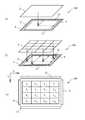
最初に、タッチパネルの構成について説明する。図1(a)及び図1(b)はタッチパネルの構成を例示する斜視図であり、図1(c)はタッチパネルの構成を例示する平面図である。 First, the configuration of the touch panel will be described. 1A and 1B are perspective views illustrating the configuration of the touch panel, and FIG. 1C is a plan view illustrating the configuration of the touch panel.
図1(a)は抵抗膜5線式のタッチパネルを例示する斜視図である。図1(a)に示すように、タッチパネル100は第1導電膜2、第2導電膜4、電極6,8,10及び12を備える。第1導電膜2と第2導電膜4とが互いに対向し、かつ離間して配置されている。第1導電膜2及び第2導電膜4はそれぞれ、例えばITO(Indium Tin Oxide:酸化インジウム・スズ)や有機導電ポリマー等の導電体からなる。第2導電膜4は、例えばAg等の金属からなる電極6,8,10及び12を備える。電極6,8,10及び12の各々は第2導電膜4の周辺部に、辺に沿って配置されている。すなわち電極6及び8、並びに電極10及び12は、互いに対向する一組の電極である。第1導電膜2、電極6,8,10及び12には、それぞれ電圧を印加することができる。 FIG. 1A is a perspective view illustrating a resistive film 5-wire touch panel. As shown in FIG. 1A, the
抵抗膜5線式のタッチパネルの原理について説明する。電極6,8,10及び12のいずれか、ここでは例えば電極6に電源電圧Vccを印加する。第1導電膜2にはプルダウン抵抗を接続する。第1導電膜2と第2導電膜4とが接触すると、Vccが印加された電極6とプルダウン抵抗とが接続され、プルダウン抵抗にかかる電位が高電位となり、高電位となったことにより第1導電膜2と第2導電膜4とが接触したことが検出される。ここで、電極6に対向する電極8に電圧Vssを印加すると、電極6と電極8との間に電位が発生する。電極から第1導電膜2と第2導電膜4とが接触した点(図の点線の部分)までの距離に応じて、導電膜の抵抗が変わるため、電極間に発生した電圧から第1導電膜2と第2導電膜4とが接触した点の座標を検出することができる。図1(a)の構成では、電極6及び電極8に電圧を印加してX座標を検出し、電極10及び電極12に電圧を印加してY座標を検出する。 The principle of the resistive film 5-wire touch panel will be described. The power supply voltage Vcc is applied to any one of the
図1(b)は、実施例1に係るタッチパネル100を例示する斜視図であり、図1(c)は図1(b)のタッチパネル100を第1導電膜2の上から見た平面図である。また、図1(c)には後述するX,Yの方向を図示する。図1(b)及び図1(c)に示すように、第1導電膜2は、格子状に4行4列の16の領域に分割されている。領域はF11〜F44とする。各領域は互いに絶縁されており、また領域ごとにプルダウン抵抗に接続される。このため、領域ごとに第1導電膜2と第2導電膜4との接触を検出することができる。すなわち実施例1に係るタッチパネル100は多点入力式タッチパネルである。 FIG. 1B is a perspective view illustrating the
次にタッチパネルの制御装置の構成について説明する。図2はタッチパネルの制御装置の構成を例示するブロック図である。 Next, the configuration of the touch panel control device will be described. FIG. 2 is a block diagram illustrating the configuration of the touch panel control device.
図2に示すように、制御装置14は、制御部16、電極制御部18、領域選択部20、フィルタ部22、A/D(Analog/Digital:アナログ/デジタル)変換部24、及びインターフェース部26を備える。 As shown in FIG. 2, the
電極制御部18は、図1(a)から図1(c)に示した電極6,8,10及び12の各々に接続されており、各電極に電圧を印加し、また印加した電圧を除去する。領域選択部20は、第1導電膜2と接続されており、第1導電膜2の分割された領域を選択する。領域選択部20は、第1導電膜2と第2導電膜4とが接触したことにより、第1導電膜2の選択された領域が送信する信号を受信する。フィルタ部22は例えば複数のローパスフィルタを備える。フィルタ部22は、第1導電膜2が送信する信号を、領域選択部20を介して受信し、ノイズを除去してA/D変換部24に送信する。A/D変換部24は、第1導電膜2が送信し、フィルタ部22によりノイズカットされた信号を、アナログ信号からデジタル信号へと変換する。 The
制御部16は、例えばマイコンであり、電極制御部18、領域選択部20、及びインターフェース部26を制御する。また、A/D変換部24が送信する信号を受信し、受信した信号に基づいて、領域F11〜F44のいずれの領域において第1導電膜2と第2導電膜4とが接触したか判断する。また制御部16は、第1導電膜2と第2導電膜4とが接触した点の座標を出力する。すなわち、制御部16は、受信した信号から座標変換を行う。インターフェース部26は、制御部16が出力した座標の情報を、タッチパネル100に接続された例えばコンピュータ等の外部機器に出力する。 The control unit 16 is a microcomputer, for example, and controls the
次に、領域選択部20の構成例について説明する。図3は領域選択部20の構成を例示する図である。 Next, a configuration example of the
図3に示すように、領域F11〜F14はマルチプレクサ30に、領域F21〜F24はマルチプレクサ32に、領域F31〜F34はマルチプレクサ34に、領域F41〜F44はマルチプレクサ36に、それぞれ接続されている。マルチプレクサ30〜36の各々は、接続された領域が送信する信号を受信し、また制御部16が送信するセレクト信号を受信する。また、マルチプレクサ30〜36の各々の出力側は、フィルタ部22に接続され、かつトランジスタ38及びプルダウン抵抗40を介して接地されている。すなわちトランジスタ38のコレクタに接続されている。トランジスタ38のエミッタはプルダウン抵抗40を介して接地され、トランジスタ38のベースには制御部16からの信号が入力する。マルチプレクサ30〜36が受信した各エリアからの信号のうち、セレクト信号により選択された信号は、フィルタ部22に送信され、かつトランジスタ38を介してプルダウン抵抗40に入力する。これにより、プルダウン抵抗40には高電位が加わり、第1導電膜2と第2導電膜4とが接触したことが検出される。 As shown in FIG. 3, the regions F11 to F14 are connected to the
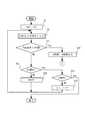
次に、実施例1に係るタッチパネルの制御について説明する。実施例の説明の前に、まず比較例について説明する。図4は、比較例に係るタッチパネルの制御を例示するフローチャートである。なお、図1(b)及び図1(c)に示した第1導電膜2の分割された領域のうち、m行n列目の領域をFmnと表すこととする。 Next, control of the touch panel according to the first embodiment will be described. Prior to the description of the examples, a comparative example will be described first. FIG. 4 is a flowchart illustrating the control of the touch panel according to the comparative example. Of the divided regions of the first
図4に示すように、制御部16は領域選択部20を、行番号をm=1、列番号をn=1とし領域F11が制御の対象となるように、制御する(ステップS1)。ステップS1の後、制御部16は、領域Fmnにおいて第1導電膜2と第2導電膜4とが接触したかチェックする動作を行う(ステップS2)。つまり、領域F11から開始して、領域Fmnごとにチェックの対象となる。なお、フローチャートでは、第1導電膜2と第2導電膜4とが接触したかチェックする動作を「タッチONチェック」と表記する。 As shown in FIG. 4, the control unit 16 controls the
ここで、タッチONチェックの制御についてフローチャートを用いて説明する。図5はタッチONチェック制御を例示するフローチャートである。 Here, the touch ON check control will be described with reference to a flowchart. FIG. 5 is a flowchart illustrating the touch ON check control.
図5に示すように、電極制御部18は、電極6に電圧Vccを印加する(ステップS14)。ステップS14の後、領域選択部20は領域Fmnをプルダウン抵抗Rと接続する(ステップS15)。ステップS15の後、制御部16はプルダウン抵抗Rの電位が高電位であるか判断する(ステップS16)。ステップS16においてYesの場合、制御部16は領域Fmnにおいて第1導電膜2と第2導電膜4とが接触したと判断する(ステップS17)。ステップS16においてNoの場合、制御部16は領域Fmnにおいて第1導電膜2と第2導電膜4とが接触していないと判断する(ステップS18)。ステップS17及びS18の後、制御は終了する。 As shown in FIG. 5, the
図4に戻り、ステップS2後の制御について説明する。ステップS2の後、制御部16は領域Fmnにおいて第1導電膜2と第2導電膜4とが接触したか判断する(ステップS3)。なお、第1導電膜2と第2導電膜4とが接触したことを「タッチON」と表記する。Noの場合、後述するステップS10に進む。 Returning to FIG. 4, the control after step S2 will be described. After step S2, the control unit 16 determines whether the first
Yesの場合、電極制御部18は電極6にVcc、電極8にVssを、それぞれ印加する(ステップS4)。これを「電極6=Vcc,電極8=Vss」と表記する。後述する電極10及び電極12についても同様とする。ステップS4の後、制御部16は第1導電膜2と第2導電膜4とが接触した点のX座標を検出する(ステップS5)。ステップS5の後、制御部16は電極6及び電極8のそれぞれに印加された電圧を除去(ディスチャージ)する(ステップS6)。ステップS6の後、電極制御部18は電極10にVcc、電極12にVssを印加する(ステップS7)。ステップS7の後、制御部16は領域F11のY座標を検出する(ステップS8)。ステップS8の後、制御部16は電極10及び電極12のディスチャージを行う(ステップS9)。 In the case of Yes, the
ステップS9の後、及びステップS3においてNoの場合、制御部16はmがMAXであるか判断する(ステップS10)。ここで「MAX」とは、分割された領域に付された行番号mのうち最大のものをいう。つまり図1(c)の例では、mがMAXであるとは、m=4のことをいう。Noの場合、制御部16は領域選択部20を、行番号mを1つ増やすように制御する(ステップS11)。ステップS11の後、制御はステップS2に戻り、制御部16は領域F21に対してステップS2以降の制御を行う。 After step S9 and in the case of No in step S3, the control unit 16 determines whether m is MAX (step S10). Here, “MAX” refers to the largest of the line numbers m assigned to the divided areas. That is, in the example of FIG. 1C, m being MAX means m = 4. In No, the control part 16 controls the area |
ステップS10においてYesの場合、つまりm=4である場合、制御部16はnがMAXであるか判断する(ステップS12)。ここで「MAX」とは、分割された領域に付された列番号nのうち最大のものをいう。つまりn=4がMAXとなる。Noの場合、制御部16は領域選択部20を、行番号をm=1とし、かつ列番号nを1つ増やすように制御する(ステップS13)。ステップS13の後、制御はステップS2に戻り、制御部16は領域F12に対してステップS2以降の制御を行う。ステップS13においてYesの場合、制御は終了する。 If Yes in step S10, that is, if m = 4, the control unit 16 determines whether n is MAX (step S12). Here, “MAX” refers to the largest of the column numbers n assigned to the divided areas. That is, n = 4 is MAX. In the case of No, the control unit 16 controls the
図4に示した比較例では、各領域においてタッチONチェック(ステップS2)、X座標の取り込み(ステップS5)及びY座標の取り込み(ステップS8)を順次行う。図4のステップS6及びS9に示すように、X座標の取り込みとY座標の取り込みとの間には、ディスチャージを行う。ディスチャージには一定の時間がかかる。従って、複数の領域において導電膜が接触した場合、その領域の数に応じて、ディチャージの回数も増加する。また、領域の数が多くなるほど、図4のステップS2以降の制御を繰り返すことになる。この結果、タッチパネルの動作が遅くなる可能性がある。このように、多点入力式のタッチパネルでは、タッチパネルの高速化に問題があった。 In the comparative example shown in FIG. 4, the touch-on check (step S2), the X coordinate capture (step S5), and the Y coordinate capture (step S8) are sequentially performed in each region. As shown in steps S6 and S9 in FIG. 4, discharge is performed between the capture of the X coordinate and the capture of the Y coordinate. Discharging takes a certain amount of time. Therefore, when the conductive film is in contact with a plurality of regions, the number of times of decharging increases according to the number of the regions. Further, the control after step S2 in FIG. 4 is repeated as the number of regions increases. As a result, the operation of the touch panel may be slow. Thus, the multipoint input type touch panel has a problem in speeding up the touch panel.
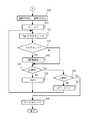
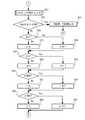
次に、実施例1に係るタッチパネルの制御について説明する。図6及び図7は実施例1に係るタッチパネルの制御を例示するフローチャートである。 Next, control of the touch panel according to the first embodiment will be described. 6 and 7 are flowcharts illustrating the control of the touch panel according to the first embodiment.
図6に示すように、まず制御部16は各領域のフラグをリセットする(ステップS20)。ステップS20の後、制御部16は図4のステップS1〜S3の制御を行う。つまり制御部16は、領域F11から開始して、領域Fmnごとに、第1導電膜2と第2導電膜4とが接触したか判断する。ステップS3においてNoの場合、後述するステップS24に進む。Yesの場合、制御部16はタッチONであると判断された領域Fmnにフラグをセットする(ステップS21)。 As shown in FIG. 6, first, the control unit 16 resets the flag of each region (step S20). After step S20, the control unit 16 performs the control of steps S1 to S3 in FIG. That is, the control unit 16 starts from the region F11 and determines whether the first
ステップS21の後、制御部16は電極制御部18を、電極6にVcc、電極8にVssを印加するように制御する(ステップS22)。ステップS22の後、制御部16は、領域Fmnにおいて、第1導電膜2と第2導電膜4とが接触した点のX座標を検出する(ステップS23)。ステップS23の後、ステップS24に進む。ステップS24〜S27は図4のステップS10〜S13と同じである。すなわち、X座標を検出した後、制御部16は、ステップS3においてタッチONであると判断された領域とは別の領域において、第1導電膜2と第2導電膜4とが接触したか判断する。 After step S21, the control unit 16 controls the
ステップS26においてYesの場合、制御部16は電極制御部18を、電極6及び電極8のそれぞれに印加した電圧をディスチャージするように制御する(ステップS28)。すなわち、制御部16は、領域Fmnの各々においてX座標を検出した後に、電極6及び電極8のそれぞれに印加した電圧を除去する。ステップS28の後、図7のステップS29に進む(図中の“A”参照)。 In the case of Yes in step S26, the control unit 16 controls the
図7に示すように、ステップS28の後、制御部16は電極制御部18を、電極10にVcc、電極12にVssをそれぞれ印加するように制御する(ステップS29)。ステップS29の後、制御部16は、行番号をm=1、列番号をn=1とする(ステップS30)。ステップS30の後、制御部16は領域Fmnのいずれかにフラグがセットされているかチェックする(ステップS31)。ステップS31の後、制御部16はフラグのセットがされているか判断する(ステップS32)。 As shown in FIG. 7, after step S28, the control unit 16 controls the
Yesの場合、制御部16は、フラグがセットされた領域において、第1導電膜2と第2導電膜4とが接触した点のY座標を検出する(ステップS33)。すなわち、制御部16は、第1導電膜2と第2導電膜4とが接触した領域を記憶し、記憶した領域においてY座標を検出する。ステップS33の後、又はステップS32においてNoの場合、ステップS34に進む。ステップS34〜S37は図4のステップS10〜S13と同じである。ステップS36においてYesの場合、制御部16は電極制御部18を、電極10及び電極12のそれぞれに印加した電圧をディスチャージするように制御する(ステップS38)。ステップS38の後、制御は終了する。 In the case of Yes, the control part 16 detects the Y coordinate of the point which the 1st
実施例1によれば、領域Fmnの各々においてX座標を検出した後ディスチャージを行い、その後に領域Fmnの各々においてY座標を検出した後ディスチャージを行うため、領域の数に関らずディスチャージは2回だけとなる(図6のステップS28及び図7のステップS38)。つまり、ディスチャージの回数を減らすことにより、タッチパネルの高速化が可能となる。また、第1導電膜2と第2導電膜4とが接触した領域を記憶し、記憶した領域においてY座標の検出を行う(図6のステップS21及び図7のステップS33)。第1導電膜2と第2導電膜4とが接触しているか判断し直さなくてよいため、タッチパネルの更なる高速化が可能となる。 According to the first embodiment, the discharge is performed after the X coordinate is detected in each of the regions Fmn, and then the discharge is performed after the Y coordinate is detected in each of the regions Fmn. Therefore, the discharge is 2 regardless of the number of regions. Only once (step S28 in FIG. 6 and step S38 in FIG. 7). That is, the speed of the touch panel can be increased by reducing the number of discharges. Further, the region where the first
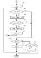
次に、実施例1の変形例について説明する。図8及び図9は、実施例1の変形例に係るタッチパネルの制御を例示するフローチャートである。 Next, a modification of the first embodiment will be described. 8 and 9 are flowcharts illustrating the touch panel control according to the modification of the first embodiment.
図8に示すように、ステップS20、S1〜3及びS21は、図6に示したものと同じ制御である。ステップS20においてNoの場合、又はステップS21の後、ステップS24に進む。ステップS24〜S27も、図6に示したものと同じである。言い換えれば、図8に示す制御は、図6に示した制御とは、電圧の印加(ステップS22)、X座標の検出(ステップS23)、及びディスチャージ(ステップS28)を行わない点で相違する。ステップS26においてYesの場合、図9のステップS29に進む(図中の“B”参照)。 As shown in FIG. 8, steps S20, S1-3, and S21 are the same control as that shown in FIG. If No in step S20 or after step S21, the process proceeds to step S24. Steps S24 to S27 are also the same as those shown in FIG. In other words, the control shown in FIG. 8 is different from the control shown in FIG. 6 in that voltage application (step S22), X coordinate detection (step S23), and discharge (step S28) are not performed. If Yes in step S26, the process proceeds to step S29 in FIG. 9 (see “B” in the figure).
図9に示すように、制御部16は電極制御部18を、電極6にVcc、電極8にVssをそれぞれ印加するように制御する(ステップS29)。ステップS29の後、制御部16は、行番号をm=1、列番号をn=1とする(ステップS30)。ステップS30の後は、図7に示したステップS31及びS32と同じ制御を行う。ステップS32においてYesの場合、制御部16は第1導電膜2と第2導電膜4とが接触した点のX座標を検出する(ステップS40)。 As shown in FIG. 9, the controller 16 controls the
ステップS40の後、又はステップS32においてNoの場合、ステップS24に進む。ステップS24〜S27は、図6に示したものと同じである。ステップS26においてYesの場合、制御部16は電極制御部18を、電極6及び電極8のそれぞれに印加した電圧をディスチャージするように制御する(ステップS41)。すなわち制御部16は、図8に示すように領域Fmnの各々において第1導電膜2と第2導電膜4とが接触したか判断した後に、図9に示すように領域Fmnの各々においてX座標を検出する。ステップS41の後、図7のステップS29に進む(図中の“A”参照)。図7に示すステップS38の後、制御は終了する。 After step S40 or if No in step S32, the process proceeds to step S24. Steps S24 to S27 are the same as those shown in FIG. If Yes in step S26, the control unit 16 controls the
実施例1の変形例によれば、領域Fmnの各々においてX座標を検出した後ディスチャージを行った後、領域Fmnの各々においてY座標を検出し、その後ディスチャージを行う。このため、領域の数に関らずディスチャージは2回だけとなる。従って、タッチパネルの高速化が可能となる。また実施例1の変形例によれば、複数の領域の各々においてタッチONチェックをした後、領域の各々においてX座標の検出をし、さらにその後にY座標の検出を行う。従って、図6のステップS3〜S23のように、タッチONチェックとX座標の検出とを繰り返さなくてよい。従って、タッチパネルの更なる高速化が可能となる。 According to the modification of the first embodiment, the discharge is performed after the X coordinate is detected in each of the regions Fmn, the Y coordinate is detected in each of the regions Fmn, and then the discharge is performed. For this reason, discharge is performed only twice regardless of the number of regions. Accordingly, it is possible to increase the speed of the touch panel. Further, according to the modification of the first embodiment, after a touch-on check is performed in each of the plurality of areas, the X coordinate is detected in each of the areas, and then the Y coordinate is detected. Therefore, it is not necessary to repeat the touch-on check and the detection of the X coordinate as in steps S3 to S23 in FIG. Therefore, the touch panel can be further increased in speed.
実施例1ではX座標をY座標より先に検出する制御を説明したが、Y座標をX座標より先に検出してもよい。つまり、X座標又はY座標のいずれか一方を検出した後に、電圧を除去し、その後にX座標又はY座標のいずれか他方を検出することで、ディスチャージの回数を低減でき、タッチパネルの高速化が可能となる。 In the first embodiment, the control for detecting the X coordinate before the Y coordinate has been described. However, the Y coordinate may be detected before the X coordinate. In other words, after detecting either the X coordinate or the Y coordinate, the voltage is removed, and then the other of the X coordinate or the Y coordinate is detected, so that the number of discharges can be reduced, and the touch panel speed can be increased. It becomes possible.
図1(b)及び図1(c)に例示するように、第1導電膜2を16の領域に分割した例について説明したが、より多くの領域又は少ない領域に分割してもよい。また、行数と列数とは異なっていてもよい。図3では、複数の領域を行ごとに1つのマルチプレクサ及びプルダウン抵抗に接続したが、接続の方法はこれに限られず、例えば行ごととしてもよい。 As illustrated in FIGS. 1B and 1C, the example in which the first
次に、実施例2について説明する。図10(a)は実施例2に係るタッチパネル200を例示する平面図であり、図10(b)は実施例2の変形例に係るタッチパネル210を例示する平面図である。なお、図10(b)には後述するベクトルの方向の例も図示する。まず図10(a)の例について説明する。 Next, Example 2 will be described. FIG. 10A is a plan view illustrating a
多点入力式のタッチパネルにおいても、1点入力モードが用いられることがある。タッチパネル200は、1点入力モードである。タッチパネルにおいては、例えば指等によりタッチパネルをタッチした状態で、指等をスライドさせてタッチパネル上で描画を行うことがある。このような描画モードにおいては、描画を円滑に行うため、タッチパネルの高速化が要求されている。この点について、図10(a)を参照して説明する。 Even in a multi-point input type touch panel, a one-point input mode may be used. The
図10(a)に示すように、タッチパネル200の第1導電膜2はF11〜F44の領域に分割されている。例えば領域F22がタッチされた場合、描画モードにおいては指等が領域F22から移動し、領域F22に隣接する領域もタッチされる。このとき、領域F11から順次座標検出を行うと、指等の移動に対してタッチパネルの処理速度が遅くなり、描画を円滑に行えないことがある。 As shown in FIG. 10A, the first
実施例2に係るタッチパネル200では、図中に網掛けで示す領域F22において第1導電膜2と第2導電膜4とが接触した場合、次の動作では領域F22、並びに領域F22に隣接する領域であるF11〜F13、F21、F23、及びF31〜F33(図中の斜線の領域)において、第1導電膜2と第2導電膜4とが接触したか、他の領域に優先して判断する。 In the
次に、フローチャートを参照し、実施例2に係るタッチパネル200の動作について、より詳細に説明する。図11から図13は、実施例2に係るタッチパネルの制御を例示するフローチャートである。 Next, the operation of the
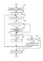
図11に示すステップS1〜S3、及びステップS24〜S27は同じ制御である。ステップS3においてNoの場合、制御はステップS24に進み、ステップS26においてYesの場合、制御は終了する。ステップS3においてYesの場合、つまり領域Fmnにおいて第1導電膜2と第2導電膜4とが接触した場合、制御部16は領域Fmnにおいて第1導電膜2と第2導電膜4とが接触した点のX座標、及びY座標を出力する(ステップS50)。X座標及びY座標の出力は、例えば図4に示したステップS4〜S9の制御により行われる。 Steps S1 to S3 and steps S24 to S27 shown in FIG. 11 are the same control. If No in step S3, the control proceeds to step S24. If Yes in step S26, the control ends. In the case of Yes in step S3, that is, when the first
ステップS50の後、図12のステップS51に進む(図中の“C”参照)。制御部16は領域Fmn、つまりステップS3においてタッチONと判断された領域において、第1導電膜2と第2導電膜4とが接触したかチェックする(ステップS51)。ステップS51の後、制御部16は第1導電膜2と第2導電膜4とが接触したか判断する(ステップS52)。ステップS52においてYesの場合、制御部16は、第1導電膜2と第2導電膜4とが接触した点のX座標、及びY座標を出力する(ステップS53)。すなわち制御部16は、ステップS50において第1導電膜2と第2導電膜とが接触した点の座標を出力した場合、座標を出力した動作(ステップS50)の次の動作においては複数の領域のうち、ステップS50において座標を出力した領域Fmnにおいて、タッチONチェック、及び座標の検出を行う。ステップS53の後、制御は図14のステップS76に進む(図12及び図14の“C1”参照)。C1に進んだ後の制御は、後述する実施例2の変形例において説明する。 After step S50, the process proceeds to step S51 in FIG. 12 (see “C” in the figure). The controller 16 checks whether the first
ステップS52においてNoの場合、制御部16はmが1より大きいか判断する(ステップS54)。Noの場合、制御部16はp=mとする(ステップS55)。なお、ステップS54においてNoとなるのは、図11のステップS3において1行目の領域がタッチONと判断された場合である。Yesの場合、制御部16はp=m−1とする(ステップS56)。 In the case of No in step S52, the control unit 16 determines whether m is greater than 1 (step S54). In the case of No, the control unit 16 sets p = m (step S55). Note that No in step S54 is a case where it is determined in step S3 in FIG. 11 that the area in the first row is touch-on. In the case of Yes, the control unit 16 sets p = m−1 (step S56).
ステップS55又はS56の後、制御部16はnが1より大きいか判断する(ステップS57)。Noの場合、制御部16はq=nとする(ステップS58)。なお、ステップS57においてNoとなるのは、図11のステップS3において1列目の領域がタッチONと判断された場合である。Yesの場合、制御部16はq=n−1とする(ステップS59)。 After step S55 or S56, the controller 16 determines whether n is greater than 1 (step S57). In the case of No, the control unit 16 sets q = n (step S58). Note that No in step S57 is a case where it is determined in step S3 in FIG. 11 that the region in the first column is touch-on. In the case of Yes, the control unit 16 sets q = n−1 (step S59).
ステップS58又はS59の後、制御部16はmがMAXより小さいか判断する(ステップS60)。ここでMAXとは行番号のうち最大のものである4である。Noの場合、制御部16はr=mとする(ステップS61)。なお、ステップS61においてNoとなるのは、図11のステップS3において4行目の領域がタッチONと判断された場合である。Yesの場合、制御部16はr=m+1とする(ステップS62)。 After step S58 or S59, the control unit 16 determines whether m is smaller than MAX (step S60). Here, MAX is 4 which is the largest of the row numbers. In the case of No, the control unit 16 sets r = m (step S61). Note that No in step S61 is a case where it is determined in step S3 in FIG. 11 that the region in the fourth row is touch-on. In the case of Yes, the control unit 16 sets r = m + 1 (step S62).
ステップS61又はS62の後、制御部16はnがMAXより小さいか判断する(ステップS63)。ここでMAXとは列番号のうち最大のものである4である。ステップS63においてNoの場合、制御部16はs=nとする(ステップS64)。なお、ステップS64においてNoとなるのは、図11のステップS3において4列目の領域がタッチONと判断された場合である。ステップS63においてYesの場合、制御部16はs=n+1とする(ステップS65)。ステップS65の後、制御は図13のステップS66に進む(図中の“D”参照)。 After step S61 or S62, the control unit 16 determines whether n is smaller than MAX (step S63). Here, MAX is 4 which is the largest of the column numbers. In the case of No in step S63, the control unit 16 sets s = n (step S64). Note that No in step S64 is the case where it is determined in step S3 in FIG. 11 that the region in the fourth column is touch-on. If Yes in step S63, the control unit 16 sets s = n + 1 (step S65). After step S65, control proceeds to step S66 in FIG. 13 (see “D” in the figure).
制御部16はpp=pとする(ステップS66)。つまり、制御部16はステップS55又はS56において設定されたpの値を記憶する。ステップS66の後、制御部16はp=mかつq=nであるか判断する(ステップS67)。Noの場合、制御部16は領域Fpqにおいて第1導電膜2と第2導電膜4とが接触したか、つまりタッチONチェックの制御を行う(ステップS68)。ステップS68の後、制御部16は、領域Fpqにおいて第1導電膜2と第2導電膜4とが接触したか判断する(ステップS69)。すなわち制御部16は、領域Fmnに隣接する領域Fpqにおいて第1導電膜2と第2導電膜4とが接触したか判断する。 The control unit 16 sets pp = p (step S66). That is, the control unit 16 stores the value of p set in step S55 or S56. After step S66, the control unit 16 determines whether p = m and q = n (step S67). In the case of No, the control unit 16 controls whether the first
ステップS69においてYesの場合、制御部16は、領域Fpqにおいて第1導電膜2と第2導電膜4とが接触した点のX座標、及びY座標を出力する(ステップS70)。すなわち制御部16は、領域Fmnに隣接する領域Fpqにおいて座標を出力する。ステップS70の後、制御部16は、m=p、及びn=qとする。ステップS71の後、制御は図13のステップS51に戻る(図中の“C”参照)。言い換えれば制御部16は、領域Fmnに隣接する領域Fpqにおいて座標を出力した場合、領域Fpq以外の領域では座標の出力を行わない。 In the case of Yes in step S69, the control unit 16 outputs the X coordinate and the Y coordinate of the point where the first
ステップS67においてYesの場合、又はステップS69においてNoの場合、制御部16はp=rであるか判断する(ステップS72)。Noの場合、制御部16はp=p+1とする(ステップS73)。すなわち領域Fpqの行を1つ後の行とする。ステップS73の後、制御はステップS67に戻る。すなわち、制御部16は、ステップS69においてタッチONか判断された領域Fpqより1つ後の行の領域について、ステップS67以降の制御を行う。 If Yes in step S67 or No in step S69, the control unit 16 determines whether p = r (step S72). In the case of No, the control unit 16 sets p = p + 1 (step S73). That is, the row of the region Fpq is set as the next row. After step S73, control returns to step S67. That is, the control unit 16 performs the control from step S67 onward for the area in the row immediately after the area Fpq in which it is determined in step S69 that the touch is ON.
ステップS72においてYesの場合、制御部16はq=sであるか判断する(ステップS74)。Noの場合、制御部16はp=pp及びq=q+1とする(ステップS75)。ここでppは、ステップS69においてタッチONか判断された領域Fpqの行番号pである(ステップS66及びS69参照)。 If Yes in step S72, the control unit 16 determines whether q = s (step S74). In the case of No, the control unit 16 sets p = pp and q = q + 1 (step S75). Here, pp is the row number p of the region Fpq in which it is determined in step S69 that the touch is ON (see steps S66 and S69).
ステップS75の後、制御はステップS67に戻る。言い換えれば、制御部16は、ステップS69においてタッチONか判断された領域と同じ行であって、1つ後の列に位置する領域Fpqについて、ステップS67以降の制御を行う。上記の制御が繰り返され、ステップS74においてYesの場合、制御は終了する。すなわち図11のステップS50において座標が出力された領域Fmnに隣接する領域についてタッチONチェックをした後、制御は終了する。 After step S75, control returns to step S67. In other words, the control unit 16 performs the control in and after step S67 for the region Fpq located in the next row and in the same row as the region in which the touch is determined to be ON in step S69. The above control is repeated, and if Yes in step S74, the control ends. That is, after the touch-on check is performed on the area adjacent to the area Fmn where the coordinates are output in step S50 in FIG. 11, the control ends.
以上の制御を、具体的に図10(a)を参照して説明する。例えば領域F22において座標が出力された場合(図11のステップS50)、制御部16は領域F11において第1導電膜2と第2導電膜4とが接触したか判断する(図13のステップS68及びS69)。ステップS69においてYesの場合、領域F11において座標が出力され、図12の制御に戻る。Noの場合、制御部16は領域F21についてステップS67以降の制御を行う(ステップS72及びS73)。ステップS67〜S73が繰り返され、領域F33について制御が行われた後、制御は終了する。すなわち、制御部16は領域F22及び領域F22に隣接する領域について座標を検出する制御を行い、他の領域については座標を検出する制御を行わない。 The above control will be specifically described with reference to FIG. For example, when the coordinates are output in the region F22 (step S50 in FIG. 11), the control unit 16 determines whether the first
実施例2によれば、領域Fmnにおいて座標を出力した場合(図11のステップS50)、次の動作(図12のステップS51以降)では、制御部16は、座標が出力された領域であるFmn、及びFmnに隣接する領域Fpqにおいて、第1導電膜2と第2導電膜4とが接触した点の座標を検出する(図13のステップS68〜S70)。また、制御部16は、領域Fmnにおいて座標を出力した場合(図11のステップS50)、領域Fmn、及びFmnに隣接する領域Fpq以外の領域ではタッチONチェックを行わない(図13のステップS72及びS74)。すなわち制御部16は、複数の領域のうち領域Fmn及びFmnに隣接する領域Fpq以外の領域では、座標を検出しない。また、領域Fpqにおいて座標を出力した場合(ステップS69においてYesの場合)、領域Fmn及びFmnに隣接する領域のうち、既にタッチONチェックを行った領域以外の領域についても座標を検出しない。すなわち、タッチパネル200は1点入力式タッチパネルである。 According to the second embodiment, when coordinates are output in the region Fmn (step S50 in FIG. 11), in the next operation (step S51 and subsequent steps in FIG. 12), the control unit 16 is the region in which the coordinates are output. In the region Fpq adjacent to Fmn, the coordinates of the point where the first
以上のように、前に座標を検出した領域Fmn及び隣接する領域を、他の領域に優先して座標を検出するため、分割された領域の全てに対して順次座標の検出を行う場合よりも、タッチパネルの高速化が可能となる。また、座標を検出した時点で、既にタッチONチェックを行った領域以外の領域について座標の検出は行わない。結果的にタッチパネルの高速化が可能となり、描画モードにおいても入力に対し迅速に描画することができる。また実施例2に係るタッチパネル200は、より微細な描画にも対応可能である。 As described above, in order to detect the coordinates of the area Fmn where the coordinates have been previously detected and the adjacent areas with priority over other areas, the coordinates are sequentially detected for all the divided areas. The speed of the touch panel can be increased. In addition, when the coordinates are detected, the coordinates are not detected for the areas other than the areas where the touch-on check has already been performed. As a result, the speed of the touch panel can be increased, and the drawing can be quickly performed even in the drawing mode. Further, the
次に実施例2の変形例について説明する。図10(b)に示すように、例えば図中に網掛けで示した領域F22において第1導電膜2と第2導電膜4とが接触し、その後タッチパネルを押圧している例えば指等がスライドし、領域F22に隣接する領域においても第1導電膜2と第2導電膜4とが接触した場合を考える。実施例2の変形例に係るタッチパネル210では、例えば領域F22から領域F13の方向にスライドしながら押圧がされた場合、次の動作では領域F22、及び領域F22から領域F13へと向かう方向に沿った領域、つまり図中に斜線で示した領域F12,F13並びにF23において、第1導電膜2と第2導電膜4とが接触したか判断する。 Next, a modification of the second embodiment will be described. As shown in FIG. 10B, for example, the first
次に、フローチャートを参照し、実施例2に係るタッチパネルの制御について、より詳細に説明する。図14から図22は、実施例2の変形例に係るタッチパネルの制御を例示するフローチャートである。図11に示した制御は、実施例2の変形例についても行われる。 Next, control of the touch panel according to the second embodiment will be described in more detail with reference to a flowchart. 14 to 22 are flowcharts illustrating the touch panel control according to the modification of the second embodiment. The control shown in FIG. 11 is also performed for a modification of the second embodiment.
図14及び図12に示すように、図12のステップS53の後、制御は図14のステップS76に進む(図中の“C1”参照)。制御部16は、領域Fmnから、Fmnと隣接する座標が出力された領域に向かうベクトルを検出する(ステップS76)。言い換えれば、制御部16は領域Fmn及び隣接する領域において座標を出力した動作に基づき方向を定める。 As shown in FIGS. 14 and 12, control proceeds to step S76 in FIG. 14 after step S53 in FIG. 12 (see “C1” in the figure). The control unit 16 detects a vector from the region Fmn toward the region where the coordinates adjacent to Fmn are output (step S76). In other words, the control unit 16 determines the direction based on the operation of outputting the coordinates in the region Fmn and the adjacent region.
ステップS76の後、制御部16はステップS76において定めたベクトルの方向が0°〜90°であるか判断する(ステップS77)。Yesの場合、図15のステップS80に進む(図中の“E”参照)。 After step S76, the control unit 16 determines whether the direction of the vector determined in step S76 is 0 ° to 90 ° (step S77). In the case of Yes, the process proceeds to step S80 in FIG. 15 (see “E” in the figure).
Noの場合、制御部16はステップS76において定めたベクトルの方向が0°〜90°であるか判断する(ステップS78)。Yesの場合、図17のステップS80に進む(図中の“F”参照)。 In No, the control part 16 judges whether the direction of the vector defined in step S76 is 0 degree-90 degrees (step S78). In the case of Yes, it progresses to step S80 of FIG. 17 (refer "F" in a figure).
Noの場合、制御部16はステップS76において定めたベクトルの方向が90°〜180°であるか判断する(ステップS79)。Yesの場合、図19のステップSに進む(図中の“G”参照)。 In No, the control part 16 judges whether the direction of the vector defined in step S76 is 90 degrees-180 degrees (step S79). In the case of Yes, the process proceeds to step S in FIG. 19 (see “G” in the figure).
Noの場合、制御部16はステップS76において定めたベクトルの方向が270°〜360°であると判断し、図21のステップSに進む(図中の“H”参照)。 In the case of No, the control unit 16 determines that the direction of the vector determined in step S76 is 270 ° to 360 °, and proceeds to step S in FIG. 21 (see “H” in the drawing).
次にベクトルの方向が0°〜90°である場合について説明する。図15及び図16は、ベクトルの方向が0°〜90°である場合の制御を例示するフローチャートである。 Next, a case where the vector direction is 0 ° to 90 ° will be described. FIGS. 15 and 16 are flowcharts illustrating the control when the vector direction is 0 ° to 90 °.
図15に示すように、制御部16は、図11のステップS50において座標が出力された領域Fmnにおいて、タッチONチェックを行う(ステップS80)。ステップS81の後、制御部16は領域FmnにおいてタッチONか判断する。Yesの場合、制御部16はX座標及びY座標を出力する(ステップS82)。ステップS82の後、制御は図13のステップS66に戻る(図中の“D”参照)。 As shown in FIG. 15, the control unit 16 performs a touch-on check in the region Fmn where the coordinates are output in step S50 of FIG. 11 (step S80). After step S81, the control unit 16 determines whether the touch is ON in the region Fmn. In the case of Yes, the control part 16 outputs X coordinate and Y coordinate (step S82). After step S82, control returns to step S66 in FIG. 13 (see “D” in the figure).
ステップS81においてNoの場合、制御部16はmが1より大きいか判断する(ステップS83)。Noの場合、つまり領域Fmnが1行目に位置する領域である場合、制御部16はnがMAXより小さいか判断する(ステップS84)。Yesの場合、後述する図16のステップS94に進む(図中の“J”参照)。Noの場合、つまり領域Fmnが4列目に位置する領域である場合、制御は終了する(図中の“K”、及び図16参照)。 In the case of No in step S81, the control unit 16 determines whether m is greater than 1 (step S83). In the case of No, that is, when the region Fmn is a region located in the first row, the control unit 16 determines whether n is smaller than MAX (step S84). In the case of Yes, the process proceeds to step S94 in FIG. 16 described later (see “J” in the figure). In the case of No, that is, when the region Fmn is a region located in the fourth column, the control ends (see “K” in the drawing and FIG. 16).
ステップS83においてYesの場合、制御部16は領域Fm−1nにおいてタッチONチェックを行う(ステップS85)。すなわち、制御部16は領域Fmnより1つ前の行に位置する領域においてタッチONチェックを行う。ステップS85の後、制御部16は領域Fm−1nにおいてタッチONか判断する(ステップS86)。 If Yes in step S83, the control unit 16 performs a touch ON check in the region Fm-1n (step S85). That is, the control unit 16 performs a touch-on check in an area located in the row immediately before the area Fmn. After step S85, the control unit 16 determines whether the touch is ON in the region Fm-1n (step S86).
Yesの場合、制御部16はX座標及びY座標を出力する(ステップS87)。ステップS87の後、制御部16はm=m−1とする(ステップS88)。ステップS88の後、制御は図13のステップS66に戻る(図中の“D”参照)。ステップS86においてNoの場合、制御は図16のステップS89に進む(図中の“I”参照)。 In the case of Yes, the control part 16 outputs X coordinate and Y coordinate (step S87). After step S87, the control unit 16 sets m = m−1 (step S88). After step S88, control returns to step S66 in FIG. 13 (see “D” in the figure). If No in step S86, control proceeds to step S89 in FIG. 16 (see “I” in the figure).
図16に示すように、ステップS86においてNoの場合、制御部16はn<MAXか判断する(ステップS89)。Noの場合、制御は終了する。Yesの場合、制御部16は領域Fm−1n+1においてタッチONチェックを行う(ステップS90)。すなわち制御部16は領域Fmnより1つ前の行、及び1つ後の列に位置する領域においてタッチONチェックを行う。制御部16は領域Fm−1n+1においてタッチONか判断する(ステップS91)。 As shown in FIG. 16, in the case of No in step S86, the control unit 16 determines whether n <MAX (step S89). If No, the control ends. In the case of Yes, the control part 16 performs a touch ON check in area | region Fm-1n + 1 (step S90). That is, the control unit 16 performs a touch-on check in an area located in a row before the area Fmn and a column after the area Fmn. The control unit 16 determines whether the touch is ON in the region Fm−1n + 1 (step S91).
Yesの場合、制御部16はX座標及びY座標を出力する(ステップS92)。ステップS92の後、制御部16はm=m−1及びn=n+1とする(ステップS93)。ステップS93の後、制御は図14のステップS76に戻る(図中の“C1”参照)。 In the case of Yes, the control part 16 outputs X coordinate and Y coordinate (step S92). After step S92, the control unit 16 sets m = m−1 and n = n + 1 (step S93). After step S93, control returns to step S76 in FIG. 14 (see “C1” in the figure).
ステップS91においてNoの場合、制御部16は領域Fmn+1においてタッチONチェックを行う(ステップS94)。また、図15のステップSにおいてYesの場合も、制御部16はステップS94の制御を行う。すなわち制御部16は領域Fmnより1つ後の列に位置する領域においてタッチONチェックを行う。ステップS94の後、制御部16は領域Fmn+1においてタッチONか判断する(ステップS95)。 In the case of No in step S91, the control unit 16 performs a touch ON check in the area Fmn + 1 (step S94). Moreover, also in the case of Yes in step S of FIG. 15, the control part 16 performs control of step S94. That is, the control unit 16 performs a touch-on check in an area located in the next row after the area Fmn. After step S94, the control unit 16 determines whether the touch is ON in the region Fmn + 1 (step S95).
Yesの場合、制御部16はX座標及びY座標を出力する(ステップS96)。ステップS96の後、制御部16はn=n+1とする(ステップS97)。ステップS97の後、制御は図14のステップS76に戻る(図中の“C1”参照)。ステップS95においてNoの場合、制御は終了する。 In the case of Yes, the control part 16 outputs X coordinate and Y coordinate (step S96). After step S96, the control unit 16 sets n = n + 1 (step S97). After step S97, control returns to step S76 in FIG. 14 (see “C1” in the figure). If No in step S95, the control ends.
次に、ベクトルの方向が90°〜180°である場合について説明する。図17及び図18は、ベクトルの方向が90°〜180°である場合の制御を例示するフローチャートである。図15及び図16に示した制御と同様の制御については説明を省略する。 Next, a case where the vector direction is 90 ° to 180 ° will be described. 17 and 18 are flowcharts illustrating the control when the vector direction is 90 ° to 180 °. Description of the same control as that shown in FIGS. 15 and 16 is omitted.
図17のステップS83においてNoの場合、制御部16はnが1より小さいか判断する(ステップS98)。Yesの場合は、後述する図18のステップSに進む(図中の“L”参照)。Noの場合は、制御は終了する(図中の“M”及び図18参照)。 In the case of No in step S83 in FIG. 17, the control unit 16 determines whether n is smaller than 1 (step S98). In the case of Yes, the process proceeds to step S in FIG. 18 described later (see “L” in the figure). In the case of No, the control ends (see “M” in the figure and FIG. 18).
ステップS83においてYesの場合、制御部16は領域Fm−1nにおいてタッチONチェックを行い(ステップS99)、領域Fm−1nにおいてタッチONか判断する(ステップS100)。すなわち、制御部16は領域Fmnより1つ前の行に位置する領域においてタッチONチェックを行う。Yesの場合、ステップS87及びS88を行い、制御は図14のステップS76に戻る(図中の“C1”参照)。Noの場合、制御は図8のステップS101に進む(図中の“N”参照)。 If Yes in step S83, the control unit 16 performs a touch ON check in the area Fm-1n (step S99), and determines whether the touch is ON in the area Fm-1n (step S100). That is, the control unit 16 performs a touch-on check in an area located in the row immediately before the area Fmn. In the case of Yes, steps S87 and S88 are performed, and the control returns to step S76 in FIG. 14 (see “C1” in the figure). In the case of No, the control proceeds to step S101 in FIG. 8 (see “N” in the figure).
図18に示すように、ステップS100の後、制御部16はnが1より大きいか判断する(ステップS101)。Noの場合、制御は終了する。Yesの場合、制御部16は領域Fm−1n−1においてタッチONチェックを行い(ステップS102)、領域Fm−1n−1においてタッチONか判断する(ステップS103)。すなわち、制御部16は領域Fmnより1つ前の行、及び1つ前の列に位置する領域においてタッチONチェックを行う。 As shown in FIG. 18, after step S100, the control unit 16 determines whether n is greater than 1 (step S101). If No, the control ends. In the case of Yes, the control unit 16 performs a touch ON check in the area Fm-1n-1 (Step S102), and determines whether the touch is ON in the area Fm-1n-1 (Step S103). In other words, the control unit 16 performs a touch-on check in the area located in the previous row and the previous column from the area Fmn.
ステップS103においてYesの場合、制御部16は座標を検出し(ステップS92)、m=m−1及びn=n−1とする(ステップS104)。その後、制御は図14のステップS76に戻る(図中の“C1”参照)。 If Yes in step S103, the control unit 16 detects the coordinates (step S92), and sets m = m−1 and n = n−1 (step S104). Thereafter, the control returns to step S76 in FIG. 14 (see “C1” in the figure).
ステップS103においてNoの場合、制御部16は領域Fmn−1においてタッチONチェックを行い(ステップS105)、領域Fmn−1においてタッチONか判断する(ステップS106)。すなわち、制御部16は領域Fmnより1つ前の列に位置する領域においてタッチONチェックを行う。具体的には、図11のステップS50で例えば領域F22において座標が出力された場合、ステップS105では領域F21においてタッチONチェックが行われる。ステップS106においてYesの場合、制御部16は座標を検出し(ステップS96)、n=n−1とする(ステップS107)。ステップS106においてNoの場合、制御は終了する。 In the case of No in step S103, the control unit 16 performs a touch ON check in the area Fmn-1 (step S105), and determines whether the touch is ON in the area Fmn-1 (step S106). In other words, the control unit 16 performs a touch-on check in an area located in the previous row from the area Fmn. Specifically, when coordinates are output in, for example, the region F22 in step S50 of FIG. 11, a touch ON check is performed in the region F21 in step S105. If Yes in step S106, the control unit 16 detects the coordinates (step S96) and sets n = n-1 (step S107). If No in step S106, the control ends.
次に、ベクトルの方向が180°〜270°である場合について説明する。図19及び図20は、ベクトルの方向が180°〜270°である場合の制御を例示するフローチャートである。上記した制御と同様の制御については説明を省略する。 Next, the case where the vector direction is 180 ° to 270 ° will be described. 19 and 20 are flowcharts illustrating the control when the vector direction is 180 ° to 270 °. A description of the same control as that described above will be omitted.
図19及び図20に示すように、ベクトルの方向が180°〜270°である場合は、制御部16は領域Fmnより1つ後の行に位置する領域であるFm+1n(図19のステップS109)、1つ後の行及び1つ前の列に位置する領域であるFm+1n+1(図20のステップS112)、並びに1つ前の列に位置する領域であるFmn−1においてタッチONチェックを行う(図20のステップS105)。 As shown in FIGS. 19 and 20, when the vector direction is 180 ° to 270 °, the control unit 16 is Fm + 1n, which is an area located in a row immediately after the area Fmn (step S109 in FIG. 19). A touch-on check is performed in Fm + 1n + 1 (step S112 in FIG. 20) that is an area located in the next row and the previous column, and in Fmn-1 that is an area located in the previous column (FIG. 20). 20 step S105).
次に、ベクトルの方向が270°〜360°である場合について説明する。図21及び図22は、ベクトルの方向が180°〜270°である場合の制御を例示するフローチャートである。上記した制御と同様の制御については説明を省略する。 Next, a case where the vector direction is 270 ° to 360 ° will be described. 21 and 22 are flowcharts illustrating the control when the vector direction is 180 ° to 270 °. A description of the same control as that described above will be omitted.
図21及び図22に示すように、ベクトルの方向が270°〜360°である場合は、制御部16は領域Fmnより1つ後の行に位置する領域であるFm+1n(図21のステップS109)、1つ後の行及び1つ後の列に位置する領域であるFm+1n+1(図22のステップS112)、並びに1つ後の列に位置する領域であるFmn+1においてタッチONチェックを行う(図22のステップS105)。 As shown in FIGS. 21 and 22, when the vector direction is 270 ° to 360 °, the control unit 16 is Fm + 1n, which is an area located in a row immediately after the area Fmn (step S109 in FIG. 21). Touch ON check is performed in Fm + 1n + 1 (step S112 in FIG. 22) which is an area located in the next row and the next column (step S112 in FIG. 22) and in Fmn + 1 which is an area located in the next column (FIG. 22). Step S105).
以上の制御を、具体的に図10(b)を参照して説明する。例えば領域F22において座標が出力され(図11のステップS50)、かつ領域F33において座標が出力された場合(図13のステップS70)、制御部16は上記の座標を出力した動作に基づき方向を算出する(図14のステップS76)。ここでは、270°〜360°が方向となる(ステップS79においてNo)。制御部16は、領域F22において第1導電膜2と第2導電膜4とが接触したか判断する(図21のステップS80及びS81)。Yesの場合、領域F22において座標が出力され、図14のステップS76に戻る。Noの場合、領域F32,F33及びF23においてタッチONチェックが行われる(図22のステップS109、図22のステップS112及びS95)。ステップS95においてNoの場合、制御は終了する。すなわち、制御部16は領域F22及び領域F22から270°〜360°の方向に沿った領域において座標を検出する制御を行い、他の領域については座標を検出する制御を行わない。 The above control will be specifically described with reference to FIG. For example, when coordinates are output in the region F22 (step S50 in FIG. 11) and coordinates are output in the region F33 (step S70 in FIG. 13), the control unit 16 calculates a direction based on the operation that outputs the coordinates. (Step S76 in FIG. 14). Here, the direction is 270 ° to 360 ° (No in step S79). The control unit 16 determines whether or not the first
実施例2の変形例によれば、領域Fmnにおいて座標を出力した場合(図11のステップS50)、次の動作(図12のステップS51以降)では、制御部16は、図14の動作に基づき定められた方向に沿った領域において、座標を検出する。このため、タッチパネルの高速化が可能となる。特に、タッチパネルをスライドしながら押圧する場合、例えば描画入力モードなどでは、入力に対し迅速に描画することができる。 According to the modified example of the second embodiment, when coordinates are output in the region Fmn (step S50 in FIG. 11), in the next operation (after step S51 in FIG. 12), the control unit 16 is based on the operation in FIG. Coordinates are detected in a region along a predetermined direction. For this reason, the touch panel can be speeded up. In particular, when the touch panel is slid and pressed, for example, in the drawing input mode, it is possible to draw quickly in response to the input.
図10(b)の例では、ベクトルの方向はタッチパネル210の辺の方向に沿った4つの方向としたが、これに限定されない。つまり方向は4つより少なくてもよいし、多くてもよい。また、タッチパネルの辺に沿った方向でなくてもよい。実施例2及び実施例2の変形例では、領域Fmnに隣接する領域において座標を検出するとしたが、これに限定されない。例えば、領域Fmnの2行又は/及び2列周辺の領域、3行又は/及び3列周辺の領域でもよい。つまり領域Fmnの周辺の領域について座標を検出することで、タッチパネルの高速化が可能となる。 In the example of FIG. 10B, the vector directions are four directions along the side direction of the
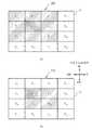
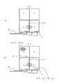
次に実施例3について説明する。まず、引き出し配線を備えるタッチパネルについて説明する。図23(a)は引き出し配線を備えるタッチパネル300を例示する平面図であり、図23(b)は引き出し配線部分を例示する拡大図である(図23(a)の点線部分参照)。 Next, Example 3 will be described. First, a touch panel provided with lead-out wiring will be described. FIG. 23A is a plan view illustrating a
図23(a)及び図23(b)に示すように、第1導電膜2は複数の領域に分割され、領域の各々はプルダウン抵抗と接続するための配線41を備えている。配線41はタッチパネル上辺及び下辺に沿って設けられている。このため、複数の領域のうち領域F21〜F24、及び領域F31〜F34は、各々が列方向に引き出された引き出し配線を有している。つまり図23(b)に示すように、例えば領域F31(第1領域)は主領域F31aと引き出し配線F31bとを備える。引き出し配線F31bは領域F41に隣接して形成されている。言い換えれば、引き出し配線F31bは、領域F41及びF42の間に形成されている。これに対し、領域F41(第2領域)はタッチパネルの下辺に接しているため、引き出し配線は備えていない。なお、領域F21〜F24の引き出し配線はタッチパネルの上辺側に引き出されており、領域F11〜F14は引き出し配線を備えていない。 As shown in FIGS. 23A and 23B, the first
引き出し配線F31bの幅は、主領域F31aの幅よりも小さいため、引き出し配線F31bの抵抗は主領域F31aの抵抗より高くなる。このため、領域F31の抵抗は領域F41の抵抗より高くなる。この結果、領域F31と領域F41とでは、プルダウン抵抗に加わる電位に差が生じる。電位の差を補正するために、例えばプルダウン抵抗の値を変更して領域F31から送信される信号と領域F41から送信される信号とを、同程度の電位とすることがある。また、補正の方法として領域F31から送信される信号にオフセットの電圧を加えることもある。さらに、領域F31から送信される信号に生じるノイズを除去するため、領域F31に接続する場合と、領域F41に接続する場合とで、フィルタの遮蔽周波数を異ならせることがある。具体的には、領域F31に接続する場合は、領域F41に接続する場合よりも、フィルタの通過帯域を低周波側にする。 Since the width of the lead-out wiring F31b is smaller than the width of the main region F31a, the resistance of the lead-out wiring F31b is higher than the resistance of the main region F31a. For this reason, the resistance of the region F31 is higher than the resistance of the region F41. As a result, there is a difference in potential applied to the pull-down resistor between the region F31 and the region F41. In order to correct the potential difference, for example, the value transmitted from the region F31 and the signal transmitted from the region F41 may be set to the same potential by changing the value of the pull-down resistor. Further, as a correction method, an offset voltage may be added to the signal transmitted from the region F31. Furthermore, in order to remove noise generated in the signal transmitted from the region F31, the filter shielding frequency may be different between the case of connection to the region F31 and the case of connection to the region F41. Specifically, when connecting to the region F31, the pass band of the filter is set to the lower frequency side than when connecting to the region F41.
しかしながら、プルダウン抵抗値やフィルタの遮蔽周波数変更の回数が多くなると、それだけタッチパネルの動作が遅くなる可能性がある。特に、フィルタは遮蔽周波数変更後、動作が安定するまでに一定の時間が必要である。従って、複数の領域について順次座標を検出する動作を行うと、タッチパネルの動作が遅くなる可能性がある。 However, as the number of pull-down resistance values and filter shielding frequency changes increases, the operation of the touch panel may be delayed accordingly. In particular, the filter requires a certain time after the change of the shielding frequency until the operation is stabilized. Accordingly, if the operation of sequentially detecting the coordinates for a plurality of areas is performed, the operation of the touch panel may be delayed.
次に実施例3に係るタッチパネルのタッチパネルについて説明する。実施例3に係るタッチパネルでは、複数の領域を行ごとにグループにまとめ、座標検出の制御もグループごとに行う。すなわち、領域F21〜F24の主領域、領域F31〜F34の主領域は、それぞれグループ(第1グループ)を形成する。領域F11〜F14と領域F21〜F24の引き出し配線、及び領域F41〜F44と領域F31〜F34の引き出し配線とは、それぞれグループ(第2グループ)を形成する。 Next, the touch panel of the touch panel according to the third embodiment will be described. In the touch panel according to the third embodiment, a plurality of regions are grouped for each row, and coordinate detection is also controlled for each group. That is, the main regions of the regions F21 to F24 and the main regions of the regions F31 to F34 form a group (first group). The lead lines for the regions F11 to F14 and the regions F21 to F24 and the lead wires for the regions F41 to F44 and the regions F31 to F34 form a group (second group).
次に、実施例3に係るタッチパネルの領域選択部及びフィルタ部について説明する。図24は実施例3に係るタッチパネルの領域選択部及びフィルタ部を例示するブロック図である(図2参照)。 Next, the area selection unit and the filter unit of the touch panel according to the third embodiment will be described. FIG. 24 is a block diagram illustrating a region selection unit and a filter unit of the touch panel according to the third embodiment (see FIG. 2).
図24に示すように、領域選択部20は複数のマルチプレクサ30,32,34及び36を備える。フィルタ部22は複数のフィルタ42,44,46及び48を備える。フィルタ42〜48の各々はローパスフィルタである。 As shown in FIG. 24, the
領域F11〜F44は行ごとにグループを形成し、複数のグループの各々は、複数のマルチプレクサ30〜36の各々に接続されている。マルチプレクサ30〜36の各々は、フィルタ42〜44の各々に接続されている。マルチプレクサは、各領域が送信する信号、及び制御部16が送信するセレクト信号を受信する(図2参照)。マルチプレクサ30は、セレクト信号により、領域F11〜F14の各領域が送信する信号から、座標の検出を行う領域の信号を選択することができる。マルチプレクサ32〜36についても同様である。つまり、領域選択部20は行ごとにまとめられたグループから、領域を選択することができる。 The regions F11 to F44 form a group for each row, and each of the plurality of groups is connected to each of the plurality of
また、第1グループに接続されたフィルタ44及び46は、第2グループに接続されたフィルタ42及び48よりも通過帯域が低周波側にある。つまり、第1グループと第2グループとは、互いに遮蔽周波数が異なる複数のフィルタに接続される。 Further, the
次に、実施例3に係るタッチパネルの制御について説明する。図25は実施例3に係るタッチパネルの制御を例示するフローチャートである。 Next, control of the touch panel according to the third embodiment will be described. FIG. 25 is a flowchart illustrating the control of the touch panel according to the third embodiment.
図25に示すように、まず制御部16は1行目においてタッチONチェックを行う(ステップS120)。ステップS120の後、制御部16は、1行目の各領域においてX座標及びY座標の検出を行う(ステップS121)。つまり、制御部16は図4に示したステップS4〜S9の制御を行う。 As shown in FIG. 25, first, the control unit 16 performs a touch-on check on the first line (step S120). After step S120, the control unit 16 detects the X coordinate and the Y coordinate in each area of the first row (step S121). That is, the control unit 16 performs the control of steps S4 to S9 shown in FIG.
ステップS121の後、制御部16は2行目においてタッチONチェックを行う(ステップS122)。ステップS122の後、制御部16は、2行目の各領域においてX座標及びY座標の検出を行う(ステップS123)。ステップS123の後、3行目及び4行目について、同様の制御を行い(ステップS124〜S127)、制御は終了する。 After step S121, the control unit 16 performs a touch-on check on the second line (step S122). After step S122, the control unit 16 detects the X coordinate and the Y coordinate in each area of the second row (step S123). After step S123, the same control is performed for the third and fourth lines (steps S124 to S127), and the control ends.
実施例3によれば、複数の領域は、引き出し配線を含むグループと、引き出し配線を含まないグループとにまとめられ、各グループは遮蔽帯域の異なるフィルタに接続される。制御部16は上記のグループごとに座標を検出する。従って、領域ごとに電位差を補正しなくてよく、またフィルタの遮蔽周波数を変更しなくてよいため、タッチパネルの高速化が可能となる。 According to the third embodiment, the plurality of regions are grouped into a group including the lead wiring and a group not including the lead wiring, and each group is connected to a filter having a different shielding band. The control part 16 detects a coordinate for every said group. Therefore, it is not necessary to correct the potential difference for each region, and it is not necessary to change the shielding frequency of the filter, so that the speed of the touch panel can be increased.
図24に示すように、実施例3では、グループごとに異なるフィルタに接続しているが、構成はこれに限定されない。例えば図23(a)に示すように、領域F21〜F24、及び領域F31〜F34はいずれも引き出し配線を備えているため、抵抗は高くなる。従って、領域F21〜F34を同じフィルタに接続してもよい。また、いずれも引き出し配線を備えていない領域F11〜F14及び領域F41〜F44を同じフィルタに接続してもよい。これにより、フィルタの数を少なくできるため、タッチパネルの小型化、及び低コスト化が可能となる。図23(a)に示すように、実施例3では引き出し配線を列方向に引き出しているが、行方向に引き出してもよく、この場合は列ごとにまとめてグループとする。また、引き出し配線は行列以外の方向に引き出されていてもよい。 As shown in FIG. 24, in Example 3, each group is connected to a different filter, but the configuration is not limited to this. For example, as shown in FIG. 23A, since the regions F21 to F24 and the regions F31 to F34 are all provided with lead-out wiring, the resistance becomes high. Accordingly, the regions F21 to F34 may be connected to the same filter. Moreover, you may connect the area | regions F11-F14 and the area | regions F41-F44 which are not provided with the drawing-out wiring to the same filter. Thereby, since the number of filters can be reduced, it is possible to reduce the size and cost of the touch panel. As shown in FIG. 23A, in the third embodiment, the lead-out wiring is led out in the column direction. However, the lead-out wiring may be led out in the row direction. Further, the lead wiring may be drawn in a direction other than the matrix.
次に実施例4について説明する。実施例4においても、例えば図23(a)のように、第1導電膜2は複数の領域に分割され、複数の領域のうち領域F21〜F24、及び領域F31〜F34は、各々が列方向に引き出された引き出し配線を有している。領域F11〜F44は、行ごとにグループにまとめられている。すなわち、領域F21〜F24の主領域、領域F31〜F34の主領域は、それぞれグループ(第1グループ)を形成する。領域F11〜F14と領域F21〜F24の引き出し配線、及び領域F41〜F44と領域F31〜F34の引き出し配線とは、それぞれグループ(第2グループ)を形成する。 Next, Example 4 will be described. Also in Example 4, for example, as shown in FIG. 23A, the first
次に実施例4に係る領域選択部の構成について説明する。図26(a)から図26(c)は実施例4に係る領域選択部を例示する図である。各図においては、領域選択部20のうち、領域F11〜F14に係る部分を図示している。 Next, the configuration of the area selection unit according to the fourth embodiment will be described. FIG. 26A to FIG. 26C are diagrams illustrating the area selection unit according to the fourth embodiment. In each figure, the part which concerns on the area | regions F11-F14 among the area |
図26(a)に示すように、領域選択部20のマルチプレクサ30は領域F11〜F14に接続されている。すなわち、領域は行ごとにグループにまとめられ、1つのマルチプレクサに接続されている。またマルチプレクサ30は、第1導電膜2と第2導電膜4とが接触したことに応じて領域F11〜F14が送信する信号、及び制御部16が送信するセレクト信号を受信する。また、領域F11〜F14の各々が送信する信号は、複数のダイオード50の各々に入力する。複数のダイオード50の出力側はノード51により1つの配線にまとめられている。言い換えればノード51は、第1導電膜2と第2導電膜4とが接触したことに応じて領域F11〜F14から送信される信号を1つの信号(以下「結束信号」)として結合する結合手段として機能する。ダイオード50は、出力側の信号が入力側に逆流することを抑制する。例えばダイオード50は、領域F11が送信する信号が逆流して領域F12〜F14に接続された配線に流れることを抑制する。領域F11〜F14が送信する信号は、ダイオード50を介してフィルタ部22に入力し、さらに制御部16に入力する(図2参照)。 As shown in FIG. 26A, the
制御部16は、結束信号を受信することで、領域F11〜F14のいずれかにおいて第1導電膜2と第2導電膜4とが接触したことを検知できる。言い換えれば、制御部16は結束信号を受信したことに応じて、領域F11〜F14からなるグループにおいて第1導電膜2と第2導電膜4とが接触したと判断する。 The control part 16 can detect that the 1st electrically
また、領域F21〜F24、領域F31〜F34、及び領域F41〜F44もグループにまとめられ、それぞれ異なるマルチプレクサ及びフィルタに接続されている。 The regions F21 to F24, the regions F31 to F34, and the regions F41 to F44 are also grouped and connected to different multiplexers and filters, respectively.
次に、実施例4に係るタッチパネルの制御について説明する。図27は実施例4に係るタッチパネルの制御を例示するフローチャートである。 Next, control of the touch panel according to the fourth embodiment will be described. FIG. 27 is a flowchart illustrating the control of the touch panel according to the fourth embodiment.
図27に示すように、制御部16はm=1とする(ステップS130)。ステップS130の後、制御部16はm列目においてタッチONチェックを行う(ステップS131)。ステップS131の後、制御部16はm列目においてタッチONか判断する(ステップS132)。すなわち制御部16は、複数のグループの各々ごとに、第1導電膜2と第2導電膜4とが接触したか判断する。Noの場合、制御は後述するステップS139に進む。 As shown in FIG. 27, the control unit 16 sets m = 1 (step S130). After step S130, the control unit 16 performs a touch ON check in the m-th column (step S131). After step S131, the control unit 16 determines whether the touch is ON in the m-th column (step S132). That is, the control unit 16 determines whether the first
Yesの場合、制御部16はn=1とする(ステップS133)。ステップS133の後、制御部16は領域FmnにおいてタッチONチェックを行い(ステップS134)、領域FmnにおいてタッチONか判断する(ステップS135)。 In the case of Yes, the control unit 16 sets n = 1 (step S133). After step S133, the control unit 16 performs a touch ON check in the area Fmn (step S134), and determines whether the touch is ON in the area Fmn (step S135).
Yesの場合、制御部16は、領域Fmnにおいて座標を検出する(ステップS136)。ステップS136の後、又はステップS135においてNoの場合、制御部16はn=MAXか判断する(ステップS137)。Yesの場合、制御部16はn=n+1とし(ステップS138)、制御はステップS134に戻る。すなわち、ステップS132においてタッチONか判断されたm列目に属する領域のうち、1つ後の行の領域においてステップS134〜S136の制御が行われることになる。 In the case of Yes, the control part 16 detects a coordinate in the area | region Fmn (step S136). After step S136 or in the case of No in step S135, the control unit 16 determines whether n = MAX (step S137). In the case of Yes, the control unit 16 sets n = n + 1 (step S138), and the control returns to step S134. That is, the control in steps S134 to S136 is performed in the area of the next row among the areas belonging to the m-th column for which it is determined in step S132 that the touch is ON.
ステップS137においてNoの場合、制御部16はm=MAXか判断する(ステップS139)。Yesの場合、制御部16はm=m+1とし(ステップS140)、制御はステップS131に戻る。すなわち、ステップS132においてタッチONか判断された列より、1つ後の列においてステップS131〜S139の制御が行われることになる。ステップS139においてYesの場合、制御は終了する。 In the case of No in step S137, the control unit 16 determines whether m = MAX (step S139). In the case of Yes, the control unit 16 sets m = m + 1 (step S140), and the control returns to step S131. That is, the control in steps S131 to S139 is performed in the next row from the row in which it is determined in step S132 that the touch is ON. If Yes in step S139, the control ends.
実施例4によれば、制御部16は複数のグループの各々ごとに第1導電膜2と第2導電膜4とが接触したか判断し(図27のステップS131、及びS132においてYesの場合)、接触したグループにおいては、座標を検出する動作を行う(ステップS134)。また制御部16は、第1導電膜2と第2導電膜4とが接触していないグループにおいては、座標を検出する動作を行わない(ステップS132においてNoの場合)。このため、各領域について順次制御を行う場合よりも、タッチONチェックや座標検出の制御の回数が少なくなる。従って、タッチパネルの高速化が可能となる。 According to the fourth embodiment, the control unit 16 determines whether the first
特に、図23(a)及び図23(b)のように、引き出し配線が形成されている場合、複数の領域を引き出し配線を含むグループと、引き出し配線を含まないグループとにまとめて、グループごとに遮蔽周波数が異なるフィルタに接続することができる。これにより、領域ごとに電位差を補正しなくてよく、またフィルタの遮蔽周波数を変更しなくてよいため、タッチパネルのさらなる高速化が可能となる。 In particular, as shown in FIGS. 23A and 23B, when lead-out wiring is formed, a plurality of regions are grouped into a group including the lead-out wiring and a group not including the lead-out wiring, and each group is grouped. It is possible to connect to filters having different shielding frequencies. Thereby, since it is not necessary to correct | amend an electric potential difference for every area | region and it is not necessary to change the shielding frequency of a filter, the further speed-up of a touch panel is attained.
また、ノード51はグループを構成する領域の各々から送信される信号を1つの信号として結合し、1つに結合された信号が送信されたことに応じて、制御部16はグループにおいて第1導電膜2と第2導電膜4とが接触したと判断する。従って、簡単な構成により、自動的に第1導電膜2と第2導電膜4とが接触したグループを判断でき、座標を検出する動作を行うことができる。 In addition, the
実施例4では複数の領域を行ごとにグループにまとめた例について説明したが、グループの例はこれに限定されない。例えば列ごとにグループとしてもよい。つまり、複数のグループの各々は、複数の領域のうち一部の領域からなる。また、複数の領域は、引き出し配線を含むグループと、引き出し配線を含まないグループとにまとめられるとしたが、これに限定されない。 In the fourth embodiment, the example in which a plurality of regions are grouped into rows is described. However, the group example is not limited to this. For example, it may be a group for each column. That is, each of the plurality of groups includes a part of the plurality of regions. Further, although the plurality of regions are grouped into a group including the lead wiring and a group not including the lead wiring, the present invention is not limited to this.
次に実施例4の変形例について説明する。図26(b)及び図26(c)は実施例4の変形例に係る領域選択部を例示する図である。 Next, a modification of the fourth embodiment will be described. FIG. 26B and FIG. 26C are diagrams illustrating a region selection unit according to a modification of the fourth embodiment.
図26(b)に示すように、ダイオード50の代わりに半導体スイッチ52を用いてもよい。この場合、半導体スイッチ52には制御部16から制御信号が入力する。 As shown in FIG. 26B, a
図26(c)に示すように、ダイオード50の代わりに電磁開閉器54を用いてもよい。この場合も、電磁開閉器54には制御部16から制御信号が入力する。 As shown in FIG. 26 (c), an
次に実施例5について説明する。図28(a)は実施例5に係るタッチパネルの引き出し配線部分を例示する拡大図である(図23(a)の点線部分参照)。 Next, Example 5 will be described. FIG. 28A is an enlarged view illustrating the lead-out wiring portion of the touch panel according to the fifth embodiment (see the dotted line portion in FIG. 23A).
図28(a)に示すように、領域F31は主領域F31aと引き出し配線F31bとからなる。引き出し配線F31bは、領域F41と領域F42との間に位置している。 As shown in FIG. 28A, the region F31 includes a main region F31a and a lead-out wiring F31b. The lead wiring F31b is located between the region F41 and the region F42.
ここで、図中の斜線で示すように、領域F41、F42及び引き出し配線F31bにおいて、第1導電膜2と第2導電膜4とが接触した場合を考える。これは、例えば指等により、第1導電膜2のうち領域F41,引き出し配線F31b、及び領域F42にまたがった箇所がタッチされた場合である。このとき、ユーザは1点を入力することを意図していても、3点に入力があったと判断されることがある。従って領域F31において入力があったと判断され、タッチパネルが誤作動を起こす可能性がある。 Here, consider the case where the first
実施例5に係るタッチパネルは、各領域における座標の差が所定の範囲内である場合、1点が入力されたと判断して、座標を出力する。より詳しくはフローチャートを参照して説明する。図29は実施例5に係るタッチパネルの制御を例示するフローチャートである。 The touch panel according to the fifth embodiment determines that one point has been input when the difference in coordinates in each region is within a predetermined range, and outputs the coordinates. This will be described in detail with reference to a flowchart. FIG. 29 is a flowchart illustrating control of the touch panel according to the fifth embodiment.
図29に示すように、まず制御部16は(図2参照)、領域FmnにおいてタッチONチェックを行い(ステップS141)、領域FmnにおいてタッチONか判断する(ステップS142)。すなわち制御部16は、複数の領域ごとに第1導電膜2と第2導電膜4とが接触したか判断する。 As shown in FIG. 29, first, the control unit 16 (see FIG. 2) performs a touch ON check in the area Fmn (step S141), and determines whether the touch is ON in the area Fmn (step S142). That is, the control unit 16 determines whether the first
Yesの場合、制御部16は、領域Fmnにおいて第1導電膜2と第2導電膜4とが接触した点のX座標及びY座標を検出する(ステップS143)。ステップS143の後、制御部16は、検出された複数のX座標及びY座標が、それぞれ所定の範囲内にあるか判断する(ステップS144)。Yesの場合、制御部16はステップ144において所定の範囲内にあるか判断した座標に基づき、座標を検出して、検出した座標を出力する(ステップS145)。ステップS145の後、又はステップS142においてNoの場合、及びステップS144においてNoの場合、制御は終了する。 In the case of Yes, the control unit 16 detects the X coordinate and the Y coordinate of the point where the first
ステップS144及びS145の制御について、図28(a)の例を参照し具体的に説明する。領域F41(第1領域)において検出されたX座標及びY座標(第1の座標)をそれぞれ、X(F41)、Y(F41)とする。同様に、領域F42(第2領域)において検出された座標(第2の座標)をX(F42)、Y(F42)とする。また、領域F31(第3領域)の引き出し配線F31bにおいて検出された座標(第3の座標)をX(F31b)、Y(F31b)とする。 The control in steps S144 and S145 will be specifically described with reference to the example of FIG. The X coordinate and Y coordinate (first coordinate) detected in the region F41 (first region) are respectively referred to as X (F41) and Y (F41). Similarly, the coordinates (second coordinates) detected in the area F42 (second area) are X (F42) and Y (F42). Also, the coordinates (third coordinates) detected in the lead-out wiring F31b in the area F31 (third area) are X (F31b) and Y (F31b).
ステップS144における所定の範囲をαとすると、制御部16は|X(F41)−X(F42)|<α、|X(F42)−X(F31b)|<α、|Y(F41)−Y(F42)|<α、及び|Y(F42)−Y(F31b)|<αであるか判断する(ステップS144)。検出された座標が、上記の関係を満たす場合、制御部16は1点において入力がされたと判断し、X(F41)、X(F31b)及びX(F42)に基づき、X座標(第4の座標)を出力する。また制御部16は、Y(F41)、Y(F31b)及びY(F42)に基づき、Y座標(第4の座標)を出力する(ステップS145)。すなわち、制御部16は検出された3つの座標に基づき、1つの座標を出力する。 If the predetermined range in step S144 is α, the control unit 16 | X (F41) −X (F42) | <α, | X (F42) −X (F31b) | <α, | Y (F41) −Y It is determined whether (F42) | <α and | Y (F42) −Y (F31b) | <α (step S144). When the detected coordinates satisfy the above relationship, the control unit 16 determines that an input is made at one point, and based on X (F41), X (F31b), and X (F42), the X coordinate (fourth Coordinate). In addition, the control unit 16 outputs a Y coordinate (fourth coordinate) based on Y (F41), Y (F31b), and Y (F42) (step S145). That is, the control unit 16 outputs one coordinate based on the detected three coordinates.
実施例5によれば、引き出し配線を含む複数の領域において座標が検出された場合でも、検出された座標に基づき定めた座標を出力する。従って、タッチパネルの座標検出の精度が向上する。特に引き出し配線での入力は無視し、1点において入力があったと判断されるため、誤作動を抑制することが可能となる。 According to the fifth embodiment, even when coordinates are detected in a plurality of regions including the lead wiring, coordinates determined based on the detected coordinates are output. Therefore, the accuracy of coordinate detection of the touch panel is improved. In particular, the input at the lead-out wiring is ignored, and it is determined that there is an input at one point, so that malfunction can be suppressed.
ステップS145において、制御部16は例えば領域F41において検出された座標と領域F42において検出された座標との、平均の座標を出力する。また、制御部16は平均以外の座標を出力してもよい。また、X座標とY座標とで、共に所定の範囲をαとして説明したが、X座標とY座標とで所定の範囲が異なっていてもよい。 In step S145, the control unit 16 outputs, for example, average coordinates of the coordinates detected in the region F41 and the coordinates detected in the region F42. Further, the control unit 16 may output coordinates other than the average. In addition, although the predetermined range is described as α for both the X coordinate and the Y coordinate, the predetermined range may be different for the X coordinate and the Y coordinate.
次に実施例5の変形例について説明する。図28(b)は実施例5の変形例に係るタッチパネルの引き出し配線部分を例示する拡大図である(図23(a)の点線部分参照)。 Next, a modification of the fifth embodiment will be described. FIG. 28B is an enlarged view illustrating the lead-out wiring portion of the touch panel according to the modification of the fifth embodiment (see the dotted line portion in FIG. 23A).
図28(b)に網掛けで示すように、図28(a)において説明した領域F41、F42、領域F31の引き出し配線F31bに加えて、さらに領域F31の主領域F31aでも第1導電膜2と第2導電膜4とが接触した場合を考える。この場合、図中の黒点で示すように、斜線の領域と、網掛けの領域とにおいて検出された座標の平均の座標が出力されることがある。この場合、網掛けの領域で実際に入力が行われた点の座標が出力されない。従って、ユーザの意図しない入力がされたと判断され、タッチパネルが誤作動する可能性がある。実施例5の変形例では、実際に入力が行われた点の座標を出力する。より詳しくは図29に示したフローチャート、及び図28(b)の例を参照して説明する。 As shown by shading in FIG. 28B, in addition to the lead lines F31b in the regions F41 and F42 and the region F31 described in FIG. Consider the case where the second
図29のステップS141及びS142は既述したので説明を省略する。ステップS142の後、制御部16は、X(F41)、Y(F41)、X(F42)、Y(F42)、X(F31b)、Y(F31b)、及び領域F31の主領域F31aにおいて第1導電膜2と第2導電膜4とが接触した点の座標であるX(F31a)、Y(F31a)(第5の座標)を検出する(ステップS143)。 Since steps S141 and S142 in FIG. 29 have already been described, description thereof will be omitted. After step S142, the control unit 16 performs the first operation in X (F41), Y (F41), X (F42), Y (F42), X (F31b), Y (F31b), and the main region F31a of the region F31. X (F31a) and Y (F31a) (fifth coordinate) that are the coordinates of the point where the
ステップS143の後、制御部16は検出された複数のX座標及びY座標が、それぞれ所定の範囲内にあるか判断する(ステップS144)。Yesの場合、図28(a)及び図29で説明したように、制御部16は領域F41、F42、領域F31の引き出し配線F31bにおいて検出された座標に基づき1つの座標を検出する。検出されたX座標及びY座標をそれぞれX(F41,F42)、Y(F41,F42)とする。また制御部16は、図28(b)の黒点の座標x、y(第6の座標)を検出する。xはX(F31a)とX(F41,F42)との平均、yはY(F31a)とY(F41,F42)との平均である。 After step S143, the control unit 16 determines whether the detected plurality of X coordinates and Y coordinates are within a predetermined range (step S144). In the case of Yes, as described with reference to FIGS. 28A and 29, the control unit 16 detects one coordinate based on the coordinates detected in the lead-out wiring F31b of the regions F41, F42 and F31. The detected X coordinate and Y coordinate are X (F41, F42) and Y (F41, F42), respectively. Further, the control unit 16 detects the coordinates x and y (sixth coordinates) of the black point in FIG. x is an average of X (F31a) and X (F41, F42), and y is an average of Y (F31a) and Y (F41, F42).
さらに制御部16は、主領域F31aにおいて実際に第1導電膜2と第2導電膜4とが接触した点の座標であるX(F31a)、Y(F31a)を、X(F41,F42)、x、Y(F41,F42)及びyに基づき検出し、出力する(ステップS145)。具体的には、X(F41a)=2x−X(F41,F42)、及びY(F41a)=2y−Y(F41,F42)とする。ステップS145の後、制御は終了する。 Further, the control unit 16 converts X (F31a) and Y (F31a), which are the coordinates of the actual contact point between the first
実施例5の変形例によれば、図28(b)に示すように2箇所において座標が検出された場合でも、実際に入力があった点の座標を出力することができる。従って、タッチパネルの座標検出の精度が向上し、誤作動を抑制することが可能となる。 According to the modification of the fifth embodiment, as shown in FIG. 28 (b), even when coordinates are detected at two locations, the coordinates of the points actually inputted can be output. Therefore, the accuracy of coordinate detection of the touch panel is improved, and malfunctions can be suppressed.
以上、本発明の実施例について詳述したが、本発明はかかる特定の実施例に限定されるものではなく、特許請求の範囲に記載された本発明の要旨の範囲内において、種々の変形・変更が可能である。 Although the embodiments of the present invention have been described in detail above, the present invention is not limited to such specific embodiments, and various modifications and changes can be made within the scope of the gist of the present invention described in the claims. It can be changed.
第1導電膜 2
第2導電膜 4
電極 6,8,10,12
制御部 16
電極制御部 18
領域選択部 20
フィルタ部 22
マルチプレクサ 30,32,34,36
プルダウン抵抗 40
フィルタ 42,44,46,48
ダイオード 50
ノード 51
タッチパネル 100,200,210,300First
Second
Control unit 16
Pull-
Claims (22)
Translated fromJapanese前記第1導電膜と対向し、かつ離間する第2導電膜と、
前記第2導電膜が備える互いに対向する一組の電極と、
前記第2導電膜が備え、互いに対向する、前記一組の電極とは別の一組の電極と、
前記第1導電膜と前記第2導電膜とが接触したか、前記領域ごとに判断し、
前記第1導電膜と前記第2導電膜とが接触した場合、前記一組の電極に電圧を印加することで、前記第1導電膜と前記第2導電膜とが接触した点のX座標又はY座標のいずれか一方を検出し、
前記複数の領域の各々において前記X座標又はY座標のいずれか一方を検出した後に、前記一組の電極に印加した電圧を除去し、
前記電圧を除去した後に、前記別の一組の電極に電圧を印加することで、前記複数の領域の各々において前記X座標又はY座標のいずれか他方を検出する制御部と、を具備するタッチパネル。A first conductive film divided into a plurality of regions that are insulated from each other;
A second conductive film facing and spaced apart from the first conductive film;
A pair of opposing electrodes included in the second conductive film;
A set of electrodes different from the set of electrodes provided in the second conductive film and facing each other;
For each region, determine whether the first conductive film and the second conductive film are in contact with each other,
When the first conductive film and the second conductive film are in contact with each other, by applying a voltage to the set of electrodes, the X coordinate of the point where the first conductive film and the second conductive film are in contact or Detect one of the Y coordinates,
After detecting either the X coordinate or the Y coordinate in each of the plurality of regions, the voltage applied to the set of electrodes is removed,
A control unit that detects the other of the X coordinate and the Y coordinate in each of the plurality of regions by applying a voltage to the another set of electrodes after removing the voltage. .
前記複数の領域のうち前記接触した領域とは別の領域において前記第1導電膜と前記第2導電膜とが接触したか判断する請求項1記載のタッチパネル。When the first conductive film and the second conductive film are in contact with each other in any of the plurality of regions, the control unit detects either the X coordinate or the Y coordinate in the contacted region. rear,
The touch panel according to claim 1, wherein it is determined whether the first conductive film and the second conductive film are in contact with each other in a region different from the contacted region among the plurality of regions.
前記第1導電膜と対向し、かつ離間する第2導電膜と、
前記第1導電膜と前記第2導電膜とが接触した点の座標を出力した場合、前記座標を出力した動作の次の動作においては前記複数の領域のうち前記動作で座標を出力した領域、及び前記動作で座標を出力した領域の周辺の領域において、前記第1導電膜と前記第2導電膜とが接触した点の座標を検出し、
前記動作で座標を出力した場合、前記複数の領域のうち、前記次の動作で座標を検出した領域、及び前記周辺の領域以外の領域においては、前記座標を検出しない制御部と、を具備するタッチパネル。A first conductive film divided into a plurality of regions that are insulated from each other;
A second conductive film facing and spaced apart from the first conductive film;
When outputting the coordinates of the point where the first conductive film and the second conductive film are in contact with each other, in the operation following the operation of outputting the coordinates, the region in which the coordinates are output in the operation among the plurality of regions, And detecting the coordinates of the point where the first conductive film and the second conductive film are in contact with each other in a region around the region where the coordinates are output in the operation,
When the coordinates are output by the operation, a control unit that does not detect the coordinates in the region other than the peripheral region in the region where the coordinate is detected in the next operation among the plurality of regions is provided. Touch panel.
前記第1導電膜と対向し、かつ離間する第2導電膜と、
前記複数の領域のうち第1領域の主領域からなる第1グループと、前記第1領域の引き出し配線及び前記複数の領域のうち第2領域からなる第2グループと、の各々ごとに前記第1導電膜と前記第2導電膜とが接触した点の座標を検出する制御部と、を具備するタッチパネル。A first conductive film divided into a plurality of regions that are insulated from each other;
A second conductive film facing and spaced apart from the first conductive film;
Of each of the plurality of regions, each of the first group including a main region of the first region, and each of the first group including the lead wiring of the first region and the second group including the second region of the plurality of regions. And a control unit that detects coordinates of a point where the conductive film and the second conductive film are in contact with each other.
前記引き出し配線は前記行又は列のいずれか他方の方向に引き出されている請求項7記載のタッチパネル。The first group and the second group are groups in which the plurality of regions are grouped together in either row or column,
The touch panel according to claim 7, wherein the lead-out wiring is led out in the other direction of the row or the column.
前記第1導電膜と対向し、かつ離間する第2導電膜と、
各々が前記複数の領域のうち一部の領域からなる複数のグループの各々ごとに、前記第1導電膜と前記第2導電膜とが接触したか判断し、
前記複数のグループのうち前記第1導電膜と前記第2導電膜とが接触したグループにおいて、前記第1導電膜と前記第2導電膜とが接触した点の座標を検出する動作を行い、
かつ前記複数のグループのうち、前記第1導電膜と前記第2導電膜とが接触していないグループにおいては、前記座標を検出する動作を行わない制御部と、を具備するタッチパネル。A first conductive film divided into a plurality of regions that are insulated from each other;
A second conductive film facing and spaced apart from the first conductive film;
Determining whether the first conductive film and the second conductive film are in contact with each of a plurality of groups each consisting of a part of the plurality of regions;
In the group in which the first conductive film and the second conductive film are in contact among the plurality of groups, an operation of detecting the coordinates of the point where the first conductive film and the second conductive film are in contact with each other is performed.
A touch panel comprising: a control unit that does not perform the operation of detecting the coordinates in a group in which the first conductive film and the second conductive film are not in contact among the plurality of groups.
前記引き出し配線は前記行又は列のいずれか他方の方向に引き出されている請求項9又は10記載のタッチパネル。The first group and the second group are groups in which the plurality of regions are grouped together in either row or column,
The touch panel according to claim 9 or 10, wherein the lead-out wiring is led out in the other direction of the row or the column.
前記制御部は前記結合手段により結合された前記1つの信号を受信したことに応じて、前記一部の領域からなるグループにおいて前記第1導電膜と前記第2導電膜とが接触したと判断する請求項9から12いずれか一項記載のタッチパネル。Coupling that combines signals transmitted from each of the partial regions constituting each of the plurality of groups as one signal in response to contact between the first conductive film and the second conductive film With means,
The control unit determines that the first conductive film and the second conductive film are in contact with each other in the group consisting of the partial regions in response to receiving the one signal combined by the combining unit. The touch panel according to any one of claims 9 to 12.
前記第1導電膜と対向し、かつ離間する第2導電膜と、
前記複数の領域のうち、第1領域と、第2領域と、前記第1領域及び前記第2領域との間に位置する第3領域の引き出し配線と、において前記第1導電膜と前記第2導電膜とが接触した場合であって、
前記第1領域において前記第1導電膜と前記第2導電膜とが接触した点の座標である第1の座標と、前記第2領域において前記第1導電膜と前記第2導電膜とが接触した点の座標である第2の座標との差、
及び前記第1の座標と、前記第3領域の引き出し配線において前記第1導電膜と前記第2導電膜とが接触した点の座標である第3の座標との差が、それぞれ所定の範囲内である場合、
前記第1の座標及び前記第2の座標とに基づき、第4の座標を出力する制御部と、を具備するタッチパネル。A first conductive film divided into a plurality of regions that are insulated from each other;
A second conductive film facing and spaced apart from the first conductive film;
Of the plurality of regions, the first conductive film and the second region in the first region, the second region, and the third region extraction wiring located between the first region and the second region. When the conductive film is in contact with
The first coordinates, which are the coordinates of the point where the first conductive film and the second conductive film are in contact with each other in the first region, and the first conductive film and the second conductive film are in contact with each other in the second region. The difference from the second coordinate, which is the coordinate of the point
And the difference between the first coordinate and the third coordinate which is the coordinate of the point where the first conductive film and the second conductive film are in contact with each other in the lead wiring of the third region is within a predetermined range. If it is,
And a control unit that outputs a fourth coordinate based on the first coordinate and the second coordinate.
前記第4の座標と前記第6の座標とに基づき、前記第5の座標を出力する請求項14又は15記載のタッチパネル。Based on the fifth coordinate, which is the coordinate of the point where the first conductive film and the second conductive film are in contact with each other in the main region of the third region, and the fourth coordinate, Detect the coordinates of
The touch panel according to claim 14 or 15, wherein the fifth coordinate is output based on the fourth coordinate and the sixth coordinate.
前記第1導電膜と前記第2導電膜とが接触した場合、前記第2導電膜に設けられた、互いに対向する一組の電極に電圧を印加することで、前記第1導電膜と前記第2導電膜とが接触した点のX座標又はY座標のいずれか一方を検出するステップと、
前記X座標又はY座標のいずれか一方を検出するステップを前記複数の領域の各々において行った後に、前記一組の電極に印加した電圧を除去するステップと、
前記電圧を除去するステップの後に、互いに対向する、前記一組の電極とは別の一組の電極に電圧を印加することで、前記複数の領域の各々において前記X座標又はY座標のいずれか他方を検出するステップと、を有するタッチパネルの座標検出方法。Determining, for each of the regions, whether a first conductive film divided into a plurality of regions insulated from each other and a second conductive film facing and spaced apart from the first conductive film are in contact with each other;
When the first conductive film and the second conductive film are in contact with each other, a voltage is applied to a pair of electrodes provided in the second conductive film facing each other, whereby the first conductive film and the second conductive film are applied. 2 detecting either the X coordinate or the Y coordinate of the point in contact with the conductive film;
Removing the voltage applied to the set of electrodes after performing the step of detecting either the X coordinate or the Y coordinate in each of the plurality of regions;
After the step of removing the voltage, one of the X coordinate and the Y coordinate is applied to each of the plurality of regions by applying a voltage to a pair of electrodes opposite to the pair of electrodes facing each other. Detecting the other, a touch panel coordinate detection method.
前記出力するステップの後に、前記出力するステップにおいて座標を出力した領域、及び前記座標を出力した領域の周辺の領域で、前記第1導電膜と前記第2導電膜とが接触した点の座標を検出するステップと、を有し、
前記座標を出力するステップにおいて座標を出力した場合、前記複数の領域のうち、前記検出動作で座標を検出した領域、及び前記周辺の領域以外の領域においては、前記座標を検出しない、タッチパネルの座標検出方法。Outputting coordinates of a point where a first conductive film divided into a plurality of regions insulated from each other and a second conductive film facing and spaced apart from the first conductive film are in contact with each other;
After the outputting step, the coordinates of the point where the first conductive film and the second conductive film are in contact with each other in the region where the coordinates are output in the outputting step and the region around the region where the coordinates are output. Detecting, and
When coordinates are output in the step of outputting coordinates, the coordinates of the touch panel that do not detect the coordinates in the areas other than the area where the coordinates are detected by the detection operation and the peripheral area among the plurality of areas. Detection method.
前記座標を検出する動作を前記第1領域の引き出し配線及び前記複数の領域のうち第2領域からなる第2グループにおいて行うステップと、を有するタッチパネルの座標検出方法。The operation of detecting the coordinates of the point where the first conductive film divided into a plurality of regions insulated from each other and the second conductive film facing and spaced apart from the first conductive film is in contact with the plurality of regions. A step performed in a first group including a main area of the first area;
A coordinate detection method for a touch panel, comprising: performing an operation of detecting the coordinates in a second group including a lead wiring of the first region and a second region of the plurality of regions.
前記複数のグループのうち前記第1導電膜と前記第2導電膜とが接触したグループにおいて、前記第1導電膜と前記第2導電膜とが接触した点の座標を検出する動作を行うステップと、を有し、
前記複数のグループのうち、前記第1導電膜と前記第2導電膜とが接触していないグループにおいては、前記座標を検出する動作を行わないタッチパネルの座標検出方法。A first conductive film that is divided into a plurality of regions that are insulated from each other and a second conductive film that is opposed to and separate from the first conductive film are in contact with each other, or each is a part of the plurality of regions Determining for each of a plurality of groups comprising:
Performing an operation of detecting coordinates of a point at which the first conductive film and the second conductive film are in contact with each other in a group in which the first conductive film and the second conductive film are in contact among the plurality of groups; Have
The touch panel coordinate detection method which does not perform the operation | movement which detects the said coordinate in the group in which the said 1st conductive film and the said 2nd conductive film do not contact among these groups.
前記第1領域において前記第1導電膜と前記第2導電膜とが接触した点の座標である第1の座標と、前記第2領域において前記第1導電膜と前記第2導電膜とが接触した点の座標である第2の座標との差、
及び前記第1の座標と、前記第3領域の引き出し配線において前記第1導電膜と前記第2導電膜とが接触した点の座標である第3の座標との差が、それぞれ所定の範囲内であるか判断するステップと、
前記第1の座標と前記第2の座標との差、及び前記第1の座標と前記第3の座標との差が前記所定の範囲内である場合、前記第1の座標及び前記第2の座標とに基づき、第4の座標を出力するステップと、を有するタッチパネルの座標検出方法。A first conductive film that is divided into a plurality of regions that are insulated from each other, and a second conductive film that is opposed to and spaced apart from the first conductive film are a first region and a second region among the plurality of regions. And a lead-out line in a third region located between the first region and the second region,
The first coordinates, which are the coordinates of the point where the first conductive film and the second conductive film are in contact with each other in the first region, and the first conductive film and the second conductive film are in contact with each other in the second region. The difference from the second coordinate, which is the coordinate of the point
And the difference between the first coordinate and the third coordinate which is the coordinate of the point where the first conductive film and the second conductive film are in contact with each other in the lead wiring of the third region is within a predetermined range. A step of determining whether or not
When the difference between the first coordinate and the second coordinate and the difference between the first coordinate and the third coordinate are within the predetermined range, the first coordinate and the second coordinate Outputting a fourth coordinate based on the coordinate, and a coordinate detection method for the touch panel.
Priority Applications (7)
| Application Number | Priority Date | Filing Date | Title |
|---|---|---|---|
| JP2009287101AJP5566676B2 (en) | 2009-12-18 | 2009-12-18 | Touch panel and touch panel coordinate detection method |
| TW099143106ATWI447634B (en) | 2009-12-18 | 2010-12-09 | Touch panel and coordinate detection method in touch panel |
| TW103103843ATWI512590B (en) | 2009-12-18 | 2010-12-09 | Touch panel and coordinate detection method in touch panel |
| US12/926,846US8803840B2 (en) | 2009-12-18 | 2010-12-13 | Touch panel and coordinate detection method in touch panel |
| CN2010106000007ACN102103431B (en) | 2009-12-18 | 2010-12-17 | Touch panel and coordinate detection method in touch panel |
| KR1020100129708AKR101197357B1 (en) | 2009-12-18 | 2010-12-17 | Touch panel and coordinate detection method in touch panel |
| EP10195613.4AEP2336865B1 (en) | 2009-12-18 | 2010-12-17 | Touch panel and coordinate detection method in touch panel |
Applications Claiming Priority (1)
| Application Number | Priority Date | Filing Date | Title |
|---|---|---|---|
| JP2009287101AJP5566676B2 (en) | 2009-12-18 | 2009-12-18 | Touch panel and touch panel coordinate detection method |
Related Child Applications (1)
| Application Number | Title | Priority Date | Filing Date |
|---|---|---|---|
| JP2013168696ADivisionJP5567193B2 (en) | 2013-08-14 | 2013-08-14 | Touch panel and touch panel coordinate detection method |
Publications (2)
| Publication Number | Publication Date |
|---|---|
| JP2011128921Atrue JP2011128921A (en) | 2011-06-30 |
| JP5566676B2 JP5566676B2 (en) | 2014-08-06 |
Family
ID=43607905
Family Applications (1)
| Application Number | Title | Priority Date | Filing Date |
|---|---|---|---|
| JP2009287101AExpired - Fee RelatedJP5566676B2 (en) | 2009-12-18 | 2009-12-18 | Touch panel and touch panel coordinate detection method |
Country Status (6)
| Country | Link |
|---|---|
| US (1) | US8803840B2 (en) |
| EP (1) | EP2336865B1 (en) |
| JP (1) | JP5566676B2 (en) |
| KR (1) | KR101197357B1 (en) |
| CN (1) | CN102103431B (en) |
| TW (2) | TWI447634B (en) |
Cited By (1)
| Publication number | Priority date | Publication date | Assignee | Title |
|---|---|---|---|---|
| JP2013045209A (en)* | 2011-08-23 | 2013-03-04 | Konica Minolta Business Technologies Inc | Input device, input control program, and input control method |
Families Citing this family (10)
| Publication number | Priority date | Publication date | Assignee | Title |
|---|---|---|---|---|
| JP5797451B2 (en)* | 2011-05-12 | 2015-10-21 | 富士通コンポーネント株式会社 | Touch panel |
| TW201324261A (en) | 2011-12-01 | 2013-06-16 | Novatek Microelectronics Corp | Multi-touch positioning method |
| CN103383551A (en)* | 2012-05-03 | 2013-11-06 | 杨志沅 | Trajectory Planning Method and Device |
| CN103383602A (en)* | 2012-05-03 | 2013-11-06 | 杨志沅 | Movement path planning method and device |
| JP5961467B2 (en)* | 2012-07-24 | 2016-08-02 | 富士通コンポーネント株式会社 | Touch panel |
| KR102024781B1 (en)* | 2013-01-14 | 2019-09-25 | 엘지디스플레이 주식회사 | Electronic device having a touch sensor and driving method thereof |
| JP6342141B2 (en) | 2013-11-15 | 2018-06-13 | 富士通コンポーネント株式会社 | Touch panel device and control method of touch panel device |
| WO2015173867A1 (en)* | 2014-05-12 | 2015-11-19 | 三菱電機株式会社 | Analog touch panel device |
| KR102348670B1 (en)* | 2015-09-30 | 2022-01-06 | 엘지디스플레이 주식회사 | Multi touch sensing type display device and allocating method for touch id of the same |
| KR102488580B1 (en)* | 2017-01-12 | 2023-01-13 | 삼성전자주식회사 | Apparatus and method for providing adaptive user interface |
Citations (12)
| Publication number | Priority date | Publication date | Assignee | Title |
|---|---|---|---|---|
| JPS58207186A (en)* | 1982-05-26 | 1983-12-02 | Toyo Commun Equip Co Ltd | Method for detecting plural simultaneous input positions |
| JPS61193228A (en)* | 1985-02-21 | 1986-08-27 | Taiko Denki Seisakusho:Kk | Pressure-sensitive coordinate input device |
| JPS63208923A (en)* | 1987-02-25 | 1988-08-30 | Mitsubishi Electric Corp | handwriting input device |
| JPS63247813A (en)* | 1987-04-02 | 1988-10-14 | Brother Ind Ltd | Matrix switch/sense device |
| JPH05289805A (en)* | 1992-04-07 | 1993-11-05 | Fujitsu Ltd | Coordinate input device |
| JPH0659798A (en)* | 1992-08-06 | 1994-03-04 | Fujitsu Ltd | Coordinate input device |
| JPH07129308A (en)* | 1993-10-28 | 1995-05-19 | Pentel Kk | Tablet scanning method |
| JPH10232736A (en)* | 1997-02-19 | 1998-09-02 | Hitachi Seiko Ltd | Coordinate detector |
| JPH11259222A (en)* | 1998-03-13 | 1999-09-24 | Fujitsu Takamisawa Component Ltd | Device for inputting coordinate |
| JP2005049978A (en)* | 2003-07-30 | 2005-02-24 | Toshiba Tec Corp | Resistive touch panel |
| JP2006039667A (en)* | 2004-07-22 | 2006-02-09 | Fujitsu Component Ltd | Area division analog resistance film touch panel |
| JP2007533044A (en)* | 2004-05-06 | 2007-11-15 | アプル・コンピュータ・インコーポレーテッド | Multipoint touch screen |
Family Cites Families (14)
| Publication number | Priority date | Publication date | Assignee | Title |
|---|---|---|---|---|
| US4739299A (en)* | 1986-01-17 | 1988-04-19 | Interlink Electronics, Inc. | Digitizer pad |
| US5335230A (en)* | 1991-08-12 | 1994-08-02 | Ncr Corporation | Apparatus and method for automatic digitizer fault detection |
| US5412161A (en)* | 1993-06-21 | 1995-05-02 | At&T Global Information Solutions Company | Handwriting capture system with segmented digitizer |
| JP3015278B2 (en)* | 1995-04-27 | 2000-03-06 | 株式会社ワコム | Position detection method in coordinate input device |
| US5815141A (en)* | 1996-04-12 | 1998-09-29 | Elo Touch Systems, Inc. | Resistive touchscreen having multiple selectable regions for pressure discrimination |
| JP4895482B2 (en) | 2003-11-27 | 2012-03-14 | 富士通コンポーネント株式会社 | Touch panel and manufacturing method thereof |
| JP4475014B2 (en) | 2004-06-01 | 2010-06-09 | ソニー株式会社 | Coordinate detection apparatus, control method for coordinate detection apparatus, control program for coordinate detection apparatus, and recording medium recording program for control method for coordinate detection apparatus |
| JP2008135291A (en) | 2006-11-28 | 2008-06-12 | Fujitsu Component Ltd | Touch panel and its manufacturing method |
| TW200921488A (en)* | 2007-10-30 | 2009-05-16 | Twinhead Int Corp | Touch control input device, and computer apparatus including the same |
| CN101458601B (en)* | 2007-12-14 | 2012-03-14 | 清华大学 | Touch screen and display device |
| TW200935290A (en)* | 2008-01-15 | 2009-08-16 | Ad Semiconductor Co Ltd | Resistive touch screen which can identify multi-touch |
| CN101661362A (en)* | 2008-08-28 | 2010-03-03 | 比亚迪股份有限公司 | Multipoint touch sensing device |
| TWI436256B (en)* | 2008-11-07 | 2014-05-01 | Focaltech Systems Ltd | Mutual capacitive touchpad and modular mutual capacitive touchpad |
| JP5554517B2 (en)* | 2009-04-22 | 2014-07-23 | 富士通コンポーネント株式会社 | Touch panel position detection method and touch panel device |
- 2009
- 2009-12-18JPJP2009287101Apatent/JP5566676B2/ennot_activeExpired - Fee Related
- 2010
- 2010-12-09TWTW099143106Apatent/TWI447634B/ennot_activeIP Right Cessation
- 2010-12-09TWTW103103843Apatent/TWI512590B/ennot_activeIP Right Cessation
- 2010-12-13USUS12/926,846patent/US8803840B2/ennot_activeExpired - Fee Related
- 2010-12-17CNCN2010106000007Apatent/CN102103431B/ennot_activeExpired - Fee Related
- 2010-12-17KRKR1020100129708Apatent/KR101197357B1/ennot_activeExpired - Fee Related
- 2010-12-17EPEP10195613.4Apatent/EP2336865B1/ennot_activeNot-in-force
Patent Citations (12)
| Publication number | Priority date | Publication date | Assignee | Title |
|---|---|---|---|---|
| JPS58207186A (en)* | 1982-05-26 | 1983-12-02 | Toyo Commun Equip Co Ltd | Method for detecting plural simultaneous input positions |
| JPS61193228A (en)* | 1985-02-21 | 1986-08-27 | Taiko Denki Seisakusho:Kk | Pressure-sensitive coordinate input device |
| JPS63208923A (en)* | 1987-02-25 | 1988-08-30 | Mitsubishi Electric Corp | handwriting input device |
| JPS63247813A (en)* | 1987-04-02 | 1988-10-14 | Brother Ind Ltd | Matrix switch/sense device |
| JPH05289805A (en)* | 1992-04-07 | 1993-11-05 | Fujitsu Ltd | Coordinate input device |
| JPH0659798A (en)* | 1992-08-06 | 1994-03-04 | Fujitsu Ltd | Coordinate input device |
| JPH07129308A (en)* | 1993-10-28 | 1995-05-19 | Pentel Kk | Tablet scanning method |
| JPH10232736A (en)* | 1997-02-19 | 1998-09-02 | Hitachi Seiko Ltd | Coordinate detector |
| JPH11259222A (en)* | 1998-03-13 | 1999-09-24 | Fujitsu Takamisawa Component Ltd | Device for inputting coordinate |
| JP2005049978A (en)* | 2003-07-30 | 2005-02-24 | Toshiba Tec Corp | Resistive touch panel |
| JP2007533044A (en)* | 2004-05-06 | 2007-11-15 | アプル・コンピュータ・インコーポレーテッド | Multipoint touch screen |
| JP2006039667A (en)* | 2004-07-22 | 2006-02-09 | Fujitsu Component Ltd | Area division analog resistance film touch panel |
Cited By (1)
| Publication number | Priority date | Publication date | Assignee | Title |
|---|---|---|---|---|
| JP2013045209A (en)* | 2011-08-23 | 2013-03-04 | Konica Minolta Business Technologies Inc | Input device, input control program, and input control method |
Also Published As
| Publication number | Publication date |
|---|---|
| TWI447634B (en) | 2014-08-01 |
| CN102103431A (en) | 2011-06-22 |
| KR20110070812A (en) | 2011-06-24 |
| JP5566676B2 (en) | 2014-08-06 |
| EP2336865B1 (en) | 2018-08-01 |
| US8803840B2 (en) | 2014-08-12 |
| EP2336865A3 (en) | 2014-09-24 |
| CN102103431B (en) | 2013-12-11 |
| TW201419113A (en) | 2014-05-16 |
| TW201140417A (en) | 2011-11-16 |
| US20110148808A1 (en) | 2011-06-23 |
| KR101197357B1 (en) | 2012-11-05 |
| EP2336865A2 (en) | 2011-06-22 |
| TWI512590B (en) | 2015-12-11 |
Similar Documents
| Publication | Publication Date | Title |
|---|---|---|
| JP5566676B2 (en) | Touch panel and touch panel coordinate detection method | |
| KR101512911B1 (en) | Touch panel, touch input device and method for determining real coordinates of the multiple touch points | |
| KR102393947B1 (en) | Merged floating pixels in a touch screen | |
| CN102576261A (en) | Touch detection | |
| TWI528240B (en) | Touch panel, sensing electrode structure and detecting method thereof | |
| KR101393733B1 (en) | Touch screen control method using bezel area | |
| US8421773B2 (en) | Resistive touch panel and driving method therefor | |
| KR101333211B1 (en) | Method for controlling touch screen using bezel | |
| US20160132180A1 (en) | Capacitive Touch Circuit and Touch Sensor and Capacitive Touch System Using The Same | |
| JP5567193B2 (en) | Touch panel and touch panel coordinate detection method | |
| JP2012221120A (en) | Touch panel | |
| JP5302762B2 (en) | Touch panel | |
| JP2010256999A (en) | Touch panel | |
| US20150109241A1 (en) | Multi-touch sensing panel production method | |
| TWM486811U (en) | Sensing layer circuit structure | |
| JP2015045909A (en) | Operation input device | |
| KR101404931B1 (en) | Method for controlling touch screen using bezel | |
| US20150277484A1 (en) | Touch module | |
| TWM560058U (en) | Signal overlap port structure of metal grid touchpad | |
| CN105242816A (en) | Resistive screen based multi-point touch system | |
| KR20130118675A (en) | Input apparatus having single layer capacitive touchscreen panel |
Legal Events
| Date | Code | Title | Description |
|---|---|---|---|
| A621 | Written request for application examination | Free format text:JAPANESE INTERMEDIATE CODE: A621 Effective date:20121102 | |
| A131 | Notification of reasons for refusal | Free format text:JAPANESE INTERMEDIATE CODE: A131 Effective date:20130625 | |
| A977 | Report on retrieval | Free format text:JAPANESE INTERMEDIATE CODE: A971007 Effective date:20130626 | |
| A521 | Request for written amendment filed | Free format text:JAPANESE INTERMEDIATE CODE: A523 Effective date:20130814 | |
| A131 | Notification of reasons for refusal | Free format text:JAPANESE INTERMEDIATE CODE: A131 Effective date:20131126 | |
| A521 | Request for written amendment filed | Free format text:JAPANESE INTERMEDIATE CODE: A523 Effective date:20140121 | |
| TRDD | Decision of grant or rejection written | ||
| A01 | Written decision to grant a patent or to grant a registration (utility model) | Free format text:JAPANESE INTERMEDIATE CODE: A01 Effective date:20140617 | |
| A61 | First payment of annual fees (during grant procedure) | Free format text:JAPANESE INTERMEDIATE CODE: A61 Effective date:20140618 | |
| R150 | Certificate of patent or registration of utility model | Ref document number:5566676 Country of ref document:JP Free format text:JAPANESE INTERMEDIATE CODE: R150 | |
| S531 | Written request for registration of change of domicile | Free format text:JAPANESE INTERMEDIATE CODE: R313531 | |
| R350 | Written notification of registration of transfer | Free format text:JAPANESE INTERMEDIATE CODE: R350 | |
| R250 | Receipt of annual fees | Free format text:JAPANESE INTERMEDIATE CODE: R250 | |
| R250 | Receipt of annual fees | Free format text:JAPANESE INTERMEDIATE CODE: R250 | |
| R250 | Receipt of annual fees | Free format text:JAPANESE INTERMEDIATE CODE: R250 | |
| R250 | Receipt of annual fees | Free format text:JAPANESE INTERMEDIATE CODE: R250 | |
| R250 | Receipt of annual fees | Free format text:JAPANESE INTERMEDIATE CODE: R250 | |
| R250 | Receipt of annual fees | Free format text:JAPANESE INTERMEDIATE CODE: R250 | |
| LAPS | Cancellation because of no payment of annual fees |