JP2011127372A - Operation mode control device for construction machine - Google Patents
Operation mode control device for construction machineDownload PDFInfo
- Publication number
- JP2011127372A JP2011127372AJP2009288492AJP2009288492AJP2011127372AJP 2011127372 AJP2011127372 AJP 2011127372AJP 2009288492 AJP2009288492 AJP 2009288492AJP 2009288492 AJP2009288492 AJP 2009288492AJP 2011127372 AJP2011127372 AJP 2011127372A
- Authority
- JP
- Japan
- Prior art keywords
- operation mode
- unit
- input
- construction machine
- display
- Prior art date
- Legal status (The legal status is an assumption and is not a legal conclusion. Google has not performed a legal analysis and makes no representation as to the accuracy of the status listed.)
- Granted
Links
Images


Landscapes
- Component Parts Of Construction Machinery (AREA)
Abstract
Translated fromJapaneseDescription
Translated fromJapanese本発明は、建設機械の稼動モードの設定を制御する稼動モード制御装置に関する。 The present invention relates to an operation mode control device that controls setting of an operation mode of a construction machine.
従来より、油圧駆動によって作業機を駆動する油圧ショベル等の建設機械においては、建設機械の操作盤などに設けられた稼動モード選択スイッチを建設機械の操作者が操作することにより、複数の稼動モードの中から作業時の状況に応じて最適な稼動モードを設定する技術が知られている(例えば、特許文献1、2を参照)。この技術では、具体的な稼動モードとして、大きな作業量(単位時間当たりの土砂の掘削量)を維持することが可能な「重掘削モード(アクティブモードまたはパワーモードともいう)」や、軽負荷作業時に燃費を一段と抑制する「省燃費モード(エコノミーモードともいう)」などを設定することができる。稼動モードを設定する際には、エンジンの出力トルク(エンジントルク)やエンジンによって駆動される油圧ポンプの吸収トルク(ポンプ吸収トルク)が稼動モードに応じて選択される。以下、この点をより具体的に説明する。 Conventionally, in a construction machine such as a hydraulic excavator that drives a work machine by hydraulic drive, a construction machine operator operates a plurality of operation modes by operating an operation mode selection switch provided on an operation panel of the construction machine. There is known a technique for setting an optimum operation mode in accordance with the situation during work (for example, see
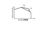
図15は、稼動モードに応じたエンジン回転数とエンジントルクの最大値との関係(最大トルク線)を示す図である。図15において、曲線LPは重掘削モードにおける最大トルク線であり、曲線LEは省燃費モードにおける最大トルク線である。この場合、エンジンの低回転数領域および高回転数領域では、重掘削モードと省燃費モードで同じエンジントルクを得ることができるように設定される一方、エンジンの中間回転数領域では、重掘削モードの方が省燃費モードよりも大きいエンジントルクを得ることができるように設定される。FIG. 15 is a diagram showing a relationship (maximum torque line) between the engine speed and the maximum value of the engine torque according to the operation mode. 15, the curve LP is the maximum torque line in the heavy excavation mode, a curve LE is the maximum torque line in fuel economy mode. In this case, the engine speed is set so that the same engine torque can be obtained in the heavy excavation mode and the fuel saving mode in the low engine speed region and the high engine speed region, while the heavy excavation mode is set in the intermediate engine speed region. Is set so that a larger engine torque can be obtained than in the fuel saving mode.
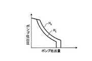
図16は、稼動モードに応じた油圧ポンプのポンプ吐出量とポンプ吐出圧との関係を示す図であり、ポンプ吐出量とポンプ吐出圧との積に比例する油圧ポンプの吸収馬力が一定となる制御を受ける場合の等馬力特性を稼動モードごとに示す図である。図16において、曲線HPは重掘削モードにおける等馬力特性を示す一方、曲線HEは省燃費モードにおける等馬力特性を示している。この場合、ポンプ吐出量が小さい領域を除いて、重掘削モードにおける馬力が省燃費モードにおける馬力よりも大きくなるように設定される。FIG. 16 is a diagram showing the relationship between the pump discharge amount and the pump discharge pressure of the hydraulic pump according to the operation mode, and the absorption horsepower of the hydraulic pump that is proportional to the product of the pump discharge amount and the pump discharge pressure is constant. It is a figure which shows the equal horsepower characteristic in the case of receiving control for every operation mode. 16, the curve HP while indicating equal horsepower characteristics in heavy excavation mode, a curve HE represents the equal horsepower characteristics in fuel economy mode. In this case, except for a region where the pump discharge amount is small, the horsepower in the heavy excavation mode is set to be larger than the horsepower in the fuel saving mode.
稼動モードを設定することが可能な建設機械では、図15および図16に示す特性に基づいて、設定された稼動モードに応じたエンジントルクとポンプ吸収トルクとを選択し、この二つのトルクが一致するマッチング点付近にエンジン回転数を保つような制御が行われる。 In a construction machine that can set the operation mode, the engine torque and the pump absorption torque corresponding to the set operation mode are selected based on the characteristics shown in FIGS. 15 and 16, and the two torques match. Control is performed to keep the engine speed near the matching point.
しかしながら、上述した従来技術では、操作者が稼動モードを任意に設定することができるため、常に管理者が意図する稼動モードが選択されるとは限らなかった。具体的には、例えば川底を掘削したり、砂山の砂を掘削したりするような、建設機械にとって比較的大きなパワーを必要としない作業を行う状況下であって省燃費モードを用いた方が好ましい状況下であっても、操作者の意向によって、より速く作業を行うために重掘削モードが選択されてしまう場合があった。 However, in the above-described prior art, since the operator can arbitrarily set the operation mode, the operation mode intended by the administrator is not always selected. Specifically, it is better to use the fuel saving mode in situations where construction machinery does not require relatively large power, such as excavating the bottom of a river or excavating sand in a sand pile. Even under favorable circumstances, the heavy excavation mode may be selected in order to perform the work faster depending on the intention of the operator.
また、上述した従来技術では、操作者が稼動モードを任意に設定することができるため、例えば市街地で建設機械を稼動したり、夜間に建設機械を稼動したりする場合、建設機械の管理者または作業現場の管理者が、作業機の騒音や走行時の騒音に配慮した適切な対応を取ることが難しかった。 In the above-described prior art, since the operator can arbitrarily set the operation mode, for example, when operating a construction machine in an urban area or operating a construction machine at night, It was difficult for managers at the work site to take appropriate measures in consideration of the noise of the work equipment and noise during traveling.
さらに、上述した従来技術では、建設機械の管理者または作業現場の管理者が、実際に建設機械を操作する操作者の熟練度を考慮して、その操作者が設定することのできる稼動モードを制限することができなかった。 Furthermore, in the above-described prior art, the operation mode that can be set by the operator of the construction machine or the manager of the work site in consideration of the skill level of the operator who actually operates the construction machine. Could not be restricted.
本発明は、上記に鑑みてなされたものであって、建設機械の管理者側が意図する稼動モードで操作者に作業を行わせることができる建設機械の稼動モード制御装置を提供することを目的とする。 The present invention has been made in view of the above, and an object thereof is to provide an operation mode control device for a construction machine that allows an operator to perform work in an operation mode intended by a manager of the construction machine. To do.
上述した課題を解決し、目的を達成するために、本発明に係る建設機械の稼動モード制御装置は、駆動源であるエンジンと、前記エンジンによって駆動されるポンプと、前記ポンプが吐出する圧油によって駆動する作業機とを備え、複数の稼動モードのいずれかを設定する建設機械の稼動モード制御装置であって、前記複数の稼動モードのうち設定可能とされる稼動モードに関する情報が入力される入力部と、前記入力部で入力された稼動モードに関する情報に基づいて、前記複数の稼動モードのうち設定可能な稼動モードを固定する稼動モード固定部と、を備えたことを特徴とする。 In order to solve the above-described problems and achieve the object, an operation mode control device for a construction machine according to the present invention includes an engine as a drive source, a pump driven by the engine, and pressure oil discharged from the pump. A construction machine operation mode control device configured to set one of a plurality of operation modes, wherein information regarding an operation mode that can be set among the plurality of operation modes is input. And an operation mode fixing unit that fixes an operation mode that can be set out of the plurality of operation modes based on information on the operation mode input by the input unit.
また、本発明に係る建設機械の稼動モード制御装置は、上記発明において、前記稼動モード固定部が前記設定可能な稼動モードを固定する際に前記入力部で入力される認証用の許可信号を記憶する記憶部と、前記記憶部が記憶する許可信号に基づいて、前記入力部で入力された許可信号の認証を行う認証部と、を備え、前記稼動モード固定部は、前記認証部が認証した結果、前記入力部で入力された許可信号が正当な許可信号である場合、前記複数の稼動モードのうち設定可能な稼動モードの固定処理を行うことを特徴とする。 The operation mode control device for a construction machine according to the present invention stores an authentication permission signal input at the input unit when the operation mode fixing unit fixes the settable operation mode. And an authentication unit that authenticates the permission signal input at the input unit based on the permission signal stored in the storage unit, and the operation mode fixing unit is authenticated by the authentication unit As a result, when the permission signal input from the input unit is a valid permission signal, a fixed operation mode settable among the plurality of operation modes is performed.
また、本発明に係る建設機械の稼動モード制御装置は、上記発明において、前記稼動モード固定部における稼動モードの固定機能を有効または無効とする稼動モード固定機能設定部を備えたことを特徴とする。 The construction machine operation mode control device according to the present invention is characterized in that, in the above-mentioned invention, an operation mode fixing function setting unit for enabling or disabling the operation mode fixing function in the operation mode fixing unit is provided. .
また、本発明に係る建設機械の稼動モード制御装置は、上記発明において、稼動モードの選択を促す稼動モード選択画面を少なくとも表示する表示部と、前記稼動モード固定部を含み、前記表示部の表示動作を制御する表示制御部と、を備え、前記表示制御部は、前記稼動モード固定部によって前記設定可能な稼動モードが固定された場合において、前記表示部に前記稼動モード選択画面を表示させるとき、前記設定可能な稼動モードの項目のみを選択可能な状態で前記表示部に表示させるとともに、前記設定可能な稼動モードのみを前記入力部によって入力受付可能とすることを特徴とする。 In addition, the construction machine operation mode control apparatus according to the present invention includes, in the above-described invention, a display unit that displays at least an operation mode selection screen that prompts selection of an operation mode, and the operation mode fixing unit. A display control unit that controls operation, and the display control unit displays the operation mode selection screen on the display unit when the settable operation mode is fixed by the operation mode fixing unit. In addition, only the settable operation mode items are displayed on the display unit in a selectable state, and only the settable operation mode can be input by the input unit.
また、本発明に係る建設機械の稼動モード制御装置は、上記発明において、前記表示制御部は、前記表示部に前記許可信号の入力を促す許可信号入力画面を表示させている最中に前記入力部で許可信号が入力され、前記認証部が認証した結果、入力された許可信号が正当な許可信号である場合、前記表示部に前記設定可能な稼動モードの固定を促す稼動モード固定設定画面を表示させることを特徴とする。 In the construction machine operation mode control device according to the present invention, in the above invention, the display control unit displays the permission signal input screen for prompting the input of the permission signal on the display unit. When the permission signal is input by the authentication unit and the authentication unit authenticates, if the input permission signal is a valid permission signal, an operation mode fixing setting screen for prompting the display unit to fix the settable operation mode is displayed. It is characterized by being displayed.
また、本発明に係る建設機械の稼動モード制御装置は、上記発明において、前記記憶部は、前記複数の稼動モードのうち前記設定可能な稼動モードをモード固定用許可信号と対応付けて記憶し、前記稼動モード固定部は、前記入力部で入力されたモード固定用許可信号に応じて前記設定可能な稼動モードを固定することを特徴とする。 In the construction machine operation mode control device according to the present invention, in the above invention, the storage unit stores the set operation mode out of the plurality of operation modes in association with a mode fixing permission signal, The operation mode fixing unit fixes the set operation mode in accordance with a mode fixing permission signal input from the input unit.
本発明によれば、入力部で入力された稼動モードに関する情報に基づいて、複数の稼動モードのうち設定可能な稼動モードを固定する稼動モード固定部を備えているため、管理者側が意図する稼動モードで操作者に作業を行わせることが可能となる。 According to the present invention, since the operation mode fixing unit that fixes a settable operation mode among a plurality of operation modes is provided based on the information related to the operation mode input by the input unit, the operation intended by the administrator side is provided. In this mode, the operator can perform work.
以下、添付図面を参照して本発明を実施するための形態(以下、「実施の形態」という)を説明する。 DESCRIPTION OF EMBODIMENTS Hereinafter, embodiments for carrying out the present invention (hereinafter referred to as “embodiments”) will be described with reference to the accompanying drawings.
(実施の形態1)
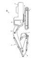
図1は、本発明の実施の形態1に係る建設機械の稼動モード制御装置を搭載した建設機械の簡略図である。同図に示す建設機械101は油圧ショベルであって、履帯等を有する下部走行体1と、下部走行体1の上部に旋回機構2を介して旋回可能に装着される上部旋回体3と、上部旋回体3に取付られている作業機4とを備える。作業機4は、その基部が上部旋回体3に揺動可能に連結されているブーム5と、ブーム5の先端に揺動可能に連結されているアーム6と、アーム6の先端に揺動可能に連結されているバケット7とを備える。また、上部旋回体3は、運転室8等を備える。(Embodiment 1)
FIG. 1 is a simplified diagram of a construction machine equipped with an operation mode control device for a construction machine according to
図2は、運転室8の内部の構成を示す斜視図である。運転室8は、図2に示すように、その中央部に運転席9が設けられ、この運転席9の前方に走行操作部10が設けられている。この走行操作部10は、走行レバー11、12 と、各走行レバー11、12と一体に揺動する走行ペダル13、14とを備える。操作者が走行レバー11、12を前方に押すと下部走行体1が前進する一方、操作者が走行レバー11、12を後方に引くと下部走行体1が後進する。走行操作部10の近傍には、アタッチメント用ペダル15が設けられている。また、図2の右方の側方窓16の近傍には、計器盤17が設けられている。 FIG. 2 is a perspective view showing an internal configuration of the
運転席9の左右側部には、作業機レバー18、19がそれぞれ設置されている。作業機レバー18、19は、ブーム5の上下動、アーム6およびバケット7の回動、ならびに上部旋回体3の旋回操作等を行うものである。さらに、作業機レバー18の近傍にはロックレバー20が設けられている。ここで、ロックレバー20とは、作業機4の操作、上部旋回体3の旋回、および下部走行体1の走行等の機能を停止させるためのものである。すなわち、ロックレバー20の引き上げ操作を行うことによって、作業機4等の動きをロック(規制)することができる。ロックレバー20によって作業機4等の動きがロックされた状態では、操作者が作業機レバー18、19等を操作しても、作業機4等が動作しない。 Work machine levers 18 and 19 are installed on the left and right sides of the driver's
運転室8の前方窓22と一方の側方窓16とを仕切る縦枠23の下部には、建設機械101のエンジン状態等を表示するモニタ装置21が設けられている。ここで、エンジン状態等とは、例えば、エンジン冷却水の温度、作動油温度、燃料残量等である。 A
図3は、建設機械101の制御システムの構成を示す簡略図である。図3に示すように、建設機械101の制御システムは、作業機4等を駆動する油圧を発生させるための圧油を吐出する第1油圧ポンプ31aと、作業機レバー18、19の操作に応じた油圧を発生させるための圧油を吐出する第2油圧ポンプ31bとを有している。第1油圧ポンプ31aには、斜板駆動装置32が接続されている。斜板駆動装置32は、ポンプコントローラ33からの指示に基づいて駆動し、第1油圧ポンプ31aの斜板の傾斜角度を変更する。第1油圧ポンプ31a には、コントロールバルブ34を介して油圧アクチュエータ35が接続される。油圧アクチュエータ35は、ブーム用シリンダ、アーム用シリンダ、バケット用シリンダ、旋回用油圧モータ、および走行用油圧モータ等である。また、第2油圧ポンプ31bには、作業機レバー18(19)とロックレバー20とが接続されている。 FIG. 3 is a simplified diagram showing the configuration of the control system of the
また、建設機械101の制御システムは、第1油圧ポンプ31aおよび第2油圧ポンプ31bと接続する駆動軸を有するエンジン36と、エンジン36内の燃料噴射装置による燃料噴射量を調節するためのガバナモータ37と、エンジン36の動作を制御するエンジンコントローラ38とを備える。エンジン36はディーゼルエンジンである。エンジン36のエンジン回転数は、燃料ダイヤル39によってセットされ、実際のエンジン回転数は回転センサ40によって検出される。エンジンコントローラ38は、操作者によるレバー操作信号、作業機4など設けられた各種センサのセンサ信号等に基づいて、燃料噴射装置が噴射する燃料量等の制御を行う。ポンプコントローラ33は、稼動モードごとに設定されたポンプ吸収トルク、燃料ダイヤル39でセットされたエンジン回転数、および実際のエンジン回転数に応じて、第1油圧ポンプ31aがエンジン36の各出力点でのベストマッチングのトルクを吸収するような制御を行う。ポンプコントローラ33およびエンジンコントローラ38は、建設機械101のコントローラ41を構成する。 The control system for the
ここで、建設機械101の稼動モードとして、大きな作業量を維持できる重掘削モードと、燃料消費を抑えつつ、軽負荷作業では重掘削モード並みの作業機スピードを実現可能な省燃費モードとを設定することが可能な場合を説明する。この場合、エンジン36の低回転数領域および高回転数領域では、重掘削モードと省燃費モードで同じエンジントルクを得ることができるように設定される一方、エンジン36の中間回転数領域では、重掘削モードの方が省燃費モードよりも大きいエンジントルクを得ることができるように設定される(図15を参照)。また、建設機械101の稼動モードとして、重掘削モードと省燃費モードとを設定することが可能な場合、第1油圧ポンプ31aの吸収馬力が一定となるような制御を受ける際の等馬力特性は、ポンプ吐出量が小さい領域を除いて、重掘削モードにおける馬力が省燃費モードにおける馬力よりも大きくなるように設定される(図16を参照)。 Here, as an operation mode of the
引き続き、建設機械101の制御システムの構成を説明する。ロックレバー20には、PPCロックスイッチ42が接続されている。PPCロックスイッチ42は、ロックレバー20がロック側へ操作されたときにその操作を検知し、バルブ(ソレノイドバルブ)43へ信号を送る。これによって、作業機4の操作、上部旋回体3の旋回、および下部走行体1の走行等の機能を停止させることができる。この際、エンジン36はアイドル回転数となってアイドリング状態となる。 Next, the configuration of the control system of the
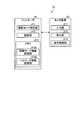
図4は、建設機械101の制御システムの一部をなす稼動モード制御装置の機能構成を示すブロック図である。図4に示すように、建設機械101の稼動モード制御装置51は、コントローラ41と、モニタ装置21とを備える。 FIG. 4 is a block diagram illustrating a functional configuration of an operation mode control device that forms a part of the control system of the
コントローラ41は、建設機械101で設定可能な稼動モードを固定する稼動モード固定部411と、モニタ装置21を介して稼動モードを固定する際に入力される許可信号であるパスワードの認証を行う認証部412と、メモリ413とを有する。メモリ413は、稼動モードに関する情報を記憶する稼動モード情報記憶部413aと、認証部412がパスワードの認証を行う際に参照するパスワードの情報を記憶するパスワード情報記憶部413bとを有する。コントローラ41は、CPU、EEPROM等が用いられる。 The
次に、モニタ装置21の構成を説明する。モニタ装置21は、図4に示すように、各種情報の入力を受け付ける入力部211と、液晶画面等を用いて実現され、建設機械101の動作に関する情報を含む各種情報を表示する表示部212と、モニタ装置21の内部に設けられ、コントローラ41と信号の送受信が可能であり、モニタ装置21の動作を制御するCPU等からなる表示制御部213とを有する。 Next, the configuration of the
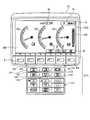
図5は、モニタ装置21の外観構成を示す図である。入力部211は、複数のスイッチによって構成されている。入力部211のうち、表示部212の下方に位置し、「F1」〜「F6」とそれぞれ表示されているファンクションスイッチF1〜F6は、各スイッチの上方で表示部212が表示するアイコン(例えば図5のアイコンI1〜I3)に対応した信号を入力するためのスイッチである。ファンクションスイッチF1〜F6の下方には、作業機レバー18、19が中立位置に戻った際にエンジン36のエンジン回転数を所定の回転数まで低下させるオートデセル制御を実行させるオートデセルスイッチ111、建設機械101の稼動モードを複数の稼動モードから選択する稼動モード選択スイッチ112、建設機械101の走行速度段を複数の走行速度段から選択する走行速度段選択スイッチ113、建設機械101が所定の警告状態になると発生するブザー音をキャンセルするブザーキャンセルスイッチ114、建設機械101の運転室8(図2を参照)のフロントガラスに設けられるワイパ(図示せず)を動作させるワイパスイッチ115、フロントガラスへ洗浄水を噴射するウォッシャ(図示せず)を作動するウォッシャスイッチ116、および運転室8内のエアコンの各種機能を操作するエアコンスイッチ117を有する。なお、入力部211として、抵抗膜方式等のタッチパネルを適用することも可能である。 FIG. 5 is a diagram showing an external configuration of the
図5において、表示部212が表示している画面は、建設機械101が通常動作中に表示する標準画面301である。標準画面301には、エンジン水温ゲージG1、作動油温ゲージG2および燃料レベルゲージG3が並べて表示されており、それぞれに対応するセンサ信号に基いてゲージの針がふれる。また、燃料レベルゲージG3の右側には、燃料消費ゲージG4が表示されている。表示部212の上方の中央部には時計Wが表示されている。時計Wの右側には、設定されている稼動モードを示す稼動モードアイコンIM、および設定されている走行速度段を示す走行速度段アイコンISが表示されている。In FIG. 5, the screen displayed by the
標準画面301では、稼動モードアイコンIMとして文字「P」が表示されている。これは、稼動モードが重掘削モードに設定されている場合の表示である。これに対して、建設機械101が省燃費モードに設定されている場合、稼動モードアイコンI-Mとして文字「E」が表示される。In the
また、標準画面301では、走行速度段アイコンISとして「Hi」という文字列を含むアイコンが表示されている。このアイコンは、走行速度段が高速に設定されている場合の表示である。走行速度段選択スイッチ113を介して表示制御部213に選択入力される走行速度段は、低速、中速、高速の3種類である。このうち、低速が選択された場合には、走行速度段アイコンISとして文字列「Lo」を含むアイコンが表示される。また、中速が選択された場合には、走行速度段アイコンISとして文字列「Mi」を含むアイコンが表示される。Further, the
標準画面301の下方の位置であってファンクションスイッチF4〜F6の上方の位置には、ファンクションスイッチF4〜F6にそれぞれ対応するガイダンスアイコンI1〜I3が表示されている。このうち、ガイダンスアイコンI1は、表示部212が表示する画面をカメラ画面へ切り換えることを意味するアイコンである。カメラ画面とは、建設機械101の外装部に設置され、建設機械101の外界を撮影するCCDカメラ等のカメラ(図示せず)が出力する画面である。また、ガイダンスアイコンI2は、時計Wの表示をサービスメータの表示へ切り換えることを意味するアイコンである。また、ガイダンスアイコンI3は、表示部212が表示する画面をユーザモード画面へ切り換えることを意味するアイコンである。したがって、例えばガイダンスアイコンI1に対応するファンクションスイッチF4が押されて表示制御部213に信号が入力されると、表示制御部213は、表示部212が表示している画面を切り換えてカメラ画面を表示させる制御を行う。 Guidance icons I1 to I3 corresponding to the function switches F4 to F6 are displayed at positions below the
次に、稼動モード制御装置51に特徴的な処理である稼動モード固定処理の概要を説明する。図6および図7は、表示部212が標準画面301を表示中に操作者によって稼動モード選択スイッチ112が押された場合に、表示部212が表示する稼動モード選択画面の表示例を示す図である。このうち、図6は、稼動モード固定処理が行われていない場合の稼動モード選択画面の表示例である。また、図7は、稼動モード固定処理が行われた場合の稼動モード選択画面の表示例である。 Next, an outline of the operation mode fixing process, which is a process characteristic of the operation
図6に示す稼動モード選択画面311と図7に示す稼動モード選択画面312とを比較すると、稼動モード選択画面312では、「重掘削モード(P)」という項目が薄く破線で表示されており、重掘削モードが選択不可能な状態を表している。このような表示が行われるのは、稼動モード固定部411により、設定可能な稼動モードが省燃費モードのみに固定される処理が行われたためである。このように、稼動モード固定部411が稼動モード固定処理を行った場合、コントローラ41は、表示制御部213を介して、固定された稼動モードのみを表示部212に選択可能な状態で表示(図中実線で表示)させるとともに、固定された稼動モードのみを入力部211によって入力受付可能とする制御を行う。ここでいう「受付」とは、入力部211を介した稼動モードの選択の受付を意味する。 When the operation
ここで、稼動モード選択画面311、312に共通する表示内容を説明する。稼動モード選択画面311、312の下方には、4つのアイコンが表示されている。4つのアイコンは、左から順に、カーソルダウンアイコンId、カーソルアップアイコンIu、画面戻りアイコンIbおよび確定アイコンIcである。Here, display contents common to the operation mode selection screens 311 and 312 will be described. Four icons are displayed below the operation mode selection screens 311 and 312. The four icons are a cursor down icon Id , a cursor up icon Iu , a screen return icon Ib, and a confirmation icon Ic in order from the left.
カーソルダウンアイコンIdの下方に位置するファンクションスイッチF3が押されて表示制御部213に信号が入力されると、表示制御部213は、その時点で選択状態にある稼動モードの項目の一つ下に表示されている稼動モードの項目を選択状態として表示させる一方、現在選択状態にある稼動モードの項目を未選択状態として表示させる。例えば、図6に示す状態でファンクションスイッチF3が押されて表示制御部213に信号が入力されると、その時点で選択状態(図では網掛け表示)にある項目「重掘削モード(P)」の一つ下に表示されている項目「省燃費モード(E)」が選択状態として表示され、項目「重掘削モード(P)」の方が未選択状態として表示(網掛けなしで表示)される。なお、図7では、省燃費モード以外を選択することができないため、操作者がファンクションスイッチF3あるいはF4を押しても稼動モードの選択状態は変わらない。When the signal to the
カーソルアップアイコンIuの下方に位置するファンクションスイッチF4が表示制御部213に押されて信号が入力されると、表示制御部213は、現在選択状態にある稼動モードの一つ上に表示されている稼動モードを選択状態として表示させる一方、現在選択状態にある稼動モードを未選択状態として表示させる。例えば、図6に示す状態でファンクションスイッチF4が押されて表示制御部213に信号が入力されると、項目「重掘削モード(P)」の一つ上には稼動モードの表示がないため、項目「重掘削モード(P)」の一つ下に表示されている項目「省燃費モード(E)」が選択状態として表示され、項目「重掘削モード(P)」の方が未選択状態として表示される。なお、図7では、省燃費モード以外を選択することができないため、操作者がファンクションスイッチF3あるいはF4を押しても稼動モードの選択状態は変わらない。When the function switch F4 located below the cursor up icon Iu is pushed signal to the
画面戻りアイコンIbの下方に位置するファンクションスイッチF5が押されて表示制御部213に信号が入力されると、表示制御部213は、表示部212で表示する画面を一つ前に表示していた画面に戻す。When the screen returns icon Ib of the signal to the
確定アイコンIcの下方に位置するファンクションスイッチF6が押されて信号が表示制御部213に入力されると、表示制御部213を介してその信号を受信したコントローラ41は、選択状態にある稼動モードに対して選択を確定したと認識し、選択内容に応じた後続の処理へ移行する。図6に示す稼動モード選択画面311では、項目「重掘削モード(P)」が選択状態にあるため、この状態でファンクションスイッチF6が押されると、コントローラ41は重掘削モードに対応した処理を行う。これに対し、図7に示す稼動モード選択画面312では、項目「省燃費モード(E)」が選択状態にあるため、この状態でファンクションスイッチF6が押されると、コントローラ41は省燃費モードに対応した処理を行う。The enter icon I function switch F6 is depressed the signal located below thec is input to the
このように、本実施の形態1においては、稼動モード制御装置51が稼動モード固定処理を行う機能を備えているため、操作者が設定可能な稼動モードにあらかじめ制限を加えておくことができる。この結果、稼動モードが固定された建設機械101に対し、操作者がエンジンキーをオンして操作を開始すると、操作者は、制限された範囲内でしか稼動モードの選択を行うことができない。 As described above, in the first embodiment, since the operation
なお、選択不可能な状態にある稼動モードの表示方法は、図7に示すような破線による表示に限られるわけではない。例えば、選択可能な状態にある稼動モードと選択不可能な状態にある稼動モードとを異なる色で表示するようにしてもよいし、選択不可能な状態にある稼動モードを表示部212で表示しないようにしてもよい。 In addition, the display method of the operation mode in the state which cannot be selected is not restricted to the display by a broken line as shown in FIG. For example, the operation mode in a selectable state and the operation mode in a non-selectable state may be displayed in different colors, or the operation mode in a non-selectable state is not displayed on the
以下、稼動モード制御装置51における稼動モード固定処理の手順について説明する。図8は、モニタ装置21が稼動モードの固定処理を行う場合の表示部212における画面遷移の例を示す図である。以下に説明する稼動モードの固定処理は、例えば建設機械101の管理者や建設機械101の作業現場の管理者によって行われる。なお、建設機械101の操作者自身が稼動モードの固定処理を行うことを妨げるものではないが、その場合は、後述するパスワードを操作者が知っている必要がある。 Hereinafter, the procedure of the operation mode fixing process in the operation
まず、運転室8に設けられた図示しないキースイッチをオンすると、エンジン36が起動するとともに、表示部212が標準画面301を表示する。 First, when a key switch (not shown) provided in the
標準画面301で「設定画面」への遷移を意図するガイダンスアイコンI3に対応するファンクションスイッチF6が押されて信号が表示制御部213に入力されると(S1)、表示制御部213は表示部212における表示を標準画面301から設定画面302へ切換える。なお、標準画面301から設定画面302へ遷移する際にパスワードの入力を必要とする構成にしてもよい。 When the function switch F6 corresponding to the guidance icon I3 intended to transition to the “setting screen” is pressed on the
図8に示す場合、設定画面302では、「稼動モード固定設定」という項目を含む3つの設定項目が表示されるとともに、画面の下部にカーソルダウンアイコンId、カーソルアップアイコンIu、画面戻りアイコンIbおよび確定アイコンIcが表示されており、項目「稼動モード固定設定」が選択された状態(網掛けで表示)になっている。この状態で確定アイコンIcに対応するファンクションスイッチF6が押されて表示制御部213に信号が入力されると(S2)、表示制御部213は表示部212にパスワード入力画面303を表示させる。In the case shown in FIG. 8, on the
パスワードは、複数桁の数字を入力部211の各スイッチに割り振られた数字を押すことによって入力することができる。表示部212がパスワード入力画面303を表示した状態で、オートデセルスイッチ111は、そのスイッチの右下部に表示された数字1に相当する信号の入力を受け付ける。同様に、表示部212がパスワード入力画面303を表示した状態で、稼動モード選択スイッチ112、走行速度段選択スイッチ113、ブザーキャンセルスイッチ114、ワイパスイッチ115、ウォッシャスイッチ116は、数字2,3,4,5,6にそれぞれ相当する信号の入力を受け付ける。また、エアコンスイッチ117に含まれるスイッチの中には、パスワード入力画面303が表示された状態で、数字7,8,9,0にそれぞれ相当する信号の入力を受け付けるスイッチがある。例えば、エアコンスイッチ117のうち「AUTO」と表示されたスイッチは、表示部212がパスワード入力画面303を表示した状態で、数字9の入力を受け付ける。なお、パスワードは英文字や記号または数字とそれらの組み合わせであってもよい。 The password can be input by pressing a number of multiple digits assigned to each switch of the
表示部212がパスワード入力画面303を表示した状態で入力部211が許可信号であるパスワードの入力を受け付けた後、ファンクションスイッチF6が押されて表示制御部213に信号が入力されると、表示制御部213を介してその信号を受信した認証部412は、パスワード情報記憶部413bがあらかじめ記憶しているパスワードを参照してパスワードの認証(照合判断)を行う。認証部412が認証した結果、入力部211によって入力されたパスワードがパスワード情報記憶部413bから読み出したパスワードと一致している場合、認証部412は、表示制御部213に対してパスワードが正当であることを示す認証結果を送信する。この認証結果を受信した表示制御部213は、図8に示すように、表示部212に稼動モードの固定を促す稼動モード固定設定画面304を表示させる(S3)。なお、認証部412が認証した結果、入力部211によって入力されたパスワードがパスワード情報記憶部413bから読み出したパスワードと一致しない場合、その認証結果を受信した表示制御部213は、表示部212にパスワードの再入力を促すメッセージを表示させる。 When the
稼動モード固定設定画面304では、固定対象となる稼動モードの項目が表示されるとともに、全ての稼動モードを固定しない場合に対応する項目「なし」が表示されており、項目「省燃費モード(E)」が選択された状態(網掛けで表示)となっている。また、稼動モード固定設定画面304では、カーソルダウンアイコンId、カーソルアップアイコンIu、画面戻りアイコンIbおよび確定アイコンIcが表示される。この表示状態でファンクションスイッチF6が押されて表示制御部213に信号が入力されると(S4)、表示制御部213を介してその信号を受信した稼動モード固定部411は、選択された稼動モードの固定処理を行い、固定した稼動モードを識別する情報を稼動モード情報記憶部413aに書き込んで記憶させる。より具体的には、稼動モード固定部411は、稼動モード情報記憶部413aで記憶する稼動モードのうち、稼動モード固定設定画面で選択された稼動モードに固定フラグを立てる処理を行う。On the operation mode fixed
その後、表示制御部213は、表示部212に設定画面302を再び表示させる。 Thereafter, the
以上により、稼動モード固定処理が完了する。なお、図8において、設定画面302、パスワード入力画面303および稼動モード固定設定画面304をそれぞれ表示している状態で、画面戻りアイコンIbに対応するファンクションスイッチF5が押された場合、表示制御部213は、その時点で表示している画面へ遷移する前に表示していた画面を表示部212に再表示させる。例えば、表示制御部213は、図8の設定画面302が表示されている状態でファンクションスイッチF5が押されると、標準画面301を表示部212に表示させる制御を行う。なお、表示部212が稼動モード固定設定画面304を表示している状態でファンクションスイッチF6が押されて設定画面302に遷移(S4)した後、表示部212が設定画面302を表示している状態でファンクションスイッチF5が押されたとき、表示制御部213は、表示部212に標準画面301を表示させる制御を行う。Thus, the operation mode fixing process is completed. In FIG. 8, the
図9は、稼動モード固定の有無に応じた稼動モード選択時の画面遷移例を示す図である。表示部212が標準画面301を表示している状態で稼動モード選択スイッチ112が押されて表示制御部213に信号が入力されると、表示制御部213は表示部212に稼動モード選択画面311または312を表示させる。 FIG. 9 is a diagram illustrating an example of screen transition when an operation mode is selected depending on whether or not the operation mode is fixed. When the operation
具体的には、コントローラ41は、稼動モード情報記憶部413aが記憶する稼動モードの情報を参照し、稼動モードに固定フラグが立っているか否かを判定し、その判定結果を表示制御部213へ送信する。コントローラ41が判定した結果、全ての稼動モードに固定フラグが立っていない場合(S11)、その判定結果を受信した表示制御部213は、設定可能な稼動モードを全て表示する稼動モード選択画面311を表示させる。図9に示す稼動モード選択画面311では、項目「省燃費モード(E)」が選択可能な状態となっている。 Specifically, the
これに対し、コントローラ41が判定した結果、固定フラグが立っている稼動モードが存在している場合(S12)、その判定結果を受信した表示制御部213は、表示部212に固定フラグが立っている稼動モードの項目のみを選択可能な状態とした稼動モード選択画面312を表示させる。 On the other hand, as a result of the determination by the
稼動モード選択画面311または312で稼動モードが選択され、ファンクションスイッチF6が押されて信号が入力された場合(S13、S14)、表示制御部213は表示部212に標準画面301を再表示させる。図9に示す場合、稼動モード選択画面311、312では省燃費モードが選択されているため、標準画面301では、稼動モードアイコンIMとして文字「E」が表示される。When the operation mode is selected on the operation
なお、本実施の形態1では、稼動モードとして、建設機械101の走行速度を低速または高速に切り換える走行モード(走行速度段選択)についても、稼動モード固定部411によって管理者が意図するモードに固定することができる。例えば、管理者が低速モードのみに固定した場合、コントローラ41は、油圧アクチュエータ35に含まれる油圧走行モータへの油の流量を制限し、低速モードでしか稼動しないような制御を行う。このようにして、走行モードのモード固定が行われると、操作者は、モニタ装置21の走行速度段選択スイッチ113によって走行モードを変更しようとしても、稼動モード固定部411によってあらかじめ固定された走行モードしか選択することができない。したがって、例えば走行モードを低速モードに固定することにより、市街地で走行したり夜間に走行したりする場合、騒音に配慮した建設機械101の走行を実現させることができる。 In the first embodiment, as the operation mode, the operation
以上説明した本発明の実施の形態1によれば、入力部で入力された稼動モードに関する情報に基づいて、複数の稼動モードのうち設定可能な稼動モードを固定する稼動モード固定部を備えているため、管理者側が意図する稼動モードで操作者に作業を行わせることが可能となる。 According to
また、本実施の形態1によれば、稼動モード選択画面において、複数の稼動モードを表示するものの固定された稼動モードの項目のみを選択可能な状態として強調して表示し、固定された稼動モードのみを入力受付可能とするため、操作者は稼動モードの選択を任意に行うことができない。したがって、操作者による稼動モードの選択に制限を設け、作業の種類に応じた適切な稼動モードで建設機械を動作させることが可能となる。 Further, according to the first embodiment, on the operation mode selection screen, although a plurality of operation modes are displayed, only the items of the fixed operation mode are highlighted and displayed as selectable states, and the fixed operation mode is displayed. Therefore, the operator cannot arbitrarily select the operation mode. Therefore, it is possible to limit the selection of the operation mode by the operator and operate the construction machine in an appropriate operation mode according to the type of work.
また、本実施の形態1によれば、建設機械をレンタルするレンタル会社の管理者や作業現場の管理者が、ユーザの作業内容や作業現場の状況に応じて選択可能な稼動モードを固定して制限することにより、管理者の意図を反映して、操作者は作業現場の環境や操作者の熟練度などに応じて建設機械の作業を行うことが可能となる。 In addition, according to the first embodiment, the manager of the rental company that rents the construction machine or the manager of the work site fixes the operation mode that can be selected according to the user's work content or the situation of the work site. By limiting, the operator's intention is reflected, and the operator can work on the construction machine according to the environment at the work site, the skill level of the operator, and the like.
(実施の形態2)
図10は、本発明の実施の形態2に係る建設機械の稼動モード制御装置の機能構成を示すブロック図である。同図に示す稼動モード制御装置61は、上述した実施の形態1に係る稼動モード制御装置51とコントローラの構成が異なる。具体的には、稼動モード制御装置61のコントローラ62は、稼動モード固定部411、認証部412に加えて、稼動モード固定部411が具備する稼動モード固定機能を有効または無効とする稼動モード固定機能設定部611を有する。このように、コントローラ62が稼動モード固定機能設定部611を有しているため、稼動モード制御装置61では、稼動モード固定機能自体を使用するか否かを設定することができる。したがって、稼動モード固定機能を使用しないという選択がなされた場合、操作者は従来どおりの使用方法によって建設機械101を操作することができる。(Embodiment 2)
FIG. 10 is a block diagram showing a functional configuration of an operation mode control device for a construction machine according to
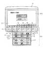
図11は、稼動モード制御装置61が稼動モードの固定機能を有効または無効とする処理を行う場合の表示部212における画面遷移の例を示す図である。図12は、表示部212における標準画面の表示例を示す図である。本実施の形態2において、表示部212が表示する標準画面321では、図5を参照して説明した標準画面301と同じ内容に加えて、文字列「パスワード」を表示するガイダンスアイコンI4がさらに表示される。このガイダンスアイコンI4は、図12に示すように、その下方に位置するファンクションスイッチF3に対応している。 FIG. 11 is a diagram illustrating an example of screen transition in the
図11において、表示部212が標準画面321を表示している状態でファンクションスイッチF6が押されて表示制御部213に信号が入力されると(S21)、表示制御部213は、表示部212にパスワード入力画面322を表示させる。ここで、パスワードを表示するガイダンスアイコンI4を表示せずに、入力部211の任意のスイッチ操作によってパスワード入力画面322を表示させることも可能である。パスワードは、複数桁の数字を入力部211の各スイッチに割り振られた数字を押すことによって入力することができる。なお、パスワードは英文字や記号或いは数字とそれらの組み合わせであってもよい。 In FIG. 11, when the function switch F <b> 6 is pressed and a signal is input to the
表示部212がパスワード入力画面322を表示した状態で入力部211がパスワードの入力を受け付けた後、ファンクションスイッチF6が押され、このファンクションスイッチF6に対応する信号が、表示制御部213を介して認証部412に入力されると(S22)、認証部412は、パスワード情報記憶部413bが記憶しているパスワードを参照してパスワードの認証(照合判断)を行う。認証部412が認証した結果、入力部211によって入力されたパスワードがパスワード情報記憶部413bから読み出したパスワードと一致している場合、認証部412は、表示制御部213に対してパスワードが正当であることを示す認証結果を送信する。この認証結果を受信した表示制御部213は、図11に示すように、表示部212に稼動モードの固定機能の使用/未使用の選択入力を促す稼動モード固定機能使用/未使用選択画面323を表示させる。パスワード入力画面322の表示中に入力されるべきパスワードは、パスワード入力画面303(図8を参照)において入力されるべきパスワードと同じでよい。なお、認証部412が認証した結果、入力部211によって入力されたパスワードがパスワード情報記憶部413bから読み出したパスワードと一致しない場合、認証部412からこの判定結果を受信した表示制御部213は、表示部212にパスワードの再入力を促すメッセージを表示させる。 After the
稼動モード固定機能使用/未使用選択画面323では、図11に示すように、「稼動モード固定機能を使用しますか?」という文字列が表示されるとともに、二つの項目「使用する」および「使用しない」が表示される。また、稼動モード固定機能使用/未使用選択画面323では、画面の下方にカーソルダウンアイコンId、カーソルアップアイコンIu、画面戻りアイコンIbおよび確定アイコンIcが並べて表示される。カーソルダウンアイコンId、カーソルアップアイコンIu、画面戻りアイコンIbおよび確定アイコンIcは、図6に示す稼動モード選択画面311と同様、ファンクションスイッチF3〜F6に順次対応している。In the operation mode fixing function use /
表示部212が稼動モード固定機能使用/未使用選択画面323を表示している最中に項目「使用する」および「使用しない」のいずれか一方を選択する信号が入力部211によって表示制御部213に入力されると、表示制御部213は表示部212に標準画面324を表示させる。 While the
稼動モード固定機能使用/未使用選択画面323で項目「使用する」が選択され、ファンクションスイッチF6が押されて信号が入力された場合(S23)、すなわち稼動モード固定機能を有効とする選択がなされた場合、表示制御部213を介して項目「使用する」に対応する信号を受信した稼動モード固定機能設定部611は、稼動モード固定機能を有効とする設定を行い、稼動モード固定機能が有効化されたことを通知する信号を表示制御部213へ送信する。表示制御部213から稼動モード固定機能が有効化されたことを通知する信号を受信した表示制御部213は、表示部212に稼動モードアイコンIMを網掛け表示した状態で標準画面324を表示させる(図11を参照)。これにより、操作者は、標準画面324上で稼動モード固定機能が有効になっていることを認識することができる。なお、稼動モード固定機能が有効であることを表示する形態は、稼動モードアイコンIuを網掛け表示する形態に限られるわけではなく、文字表示する形態を採用することも可能である。When the item “use” is selected on the operation mode fixing function use /
その後、標準画面324でガイダンスアイコンI3に対応するファンクションスイッチF6が押されて表示制御部213に信号が入力されると、表示制御部213は、表示部212に設定画面302(図8を参照)を表示させる。 Thereafter, when the function switch F6 corresponding to the guidance icon I3 is pressed on the
一方、稼動モード固定機能使用/未使用選択画面323で項目「使用しない」が選択され、ファンクションスイッチF6が押されて信号が入力された場合、すなわち稼動モード固定機能を無効とする選択がなされた場合、表示制御部213を介して項目「使用しない」に対応する信号を受信した稼動モード固定機能設定部611は、稼動モード固定機能を無効とする設定を行い、稼動モード固定機能が無効化されたことを通知する信号を表示制御部213へ送信する。表示制御部213から稼動モード固定機能が無効化されたことを通知する信号を受信した表示制御部213は、表示部212にもとの標準画面321を再表示させる。 On the other hand, when the item “not used” is selected on the operation mode fixed function use /
図13は、稼動モード固定機能設定部611が稼動モード固定機能を無効とした場合において、標準画面321で表示されるガイダンスアイコンI3に対応するファンクションスイッチF6が押されて信号が入力されたとき、表示部212が表示する設定画面の表示例を示す図である。同図に示す設定画面325は、項目「稼動モード固定設定」が選択不可能な状態を表している(図13では破線で表示)。また、「稼動モード固定設定」の表示そのものを非表示とすることにより、稼動モード固定機能が無効であることを示すこともできる。 FIG. 13 shows a case where the function switch F6 corresponding to the guidance icon I3 displayed on the
以上説明した本発明の実施の形態2によれば、実施の形態1と同様、建設機械の管理者側が意図する稼動モードで操作者に作業を行わせることができる。 According to the second embodiment of the present invention described above, as in the first embodiment, the operator can perform work in the operation mode intended by the manager of the construction machine.
また、本実施の形態2によれば、稼動モード固定機能自体を有効または無効にすることができるため、稼動モード固定機能を有効とした場合には管理者が所望する稼動モードで建設機械を作動させることができる一方、稼動モード固定機能を無効とした場合には操作者が従来どおりの使用方法を確保することができる。したがって、多様な形態で建設機械を動作させることが可能となる。 Further, according to the second embodiment, since the operation mode fixing function itself can be enabled or disabled, when the operation mode fixing function is enabled, the construction machine is operated in the operation mode desired by the administrator. On the other hand, when the operation mode fixing function is disabled, the operator can ensure the conventional usage. Therefore, the construction machine can be operated in various forms.
ここまで、本発明を実施するのに好適な形態を説明してきたが、本発明は上述した二つの実施の形態によってのみ限定されるべきではない。例えば、モニタ装置21において稼動モード固定設定画面304を表示する代わりに、モード固定用パスワード(モード固定用許可信号の例)を入力することによって設定可能な稼動モードの固定処理を行うようにしてもよい。図14は、メモリ413が記憶するモード固定用パスワードと設定可能な稼動モードとの対応を示す図である。この場合、例えば「AAA」というモード固定用パスワードが入力されたとき、稼動モード固定部411は、メモリ413があらかじめ記憶している情報であるテーブルTbをメモリ413から読み出して参照することにより、重掘削モードへのモード固定を行う。また、「BBB」というモード固定用パスワードが入力された場合、稼動モード固定部411は省燃費モードへのモード固定を行う。また、「ZZZ」というモード固定用パスワードが入力された場合、稼動モード固定部411は、全ての稼動モードを選択可能とする。 Up to this point, preferred embodiments for carrying out the present invention have been described, but the present invention should not be limited only by the two embodiments described above. For example, instead of displaying the operation mode fixing
また、本発明は、モニタ装置が表示する各種画面を介さずにモード固定を行ったり、モード固定機能の有効化または無効化を行ったりすることもできる。例えば、図5に示すモニタ装置21の入力部211の操作スイッチのうち、管理者のみが知っている組み合わせからなる複数のスイッチを同時に押すことにより、表示制御部213を介して稼動モード固定部411(図4、10を参照)に稼動モード固定を指示する信号を許可信号として入力したり、稼動モード固定機能設定部611(図10を参照)に稼動モード固定機能の有効化または無効化を指示する信号を許可信号として入力したりするようにしてもよい。 Further, according to the present invention, the mode can be fixed without using various screens displayed by the monitor device, and the mode fixing function can be validated or invalidated. For example, among the operation switches of the
また、モニタ装置21の入力部211の操作スイッチのうち、所定の複数のスイッチを、管理者のみが知っている順序で押すことにより、表示制御部213を介して稼動モード固定部411に稼動モード固定を指示する信号を許可信号として入力したり、稼動モード固定機能設定部611に稼動モード固定機能の有効化または無効化を指示する信号を許可信号として入力したりするようにしてもよい。 In addition, by pressing a plurality of predetermined switches among the operation switches of the
さらに、図2に示す運転室8の計器盤17に設けられた各種スイッチを、稼動モードに関する情報を入力する入力部として用いることにより、稼動モード固定部411に稼動モード固定を指示する信号を許可信号として入力したり、稼動モード固定機能設定部611に稼動モード固定機能の有効化または無効化を指示する信号を許可信号として入力したりするようにしてもよい。 Further, by using various switches provided on the
また、管理者用のキー(IDキー)をキーシリンダに差し込んだ場合にのみ、稼動モード固定部411による稼動モード固定処理や、稼動モード固定機能設定部611による稼動モード固定機能の有効化または無効化処理が実行されるようにしてもよい。 Also, only when the administrator key (ID key) is inserted into the key cylinder, the operation mode fixing process by the operation
以上説明したように、モニタ装置21の表示内容とは無関係に稼動モード固定や稼動モード固定機能の有効化または無効化を行う場合には、その入力自体が許可信号の入力に相当する。したがって、この場合には、パスワードをさらに入力する必要はない。 As described above, when the operation mode is fixed or the operation mode fixing function is validated or invalidated regardless of the display content of the
なお、操作者が稼動モードを設定する際にパスワードを入力するような構成とすることもできる。この場合、建設機械の管理者は操作者に対して予めパスワードを教えておく。操作者は、建設機械を作動して稼動モードを選択する際、管理者から教えられたパスワードを入力する。この際のパスワードと稼動モードの対応をテーブルTbで与えることができる。例えば、操作者が管理者から「BBB」というパスワードを教えてもらった場合、このパスワードを入力すると、認証部412による認証を経て、稼動モード固定部411がテーブルTbをメモリ413から読み出して参照することにより、入力されたパスワードに対応した設定可能な稼動モードである省燃費モードを選択して固定する。このようにして、管理者が意図するパスワードを用いて操作者が稼動モードを固定するようにしても、上述した実施の形態と同様の効果を得ることができる。 It is also possible to adopt a configuration in which the operator inputs a password when setting the operation mode. In this case, the manager of the construction machine gives the password to the operator in advance. When the operator operates the construction machine and selects the operation mode, the operator inputs the password taught by the administrator. The correspondence between the password and the operation mode at this time can be given by the table Tb. For example, when the operator has given the password “BBB” from the administrator, when this password is input, the operation
また、以上の説明では、稼動モードとして重掘削モード、省燃費モード、走行モードを設定する場合を説明してきたが、稼動モードはこれらのモードに限られるわけではない。例えば、上り坂でパワーが必要な時にエンジンの出力をアップする走行パワーアップモード、タイヤのスリップを抑制するスリップモード、整地、整正等の作業時に用いる整正モードや、微操作が必要な作業時に用いる微操作モード、エンジン音を抑えた低騒音モードなどをさらに選択することができるようにしてもよい。 In the above description, the case where the heavy excavation mode, the fuel saving mode, and the travel mode are set as the operation mode has been described, but the operation mode is not limited to these modes. For example, traveling power-up mode that increases engine output when power is needed on an uphill, slip mode that suppresses tire slip, leveling mode used during leveling, leveling, and other operations that require fine manipulation It may be possible to further select a fine operation mode used sometimes, a low noise mode in which engine noise is suppressed, and the like.
また、本発明は、ブルドーザやホイールローダ等の建設機械にも適用することが可能である。 The present invention can also be applied to construction machines such as bulldozers and wheel loaders.
このように、本発明は、上述した実施の形態以外にも様々な実施の形態を含みうるものである。 As described above, the present invention can include various embodiments in addition to the above-described embodiments.
4 作業機
21 モニタ装置
31a 第1油圧ポンプ
35 油圧アクチュエータ
36 エンジン
41,62 コントローラ
51,61 稼動モード制御装置
101 建設機械
112 稼動モード選択スイッチ
211 入力部
212 表示部
213 表示制御部
303、322 パスワード入力画面
304 稼動モード固定設定画面
311、312 稼動モード選択画面
323 稼動モード固定機能使用/未使用選択画面
411 稼動モード固定部
412 認証部
611 稼動モード固定機能設定部4 Working
Claims (6)
Translated fromJapanese前記複数の稼動モードのうち設定可能とされる稼動モードに関する情報が入力される入力部と、
前記入力部で入力された稼動モードに関する情報に基づいて、前記複数の稼動モードのうち設定可能な稼動モードを固定する稼動モード固定部と、
を備えたことを特徴とする建設機械の稼動モード制御装置。An operation mode control device for a construction machine, which includes an engine as a drive source, a pump driven by the engine, and a work machine driven by pressure oil discharged from the pump, and sets one of a plurality of operation modes. There,
An input unit for inputting information on an operation mode that can be set among the plurality of operation modes;
Based on the information about the operation mode input in the input unit, an operation mode fixing unit that fixes a set operation mode among the plurality of operation modes;
An operation mode control device for a construction machine, comprising:
前記記憶部が記憶する許可信号に基づいて、前記入力部で入力された許可信号の認証を行う認証部と、
を備え、
前記稼動モード固定部は、
前記認証部が認証した結果、前記入力部で入力された許可信号が正当な許可信号である場合、前記複数の稼動モードのうち設定可能な稼動モードの固定処理を行うことを特徴とする請求項1記載の建設機械の稼動モード制御装置。A storage unit for storing an authentication permission signal input at the input unit when the operation mode fixing unit fixes the settable operation mode;
Based on the permission signal stored in the storage unit, an authentication unit that performs authentication of the permission signal input by the input unit;
With
The operation mode fixing unit is
The operation mode fixing process that can be set among the plurality of operation modes is performed when the permission signal input by the input unit is a valid permission signal as a result of authentication by the authentication unit. The operation mode control device for a construction machine according to 1.
前記稼動モード固定部を含み、前記表示部の表示動作を制御する表示制御部と、
を備え、
前記表示制御部は、
前記稼動モード固定部によって前記設定可能な稼動モードが固定された場合において、前記表示部に前記稼動モード選択画面を表示させるとき、前記設定可能な稼動モードの項目のみを選択可能な状態で前記表示部に表示させるとともに、前記設定可能な稼動モードのみを前記入力部によって入力受付可能とすることを特徴とする請求項1〜3のいずれか一項記載の建設機械の稼動モード制御装置。A display unit for displaying at least an operation mode selection screen for prompting selection of an operation mode;
A display control unit that includes the operation mode fixing unit and controls a display operation of the display unit;
With
The display control unit
In the case where the settable operation mode is fixed by the operation mode fixing unit, when the operation mode selection screen is displayed on the display unit, only the settable operation mode items can be selected. The operation mode control device for a construction machine according to any one of claims 1 to 3, wherein the operation mode control device for the construction machine according to any one of claims 1 to 3, wherein the operation mode is displayed on a section and only the settable operation mode can be input by the input section.
前記表示部に前記許可信号の入力を促す許可信号入力画面を表示させている最中に前記入力部で許可信号が入力され、前記認証部が認証した結果、入力された許可信号が正当な許可信号である場合、前記表示部に前記設定可能な稼動モードの固定を促す稼動モード固定設定画面を表示させることを特徴とする請求項4記載の建設機械の稼動モード制御装置。The display control unit
While the permission signal input screen for prompting the input of the permission signal is displayed on the display unit, the permission signal is input by the input unit, and as a result of authentication by the authentication unit, the input permission signal is a valid permission. 5. The operation mode control device for a construction machine according to claim 4, wherein in the case of a signal, an operation mode fixing setting screen for prompting fixing of the settable operation mode is displayed on the display unit.
前記複数の稼動モードのうち前記設定可能な稼動モードをモード固定用許可信号と対応付けて記憶し、
前記稼動モード固定部は、
前記入力部で入力されたモード固定用許可信号に応じて前記設定可能な稼動モードを固定することを特徴とする請求項1〜5のいずれか一項記載の建設機械の稼動モード制御装置。The storage unit
Storing the settable operation mode among the plurality of operation modes in association with a mode fixing permission signal;
The operation mode fixing unit is
The operation mode control device for a construction machine according to any one of claims 1 to 5, wherein the set operation mode is fixed in accordance with a mode fixing permission signal input at the input unit.
Priority Applications (1)
| Application Number | Priority Date | Filing Date | Title |
|---|---|---|---|
| JP2009288492AJP5595031B2 (en) | 2009-12-18 | 2009-12-18 | Construction machine operation mode control device |
Applications Claiming Priority (1)
| Application Number | Priority Date | Filing Date | Title |
|---|---|---|---|
| JP2009288492AJP5595031B2 (en) | 2009-12-18 | 2009-12-18 | Construction machine operation mode control device |
Publications (2)
| Publication Number | Publication Date |
|---|---|
| JP2011127372Atrue JP2011127372A (en) | 2011-06-30 |
| JP5595031B2 JP5595031B2 (en) | 2014-09-24 |
Family
ID=44290249
Family Applications (1)
| Application Number | Title | Priority Date | Filing Date |
|---|---|---|---|
| JP2009288492AExpired - Fee RelatedJP5595031B2 (en) | 2009-12-18 | 2009-12-18 | Construction machine operation mode control device |
Country Status (1)
| Country | Link |
|---|---|
| JP (1) | JP5595031B2 (en) |
Cited By (5)
| Publication number | Priority date | Publication date | Assignee | Title |
|---|---|---|---|---|
| WO2013168312A1 (en)* | 2012-05-09 | 2013-11-14 | 株式会社小松製作所 | Construction machine and notification method for acceptability of driving operation of construction machine |
| US9540792B2 (en) | 2012-07-19 | 2017-01-10 | Sumitomo(S.H.I.) Construction Machinery Co., Ltd. | Shovel connectable with an information terminal |
| WO2020149409A1 (en)* | 2019-01-18 | 2020-07-23 | 株式会社小松製作所 | Working machine control device, working machine, and working machine control method |
| WO2021075562A1 (en)* | 2019-10-16 | 2021-04-22 | Dmg森精機株式会社 | Information processing system, industrial machine, information processing method, and information processing program |
| EP4317603A4 (en)* | 2021-03-31 | 2024-11-20 | Sumitomo Construction Machinery Co., Ltd. | EXCAVATOR AND DISPLAY DEVICE FOR EXCAVATOR |
Citations (5)
| Publication number | Priority date | Publication date | Assignee | Title |
|---|---|---|---|---|
| JP2002317472A (en)* | 2001-04-23 | 2002-10-31 | Komatsu Ltd | Work vehicle monitoring device |
| JP2003027531A (en)* | 2001-07-11 | 2003-01-29 | Hitachi Constr Mach Co Ltd | Display device of construction machine |
| JP2005009402A (en)* | 2003-06-19 | 2005-01-13 | Hitachi Constr Mach Co Ltd | Hydraulically driven device for work unit |
| JP2005196399A (en)* | 2004-01-06 | 2005-07-21 | Hitachi Constr Mach Co Ltd | Construction machine management system, management method, management program, and computer-readable recording medium recording the management program |
| JP2006226255A (en)* | 2005-02-21 | 2006-08-31 | Shin Caterpillar Mitsubishi Ltd | Control device for work machine |
- 2009
- 2009-12-18JPJP2009288492Apatent/JP5595031B2/ennot_activeExpired - Fee Related
Patent Citations (5)
| Publication number | Priority date | Publication date | Assignee | Title |
|---|---|---|---|---|
| JP2002317472A (en)* | 2001-04-23 | 2002-10-31 | Komatsu Ltd | Work vehicle monitoring device |
| JP2003027531A (en)* | 2001-07-11 | 2003-01-29 | Hitachi Constr Mach Co Ltd | Display device of construction machine |
| JP2005009402A (en)* | 2003-06-19 | 2005-01-13 | Hitachi Constr Mach Co Ltd | Hydraulically driven device for work unit |
| JP2005196399A (en)* | 2004-01-06 | 2005-07-21 | Hitachi Constr Mach Co Ltd | Construction machine management system, management method, management program, and computer-readable recording medium recording the management program |
| JP2006226255A (en)* | 2005-02-21 | 2006-08-31 | Shin Caterpillar Mitsubishi Ltd | Control device for work machine |
Cited By (17)
| Publication number | Priority date | Publication date | Assignee | Title |
|---|---|---|---|---|
| WO2013168312A1 (en)* | 2012-05-09 | 2013-11-14 | 株式会社小松製作所 | Construction machine and notification method for acceptability of driving operation of construction machine |
| JP2013234500A (en)* | 2012-05-09 | 2013-11-21 | Komatsu Ltd | Construction machine and method for notifying appropriateness of operation performance thereof |
| US10858807B2 (en) | 2012-07-19 | 2020-12-08 | Sumitomo(S.H.I.) Construction Machinery Co., Ltd. | Shovel connectable with an information terminal |
| US10094094B2 (en) | 2012-07-19 | 2018-10-09 | Sumitomo(S.H.I.) Construction Machinery Co., Ltd. | Shovel connectable with an information terminal |
| US9540792B2 (en) | 2012-07-19 | 2017-01-10 | Sumitomo(S.H.I.) Construction Machinery Co., Ltd. | Shovel connectable with an information terminal |
| WO2020149409A1 (en)* | 2019-01-18 | 2020-07-23 | 株式会社小松製作所 | Working machine control device, working machine, and working machine control method |
| JP2020117875A (en)* | 2019-01-18 | 2020-08-06 | 株式会社小松製作所 | Work machine control device, work machine, and work machine control method |
| JP7202193B2 (en) | 2019-01-18 | 2023-01-11 | 株式会社小松製作所 | WORKING MACHINE CONTROL DEVICE, WORKING MACHINE, AND WORKING MACHINE CONTROL METHOD |
| US11941313B2 (en) | 2019-01-18 | 2024-03-26 | Komatsu Ltd. | Working machine control device, working machine, and working machine control method for performing screen control based on identified position |
| KR20210092807A (en)* | 2019-01-18 | 2021-07-26 | 가부시키가이샤 고마쓰 세이사쿠쇼 | A control device of a working machine, a working machine, and a control method of the working machine |
| CN113272501A (en)* | 2019-01-18 | 2021-08-17 | 株式会社小松制作所 | Control device for work machine, and control method for work machine |
| US20220075584A1 (en)* | 2019-01-18 | 2022-03-10 | Komatsu Ltd. | Working machine control device, working machine, and working machine control method |
| KR102568232B1 (en) | 2019-01-18 | 2023-08-17 | 가부시키가이샤 고마쓰 세이사쿠쇼 | Control device of working machine, working machine, and control method of working machine |
| JP2021064262A (en)* | 2019-10-16 | 2021-04-22 | Dmg森精機株式会社 | Information processing system, industrial machinery, information processing method, and information processing program |
| CN114556406A (en)* | 2019-10-16 | 2022-05-27 | 德马吉森精机有限公司 | Information processing system, industrial machinery, information processing method and information processing program |
| WO2021075562A1 (en)* | 2019-10-16 | 2021-04-22 | Dmg森精機株式会社 | Information processing system, industrial machine, information processing method, and information processing program |
| EP4317603A4 (en)* | 2021-03-31 | 2024-11-20 | Sumitomo Construction Machinery Co., Ltd. | EXCAVATOR AND DISPLAY DEVICE FOR EXCAVATOR |
Also Published As
| Publication number | Publication date |
|---|---|
| JP5595031B2 (en) | 2014-09-24 |
Similar Documents
| Publication | Publication Date | Title |
|---|---|---|
| JP4938914B2 (en) | Monitoring device for work vehicle | |
| US8972124B2 (en) | Work vehicle | |
| JP4506286B2 (en) | Construction machinery | |
| JP6965160B2 (en) | Excavator | |
| US9315969B2 (en) | Work vehicle | |
| KR101508079B1 (en) | Information display device of construction machine, information display method of construction machine, and information display computer program of construction machine | |
| JP5595031B2 (en) | Construction machine operation mode control device | |
| CN1621628B (en) | Display device of engineering construction machine | |
| JP6577433B2 (en) | Wheeled excavator | |
| JP4625751B2 (en) | Hydraulic drive | |
| JP6665015B2 (en) | Work machine | |
| JP7601687B2 (en) | STARTING SYSTEM FOR CONSTRUCTION MACHINE AND STARTING METHOD FOR CONSTRUCTION MACHINE | |
| WO2022209873A1 (en) | Start-up system for work machine and start-up method for work machine | |
| JP4627280B2 (en) | Hydraulic control device of excavator | |
| JP5762509B2 (en) | Work vehicle | |
| US12257976B1 (en) | User management system for working vehicle | |
| JP7684177B2 (en) | SYSTEM FOR STOPPING ENGINE OF WORK MACHINE AND METHOD FOR STOPPING ENGINE OF WORK MACHINE | |
| JP6957384B2 (en) | Work machine and display control method of work machine | |
| CN119221559A (en) | Work machine | |
| JP2024113876A (en) | Work Machine | |
| JP2022157165A (en) | Control system of working machine, and control method of working machine | |
| JP2024005874A (en) | Work machine control method, work machine control program, work machine control system, work machine | |
| WO2013168312A1 (en) | Construction machine and notification method for acceptability of driving operation of construction machine | |
| JP2012072631A (en) | Guidance output device and guidance output method |
Legal Events
| Date | Code | Title | Description |
|---|---|---|---|
| A621 | Written request for application examination | Free format text:JAPANESE INTERMEDIATE CODE: A621 Effective date:20120321 | |
| A977 | Report on retrieval | Free format text:JAPANESE INTERMEDIATE CODE: A971007 Effective date:20130326 | |
| A131 | Notification of reasons for refusal | Free format text:JAPANESE INTERMEDIATE CODE: A131 Effective date:20130827 | |
| A521 | Written amendment | Free format text:JAPANESE INTERMEDIATE CODE: A523 Effective date:20131028 | |
| A131 | Notification of reasons for refusal | Free format text:JAPANESE INTERMEDIATE CODE: A131 Effective date:20140422 | |
| A521 | Written amendment | Free format text:JAPANESE INTERMEDIATE CODE: A523 Effective date:20140620 | |
| TRDD | Decision of grant or rejection written | ||
| A01 | Written decision to grant a patent or to grant a registration (utility model) | Free format text:JAPANESE INTERMEDIATE CODE: A01 Effective date:20140708 | |
| A61 | First payment of annual fees (during grant procedure) | Free format text:JAPANESE INTERMEDIATE CODE: A61 Effective date:20140805 | |
| R150 | Certificate of patent or registration of utility model | Ref document number:5595031 Country of ref document:JP Free format text:JAPANESE INTERMEDIATE CODE: R150 | |
| LAPS | Cancellation because of no payment of annual fees |