JP2011126281A - Thermal transfer label and transfer method - Google Patents
Thermal transfer label and transfer methodDownload PDFInfo
- Publication number
- JP2011126281A JP2011126281AJP2011012349AJP2011012349AJP2011126281AJP 2011126281 AJP2011126281 AJP 2011126281AJP 2011012349 AJP2011012349 AJP 2011012349AJP 2011012349 AJP2011012349 AJP 2011012349AJP 2011126281 AJP2011126281 AJP 2011126281A
- Authority
- JP
- Japan
- Prior art keywords
- layer
- label
- ink
- thermal transfer
- printed
- Prior art date
- Legal status (The legal status is an assumption and is not a legal conclusion. Google has not performed a legal analysis and makes no representation as to the accuracy of the status listed.)
- Granted
Links
Images


Classifications
- B—PERFORMING OPERATIONS; TRANSPORTING
- B32—LAYERED PRODUCTS
- B32B—LAYERED PRODUCTS, i.e. PRODUCTS BUILT-UP OF STRATA OF FLAT OR NON-FLAT, e.g. CELLULAR OR HONEYCOMB, FORM
- B32B27/00—Layered products comprising a layer of synthetic resin
- B32B27/06—Layered products comprising a layer of synthetic resin as the main or only constituent of a layer, which is next to another layer of the same or of a different material
- B32B27/08—Layered products comprising a layer of synthetic resin as the main or only constituent of a layer, which is next to another layer of the same or of a different material of synthetic resin
- G—PHYSICS
- G09—EDUCATION; CRYPTOGRAPHY; DISPLAY; ADVERTISING; SEALS
- G09F—DISPLAYING; ADVERTISING; SIGNS; LABELS OR NAME-PLATES; SEALS
- G09F3/00—Labels, tag tickets, or similar identification or indication means; Seals; Postage or like stamps
- G09F3/04—Labels, tag tickets, or similar identification or indication means; Seals; Postage or like stamps to be fastened or secured by the material of the label itself, e.g. by thermo-adhesion
- B—PERFORMING OPERATIONS; TRANSPORTING
- B32—LAYERED PRODUCTS
- B32B—LAYERED PRODUCTS, i.e. PRODUCTS BUILT-UP OF STRATA OF FLAT OR NON-FLAT, e.g. CELLULAR OR HONEYCOMB, FORM
- B32B27/00—Layered products comprising a layer of synthetic resin
- B—PERFORMING OPERATIONS; TRANSPORTING
- B32—LAYERED PRODUCTS
- B32B—LAYERED PRODUCTS, i.e. PRODUCTS BUILT-UP OF STRATA OF FLAT OR NON-FLAT, e.g. CELLULAR OR HONEYCOMB, FORM
- B32B27/00—Layered products comprising a layer of synthetic resin
- B32B27/32—Layered products comprising a layer of synthetic resin comprising polyolefins
- B—PERFORMING OPERATIONS; TRANSPORTING
- B32—LAYERED PRODUCTS
- B32B—LAYERED PRODUCTS, i.e. PRODUCTS BUILT-UP OF STRATA OF FLAT OR NON-FLAT, e.g. CELLULAR OR HONEYCOMB, FORM
- B32B27/00—Layered products comprising a layer of synthetic resin
- B32B27/36—Layered products comprising a layer of synthetic resin comprising polyesters
- B—PERFORMING OPERATIONS; TRANSPORTING
- B32—LAYERED PRODUCTS
- B32B—LAYERED PRODUCTS, i.e. PRODUCTS BUILT-UP OF STRATA OF FLAT OR NON-FLAT, e.g. CELLULAR OR HONEYCOMB, FORM
- B32B27/00—Layered products comprising a layer of synthetic resin
- B32B27/40—Layered products comprising a layer of synthetic resin comprising polyurethanes
- B—PERFORMING OPERATIONS; TRANSPORTING
- B32—LAYERED PRODUCTS
- B32B—LAYERED PRODUCTS, i.e. PRODUCTS BUILT-UP OF STRATA OF FLAT OR NON-FLAT, e.g. CELLULAR OR HONEYCOMB, FORM
- B32B7/00—Layered products characterised by the relation between layers; Layered products characterised by the relative orientation of features between layers, or by the relative values of a measurable parameter between layers, i.e. products comprising layers having different physical, chemical or physicochemical properties; Layered products characterised by the interconnection of layers
- B32B7/04—Interconnection of layers
- B32B7/06—Interconnection of layers permitting easy separation
- B—PERFORMING OPERATIONS; TRANSPORTING
- B32—LAYERED PRODUCTS
- B32B—LAYERED PRODUCTS, i.e. PRODUCTS BUILT-UP OF STRATA OF FLAT OR NON-FLAT, e.g. CELLULAR OR HONEYCOMB, FORM
- B32B7/00—Layered products characterised by the relation between layers; Layered products characterised by the relative orientation of features between layers, or by the relative values of a measurable parameter between layers, i.e. products comprising layers having different physical, chemical or physicochemical properties; Layered products characterised by the interconnection of layers
- B32B7/04—Interconnection of layers
- B32B7/12—Interconnection of layers using interposed adhesives or interposed materials with bonding properties
- B—PERFORMING OPERATIONS; TRANSPORTING
- B44—DECORATIVE ARTS
- B44C—PRODUCING DECORATIVE EFFECTS; MOSAICS; TARSIA WORK; PAPERHANGING
- B44C1/00—Processes, not specifically provided for elsewhere, for producing decorative surface effects
- B44C1/16—Processes, not specifically provided for elsewhere, for producing decorative surface effects for applying transfer pictures or the like
- B44C1/165—Processes, not specifically provided for elsewhere, for producing decorative surface effects for applying transfer pictures or the like for decalcomanias; sheet material therefor
- B44C1/17—Dry transfer
- B44C1/1712—Decalcomanias applied under heat and pressure, e.g. provided with a heat activable adhesive
- B—PERFORMING OPERATIONS; TRANSPORTING
- B65—CONVEYING; PACKING; STORING; HANDLING THIN OR FILAMENTARY MATERIAL
- B65C—LABELLING OR TAGGING MACHINES, APPARATUS, OR PROCESSES
- B65C5/00—Labelling fabrics or comparable materials or articles with deformable surface, e.g. paper, fabric rolls, stockings, shoes
- B65C5/02—Labelling fabrics or comparable materials or articles with deformable surface, e.g. paper, fabric rolls, stockings, shoes using adhesives
- B65C5/04—Thermo-activatable adhesives
- D—TEXTILES; PAPER
- D06—TREATMENT OF TEXTILES OR THE LIKE; LAUNDERING; FLEXIBLE MATERIALS NOT OTHERWISE PROVIDED FOR
- D06H—MARKING, INSPECTING, SEAMING OR SEVERING TEXTILE MATERIALS
- D06H1/00—Marking textile materials; Marking in combination with metering or inspecting
- D06H1/02—Marking by printing or analogous processes
- D—TEXTILES; PAPER
- D06—TREATMENT OF TEXTILES OR THE LIKE; LAUNDERING; FLEXIBLE MATERIALS NOT OTHERWISE PROVIDED FOR
- D06P—DYEING OR PRINTING TEXTILES; DYEING LEATHER, FURS OR SOLID MACROMOLECULAR SUBSTANCES IN ANY FORM
- D06P1/00—General processes of dyeing or printing textiles, or general processes of dyeing leather, furs, or solid macromolecular substances in any form, classified according to the dyes, pigments, or auxiliary substances employed
- D06P1/004—Dyeing with phototropic dyes; Obtaining camouflage effects
- D—TEXTILES; PAPER
- D06—TREATMENT OF TEXTILES OR THE LIKE; LAUNDERING; FLEXIBLE MATERIALS NOT OTHERWISE PROVIDED FOR
- D06P—DYEING OR PRINTING TEXTILES; DYEING LEATHER, FURS OR SOLID MACROMOLECULAR SUBSTANCES IN ANY FORM
- D06P5/00—Other features in dyeing or printing textiles, or dyeing leather, furs, or solid macromolecular substances in any form
- D06P5/003—Transfer printing
- D06P5/007—Transfer printing using non-subliming dyes
- D—TEXTILES; PAPER
- D06—TREATMENT OF TEXTILES OR THE LIKE; LAUNDERING; FLEXIBLE MATERIALS NOT OTHERWISE PROVIDED FOR
- D06Q—DECORATING TEXTILES
- D06Q1/00—Decorating textiles
- D06Q1/12—Decorating textiles by transferring a chemical agent or a metallic or non-metallic material in particulate or other form, from a solid temporary carrier to the textile
- G—PHYSICS
- G06—COMPUTING OR CALCULATING; COUNTING
- G06K—GRAPHICAL DATA READING; PRESENTATION OF DATA; RECORD CARRIERS; HANDLING RECORD CARRIERS
- G06K19/00—Record carriers for use with machines and with at least a part designed to carry digital markings
- G06K19/02—Record carriers for use with machines and with at least a part designed to carry digital markings characterised by the selection of materials, e.g. to avoid wear during transport through the machine
- G06K19/027—Record carriers for use with machines and with at least a part designed to carry digital markings characterised by the selection of materials, e.g. to avoid wear during transport through the machine the material being suitable for use as a textile, e.g. woven-based RFID-like labels designed for attachment to laundry items
- G—PHYSICS
- G09—EDUCATION; CRYPTOGRAPHY; DISPLAY; ADVERTISING; SEALS
- G09F—DISPLAYING; ADVERTISING; SIGNS; LABELS OR NAME-PLATES; SEALS
- G09F3/00—Labels, tag tickets, or similar identification or indication means; Seals; Postage or like stamps
- G—PHYSICS
- G09—EDUCATION; CRYPTOGRAPHY; DISPLAY; ADVERTISING; SEALS
- G09F—DISPLAYING; ADVERTISING; SIGNS; LABELS OR NAME-PLATES; SEALS
- G09F3/00—Labels, tag tickets, or similar identification or indication means; Seals; Postage or like stamps
- G09F3/02—Forms or constructions
- G—PHYSICS
- G09—EDUCATION; CRYPTOGRAPHY; DISPLAY; ADVERTISING; SEALS
- G09F—DISPLAYING; ADVERTISING; SIGNS; LABELS OR NAME-PLATES; SEALS
- G09F3/00—Labels, tag tickets, or similar identification or indication means; Seals; Postage or like stamps
- G09F3/08—Fastening or securing by means not forming part of the material of the label itself
- G09F3/10—Fastening or securing by means not forming part of the material of the label itself by an adhesive layer
- B—PERFORMING OPERATIONS; TRANSPORTING
- B32—LAYERED PRODUCTS
- B32B—LAYERED PRODUCTS, i.e. PRODUCTS BUILT-UP OF STRATA OF FLAT OR NON-FLAT, e.g. CELLULAR OR HONEYCOMB, FORM
- B32B2307/00—Properties of the layers or laminate
- B32B2307/30—Properties of the layers or laminate having particular thermal properties
- B32B2307/302—Conductive
- B—PERFORMING OPERATIONS; TRANSPORTING
- B32—LAYERED PRODUCTS
- B32B—LAYERED PRODUCTS, i.e. PRODUCTS BUILT-UP OF STRATA OF FLAT OR NON-FLAT, e.g. CELLULAR OR HONEYCOMB, FORM
- B32B2317/00—Animal or vegetable based
- B32B2317/12—Paper, e.g. cardboard
- B—PERFORMING OPERATIONS; TRANSPORTING
- B32—LAYERED PRODUCTS
- B32B—LAYERED PRODUCTS, i.e. PRODUCTS BUILT-UP OF STRATA OF FLAT OR NON-FLAT, e.g. CELLULAR OR HONEYCOMB, FORM
- B32B2323/00—Polyalkenes
- B32B2323/10—Polypropylene
- B—PERFORMING OPERATIONS; TRANSPORTING
- B32—LAYERED PRODUCTS
- B32B—LAYERED PRODUCTS, i.e. PRODUCTS BUILT-UP OF STRATA OF FLAT OR NON-FLAT, e.g. CELLULAR OR HONEYCOMB, FORM
- B32B2367/00—Polyesters, e.g. PET, i.e. polyethylene terephthalate
- B—PERFORMING OPERATIONS; TRANSPORTING
- B32—LAYERED PRODUCTS
- B32B—LAYERED PRODUCTS, i.e. PRODUCTS BUILT-UP OF STRATA OF FLAT OR NON-FLAT, e.g. CELLULAR OR HONEYCOMB, FORM
- B32B2375/00—Polyureas; Polyurethanes
- B—PERFORMING OPERATIONS; TRANSPORTING
- B32—LAYERED PRODUCTS
- B32B—LAYERED PRODUCTS, i.e. PRODUCTS BUILT-UP OF STRATA OF FLAT OR NON-FLAT, e.g. CELLULAR OR HONEYCOMB, FORM
- B32B2519/00—Labels, badges
- B32B2519/02—RFID tags
- B—PERFORMING OPERATIONS; TRANSPORTING
- B41—PRINTING; LINING MACHINES; TYPEWRITERS; STAMPS
- B41M—PRINTING, DUPLICATING, MARKING, OR COPYING PROCESSES; COLOUR PRINTING
- B41M3/00—Printing processes to produce particular kinds of printed work, e.g. patterns
- B41M3/14—Security printing
- B—PERFORMING OPERATIONS; TRANSPORTING
- B41—PRINTING; LINING MACHINES; TYPEWRITERS; STAMPS
- B41M—PRINTING, DUPLICATING, MARKING, OR COPYING PROCESSES; COLOUR PRINTING
- B41M5/00—Duplicating or marking methods; Sheet materials for use therein
- B41M5/50—Recording sheets characterised by the coating used to improve ink, dye or pigment receptivity, e.g. for ink-jet or thermal dye transfer recording
- B41M5/502—Recording sheets characterised by the coating used to improve ink, dye or pigment receptivity, e.g. for ink-jet or thermal dye transfer recording characterised by structural details, e.g. multilayer materials
- B41M5/506—Intermediate layers
- B—PERFORMING OPERATIONS; TRANSPORTING
- B41—PRINTING; LINING MACHINES; TYPEWRITERS; STAMPS
- B41M—PRINTING, DUPLICATING, MARKING, OR COPYING PROCESSES; COLOUR PRINTING
- B41M5/00—Duplicating or marking methods; Sheet materials for use therein
- B41M5/50—Recording sheets characterised by the coating used to improve ink, dye or pigment receptivity, e.g. for ink-jet or thermal dye transfer recording
- B41M5/502—Recording sheets characterised by the coating used to improve ink, dye or pigment receptivity, e.g. for ink-jet or thermal dye transfer recording characterised by structural details, e.g. multilayer materials
- B41M5/508—Supports
- B—PERFORMING OPERATIONS; TRANSPORTING
- B41—PRINTING; LINING MACHINES; TYPEWRITERS; STAMPS
- B41M—PRINTING, DUPLICATING, MARKING, OR COPYING PROCESSES; COLOUR PRINTING
- B41M5/00—Duplicating or marking methods; Sheet materials for use therein
- B41M5/50—Recording sheets characterised by the coating used to improve ink, dye or pigment receptivity, e.g. for ink-jet or thermal dye transfer recording
- B41M5/52—Macromolecular coatings
- B41M5/5254—Macromolecular coatings characterised by the use of polymers obtained by reactions only involving carbon-to-carbon unsaturated bonds, e.g. vinyl polymers
- G—PHYSICS
- G09—EDUCATION; CRYPTOGRAPHY; DISPLAY; ADVERTISING; SEALS
- G09F—DISPLAYING; ADVERTISING; SIGNS; LABELS OR NAME-PLATES; SEALS
- G09F3/00—Labels, tag tickets, or similar identification or indication means; Seals; Postage or like stamps
- G09F3/02—Forms or constructions
- G09F2003/023—Adhesive
- G09F2003/025—Activatable adhesive
- Y—GENERAL TAGGING OF NEW TECHNOLOGICAL DEVELOPMENTS; GENERAL TAGGING OF CROSS-SECTIONAL TECHNOLOGIES SPANNING OVER SEVERAL SECTIONS OF THE IPC; TECHNICAL SUBJECTS COVERED BY FORMER USPC CROSS-REFERENCE ART COLLECTIONS [XRACs] AND DIGESTS
- Y10—TECHNICAL SUBJECTS COVERED BY FORMER USPC
- Y10S—TECHNICAL SUBJECTS COVERED BY FORMER USPC CROSS-REFERENCE ART COLLECTIONS [XRACs] AND DIGESTS
- Y10S428/00—Stock material or miscellaneous articles
- Y10S428/913—Material designed to be responsive to temperature, light, moisture
- Y—GENERAL TAGGING OF NEW TECHNOLOGICAL DEVELOPMENTS; GENERAL TAGGING OF CROSS-SECTIONAL TECHNOLOGIES SPANNING OVER SEVERAL SECTIONS OF THE IPC; TECHNICAL SUBJECTS COVERED BY FORMER USPC CROSS-REFERENCE ART COLLECTIONS [XRACs] AND DIGESTS
- Y10—TECHNICAL SUBJECTS COVERED BY FORMER USPC
- Y10S—TECHNICAL SUBJECTS COVERED BY FORMER USPC CROSS-REFERENCE ART COLLECTIONS [XRACs] AND DIGESTS
- Y10S428/00—Stock material or miscellaneous articles
- Y10S428/914—Transfer or decalcomania
- Y—GENERAL TAGGING OF NEW TECHNOLOGICAL DEVELOPMENTS; GENERAL TAGGING OF CROSS-SECTIONAL TECHNOLOGIES SPANNING OVER SEVERAL SECTIONS OF THE IPC; TECHNICAL SUBJECTS COVERED BY FORMER USPC CROSS-REFERENCE ART COLLECTIONS [XRACs] AND DIGESTS
- Y10—TECHNICAL SUBJECTS COVERED BY FORMER USPC
- Y10T—TECHNICAL SUBJECTS COVERED BY FORMER US CLASSIFICATION
- Y10T428/00—Stock material or miscellaneous articles
- Y10T428/24—Structurally defined web or sheet [e.g., overall dimension, etc.]
- Y10T428/24802—Discontinuous or differential coating, impregnation or bond [e.g., artwork, printing, retouched photograph, etc.]
- Y—GENERAL TAGGING OF NEW TECHNOLOGICAL DEVELOPMENTS; GENERAL TAGGING OF CROSS-SECTIONAL TECHNOLOGIES SPANNING OVER SEVERAL SECTIONS OF THE IPC; TECHNICAL SUBJECTS COVERED BY FORMER USPC CROSS-REFERENCE ART COLLECTIONS [XRACs] AND DIGESTS
- Y10—TECHNICAL SUBJECTS COVERED BY FORMER USPC
- Y10T—TECHNICAL SUBJECTS COVERED BY FORMER US CLASSIFICATION
- Y10T428/00—Stock material or miscellaneous articles
- Y10T428/28—Web or sheet containing structurally defined element or component and having an adhesive outermost layer
- Y10T428/2813—Heat or solvent activated or sealable
- Y10T428/2817—Heat sealable
- Y10T428/2822—Wax containing
- Y—GENERAL TAGGING OF NEW TECHNOLOGICAL DEVELOPMENTS; GENERAL TAGGING OF CROSS-SECTIONAL TECHNOLOGIES SPANNING OVER SEVERAL SECTIONS OF THE IPC; TECHNICAL SUBJECTS COVERED BY FORMER USPC CROSS-REFERENCE ART COLLECTIONS [XRACs] AND DIGESTS
- Y10—TECHNICAL SUBJECTS COVERED BY FORMER USPC
- Y10T—TECHNICAL SUBJECTS COVERED BY FORMER US CLASSIFICATION
- Y10T428/00—Stock material or miscellaneous articles
- Y10T428/28—Web or sheet containing structurally defined element or component and having an adhesive outermost layer
- Y10T428/2813—Heat or solvent activated or sealable
- Y10T428/2817—Heat sealable
- Y10T428/2826—Synthetic resin or polymer
- Y—GENERAL TAGGING OF NEW TECHNOLOGICAL DEVELOPMENTS; GENERAL TAGGING OF CROSS-SECTIONAL TECHNOLOGIES SPANNING OVER SEVERAL SECTIONS OF THE IPC; TECHNICAL SUBJECTS COVERED BY FORMER USPC CROSS-REFERENCE ART COLLECTIONS [XRACs] AND DIGESTS
- Y10—TECHNICAL SUBJECTS COVERED BY FORMER USPC
- Y10T—TECHNICAL SUBJECTS COVERED BY FORMER US CLASSIFICATION
- Y10T428/00—Stock material or miscellaneous articles
- Y10T428/28—Web or sheet containing structurally defined element or component and having an adhesive outermost layer
- Y10T428/2839—Web or sheet containing structurally defined element or component and having an adhesive outermost layer with release or antistick coating
- Y—GENERAL TAGGING OF NEW TECHNOLOGICAL DEVELOPMENTS; GENERAL TAGGING OF CROSS-SECTIONAL TECHNOLOGIES SPANNING OVER SEVERAL SECTIONS OF THE IPC; TECHNICAL SUBJECTS COVERED BY FORMER USPC CROSS-REFERENCE ART COLLECTIONS [XRACs] AND DIGESTS
- Y10—TECHNICAL SUBJECTS COVERED BY FORMER USPC
- Y10T—TECHNICAL SUBJECTS COVERED BY FORMER US CLASSIFICATION
- Y10T428/00—Stock material or miscellaneous articles
- Y10T428/28—Web or sheet containing structurally defined element or component and having an adhesive outermost layer
- Y10T428/2848—Three or more layers
Landscapes
- Engineering & Computer Science (AREA)
- Textile Engineering (AREA)
- Physics & Mathematics (AREA)
- General Physics & Mathematics (AREA)
- Theoretical Computer Science (AREA)
- Chemical & Material Sciences (AREA)
- Chemical Kinetics & Catalysis (AREA)
- General Chemical & Material Sciences (AREA)
- Materials Engineering (AREA)
- Decoration By Transfer Pictures (AREA)
- Thermal Transfer Or Thermal Recording In General (AREA)
- Laminated Bodies (AREA)
- Application Of Or Painting With Fluid Materials (AREA)
Abstract
Description
Translated fromJapanese(関連出願の説明)
本発明の出願は、米国特許法119(e)の下に、米国仮特許出願番号60/430,216、2002年12月2日出願、及び米国仮特許出願番号60/453,661、2003年3月11日出願の恩典を請求するものである。これらの出願を参考として本明細書に援用する。(Description of related applications)
The present application is filed under US Patent Act 119 (e) under US Provisional Patent Application No. 60 / 430,216, filed December 2, 2002, and US Provisional Patent Application No. 60 / 453,661, 2003. The benefit of the March 11 application is requested. These applications are incorporated herein by reference.
本発明は、熱転写ラベルに関するものであって、概して、布のラベル付けに関係し、より詳細には、布製衣料品のラベル付けに関するものである。さらに、本発明は、印刷された情報をキャリヤーから表面に転写する方法に関する。 The present invention relates to thermal transfer labels and generally relates to labeling fabrics, and more particularly to labeling fabric apparel. The present invention further relates to a method for transferring printed information from a carrier to a surface.
衣料品及びその他の完成布(例えば、タオル、ベッドリネン、テーブルクロスなど)の製造業者にとって、製品寸法、繊維内容、取扱説明書及び製造業者名又は商標などの種々の情報項目を表示する一個以上のラベルを付けることは通例である。これらのラベルは、吊り下げのプライスタグなどと対照をなすものであって、通常は、製品購入後に消費者によって取り除かれることを意図したものではなく、むしろ製品に永久的に固定されることを意図している。実際に、このようなラベルは、耐久性の取扱注意指示ラベル(care label)として当業界で一般的に知られており、かつ通常は製品に直接縫い付けられた布製小片から成り、この布製小片は前記の情報を含んでいる。 For manufacturers of clothing and other finished fabrics (eg towels, bed linen, tablecloths, etc.) one or more that display various information items such as product dimensions, fiber content, instruction manual and manufacturer name or trademark It is customary to label These labels are in contrast to hanging price tags, etc., and are not normally intended to be removed by consumers after the product has been purchased, but rather are permanently affixed to the product. Intended. In fact, such labels are commonly known in the art as durable care label labels and usually consist of a piece of fabric that is sewn directly onto the product. Contains the above information.
残念ではあるが、ラベルが着用者の皮膚に直接接触する下着又はその他の衣料品などの、ある種の製品に付けた耐久性取扱注意指示ラベルは、着用者を刺激する恐れがある。その結果、このような衣料品の着用者が、衣料品からこの耐久性取扱注意指示ラベルを典型的には切り取って又は単に引き裂くことによって、耐久性取扱注意指示ラベルを取り除くことがよくある。しかし、容易に理解できるように、このような行為はラベルに含まれる情報を失うばかりでなく、衣料品から耐久性取扱注意指示ラベルを切り取る又は引き裂く行為はそれ自身が、衣料品に著しいダメージを招く可能性がある。 Unfortunately, durable handling instruction labels attached to certain products, such as underwear or other clothing, where the label directly contacts the wearer's skin, can irritate the wearer. As a result, a wearer of such clothing often removes the durable handling instruction label, typically by cutting or simply tearing the durable handling instruction label from the article of clothing. However, as can be easily understood, this action not only loses the information contained in the label, but the act of cutting or tearing the durable handling instruction label from the clothing itself can cause significant damage to the clothing. There is a possibility of inviting.
この問題へのアプローチの1つは、衣料品を縫い付けた前記布製の耐久性取扱注意指示ラベルに置き換えて、熱転写ラベルを衣料品に適用することであった。このようなタイプの熱転写ラベル構造体の1つは、(a)支持部であって、(i)約4ミルの厚みを有するポリエチレンフィルムキャリヤー、及び(ii)このキャリヤーの表面に塗布した約3ミクロンのポリアクリレート/エステル/シリコーン剥離層を含む支持部、及び(b)転写部であって、(i)保護層であって、剥離層の表面に直接配置され、かつ約3.5ミクロンの厚みを有する保護層、(ii)保護層の表面に配置され、かつ約5から9ミクロンの厚みを有する1つ又は複数のインキ層、及び(iii)熱活性ポリエステル/エステル/シリコーン接着剤層であって、1つ又は複数のインキ層の表面に配置され、かつ約2ミルの厚み、及び約102°Cから113°Cの融点を有する接着剤層を含む転写部を含んでいる。典型的には、この支持部は、伸長されたウエブの形態であり、その上に複数の個別の転写部が間隔を置いて配置される。使用時、ラベル付けされる衣料品がマンドレルの上に置かれ、かつ転写部の1つの接着剤層が衣料品上に配置されるように、熱転写ラベル構造体が逆向きにされる。支持部の表面に加熱プレスを下ろして、衣料品に対して転写部の接着剤層を押圧し、支持部を通してラベル構造体を加熱する。この構造体を加熱することが、衣料品に対して接着剤層を活性化させる。次に、加熱プレスを支持部から離し、加熱された構造体を衣料品上で冷却する。ひとたび加熱された構造体が十分に冷却されると、支持部が転写部から剥離されて、その結果ラベル付けされた衣料品が得られる。次に、このラベル構造体は、別の転写部がマンドレルと連携するように前進することができ、この方法は別の衣料品に対しても反復できる。 One approach to this problem has been to apply a thermal transfer label to the garment instead of replacing the fabric durable handling caution label with the garment sewn on. One such type of thermal transfer label structure is (a) a support, (i) a polyethylene film carrier having a thickness of about 4 mils, and (ii) about 3 coated on the surface of the carrier. A support comprising a micron polyacrylate / ester / silicone release layer, and (b) a transfer portion, (i) a protective layer, disposed directly on the surface of the release layer, and about 3.5 microns A protective layer having a thickness; (ii) one or more ink layers disposed on the surface of the protective layer and having a thickness of about 5 to 9 microns; and (iii) a thermally active polyester / ester / silicone adhesive layer And including a transfer portion disposed on the surface of the one or more ink layers and including an adhesive layer having a thickness of about 2 mils and a melting point of about 102 ° C to 113 ° C. Typically, the support is in the form of a stretched web on which a plurality of individual transfer portions are spaced. In use, the thermal transfer label structure is reversed so that the clothing item to be labeled is placed on the mandrel and one adhesive layer of the transfer section is placed on the clothing item. A heat press is lowered on the surface of the support part, the adhesive layer of the transfer part is pressed against the clothing, and the label structure is heated through the support part. Heating the structure activates the adhesive layer for the garment. Next, the heating press is separated from the support portion, and the heated structure is cooled on the clothing. Once the heated structure is sufficiently cooled, the support is peeled from the transfer section, resulting in a labeled garment. The label structure can then be advanced so that another transfer portion is associated with the mandrel, and the method can be repeated for other clothing items.
上記の熱転写アプローチの1つの問題は、衣料品にひとたび適用した転写部を支持部から剥離する前に冷却しなければならないことである。加熱された転写部を冷却するための時間を設定しない場合には、支持部から転写部の剥離がきれいにいかず、転写部は衣料品に完全に転写しないであろう。これは、数秒から1分以上の範囲の時間がいるかもしれない冷却ステップが、ラベル付けプロセスに更に時間を追加し、かつこれによりプロセスの処理能力に制約を加えるので、問題である。 One problem with the thermal transfer approach described above is that the transfer section once applied to the garment must be cooled before it can be peeled from the support. If the time for cooling the heated transfer part is not set, the transfer part will not peel off from the support part, and the transfer part will not be completely transferred to the clothing. This is a problem because the cooling step, which may have times ranging from a few seconds to over a minute, adds more time to the labeling process and thereby constrains the throughput of the process.
熱転写技術を用いた衣料品のラベル付けに関するその他の文献は、以下の米国特許を含み、これらの全部を参考として本明細書に援用する。 Other references relating to labeling clothing using thermal transfer techniques include the following US patents, all of which are hereby incorporated by reference:
本発明の1つの目的は、布製衣料品(これに限定しない)などの布にラベル付けを行う新規な構造を提供することである。 One object of the present invention is to provide a novel structure for labeling fabric, such as but not limited to fabric apparel.
本発明の別の目的は、布にラベル付けする既存の方法に関連する上記欠点の少なくとも幾つかを克服する構造を提供することである。 Another object of the present invention is to provide a structure that overcomes at least some of the disadvantages associated with existing methods of labeling fabrics.
説明された、又は以下の説明から明らかになる上記の目的及びその他の目的を促進するために、かつ、本発明の観点に関連して、布製衣料品などの布製品にラベル付けする方法を開示する。この方法は、(a)熱転写ラベルを供給するステップであって、(i)転写部であって、インキデザイン層を含む転写部、(ii)支持部であって、前記転写部が、熱及び圧力の条件下で支持部から布製品に転写部を転写するために、この支持部上に配置されていて、(A)キャリヤー、及び(B)前記キャリヤー上に配置された剥離コーテイングであって、非ワックス性、非シリコーン性の剥離材料から作成された剥離コーテイングを含む支持部、を含むステップ、及び(b)熱及び圧力の条件下で支持部から布製品に転写部を転写するステップを含む。 Disclosed is a method for labeling a fabric product, such as a fabric apparel, in order to facilitate the above and other purposes described or otherwise apparent from the following description and in connection with aspects of the present invention. To do. The method comprises the steps of: (a) supplying a thermal transfer label, (i) a transfer portion, wherein the transfer portion includes an ink design layer, (ii) a support portion, wherein the transfer portion is heat and A transfer coating disposed on the support for transferring the transfer from the support to the fabric product under pressure conditions; (A) a carrier; and (B) a release coating disposed on the carrier. A support portion comprising a release coating made from a non-wax, non-silicone release material, and (b) transferring the transfer portion from the support portion to the fabric product under heat and pressure conditions. Including.
本発明の別の観点に関連して、布製衣料品などの布製品にラベル付けする方法を開示する。この方法は、(a)熱転写ラベルを供給するステップであって、(i)転写部であって、インキデザイン層を含む転写部、(ii)支持部であって、前記転写部が、熱及び圧力の条件下で支持部から布製品に転写部を転写するために、この支持部上に配置されていて、(A)キャリヤー、及び(B)前記キャリヤー上に配置されたワックス剥離層であって、前記転写層がこのワックス剥離層上に配置されたワックス剥離層を含む支持部、を含むステップ、及び(b)熱及び圧力の条件下で支持部から布製品に転写部を転写するステップを含む。 In connection with another aspect of the present invention, a method for labeling a fabric product, such as a fabric apparel, is disclosed. The method comprises the steps of: (a) supplying a thermal transfer label, (i) a transfer portion, wherein the transfer portion includes an ink design layer, (ii) a support portion, wherein the transfer portion is heat and There are (A) a carrier and (B) a wax release layer disposed on the carrier for transferring the transfer portion from the support to the fabric product under pressure. And a step of transferring the transfer portion from the support portion to the fabric product under the conditions of heat and pressure, wherein the transfer layer includes a support portion including the wax release layer disposed on the wax release layer. including.
本発明は、布製品のラベル付け用によく適した熱転写ラベルを対象にする。1つの観点に従えば、このような熱転写ラベルは、布のラベル付けによく適した熱転写ラベルを含む。この熱転写ラベルは(a)キャリヤー、(b)前記キャリヤー上にかつそれに直接接触して配置された剥離コーテイングであって、非ワックス性、非シリコーン性の剥離材料から作成された剥離コーテイング、及び(c)インキデザイン層であって、前記剥離コーテイング上にかつそれに直接接触して配置されたインキデザイン層を含む。 The present invention is directed to a thermal transfer label well suited for labeling fabric products. According to one aspect, such thermal transfer labels include thermal transfer labels that are well suited for labeling fabrics. The thermal transfer label comprises (a) a carrier, (b) a release coating disposed on and in direct contact with the carrier, the release coating made from a non-wax, non-silicone release material, and ( c) an ink design layer comprising an ink design layer disposed on and in direct contact with the release coating.
別の観点に従えば、このような熱転写ラベルは、(a)キャリヤー、(b)前記キャリヤー上にかつそれに直接接触して配置された剥離コーテイング、及び(c)インキデザイン層であって、前記剥離コーテイング上に配置され、ポリ塩化ビニル樹脂を含むインキデザイン層を含む。 According to another aspect, such a thermal transfer label comprises: (a) a carrier; (b) a release coating disposed on and in direct contact with the carrier; and (c) an ink design layer comprising: An ink design layer is disposed on the release coating and includes a polyvinyl chloride resin.
また、別の観点に従えば、このような熱転写ラベルは、(a)支持部、及び(b)転写部であって、熱及び圧力の条件下で支持部から布製品に転写部を転写するために、前記支持部上に配置された転写部であって、(i)インキデザイン層、及び(ii)熱活性接着剤層であって、約15ミクロン以下の表面粗さを有する熱活性接着剤層を含み、(iii)前記インキデザイン層及び前記熱活性接着剤層が、それらの層の一方が他方の上に配置されるように、互いに関連して配置される転写部を含む。 According to another aspect, such a thermal transfer label is (a) a support portion and (b) a transfer portion, which transfers the transfer portion from the support portion to the fabric product under the conditions of heat and pressure. Therefore, a transfer part disposed on the support part, comprising: (i) an ink design layer; and (ii) a thermally active adhesive layer, having a surface roughness of about 15 microns or less. And (iii) the ink design layer and the thermally active adhesive layer include a transfer portion disposed in relation to each other such that one of the layers is disposed on the other.
なお、別の観点に従えば、このような熱転写ラベルは、(a)支持部、及び(b)転写部であって、熱及び圧力の条件下で支持部から布製品に転写部を転写するために、前記支持部上に配置された転写部であって、(i)インキデザイン層、(ii)熱活性接着剤層、及び(iii)前記インキ層と前記熱活性接着剤層の間に配置されたRFID素子を含む転写部を含む。 According to another aspect, such a thermal transfer label is (a) a support portion and (b) a transfer portion, which transfers the transfer portion from the support portion to the fabric product under the conditions of heat and pressure. A transfer part disposed on the support part, comprising: (i) an ink design layer; (ii) a thermally active adhesive layer; and (iii) between the ink layer and the thermally active adhesive layer. It includes a transfer portion that includes an RFID element disposed.
また、本発明に関連して、熱転写ラベルの製造方法を開示する。1つの観点に従えば、このような方法は、(a)剥離性支持体を提供するステップ、(b)次に、前記剥離性支持体上にインキデザイン層を印刷するステップ、(c)次に、前記インキデザイン層上に熱活性接着剤層を印刷するステップ、及び(d)次に、前記熱活性接着剤層上にマーキングを直接印刷するステップを含む。この方法の好ましい実施形態は、マーキングを形成するための種々の印刷技術を用いて専用ラベルを作り出す。熱転写ラベルの製造業者が、インキデザイン層を適用することができ、その後でラベルの購入者が、製品にラベルを転写する直前に種々のマーキングを適用できる。 A method for manufacturing a thermal transfer label is also disclosed in connection with the present invention. According to one aspect, such a method comprises: (a) providing a peelable support; (b) then printing an ink design layer on the peelable support; (c) next Printing a thermally active adhesive layer on the ink design layer, and (d) then printing a marking directly on the thermally active adhesive layer. A preferred embodiment of this method creates a dedicated label using a variety of printing techniques to form the marking. The manufacturer of the thermal transfer label can apply the ink design layer, and then the label purchaser can apply various markings just before transferring the label to the product.
別の観点に関連して、このような方法は、(a)剥離性支持体を提供するステップ、(b)次に、前記剥離性支持体上に熱活性接着剤層を印刷するステップ、及び(c)次に、前記熱活性接着剤層上に第一のインキデザイン層を直接印刷するステップを含む。この方法の好ましい実施形態は、第一のインキデザイン層を形成するために種々の印刷技術を用いて専用ラベルを作り出す。 In another aspect, such a method comprises: (a) providing a peelable support; (b) then printing a thermally active adhesive layer on the peelable support; and (C) Next, a step of directly printing a first ink design layer on the thermally active adhesive layer is included. A preferred embodiment of this method creates a dedicated label using various printing techniques to form the first ink design layer.
本明細書及び特許請求の範囲のために、本明細書で用いる「上」(「on」、「over」)などのある種の用語が、熱転写ラベルの二つ以上の層の相対的位置関係を表すために用いられ、この場合、この用語は、これらの層がラベルの転写部が製品へ転写される前にどのような位置関係にあるかを、文脈中で表すために主として用いられ、転写後、層の配置は逆転して、関係する支持シートから最も離れていたこれらの層が、ラベル付けした製品に最も接近することが理解されなければならない。 For purposes of this specification and the claims, certain terms such as “on” (“on”, “over”) are used to refer to the relative positional relationship between two or more layers of a thermal transfer label. In this case, the term is mainly used in context to describe how these layers are positioned before the transfer portion of the label is transferred to the product, It should be understood that after transfer, the arrangement of the layers is reversed and those layers that are furthest from the associated support sheet are closest to the labeled product.
本発明の追加の目的、特徴、利点及び観点が、以下の説明で部分的に明らかにされるであろう。かつ、それらは、説明から部分的に判明するか、又は発明の実施により習得できる。説明の中で添付の図面を参照するが、この図面は一部分を形成し、かつ本発明を実施するための特定の実施形態が例証として示される。これらの実施形態は、当業者が発明を実施できるように十分詳細に説明されており、その他の実施形態が利用可能であること、及び本発明の範囲から離れることなく構造上の変更が可能であることが理解されなければならない。それ故、以下の詳細な説明が限定的な意味で捉えられるべきでなく、かつ本発明の範囲は添付の特許請求の範囲によって最もよく限定される。 Additional objects, features, advantages and aspects of the present invention will become apparent in part in the following description. And they can be partly understood from the description or learned by the practice of the invention. In the description, reference is made to the accompanying drawings that form a part hereof, and in which are shown by way of illustration specific embodiments for carrying out the invention. These embodiments are described in sufficient detail to enable those skilled in the art to practice the invention, and other embodiments may be utilized and structural changes may be made without departing from the scope of the invention. It must be understood that there is. The following detailed description is, therefore, not to be taken in a limiting sense, and the scope of the present invention is best limited by the appended claims.
添付の図面が、本明細書に援用され、かつ明細書の一部を構成する。この図面は、本発明の好ましい実施形態を例証し、記述内容と共に、本発明の原理の説明に役立っている。図中、対応する参照番号は同様な部分を表している。 The accompanying drawings are incorporated in and constitute a part of this specification. The drawings illustrate preferred embodiments of the invention and together with the description serve to explain the principles of the invention. Corresponding reference numerals indicate similar parts in the drawings.
(好ましい形態の詳細な説明)
図1を参照する。図1には、布製品のラベル付けによく適した熱転写ラベルの1番目の実施形態の略断面図が示され、この熱転写ラベルは、本発明の教示に従って構成され、概して参照番号11により表される。(Detailed description of preferred form)
Please refer to FIG. FIG. 1 shows a schematic cross-sectional view of a first embodiment of a thermal transfer label that is well suited for labeling fabric products, the thermal transfer label being constructed in accordance with the teachings of the present invention and generally designated by the reference numeral 11. The
ラベル11は支持部13を含む。順番に、支持部13は、キャリヤー15を含む。キャリヤー15は、紙基体、ポリマーコーテッド紙基体、又はポリマーフィルム基体でもよい。好ましくは、キャリヤー15は、約60°Cから250°Cの範囲のガラス転移温度、室温で1.0×10¹⁰ダイン/cm2から2.0×1010ダイン/cm2の範囲の貯蔵弾性率、及び100°Cで5.0×107から1.5×1010ダイン/cm2の範囲の貯蔵弾性率をもつポリマーフィルム基体である。キャリヤー15として用いるために特に好ましい材料の例は、ポリエステルフィルム、特にポリエチレンテレフタレート(PET)フィルム及びポリ(エチレン−2,6−ナフタレンジカルボキシレート)(PEN)フィルム、及び延伸ポリプロピレンフィルム、特に熱安定化、延伸ポリプロピレンフィルムを含む。その理由は、少なくともポリエチレン及び非延伸ポリプロピレンのようなある種のその他のプラスチック材料と比較すると、ポリエステルが、より優れた機械的特性をもち、かつ印刷に適したより優れた基体となるからである。加えて、ポリエチレンとは異なり、ポリエステルは、熱転写時に通常遭遇する温度で、軟化し粘着性になる傾向がない。The label 11 includes a
より好ましくは、さらに光学的に透明な上記の種類のプラスチックフィルムである。容易に理解できるように、キャリヤー15として透明材を用いる1つの利点は、所望により、キャリヤー15を通してラベルの印刷内容を観察することにより印刷内容の品質を検査することができることである(キャリヤー側からの透視では、印刷内容はラベル付けした製品上にあるように見える)。これは、ラベルの接着剤層を通して印刷内容を観察するのとは対照的である(接着剤層側からの透視では、印刷内容は、ラベル付けした製品上に現れるものの鏡像として現れる)。 More preferably, it is a plastic film of the above type that is further optically transparent. As can be readily appreciated, one advantage of using a transparent material as the
キャリヤー15は、好ましくは約0.5ミルから7ミルの厚み、より好ましくは約0.9ミルから3.0ミルの厚み、更により好ましくは約1.4ミルから2ミルの厚みをもつ。 The
また、支持部13は、剥離層又はコーテイング17を含み、好ましくはコーテイング17が、キャリヤー15の表面に直接塗布される。コーテイング17は、好ましくは以下に説明するラベル11の転写部からきれいに剥がれる剥離材料であり、かつラベル付けされた製品上にラベル11の転写部と共に、視覚的に識別可能な程度に、転写されることがない(本明細書及び特許請求の範囲のために、「視覚的に識別可能」は裸眼又は肉眼の関係で解釈されるべきである)。更に、ラベル11の転写部からきれいに剥がれることに加えて、好ましくは、コーテイング17は、転写部が布製品に適用された後に、直ちに(即ち、数秒の内に)ラベル11の転写部とコーテイング17を分離させる。好ましくは、剥離コーテイング17は、キャリヤー15との関係で先に述べたことと同様な理由で透明である。 The
コーテイング17は、好ましくは約0.01ミクロンから10ミクロンの厚み、より好ましくは約0.02ミクロンから1ミクロンの厚み、更により好ましくは約0.1ミクロンの厚みをもつ。 Coating 17 preferably has a thickness of about 0.01 to 10 microns, more preferably about 0.02 to 1 micron, and even more preferably about 0.1 microns.
好ましくは、コーテイング17及びキャリヤー15は、単位幅の感圧接着テープをコーテイング17から180度で剥離するに必要な剥離力が、約89g/cm以上約893g/cm以下の範囲(約0.5から5.0ポンド/インチ)、より好ましくは約267g/cm以上約625g/cm以下の範囲(約1.5から3.5ポンド/インチの範囲)、更により好ましくは約373g/cm以上約429g/cm以下の範囲(約2.1から2.4ポンド/インチの範囲)になるように選ばれる。本発明の明細書及び特許請求の範囲のために、単位幅の感圧接着テープをコーテイング17から180度で剥離するに必要な剥離力は、接着試験法PSTC−4Bに従って測定され、この方法は、感圧接着テープの試験法、第13版、PressureSensitive Council刊行、ノースブルック、イリノイ州(2000年)に記載されており、これを参考として本明細書に援用する。 Preferably, the coating 17 and the
種々の異なる物質をキャリヤー15に塗布して、コーテイング17を形成できる。このような物質の1つは、以下に提供される限定された程度を除いて、ワックス又はシリコーンを含有しないオレフィン性材料である(用語「非ワックス」及び「非シリコーン」は、本明細書及び特許請求の範囲で、このような物質から形成される剥離層又はコーテイングを説明又は定義するために用いる場合、下記の限定的例外を除いて、剥離層又はコーテイングから全くワックス及びシリコーンの存在を排除することと本明細書で定義する)。このオレフィン性物質から形成されるコーテイングは、約25から35mN/m(好ましくは約30mN/m)の総表面エネルギーを有し、その内の約0.1から4mN/m(好ましくは約1.3mN/m)が極性表面エネルギーである。XPS(X線光電子分光法)で測定する時、このコーテイングは、約90から99.9%(好ましくは約97%)の炭素含有量(原子%で)及び約0.1から10%(好ましくは約3%)の酸素含有量(原子%で)である。上記のようなキャリヤー15及びコーテイング17を含む支持部13の例は、デユポン社(ウイルミントン、デラウエア州)からマイラー(登録商標)A701−142規格フィルム及びマイラー(登録商標)A701−200規格フィルムとして市場で入手できる。単位幅の感圧接着テープをマイラー(登録商標)A701−142規格フィルムのコーテイング17から180度で剥離するに必要な剥離力は、2.117ポンド/インチであり、マイラー(登録商標)A701−200規格フィルムのコーテイング17では、2.386ポンド/インチである。 A variety of different materials can be applied to the
熱転写ラベルの連続ウエブをロールに巻き取ることは通例であるから、熱転写ラベル構造中に上記のような非ワックス、非シリコーン性剥離コーテイングを用いる利点の1つは、剥離コーテイングがワックス又はシリコーンで転写部の接着剤層を汚染する機会がないということである。このことは、接着剤層へのワックス又はシリコーンの残渣の転写が、ラベル転写時に接着剤層の接着特性に悪影響を及ぼす恐れがある故、重要な利点である。 Since it is customary to wind a continuous web of thermal transfer label onto a roll, one advantage of using a non-wax, non-silicone release coating as described above in a thermal transfer label structure is that the release coating is transferred with wax or silicone. There is no opportunity to contaminate the adhesive layer of the part. This is an important advantage because the transfer of wax or silicone residue to the adhesive layer can adversely affect the adhesive properties of the adhesive layer during label transfer.
ワックス剥離コーテイングに優る非ワックス剥離コーテイングの別の利点は、通常ワックス剥離コーテイングが、その融点に加熱されなければならないので、非ワックス剥離コーテイングが、ワックス剥離コーテイングに比べて広範囲な操作温度で使用できることである。 Another advantage of non-wax release coating over wax release coating is that the wax release coating usually has to be heated to its melting point, so that non-wax release coating can be used in a wider range of operating temperatures than wax release coating. It is.
シリコーン剥離コーテイングに優る非シリコーン剥離コーテイングの別の利点は、通常、非シリコーン剥離コーテイングが、シリコーン剥離コーテイングに比べて優れた印刷特性をもつことである。 Another advantage of non-silicone release coatings over silicone release coatings is that non-silicone release coatings typically have superior printing properties as compared to silicone release coatings.
上記状況にも拘わらず、上記非ワックス、非シリコーン性のオレフィン性物質から形成する代わりに、剥離コーテイング17は、RA−150W剥離コーテイング(Mayzo社、ノルクロス、ジョージア州)などのリン酸エステルコーテイング、カーバメートコーテイング、シリコーンコーテイング、フロロカーボンコーテイング、又は下記の種類のポリエチレンベースワックスコーテイングなどのワックスコーテイングを含むことができる。 Despite the above situation, instead of forming from the non-wax, non-silicone olefinic material, the release coating 17 is a phosphate ester coating such as RA-150W release coating (Mayzo, Norcross, Ga.) Wax coatings such as carbamate coatings, silicone coatings, fluorocarbon coatings, or polyethylene-based wax coatings of the following types may be included.
支持部13として使用できるその他の種類のコーテッドポリマーフィルムは、PCT出願番号PCT/US00/17703、2001年1月18日公告、及び欧州特許出願番号819,726、1998年1月21日公告に記載されており、両文献を参考として本明細書に援用する。前記の2件の特許出願は、好ましくは、
(i)ポリエチレンテレフタレート及びポリ(エチレン−2,6−ナフタレンジカルボキシレート)などのポリエステル、ポリエチレン及びポリプロピレンなどのポリオレフィン、及びポリアミドからなる群から選ばれたポリマーであって、ポリマーフィルム表面を形成するポリマー、及び
(ii)プライマーコーテイングであって、
(A)官能化α−オレフィン含有コポリマー、好ましくはエチレン/アクリル酸コポリマー、エチレン/メタクリル酸コポリマー、エチレン/ビニルアセテート/アクリル酸ターポリマー、エチレン/メタクリルアミドコポリマー、エチレン/グリシジルメタクリレートコポリマー、エチレン/ジメチルアミノエチルメタクリレートコポリマー、エチレン/2−ヒドロキシエチルアクリレートコポリマー、プロピレン/アクリル酸コポリマーなどからなる群から選ばれた酸官能化α−オレフィン含有コポリマー、及び
(B)アミノホルムアルデヒド樹脂、多価金属塩、イソシアネート、ブロックドイソシアネート、エポキシ樹脂、及び多官能性アジリジンからなる群から選ばれた架橋剤を含むプライマーコーテイング、
(iii)但し、このプライマーコーテイングが、好ましくは非晶質又は半延伸状態のポリマーフィル表面にプライマーとして塗布され、かつ1軸又は2軸延伸及び熱セットする間に形成された新たに発生したポリマーフィルム表面と反応させられること、
を含むコーテッドフィルム構造を教示する。Other types of coated polymer films that can be used as the
(I) A polymer selected from the group consisting of polyesters such as polyethylene terephthalate and poly (ethylene-2,6-naphthalenedicarboxylate), polyolefins such as polyethylene and polypropylene, and polyamides, and forms a polymer film surface. A polymer, and (ii) primer coating,
(A) Functionalized α-olefin-containing copolymer, preferably ethylene / acrylic acid copolymer, ethylene / methacrylic acid copolymer, ethylene / vinyl acetate / acrylic acid terpolymer, ethylene / methacrylamide copolymer, ethylene / glycidyl methacrylate copolymer, ethylene / dimethyl An acid-functionalized α-olefin-containing copolymer selected from the group consisting of aminoethyl methacrylate copolymer, ethylene / 2-hydroxyethyl acrylate copolymer, propylene / acrylic acid copolymer, and the like, and (B) aminoformaldehyde resin, polyvalent metal salt, isocyanate A primer coating comprising a crosslinking agent selected from the group consisting of a blocked isocyanate, an epoxy resin, and a polyfunctional aziridine
(Iii) provided that this primer coating is applied as a primer to the surface of the polymer film, preferably in an amorphous or semi-stretched state, and formed newly during uniaxial or biaxial stretching and heat setting React with the film surface,
A coated film structure comprising
適切な支持部13の別の例が、米国特許第6,423,406号に見出すことができ、これを参考として本明細書に援用する。 Another example of a
コーテイング助剤、界面活性剤(シリコーン系界面活性剤を含む)などの湿潤剤、滑剤、静電防止剤などの添加剤が、添加剤未添加のコーテイング固形分の総重量をベースにして0%から50%の水準で剥離コーテイングに混合することができる。 Wetting agents such as coating aids, surfactants (including silicone surfactants), additives such as lubricants and antistatic agents are 0% based on the total weight of coating solids without additives. From 50% to 50%.
上記剥離コーテイング17は、単一の支持部13上に複数の転写部を含むラベルアッセンブリがロール状に巻き取られる時、転写部の接着剤層がキャリヤー15の裏面に接着することを防ぐために、ポリマーキャリヤー15の底部表面に更に塗布することができる。 In order to prevent the adhesive layer of the transfer portion from adhering to the back surface of the
ラベル11は、転写部21を更に含む(図1に、ただ1つの転写部21が、僅かに過大なサイズの支持部13上に示されているが、支持部13に対して1つだけの転写部21を配置する必要はなく、それよりはむしろ、複数の同一又は異なる転写部21を支持部13の細長い通常のウエブの上に、規則的な間隔をあけて配置することができることが理解される)。転写部21は、好ましくは(i)剥離層17の所望領域の表面に直接印刷された保護ラッカー層23、(ii)ラッカー層23の所望領域上に直接印刷されたインキデザイン層25、(iii)インキデザイン層25、保護ラッカー層23の任意の露出領域、及び剥離層17の周辺領域上に直接印刷されたプライマー層26、及び(iv)プライマー層26及び剥離層17の周辺領域上に直接印刷された熱活性接着剤層27を含む。 The label 11 further comprises a transfer part 21 (in FIG. 1, only one transfer part 21 is shown on a slightly
好ましくは約2から3ミクロン(約0.1ミル)の厚みを有する保護ラッカー層23は、その得られたラッカー層23が布製品として容認できる程度の耐摩耗性を有する限りでは、水ベース及び溶媒ベースの広い範囲の異なる樹脂から作成できる。印刷できる保護ラッカー層23用の好ましい配合は、PKHHフェノキシ樹脂(InChem社、ロックヒル、サウスカロライナ州)などの溶媒ベースで高Tgのフェノキシ樹脂、及びEstane 5715ポリウレタン樹脂(Noveon社、クリーブランド、オハイオ州)などの溶媒ベースで低Tgのポリウレタン樹脂の組み合わせを含み、好ましくはこのような樹脂は、シクロヘキサン及び/又は二塩基酸エステル(例えば、アジピン酸ジメチル)などの有機溶媒と1対3の比率で組み合わされる。加えて、好ましくはNB80高分子脂肪族イソシアネート接着助剤(Nazdar Ink社、ショーニー、カンサス州)などの接着助剤が、印刷品質を高めるために配合に含有され、この接着助剤は、約0から10重量%の量で、より好ましくは2から8重量%の量で存在する。また、少量(1%未満)の界面活性剤、例えばZonylFSOフッ素系界面活性剤(デユポン社、ウイルミントン、デラウエア州)が、印刷前の配合に添加できる。 The
前記の低Tgのポリウレタンと高Tgのフェノキシポリマーの組み合わせは、これが中間のTg混合物をもたらし、適切なポリマーモジュラスをもつソフトな感覚を生み、ラベル構成が自己巻取りロールとして製造される時、ラベル構成のブロッキングを防ぐので、特に望ましい。 The combination of the low Tg polyurethane and the high Tg phenoxy polymer results in an intermediate Tg mixture, giving a soft feel with the appropriate polymer modulus, and when the label construction is manufactured as a self-winding roll This is particularly desirable because it prevents blocking of the configuration.
印刷できる保護ラッカー層23用の別の好ましい配合は、100部のNazdar 9627クリヤーオーバープリントワニス(Nazdar Ink社、ショーニー、カンサス州)及び5部のNB80接着助剤を含む。 Another preferred formulation for the printable
その他の適切な保護ラッカー層23は、下記の特許の中に見出すことができ、それらの全てを参考として本明細書に援用する:米国特許第5,800,656号、第6,033,763号、第6,083,620号、及び第6,099,944号。 Other suitable protective lacquer layers 23 can be found in the following patents, all of which are incorporated herein by reference: US Pat. Nos. 5,800,656, 6,033,763. No. 6,083,620 and 6,099,944.
保護ラッカー層23を形成するために、上記の種類のラッカー分散液又は溶液が、好ましくはスクリーン印刷、グラビア印刷、フレキソ印刷、又は同様な技術によって、剥離層17の所望の領域上に配置される。(ラッカー層23などの所定の層を印刷するためにスクリーン印刷、グラビア印刷又はフレキソ印刷を使用するかどうかを決定することに関する考察は、印刷される組成物の粒子径、及び印刷したい層の厚みがある。スクリーン印刷は、厚い層が望まれ(即ち、約5から200ミクロン)かつ大きい粒子径(即ち、約100から200ミクロンもの大きさ)を有する組成物に最も適している。グラビア印刷は、薄い層が望まれ(即ち、約1から2ミクロン)かつ小さい粒子径(即ち、約1又は2ミクロン以下)を有する組成物に最も適している。フレキソ印刷は、約1から10ミクロンの薄い層が望まれ、かつ数ミクロン以下の粒子径を有する組成物に適している。) To form the
層17の所望の領域上にラッカー組成物を配置後、この組成物の揮発性成分が蒸発し、それらの非揮発性成分だけを残してラッカー層23を形成する。 After placing the lacquer composition on the desired area of the layer 17, the volatile components of this composition are evaporated to form the
実際に単一のインキ層又は複数のインキ層のいずれかを含むことができる転写部21のインキデザイン層25は、1種又は複数の広範囲の異なるインキから形成できるが、但し、得られた層25が、保護ラッカー層23及びプライマー層26の両者に容認できる程度の接着力を持つことが条件である。例えば、保護ラッカー層23が水ベース樹脂を含む場合、Nazdar2700系Aquasafe Gloss P.O.P.水ベースのスクリーンインキ(Nazdar、ショーニー、カンサス州)などの水ベースのインキを用いることができる。これに対して、保護ラッカー層23が溶媒ベース樹脂を含む場合、Nazdar9600系ポリエステルインキなどの溶媒ベースインキを用いることができる(Nazdar 9600系ポリエステルインキを用いる場合、印刷に先立って、このようなインキは、Nazdar 9630系シンナーなどの約5から10%のシンナーで希釈できる)。好ましくは、NB80接着助剤などの接着助剤が、インキ配合中に含有されて印刷品質を高め、この接着助剤は、約0から10重量%、より好ましくは2から8重量%の量で存在する。好ましいインキ配合の例は、100部のNazdar96PB22青インキ及び5部のNB 80接着助剤を含む。 The
好ましくは約5ミクロン(約0.2ミル)の厚みを有するインキデザイン層25は、従来の手法で、好ましくはスクリーン印刷によって、ラッカー層23の1つ又は複数の所望の領域上に、1種又は複数の前記種類のインキ組成物を配置することにより形成される。その後、インキ組成物の揮発成分を蒸発させて、非揮発性インキ成分だけを残して層25形成する。 An
説明を容易にするために、インキデザイン層25は、図1中で(その他にも、本出願の図面中で)ラッカー層23上の連続層として示されているが、インキデザイン層25は、通常、連続層の形態ではなく、むしろ典型的には複数の個別要素の形態であり、ラベルの所望の画像及び/又は文字を形成することを理解すべきである。 For ease of explanation, the
容易に理解できるように、ラベルを取り付ける特殊な用途に応じて、インキデザイン層25は、耐久性の取扱注意指示ラベル、企業(institutional)ID、固体(individual)IDなどの表示を組み込むことができる。更に、以下で詳細に述べるように、転写層21の少なくとも一層(即ち、ラッカー層23、インキデザイン層25、プライマー層26、接着剤層27)が、偽造検出などの製品セキュリテイ(security)のためにラベル付けした製品の判別検査を可能にするために、追加的に又は代替的に、「透かし」を組み込むことができ、或いは特定波長の光の照射又は熱で活性化する色素で印刷されたマーキングを組み込むことができる。 As can be readily appreciated, depending on the particular application to which the label is attached, the
インキ層25と接着層27の間の接着を助けるプライマー層26は、組成的には保護層23と同一であることが好ましく、実際に一層のプライマー層か又は複数のプライマー層を含むことができる。好ましくは、プライマー層26は約0.2から0.5ミルの厚みを有する。 The
転写層21の構造的整合性及び凝集性を維持するために、保護ラッカー層23及びプライマー層26の両者の存在が必要でない場合、保護ラッカー層23又はプライマー層26のいずれかを省略できる。 If both the
好ましくは約10から13ミクロン(約4から5ミル)の厚みを有する接着剤層27は、1種又は複数の熱活性樹脂を含み、布に強固に接着できる。接着層27の形成に適する接着組成物の一例は、約30gの5184pポリエステル粉末接着剤(Bostik−Findley、ミドルトン、マサチューセッツ州)、約60gの水、バインダーとして約10gのPKHW35水ベースのフェノキシ分散液(InChem社、ロックヒル、サウスカロライナ州)、約1gのDehydran 1620消泡剤(Cognis社、アンブラー、ペンシルバニア州)及び約2から3gのTafigelPUR 61シックナー(Ultra Additives社、クローバー、サウスカロライナ州)を含む。好ましくは、前記ポリエステル粉末接着剤は、接着剤配合物のスクリーン印刷を容易にするために、約80ミクロン以下の、より好ましくは約38から40ミクロン以下の粒子径を有する(ポリエステル粉末接着剤の粒子径が大き過ぎると、接着剤配合物のスクリーン印刷が難しくなる恐れがある)。
別の接着剤組成物は、10gのSancure 1601ポリウレタン分散液(Noveon社、クリーブランド、オハイオ州)が、PKHW35水ベースのフェノキシバインダーの代わりに用いられる点で、先行の組成物と異なるが、前者の組成物は、後者よりきわめて好ましく、その理由は、後者が、反復して行われる洗濯サイクル後にラベルの黄変色を起こす傾向があるからである。このような変色は、ポリウレタンバインダーと洗濯条件又は環境の間の有害反応により引き起こされると考えられる。 Another adhesive composition differs from the previous composition in that 10 g Sancure 1601 polyurethane dispersion (Noveon, Cleveland, OH) is used in place of the PKHW35 water-based phenoxy binder, The composition is highly preferred over the latter because it tends to cause yellowing of the label after repeated washing cycles. Such discoloration is believed to be caused by adverse reactions between the polyurethane binder and the laundry conditions or environment.
好ましくは、接着剤層27は、(i)プライマー26、又はラッカー層23及びインキ層25の任意の露出部、及び(ii)剥離コーテイング17の周辺領域上に、上記の種類の接着剤組成物をスクリーン印刷などにより配置され、次にこの組成物の揮発性成分を蒸発させ、層27を形成するために非揮発性固体成分だけを残して形成される。 Preferably, the
ラベル11は、転写部21を支持部13から剥離させるように、かつ接着層27を所望の製品に結合させるために加熱活性化させるように、キャリヤー15の底部に(例えば、加熱されたプラテンを用いて)十分な熱を与えながら、接着剤層27を布衣料品などの布製品と接触させることにより用いることができる。ラベル11は、綿、ナイロン、ポリエステル、レーヨン、スパンデックス及びそれらの組み合わせ(これらに限定されない)を含む広い種類の布に使用できる。 The label 11 is placed on the bottom of the carrier 15 (e.g., a heated platen is applied so that the transfer portion 21 is peeled from the
マット仕上げを生むために転写後直ちに転写部21から支持部13を剥離(「熱剥離」)するか、又は光沢仕上げを生むために転写に続く短時間の冷却期間後に転写部21から支持部13を剥離するかのいずれかにより、ラベル付けした製品上の転写部21の仕上げの見栄えを調節することができる。 The
本発明者は、ラベル11を布の装飾に用いる時、程度が良好なラベル接着性及び耐磨耗性が得られることに気付いた。例えば、ひとたび布に適用されれば、ラベルの転写部は、その本来のサイズを超えて関連する布と共にストレッチ(stretch)されることがあり、かつ著しく破れることがなく又は画像品質を損なうことがなく多数回の洗濯サイクルに耐えることができる。加えて、ラベル11は、製品上に少しもしわを作ることなく、ラベル付けした製品上に滑らかな表面を形成する転写部21を生み、かつ指触して「ソフト感覚」を生む。さらに、ラベル11は、布上に視覚的に識別可能な残渣を残さず、それによりラベル付けした製品に「非ラベル的外観」を与える。 The inventor has realized that when the label 11 is used for cloth decoration, a good degree of label adhesion and wear resistance can be obtained. For example, once applied to a fabric, the transfer portion of the label may be stretched with the associated fabric beyond its original size and may not be significantly torn or impair image quality. Can withstand many washing cycles. In addition, the label 11 creates a transfer section 21 that forms a smooth surface on the labeled product without creating any wrinkles on the product, and touches it to create a “soft feel”. Further, the label 11 does not leave a visually identifiable residue on the fabric, thereby giving the labeled product a “non-labeled appearance”.
更に、ラベル11に関連する利点の1つは、転写部21が熱及び圧力の条件下で布に適用された後、支持部13が転写部21から直ちに(即ち、数秒以内に)剥離できることである。従って、ラベル11は実質的に連続的ラベル付けが可能であり、現存するラベル構成で可能とするものより優れた処理能力を生み出す。 Further, one of the advantages associated with the label 11 is that the
図2を参照する。図2は、布製品のラベル付けによく適した熱転写ラベルの2番目の実施形態の略断面図が示され、この熱転写ラベルは、本発明の教示に従って構成され、概して参照番号111により表される。 Please refer to FIG. FIG. 2 shows a schematic cross-sectional view of a second embodiment of a thermal transfer label well suited for labeling fabric products, which is constructed in accordance with the teachings of the present invention and is generally designated by reference numeral 111. .
熱転写ラベル111は支持部113を含み、支持部113は、キャリヤー115及び剥離層117を含む。キャリヤー115は、ラベル11のキャリヤー15と同一であり、剥離層117は、ラベル11の剥離層17と同一である。 The thermal transfer label 111 includes a
また、熱転写ラベル111は、転写部121を含む(図2に、ただ1つの転写部121が、僅かに過大なサイズの支持部113上に示されているが、支持部113に対し1つだけの転写部121を配置する必要はなく、それよりはむしろ、複数の同一又は異なる転写部121を支持部113の細長い通常のウエブの上に、規則的な間隔をあけて配置することができることが理解される)。転写部121は、好ましくは(i)剥離層117の所望する領域上に直接印刷されたインキデザイン層125、(ii)インキデザイン層125上(並びにインキデザイン層125内の剥離層117の任意の露出された領域上)及び剥離層117の周辺領域上に直接印刷されたプライマー層126、(iii)プライマー層126及び剥離層117の周辺領域上に直接印刷された熱活性接着剤層127を含む。 In addition, the thermal transfer label 111 includes a transfer portion 121 (in FIG. 2, only one
転写部121のインキデザイン層125は、1つのインキ層又は複数のインキ層を実際に含むことができるものであり、1種又は複数の広範囲な異なるインキから作成することができるが、但し、得られた層125が、プライマー層126に対して容認可能な程度の接着力を所有し、かつ剥離層117からよく剥がれる場合に限られる。好ましくは、インキデザイン層125は、ポリ塩化ビニル(PVC)樹脂を含有するインキを用いて印刷される(本明細書及び特許請求の範囲のために、用語ポリ塩化ビニルは、塩化ビニルのホモポリマー及びコポリマーの両者を包含することと定義される)。好適なPVC含有インキの例は、100部のGNSBear’s Navyインキ(PolyOne社、エイボンレイク、オハイオ州)、10部のAcumistB9ワックス(Honeywell International社、モリスタウン、ニュージャージ州)、5部のGeon137PVC樹脂(PolyOne社、エイボンレイク、オハイオ州)及び架橋剤として1部の酸化亜鉛(Sigma−Aldrich社、ミルウオーキー、ウイスコンシン州)を含む。 The
好ましくは約0.1から30ミクロン、より好ましくは約1から20ミクロンの厚みを有するインキデザイン層125は、従来の手法で、好ましくはスクリーン印刷により、剥離層117の1つ以上の所望する領域上に上記の種類の1種又は複数のインキ組成物を配置し、かつその後に、層125を形成するためにインキ組成物の揮発成分を蒸発させて、非揮発性インキ成分だけを残すことにより形成される。上記PVC含有インキの場合、このような揮発性成分がないが、印刷された層は、典型的にはIR又はUVオーブン中で加熱され、層を溶融させるか又は「硬化」させなければならない。
容易に理解できるように、ラベルを取り付ける特殊な用途に応じて、インキデザイン層125は、耐久性の取扱注意指示ラベル、企業ID、固体IDなどの表示を組み込むことができる。更に、以下で詳細に述べるように、転写層121の少なくとも一層(即ち、インキデザイン層125、プライマー層126、接着剤層127)が、偽造検出などの製品セキュリテイのためにラベル付けした製品の判別検査を可能にするために、追加的に又は代替的に、「透かし」を組み込むことができ、或いは特定波長の光の照射又は熱で活性化する色素で印刷されたマーキングを組み込むことができる。 As can be readily appreciated, depending on the particular application to which the label is attached, the
プライマー層126は、転写層121の構造的整合性を与え、かつインキ層125と接着層127の間の接着を助けるものであり、一層のプライマー層か又は複数のプライマー層を含むことができる。好ましくは、プライマー層126は、少なくとも1種の下記ポリマーを含むプライマー組成物を用いて印刷される:1種又は複数のポリウレタンポリマー、1種又は複数のフェノキシポリマー、及び1種又は複数のポリ塩化ビニルポリマー。好ましいプライマー組成物の例は、100部のPrintableAdhesive PVCプライマープラスチゾル(PolyOne社、エイボンレイク、オハイオ州)及び15部のGeon124 PVC樹脂(PolyOne社、エイボンレイク、オハイオ州)を含む。 The
プライマー層126は、好ましくは約0.1から50ミクロン、より好ましくは約1から20ミクロンの厚みをもち、従来の手法で、好ましくはスクリーン印刷、グラビア印刷、又はフレキソ印刷により、インキ層125上、インキ層125内で剥離層117の露出された領域上、及びインキ層125を囲む剥離層117の領域上に上記の種類のプライマー組成物を配置し、かつその後に、層126を形成するためにプライマー組成物の揮発成分を蒸発させて、非揮発性プライマー成分だけを残すことにより形成される。 The
好ましくは約10から200ミクロン、より好ましくは20から80ミクロンの厚みを有する接着剤層127は、1種又は複数の熱活性樹脂を含み、布に強固に接着でき、接着剤層127は、好ましくは約60°Cから150°Cの範囲、より好ましくは約80°Cから120°Cの範囲の融点を有する。接着剤層127の形成に適した樹脂の例は、HMP5184 Vポリエステル粉末接着剤樹脂(Bostik−Findley、ミドルトン、マサチューセッツ州)などのポリエステル樹脂、及びGriltex2AP1ポリアミド樹脂(Griltech社、サムター、サウスカロライナ州)などのポリアミド樹脂を含む。接着剤層127の形成に適した接着組成物の特殊な例は、接着剤として450部のHMP5184 Vポリエステル粉末接着剤樹脂(Bostik−Findley、ミドルトン、マサチューセッツ州)、バインダーとして150部のPKHW35フェノキシ分散液(InChem社、ロックヒル、サウスカロライナ州)、110部のTafigel PUR61シックナー(Ultra Additives社、クローバー、サウスカロライナ州)、12部のDehydran 1620消泡剤(Cognis社、アンブラー、ペンシルバニア州)、6部のZonyl FSA湿潤剤(DuPont社、ウイルミントン、デラウエア州)、及び1800部の水を含む。 The
好ましくは、接着剤層127は、スクリーン印刷などにより、プライマー126及び剥離コーテイング117の周辺領域上に上記の種類の接着剤組成物を配置し、次に層127を形成するためにこの組成物の揮発成分を蒸発させて、非揮発性固体成分だけを残すことにより形成される。 Preferably, the
ラベル111は、ラベル11と同様な手法で用いることができる。ラベル11のように、ラベル111は、画像品質、構造的整合性、又はラベルの柔軟性に著しい損失を受けることがなく、多数回の(即ち、50回もの)洗濯サイクルに耐えることができるラベル付け製品をもたらす。 The label 111 can be used in the same manner as the label 11. Like label 11, label 111 is capable of withstanding multiple (ie as many as 50) wash cycles without significant loss in image quality, structural integrity, or label flexibility. Bring a product attached.
図3を参照する。布製品のラベル付けによく適した熱転写ラベルの3番目の実施形態の略断面図が示され、この熱転写ラベルは、本発明の教示に従って構成され、概して参照番号211により表される。 Please refer to FIG. A schematic cross-sectional view of a third embodiment of a thermal transfer label well suited for labeling fabric products is shown, which is constructed in accordance with the teachings of the present invention and is generally designated by
熱転写ラベル211は支持部213を含み、支持部213は、キャリヤー215及び剥離層217を含む。キャリヤー215は、ラベル11のキャリヤー15と同一であり、剥離層217は、ラベル11の剥離層17と同一である。 The
また、熱転写ラベル211はワックス層219を含み、ワックス層219は支持部213の剥離層217を被覆している。ワックス層219は、支持部213から以下に述べる転写層の剥離を容易にする役割があり、好ましくは約1から20ミクロン、より好ましくは約4から15ミクロンの厚みを有し、かつ好ましくは約60°Cから130°C、より好ましくは約80°Cから120°Cの融点を有する。好ましくは、ワックス層219は、ポリエチレンベースのワックスを含み、かつ1350部のAcumistD5粉末化ワックス(Honeywell社、モリスタウン、ニュージャージ州)、450部のME 48040 M2ワックスエマルジョン(Michaelman社、シンシナチー、オハイオ州)、300部のTafigelPUR 61シックナー(Ultra Additives社、クローバー、サウスカロライナ州)、36部のDehydran 1620消泡剤(Cognis社、アンブラー、ペンシルバニア州)、Zonyl FSA湿潤剤(DuPont社、ウイルミントン、デラウエア州)、及び5400部の水を含む組成物から(好ましくはスクリーン印刷により)印刷できる。 The
好ましくは、前記配合は、均質な、安定なワックススラリーを作製するためにHockmeyerミキサー(HockmeyerEquipment社、エリザベスシテイ、ノースカロライナ州)を用いて作成され、このスラリーは密閉容器を用いて室温で安定に貯蔵される。この配合物のスクリーン印刷は、250メッシュのスクリーンを用いて時間当たり2,100刷りこみの印刷速度で行うことができる。この印刷されたワックス層は、Smagプレス(SmagGraphique社、Savigny−Sur−Orge Cedex、フランス)のUV及びIRランプからの熱により乾燥され、かつ溶融される。ワックスの固体化及び結晶化は、加熱領域を抜け出た後の強制空気冷却により行われる。 Preferably, the formulation is made using a Hockmeyer mixer (Hockmeyer Equipment, Elizabeth City, NC) to make a homogeneous, stable wax slurry, which is stably stored at room temperature using a sealed container. Is done. Screen printing of this formulation can be performed using a 250 mesh screen at a printing speed of 2,100 indentations per hour. The printed wax layer is dried and melted by heat from UV and IR lamps of a Smag press (SmagGraphique, Savigny-Sur-Orge Cedex, France). Solidification and crystallization of the wax is performed by forced air cooling after exiting the heating zone.
支持部213から転写部の望ましい剥離を達成するために、ラベル211中に剥離層217及びワックス層219の両者を包含することは、あらゆる場合に必要ではないことは理解されねばならない。それ故、このような場合、ラベル211から剥離層217及びワックス層219の1つを省略することができる。 It should be understood that it is not necessary in all cases to include both a
更に、熱転写ラベル211は転写部221を含む(図3に、ただ1つの転写部221が示されているが、支持部213に対し1つだけの転写部221を配置する必要はなく、それよりはむしろ、複数の同一又は異なる転写部221を支持部213の細長い通常のウエブの上に、規則的な間隔をあけて配置することができることが理解される)。転写部221は、好ましくは(i)ワックス層219の所望する領域上に直接印刷されたインキデザイン層225、(ii)インキデザイン層225上(並びにインキデザイン層225内のワックス層219の任意の露出された領域上)及びワックス層219の周辺領域上に直接印刷されたプライマー層226、(iii)プライマー層226及びワックス層219の周辺領域上に直接印刷された熱活性接着剤層227を含む。 Furthermore, the
転写部221のインキデザイン層225は、1つのインキ層又は複数のインキ層を実際に含むことができる。好ましくは、インキデザイン層225は、少なくとも1種の架橋剤を用いて架橋したポリ塩化ビニル(PVC)を含み、この少なくとも1種の架橋剤は、好ましくは分子当たり1種より多い官能基をもち、前記官能基はイソシアネート、アジリジン、カルボジイミド、アルコキシルメチル、及びメチロールの少なくとも一つである(本発明の作用について如何なる特定の理論に制約されることを望まないが、本発明者は、インキデザイン層225中のPVC樹脂の架橋が、熱転写時に、インキデザイン層225に対しインキの拡散を阻止すると考える)。インキデザイン層225製造用の適切なインキ組成物の例は、144部のGeon137 PVC樹脂(PolyOne社、エイボンレイク、オハイオ州)、80部のCYMEL303ヘキサメトキシメチルメラミン架橋剤(Cytec社、ウエストパタスン、ニュージャージ州)、54部のSanticizer160ベンジルブチルフタレート可塑剤(Ferro社、クリーブランド、オハイオ州)、54部のジオクチルフタレート可塑剤(ChemCentral社、ベッドフォードパーク、イリノイ州)、25.2部のCYCAT296−9触媒(Cytec社、ウエストパタスン、ニュージャージ州)、20.08部のVioletPC着色剤(PolyOne社、エイボンレイク、オハイオ州)、15.48部のBlue PC着色剤(PolyOne社、エイボンレイク、オハイオ州)、及び5.04部のBright Yellow PC着色剤(PolyOne社、エイボンレイク、オハイオ州)を含む。 The
好ましくは約0.1から30ミクロン、より好ましくは約1から20ミクロンの厚みを有するインキデザイン層225は、従来の手法で、好ましくはスクリーン印刷、グラビア印刷、又はフレキソ印刷により、ワックス層219の1つ又は複数の所望する領域上に上記の種類の1種又は複数のインキ組成物を配置し、かつその後に、層を形成するためにインキ組成物の揮発成分を蒸発させて、非揮発性インキ成分だけを残すことにより形成される。 The
容易に理解できるように、ラベルを取り付ける特殊な用途に応じて、インキデザイン層225は、耐久性の取扱注意指示ラベル、企業ID、固体IDなどの表示を組み込むことができる。更に、以下で詳細に述べるように、転写層221の少なくとも一層(即ち、インキデザイン層225、プライマー層226、接着剤層227)が、偽造検出などの製品セキュリテイのためにラベル付けした製品の判別検査を可能にするために、追加的に又は代替的に、「透かし」を組み込むことができ、或いは特定波長の光の照射又は熱で活性化する色素で印刷されたマーキングを組み込むことができる。 As can be readily appreciated, depending on the particular application to which the label is attached, the
プライマー層226は、熱転写時に接着剤層227が軟化するため、インキデザイン層225にある種の構造的支持を与え(かつ、それにより、インキ層225のデザインの歪みを防ぐ)ものであり、1層のプライマー層か又は複数のプライマー層を含むことができる。好ましくは、プライマー層226は、架橋剤及び少なくとも1種の下記ポリマーを含む:1種又は複数のポリウレタンポリマー、1種又は複数のフェノキシポリマー、及び1種又は複数のポリ塩化ビニルポリマー。この架橋剤は、好ましくは分子当たり1種より多い官能基をもち、前記官能基はイソシアネート、アジリジン、カルボジイミド、アルコキシルメチル、及びメチロールの少なくとも1種である。好ましいプライマー組成物の例は、100部のGeon137 PVC樹脂(PolyOne社、エイボンレイク、オハイオ州)、55部のSanticizer160可塑剤(Ferro社、クリーブランド、オハイオ州)、55部のジオクチルフタレート可塑剤(ChemCentral社、ベッドフォードパーク、イリノイ州)、及び10.5部のNB80接着助剤(Nazdar社、ショーニー、カンサス州)を含む。 The
プライマー層226は、好ましくは約0.1から50ミクロン、より好ましくは約1から20ミクロンの厚みをもち、従来の手法で、好ましくはスクリーン印刷、グラビア印刷、又はフレキソ印刷により、インキ層225上、インキ層225内でワックス層219の露出された領域上、及びインキ層225を囲むワックス層219の領域上に上記の種類のプライマー組成物を配置し、かつその後に、層226を形成するためにプライマー組成物の揮発成分を蒸発させて、非揮発性プライマー成分だけを残すことにより形成される。
好ましくは約10から200ミクロン、より好ましくは20から80ミクロンの厚みを有する接着剤層227は、1種又は複数の熱活性樹脂を含み、布に強固に結合でき、接着剤層227は、好ましくは約60°Cから150°Cの範囲、より好ましくは約80°Cから120°Cの範囲の融点を有する。接着剤層227の形成に適した樹脂の例は、HMP5184 Vポリエステル粉末接着剤樹脂(Bostik−Findley、ミドルトン、マサチューセッツ州)などのポリエステル、及びGriltex4AP1ポリアミド樹脂(Griltech社、サムター、サウスカロライナ州)などのポリアミド樹脂、及びGeon 137(PolyOne社、エイボンレイク、オハイオ州)などのポリ塩化ビニルを含む。接着剤層227の形成に適した接着組成物の特殊な例は、100部のGeon137 PVC樹脂(PolyOne社、エイボンレイク、オハイオ州)、55部のSanticizer160可塑剤(Ferro社、クリーブランド、オハイオ州)、55部のジオクチルフタレート可塑剤(ChemCentral社、ベッドフォードパーク、イリノイ州)、及び47部のGriltex4AP1接着剤(Griltech社、サムター、サウスカロライナ州)を含む。 The
好ましくは、接着剤層227は、スクリーン印刷などにより、プライマー226及びワックス層219の周辺領域上に上記の種類の接着剤組成物を配置し、次に層227を形成するためにこの組成物の揮発成分を蒸発させて、非揮発性固体成分だけを残すことにより形成される。 Preferably, the
ラベル211は、ラベル111と同様な手法で用いることができる。本発明者が、熱転写に続いて、ラベル211の印刷品質がラベル111の印刷品質より一般的に優れることを発見したことに留意すべきである。本発明の如何なる特殊な理論に限定されることを望まないが、インキ層225及びプライマー層226中に架橋剤を含むことは、熱に曝された時に、インキ画像の拡散を防ぐと考えられる。 The
加えて、PVC樹脂が、接着剤層227、プライマー層226及びインキ層225のそれぞれに主要樹脂として用いられる場合、転写されたラベルは、前記のポリエステルベースの接着剤を含むラベルの場合に比べて、反復して行われる(即ち、50回もの)洗濯サイクルの後、亀裂及びその他の構造的損傷に対してより抵抗性があるように見える。加えて、転写されたラベルは、画像品質を良く保持し、かつより柔軟な触感があり、したがって、前記のポリエステルベースの接着剤を含むラベルの場合に比べて、着用者にとって快適である。 In addition, when PVC resin is used as the main resin in each of the
最後に、支持部213から転写部221の望ましい剥離を達成するために、ラベル211中に剥離層217及びワックス層219の両者を含有することは、あらゆる場合に必要ではないかもしれないことに留意すべきである。それ故、このような場合、ラベル211から層217及び219の1つを省略することができる。 Finally, note that it may not be necessary in all cases to include both a
図4を参照する。布製品のラベル付けによく適した熱転写ラベルの4番目の実施形態の略断面図が示され、この熱転写ラベルは、本発明の教示に従って構成され、概して参照番号311により表される。 Please refer to FIG. A schematic cross-sectional view of a fourth embodiment of a thermal transfer label well suited for labeling fabric products is shown, which is constructed in accordance with the teachings of the present invention and is generally designated by
熱転写ラベル311は支持部313を含み、支持部313は、キャリヤー315及び剥離層317を含む。キャリヤー315は、ラベル11のキャリヤー15と同一であり、剥離層317は、ラベル11の剥離層17と同一である。 The
また、熱転写ラベル311はワックス層319を含み、ワックス層319は支持部313の剥離層317を被覆している。ワックス層319は、ラベル211のワックス層219と同一であり、かつ約0.1から20ミクロン、より好ましくは約1から15ミクロンの厚みを有する。 The
更に、熱転写ラベル311は転写部321を含む(図4に、ただ1つの転写部321が示されているが、支持部313に対し1つだけの転写部321を配置する必要はなく、それよりはむしろ、複数の同一又は異なる転写部321を支持部313の細長い通常のウエブの上に、規則的な間隔をあけて配置することができることが理解される)。転写部321は、好ましくは(i)ワックス層319の所望する領域上に直接印刷された熱活性接着剤層323、及び(ii)接着剤層323の所望する領域上に直接印刷されたインキデザイン層325(インキデザイン層325の底面積は接着剤層323の底面積を超えない)を含む。 Further, the
好ましくは約10から200ミクロン、より好ましくは約20から80ミクロンの厚みを有する接着剤層323は、約60°Cから150°Cの範囲、より好ましくは約80°Cから120°Cの範囲の融点を有し、かつ布に堅固に結合できる。加えて、接着層323は、十分に平滑な表面をもち、その上にインキデザイン層325の読みやすい印刷を可能にする。本発明者は、望ましい平滑表面を得るためには、好ましくは、接着剤層323の表面粗さは、約15ミクロンを超えるべきではないことを確認した。したがって、適切な接着組成物の例は、接着剤として450部のHMP5184 Vポリエステル粉末樹脂(Bostik−Findley、ミドルトン、マサチューセッツ州)、結合剤として150部のPKHW35フェノキシ分散液(InChem社、ロックヒル、サウスカリライナ州)、110部のTafigel PUR 61シックナー(Ultra Additives社、クローバー、サウスカロライナ州)、12部のDehydran 1620消泡剤(Cognis社、アンブラー、ペンシルバニア州)、6部のZonyl FSA湿潤剤(DuPont社、ウイルミントン、デラウエア州)、及び1,800部の水を含む。このようなポリエステル含有接着剤組成物は、約6から10ミクロンの表面粗さをもつ接着剤層をもたらす。適切な接着剤組成物の別の例は、100部のGeon137(PolyOne社、エイボンレイク、オハイオ州)、55部のSanticizer 160可塑剤(Ferro社、クリーブランド、オハイオ州)及び55部のジオクチルフタレート可塑剤(ChemCentral社、ベッドフォードパーク、イリノイ州)を含む。このようなPVC含有接着組成物は、1ミクロンより小さい表面粗さを有する接着剤層をもたらすことが判明した。後者の組成物により作成されたPVC含有接着層は、前者の組成物により作成されたポリエステル含有接着剤層に比べてより平滑な表面をもたらす故、このPVC含有接着層は、画像印刷及び小さい文字印刷により適し、又は高解像の要求に適している。加えて、上記のPVC含有接着剤層は、反復して行われる洗濯サイクルの後にも、前記のポリエステル含有接着剤層に比べて亀裂に対してより抵抗性であるように見える。 Preferably, the
好ましくは、接着剤層323は、スクリーン印刷、グラビア印刷、フレキソ印刷などにより、ワックス層319上に上記の種類の接着剤組成物を配置し、次に層323を形成するためにこの組成物の揮発成分を蒸発させて、非揮発性固体成分だけを残すことにより形成される。 Preferably, the
転写部321のインキデザイン層325は、1つのインキ層又は複数のインキ層を実際に含むことができる。転写ラベルの構造的整合性を維持するために、インキデザイン層325は、接着剤層323と相溶性でなければならず、かつ組成もそれと同様であってもよい。特に、接着剤層323がPVC含有接着性層である場合、インキデザイン層325が、PVCベースインキを用いて形成されることが好ましい。インキデザイン層325製造用の適切なPVC含有インキ組成物の例は、720部のGeon137 PVC樹脂(PolyOne社、エイボンレイク、オハイオ州)、350部のSanticizer160可塑剤(Ferro社、クリーブランド、オハイオ州)、350部のジオクチルフタレート可塑剤(ChemCentral社、ベッドフォードパーク、イリノイ州)、140.4部のVioletPC着色剤(PolyOne社、エイボンレイク、オハイオ州)、77.4部のBlue PC着色剤(PolyOne社、エイボンレイク、オハイオ州)、及び25.2のBright Yellow PC着色剤(PolyOne社、エイボンレイク、オハイオ州)を含む。容易に理解できるように、このようなインキ組成物は、上記のPVC接着剤組成物に組成がよく類似しており、かつインキデザイン層325自体は、布又はラベル311が適用されるその他の商品に結合する。 The
好ましくは約0.1から30ミクロン、より好ましくは約1から20ミクロンの厚みを有するインキデザイン層325は、従来の手法で、好ましくはスクリーン印刷により、接着剤層323の1つ又は複数の所望する領域上に上記の種類の1種又は複数のインキ組成物を配置し、かつその後に、層325を形成するためにインキ組成物のすべての揮発成分を蒸発させて、非揮発性インキ成分だけを残すことにより形成される。上記のPVC含有インキの場合、このような揮発性成分が存在せず、しかも印刷層は、典型的にはIR又はUVオーブン中で加熱されて、層を溶融又は「硬化」されなければならない。
容易に理解できるように、ラベルを取り付ける特殊な用途に応じて、インキデザイン層325は、耐久性の取扱注意指示ラベル、企業ID、固体IDなどの表示を組み込むことができる。更に、以下で詳細に述べるように、インキデザイン層325及び/又は接着剤層323は、偽造検出などの製品セキュリテイのためにラベル付けした製品の判別検査を可能にするために、追加的に又は代替的に「透かし」を組み込むことができ、或いは特定波長の光の照射又は熱で活性化する色素で印刷されたマーキングを組み込むことができる。 As can be readily appreciated, depending on the particular application to which the label is attached, the
ラベル311は、ラベル211と同様な手法で用いることができる。ラベル211より優るラベル311の1つの利点は、ラベル311がプライマー層を必要としないことである。その結果として、ラベル311の製造法は、ラベル211の製造法ほど複雑ではなく、その結果必要な材料の減少、製造時間及び費用の減少をもたらす。加えて、ラベル311が、プライマー層を必要としないので、転写層は、ラベル211に比べて減少した厚み又は容積をもち、ラベル311の転写部をラベル付けした衣料品の着用者の肌を刺激しないようにする。 The
ラベル211に優るラベル311の別の利点は、両ラベルの転写部がPVCベースである場合、接着層の下に代わり、接着剤層上にインキ層を配置したものは、熱転写時にインキ層内のインキの拡散を十分に防ぐので、インキデザイン層中のポリ塩化ビニル樹脂が架橋されていることをラベル311は必要としないことである。PVC樹脂の架橋がラベルの柔軟性に悪影響を及ぼすので、これは重要である。換言すれば、非架橋PVC層は、架橋PVC層に比べて、触感が柔らかくかつ着用者の皮膚に対して刺激が小さい。その結果、ラベル311は、柔軟で、着用者に刺激の小さいラベル付け衣料品をもたらす。 Another advantage of the
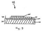
図5を参照する。布製品のラベル付けによく適した熱転写ラベルの5番目の実施形態の略断面図が示され、この熱転写ラベルは、本発明の教示に従って構成され、概して参照番号411により表される。 Please refer to FIG. A schematic cross-sectional view of a fifth embodiment of a thermal transfer label well suited for labeling fabric products is shown, which is constructed in accordance with the teachings of the present invention and is generally designated by
熱転写ラベル411は、熱転写ラベル311にきわめて類似しており、両ラベル間の唯一の相違点は、ラベル411がラベル311のワックス層319に相当する層を含まないことである。 The
図6を参照する。布製品のラベル付けによく適した熱転写ラベルの6番目の実施形態の略断面図が示され、この熱転写ラベルは、本発明の教示に従って構成され、概して参照番号511により表される。 Please refer to FIG. A schematic cross-sectional view of a sixth embodiment of a thermal transfer label well suited for labeling fabric products is shown, which is constructed in accordance with the teachings of the present invention and is generally designated by
熱転写ラベル511は支持部513を含み、支持部513は、キャリヤー515及び剥離層517を含む。キャリヤー515は、ラベル11のキャリヤー15と同一であり、剥離層517は、ラベル11の剥離層17と同一である。 The
また、熱転写ラベル511はワックス層519を含み、ワックス層519は支持部513の剥離層517を被覆している。ワックス層519は、ラベル211のワックス層219と同一であり、かつ約4から20ミクロン、より好ましくは約4から15ミクロンの厚みを有する。 The
更に、熱転写ラベル511は、ワックス層519の所望する領域上に直接印刷されたインキデザイン層525を含む(図6に、ただ1つのインキデザイン層525が示されているが、支持部513に対し1つだけの転写部525を配置する必要はなく、それよりはむしろ、複数の同一又は異なるインキデザイン層525を支持部513の細長い通常のウエブの上に、規則的な間隔をあけて配置することができることが理解される)。 Furthermore, the
インキデザイン層525は、1つのインキ層又は複数のインキ層を実際に含むことができる。好ましくは、インキデザイン層525は、非架橋PVCベースインキを用いて形成される。インキデザイン層525の作成に用いる適切な非架橋PVC含有インキ組成物は、720部のGeon137 PVC樹脂(PolyOne社、エイボンレイク、オハイオ州)、350部のSanticizer160可塑剤(Ferro社、クリーブランド、オハイオ州)、350部のジオクチルフタレート可塑剤(ChemCentral社、ベッドフォードパーク、イリノイ州)、140.4部のVioletPC着色剤(PolyOne社、エイボンレイク、オハイオ州)、77.4部のBlue PC着色剤(PolyOne社、エイボンレイク、オハイオ州)、及び25.2部のBright Yellow PC着色剤(PolyOne社、エイボンレイク、オハイオ州)を含む。 The
好ましくは約0.1から50ミクロン、より好ましくは約1から30ミクロンの厚みを有するインキデザイン層525は、従来の手法で、好ましくはスクリーン印刷により、ワックス層519の1つ又は複数の所望する領域上に上記の種類の1種又は複数のインキ組成物を配置し、かつその後に、層525を形成するためにインキ組成物のすべての揮発成分を蒸発させて、非揮発性インキ成分だけを残すことにより形成される。上記のPVC含有インキの場合、このような揮発性成分が存在せず、しかも印刷層は、典型的にはIR又はUVオーブン中で加熱されて、層を溶融又は「硬化」されなければならない。
容易に理解できるように、ラベルを取り付ける特殊な用途に応じて、インキデザイン層525は、耐久性の取扱注意指示ラベル、企業ID、固体IDなどの表示を組み込むことができる。更に、以下で詳細に述べるように、インキデザイン層525は、偽造検出などの製品セキュリテイのためにラベル付けした製品の判別検査を可能にするために、追加的に又は代替的に「透かし」を組み込むことができ、或いは特定波長の光の照射又は熱で活性化する色素で印刷されたマーキングを組み込むことができる。 As can be readily appreciated, depending on the particular application to which the label is attached, the
ラベル511は、ラベル311と同様な手法で製品に用いることができる。ラベル311より優るラベル511の1つの利点は、ラベル511が接着層を必要としないことである。その結果として、ラベル511の製造法は、ラベル311の製造法ほど複雑ではなく、その結果、必要な材料の減少、製造時間及び費用の減少をもたらす。加えて、ラベル511が、接着層を必要としないので、転写層は、ラベル311に比べて減少した厚み又は容積をもち、ラベル511の転写部をラベル付けした衣料品の着用者の肌を刺激しないようにする。 The
一方、ラベル311を基準にしてラベル511の欠点は、インキデザイン層525下に接着剤層がないことが、ラベル転写時にインキデザイン層525のインキを拡散させる傾向があることである。その結果、インキデザイン層325の解像度に比べて、インキデザイン層525の画像の解像度が劣るようになる傾向がある。したがって、インキデザイン層525は、画像印刷及び小さい文字印刷にインキデザイン層325ほどにはよく適していない。 On the other hand, the disadvantage of the
図7を参照する。布製品のラベル付けによく適した熱転写ラベルの7番目の実施形態の略断面図が示され、この熱転写ラベルは、本発明の教示に従って構成され、概して参照番号611により表される。 Please refer to FIG. Shown is a schematic cross-sectional view of a seventh embodiment of a thermal transfer label well suited for labeling fabric products, the thermal transfer label being constructed in accordance with the teachings of the present invention and generally designated by
熱転写ラベル611は、熱転写ラベル511にきわめて類似しており、両ラベル間の唯一の相違点は、ラベル611がラベル511のワックス層519に相当する層を含まないことである。 The
熱転写ラベル611は、熱転写ラベル511と同様な製品に適用することができる。 The
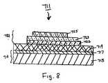
図8を参照する。布製品のラベル付けによく適した熱転写ラベルの8番目の実施形態の略断面図が示され、この熱転写ラベルは、本発明の教示に従って構成され、概して参照番号711により表される。 Please refer to FIG. Shown is a schematic cross-sectional view of an eighth embodiment of a thermal transfer label well suited for labeling fabric products, the thermal transfer label being constructed in accordance with the teachings of the present invention and generally designated by reference numeral 711.
熱転写ラベル711は支持部713を含み、支持部713は、キャリヤー715及び剥離層717を含む。キャリヤー715は、ラベル11のキャリヤー15と同一であり、剥離層717は、ラベル11の剥離層17と同一である。 The thermal transfer label 711 includes a
また、熱転写ラベル711はワックス層719を含み、ワックス層719は支持部713の剥離層717を被覆している。ワックス層719は、ラベル211のワックス層219と同一であり、かつ約4から20ミクロン、より好ましくは約4から15ミクロンの厚みを有する。 The thermal transfer label 711 includes a
更に、熱転写ラベル711は、転写部721を含む(図8に、ただ1つの転写部721が示されているが、支持部713に対し1つだけの転写部721を配置する必要はなく、それよりはむしろ、複数の同一又は異なる転写部721を支持部713の細長い通常のウエブの上に、規則的な間隔をあけて配置することができることが理解される)。転写部721は、好ましくは(i)ワックス層719の所望する領域上に直接印刷されたストレッチ層722、(ii)ストレッチ層722の所望する領域上に直接印刷された熱活性接着剤層723(接着剤層723の底面積はストレッチ層722の底面積を超えない)、及び(iii)接着剤層723の所望する領域上に直接印刷されたインキデザイン層725(インキデザイン層725の底面積は接着層723の底面積を超えない)を含む。 Further, the thermal transfer label 711 includes a transfer portion 721 (only one transfer portion 721 is shown in FIG. 8, but it is not necessary to dispose only one transfer portion 721 with respect to the
ストレッチ層722は、転写部721にある程度の弾力性を与えるもので(転写部721が固着された布のストレッチングに転写部721をよく耐えさせるために)、好ましくは約5から100ミクロン、より好ましくは約10から80ミクロンの厚みを有する。好ましくは、ストレッチ層722は、Hytrel(デュポン社、ウイルミントン、デラウエア州)などの少なくとも1種のポリエステルブロックポリマー、ポリユリアポリマー、及びEstane(Noveon社、クリーブランド、オハイオ州)、Sancure(Noveon社、クリーブランド、オハイオ州)又はNeoRez(NeoResins社、ウイルミントン、マサチューセッツ州)などのポリウレタンポリマーを含む。ストレッチ層722を作成するために用いることができる適切な組成物の例は、50部のSancure835(Noveon社、クリーブランド、オハイオ州)、2部のTafigel PUR61シックナー(Ultra Additives社、クローバー、サウスカロライナ州)、及び0.2部のDehydran1620消泡剤(Cognis社、アンブラー、ペンシルバニア州)を含む。 The stretch layer 722 gives the transfer part 721 a certain degree of elasticity (in order to make the transfer part 721 endure the stretching of the fabric to which the transfer part 721 is fixed), preferably about 5 to 100 microns, more Preferably it has a thickness of about 10 to 80 microns. Preferably, the stretch layer 722 comprises at least one polyester block polymer such as Hytrel (DuPont, Wilmington, Del.), Polyurea polymer, and Estane (Noveon, Cleveland, Ohio), Sancure (Noveon, (Cleveland, Ohio) or NeoRez (NeoResins, Wilmington, Mass.). Examples of suitable compositions that can be used to make the stretch layer 722 are 50 parts Sancure 835 (Noveon, Cleveland, Ohio), 2 parts Tafigel PUR61 thickener (Ultra Additives, Clover, South Carolina). ), And 0.2 parts Dehydran 1620 antifoam (Cognis, Ambler, PA).
ストレッチ層722は、好ましくは、スクリーン印刷、グラビア印刷、又はフレキソ印刷などにより、ワックス層719上に上記の種類のストレッチ組成物を配置し、かつその後に、層722を形成するために組成物の揮発成分を蒸発させて、非揮発性固形成分だけを残すことにより形成される。 Stretch layer 722 is preferably formed by placing a stretch composition of the type described above on
別の実施形態に関連して以下に論じるように、ストレッチ層722は、RFIDマーカー(marker)又は活性化インキで作成されたマーキング(marking)などのセキュリテイ機能を含むように変更できる。 As discussed below in connection with another embodiment, the stretch layer 722 can be modified to include security features such as RFID markers or markings made with activated ink.
接着層723は、ラベル311の接着層323と同一である。 The
転写部721のインキデザイン層725は、1つのインキ層又は複数のインキ層のいずれかを実際に含むことができる。転写ラベルの構造的整合性を維持するために、インキデザイン層725は、接着剤層723と相溶性でなければならず、かつ組成もそれと同様であってもよい。特に、接着剤層723がPVC含有接着性層である場合、インキデザイン層725が、PVCベースインキを用いて形成されることが好ましい。インキデザイン層725製造用の適切なPVC含有インキ組成物の例は、40.6部のGeon137PVC樹脂(PolyOne社、エイボンレイク、オハイオ州)、22.3部のSanticizer160可塑剤(Ferro社、クリーブランド、オハイオ州)、22.3部のジオクチルフタレート可塑剤(ChemCentral社、ベッドフォードパーク、イリノイ州)、5.5部のVioletPC着色剤(PolyOne社、エイボンレイク、オハイオ州)、4.4部のLight Brown PC着色剤(PolyOne社、エイボンレイク、オハイオ州)、及び4.1部のBrightBlue PC着色剤(PolyOne社、エイボンレイク、オハイオ州)を含む。 The
好ましくは約0.1から30ミクロン、より好ましくは約1から20ミクロンの厚みを有するインキデザイン層725は、従来の手法で、好ましくはスクリーン印刷により、接着層723の1つ又は複数の所望する領域上に上記の種類の1種又は複数のインキ組成物を配置し、かつその後に、層725を形成するためにインキ組成物のすべての揮発成分を蒸発させて、非揮発性インキ成分だけを残すことにより形成される。上記のPVC含有インキの場合、このような揮発性成分が存在せず、しかも印刷層は、典型的にはIR又はUVオーブン中で加熱されて、層を溶融又は「硬化」されなければならない。
容易に理解できるように、ラベルを取り付ける特殊な用途に応じて、インキデザイン層725は、耐久性の取扱注意指示ラベル、企業ID、固体IDなどの表示を組み込むことができる。更に、以下で詳細に述べるように、転写部721の少なくとも一つの層(即ち、インキデザイン層725、接着層723、ストレッチ層722)は、偽造検出などの製品セキュリテイのためにラベル付けした製品の判別検査を可能にするために、追加的に又は代替的に「透かし」を組み込むことができ、或いは特定波長の光の照射又は熱で活性化する色素で印刷されたマーキングを組み込むことができる。 As can be readily appreciated, depending on the particular application to which the label is attached, the
ラベル711は、ラベル311と同様な手法で製品に適用できる。 The label 711 can be applied to the product in the same manner as the
図9を参照する。布製品のラベル付けによく適した熱転写ラベルの9番目の実施形態の略断面図が示され、この熱転写ラベルは、本発明の教示に従って構成され、概して参照番号811により表される。 Please refer to FIG. A schematic cross-sectional view of a ninth embodiment of a thermal transfer label well suited for labeling fabric products is shown, which is constructed in accordance with the teachings of the present invention and is generally designated by
熱転写ラベル811は支持部813を含み、支持部813は、キャリヤー815及び剥離層817を含む。キャリヤー815は、ラベル311のキャリヤー315と同一であり、剥離層817は、ラベル311の剥離層317と同一である。 The
また、熱転写ラベル811はワックス層819を含み、ワックス層819はワックス層319と同一であり、かつ支持部813の剥離層817を被覆している。 The
更に、熱転写ラベル811は、転写部821を含む(図9に、ただ1つの転写部821が示されているが、支持部813に対し1つだけの転写部821を配置する必要はなく、それよりはむしろ、複数の同一又は異なる転写部821を支持部813の細長い通常のウエブの上に、規則的な間隔をあけて配置することができることが理解される)。転写部821は、ワックス層819上に直接印刷された接着剤層823、及び接着剤層823上に直接印刷されたインキデザイン層825を含み、接着剤層823は、ラベル311の接着剤層323と同一であり、かつインキデザイン層825は、ラベル311の接着剤層325と同一である。インキデザイン層825が接着剤層823と同一の広がりをもたないことに留意すべきである。その結果、接着剤層823の1つ又は複数の領域又は「窓」が、露出されているか又はインキデザイン層825により被覆されずに残されている。 Furthermore, the
熱転写ラベル811は、更にマーキング827を含み、マーキング827は、インキデザイン層825により被覆されない接着剤層823の前記した「窓」の1つに印刷される(本明細書では、インキデザイン層825及びマーキング827が、接着剤層823上に個別の要素として示されかつ説明されるが、これらは、一緒に機能して、接着剤層823上に単一デザインを形成することは、容易に理解できる)。 The
容易に理解できるように、ラベル811は、マーキング827のような複数のマーキングを含むことができる。更に、インキデザイン層825は、ラベル811から完全に省略することができるが、その際、マーキング827が、ラベル811に描写を望む情報、画像などを包含する。 As can be readily appreciated,
インキデザイン層825は、複数の転写部821にとって不変である情報を伝達するために使用されること、及びマーキング827は、転写部821から転写部821へと変更できる情報を伝達するために使用されることが、現状では考えられる。例えば、インキデザイン層825は、衣料製品に対する取扱説明書又は登録商標を伝達するために使用することができ、一方マーキング827は、所定のラベルに特有の又は一連のラベルに特有の情報を伝達するために使用することができる。マーキング827は、人が読み取り可能な情報及び/又はバーコードなどの機械読み取り可能な情報を含むことができる。可変性マーキング827に含むことができる情報の例は、(a)各ラベルを一意に識別する通し番号、(b)各衣服製品のサイズ(例えば、S、M、Lなど)、スタイル、繊維の種類などの製品特性、(c)価格情報、(d)製造業者又は卸業者の識別又は所在、及び(e)信用情報がある。別法として、インキデザイン層825を省略することができるが、その際マーキング827は、インキデザイン層825により通常伝達される固定情報及び上記の可変情報を伝達するために使用できる。 The
通常、インキデザイン層825は、ラベル製造業者により適用され、その後、マーキング827が、ラベルの転写直前に、ラベルの事業上の利用者(ラベルコンバータとよく呼ばれる;例えば衣料製造業者)により適用される。このようにして、注文ラベルを製造することができ、製造業者が手元に保管しなければならないラベルの在庫量を著しく減少できる。しかし、より一般的には、インキデザイン層825は、マーキング827とともにインラインでインプリント(imprint)できる。マーキング827は、同一位置に、しかもインキデザイン層825を形成するために用いた異なる印刷ラインでインプリントすることができ、またはインキデザイン層825及びマーキング827は、異なる位置に、典型的には異なる製造業者によりインプリントできる。 Typically, the
好ましくは、マーキング827は、種々の印刷技術、即ち熱転写印刷(好ましくはニアーエッジ(near−edge)熱転写印刷)、インクジェット印刷、レーザー印刷などを用いて形成するので、注文レベルが必要に応じて作成できる(また、マーキング827は、グラビア印刷、スクリーン印刷、及びフレキソ印刷などのその他の印刷技術により作成することもできるが、しかしこれらの技術は種々の情報を印刷するには余り適していない)。容易に理解できるように、熱転写プリンター、インクジェットプリンター、レーザープリンター又は類似装置は、コンピュータに接続して、コンピュータを用いて発生させ又は選択したデジタル画像をプリンターにより印刷することができる。このようなコンピュータは、独立型パソコンであってもよく、又は中央処理装置又はインターネットなどを通してネットワークに接続したコンピュータでもよい。 Preferably, the marking 827 is formed using various printing techniques, namely thermal transfer printing (preferably near-edge thermal transfer printing), ink jet printing, laser printing, etc., so that the order level can be created as needed. (The marking 827 can also be made by other printing techniques such as gravure printing, screen printing, and flexographic printing, but these techniques are not well suited for printing a variety of information). As can be readily appreciated, a thermal transfer printer, ink jet printer, laser printer or similar device can be connected to a computer to print a digital image generated or selected using the computer. Such a computer may be a stand-alone personal computer or a computer connected to a network through a central processing unit or the Internet.
ラベル311に関連して指摘したように、接着剤層823上に印刷した事項の可読性は、接着剤層823の表面粗さと大いに関係する。したがって、接着剤層823の印刷表面が、約15ミクロン超の表面粗さを有する場合、印刷品質はむしろ貧弱になる傾向である(この可読性の問題は、熱転写印刷などの技術により印刷されたマーキングの厚みが1ミクロンのオーダーであるから、このような技術を用いてマーキングを印刷する場合に悪化する)。それ故、接着剤層823の表面粗さは、約10ミクロン以下であることが好ましく、かつ(文字列に対立する)図形を又は小さい書体の文字列を印刷したい場合には、約5ミクロンであることがより好ましい。したがって、高解像度が必要とされる用途では、ラベル311に関連して上に述べたPVCベースの接着剤が好んで用いられ、このPVCベースの接着剤は1ミクロンより小さい表面粗さをもつ。比較すれば、このような高解像度が必要とされない場合、ラベル311に関連して上に述べたポリエステルベースの接着剤を別法として用いることができる。このポリエステルベースの接着剤は、約6から10ミクロンの表面粗さをもっている。 As pointed out in connection with
また、マーキング827を作成するために熱転写印刷法を用いる場合に留意すべきことは、樹脂ベースのインキ転写リボンが、樹脂及びワックスベースのインキ転写リボンより高解像度のマーキングを生成するが、一方で樹脂及びワックスベースのインク転写リボンは、樹脂ベースのインキ転写リボンより高いコントラスト比(即ち黒色度)を生成することが判明したことである。それ故、高解像度か又は高コントラストのいずれを望むかにより、適切なインキ転写リボンを選択できる。 Also note that when using thermal transfer printing methods to create the marking 827, resin-based ink transfer ribbons produce higher resolution markings than resin and wax-based ink transfer ribbons, while It has been found that resin and wax-based ink transfer ribbons produce higher contrast ratios (ie, blackness) than resin-based ink transfer ribbons. Therefore, an appropriate ink transfer ribbon can be selected depending on whether high resolution or high contrast is desired.
マーキング827は、本明細書では接着剤層823の窓に配置させるように説明されているが、マーキング827をインキデザイン層825の一部又は全体と連携させて、例えば、真正証明などを作成できる。 Although the marking 827 is described in this specification as being placed in the window of the
ラベル811は、ラベル311と同様な手法で製品に適用できる。 The
また、ラベル711で記載した手法と同様に、ラベル811は、マーキング(好ましくは、熱転写印刷、インクジェット印刷、レーザー印刷などで作成した)を含むことができ、このようなマーキングは、接着層823上に直接印刷される。 Also, similar to the technique described for label 711,
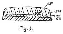
図10を参照する。布製品のラベル付けによく適した熱転写ラベルの10番目の実施形態の略断面図が示され、この熱転写ラベルは、本発明の教示に従って構成され、概して参照番号851により表される。 Please refer to FIG. A schematic cross-sectional view of a tenth embodiment of a thermal transfer label well suited for labeling fabric products is shown, which is constructed in accordance with the teachings of the present invention and is generally designated by
熱転写ラベル851は、大多数の点で熱転写ラベル211に類似しているが、2つのラベル間の主要な相違点は、熱転写ラベル851が、インキデザイン層225の開口域と連携した領域の接着層227上に直接印刷されたマーキング853を更に含むことである。マーキング853は、ラベル811のマーキング827と同様な手法で形成されることが好ましい。 The
容易に理解できるように、ラベル851は、マーキング853のような複数のマーキングを含むことができる。更に、インキデザイン層225をラベル851から完全に省くことができ、その際、マーキング853が、ラベル851に描写を所望するどのような情報、画像でも包含する。 As can be readily appreciated,
更に、マーキング853は、本明細書ではインキデザイン層225の開口域と連携させるように説明されているが、マーキング853をインキデザイン層225の一部又は全体と連携させて、例えば、真正証明などを作成できる。 Further, although the marking 853 is described in this specification so as to be associated with the opening area of the
ラベル851は、ラベル211と同様な手法で製品に適用できる。 The
容易に理解できるように、上記の種類の熱転写ラベルにセキュリテイ機能(例えば、盗難防止、偽造防止、平行輸入防止など)、在庫追跡機能などを組み込むことが望ましい。本発明の教示に従えば、この目的を完遂する1つのアプローチは、RFID(無線認証)素子を熱転写ラベルに組み入れることである。このRFID素子は、セキュリテイ目的のための情報及び/又は広範囲のその他の種類の情報を含むことができる。RFID素子に含むことができる情報の例は、(a)各RFIDラベルを一意に識別する通し番号、(b)衣料製品のそれぞれのサイズ(例えば、S、M、L)、スタイル、繊維の種類などの製品特性、(c)価格情報、(d)製造業者又は卸売業者の認証又は所在、及び(e)真正情報を含む。 For easy understanding, it is desirable to incorporate a security function (for example, anti-theft, forgery prevention, parallel import prevention), an inventory tracking function, etc. into the above-mentioned type of thermal transfer label. In accordance with the teachings of the present invention, one approach to accomplishing this goal is to incorporate an RFID (wireless authentication) element into the thermal transfer label. The RFID element may contain information for security purposes and / or a wide range of other types of information. Examples of information that can be included in an RFID element include: (a) a serial number that uniquely identifies each RFID label; (b) the size (eg, S, M, L) of each clothing product, style, fiber type, etc. Product characteristics, (c) price information, (d) manufacturer or wholesaler certification or location, and (e) authentic information.
図11を参照する。布製品のラベル付けによく適した熱転写ラベルの11番目の実施形態の略断面図が示され、この熱転写ラベルは、本発明の教示に従って構成され、概して参照番号911により表される。 Please refer to FIG. Shown is a schematic cross-sectional view of an eleventh embodiment of a thermal transfer label well suited for labeling fabric products, which is constructed in accordance with the teachings of the present invention and is generally designated by
熱転写ラベル911は、大多数の点で熱転写ラベル211に類似しているが、2つのラベル間の主要な相違点は、ラベル911が、造り付けアンテナを具えたRFID集積回路912を更に含むことである。RFID集積回路912は、プライマー層226と接着剤層227の間に挟まれている。好ましくは、RFID集積回路912は、ラベル911の容積を減少させるためにきわめて薄く作られている。RFID集積回路912用の造り付けアンテナを具えたRFID集積回路の例は、ヒタチ社から「ミューチップ(mu−chip)」RFIDICとして市場から入手できる。この「ミューチップ」RFID ICは、0.4mm×0.4mmのサイズをもち、無線周波数2.45Ghzで機能し、128ビットのROMを有する。プライマー層226と接着剤層227の間にRFID集積回路912の実装は、プライマー層226上にRFID集積回路912を配置し(プライマー層226が乾燥する前に)、次にRFID集積回路912及びプライマー層226上に接着剤層227を印刷することにより行うことができる。 The
ラベル911は、ラベル211と同様な手法で製品に適用できる。 The
造り付けアンテナを具えたRFID集積回路を更に含む熱転写ラベルの別の実施形態が、図12に示される。この熱転写ラベルは、本発明の教示に従って構成され、概して参照番号1011により表される。熱転写ラベル1011は、大多数の点で熱転写ラベル111に類似しているが、ラベル111との相違点は、ラベル1011が、接着剤層227とプライマー層226の間に配置されたRFID集積回路1012を更に含むことであり、RFID集積回路1012は、RFID集積回路912と同一である。 Another embodiment of a thermal transfer label further comprising an RFID integrated circuit with a built-in antenna is shown in FIG. This thermal transfer label is constructed in accordance with the teachings of the present invention and is generally designated by
示されていないが、RFID集積回路912又はRFID集積回路1012のようなRFID集積回路を同じような方法で熱転写ラベル11に挿入できることを理解すべきである。代わりに、RFIDIC912又はRFID IC1012のようなRFID ICをラベル311、411及び711のそれぞれのインキデザイン層と接着剤層の間に挿入できる。 Although not shown, it should be understood that an RFID integrated circuit such as RFID integrated
図13を参照する。布製品のラベル付けによく適した熱転写ラベルの13番目の実施形態の略断面図が示され、この熱転写ラベルは、本発明の教示に従って構成され、概して参照番号1111により表される。 Please refer to FIG. A schematic cross-sectional view of a thirteenth embodiment of a thermal transfer label well suited for labeling fabric products is shown, which is constructed in accordance with the teachings of the present invention and is generally designated by reference numeral 1111.
熱転写ラベル1111は、大多数の点で熱転写ラベル911に類似しているが、2つのラベル間の主要な相違点は、ラベル1111が、RFIDIC912の代わりに、接着剤層227とプライマー層226の間に挿入されたRFIDストラップ1113を含むことである。「RFIDストラップ」は、RFIDチップ及び導電性リードの組み合わせを含む。RFIDストラップの例は、以下の特許及び特許出願に開示されており、これらの全てを参考として本明細書に援用する:米国特許出願公報2003/0136503、名称「RFIDラベル技術」、発明者Greenら、2003年7月24日公告;米国特許出願番号10/214,066、名称「無線認証素子及び方法」、発明者Liuら、2002年8月7日出願;米国特許出願番号10/406,702、名称「RFID素子検出システム及び方法」、発明者Forster、2003年4月3日出願;米国特許出願番号60/485,313、名称「可変特性を有するRFID素子」、発明者Forsterら、2003年7月7日出願;及び米国特許出願番号60/517,155、名称「高判読率のRFIDタグ」、発明者Forster、2003年11月4日出願。加えて、RFIDストラップは、PhilipsElectronics社(オランダ)から「I−コネクト」RFIDストラップとして市場で入手できる。 The thermal transfer label 1111 is similar to the
ラベル1111は、ラベル911と同様な手法で製品に適用できる。 The label 1111 can be applied to the product in the same manner as the
示されていないが、RFIDストラップ1113のようなRFIDストラップを同じような方法で熱転写ラベル11に挿入できることを理解すべきである。代わりに、RFIDストラップ1113のようなRFIDストラップをラベル311、411及び711のそれぞれのインキデザイン層と接着剤層の間に挿入できる。 Although not shown, it should be understood that an RFID strap such as RFID strap 1113 can be inserted into thermal transfer label 11 in a similar manner. Alternatively, an RFID strap such as RFID strap 1113 can be inserted between each ink design layer and adhesive layer of
無線RFID及びRFIDストラップの読み取り距離は、きわめて小さく即ち約1インチであることに留意すべきである。したがって、ラベル911、1011、1111内のRFID情報は、リーダーがきわめて接近して配置された時にだけ読み取りできる。より長い距離での読み取りを可能にするために、RFID素子がアンテナを含むことが好ましい。 It should be noted that the reading distance of the wireless RFID and RFID strap is very small, ie about 1 inch. Thus, the RFID information in the
図14を参照する。布製品のラベル付けによく適した熱転写ラベルの14番目の実施形態の略断面図が示され、この熱転写ラベルは、本発明の教示に従って構成され、概して参照番号1211により表される。 Refer to FIG. A schematic cross-sectional view of a fourteenth embodiment of a thermal transfer label well suited for labeling fabric products is shown, which is constructed in accordance with the teachings of the present invention and is generally designated by
熱転写ラベル1211は支持部1213を含み、支持部1213は、キャリヤー1215及び剥離層1217を含む。キャリヤー1215は、ラベル11のキャリヤー15と同一であり、剥離層1217は、ラベル11の剥離層17と同一である。 The
また、熱転写ラベル1211は、支持部1213の剥離層1217を被覆するワックス層1219を含み、ワックス層1219はワックス層219と同一である。 The
熱転写ラベル1211は、転写部1221を更に含む(図14に、ただ1つの転写部1221が示されているが、支持部1213に対し1つだけの転写部1221を配置する必要はなく、それよりはむしろ、複数の同一又は異なる転写部1221を支持部1213の細長い通常のウエブの上に、規則的な間隔をあけて配置することができることが理解される)。転写部1221は、(i)ワックス層1219の所望する領域上に直接印刷されたインキデザイン層1225であって、好ましくはラベル211のインキデザイン層225と同一であるインキデザイン層1225、(ii)インキデザイン層1225上(並びにインキデザイン層1225内のワックス層1219の任意の露出された領域上)及びワックス層1219の周辺領域上に直接印刷されたマスク層1226であって、好ましくはラベル211のインキデザイン層225に類似するが、しかし、ラベル転写後、以下に説明するRFID素子を視界から覆い隠す不透明品質を有するマスク層1226、(iii)マスク層1226上に直接印刷されたプライマー層1227であって、好ましくはラベル211のプライマー層226と同一であるプライマー層1227、(iv)プライマー層1227上に直接印刷されたアンテナ1228であって、スクリーン印刷又はフレキソ印刷などの標準的印刷技術を用いて銀インキで印刷したアンテナ1228、(v)従来のチップ取付け技術及び非等方性導電性ペースト又はフィルムなどの普通の接着剤を用いてアンテナ1228に結合したRFIDチップ1229、及び(vi)RFIDチップ1229、アンテナ1228及びプライマー1227の任意の露出された領域、及びワックス層1219の周辺領域上に直接印刷された熱活性接着層227を含む。 The
ラベル1211は、ラベル1111と同様な手法で製品に適用できる。 The
図15を参照する。布製品のラベル付けによく適した熱転写ラベルの15番目の実施形態の略断面図が示され、この熱転写ラベルは、本発明の教示に従って構成され、概して参照番号1311により表される。 Refer to FIG. Shown is a schematic cross-sectional view of a fifteenth embodiment of a thermal transfer label well suited for labeling fabric products, which is constructed in accordance with the teachings of the present invention and is generally designated by
熱転写ラベル1311は支持部1313を含み、支持部1313は、キャリヤー1315及び剥離層1317を含む。キャリヤー1315は、ラベル11のキャリヤー15と同一であり、剥離層1317は、ラベル11の剥離層17と同一である。 The
また、熱転写ラベル1311は、支持部1313の剥離層1317を被覆するワックス層1319を含み、ワックス層1319はワックス層219と同一である。 The
熱転写ラベル1311は、転写部1321を更に含む(図15に、ただ1つの転写部1321が示されているが、支持部1313に対し1つだけの転写部1321を配置する必要はなく、それよりはむしろ、複数の同一又は異なる転写部1321を支持部1313の細長い通常のウエブの上に、規則的な間隔をあけて配置することができることが理解される)。転写部1321は、ワックス層1319の所望する領域上に直接印刷されたインキデザイン層1325を含み、インキデザイン層1325が、ラベル211のインキデザイン層225と同一であることが好ましい。 The
また、転写部1321はマスク層1326を含み、マスク層1326は、インキデザイン層1325上(並びにインキデザイン層1325内のワックス層1319の任意の露出された領域上)及びワックス層1319の周辺領域上に直接印刷される。マスク層1326は、好ましくはラベル211のインキデザイン層225に類似するが、しかし、ラベル転写後、以下に説明するRFID素子を視界から覆い隠す不透明品質を有する。 Further, the transfer portion 1321 includes a mask layer 1326, which is on the ink design layer 1325 (and on any exposed area of the
転写部1321は、マスク層1326上に直接印刷したプライマー層1327を更に含み、プライマー層1327が、ラベル211のプライマー層226同一であることが好ましい。 The transfer portion 1321 further includes a primer layer 1327 printed directly on the mask layer 1326, and the primer layer 1327 is preferably the same as the
転写部1321は、感圧接着剤1328、RFIDチップ1329、及びアンテナ1330のサブコンビネーションを更に含み、このサブコンビネーションは以下のように形成される(図16を参照のこと)。先ず、アンテナ1330が、銀インキ及び従来のアンテナ印刷技術を用いて剥離ライナー1331上に印刷される。次に、RFIDチップ1329が、従来のチップボンデイング技術を用いてアンテナ1330に取り付けられる。その後、感圧接着剤1328が、アンテナ1330及びチップ1329上、及び剥離ライナー1331上に印刷される。このように形成して、このサブコンビネーションが逆転させられ、感圧接着剤1328が、プライマー層1327と接触させられる。次に、剥離ライナー1331が、アンテナ1330及び感圧接着剤1328から除去される。最後に、熱活性接着剤1332が、このようにして露出させられた、アンテナ1330及び感圧接着剤1328、並びにワックス層1319の周辺領域上に直接印刷される。 The transfer unit 1321 further includes a sub-combination of the pressure-
ラベル1311は、ラベル1211と同様な手法で製品に適用できる。 The
プライバシーの論点から、RFID素子が取り付けられた衣料品が消費者に販売された後直ちに、このRFID素子が作動不能になることが望ましい。RFID素子を作動不能にする一つの方法は、水溶性インキを用いてRFIDアンテナを印刷することである。この手法では、衣料品を水洗した時に、アンテナが溶解して、RFID素子が作動不能になる。別の手法は、ラベル中にRFID素子を保持する領域(ラベルの図形を保持する領域ではなく)に水溶性接着剤を用いることである。この手法では、衣料品を水洗した時に、接着剤が溶解して、RFID素子がラベルから洗浄除去される。 From a privacy point of view, it is desirable that the RFID element becomes inoperable immediately after the garment with the RFID element attached is sold to the consumer. One way to render the RFID element inoperable is to print the RFID antenna with water-soluble ink. In this method, when the clothes are washed with water, the antenna is dissolved and the RFID element becomes inoperable. Another approach is to use a water-soluble adhesive in the area holding the RFID element in the label (rather than the area holding the label graphic). In this method, when the garment is washed with water, the adhesive dissolves and the RFID element is washed away from the label.
上記の種々の熱転写ラベルにセキュリテイ機能(盗難防止、偽造防止、並行輸入防止)又は在庫管理メカニズムを付与できる別な方法は、1つ又は複数のセキュリテイ材料(インキ及び添加剤など)をラベルに組み込むことである。セキュリテイ材料は、ラベルの単一層(インキ層又は接着剤層など)を含むか又はこの層に添加されてもよく、又はセキュリテイ表示を与えるために相互作用するラベルの複数層を含んでもよい。容易に目に見える(又は「歴然とした」)セキュリテイ標識は、一般的に隠されたセキュリテイより好ましい。 Another method that can provide security features (anti-theft, anti-counterfeiting, parallel import prevention) or inventory control mechanisms to the various thermal transfer labels described above incorporate one or more security materials (such as inks and additives) into the label That is. The security material may include or be added to a single layer of labels (such as an ink layer or an adhesive layer), or may include multiple layers of labels that interact to provide a security indication. Easily visible (or “obvious”) security labels are generally preferred over hidden security.
セキュリテイインキは、IR活性インキ、UV活性インキ、可視光活性インキ、熱活性インキ、電気活性インキ、磁気活性インキ、化学活性インキ、圧力活性インキ、2色性インキ、時間制御インキを含むが、これらに限定されない。 Security ink includes IR active ink, UV active ink, visible light active ink, thermal active ink, electroactive ink, magnetic active ink, chemically active ink, pressure active ink, dichroic ink, and time control ink. It is not limited to.
セキュリテイ添加剤は、例えば、熱転写ラベルの接着剤層に組み込むことができる微視的トレーサー粒子を含む。ある種の分子は、それらの物理的材料組成、色、文字数字記号、及びその他の方法によりコード化できる。熱転写ラベルのこの分子組成の検査には、電子リーダーが使用できる。 Security additives include, for example, microscopic tracer particles that can be incorporated into the adhesive layer of a thermal transfer label. Certain molecules can be encoded by their physical material composition, color, letter symbols, and other methods. An electronic reader can be used to inspect this molecular composition of the thermal transfer label.
セキュリテイインキの例として、図17を参照する。布製品のラベル付けによく適した熱転写ラベルの16番目の実施形態の略断面図が示され、この熱転写ラベルは、本発明の教示に従って構成され、概して参照番号1411により表される。 FIG. 17 is referred to as an example of the security ink. A schematic cross-sectional view of a sixteenth embodiment of a thermal transfer label well suited for labeling fabric products is shown, which is constructed in accordance with the teachings of the present invention and is generally designated by
熱転写ラベル1411は、大多数の点で熱転写ラベル1311に類似しているが、2つのラベル間の主要な相違点は、ラベル1411が、インキ層325の代わりに、従来のインキデザイン1423を含むインキ層、サーモクロミックインキデザイン1425、及びマーキング1427を含むことである。従来のインキデザイン1423は、同様な手法及びインキ層325と同種のインキを用いて接着剤層323の上に印刷できる。サーモクロミックインキデザイン1425は、サーモクロミックインキが非サーモクロミックインキの代わりに用いられることを除いては、従来のインキデザイン1423と同様な手法で、接着剤層323の上に印刷できる。サーモクロミックインキデザイン1425は、製品ロゴの型式で真正証明などのセキュリテイ機能として用いることができる。加熱された時(例えば、可搬ヒーターを用いて)、製品ロゴの外観が変色して、その製品が商品として認定されているか又は非認定であるかを当事者に情報伝達する。インキ層1425の印刷に適したサーモクロミックインキの例は、MatuiInternational社(ガーデナ、カリフォルニア州)からChromicolor Fast Blueインキとして市場で入手できる。 The
マーキング1427は、同様な手法及びマーキング827と同種のインキを用いて接着剤層323の上に印刷でき、かつ変更可能な印刷情報などのマーキング827と同種の情報を描写するために用いることができる。 The marking 1427 can be printed on the
ラベル1411は、ラベル311と同様な手法で製品に適用できる。 The
図18を参照する。布製品のラベル付けによく適した熱転写ラベルの17番目の実施形態の略断面図が示され、この熱転写ラベルは、本発明の教示に従って構成され、概して参照番号1511により表される。 Please refer to FIG. A schematic cross-sectional view of a seventeenth embodiment of a thermal transfer label well suited for labeling fabric products is shown, which is constructed in accordance with the teachings of the present invention and is generally designated by
熱転写ラベル1511は、大多数の点で熱転写ラベル311に類似しているが、2つのラベル間の主要な相違点は、ラベル1511が、接着剤層323の代わりに、接着剤層1523を含むことである。接着剤層1523は、この層が光活性顔料を更に含む点で層323と異なる。したがって、層1523は、特定の波長の光で活性化された時、識別光を発光することによりセキュリテイ(例えば、偽造防止)層として機能する。層1523形成に適した接着組成物の例は、100部のGeon137(PolyOne社、クリーブランド、オハイオ州)、55部のSanticizer 160可塑剤(Ferro社、クリーブランド、オハイオ州)、55部のジオクチルフタレート可塑剤(ChemCentral社、ベッドフォードパーク、イリノイ州)、及び21部のLumiNovaBG−300M燐光顔料(UMC社、リンドハースト、ニュージャージ州)を含む。 The
別法として、接着剤層1523をPhotopai Purple UV感応インキ(Matui International社、ガーデナ、カルフォルニア州)で印刷されたインキ層と置き換えることができる。 Alternatively, the
ラベル1511は、ラベル311と同様な手法で製品に適用できる。 The
図19を参照する。布製品のラベル付けによく適した熱転写ラベルの18番目の実施形態の略断面図が示され、この熱転写ラベルは、本発明の教示に従って構成され、概して参照番号1611により表される。 Refer to FIG. Shown is a schematic cross-sectional view of an eighteenth embodiment of a thermal transfer label well suited for labeling fabric products, the thermal transfer label being constructed in accordance with the teachings of the present invention and generally designated by
熱転写ラベル1611は、大多数の点で熱転写ラベル311に類似しているが、2つのラベル間の主要な相違点は、ラベル1611が、インキデザイン層325上に直接印刷された第二のインキデザイン層1613を更に含むことである。層1613及び層325は、重なるこれらの領域が重ならない領域と区別される(例えば、色で)ように選択される。例えば、層325は黄色横帯線を含んでもよく、かつ層1613は青色縦帯線を含んでもよく、その結果、黄色と青色帯線が交差する場所に緑色領域が現れるであろう。層325が、ラベル製造業者により第1の位置に印刷され、層1613が、熱転写プリンター、インクジェットプリンター、レーザープリンターなどを用いて衣料製造業者(ラベルコンバータ)により第2の位置に印刷されるであろうと言うことが、現時点で考えられる。この手法では、ラベルコンバータが、ラベルを選択的に「活性化する」ことができる。 The
上記の手法で、相互作用して物理的色変化を起こす代わりに、層1613及び層325が、互いに重なった時に、化学反応を受けるように調合することもできると理解されるべきである。 It should be understood that instead of interacting and causing a physical color change in the manner described above, layer 1613 and
ラベル1611は、ラベル311と同様な手法で製品に適用できる。 The
図20を参照する。布製品のラベル付けによく適した熱転写ラベルの19番目の実施形態の略断面図が示され、この熱転写ラベルは、本発明の教示に従って構成され、概して参照番号1651により表される。 Refer to FIG. A schematic cross-sectional view of a nineteenth embodiment of a thermal transfer label well suited for labeling fabric products is shown, which is constructed in accordance with the teachings of the present invention and is generally designated by
熱転写ラベル1651は、大多数の点で熱転写ラベル211に類似しているが、2つのラベル間の主要な相違点は、ラベル1651が、接着剤層227上に直接印刷された第二のインキデザイン層1653を更に含むことである。層1653及び225は、重なるこれらの領域が重ならない領域と区別される(例えば、色で)ように選択される。例えば、層225は黄色横帯線を含んでもよく、かつ層1653は青色縦帯線を含んでもよく、その結果、黄色と青色帯線が交差する場所に緑色領域が現れるであろう。層225が、ラベル製造業者により第1の位置に印刷され、層1653が、熱転写プリンター、インクジェットプリンター、レーザープリンターなどを用いて衣料製造業者により第2の位置に印刷されるであろうと言うことが、現時点で考えられる。この手法では、製造業者が、ラベルを選択的に「活性化する」ことができる。 The
ラベル1651は、ラベル211と同様な手法で製品に適用できる。 The
図21を参照する。布製品のラベル付けによく適した熱転写ラベルの20番目の実施形態の略断面図が示され、この熱転写ラベルは、本発明の教示に従って構成され、概して参照番号1711により表される。 Refer to FIG. A schematic cross-sectional view of a twentieth embodiment of a thermal transfer label well suited for labeling fabric products is shown, which is constructed in accordance with the teachings of the present invention and is generally designated by reference numeral 1711.
熱転写ラベル1711は、大多数の点で熱転写ラベル211に類似しているが、2つのラベル間の主要な相違点は、ラベル1711が、接着剤層227上に直接印刷されたインキデザイン層1725を更に含むことである。好ましくは、熱転写印刷又は同様なデジタル印刷技術により作成されるインキデザイン層1725は、デジタルコード記号化情報が画像画素のマトリックス内に定位置画素として埋め込まれている画像を含む。デジタルコードは、肉眼には目立たないが、埋め込まれたデジタルコードを検出するようにプログラムされたデジタルリーダーにより読むことができる。 The thermal transfer label 1711 is similar to the
熱転写ラベル1711は、ラベル211と同様な手法で製品に適用できる。 The thermal transfer label 1711 can be applied to a product in the same manner as the
図22を参照する。布製品のラベル付けによく適した熱転写ラベルの21番目の実施形態の略断面図が示され、この熱転写ラベルは、本発明の教示に従って構成され、概して参照番号1751により表される。 Refer to FIG. A schematic cross-sectional view of a twenty-first embodiment of a thermal transfer label well suited for labeling fabric products is shown, which is constructed in accordance with the teachings of the present invention and is generally designated by
熱転写ラベル1751は、大多数の点で熱転写ラベル311に類似しているが、2つのラベル間の主要な相違点は、ラベル1751がインキデザイン層1753を含み、この層1753が、好ましくは熱転写印刷又は同様なデジタル印刷技術により作成され、デジタルコード記号化情報が画像画素のマトリックス内に定位置画素として埋め込まれている画像を含むことである。デジタルコードは、肉眼には目立たないが、埋め込まれたデジタルコードを検出するようにプログラムされたデジタルリーダーにより読むことができる。 The
熱転写ラベル1751は、ラベル311と同様な手法で製品に適用できる。 The
本明細書に引用された本発明の実施形態は、単なる代表例であると思考するものであり、当業者は、本発明の精神から離れることなく多くの変更及び変性を行うことができるであろう。例えば、出願人の発明の観点から逸脱することなく、本明細書に「非ワックス」及び「非シリーコン」として説明した剥離層に、直接又は層横断移行により微量の又は感知不能な微少量のワックス又はシリコーンを加えることができることを理解すべきである。このように、本明細書に用いる用語「非ワックス」及び「非シリーコン」は、この可能性を包含することを意図している。このような変更及び変性の全ては、本明細書に添付した特許請求の範囲により定義される本発明の範囲内であると思考される。 The embodiments of the invention cited herein are considered merely representative and one of ordinary skill in the art can make many changes and modifications without departing from the spirit of the invention. Let ’s go. For example, without departing from the viewpoint of Applicant's invention, the release layer described herein as “non-wax” and “non-silicone” can be traced to trace amounts or insensitive amounts by direct or cross-layer transition. Or it should be understood that silicone can be added. Thus, the terms “non-wax” and “non-silicone” as used herein are intended to encompass this possibility. All such changes and modifications are considered to be within the scope of the invention as defined by the claims appended hereto.
11 熱転写ラベル
13 支持部
15 キャリヤー
17 剥離層又はコーテイング
21 転写部
23 保護ラッカー層
25 インキデザイン層
26 プライマー層
27 熱活性接着剤層
111 熱転写ラベル
113 支持部
115 キャリヤー
117 剥離層
121 転写部
125 インキデザイン層
126 プライマー層
127 熱活性接着剤層
211 熱転写ラベル
213 支持部
215 キャリヤー
217 剥離層
219 ワックス層
221 転写部
225 インキデザイン層
226 プライマー層
227 熱活性接着剤層
311 熱転写ラベル
313 支持部
315 キャリヤー
317 剥離層
319 ワックス層
321 転写部
323 熱活性接着剤層
325 インキデザイン層
411 熱転写ラベル
511 熱転写ラベル
513 支持部
515 キャリヤー
517 剥離層
519 ワックス層
525 インキデザイン層
611 熱転写ラベル
711 熱転写ラベル
713 支持部
715 キャリヤー層
717 剥離層
719 ワックス層
721 転写部
722 ストレッチ層
723 熱活性接着剤層
725 インキデザイン層
811 熱転写ラベル
813 支持部
815 キャリヤー
817 剥離層
819 ワックス層
821 転写部
823 接着剤層
825 インキデザイン層
827 マーキング
851 熱転写ラベル
853 マーキング
911 熱転写ラベル
912 RFID集積回路
1011 熱転写ラベル
1012 RFID集積回路
1111 熱転写ラベル
1113 RFIDストラップ
1211 熱転写ラベル
1213 支持部
1215 キャリヤー
1217 剥離層
1219 ワックス層
1221 転写部
1225 インキデザイン層
1226 マスク層
1227 プライマー層
1228 アンテナ
1229 RFIDチップ
1311 熱転写ラベル
1313 支持部
1315 キャリヤー
1317 剥離層
1319 ワックス層
1325 インキデザイン層
1326 マスク層
1327 プライマー層
1328 感圧接着剤
1329 RFIDチップ
1330 アンテナ
1331 剥離ライナー
1332 熱活性接着剤
1411 熱転写ラベル
1423 インキデザイン
1425 サーモクロミックインキデザイン
1427 マーキング
1511 熱転写ラベル
1523 接着剤層
1611 熱転写ラベル
1613 インキデザイン層
1651 熱転写ラベル
1653 インキデザイン層
1711 熱転写ラベル
1725 インキデザイン層
1751 熱転写ラベル
1753 インキデザイン層DESCRIPTION OF SYMBOLS 11 Thermal transfer label 13 Support part 15 Carrier 17 Release layer or coating 21 Transfer part 23 Protective lacquer layer 25 Ink design layer 26 Primer layer 27 Thermally active adhesive layer 111 Thermal transfer label 113 Support part 115 Carrier 117 Release layer 121 Transfer part 125 Ink design Layer 126 Primer layer 127 Thermally active adhesive layer 211 Thermal transfer label 213 Support part 215 Carrier 217 Release layer 219 Wax layer 221 Transfer part 225 Ink design layer 226 Primer layer 227 Thermally active adhesive layer 311 Thermal transfer label 313 Support part 315 Carrier 317 Release Layer 319 Wax layer 321 Transfer part 323 Thermally active adhesive layer 325 Ink design layer 411 Thermal transfer label 511 Thermal transfer label 513 Support part 515 Carrier 517 Release layer 519 Wack Layer 525 Ink design layer 611 Thermal transfer label 711 Thermal transfer label 713 Support part 715 Carrier layer 717 Release layer 719 Wax layer 721 Transfer part 722 Stretch layer 723 Thermally active adhesive layer 725 Ink design layer 811 Thermal transfer label 813 Support part 815 Carrier 817 Release Layer 819 Wax layer 821 Transfer part 823 Adhesive layer 825 Ink design layer 827 Marking 851 Thermal transfer label 853 Marking 911 Thermal transfer label 912 RFID integrated circuit 1011 Thermal transfer label 1012 RFID integrated circuit 1111 Thermal transfer label 1113 RFID strap 1211 Thermal transfer label 1213 Support part 1215 Carrier 1217 Release layer 1219 Wax layer 1221 Transfer portion 1225 Ink design layer 1226 Mask layer 1227 Laminar layer 1228 Antenna 1229 RFID chip 1311 Thermal transfer label 1313 Support portion 1315 Carrier 1317 Release layer 1319 Wax layer 1325 Ink design layer 1326 Mask layer 1327 Primer layer 1328 Pressure sensitive adhesive 1329 RFID chip 1330 Antenna 1331 Release liner 1332 Thermally active adhesive 1411 Thermal transfer label 1423 Ink design 1425 Thermochromic ink design 1427 Marking 1511 Thermal transfer label 1523 Adhesive layer 1611 Thermal transfer label 1613 Ink design layer 1651 Thermal transfer label 1653 Ink design layer 1711 Thermal transfer label 1725 Ink design layer 1751 Thermal transfer label 1753 Ink design layer
Claims (6)
Translated fromJapaneseキャリヤーを備えており、このキャリヤーの一方の面は、前記インキデザイン層および前記マーキングの剥離コーティングと、前記インキデザイン層に印刷された不変情報と、前記マーキングに印刷された可変情報と、前記インキデザイン層および前記マーキングの接着剤層とを支持しており、
前記剥離コーティングは、前記キャリヤーと前記インキデザイン層に印刷された不変情報との間、及び、前記キャリヤーと前記マーキングに印刷された可変情報との間に配置されており、
前記インキデザイン層の印刷された不変情報は、前記接着剤層と前記剥離コーティングの間に配置されており、
RFID ICが、前記インキデザイン層と前記接着剤層との間に配置されており、
前記接着剤層は、前記マーキングに印刷された可変情報と前記剥離コーティングとの間に配置されていることを特徴とする熱転写ラベル。A thermal transfer label with one or more ink design layers capable of receiving printed invariant information and one or more markings capable of receiving printed variable information,
One side of the carrier comprises a release coating of the ink design layer and the marking, invariant information printed on the ink design layer, variable information printed on the marking, and the ink Supports the design layer and the adhesive layer of the marking,
The release coating is disposed between the carrier and immutable information printed on the ink design layer and between the carrier and variable information printed on the marking;
The printed invariant information of the ink design layer is disposed between the adhesive layer and the release coating,
RFID IC is disposed between the ink design layer and the adhesive layer,
The thermal transfer label, wherein the adhesive layer is disposed between the variable information printed on the marking and the release coating.
請求項1に記載の熱転写ラベルを供給する工程と、
接着剤層と印刷された不変情報と印刷された可変情報とを表面に転写する工程と
を含む方法。A method of transferring printed information from a carrier to a surface comprising:
Supplying the thermal transfer label according to claim 1;
Transferring the adhesive layer and the printed invariant information and the printed variable information to a surface.
請求項1に記載の熱転写ラベルを供給する工程と、
接着剤層と印刷された不変情報と印刷された可変情報とを布に転写する工程と
を含む方法。A method of transferring printed information from a carrier to a cloth,
Supplying the thermal transfer label according to claim 1;
Transferring the adhesive layer, the printed invariant information and the printed variable information to the fabric.
Applications Claiming Priority (4)
| Application Number | Priority Date | Filing Date | Title |
|---|---|---|---|
| US43021602P | 2002-12-02 | 2002-12-02 | |
| US60/430,216 | 2002-12-02 | ||
| US45366103P | 2003-03-11 | 2003-03-11 | |
| US60/453,661 | 2003-03-11 |
Related Parent Applications (1)
| Application Number | Title | Priority Date | Filing Date |
|---|---|---|---|
| JP2007302737ADivisionJP2008120086A (en) | 2002-12-02 | 2007-11-22 | Method for labeling cloth and heat transfer label suitable for that method |
Publications (2)
| Publication Number | Publication Date |
|---|---|
| JP2011126281Atrue JP2011126281A (en) | 2011-06-30 |
| JP5409661B2 JP5409661B2 (en) | 2014-02-05 |
Family
ID=32474557
Family Applications (5)
| Application Number | Title | Priority Date | Filing Date |
|---|---|---|---|
| JP2004570992APendingJP2006507962A (en) | 2002-12-02 | 2003-12-02 | Method for labeling fabric and thermal transfer label suitable for the method |
| JP2007114961AExpired - Fee RelatedJP4700651B2 (en) | 2002-12-02 | 2007-04-25 | Method for labeling fabric and thermal transfer label suitable for the method |
| JP2007302737APendingJP2008120086A (en) | 2002-12-02 | 2007-11-22 | Method for labeling cloth and heat transfer label suitable for that method |
| JP2008107779APendingJP2008207558A (en) | 2002-12-02 | 2008-04-17 | Method for labeling fabrics and heat-transfer label well-suited for use in this method |
| JP2011012349AExpired - Fee RelatedJP5409661B2 (en) | 2002-12-02 | 2011-01-05 | Thermal transfer label and transfer method |
Family Applications Before (4)
| Application Number | Title | Priority Date | Filing Date |
|---|---|---|---|
| JP2004570992APendingJP2006507962A (en) | 2002-12-02 | 2003-12-02 | Method for labeling fabric and thermal transfer label suitable for the method |
| JP2007114961AExpired - Fee RelatedJP4700651B2 (en) | 2002-12-02 | 2007-04-25 | Method for labeling fabric and thermal transfer label suitable for the method |
| JP2007302737APendingJP2008120086A (en) | 2002-12-02 | 2007-11-22 | Method for labeling cloth and heat transfer label suitable for that method |
| JP2008107779APendingJP2008207558A (en) | 2002-12-02 | 2008-04-17 | Method for labeling fabrics and heat-transfer label well-suited for use in this method |
Country Status (9)
| Country | Link |
|---|---|
| US (5) | US7906189B2 (en) |
| EP (3) | EP2270277B1 (en) |
| JP (5) | JP2006507962A (en) |
| AU (1) | AU2003297620B2 (en) |
| CA (1) | CA2508202A1 (en) |
| ES (3) | ES2676522T3 (en) |
| MX (1) | MXPA05005811A (en) |
| TR (1) | TR201808896T4 (en) |
| WO (1) | WO2004050262A1 (en) |
Cited By (5)
| Publication number | Priority date | Publication date | Assignee | Title |
|---|---|---|---|---|
| JP2016172330A (en)* | 2015-03-16 | 2016-09-29 | リンテック株式会社 | Reuse preventing adhesive sheet |
| JP2016532901A (en)* | 2013-08-14 | 2016-10-20 | アベリー・デニソン・コーポレイションAvery Dennison Corporation | RFID label with digital printed display that matches the appearance characteristics of the product |
| JP2017524553A (en)* | 2014-04-07 | 2017-08-31 | アベリー・デニソン・リテイル・インフォメーション・サービシズ・リミテッド・ライアビリティ・カンパニーAvery Dennison Retail Information Services, Llc | Thermal transfer for specific merchandising articles at specific events and methods of use thereof |
| JP2017527452A (en)* | 2014-05-19 | 2017-09-21 | アベリー・デニソン・リテイル・インフォメーション・サービシズ・リミテッド・ライアビリティ・カンパニーAvery Dennison Retail Information Services, Llc | Composite image thermal transfer with scannable marks |
| JP2020500739A (en)* | 2016-11-16 | 2020-01-16 | エイヴェリー デニソン リテール インフォメーション サービシズ リミテッド ライアビリティ カンパニー | High performance thermal transfer release agent |
Families Citing this family (126)
| Publication number | Priority date | Publication date | Assignee | Title |
|---|---|---|---|---|
| US6682679B1 (en)* | 2000-06-14 | 2004-01-27 | Intouch Services | Process for providing a decorative transfer in a molded product |
| JP3975951B2 (en)* | 2002-03-20 | 2007-09-12 | セイコーエプソン株式会社 | Image protective film, recorded matter using the same, and method for producing recorded matter using image protective film |
| US20040091647A1 (en)* | 2002-07-18 | 2004-05-13 | Adams Matthew Thomas | Method for making direct marketing composite materials and barcode for composite materials |
| CA2508202A1 (en)* | 2002-12-02 | 2004-06-17 | Avery Dennison Corporation | Method for labeling fabrics and heat-transfer label well-suited for use in said method |
| US7102657B2 (en) | 2003-03-14 | 2006-09-05 | Paxar Americas, Inc. | Thermal transfer media and method of making and using same |
| US20050084658A1 (en)* | 2003-10-21 | 2005-04-21 | Adams Matthew T. | Dual contrast embedded mesh for identification of various composite materials |
| US20050106338A1 (en)* | 2003-11-13 | 2005-05-19 | Maynard Wallace J. | Electron-beam cured heat-transfer label |
| US20050136227A1 (en)* | 2003-12-19 | 2005-06-23 | Illinois Tool Works, Inc. | Variable data heat transfer label |
| MXPA06006815A (en)* | 2003-12-19 | 2006-08-23 | Illinois Tool Works | Variable data heat transfer label, method of making and using same. |
| US7758938B2 (en) | 2004-01-09 | 2010-07-20 | Avery Dennison Corporation | Label assembly and method of using the same to label articles durably yet removably |
| US7640933B1 (en)* | 2004-02-13 | 2010-01-05 | RIC Investment, Inc. | Hybrid textured/polished respiratory mask seal and respiratory mask using same |
| US7407195B2 (en) | 2004-04-14 | 2008-08-05 | William Berson | Label for receiving indicia having variable spectral emissivity values |
| US20060003149A1 (en)* | 2004-07-01 | 2006-01-05 | Ching Ming-Chung | Compound print layer quickly and neatly transcribed on a substratum |
| US7651031B2 (en)* | 2004-10-25 | 2010-01-26 | William Berson | Systems and methods for reading indicium |
| US7728726B2 (en) | 2005-01-14 | 2010-06-01 | William Berson | Radio frequency identification labels |
| US7931413B2 (en) | 2005-01-14 | 2011-04-26 | William Berson | Printing system ribbon including print transferable circuitry and elements |
| SI22158A (en)* | 2005-11-08 | 2007-06-30 | Vasja Knapic | Low-temperature detachable label |
| WO2007126714A1 (en)* | 2006-04-03 | 2007-11-08 | Illinois Tool Works Inc | Release sheet for decorative images |
| US8215943B2 (en) | 2006-06-01 | 2012-07-10 | Avery Dennison Corporation | Heat-transfer label assembly and apparatus for applying heat-transfer labels |
| US20080026192A1 (en)* | 2006-07-25 | 2008-01-31 | Halliday Brian L | Composite thermal transfer, method of making same and label webs |
| US7910203B2 (en)* | 2006-09-08 | 2011-03-22 | Illinois Tool Works Inc. | Selectively metallized heat transfer label |
| US8501288B2 (en) | 2006-12-08 | 2013-08-06 | Iya Technology Laboratories, Llc | Image transfer paper |
| US8507055B2 (en) | 2006-12-08 | 2013-08-13 | Iya Technology Laboratories, Llc | Laser or dye sublimation printable image transfer paper |
| DE102006061798A1 (en)* | 2006-12-21 | 2008-06-26 | Simons, Gisela | Method for applying characteristic of substrate surfaces with the help of transfer method, involves imprinting of release carrier foil and transfer layer has radio-frequency identification kit |
| JP2008212579A (en)* | 2007-03-08 | 2008-09-18 | Brother Ind Ltd | Sewing machine, sewing marks, and sewing machine control program |
| US20080226374A1 (en)* | 2007-03-14 | 2008-09-18 | Brother Kogyo Kabushiki Kaisha | Tape cassette and tape printer |
| US9842518B2 (en) | 2010-08-10 | 2017-12-12 | Avery Dennison Retail Information Services, Llc | Breathable heat transfer labels |
| US20090033495A1 (en)* | 2007-08-03 | 2009-02-05 | Akash Abraham | Moldable radio frequency identification device |
| US20090075561A1 (en)* | 2007-09-13 | 2009-03-19 | Beth Doellefeld | Garment with Shielding Panel |
| US8764323B2 (en)* | 2007-12-31 | 2014-07-01 | Ncr Corporation | Heat-activated linerless label |
| US9352580B2 (en) | 2007-12-31 | 2016-05-31 | Ncr Corporation | Printer with adhesive capabilities |
| JP2009237670A (en)* | 2008-03-26 | 2009-10-15 | Brother Ind Ltd | Tag label creation apparatus |
| US20110033720A1 (en)* | 2008-04-11 | 2011-02-10 | Jun Fujita | Transparent adhesive sheet and image display device including the same |
| WO2009152034A1 (en)* | 2008-06-11 | 2009-12-17 | The Procter & Gamble Company | Non-impact printing process and articles thereof |
| CN201210883Y (en)* | 2008-07-01 | 2009-03-25 | 连宗琦 | Shoe-vamp material |
| US8292864B2 (en)* | 2008-08-08 | 2012-10-23 | The Procter And Gamble Company | Absorbent article having a multilayer visual signal |
| US8262633B2 (en) | 2008-08-08 | 2012-09-11 | The Procter And Gamble Company | Absorbent article having a multi-component visual signal |
| JP4636292B2 (en)* | 2008-08-27 | 2011-02-23 | 株式会社村田製作所 | Electronic component and method for manufacturing electronic component |
| DE102008047095A1 (en)* | 2008-09-12 | 2010-03-18 | Leonhard Kurz Stiftung & Co. Kg | Transfer film for use in a cold foil transfer process |
| US8361633B2 (en) | 2008-10-03 | 2013-01-29 | 3M Innovative Properties Company | Cloud point-resistant adhesives and laminates |
| US8361632B2 (en)* | 2008-10-03 | 2013-01-29 | 3M Innovative Properties Company | Cloud point-resistant adhesives and laminates |
| WO2010048368A2 (en)* | 2008-10-23 | 2010-04-29 | Graphic Packaging International, Inc. | Digitally printed heat transfer label |
| KR101720013B1 (en) | 2009-01-27 | 2017-03-27 | 시즈오카켄 | Laser marking method |
| US20100215850A1 (en)* | 2009-02-20 | 2010-08-26 | Lung-Wen Chou | Method of manufacturing an adhesive material that can be printed and repeatedly stuck and torn |
| CN102439649A (en)* | 2009-04-21 | 2012-05-02 | Upm拉弗拉塔克公司 | Method of applying a shrink label to an article, shrink label and shrink label material |
| CN201503666U (en)* | 2009-07-28 | 2010-06-09 | 东莞植富商标印制有限公司 | Heat-transfer electronic radio frequency identification label |
| DE112010003640T5 (en)* | 2009-09-14 | 2012-08-02 | ACCO Brands Corporation | Laminating material and method of manufacture |
| CN102114737A (en)* | 2009-12-31 | 2011-07-06 | 鸿富锦精密工业(深圳)有限公司 | Transfer film and manufacturing method thereof |
| PL2528829T3 (en) | 2010-01-28 | 2014-11-28 | Avery Dennison Corp | Method and system for applying heat transfer labels |
| US9221573B2 (en) | 2010-01-28 | 2015-12-29 | Avery Dennison Corporation | Label applicator belt system |
| JP5351789B2 (en)* | 2010-01-29 | 2013-11-27 | サトーホールディングス株式会社 | RFID label and method of processing RFID label |
| US10029816B2 (en)* | 2010-05-26 | 2018-07-24 | Avery Dennison Retail Information Services, Llc | Pressure sensitive labels for use in a cold transfer method and process for making |
| WO2012024532A1 (en)* | 2010-08-18 | 2012-02-23 | Higher Dimension Materials, Inc. | Protective material having guard plates and substrates with improved surface properties |
| US20120045952A1 (en)* | 2010-08-19 | 2012-02-23 | Ming-Tse Chen | Thermochromic textile material |
| RU2539342C1 (en)* | 2010-10-27 | 2015-01-20 | Ханьнань Ппк Нетворк Текнолоджи Ко. Лтд | Printing material with protection against forgery with thermally transferred pattern, special foil for thermal transfer and manufacturing method of such material |
| US8784340B2 (en)* | 2011-02-07 | 2014-07-22 | University Of Washington Through Its Center For Commercialization | Limb volume accommodation in people with limb amputation |
| BR112013024446A2 (en)* | 2011-03-24 | 2019-09-24 | Tagsys Sas | tag set for attaching an rfid tag, method of attaching an rfid tag, process for producing an rfid tag, process for attaching an rfid tag, heat fusible rfid tag set, tag or label set, and method of froducing the same |
| CN102206475B (en)* | 2011-04-07 | 2012-11-21 | 天津博苑高新材料有限公司 | Pressure-sensitive adhesive for use in electric labels and preparation method thereof |
| US20130065467A1 (en)* | 2011-09-10 | 2013-03-14 | Sun Chemical Corporation | Substrate Printed with a Water-Based Urethane Printing Ink with Improved Performance Properties |
| TWI442975B (en)* | 2011-10-20 | 2014-07-01 | Cmc Magnetics Corp | Multi-function marker slide |
| US8630908B2 (en) | 2011-11-02 | 2014-01-14 | Avery Dennison Corporation | Distributed point of sale, electronic article surveillance, and product information system, apparatus and method |
| US9266372B2 (en)* | 2012-03-23 | 2016-02-23 | Illinois Tool Works Inc. | Textured heat transfer label |
| US20130287972A1 (en)* | 2012-04-27 | 2013-10-31 | Illinois Tool Works Inc. | Hybrid heat transfer label |
| US20140129184A1 (en) | 2012-11-08 | 2014-05-08 | Avery Dennison Corporation | Systems, Methods, and Media for Labeling Three Dimensional Surfaces |
| US9349305B2 (en)* | 2013-01-08 | 2016-05-24 | Illinois Tool Works Inc. | Textured heat transfer label |
| GB201306289D0 (en)* | 2013-04-08 | 2013-05-22 | Xpe Ltd | A method of manufacturing a polyolefin product |
| US10486451B1 (en)* | 2013-08-26 | 2019-11-26 | Transcendia, Inc. | Printable overlaminate for attachment to a substrate |
| US9193204B2 (en) | 2013-08-28 | 2015-11-24 | Avery Dennison Corporation | Heat transfers suitable for application on dye sublimation apparel |
| EP3065953B1 (en) | 2013-11-06 | 2020-08-05 | Avery Dennison Corporation | Dye sublimation ink laminates |
| CN115359714A (en) | 2014-01-06 | 2022-11-18 | 艾利丹尼森零售信息服务公司 | Thermal transfer printing with minimal transfer marks on performance fabrics |
| JP2015141331A (en)* | 2014-01-29 | 2015-08-03 | 株式会社沖データ | Image forming apparatus |
| CN204650569U (en)* | 2014-04-22 | 2015-09-16 | 株式会社村田制作所 | Wireless communication tag |
| DE202014103821U1 (en) | 2014-07-09 | 2014-09-09 | Carmen Diegel | Flexible electrical conductor structure |
| US20160189574A1 (en)* | 2014-09-25 | 2016-06-30 | Avery Dennison Retail Information Services, Llc | Back neck panel label |
| US10143250B2 (en)* | 2014-11-07 | 2018-12-04 | Richard R. W. Schulz | Removable clothing patches and associated methods |
| KR101563253B1 (en)* | 2014-11-17 | 2015-10-26 | 권희수 | Patch for sportswear and method for producing the same |
| US20160208145A1 (en)* | 2015-01-21 | 2016-07-21 | Mar-Co Packaging, Inc. | Adhesive application with intermittent dead zones |
| JP6658175B2 (en)* | 2015-03-23 | 2020-03-04 | 大日本印刷株式会社 | Transfer foil |
| US11798437B2 (en) | 2015-05-28 | 2023-10-24 | Multi-Color Corporation | Pressure-sensitive label |
| US9799238B2 (en)* | 2015-06-02 | 2017-10-24 | Avery Dennison Retail Information Services, Llc | Digitally printed heat transfer label |
| BR102015018906A2 (en)* | 2015-08-06 | 2017-02-07 | Technopack Indústria Comércio Consultoria E Representações Ltda | heat transfer technology packaging label manufacturing process with sequential alphanumeric identification codes |
| CN106240188A (en)* | 2016-07-18 | 2016-12-21 | 杭州绫英元转移印花有限公司 | A kind of method for transfer printing |
| CN107652761A (en)* | 2016-07-25 | 2018-02-02 | 洋紫荆油墨(浙江)有限公司 | It is a kind of to exempt from gluing flexible thermal transfer ink composition and its manufacture method with the viscous function of anti-reflective |
| JP2018036417A (en)* | 2016-08-30 | 2018-03-08 | 株式会社トッパンTdkレーベル | Transfer-type security label sheet, method for attaching security label, and security label |
| DE112017004685T5 (en)* | 2016-09-19 | 2019-07-04 | Lear Corporation | Vehicle seat with illuminated component |
| CN106515245A (en)* | 2016-11-17 | 2017-03-22 | 湖北华威科智能股份有限公司 | Transfer film having radio frequency identification function and manufacturing method thereof |
| JP2018079669A (en)* | 2016-11-18 | 2018-05-24 | ユーロポート株式会社 | Transfer sheet, transfer method |
| US11247802B2 (en) | 2016-12-27 | 2022-02-15 | Avery Dennison Corporation | Method for coupling together a plurality of items and plastic fastener for use therewith |
| WO2018125044A1 (en) | 2016-12-27 | 2018-07-05 | Avery Dennison Retail Information Services, Llc | Method for coupling together a plurality of items and plastic fastener for use therewith |
| JP6828553B2 (en)* | 2017-03-28 | 2021-02-10 | 大日本印刷株式会社 | Transfer sheet |
| US10549564B2 (en) | 2017-05-31 | 2020-02-04 | Nike, Inc. | Sublimation over print |
| US11065910B2 (en)* | 2017-07-14 | 2021-07-20 | Illinois Tool Works Inc. | Color shifting heat transfer label |
| DE102017213080A1 (en) | 2017-07-28 | 2019-01-31 | Robert Bosch Gmbh | Method for integrating an electrical circuit into a device and device |
| US20190073928A1 (en)* | 2017-09-07 | 2019-03-07 | Illinois Tool Works Inc. | Heat transfer label with multiple responsive effects |
| US10479556B2 (en)* | 2017-09-21 | 2019-11-19 | Silgan Plastics Llc | Integrally, extrusion blow molded container, label and RFID tag |
| CN111295292A (en)* | 2017-09-26 | 2020-06-16 | 艾利丹尼森零售信息服务公司 | Heat transfer label |
| CN107644583B (en)* | 2017-11-02 | 2020-10-27 | 广东天元实业集团股份有限公司 | Label (R) |
| EP4275893A3 (en)* | 2017-11-17 | 2024-02-21 | Actega North America Technologies, Inc. | Thin film adhesive labels and methods of making thereof |
| BR112020017383A2 (en)* | 2018-02-26 | 2020-12-15 | Avery Dennison Retail Information Services, Llc | DIGITAL PRINTED DOUBLE FUNCTION HEAT TRANSFER LABEL |
| US11217121B2 (en)* | 2018-06-12 | 2022-01-04 | Illinois Tool Works Inc. | Environmentally friendly heat transfer label |
| CN115195335B (en) | 2018-07-06 | 2024-07-26 | 孩之宝公司 | Fabric printing method for producing shiny fabric |
| WO2020044077A1 (en)* | 2018-08-29 | 2020-03-05 | Vetex Nv | Marking element comprising an electronic device |
| WO2020072054A1 (en)* | 2018-10-03 | 2020-04-09 | Hewlett-Packard Development Company, L.P. | Heat transfer printing |
| US11407924B2 (en) | 2018-11-20 | 2022-08-09 | Avery Dennison Retail Information Services Llc | Digitally produced label transfer using selective laser sintering (SLS) methods |
| CN113474794A (en)* | 2018-12-17 | 2021-10-01 | 艾利丹尼森零售信息服务有限公司 | Method, system and apparatus for radio frequency identification integrated fabric tags |
| US20200298607A1 (en)* | 2019-03-19 | 2020-09-24 | Illinois Tool Works Inc. | Dye migration barrier for heat transfer label |
| IT201900009621A1 (en)* | 2019-06-20 | 2020-12-20 | Fecstarserilabel Di Facchinetti Srl | Label and labeling system and method for a product to be packaged. |
| CN110322777B (en)* | 2019-07-22 | 2024-04-26 | 杭州沃朴物联科技有限公司 | Anti-counterfeiting label and preparation method thereof |
| CN110370855B (en)* | 2019-08-05 | 2021-08-31 | 河南银金达彩印股份有限公司 | A vehicle decorative laser transfer printing plate and its processing technology |
| CN110435321B (en)* | 2019-08-08 | 2021-09-14 | 河北玉鑫工贸有限公司 | Semi-hard PVC black and white film and preparation process thereof |
| CN110920307A (en)* | 2019-11-21 | 2020-03-27 | 中丰田光电科技(珠海)有限公司 | Novel laser UV aluminum plating transfer copying method |
| CN111055604A (en)* | 2019-12-19 | 2020-04-24 | 安徽江南春包装科技有限公司 | Radio frequency anti-counterfeiting heat transfer printing product and printing method thereof |
| EP3846082A1 (en)* | 2019-12-31 | 2021-07-07 | BGT Materials Limited | Heat transfer rfid tag for fabric and method of manufacturing the same |
| US12151496B2 (en) | 2020-01-21 | 2024-11-26 | Ready, Set, Co., LLC | Multiple layered print structure and apparatus for fabric or cloth |
| BR112022023015A2 (en)* | 2020-05-11 | 2022-12-20 | Multi Color Corp | PRESSURE SENSITIVE LABEL |
| CN116137918A (en)* | 2020-07-31 | 2023-05-19 | 伊利诺斯工具制品有限公司 | Hybrid heat transfer label assembly |
| FR3115380A1 (en)* | 2020-10-15 | 2022-04-22 | Elmer | Reusable mask management system |
| CN116568523A (en) | 2020-10-16 | 2023-08-08 | 艾利丹尼森零售信息服务有限公司 | Engravable thermal transfer labels and decorations |
| BR102020026109A2 (en)* | 2020-12-18 | 2022-07-05 | Technopack Ind. Com. Consultoria E Representações Ltda | TAPE MANUFACTURING SYSTEM AND PROCESS CONTAINING LABELS WITH VARIABLE INFORMATION PRINTED BY THERMAL TRANSFER |
| IT202100013514A1 (en)* | 2021-05-25 | 2022-11-25 | Multi Griffe S R L | Enhanced transfer adhesive element and associated printing process |
| BR112023026626A2 (en)* | 2021-06-17 | 2024-03-05 | Multi Color Corp | PRESSURE SENSITIVE LABEL |
| IT202100028706A1 (en)* | 2021-11-11 | 2023-05-11 | Media Contactless Sagl | Label for clothing, process and system for its production |
| GB2615134A (en)* | 2022-01-31 | 2023-08-02 | Screenline Pvt Ltd | Thermal transfer sticker and system and methods of preparing same |
| DE102022000409A1 (en) | 2022-02-03 | 2023-08-03 | Giesecke+Devrient Currency Technology Gmbh | Security element transfer material and method of making same |
| ES2993072A1 (en)* | 2023-06-20 | 2024-12-20 | Com Arque S A | PERFECTED CLOTHING LABEL AND MANUFACTURING PROCEDURE (Machine-translation by Google Translate, not legally binding) |
| WO2025096322A1 (en)* | 2023-10-31 | 2025-05-08 | Flexcon Company, Inc. | Pressure sensitive adhesive compositions and various applications thereof |
Citations (3)
| Publication number | Priority date | Publication date | Assignee | Title |
|---|---|---|---|---|
| JPH10297122A (en)* | 1997-04-28 | 1998-11-10 | Toppan Printing Co Ltd | Intermediate transfer sheet |
| JP2002331798A (en)* | 2001-05-08 | 2002-11-19 | Toppan Printing Co Ltd | Information recording medium, transfer sheet used for producing the same, and method for producing information recording medium using this transfer sheet |
| JP2007276486A (en)* | 2002-12-02 | 2007-10-25 | Avery Dennison Corp | Method for affixing a label to a cloth and heat transfer label suitable for that method |
Family Cites Families (96)
| Publication number | Priority date | Publication date | Assignee | Title |
|---|---|---|---|---|
| US28542A (en) | 1860-05-29 | Etaeiue propeller | ||
| GB928347A (en)* | 1960-10-14 | 1963-06-12 | Polymark Int Ltd | Application of markings to textile products |
| US3992559A (en) | 1968-02-02 | 1976-11-16 | Polymark Limited | Heat sealable labels |
| USRE28542E (en)* | 1968-03-11 | 1975-09-02 | Heat-sealable devices for marking textile articles | |
| GB1255499A (en)* | 1968-09-03 | 1971-12-01 | Polymark Int Ltd | Methods and apparatus for feeding sheets to processing equipment |
| US3660212A (en)* | 1969-07-17 | 1972-05-02 | Robert James Liebe Jr | Plastic athletic lettering material and process for manufacturing same |
| BE756318A (en) | 1969-09-19 | 1971-03-01 | Polymark Int Ltd | PROCEDURE FOR THE APPLICATION OF TRADEMARKS ON TEXTILE PRODUCTS |
| US4037008A (en)* | 1971-05-17 | 1977-07-19 | Photo-Lith International | Transfer printing process and article |
| US3922435A (en)* | 1971-10-15 | 1975-11-25 | Dennison Mfg Co | Heat transfer label |
| US3793112A (en)* | 1972-10-18 | 1974-02-19 | Sontag J | Hand held label attaching iron |
| GB1523869A (en) | 1974-11-05 | 1978-09-06 | Polymark Int Ltd | Heat transfers |
| US4078113A (en)* | 1975-11-17 | 1978-03-07 | General Fabric Fusing, Inc. | Method of producing certain transparent adhesive laurolactam copolyamide films |
| US4022926A (en)* | 1976-08-27 | 1977-05-10 | Dennison Manufacturing Company | Label assemblies without die-cutting |
| JPS56167490A (en) | 1980-05-28 | 1981-12-23 | Toppan Printing Co Ltd | Heat transfer copy sheet |
| US4610744A (en)* | 1981-07-30 | 1986-09-09 | Dennison Manufacturing Company | Heat transfer pad decoration and substrates therefore |
| US4544590A (en)* | 1982-03-17 | 1985-10-01 | Miller Products, Inc. | Laminated member and method of making same |
| US4555436A (en)* | 1985-09-19 | 1985-11-26 | Dennison Manufacturing Co. | Heat transferable laminate |
| EP0263478B1 (en) | 1986-10-07 | 1993-03-03 | Oike Industrial Co., Ltd. | Heat-sensitive transfer medium |
| US4880686A (en) | 1986-10-17 | 1989-11-14 | Canon Kabushiki Kaisha | Thermal transfer material |
| US4786349A (en) | 1987-04-23 | 1988-11-22 | Mahn Sr John E | Method of applying heat activated transfer |
| US4935300A (en)* | 1988-04-13 | 1990-06-19 | Dennison Manufacturing Company | Heat transferable laminate |
| JPH02175198A (en)* | 1988-09-30 | 1990-07-06 | Toppan Printing Co Ltd | Transfer foil and manufacture thereof |
| EP0367149B1 (en)* | 1988-10-28 | 1994-07-13 | Dai Nippon Insatsu Kabushiki Kaisha | Thermo-transfer sheet and label and manufacturing method of the same |
| EP0372585A3 (en)* | 1988-12-09 | 1991-04-10 | Seiko Epson Corporation | Thermal transfer recording medium |
| JPH0373341A (en) | 1989-05-09 | 1991-03-28 | Toray Ind Inc | Film for thermocompression-bonded printed laminate |
| US5161829A (en)* | 1990-04-12 | 1992-11-10 | James River Corporation Of Virginia | Security paper and method of manufacturing the same |
| CA2043799A1 (en)* | 1990-06-27 | 1991-12-28 | Stephan J. W. Platzer | Peel-developable, single sheet color proofing system with laminated adhesive layers |
| JPH04187495A (en)* | 1990-11-21 | 1992-07-06 | Nitto Denko Corp | transfer sheet |
| US5074595A (en)* | 1991-01-22 | 1991-12-24 | York Tape And Label Company | Resealable folded label structure |
| JP3140075B2 (en)* | 1991-03-04 | 2001-03-05 | 株式会社ユポ・コーポレーション | In-mold label |
| JP2804637B2 (en)* | 1991-04-26 | 1998-09-30 | フジコピアン株式会社 | Sublimation transfer method and hot-melt transfer recording medium used in the method |
| JPH0640197A (en)* | 1991-08-26 | 1994-02-15 | Dainippon Printing Co Ltd | Transfer sheet |
| JPH05162469A (en)* | 1991-12-16 | 1993-06-29 | Nitto Denko Corp | Transfer sheet |
| JP2906810B2 (en) | 1992-03-06 | 1999-06-21 | 凸版印刷株式会社 | Transfer foil |
| JPH06187495A (en) | 1992-06-08 | 1994-07-08 | Nec Corp | Automatic binarizing device |
| US5383959A (en)* | 1993-02-22 | 1995-01-24 | Xytronyx, Inc. | Reversible inks |
| US5411783A (en) | 1993-03-08 | 1995-05-02 | Specialty Adhesive Film Co. | Heat activated applique with upper thermoplastic elastomer layer |
| US5516590A (en) | 1993-07-15 | 1996-05-14 | Ncr Corporation | Fluorescent security thermal transfer printing ribbons |
| JPH0781298A (en)* | 1993-07-19 | 1995-03-28 | Dainippon Printing Co Ltd | Transfer foil for vinyl chloride resin base material |
| JP3419886B2 (en) | 1994-05-02 | 2003-06-23 | 大日本印刷株式会社 | Transfer sheet |
| US5587214A (en) | 1994-05-13 | 1996-12-24 | Media Solutions, Inc. | Laminated thermal transfer printable labels |
| US5788796A (en)* | 1994-05-20 | 1998-08-04 | Minnesota Mining And Manufacturing | Decal assembly and method of making same |
| JP3345674B2 (en)* | 1994-05-26 | 2002-11-18 | 大日本印刷株式会社 | Thermal transfer film |
| EP0692774B1 (en) | 1994-06-13 | 2000-03-01 | Paxar Corporation | Fabric security label |
| CA2146410A1 (en) | 1994-06-20 | 1995-12-21 | William Tell Clemons, Iv | Delayed coking of bottoms product from a hydrotreatment process |
| EP0691213A1 (en)* | 1994-07-04 | 1996-01-10 | Agfa-Gevaert N.V. | Dye donor element for use in thermal transfer printing |
| GB9418386D0 (en) | 1994-09-13 | 1994-11-02 | Polymark Uk Limited | Labelling laundry items |
| JPH08192566A (en) | 1995-01-19 | 1996-07-30 | Dainippon Printing Co Ltd | Transfer sheet |
| US5658647A (en)* | 1995-06-07 | 1997-08-19 | Avery Dennison Corporation | Garment labeling system, equipment and method and elastomeric label for use therewith |
| NZ311911A (en) | 1995-06-07 | 1999-08-30 | Moore Business Forms Inc | Method for printing upon linerless thermal transfer labels having a silicone release agent |
| US5573834A (en)* | 1995-06-13 | 1996-11-12 | Stahl; Ted A. | Web for graphics transfer to garment |
| JPH09122605A (en) | 1995-11-07 | 1997-05-13 | Tec Corp | Coding apparatus |
| CA2239057C (en)* | 1995-12-14 | 2005-03-15 | Kell Erik Franke | A transfer for decorating textiles with coloured patterns |
| US5662758A (en)* | 1996-01-10 | 1997-09-02 | The Procter & Gamble Company | Composite material releasably sealable to a target surface when pressed thereagainst and method of making |
| US5948586A (en) | 1996-03-13 | 1999-09-07 | Foto-Wear, Inc. | Hand application to fabric of heat transfers imaged with color copiers/printers |
| PL185928B1 (en) | 1996-03-20 | 2003-09-30 | Heineken Tech Services | Carrier label containing carcass encasing layers, container incorporating a carrier layer and method of cleaning such container |
| JPH09297536A (en) | 1996-05-01 | 1997-11-18 | Dynic Corp | Forgery preventive quality display label |
| US5800656A (en) | 1996-07-01 | 1998-09-01 | Avery Dennison Corporation | Heat-transfer label including phenoxy protective lacquer layer |
| US5800890A (en)* | 1996-07-15 | 1998-09-01 | M & M Designs, Inc. | Heat fusible laminates and methods for preparation and use thereof |
| US6114021A (en)* | 1996-07-16 | 2000-09-05 | E. I. Du Pont De Nemours And Company | Primed polymer films having improved adhesion characteristics and processes for making the films |
| NL1003650C2 (en) | 1996-07-19 | 1998-01-21 | Thermopatch Bv | Method and device for printing textile labels, in particular heat-sealable textile labels. |
| US6200666B1 (en)* | 1996-07-25 | 2001-03-13 | 3M Innovative Properties Company | Thermal transfer compositions, articles, and graphic articles made with same |
| EP0844097B1 (en) | 1996-11-21 | 2001-07-18 | Ncr International Inc. | Thermal paper with security features and security ink therefor |
| US5766397A (en)* | 1996-11-27 | 1998-06-16 | Lvv International, Inc. | Method for affixing flock material graphics to various surfaces |
| US5908694A (en)* | 1996-12-11 | 1999-06-01 | Avery Dennison Corporation | Heat-transfer label |
| EP0854051B1 (en)* | 1997-01-17 | 2001-04-04 | Nitto Denko Corporation | Printable adhesive sheet and label |
| US5982284A (en)* | 1997-09-19 | 1999-11-09 | Avery Dennison Corporation | Tag or label with laminated thin, flat, flexible device |
| US6395373B2 (en)* | 1998-02-11 | 2002-05-28 | Avery Dennison Corporation | Label/tag with embedded signaling device and method and apparatus for making and using |
| US6033763A (en) | 1998-06-08 | 2000-03-07 | Avery Dennison Corporation | Heat-transfer label including cross-linked phenoxy lacquer layer |
| JP3938634B2 (en)* | 1998-09-30 | 2007-06-27 | 共同印刷株式会社 | Information hiding card |
| US6254970B1 (en)* | 1998-10-08 | 2001-07-03 | International Playing Card & Label Co. | Substrates for heat transfer labels |
| US6147604A (en)* | 1998-10-15 | 2000-11-14 | Intermec Ip Corporation | Wireless memory device |
| US6083620A (en) | 1998-11-10 | 2000-07-04 | Avery Dennison Corporation | Heat-transfer label including a phenoxy adhesive layer |
| US6099944A (en) | 1998-12-02 | 2000-08-08 | Avery Dennison Corporation | Heat-transfer label including a frosted ink design |
| US6152621A (en)* | 1999-02-02 | 2000-11-28 | Moore U.S.A., Inc. | Multicolor thermal transfer imaging process |
| JP4223623B2 (en) | 1999-03-30 | 2009-02-12 | 株式会社サトー | Mountless label |
| US6423406B1 (en) | 1999-06-25 | 2002-07-23 | Avery Dennison Corporation | Heat-transfer label including non-wax release layer |
| US6893717B1 (en)* | 1999-07-08 | 2005-05-17 | Kuolih Tsai | Heat-transfer label including non-wax release coating |
| CA2378656C (en) | 1999-07-08 | 2006-03-14 | Avery Dennison Corporation | Heat-transfer label including non-wax release coating |
| DE60017430D1 (en) | 1999-08-13 | 2005-02-17 | Foto Wear Inc | PRINTABLE HEAT-CURABLE LABEL SHEET |
| JP3594853B2 (en)* | 1999-11-08 | 2004-12-02 | 日東電工株式会社 | Heat release adhesive sheet |
| TW574102B (en)* | 1999-12-28 | 2004-02-01 | Dynic Corp | Forgery prevention sheet |
| US6603400B1 (en)* | 2000-05-04 | 2003-08-05 | Telxon Corporation | Paper capacitor |
| US6309498B1 (en)* | 2000-05-05 | 2001-10-30 | Alfred Doi | Self-contained thermal transfer label |
| US6720930B2 (en)* | 2001-01-16 | 2004-04-13 | Digital Angel Corporation | Omnidirectional RFID antenna |
| US6537651B2 (en)* | 2001-01-19 | 2003-03-25 | Avery Dennison Corporation | Heat-transfer label assembly |
| US6951596B2 (en) | 2002-01-18 | 2005-10-04 | Avery Dennison Corporation | RFID label technique |
| JP4478346B2 (en)* | 2001-03-06 | 2010-06-09 | 大日本印刷株式会社 | Image forming method and intermediate transfer recording medium |
| JP2002293034A (en)* | 2001-04-03 | 2002-10-09 | Toppan Printing Co Ltd | Transfer medium, method of manufacturing information recording medium using the same, and information recording medium |
| JP2003063158A (en) | 2001-08-29 | 2003-03-05 | Sony Chem Corp | Thermal transfer recording medium |
| US20030061947A1 (en)* | 2001-10-01 | 2003-04-03 | Hohberger Clive P. | Method and apparatus for associating on demand certain selected media and value-adding elements |
| US6797747B1 (en)* | 2002-01-03 | 2004-09-28 | Gotham Ink Corporation | Heat transfer labelling systems |
| JP4357787B2 (en) | 2002-03-18 | 2009-11-04 | 大阪シーリング印刷株式会社 | Thermal transfer material |
| US7247214B2 (en) | 2002-08-09 | 2007-07-24 | Paxar Corporation | Fabric garment label having detectable EAS or RFID marker in pocket and method of making same |
| US7102657B2 (en) | 2003-03-14 | 2006-09-05 | Paxar Americas, Inc. | Thermal transfer media and method of making and using same |
| MXPA06006815A (en) | 2003-12-19 | 2006-08-23 | Illinois Tool Works | Variable data heat transfer label, method of making and using same. |
- 2003
- 2003-12-02CACA002508202Apatent/CA2508202A1/ennot_activeAbandoned
- 2003-12-02JPJP2004570992Apatent/JP2006507962A/enactivePending
- 2003-12-02WOPCT/US2003/038315patent/WO2004050262A1/enactiveApplication Filing
- 2003-12-02ESES10011749.8Tpatent/ES2676522T3/ennot_activeExpired - Lifetime
- 2003-12-02MXMXPA05005811Apatent/MXPA05005811A/enactiveIP Right Grant
- 2003-12-02ESES10011748.0Tpatent/ES2599061T3/ennot_activeExpired - Lifetime
- 2003-12-02USUS10/537,193patent/US7906189B2/ennot_activeExpired - Fee Related
- 2003-12-02EPEP10011749.8Apatent/EP2270277B1/ennot_activeExpired - Lifetime
- 2003-12-02EPEP10011748.0Apatent/EP2267218B1/ennot_activeExpired - Lifetime
- 2003-12-02ESES03812489.7Tpatent/ES2438529T3/ennot_activeExpired - Lifetime
- 2003-12-02TRTR2018/08896Tpatent/TR201808896T4/enunknown
- 2003-12-02EPEP03812489.7Apatent/EP1578542B1/ennot_activeExpired - Lifetime
- 2003-12-02AUAU2003297620Apatent/AU2003297620B2/ennot_activeCeased
- 2004
- 2004-07-30USUS10/903,472patent/US20050100689A1/ennot_activeAbandoned
- 2007
- 2007-04-25JPJP2007114961Apatent/JP4700651B2/ennot_activeExpired - Fee Related
- 2007-07-11USUS11/827,394patent/US8647740B2/ennot_activeExpired - Lifetime
- 2007-11-22JPJP2007302737Apatent/JP2008120086A/enactivePending
- 2008
- 2008-04-17JPJP2008107779Apatent/JP2008207558A/enactivePending
- 2010
- 2010-09-22USUS12/924,204patent/US10596789B2/ennot_activeExpired - Fee Related
- 2011
- 2011-01-05JPJP2011012349Apatent/JP5409661B2/ennot_activeExpired - Fee Related
- 2013
- 2013-12-31USUS14/144,701patent/US9499937B2/ennot_activeExpired - Fee Related
Patent Citations (5)
| Publication number | Priority date | Publication date | Assignee | Title |
|---|---|---|---|---|
| JPH10297122A (en)* | 1997-04-28 | 1998-11-10 | Toppan Printing Co Ltd | Intermediate transfer sheet |
| JP2002331798A (en)* | 2001-05-08 | 2002-11-19 | Toppan Printing Co Ltd | Information recording medium, transfer sheet used for producing the same, and method for producing information recording medium using this transfer sheet |
| JP2007276486A (en)* | 2002-12-02 | 2007-10-25 | Avery Dennison Corp | Method for affixing a label to a cloth and heat transfer label suitable for that method |
| JP2008120086A (en)* | 2002-12-02 | 2008-05-29 | Avery Dennison Corp | Method for labeling cloth and heat transfer label suitable for that method |
| JP2008207558A (en)* | 2002-12-02 | 2008-09-11 | Avery Dennison Corp | Method for labeling fabrics and heat-transfer label well-suited for use in this method |
Cited By (9)
| Publication number | Priority date | Publication date | Assignee | Title |
|---|---|---|---|---|
| JP2016532901A (en)* | 2013-08-14 | 2016-10-20 | アベリー・デニソン・コーポレイションAvery Dennison Corporation | RFID label with digital printed display that matches the appearance characteristics of the product |
| JP2017524553A (en)* | 2014-04-07 | 2017-08-31 | アベリー・デニソン・リテイル・インフォメーション・サービシズ・リミテッド・ライアビリティ・カンパニーAvery Dennison Retail Information Services, Llc | Thermal transfer for specific merchandising articles at specific events and methods of use thereof |
| US11007795B2 (en) | 2014-04-07 | 2021-05-18 | Avery Dennison Retail Information Services, Llc | Heat transfer ticket |
| JP2017527452A (en)* | 2014-05-19 | 2017-09-21 | アベリー・デニソン・リテイル・インフォメーション・サービシズ・リミテッド・ライアビリティ・カンパニーAvery Dennison Retail Information Services, Llc | Composite image thermal transfer with scannable marks |
| US10399317B2 (en) | 2014-05-19 | 2019-09-03 | Avery Dennison Retail Information Services, Llc | Composite image heat transfer with scannable mark |
| US11298929B2 (en) | 2014-05-19 | 2022-04-12 | Avery Dennison Retail Information Services Llc | Composite image heat transfer with scannable mark |
| US11931994B2 (en) | 2014-05-19 | 2024-03-19 | Avery Dennison Retail Information Services Llc | Composite image heat transfer with scannable mark |
| JP2016172330A (en)* | 2015-03-16 | 2016-09-29 | リンテック株式会社 | Reuse preventing adhesive sheet |
| JP2020500739A (en)* | 2016-11-16 | 2020-01-16 | エイヴェリー デニソン リテール インフォメーション サービシズ リミテッド ライアビリティ カンパニー | High performance thermal transfer release agent |
Also Published As
| Publication number | Publication date |
|---|---|
| EP1578542A1 (en) | 2005-09-28 |
| EP2267218A1 (en) | 2010-12-29 |
| US9499937B2 (en) | 2016-11-22 |
| CA2508202A1 (en) | 2004-06-17 |
| JP2006507962A (en) | 2006-03-09 |
| AU2003297620B2 (en) | 2009-06-18 |
| HK1087376A1 (en) | 2006-10-13 |
| EP2270277B1 (en) | 2018-05-23 |
| JP4700651B2 (en) | 2011-06-15 |
| JP2007276486A (en) | 2007-10-25 |
| ES2438529T3 (en) | 2014-01-17 |
| ES2676522T3 (en) | 2018-07-20 |
| JP5409661B2 (en) | 2014-02-05 |
| US20070275319A1 (en) | 2007-11-29 |
| US10596789B2 (en) | 2020-03-24 |
| US20140110042A1 (en) | 2014-04-24 |
| US20110079651A1 (en) | 2011-04-07 |
| EP1578542A4 (en) | 2006-11-22 |
| AU2003297620A1 (en) | 2004-06-23 |
| US20070009732A1 (en) | 2007-01-11 |
| JP2008207558A (en) | 2008-09-11 |
| JP2008120086A (en) | 2008-05-29 |
| MXPA05005811A (en) | 2005-08-18 |
| EP2267218B1 (en) | 2016-08-24 |
| US7906189B2 (en) | 2011-03-15 |
| EP1578542B1 (en) | 2013-10-09 |
| US8647740B2 (en) | 2014-02-11 |
| US20050100689A1 (en) | 2005-05-12 |
| ES2599061T3 (en) | 2017-01-31 |
| WO2004050262A1 (en) | 2004-06-17 |
| TR201808896T4 (en) | 2018-07-23 |
| EP2270277A1 (en) | 2011-01-05 |
Similar Documents
| Publication | Publication Date | Title |
|---|---|---|
| JP5409661B2 (en) | Thermal transfer label and transfer method | |
| CN100389888C (en) | Method for applying labels to fabrics and heat transfer labels suitable for use in the method | |
| US10035368B2 (en) | Label assembly and method of using the same to label articles durably yet removably | |
| EP1218201B1 (en) | Printable heat-setting label sheet | |
| HK1087376B (en) | Method for labeling fabrics and heat-transfer label well-suited for use in said method cross-reference to related applications |
Legal Events
| Date | Code | Title | Description |
|---|---|---|---|
| A131 | Notification of reasons for refusal | Free format text:JAPANESE INTERMEDIATE CODE: A131 Effective date:20121119 | |
| A601 | Written request for extension of time | Free format text:JAPANESE INTERMEDIATE CODE: A601 Effective date:20130219 | |
| A602 | Written permission of extension of time | Free format text:JAPANESE INTERMEDIATE CODE: A602 Effective date:20130222 | |
| A521 | Request for written amendment filed | Free format text:JAPANESE INTERMEDIATE CODE: A523 Effective date:20130520 | |
| TRDD | Decision of grant or rejection written | ||
| A01 | Written decision to grant a patent or to grant a registration (utility model) | Free format text:JAPANESE INTERMEDIATE CODE: A01 Effective date:20131028 | |
| A61 | First payment of annual fees (during grant procedure) | Free format text:JAPANESE INTERMEDIATE CODE: A61 Effective date:20131105 | |
| R150 | Certificate of patent or registration of utility model | Ref document number:5409661 Country of ref document:JP Free format text:JAPANESE INTERMEDIATE CODE: R150 | |
| R250 | Receipt of annual fees | Free format text:JAPANESE INTERMEDIATE CODE: R250 | |
| R250 | Receipt of annual fees | Free format text:JAPANESE INTERMEDIATE CODE: R250 | |
| R250 | Receipt of annual fees | Free format text:JAPANESE INTERMEDIATE CODE: R250 | |
| R250 | Receipt of annual fees | Free format text:JAPANESE INTERMEDIATE CODE: R250 | |
| R250 | Receipt of annual fees | Free format text:JAPANESE INTERMEDIATE CODE: R250 | |
| LAPS | Cancellation because of no payment of annual fees |