JP2011126149A - Electronic device and method of controlling electronic device - Google Patents
Electronic device and method of controlling electronic deviceDownload PDFInfo
- Publication number
- JP2011126149A JP2011126149AJP2009287306AJP2009287306AJP2011126149AJP 2011126149 AJP2011126149 AJP 2011126149AJP 2009287306 AJP2009287306 AJP 2009287306AJP 2009287306 AJP2009287306 AJP 2009287306AJP 2011126149 AJP2011126149 AJP 2011126149A
- Authority
- JP
- Japan
- Prior art keywords
- data
- power supply
- control unit
- memory
- fiscal
- Prior art date
- Legal status (The legal status is an assumption and is not a legal conclusion. Google has not performed a legal analysis and makes no representation as to the accuracy of the status listed.)
- Withdrawn
Links
- 238000000034methodMethods0.000titleclaimsdescription20
- 230000015654memoryEffects0.000claimsabstractdescription191
- 239000000758substrateSubstances0.000description14
- 230000008569processEffects0.000description12
- 230000007246mechanismEffects0.000description7
- 238000010586diagramMethods0.000description5
- 230000000694effectsEffects0.000description5
- 230000006870functionEffects0.000description5
- 230000005856abnormalityEffects0.000description3
- 239000003822epoxy resinSubstances0.000description2
- 230000008520organizationEffects0.000description2
- 230000002093peripheral effectEffects0.000description2
- 229920000647polyepoxidePolymers0.000description2
- 230000004075alterationEffects0.000description1
- 239000000284extractSubstances0.000description1
- 230000029305taxisEffects0.000description1
- 230000007723transport mechanismEffects0.000description1
Images


Landscapes
- Accessory Devices And Overall Control Thereof (AREA)
Abstract
Translated fromJapaneseDescription
Translated fromJapanese本発明は、フィスカル情報を含むデータを記憶する電子機器および電子機器の制御方法に関する。 The present invention relates to an electronic device that stores data including fiscal information and a method for controlling the electronic device.
従来、商品を販売し、また、サービスを提供する店舗等に設けられ、商品等の販売取引に関する情報(売上に関する情報や課税額等に関する情報)を含むフィスカル情報を記憶する書込み可能な不揮発性のメモリー(フィスカルROM)を備えた電子機器(電子式キャッシュレジスター、レシート用のプリンター)が知られている(例えば、特許文献1参照)。メモリーに記憶されたフィスカル情報は、例えば、政府等の国家機関による店舗からの税金の徴収に際し、当該店舗における取引の実態を把握するための情報として利用される。 Conventionally, writable non-volatile storage that stores fiscal information including information related to sales transactions (information related to sales, taxable amount, etc.) provided in stores that sell products and provide services. 2. Description of the Related Art An electronic device (an electronic cash register, a receipt printer) having a memory (Fiscal ROM) is known (for example, see Patent Document 1). The fiscal information stored in the memory is used, for example, as information for grasping the actual state of the transaction at the store when the tax is collected from the store by a national organization such as the government.
上述のように、メモリーに記憶されたフィスカル情報は、店舗における取引の実態を把握するための情報として利用されることがあるため、電子機器を、メモリーに記憶されたフィスカル情報の改ざんに対し有効な処理を実行する構成とすることが求められる。また、国によっては、法律により、電子機器を、メモリーに記憶されたフィスカル情報の改ざんに対して有効な処理を実行する構成とすることが義務づけられている場合がある。
本発明は、上述した事情に鑑みてなされたものであり、メモリーに記憶されたフィスカル情報の改ざんに対し、形跡を残すことが可能な電子機器、または有効な処理を実行可能な電子機器、およびこれら電子機器の制御方法を提供することを目的とする。As mentioned above, the fiscal information stored in the memory may be used as information for grasping the actual state of transactions in the store, so the electronic device is effective for falsification of the fiscal information stored in the memory. It is required to have a configuration for executing various processes. Further, in some countries, there is a case where it is obliged by law to configure an electronic device to perform an effective process for falsification of fiscal information stored in a memory.
The present invention has been made in view of the above-described circumstances, and an electronic device capable of leaving a trace or an electronic device capable of executing effective processing against falsification of fiscal information stored in a memory, and It is an object of the present invention to provide a method for controlling these electronic devices.
上記目的を達成するために、本発明は、電子機器であって、制御部と、現在日時を示すデータを前記制御部に出力するリアルタイムクロックと、前記制御部の制御の下、前記現在日時を示すデータとフィスカル情報を含むデータであるフィスカルデータを記憶するメモリーと、前記リアルタイムクロックに対し電力供給路を介して電力を供給する電源とを有する管理基板と、箱本体と蓋体とを有し、前記管理基板を収納する収納箱と、を備え、前記蓋体が閉状態のとき、前記電力供給路が形成されて、前記リアルタイムクロックに電力の供給がされ、前記蓋体が開状態となると、前記電力供給路が機械的に遮断されて、前記リアルタイムクロックに対する電力の供給が遮断されることを特徴とする。
この構成によれば、収納箱の蓋体が開状態とされた場合、リアルタイムクロックに対する電力の供給が遮断され、リアルタイムクロックが計時する現在日時が消去される。このため、収納箱の蓋体が開状態とされた以後は、再び収納箱の蓋体が閉状態とされリアルタイムクロックに電力が供給されたとしても、リアルタイムクロックはリセットされて初期値から動作が始まるため、リアルタイムクロックから制御部に対し、実際の現在日時と乖離した日時を示すデータが出力される。従って、リアルタイムクロックから入力されるデータが示す日時が、実際の日時と乖離していることを利用して、制御部は、蓋体を開状態とした上で行われる改ざんに対して、その改ざんを知ることができると共に有効な処理を実行できる。例えば、エラーや異常である旨を表示や通知したりすることができる。また、改ざんの形跡も残る。In order to achieve the above object, the present invention provides an electronic apparatus, comprising: a control unit; a real-time clock that outputs data indicating the current date and time to the control unit; and the current date and time under the control of the control unit. A management board having a memory for storing fiscal data, which is data including data to be shown and fiscal information, a power supply for supplying power to the real-time clock via a power supply path, a box body, and a lid. A storage box for storing the management board, and when the lid is closed, the power supply path is formed, power is supplied to the real-time clock, and the lid is opened. The power supply path is mechanically cut off, and the supply of power to the real-time clock is cut off.
According to this configuration, when the lid of the storage box is opened, the power supply to the real time clock is cut off, and the current date and time counted by the real time clock is erased. For this reason, after the storage box lid is opened, even if the storage box lid is closed again and power is supplied to the real-time clock, the real-time clock is reset and operates from the initial value. Therefore, data indicating the date and time deviating from the actual current date and time is output from the real-time clock to the control unit. Therefore, by utilizing the fact that the date and time indicated by the data input from the real-time clock is different from the actual date and time, the control unit makes a tampering with the tampering performed after the lid is opened. Can be known and effective processing can be executed. For example, it is possible to display or notify that an error or abnormality has occurred. There is also evidence of tampering.
また、上記目的を達成するために、本発明は、電子機器であって、制御部と、現在日時を示すデータを前記制御部に出力するリアルタイムクロックと、前記制御部の制御の下、前記現在日時を示すデータとフィスカル情報を含むデータであるフィスカルデータを記憶するメモリーと、前記制御部による前記メモリーへのアクセスに供するデータを記憶する揮発性メモリーと、この揮発性メモリーに対し電力供給路を介して電力を供給する電源とを有する管理基板と、箱本体と蓋体とを有し、前記管理基板を収納する収納箱と、を備え、前記蓋体が閉状態のとき、前記電力供給路が形成されて、前記揮発性メモリーに電力の供給がされ、前記蓋体が開状態となると、前記電力供給路が機械的に遮断されて、前記揮発性メモリーに対する電力の供給が遮断されることを特徴とする。
この構成によれば、収納箱の蓋体が開状態とされた場合、揮発性メモリーに対する電力の供給が遮断され、揮発性メモリーが記憶するデータが消去される。このため、収納箱の蓋体が開状態とされた以後は、再び収納箱に管理基板が取り付けられ揮発性メモリーに電力が供給されたとしても、揮発性メモリーに記憶されたデータを利用した制御部によるメモリーへの正常なアクセスが実行できなくなり、これに基づいて、制御部は、蓋体を開状態とした上で行われる改ざんに対して、その改ざんを知ることができると共に有効な処理を実行できる。In order to achieve the above object, the present invention provides an electronic device, which is a control unit, a real-time clock that outputs data indicating the current date and time to the control unit, and the current unit under the control of the control unit. Memory for storing fiscal data, which is data including date and time and data including fiscal information, volatile memory for storing data for access to the memory by the control unit, and a power supply path to the volatile memory A management board having a power source for supplying power via the power supply path, and a storage box having a box main body and a lid body for housing the management board, and when the lid body is in a closed state, the power supply path When power is supplied to the volatile memory and the lid is opened, the power supply path is mechanically interrupted to supply power to the volatile memory. Characterized in that but is blocked.
According to this configuration, when the lid of the storage box is opened, power supply to the volatile memory is interrupted, and data stored in the volatile memory is erased. Therefore, after the storage box lid is opened, control using data stored in the volatile memory is possible even if the management board is attached to the storage box again and power is supplied to the volatile memory. Based on this, the control unit can know the falsification and perform effective processing for the falsification performed after the lid is opened. Can be executed.
また、上記目的を達成するために、本発明は、電子機器であって、制御部と、現在日時を示すデータを前記制御部に出力するリアルタイムクロックと、前記制御部の制御の下、前記現在日時を示すデータとフィスカル情報を含むデータであるフィスカルデータを記憶するメモリーと、前記リアルタイムクロックに対し電力供給路を介して電力を供給する電源とを有する管理基板と、この管理基板が収納されて取り付けられる収納箱と、を備え、前記収納箱に前記管理基板が取り付けられているとき、前記電力供給路が形成されて、前記リアルタイムクロックに電力の供給がされ、前記収納箱から前記管理基板が取り外されると、前記電力供給路が機械的に遮断されて、前記リアルタイムクロックに対する電力の供給が遮断されることを特徴とする。
この構成によれば、収納箱から管理基板が取り外された場合、リアルタイムクロックに対する電力の供給が遮断され、リアルタイムクロックが計時する現在日時が消去される。このため、収納箱から管理基板が取り外された以後は、再び収納箱に管理基板が取り付けられリアルタイムクロックに電力が供給されたとしても、リアルタイムクロックはリセットされて初期値から動作が始まるため、リアルタイムクロックから制御部に対し、実際の現在日時と乖離した日時を示すデータが出力される。従って、リアルタイムクロックから入力されるデータが示す日時が、実際の日時と乖離していることを利用して、制御部は、収納箱から管理基板が取り外された上で行われる改ざんに対して、その改ざんを知ることができると共に有効な処理を実行できる。In order to achieve the above object, the present invention provides an electronic device, which is a control unit, a real-time clock that outputs data indicating the current date and time to the control unit, and the current unit under the control of the control unit. A management board having a memory for storing fiscal data which is data including date and time and data including fiscal information, a power supply for supplying power to the real-time clock via a power supply path, and the management board is housed. And when the management board is attached to the storage box, the power supply path is formed and power is supplied to the real-time clock, and the management board is supplied from the storage box. When removed, the power supply path is mechanically cut off and the supply of power to the real-time clock is cut off. That.
According to this configuration, when the management board is removed from the storage box, the power supply to the real time clock is cut off, and the current date and time counted by the real time clock is erased. Therefore, after the management board is removed from the storage box, even if the management board is attached to the storage box again and power is supplied to the real-time clock, the real-time clock is reset and the operation starts from the initial value. Data indicating the date and time deviating from the actual current date and time is output from the clock to the control unit. Therefore, using the fact that the date and time indicated by the data input from the real-time clock is different from the actual date and time, the control unit, for tampering performed after the management board is removed from the storage box, The tampering can be known and effective processing can be executed.
また、上記目的を達成するために、本発明は、電子機器であって、制御部と、現在日時を示すデータを前記制御部に出力するリアルタイムクロックと、前記制御部の制御の下、前記現在日時を示すデータとフィスカル情報を含むデータであるフィスカルデータを記憶するメモリーと、前記制御部による前記メモリーへのアクセスに供するデータを記憶する揮発性メモリーと、前記揮発性メモリーに対し電力供給路を介して電力を供給する電源とを有する管理基板と、この管理基板が収納されて取り付けられる収納箱と、を備え、前記収納箱に前記管理基板が取り付けられているとき、前記電力供給路が形成されて、前記揮発性メモリーに電力の供給がされ、前記収納箱から前記管理基板が取り外されると、前記電力供給路が機械的に遮断されて、前記揮発性メモリーに対する電力の供給が遮断されることを特徴とする。
この構成によれば、収納箱から管理基板が取り外された場合、揮発性メモリーに対する電力の供給が遮断され、揮発性メモリーが記憶するデータが消去される。このため、収納箱から管理基板が取り外された以後は、再び収納箱に管理基板が取り付けられ揮発性メモリーに電力が供給されたとしても、揮発性メモリーに記憶されたデータを利用した制御部によるメモリーへの正常なアクセスが実行できなくなり、これに基づいて、制御部は、蓋体を開状態とした上で行われる改ざんに対して、その改ざんを知ることができると共に有効な処理を実行できる。In order to achieve the above object, the present invention provides an electronic device, which is a control unit, a real-time clock that outputs data indicating the current date and time to the control unit, and the current unit under the control of the control unit. A memory for storing fiscal data, which is data including date and time and data including fiscal information, a volatile memory for storing data for access to the memory by the control unit, and a power supply path to the volatile memory. A management board having a power source for supplying power via the storage board, and a storage box in which the management board is stored and attached, and when the management board is attached to the storage box, the power supply path is formed. When power is supplied to the volatile memory and the management board is removed from the storage box, the power supply path is mechanically interrupted. , Wherein the volatile power supply to the memory is interrupted.
According to this configuration, when the management board is removed from the storage box, the power supply to the volatile memory is cut off, and the data stored in the volatile memory is erased. For this reason, after the management board is removed from the storage box, even if the management board is attached to the storage box again and power is supplied to the volatile memory, the control unit using the data stored in the volatile memory Normal access to the memory cannot be executed, and based on this, the control unit can know the tampering and perform effective processing for tampering performed with the lid open. .
また、上記目的を達成するために、本発明は、電子機器であって、制御部と、現在日時を示すデータを前記制御部に出力するリアルタイムクロックと、前記制御部の制御の下、前記現在日時を示すデータとフィスカル情報を含むデータであるフィスカルデータを記憶するメモリーと、前記制御部による前記メモリーへのアクセスに供するデータを記憶する揮発性メモリーと、前記リアルタイムクロックに対し電力供給路を介して電力を供給する電源とを有する管理基板と、プリンターと、この管理基板に接続された前記プリンター用のプリンター基板と、を備え、前記管理基板と前記プリンター基板とが接続されているとき、前記電力供給路が形成されて、前記リアルタイムクロックに電力の供給がされ、前記管理基板と前記プリンター基板との接続が解除されると、前記電力供給路が機械的に遮断されて、前記リアルタイムクロックに対する電力の供給が遮断されることを特徴とする。
この構成によれば、管理基板とプリンター基板との接続が解除された場合、リアルタイムクロックに対する電力の供給が遮断され、リアルタイムクロックが計時する現在日時が消去される。このため、管理基板とプリンター基板との接続が解除された以後は、再び管理基板とプリンター基板が接続されて、リアルタイムクロックに電力が供給されたとしても、リアルタイムクロックはリセットされて初期値から動作が始まるため、リアルタイムクロックから制御部に対し、実際の現在日時と乖離した日時を示すデータが出力される。従って、リアルタイムクロックから入力されるデータが示す日時が、実際の日時と乖離していることを利用して、制御部は、管理基板とプリンター基板との接続が解除された上で行われる改ざんに対して、その改ざんを知ることができると共に有効な処理を実行できる。In order to achieve the above object, the present invention provides an electronic device, which is a control unit, a real-time clock that outputs data indicating the current date and time to the control unit, and the current unit under the control of the control unit. A memory for storing fiscal data, which is data including date and time and data including fiscal information, a volatile memory for storing data for access to the memory by the control unit, and a power supply path to the real-time clock. A management board having a power source for supplying power, a printer, and a printer board for the printer connected to the management board, and when the management board and the printer board are connected, A power supply path is formed, and power is supplied to the real-time clock, and the management board and the printer board When the connection is released, the power supply path is interrupted mechanically, characterized in that the supply of electric power to the real time clock is interrupted.
According to this configuration, when the connection between the management board and the printer board is released, the power supply to the real time clock is cut off, and the current date and time counted by the real time clock is deleted. Therefore, after the connection between the management board and the printer board is released, even if the management board and the printer board are connected again and power is supplied to the real-time clock, the real-time clock is reset and operates from the initial value. Therefore, data indicating the date and time deviating from the actual current date and time is output from the real-time clock to the control unit. Therefore, using the fact that the date and time indicated by the data input from the real-time clock is different from the actual date and time, the control unit performs falsification performed after the connection between the management board and the printer board is released. On the other hand, the alteration can be known and effective processing can be executed.
また、上記目的を達成するために、本発明は、電子機器であって、制御部と、現在日時を示すデータを前記制御部に出力するリアルタイムクロックと、前記制御部の制御の下、前記現在日時を示すデータとフィスカル情報を含むデータであるフィスカルデータを記憶するメモリーと、前記制御部による前記メモリーへのアクセスに供するデータを記憶する揮発性メモリーと、前記揮発性メモリーに対し電力供給路を介して電力を供給する電源とを有する管理基板と、プリンターと、この管理基板に接続された前記プリンター用のプリンター基板と、を備え、前記管理基板と前記プリンター基板とが接続されているとき、前記電力供給路が形成されて、前記揮発性メモリーに電力の供給がされ、前記管理基板と前記プリンター基板との接続が解除されると、前記電力供給路が機械的に遮断されて、前記揮発性メモリーに対する電力の供給が遮断されることを特徴とする。
この構成によれば、管理基板とプリンター基板との接続が解除された場合、揮発性メモリーに対する電力の供給が遮断され、揮発性メモリーが記憶するデータが消去される。このため、管理基板とプリンター基板との接続が解除された以後は、再び管理基板とプリンター基板が接続されて、揮発性メモリーに電力が供給されたとしても、揮発性メモリーに記憶されたデータを利用した制御部によるメモリーへの正常なアクセスが実行できなくなり、これに基づいて、制御部は、蓋体を開状態とした上で行われる改ざんに対して、その改ざんを知ることができると共に有効な処理を実行できる。
また、上記目的を達成するために、本発明は、電子機器の制御方法であって、リアルタイムクロックにより計時された現在日時を示すデータと、フィスカル情報を含むデータであるフィスカルデータをメモリーに記憶し、前記メモリーを搭載する管理基板を収納する収納箱の蓋体が閉状態のとき、前記リアルタイムクロックおよび揮発性メモリーへの電力供給路を形成して電力を供給し、蓋体が開状態のとき、前記リアルタイムクロックまたは前記揮発性メモリーへの電力供給路を機械的に遮断して、電力の供給を遮断することを特徴とする。
この構成によれば、収納箱の蓋体が開状態とされた場合、リアルタイムクロックが計時する現在日時が消去される、または揮発性メモリーが記憶している前記メモリーへのアクセスに供するデータを消去する。このため、収納箱の蓋体が開状態とされた以後は、リアルタイムクロックから制御部に対し、実際の現在日時と乖離した日時を示すデータが出力される。従って、再び収納箱の蓋体が閉状態とされたとしても、リアルタイムクロックから入力されるデータが示す日時が、実際の日時と乖離しているため、または揮発性メモリーに記憶されたデータを利用した制御部によるメモリーへの正常なアクセスが実行できなくなるため、これらのことを利用して、制御部は、蓋体を開状態とした上で行われる改ざんに対して、その改ざんを知ることができると共に有効な処理を実行できる。また、改ざんの形跡も残る。
また、本発明は、電子機器の制御方法であって、リアルタイムクロックにより計時された現在日時を示すデータと、フィスカル情報を含むデータであるフィスカルデータをメモリーに記憶し、前記メモリーを搭載する管理基板が収納箱に取り付けられているとき、前記リアルタイムクロックおよび揮発性メモリーへの電力供給路を形成して電力を供給し、前記管理基板が前記収納箱から取り外されているとき、前記リアルタイムクロックまたは前記揮発性メモリーへの電力供給路を機械的に遮断して、電力の供給を遮断することを特徴とする。
この構成によれば、管理基板が収納箱から取り外されているとき、リアルタイムクロックが計時する現在日時が消去される、または揮発性メモリーが記憶している前記メモリーへのアクセスに供するデータを消去する。このため、管理基板が収納箱から取り外されて以後は、リアルタイムクロックから制御部に対し、実際の現在日時と乖離した日時を示すデータが出力される。従って、再び収納箱の蓋体が閉状態とされたとしても、リアルタイムクロックから入力されるデータが示す日時が、実際の日時と乖離しているため、または揮発性メモリーに記憶されたデータを利用した制御部によるメモリーへの正常なアクセスが実行できなくなるため、これらのことを利用して、制御部は、管理基板が収納箱から取り外された上で行われる改ざんに対して、その改ざんを知ることができると共に有効な処理を実行できる。また、改ざんの形跡も残る。In order to achieve the above object, the present invention provides an electronic device, which is a control unit, a real-time clock that outputs data indicating the current date and time to the control unit, and the current unit under the control of the control unit. A memory for storing fiscal data, which is data including date and time and data including fiscal information, a volatile memory for storing data for access to the memory by the control unit, and a power supply path to the volatile memory. A management board having a power source for supplying power via the printer, and a printer board for the printer connected to the management board, and when the management board and the printer board are connected, The power supply path is formed, power is supplied to the volatile memory, and the connection between the management board and the printer board is released. Once, the power supply path is interrupted mechanically, characterized in that the power supply is interrupted for the volatile memory.
According to this configuration, when the connection between the management board and the printer board is released, the power supply to the volatile memory is cut off, and the data stored in the volatile memory is erased. Therefore, after the connection between the management board and the printer board is released, even if the management board and the printer board are connected again and power is supplied to the volatile memory, the data stored in the volatile memory is not stored. Based on this, normal access to the memory by the used control unit can not be performed, and based on this, the control unit can know and tamper with the tampering performed with the lid open. Process can be executed.
In order to achieve the above object, the present invention provides a method for controlling an electronic device, which stores in a memory data indicating current date and time measured by a real-time clock and fiscal data which is data including fiscal information. When the lid of the storage box for storing the management board on which the memory is mounted is closed, the power is supplied by forming a power supply path to the real time clock and the volatile memory, and the lid is open. The power supply path to the real time clock or the volatile memory is mechanically cut off to cut off the power supply.
According to this configuration, when the lid of the storage box is opened, the current date and time counted by the real-time clock is erased, or the data used for accessing the memory stored in the volatile memory is erased. To do. Therefore, after the lid of the storage box is opened, data indicating the date and time deviating from the actual current date and time is output from the real-time clock to the control unit. Therefore, even when the lid of the storage box is closed again, the date and time indicated by the data input from the real-time clock is different from the actual date and time, or the data stored in the volatile memory is used. As a result, it is impossible for the control unit to perform normal access to the memory. By using these facts, the control unit can know the tampering that is performed after the lid is opened. And can perform effective processing. There is also evidence of tampering.
The present invention also relates to a method for controlling an electronic device, which stores data indicating current date and time measured by a real-time clock and fiscal data, which is data including fiscal information, in a memory, and a management board on which the memory is mounted Is attached to the storage box to supply power by forming a power supply path to the real time clock and volatile memory, and when the management board is removed from the storage box, the real time clock or the The power supply path to the volatile memory is mechanically cut off to cut off the power supply.
According to this configuration, when the management board is removed from the storage box, the current date and time counted by the real-time clock is erased, or data for access to the memory stored in the volatile memory is erased. . For this reason, after the management board is removed from the storage box, data indicating the date and time deviating from the actual current date and time is output from the real-time clock to the control unit. Therefore, even when the lid of the storage box is closed again, the date and time indicated by the data input from the real-time clock is different from the actual date and time, or the data stored in the volatile memory is used. Since the normal access to the memory by the control unit cannot be executed, the control unit knows the tampering with respect to the tampering performed after the management board is removed from the storage box. And effective processing can be executed. There is also evidence of tampering.
本発明によれば、メモリーに記憶されたフィスカル情報の改ざんに対し、形跡が残ると共に有効な処理を実行可能な電子機器や当該電子機器の制御方法を提供できる。 According to the present invention, it is possible to provide an electronic device capable of executing a valid process and a control method for the electronic device with a trace remaining for manipulation of fiscal information stored in a memory.
以下、図面を参照して本発明の実施形態について説明する。
<第1実施形態>
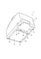
図1は、本実施形態に係るフィスカルプリンター1(電子機器)を上方から見たときの外観斜視図であり、図2は、フィスカルプリンター1を下方から見たときの外観斜視図である。
本実施形態に係るフィスカルプリンター1は、POS端末等のホストコンピューター10(図4)に接続され、ホストコンピューター10の制御の下、レシートを発行すると共に、ホストコンピューター10から入力されたフィスカル情報を含むデータを記憶する。フィスカル情報とは、商品等の販売取引に関する情報(売上に関する情報や課税額等に関する情報)であって、記憶すべき情報として予め定められた情報のことである。このフィスカル情報は、例えば、政府等の国家機関による店舗からの税金の徴収に際し、国家機関が当該店舗における取引の実態を把握するために参照する情報として利用される。本実施形態では、フィスカル情報を含むデータとして、後述する書込レシートデータ11、及び、日計売上データ12の2種類のデータが存在する。Hereinafter, embodiments of the present invention will be described with reference to the drawings.
<First Embodiment>
FIG. 1 is an external perspective view when the fiscal printer 1 (electronic device) according to the present embodiment is viewed from above, and FIG. 2 is an external perspective view when the
The
図1及び図2に示すように、フィスカルプリンター1は、プリンター本体14と、このプリンター本体14の底部15に固定された収納箱16と、を備えている。
プリンター本体14の内部には、ロール紙を搬送する搬送機構や、ロール紙に画像を記録するための記録機構等、レシートを発行するための機構、装置や、ロール紙を収納するためのロール紙収納部等が収容されている。
また、プリンター本体14は、図1に示すように、プリンター本体14の上面の前側部分を覆う前側開閉蓋17及び後側部分を覆う後側開閉蓋18を備えており、前側開閉蓋17と後側開閉蓋18との間には、幅方向に延びる記録紙排出口19が形成されている。後側開閉蓋18は、記録紙排出口19の側方に配置されているスライドボタン20を操作すると、ロック機構(不図示)が外れ、開けることが可能となる。後側開閉蓋18を開けると、ロール紙収納部が露出し、ロール紙の交換を行うことができる。また、前側開閉蓋17を開けると、インクリボンの交換等を行うことができる。As shown in FIGS. 1 and 2, the
Inside the
Further, as shown in FIG. 1, the printer
図2に示すように、収納箱16は、下面に開口部が形成された箱体の箱本体21と、この箱本体21の開口部を覆う蓋体22とを備えている。蓋体22は、箱本体21に対しビス23によって固定されている。
また、箱本体21の後方の側面には、電源アダプタや、ネットワークケーブル、プリンター本体14内部の基板に接続されたケーブルが接続されるコネクターの他、ホストコンピューター10が接続されるPCコネクター24、及び、後述するフィスカルデータ読出装置25(外部機器)が接続されるフィスカルコネクター29が設けられている。
収納箱16の内部には、管理基板26、プリンター基板27(図3及び図4参照)、及び、サブ基板28(図4参照)が収納されている。As shown in FIG. 2, the
Further, on the rear side surface of the
A
図3は、収納箱16の断面図である。
図3に示すように、収納箱16の内部において、管理基板26、及び、プリンター基板27が収納箱16に対し固定部材60によって固定されている。管理基板26には、管理側コネクター61(コネクター)が設けられ、プリンター基板27には、プリンター側コネクター62(コネクター)が設けられており、これらコネクターを介して管理基板26とプリンター基板27とが接続されている。このように、管理基板26、及び、プリンター基板27は、収納箱16に収納されているため、これら基板に物理的なアクセスを行う場合は、収納箱16の蓋体22を開状態とする必要がある。
なお、蓋体22の開状態とは、箱本体21から蓋体22が取り外され、収納箱16の内部が露出した状態のことをいい、蓋体22の閉状態とは、箱本体21の蓋体22が取り付けられ、蓋体22によって箱本体21の開口が塞がれた状態のことをいう。
なお、図示は省略したが、サブ基板28(図4)も収納箱16の内部に収納されている。FIG. 3 is a cross-sectional view of the
As shown in FIG. 3, the
The open state of the
Although not shown, the sub board 28 (FIG. 4) is also housed in the
図4は、フィスカルプリンター1の回路構成図であり、特に、収納箱16の内部に設けられた管理基板26、プリンター基板27、及び、サブ基板28の回路構成を模式的に示している。
図4に示すように、管理基板26には、メイン制御部30(制御部)と、PCコネクター24と、フィスカルコネクター29と、通信IC31と、ROM32と、SRAM33(揮発性メモリー)と、RTC38と、EJメモリー34(メモリー)と、第1メモリー制御部35と、バッファーIC36と、が実装されている。FIG. 4 is a circuit configuration diagram of the
As shown in FIG. 4, the
メイン制御部30は、フィスカルプリンター1の各部を中枢的に制御するものであり、CPUやその他の周辺回路を備えている。
PCコネクター24は、フィスカルプリンター1の通常使用時においてホストコンピューター10が接続されるコネクターである。ホストコンピューター10は、PCコネクター24を介してフィスカルプリンター1にレシートの発行に係る印刷コマンドを出力し、また、フィスカル情報を含むデータである日計売上データ12を出力する。
フィスカルコネクター29は、フィスカルデータ読出装置25(外部機器)が接続されるコネクターである。フィスカルデータ読出装置25とは、後述するEJメモリー34や、フィスカルメモリー37(メモリー)に記憶されたデータを読み出すための装置であり、例えば国家機関(政府等)に係る者等の、特別な許可を得た者だけが所持し得る。上述したホストコンピューター10はPCコネクター24に接続された状態が維持されるが、フィスカルデータ読出装置25は、ホストコンピューター10と異なり、データの読み出しが行われる際に、適宜、フィスカルコネクター29に接続される。The
The
The
通信IC31は、PCコネクター24及びフィスカルコネクター29に接続され、メイン制御部30の制御の下、ホストコンピューター10や、フィスカルデータ読出装置25との間でデータの送受信を行う。
ROM32は、メイン制御部30が各種制御を行うための制御プログラム(ファームウェア)や、制御データ等を記憶する。本実施形態では、ROM32として、EEPROM等のデータの書き換えが可能なメモリーが用いられている。ROM32には、最終書込日時データ66が記憶されるが、これについては後述する。
SRAM33は、メイン制御部30のCPUのワークエリアとして機能する揮発性のメモリーであり、各種データを一時的に記憶する。SRAM33には、EJ書込開始アドレスデータ67及びフィスカル書込開始アドレスデータ68が記憶されるがこれらについては後述する。
フィスカルプリンター1の電源がオンされ、フィスカルプリンター1に商用電源から電力が供給されている間は、SRAM33に対しても商用電源から電力が供給される。一方、フィスカルプリンター1の電源がオフされ、フィスカルプリンター1への商用電源からの電力が遮断されている間は、電池42(電源)からSRAM33に対してバックアップ用の電力が供給される。The
The
The
While the power of the
RTC38(Real-time clock:リアルタイムクロック)は、現在日時(年月日、時刻)を示すデータをメイン制御部30に出力するものであり、RTC制御部70と、RTC揮発性記憶部71と、RTC不揮発性記憶部72とを備えている。
RTC制御部70は、図示せぬ発振器が生成した基準クロックに基づいて計時動作を実行し、RTC揮発性記憶部71に記憶された現在日時データ74を更新する。RTC制御部70は、所定のデフォルト値に対し、計時した時間を加算することにより、現在日時を算出し、算出した現在日時を示すデータによって、RTC揮発性記憶部71に記憶された現在日時データ74を更新する。また、RTC制御部70は、適宜、RTC揮発性記憶部71に記憶された現在日時データ74に基づいて、現在日時を示すデータをメイン制御部30に出力する。
RTC揮発性記憶部71は、RTC38に対して電力が供給されている間のみ記憶したデータを保持する揮発性メモリーであり、RTC38に対する電力の供給が遮断された場合は、記憶したデータが消去される。ここで、RTC38に対する電力の供給が遮断されることによってRTC揮発性記憶部71に記憶された現在日時データ74が消去された後、再び、RTC38に電力が供給された場合、リセットされ初期値となった後動作を始めるので、RTC揮発性記憶部71に記憶された現在日時データ74が示す現在日時は、現実の現在日時と乖離した日時となる。
RTC不揮発性記憶部72は、RTC38に対する電力供給の有無にかかわらず、記憶したデータを保持する不揮発性メモリーである。このRTC不揮発性記憶部72は、RTC38に対する電力供給が遮断された場合であっても、リセット日時データ76(後述)を記憶するために設けられたものである。
SRAM33と同様、RTC38には、フィスカルプリンター1の電源がオンさら、フィスカルプリンター1に商用電源から電力が供給されている間は、商用電源から電力が供給される。一方、フィスカルプリンター1の電源がオフされ、フィスカルプリンター1への商用電源からの電力が遮断されている間は、電池42からバックアップ用の電力が供給される。The RTC 38 (Real-time clock) outputs data indicating the current date and time (year, month, day, time) to the
The
The RTC
The RTC
Like the
EJメモリー34は、NAND型フラッシュメモリーであり、大容量のデータを記憶可能である。EJメモリー34は、第1メモリー制御部35の制御の下、1つのアドレスに対して1度しかデータを書き込めないメモリーとして機能する。これにより、EJメモリー34に書き込まれたデータが後から編集されることが防止され、EJメモリー34に記憶されたデータ対する改ざんが防止されている。
第1メモリー制御部35は、CPUを備え、メイン制御部30の制御の下、EJメモリー34に対してデータの読み書きを行う。第1メモリー制御部35は、EJメモリー34に対して、データ、具体的には、フィスカル情報を含むデータである書込レシートデータ11(後述)を書き込む場合、当該データを暗号化した上でデータを書き込む。暗号化されたデータを復号するための機能は、上述したフィスカルデータ読出装置25等の、フィスカル情報を含むデータを正規に読み出すことが許可された限られた装置のみが有している。これにより、書込レシートデータ11の内容の漏洩の防止が図られている。
バッファーIC36は、EJメモリー34に対するデータの読み出し、書き込みの効率を向上するために設けられたバッファーを制御する。
これらEJメモリー34、第1メモリー制御部35、及び、バッファーIC36は、エポキシ樹脂によって管理基板26に封止されており、EJメモリー34が管理基板26から物理的に取り外された上で、EJメモリー34に記憶されたデータが改ざんされることが防止されている。The
The first
The
The
プリンター基板27には、プリンター制御部48が実装されている。プリンター制御部48は、CPUや各種周辺回路を備え、印刷コマンドに基づいて、上述したロール紙を搬送する搬送機構や、ロール紙に画像を記録するための画像記録機構等のレシートを発行するための機構や装置(記録部)を制御し、レシートを発行する。プリンター基板27には、プリンター側コネクター62が設けられ、管理基板26には、管理側コネクター61が設けられており、これらプリンター側コネクター62と、管理側コネクター61とが接続されることにより、管理基板26と、プリンター基板27とが接続される。
本実施形態では、レシートの発行に際し、まず、フィスカルプリンター1に接続されたホストコンピューター10が、印刷コマンドを生成し、生成した印刷コマンドをPCコネクター24を介してメイン制御部30に出力する。印刷コマンドが入力されたメイン制御部30は、入力された印刷コマンドをプリンター制御部48に出力する。A
In the present embodiment, when a receipt is issued, first, the
サブ基板28には、フィスカルメモリー37と、第2メモリー制御部50とが実装されている。
フィスカルメモリー37は、EPROMを備えるメモリーである。フィスカルメモリー37には、日計売上データ12が記憶されるが、これらについては後述する。フィスカルメモリー37は、第2メモリー制御部50の制御の下、1つのアドレスに対して1度しかデータを書き込めないメモリーとして機能する。これにより、フィスカルメモリー37に書き込まれたデータが後から編集されることが防止され、フィスカルメモリー37に記憶されたデータ対する改ざんが防止されている。
第2メモリー制御部50は、プログラム可能な論理回路を書き込んだデバイスであるCPLD(Complex programmable logic device)を備え、メイン制御部30の制御の下、フィスカルメモリー37に対してデータの読み書きを行う。第2メモリー制御部50は、フィスカルメモリー37に対して、データ、具体的には、フィスカル情報を含むデータである日計売上データ12(後述)を書き込む場合、当該データを暗号化した上でデータを書き込む。ここで暗号化されたデータを復号するための機能は、上述したフィスカルデータ読出装置25等の、フィスカル情報を含むデータを正規に読み出すことが許可された限られた装置のみが有している。これにより、日計売上データ12の内容の漏洩の防止が図られている。
これらフィスカルメモリー37、及び、第2メモリー制御部50は、エポキシ樹脂によってサブ基板28に封止されており、例えば、フィスカルメモリー37がサブ基板28から物理的に取り外された上で、フィスカルメモリー37に記憶されたデータが改ざんされることが防止されている。A
The
The second
The
次いで、EJメモリー34に記憶される書込レシートデータ11、及び、フィスカルメモリー37に記憶される日計売上データ12について説明する。上述したように、これらデータは、フィスカル情報を含むデータに該当する。
書込レシートデータ11とは、フィスカルプリンター1によって発行されるレシートに記録される情報を示すデータであって、記憶すべきデータとして予め定められているデータのことである。例えば、レシートに、顧客が購入した商品毎に、商品を示す情報や、商品の単価を示す情報、当該商品を購入した個数を示す情報、商品の購入にかかる代金を示す情報、全ての商品の総購入代金を示す情報等が記録されている場合であって、これら情報を示すデータが記憶すべきデータとして予め定められている場合、これら情報を示すデータが書込レシートデータ11に該当する。上述したように、本実施形態では、フィスカルプリンター1によってレシートを発行する場合、ホストコンピューター10によって印刷コマンドが生成され、この印刷コマンドがメイン制御部30に出力され、さらに、印刷コマンドがメイン制御部30からプリンター制御部48に出力される。その際、メイン制御部30は、印刷コマンドから、書込レシートデータ11として記憶すべき情報を抽出し、抽出したこれら情報を書込レシートデータ11として、第1メモリー制御部35を制御して、EJメモリー34に記憶する。Next, the
The
ここで、メイン制御部30は、EJメモリー34に書込レシートデータ11を書き込む際、RTC38から現在日時を示すデータを取得し、取得したデータに基づいて、書き込みを行った日時を取得し、取得した日時を示すデータ(EJ書込日時データ78)と、書込レシートデータ11とを対応づけた状態で、書込レシートデータ11を書き込む。つまり、書込レシートデータ11のそれぞれは、EJメモリー34に書き込まれた日時を示すデータであるEJ書込日時データ78と対応づけてEJメモリー34に記憶される。
このように、本実施形態では、EJ書込日時データ78と、書込レシートデータ11とを対応づけて記憶するが、これは、国によっては、法律や、規則によりそのことが義務づけられているからである。従って、フィスカルプリンター1にとって、現在日時を計時するRTC38は、必須の部材である。Here, when writing the
As described above, in the present embodiment, the EJ writing date /
日計売上データ12とは、店舗における1日ごとの総売上を示すデータのことであり、店舗の営業終了後、ホストコンピューター10がその日における総売上を計算し、計算した総売上に基づいて、日計売上データ12を生成し、生成した日計売上データ12をメイン制御部30に出力する。日計売上データ12が入力されると、メイン制御部30は、第2メモリー制御部50を制御し、フィスカルメモリー37に日計売上データ12を書き込む。
ここで、メイン制御部30は、フィスカルメモリー37に日計売上データ12を書き込む際、RTC38に現在日時を示すデータを出力させ、このデータに基づいて、書き込みを行った日時を取得し、取得した日時を示すデータ(フィスカル書込日時データ79)と、日計売上データ12とを対応づけた状態で、フィスカルメモリー37に日計売上データ12を書き込む。つまり、日計売上データ12のそれぞれは、フィスカルメモリー37に書き込まれた日時を示すデータであるフィスカル書込日時データ79と対応づけてフィスカルメモリー37に記憶される。
このように、本実施形態では、フィスカル書込日時データ79と、日計売上データ12とを対応づけて記憶するが、これは、国によっては、法律や、規則によりそのことが義務づけられているからである。従って、フィスカルプリンター1にとって、現在日時を計時するRTC38は、必須の部材である。The
Here, when writing the
As described above, in the present embodiment, the fiscal writing date /
次いで、最終書込日時データ66ついて説明する。
最終書込日時データ66とは、メイン制御部30が第1メモリー制御部35又は第2メモリー制御部50を制御して、EJメモリー34又はフィスカルメモリー37に対してデータを書き込んだ最後の日時を示すデータである。メイン制御部30は、これらメモリーにデータを書き込む度に、RTC38から入力された現在日時を示すデータに基づいて、最終書込日時データ66を更新する。
本実施形態では、メイン制御部30は、EJメモリー34や、フィスカルメモリー37に対してデータを書き込む際、以下の動作を実行する。
すなわち、メイン制御部30は、データを書き込む前に、ROM32に記憶された最終書込日時データ66を取得し、取得した最終書込日時データ66が示す日時と、RTC38から入力されるデータが示す日時とを比較する。ここで、RTC38から入力されたデータが正常である場合は、最終書込日時データ66が示す日時は、RTC38から入力されたデータが示す日時よりも時間的に前のはずである。
そして、最終書込日時データ66が示す日時が、RTC38から入力されたデータが示す日時よりも時間的に前である場合、メイン制御部30は、引き続きデータの書き込み処理を実行する。
一方、最終書込日時データ66が示す日時が、RTC38から入力されたデータが示す日時よりも時間的に後である場合、メイン制御部30は、RTCエラーが発生したものとして、以後、フィスカルプリンター1の作動を停止する。
なお、最終書込日時データ66が示す日時が、RTC38から入力されたデータが示す日時よりも時間的に後となるような場合には、RTC38に何らかの異常が発生した場合の他、後述するように、蓋体22が開状態とされ、RTC38のRTC揮発性記憶部71に記憶された現在日時データ74がリセットされた場合がある。Next, the final writing date /
The last write date /
In the present embodiment, the
That is, the
When the date / time indicated by the last write date /
On the other hand, if the date / time indicated by the last write date /
If the date / time indicated by the last write date /
次いで、SRAM33に記憶されたEJ書込開始アドレスデータ67及びフィスカル書込開始アドレスデータ68について説明する。
EJ書込開始アドレスデータ67とは、EJ書込開始アドレスを示すデータである。EJ書込開始アドレスとは、EJメモリー34にデータを書き込む際に、EJメモリー34のメモリー領域において書き込みが開始されるアドレスのことである。本実施形態では、EJメモリー34に対してデータの書き込みが行われる度に、第1メモリー制御部35が、次回、EJメモリー34に対してデータを書き込む際のEJ書込開始アドレスを取得し、取得した書込開始アドレスを示すデータをメイン制御部30に出力する。メイン制御部30は、このEJ書込開始アドレスを示すデータを、SRAM33に記憶し、次回、書込レシートデータ11をEJメモリー34に書き込む場合は、SRAM33からEJ書込開始アドレスデータ67を取得し、取得したEJ書込開始アドレスデータ67が示すアドレスにデータを書き込む旨の書込要求コマンドを出力する。
上述したように、EJ書込開始アドレスデータ67は、書込要求コマンドの出力に際し、必要となるデータであり、SRAM33に記憶されたEJ書込開始アドレスデータ67が消去された場合、メイン制御部30は、正常な書込要求コマンドを生成できない。このため、本実施形態では、メイン制御部30は、フィスカルプリンター1の電源がオンされた際、SRAM33を参照し、SRAM33に記憶されたEJ書込開始アドレスデータ67が消去されている場合には、SRAMエラーとして、以後のフィスカルプリンター1の作動を停止する。SRAM33に記憶されたEJ書込開始アドレスデータ67が消去される具体例については、後述の第3実施形態、及び、第4実施形態において詳述する。
フィスカル書込開始アドレスデータ68とは、フィスカル書込開始アドレスを示すデータであり、フィスカル書込開始アドレスとは、フィスカルメモリー37にデータを書き込む際に、フィスカルメモリー37のメモリー領域において書き込みが開始されるアドレスのことである。フィスカル書込開始アドレスの利用態様は、EJ書込開始アドレスの利用態様と同様であるため、その説明を省略する。Next, the EJ write
The EJ write
As described above, the EJ write
The fiscal write
ところで、収納箱16には、管理基板26やサブ基板28が収納されており、管理基板26には、フィスカル情報を含むデータである書込レシートデータ11が記憶されたEJメモリー34が実装され、サブ基板28には、同じくフィスカル情報を含むデータである日計売上データ12が記憶されたフィスカルメモリー37が実装されている。
従って、不正の目的を持った者が、EJメモリー34に記憶された書込レシートデータ11や、フィスカルメモリー37に記憶された日計売上データ12を改ざんしようとする場合、フィスカルプリンター1の電源がオフされているときに、プリンター本体14から収納箱16を取り外し、さらに、収納箱16の蓋体22を開状態として、収納箱16に収納された各基板を露出した上で、これらメモリーに対して改ざんに係る処理を行うと考えられる。
これを踏まえ、収納箱16の蓋体22が開状態となった場合、以後、フィスカルプリンター1が正常に動作しない構成とすれば、改ざんがあった可能性があることを確実に検出できると共に、改ざんの抑止力ともなり得る。By the way, a
Therefore, when a person with an unauthorized purpose tries to falsify the written
Based on this, when the
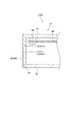
図5は、収納箱16の断面図に、電池42とRTC38との間に設けられ、電池42からRTC38に電力を供給するための電力供給ライン80(電力供給路)を模式的に示した図である。
図5に示すように、電力供給ライン80は、箱本体21の側面に沿って延在しており、一部に蓋体22の内部に突出した突出部81が形成されている。突出部81は、蓋体22に対して強固に固定されており、蓋体22が開状態となった場合、蓋体22の箱本体21からの分離に伴い、突出部81が電力供給ライン80から物理的に分離し、これにより電力供給ライン80が切断される構成となっている。
このような形状の下、蓋体22が閉状態の場合は、電力供給ライン80を介して電池42とRTC38とが電気的に接続され、電池42からRTC38への電力の供給が正常に行われる。
一方、蓋体22が開状態となった場合、突出部81において、電力供給ライン80が機械的に遮断され、以後、電池42からRTC38への電力の供給が遮断される。ここで、フィスカルプリンター1の電源がオフであったり、また、収納箱16がプリンター本体から取り外されたりすることによって、電池42からRTC38へ電力が供給されている場合において、蓋体22が開状態とされることにより、電池42からRTC38への電力の供給が遮断された場合、RTC38への一切の電力供給が遮断され、これにより、RTC揮発性記憶部71に記憶された現在日時データ74が消去されると共に、以後のRTC38の作動が停止される。FIG. 5 is a diagram schematically showing a power supply line 80 (power supply path) provided between the
As shown in FIG. 5, the
Under such a shape, when the
On the other hand, when the
このように、本実施形態では、蓋体22が開状態となった場合、電力供給ライン80が遮断されることにより、RTC38への電力の供給が遮断され、RTC揮発性記憶部71に記憶された現在日時データ74が消去される。
ここで、現在日時データ74が消去された後に、再び、蓋体22が閉状態とされて収納箱16がプリンター本体14に正常に取り付けられると共に、収納箱16に収納された各基板と、レシートを発行するための機構や装置等の電気的な接続が正常に行われた上で、フィスカルプリンター1の電源がオンされた場合におけるフィスカルプリンター1の動作について説明する。この場合、RTC38には、商用電源から電力が供給される。また、RTC38はリセットされ初期値から動作を開始する。
上述したように、本実施形態では、EJメモリー34やフィスカルメモリー37に対してデータを書き込む場合、メイン制御部30は、ROM32に記憶された最終書込日時データ66が示す日時と、RTC38から入力されたデータが示す日時とを比較し、ROM32に記憶された最終書込日時データ66が示す日時が、RTC38から入力されたデータが示す日時よりも時間的に後である場合、RTCエラーが発生したものとして、以後、フィスカルプリンター1の作動を停止する。
これを踏まえ、蓋体22が開状態となったことに起因して、一旦、RTC38への電力の供給が遮断され、RTC揮発性記憶部71に記憶された現在日時データ74が消去された場合、メイン制御部30によるデータの書き込みに際して行われる日時の比較において、ROM32に記憶された最終書込日時データ66が示す日時が、RTC38から入力されたデータが示す日時よりも時間的に後と判別され、メイン制御部30は、以後、フィスカルプリンター1の作動を停止する。As described above, in the present embodiment, when the
Here, after the current date /
As described above, in this embodiment, when data is written to the
Based on this, when the
このように、本実施形態では、プリンター本体14から収納箱16が取り外された上で、蓋体22が開状態となった場合、換言すれば、EJメモリー34やフィスカルメモリー37に記憶されたデータに対し改ざんの目的を持ったアクセスが可能な状態となった場合、フィスカルプリンター1の動作が停止する。これにより、改ざんの目的を持って蓋体22を開状態とすることを牽制でき、かつ、蓋体22が開状態とされた場合、確実にそのことを検出できる。つまり、フィスカルプリンター1は、改ざんに対して有効な処理を実行する。レシートなどの印刷ができなくする。 Thus, in the present embodiment, when the
以上説明したように、本実施形態に係るフィスカルプリンター1では、蓋体22が開状態となると、電力供給ライン80が機械的に遮断されて、RTC38に対する電力の供給が遮断される。
これによれば、蓋体22が開状態とされた場合、RTC38に対する電力の供給が遮断され、RTC38が計時する現在日時が消去される。このため、蓋体22が開状態とされた以後は、RTC38からメイン制御部30に対し、実際の現在日時と乖離した日時を示すデータが出力される。従って、RTC38から入力されるデータが示す日時が、実際の日時と乖離していることを利用して、メイン制御部30は、蓋体22が開状態となった以後のフィスカルプリンター1の作動を停止する等の、蓋体22を開状態とした上で行われる改ざんに対して有効な処理を実行できる。As described above, in the
According to this, when the
<第2実施形態>
次いで、第2実施形態に係るフィスカルプリンター1bについて図5を援用して説明する。
図5において、電池42からSRAM33へ電力を供給するための電力供給ライン84(電力供給路)が、上述した第1実施形態で説明した、電池42からRTC38へ電力を供給するための電力供給ライン80に該当する。
上述した第1実施形態では、蓋体22が開状態とされた場合、電池42からRTC38へ電力を供給するための電力供給ライン80が機械的に遮断されていたが、本実施形態では、蓋体22が開状態とされた場合、電池42からSRAM33へ電力を供給するための電力供給ライン84が機械的に遮断され、これにより、電池42からSRAM33への電力の供給が遮断される。すなわち、蓋体22が閉状態の場合は、電力供給ライン84を介して電池42とSRAM33とが電気的に接続され、電池42からSRAM33への電力の供給が正常に行われる。一方、蓋体22が開状態となった場合、電力供給ライン84の突出部81が機械的に遮断され、以後、電池42からSRAM33への電力の供給が遮断される。ここで、フィスカルプリンター1の電源がオフであったり、また、収納箱16がプリンター本体14から取り外されたりすることによって、電池42からSRAM33へ電力が供給されている場合において、蓋体22が開状態とされることにより、電池42からSRAM33への電力の供給が遮断された場合、SRAM33への一切の電力供給が遮断され、これにより、揮発性メモリーたるSRAM33に記憶されたデータが消去される。消去されるデータには、EJ書込開始アドレスデータ67、及び、フィスカル書込開始アドレスデータ68が含まれている。Second Embodiment
Next, the
In FIG. 5, the power supply line 84 (power supply path) for supplying power from the
In the first embodiment described above, when the
このように、本実施形態では、蓋体22が開状態となった場合、SRAM33に記憶されたEJ書込開始アドレスデータ67やフィスカル書込開始アドレスデータ68が消去されるが、上述したように、これらデータが消去された場合、フィスカルプリンター1bの電源がオンされた際に、SRAMエラーとして、以後のフィスカルプリンター1cの作動が停止する。これにより、第1実施形態で説明した効果と同様の効果を奏することができる。 As described above, in this embodiment, when the
以上説明したように、本実施形態に係るフィスカルプリンター1bは、蓋体22が開状態となると、電池42からSRAM33へ電力を供給するための電力供給ライン84が機械的に遮断されて、揮発性メモリーたるSRAM33に対する電力の供給が遮断される。
この構成によれば、収納箱16の蓋体22が開状態とされた場合、SRAM33に対する電力の供給が遮断され、SRAM33が記憶するEJ書込開始アドレスデータ67や、フィスカル書込開始アドレスデータ68等のデータが消去される。このため、収納箱16の蓋体22が開状態とされた以後は、SRAM33に記憶されたデータを利用したメイン制御部30によるEJメモリー34やフィスカルメモリー37への正常なアクセスが実行できなくなり、これに基づいて、メイン制御部30は、蓋体22が開状態となった以後は、フィスカルプリンター1bの作動を停止する等の、蓋体22を開状態とした上で行われる改ざんに対して有効な処理を実行できる。As described above, in the
According to this configuration, when the
次いで、第3実施形態に係るフィスカルプリンター1cついて説明する。
以下の説明において、第1実施形態で説明した構成要素と同一の構成要素については、同一の符号を付し、その説明を省略する。
上述した第1実施形態では、蓋体22が開状態となった場合、電池42とRTC38とを結ぶ電力供給ライン80が機械的に遮断されることによりRTC38への電力の供給が遮断され、これに基づいて蓋体22が開状態となった以後のフィスカルプリンター1の作動が停止されていたが、本実施形態では、収納箱16から管理基板26が取り外された場合、電池42とRTC38とを結ぶ電力供給ライン及び電池42とSRAM33とを結ぶ電力供給ラインが機械的に遮断されることによりRTC38への電力の供給及びSRAM33への電力の供給が遮断され、これに基づいて収納箱16から管理基板26が取り外された以後のフィスカルプリンター1の作動が停止する。
ここで、通常使用時、収納箱16から管理基板26が取り外されることはなく、収納箱16から管理基板26が取り外された場合、不正の目的を持ってEJメモリー34に記憶された書込レシートデータ11等を改ざんしようとする者が、作業の容易性の向上等の目的で収納箱16から管理基板26を取り外したことが考えられる。従って、収納箱16から管理基板26が取り外された場合、フィスカルプリンター1の作動を停止するようにすれば、上述のような改ざんを牽制でき、かつ、収納箱16から管理基板26が取り外された場合、確実にそのことを検出できる。つまり、フィスカルプリンター1は、改ざんに対して有効な処理を実行できる。Next, the
In the following description, the same components as those described in the first embodiment are denoted by the same reference numerals, and the description thereof is omitted.
In the first embodiment described above, when the
Here, during normal use, the
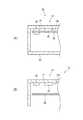
図6は、収納箱16の断面図を示し、特に、(A)は管理基板26が収納箱16に対して取り付けられている状態を示しており、(B)は管理基板26が収納箱16のから取り外された状態を示している。
図6に示すように、本実施形態では、収納箱16の内部において、収納箱16の天面16aに対して、電池42が、接着等の手段により固定されている。
図6(A)に示すように、管理基板26が固定部材60を介して収納箱16に固定された状態の場合、電池42の端子が、電池42とRTC38とを接続する電力供給ライン(不図示)、及び、電池42とSRAM33とを接続する電力供給ライン(不図示)に接続され、電池42からRTC38及びSRAM33に対し正常に電力が供給される。
一方、図6(B)に示すように、管理基板26と固定部材60との接続が解除され、収納箱16から管理基板26が取り外された状態の場合、電池42と、電池42とRTC38とを接続する電力供給ライン(不図示)との接続が機械的に遮断される(電力供給路が機械的に遮断される)と共に、電池42と、電池42とSRAM33とを接続する電力供給ライン(不図示)との接続が機械的に遮断され(電力供給路が機械的に遮断され)、電池42からRTC38及びSRAM33に対する電力の供給が遮断される。
電池42からRTC38への電力の供給が遮断された場合、上述したように、RTC38のRTC揮発性記憶部71に記憶された現在日時データ74が消去され、これに基づいて、フィスカルプリンター1cの電源がオンとなった後のフィスカルプリンター1cの作動が停止する。同時に、電池42からSRAM33への電力の供給が遮断された場合、上述したように、SRAM33に記憶されたEJ書込開始アドレスデータ67やフィスカル書込開始アドレスデータ68が消去され、これに基づいて、フィスカルプリンター1cの電源がオンとなった後のフィスカルプリンター1cの作動が停止する。これにより、第1実施形態で説明した効果と同様の効果を奏することができる。
なお、本実施形態では、管理基板26が収納箱16から取り外された場合、電池42とRTC38とを接続する電力供給ライン(不図示)との接続が機械的に遮断されると共に、電池42と、電池42とSRAM33とを接続する電力供給ライン(不図示)との接続が機械的に遮断される構成であったが、管理基板26が収納箱16から取り外された場合、2つの電力供給ライン80のうちいずれかの電力供給ライン80と電池42との接続が遮断されるようにしてもよい。この構成であっても、電源がオンとなった後のフィスカルプリンター1の作動を停止でき、上述した効果と同様の効果を奏することができる。FIG. 6 shows a cross-sectional view of the
As shown in FIG. 6, in the present embodiment, the
As shown in FIG. 6A, when the
On the other hand, as shown in FIG. 6B, when the connection between the
When the supply of power from the
In the present embodiment, when the
以上説明したように、本実施形態に係るフィスカルプリンター1cでは、収納箱16から管理基板26が取り外されると、電池42とRTC38とを結ぶ電力供給ラインが機械的に遮断されて、RTC38に対する電力の供給が遮断される。
これによれば、収納箱16から管理基板26が取り外された場合、RTC38に対する電力の供給が遮断され、RTC38が計時する現在日時が消去される。このため、収納箱16から管理基板26が取り外された以後は、RTC38からメイン制御部30に対し、実際の現在日時と乖離した日時を示すデータが出力される。従って、RTC38から入力されるデータが示す日時が、実際の日時と乖離していることを利用して、メイン制御部30は、収納箱16から管理基板26が取り外された後はフィスカルプリンター1cの作動を停止する等の、収納箱16から管理基板26が取り外された上で行われる改ざんに対して有効な処理を実行できる。As described above, in the
According to this, when the
また、本実施形態に係るフィスカルプリンター1cでは、収納箱16から管理基板26が取り外されると、電池42とSRAM33とを結ぶ電力供給ラインが機械的に遮断されて、SRAM33に対する電力の供給が遮断される。
これによれば、収納箱16から管理基板26が取り外された場合、SRAM33に対する電力の供給が遮断され、SRAM33が記憶するEJ書込開始アドレスデータ67、及び、フィスカル書込開始アドレスデータ68が消去される。このため、収納箱16から管理基板26が取り外された以後は、SRAM33に記憶されたEJ書込開始アドレスデータ67、及び、フィスカル書込開始アドレスデータ68を利用したメイン制御部30によるEJメモリー34等への正常なアクセスが実行できなくなり、これに基づいて、メイン制御部30は、収納箱16から管理基板26が取り外された後はフィスカルプリンター1cの作動を停止する等の、収納箱16から管理基板26が取り外された上で行われる改ざんに対して有効な処理を実行できる。In the
According to this, when the
<第4実施形態>
次いで、第4実施形態に係るフィスカルプリンター1dついて説明する。
以下の説明において、第1実施形態で説明した構成要素と同一の構成要素については、同一の符号を付し、その説明を省略する。
上述した第1実施形態では、蓋体22が開状態となった場合、電池42とRTC38とを結ぶ電力供給ライン80が機械的に遮断されることによりRTC38への電力の供給が遮断され、これに基づいて蓋体22が開状態となった以後のフィスカルプリンター1の作動が停止されていたが、本実施形態では、管理基板26とプリンター基板27との接続が解除された場合、電池42とRTC38とを結ぶ電力供給ライン86(電力供給路)が機械的に遮断されることによりRTC38への電力の供給が遮断され、これに基づいて管理基板26とプリンター基板27との接続が解除された以後のフィスカルプリンター1dの作動が停止される。
ここで、管理基板26及びプリンター基板27は、基板同士が接続されている状態でのみ、フィスカルプリンター1の全体の制御が可能である。従って、通常動作時において管理基板26とプリンター基板27との接続が解除されることはなく、これら基板の接続が解除された場合、改ざんの目的を持った者が、作業の容易性の向上等の何らかの目的を持ってこれら基板の接続を解除したものと考えられる。
これを踏まえ、本実施形態によれば、管理基板26とプリンター基板27との接続が解除された場合、フィスカルプリンター1dの作動が停止される。これにより、他人による改ざんを牽制でき、かつ、管理基板26とプリンター基板27との接続が解除された場合、確実にそのことを検出できる。つまり、フィスカルプリンター1dは、改ざんに対して有効な処理を実行する。<Fourth embodiment>
Next, a
In the following description, the same components as those described in the first embodiment are denoted by the same reference numerals, and the description thereof is omitted.
In the first embodiment described above, when the
Here, the
Based on this, according to the present embodiment, when the connection between the
図7(A)は、本実施形態における管理基板26及びプリンター基板27の構成を模式的に示す図である。
図7(A)に示すように、一端86aが電池42に接続された電力供給ライン86は、管理側コネクター61及びプリンター側コネクター62を介して、プリンター基板27に延出した後、折り返し、再び、プリンター側コネクター62及び管理側コネクター61を介して管理基板26を延出し、他端86bがRTC38に接続されている。このような構成の下、管理側コネクター61とプリンター側コネクター62との接続が解除されることにより、管理基板26とプリンター基板27との接続が解除された場合、管理側コネクター61とプリンター側コネクター62との接続部分において、電力供給ライン86が切断され、これにより電力供給ライン86が機械的に遮断され、RTC38に対する電力の供給が遮断される。
管理基板26とプリンター基板27との接続が解除されることにより、電池42からRTC38への電力の供給が遮断された場合、上述したように、RTC38のRTC揮発性記憶部71に記憶された現在日時データ74が消去され、これに基づいて、フィスカルプリンター1dの電源がオンとなった後のフィスカルプリンター1dの作動が停止する。これは、上述した第1実施形態で説明したように、改ざんに対して有効な処理である。FIG. 7A is a diagram schematically illustrating the configuration of the
As shown in FIG. 7A, the
When the supply of power from the
以上説明したように、本実施形態では、管理基板26とプリンター基板27との接続が解除されると、電力供給ライン86が機械的に遮断されて、RTC38に対する電力の供給が遮断される。
これによれば、管理基板26とプリンター基板27との接続が解除された場合、RTC38に対する電力の供給が遮断され、RTC38が計時する現在日時が消去される。このため、管理基板26とプリンター基板27との接続が解除された以後は、RTC38からメイン制御部30に対し、実際の現在日時と乖離した日時を示すデータが出力される。従って、RTC38から入力されるデータが示す日時が、実際の日時と乖離していることを利用して、メイン制御部30は、管理基板26とプリンター基板27との接続が解除された後は、フィスカルプリンター1dの作動を停止する等の、管理基板26とプリンター基板27との接続が解除された上で行われる改ざんに対して有効な処理を実行できる。As described above, in this embodiment, when the connection between the
According to this, when the connection between the
<第5実施形態>
次いで、第5実施形態に係るフィスカルプリンター1eついて説明する。
以下の説明において、第1実施形態で説明した構成要素と同一の構成要素については、同一の符号を付し、その説明を省略する。
上述した第1実施形態では、蓋体22が開状態となった場合、電池42とRTC38とを結ぶ電力供給ライン80が機械的に遮断されることによりRTC38への電力の供給が遮断され、これに基づいて蓋体22が開状態となった以後のフィスカルプリンター1の作動が停止されていたが、本実施形態では、管理基板26とプリンター基板27との接続が解除された場合、電池42とSRAM33とを結ぶ電力供給ライン87(電力供給路)が機械的に遮断されることによりSRAM33への電力の供給が遮断され、これに基づいて管理基板26とプリンター基板27との接続が解除された以後のフィスカルプリンター1dの作動が停止される。
ここで、管理基板26及びプリンター基板27は、基板同士が接続されている状態でのみ、フィスカルプリンター1の全体の制御が可能である。従って、通常動作時において管理基板26とプリンター基板27との接続が解除されることはなく、これら基板の接続が解除された場合、改ざんの目的を持った者が、作業の容易性の向上等の何らかの目的を持ってこれら基板の接続を解除したものと考えられる。
これを踏まえ、本実施形態によれば、管理基板26とプリンター基板27との接続が解除された場合、フィスカルプリンター1dの作動が停止される。これにより、他人による改ざんを牽制でき、かつ、管理基板26とプリンター基板27との接続が解除された場合、確実にそのことを検出できる。つまり、フィスカルプリンター1eは、改ざんに対して有効な処理を実行する。<Fifth Embodiment>
Next, a fiscal printer 1e according to a fifth embodiment will be described.
In the following description, the same components as those described in the first embodiment are denoted by the same reference numerals, and the description thereof is omitted.
In the first embodiment described above, when the
Here, the
Based on this, according to the present embodiment, when the connection between the
図7(B)は、本実施形態における管理基板26及びプリンター基板27の構成を模式的に示す図である。
図7(B)に示すように、一端87aが電池42に接続された電力供給ライン87は、管理側コネクター61及びプリンター側コネクター62を介して、プリンター基板27に延出した後、折り返し、再び、プリンター側コネクター62及び管理側コネクター61を介して管理基板26を延出し、他端87bがSRAM33に接続されている。このような構成の下、管理側コネクター61とプリンター側コネクター62との接続が解除されることにより管理基板26とプリンター基板27との接続が解除された場合、管理側コネクター61とプリンター側コネクター62との接続部分において、電力供給ライン87が切断され、これにより電力供給ライン87が機械的に遮断され、SRAM33に対する電力の供給が遮断される。
管理基板26とプリンター基板27との接続が解除されることにより、電池42からSRAM33への電力の供給が遮断された場合、上述したように、SRAM33が記憶するEJ書込開始アドレスデータ67やフィスカル書込開始アドレスデータ68が消去され、これにより、電源がオンされた後のフィスカルプリンター1eの作動が停止される。これは、上述した第1実施形態で説明したように、改ざんに対して有効な処理である。FIG. 7B is a diagram schematically illustrating the configuration of the
As shown in FIG. 7B, the
When the power supply from the
以上説明したように、本実施形態では、管理基板26とプリンター基板27との接続が解除されると、電力供給ライン87が機械的に遮断されて、SRAM33に対する電力の供給が遮断される。
これによれば、管理基板26とプリンター基板27との接続が解除された場合、SRAM33に対する電力の供給が遮断され、SRAM33に対する電力の供給が遮断され、SRAM33が記憶するEJ書込開始アドレスデータ67、及び、フィスカル書込開始アドレスデータ68が消去される。このため、管理基板26とプリンター基板27との接続が解除された以後は、SRAM33に記憶されたEJ書込開始アドレスデータ67を利用したメイン制御部30によるEJメモリー34等への正常なアクセスが実行できなくなり、これに基づいて、メイン制御部30は、管理基板26とプリンター基板27との接続が解除された後はフィスカルプリンター1eの作動を停止する等の、管理基板26とプリンター基板27との接続が解除された上での行われる改ざんに対して有効な処理を実行できる。この場合、エラーや異常である旨を表示や通知したりすることもできる。また、改ざんの形跡も残る。As described above, in this embodiment, when the connection between the
According to this, when the connection between the
なお、上述した実施の形態は、あくまでも本発明の一態様を示すものであり、本発明の範囲内で任意に変形および応用が可能である。
上述した第1実施形態では、電力供給ライン80の形状の一例を挙げて発明を説明したが、電力供給ライン80の形状はこれに限らず、蓋体22が開状態となった場合に、電力供給ライン80が機械的に遮断され、RTC38への電力の供給が遮断される構成であればよい。このことは、第2実施形態における電力供給ライン84についても同様である。
また、上述した第3実施形態では、電池42や、管理基板26、電力供給ライン80等の各種部材の位置関係について、一例を挙げて説明したが、これらの位置関係や形状、構成等はこれに限らず、収納箱16から管理基板26が取り外された際に、RTC38やSRAM33への電池42からの電力の供給が遮断される構成であればよい。
また、上述した第4実施形態では、電力供給ライン86の形状の一例を挙げて発明を説明したが、電力供給ライン86の形状はこれに限らず、管理基板26とプリンター基板27との接続が解除された場合に、電力供給ライン86が機械的に遮断され、RTC38への電力の供給が遮断される構成であればよい。このことは、第5実施形態における電力供給ライン87についても同様である。The above-described embodiment is merely an aspect of the present invention, and can be arbitrarily modified and applied within the scope of the present invention.
In the first embodiment described above, the invention has been described by taking an example of the shape of the
In the above-described third embodiment, the positional relationship among various members such as the
In the above-described fourth embodiment, the invention has been described by taking an example of the shape of the
1、1b、1c、1d、1e…フィスカルプリンター、11…書込レシートデータ(フィスカル情報を含むデータ)、12…日計売上データ(フィスカル情報を含むデータ)、16…収納箱、21…箱本体、22…蓋体、26…管理基板、27…プリンター基板、30…メイン制御部(制御部)、33…SRAM(揮発性メモリー)、34…EJメモリー(メモリー)、37…フィスカルメモリー(メモリー)、38…RTC(リアルタイムクロック)、42…電池(電源)、61…管理側コネクター(コネクター)、62…プリンター側コネクター(コネクター)、80、84,86,87…電力供給ライン(電力供給路)。 DESCRIPTION OF
Claims (8)
Translated fromJapanese箱本体と蓋体とを有し、前記管理基板を収納する収納箱と、を備え、
前記蓋体が閉状態のとき、前記電力供給路が形成されて、前記リアルタイムクロックに電力の供給がされ、
前記蓋体が開状態となると、前記電力供給路が機械的に遮断されて、前記リアルタイムクロックに対する電力の供給が遮断されることを特徴とする電子機器。A control unit, a real-time clock that outputs data indicating the current date and time to the control unit, and a memory that stores fiscal data that is data including data and fiscal information under the control of the control unit; A management board having a power supply for supplying power to the real-time clock via a power supply path;
A storage box having a box body and a lid and storing the management board;
When the lid is in a closed state, the power supply path is formed, and power is supplied to the real-time clock,
When the lid is in an open state, the power supply path is mechanically cut off, and the supply of power to the real-time clock is cut off.
箱本体と蓋体とを有し、前記管理基板を収納する収納箱と、を備え、
前記蓋体が閉状態のとき、前記電力供給路が形成されて、前記揮発性メモリーに電力の供給がされ、
前記蓋体が開状態となると、前記電力供給路が機械的に遮断されて、前記揮発性メモリーに対する電力の供給が遮断されることを特徴とする電子機器。A control unit, a real-time clock that outputs data indicating the current date and time to the control unit, and a memory that stores fiscal data that is data including data and fiscal information under the control of the control unit; A management board having a volatile memory for storing data for access to the memory by the control unit, and a power supply for supplying power to the volatile memory via a power supply path;
A storage box having a box body and a lid and storing the management board;
When the lid is closed, the power supply path is formed and power is supplied to the volatile memory,
When the lid is in an open state, the power supply path is mechanically cut off, and the supply of power to the volatile memory is cut off.
この管理基板が収納されて取り付けられる収納箱と、を備え、
前記収納箱に前記管理基板が取り付けられているとき、前記電力供給路が形成されて、前記リアルタイムクロックに電力の供給がされ、
前記収納箱から前記管理基板が取り外されると、前記電力供給路が機械的に遮断されて、前記リアルタイムクロックに対する電力の供給が遮断されることを特徴とする電子機器。A control unit, a real-time clock that outputs data indicating the current date and time to the control unit, and a memory that stores fiscal data that is data including data and fiscal information under the control of the control unit; A management board having a power supply for supplying power to the real-time clock via a power supply path;
A storage box in which the management board is stored and attached;
When the management board is attached to the storage box, the power supply path is formed, and power is supplied to the real-time clock,
When the management board is removed from the storage box, the power supply path is mechanically cut off, and power supply to the real-time clock is cut off.
この管理基板が収納されて取り付けられる収納箱と、を備え、
前記収納箱に前記管理基板が取り付けられているとき、前記電力供給路が形成されて、前記揮発性メモリーに電力の供給がされ、
前記収納箱から前記管理基板が取り外されると、前記電力供給路が機械的に遮断されて、前記揮発性メモリーに対する電力の供給が遮断されることを特徴とする電子機器。A control unit, a real-time clock that outputs data indicating the current date and time to the control unit, and a memory that stores fiscal data that is data including data and fiscal information under the control of the control unit; A management board having a volatile memory for storing data for access to the memory by the control unit, and a power supply for supplying power to the volatile memory via a power supply path;
A storage box in which the management board is stored and attached;
When the management board is attached to the storage box, the power supply path is formed, and power is supplied to the volatile memory,
When the management board is removed from the storage box, the power supply path is mechanically cut off, and power supply to the volatile memory is cut off.
プリンターと、
この管理基板に接続された前記プリンター用のプリンター基板と、を備え、
前記管理基板と前記プリンター基板とが接続されているとき、前記電力供給路が形成されて、前記リアルタイムクロックに電力の供給がされ、
前記管理基板と前記プリンター基板との接続が解除されると、前記電力供給路が機械的に遮断されて、前記リアルタイムクロックに対する電力の供給が遮断されることを特徴とする電子機器。A control unit, a real-time clock that outputs data indicating the current date and time to the control unit, and a memory that stores fiscal data that is data including data and fiscal information under the control of the control unit; A management board having a volatile memory for storing data for access to the memory by the control unit, and a power supply for supplying power to the real-time clock via a power supply path;
A printer,
A printer board for the printer connected to the management board, and
When the management board and the printer board are connected, the power supply path is formed and power is supplied to the real-time clock,
When the connection between the management board and the printer board is released, the power supply path is mechanically cut off, and the supply of power to the real-time clock is cut off.
プリンターと、
この管理基板に接続された前記プリンター用のプリンター基板と、を備え、
前記管理基板と前記プリンター基板とが接続されているとき、前記電力供給路が形成されて、前記揮発性メモリーに電力の供給がされ、
前記管理基板と前記プリンター基板との接続が解除されると、前記電力供給路が機械的に遮断されて、前記揮発性メモリーに対する電力の供給が遮断されることを特徴とする電子機器。A control unit, a real-time clock that outputs data indicating the current date and time to the control unit, and a memory that stores fiscal data that is data including data and fiscal information under the control of the control unit; A management board having a volatile memory for storing data for access to the memory by the control unit, and a power supply for supplying power to the volatile memory via a power supply path;
A printer,
A printer board for the printer connected to the management board, and
When the management board and the printer board are connected, the power supply path is formed and power is supplied to the volatile memory,
When the connection between the management board and the printer board is released, the power supply path is mechanically cut off, and the supply of power to the volatile memory is cut off.
前記メモリーを搭載する管理基板を収納する収納箱の蓋体が閉状態のとき、前記リアルタイムクロックおよび揮発性メモリーへの電力供給路を形成して電力を供給し、
蓋体が開状態のとき、前記リアルタイムクロックまたは前記揮発性メモリーへの電力供給路を機械的に遮断して、電力の供給を遮断することを特徴とする電子機器の制御方法。The data indicating the current date and time measured by the real-time clock and the fiscal data, which is data including fiscal information, are stored in the memory.
When the lid of the storage box that stores the management board on which the memory is mounted is closed, the power is supplied by forming a power supply path to the real-time clock and the volatile memory,
A method for controlling an electronic device, wherein when the lid is in an open state, the power supply path to the real time clock or the volatile memory is mechanically cut off to cut off the supply of power.
前記メモリーを搭載する管理基板が収納箱に取り付けられているとき、前記リアルタイムクロックおよび揮発性メモリーへの電力供給路を形成して電力を供給し、
前記管理基板が前記収納箱から取り外されているとき、前記リアルタイムクロックまたは前記揮発性メモリーへの電力供給路を機械的に遮断して、電力の供給を遮断することを特徴とする電子機器の制御方法。The data indicating the current date and time measured by the real-time clock and the fiscal data, which is data including fiscal information, are stored in the memory.
When a management board on which the memory is mounted is attached to a storage box, power is supplied by forming a power supply path to the real-time clock and the volatile memory,
When the management board is removed from the storage box, the power supply path to the real time clock or the volatile memory is mechanically cut off to cut off the supply of electric power, Method.
Priority Applications (6)
| Application Number | Priority Date | Filing Date | Title |
|---|---|---|---|
| JP2009287306AJP2011126149A (en) | 2009-12-18 | 2009-12-18 | Electronic device and method of controlling electronic device |
| BRPI1005607-6ABRPI1005607B1 (en) | 2009-12-17 | 2010-12-13 | electronic device and method to control electronic device |
| RU2010151786/08ARU2459265C1 (en) | 2009-12-17 | 2010-12-16 | Electronic device and method to control electronic device |
| CN2010105980489ACN102103776B (en) | 2009-12-17 | 2010-12-16 | Electronic device and control method for electronic device |
| CN201310150121XACN103258391A (en) | 2009-12-17 | 2010-12-16 | Electronic apparatus and method of controlling electronic apparatus |
| US12/972,020US8661270B2 (en) | 2009-12-17 | 2010-12-17 | Electronic apparatus and method of controlling electronic apparatus |
Applications Claiming Priority (1)
| Application Number | Priority Date | Filing Date | Title |
|---|---|---|---|
| JP2009287306AJP2011126149A (en) | 2009-12-18 | 2009-12-18 | Electronic device and method of controlling electronic device |
Publications (1)
| Publication Number | Publication Date |
|---|---|
| JP2011126149Atrue JP2011126149A (en) | 2011-06-30 |
Family
ID=44289272
Family Applications (1)
| Application Number | Title | Priority Date | Filing Date |
|---|---|---|---|
| JP2009287306AWithdrawnJP2011126149A (en) | 2009-12-17 | 2009-12-18 | Electronic device and method of controlling electronic device |
Country Status (1)
| Country | Link |
|---|---|
| JP (1) | JP2011126149A (en) |
- 2009
- 2009-12-18JPJP2009287306Apatent/JP2011126149A/ennot_activeWithdrawn
Similar Documents
| Publication | Publication Date | Title |
|---|---|---|
| US8661270B2 (en) | Electronic apparatus and method of controlling electronic apparatus | |
| CN101751731B (en) | Fiscal printer | |
| US7913097B2 (en) | Fiscal data recorder programmed to write only non-blank values to memory | |
| CN101898463B (en) | Anti-tamper device, method of controlling an anti-tamper device, and a fiscal printer using the same | |
| US20110145658A1 (en) | Electronic apparatus and method of controlling electronic apparatus | |
| JP2011126149A (en) | Electronic device and method of controlling electronic device | |
| US8831982B2 (en) | Fiscal board receiving case and fiscal printer | |
| JP2011128830A (en) | Electronic apparatus and method of controlling the same | |
| CN103824028B (en) | The control method of information processor and information processor | |
| US8425130B2 (en) | Printer with modular cartridge | |
| CN103679981B (en) | The control method of fiscal printer and fiscal printer | |
| JP2016163947A (en) | Module and printer | |
| JP2014052848A (en) | Fiscal printer | |
| JP3931556B2 (en) | Data processing apparatus and recording medium | |
| JP2017033492A (en) | Information processing apparatus, information processing system, and information processing apparatus control method | |
| JP2017094609A (en) | Fiscal printer | |
| JP5816656B2 (en) | Printing apparatus, registration processing apparatus, and printing apparatus control program | |
| JP2524626B2 (en) | Transaction processor | |
| JP2014103435A (en) | Information processing device, control method of information processing device, and program | |
| JPH04172582A (en) | Electronic equipment | |
| BRPI1003498A2 (en) | Improvements made to tax-coupon issuing equipment with integrated communication module set | |
| JP2016163946A (en) | Module and printer | |
| JP2016163945A (en) | Module, printer and module control method | |
| JP2014102535A (en) | Information processing device, control method of information processing device, and program |
Legal Events
| Date | Code | Title | Description |
|---|---|---|---|
| A300 | Withdrawal of application because of no request for examination | Free format text:JAPANESE INTERMEDIATE CODE: A300 Effective date:20130305 |