JP2011125570A - Image processor, image processing method and program - Google Patents
Image processor, image processing method and programDownload PDFInfo
- Publication number
- JP2011125570A JP2011125570AJP2009288457AJP2009288457AJP2011125570AJP 2011125570 AJP2011125570 AJP 2011125570AJP 2009288457 AJP2009288457 AJP 2009288457AJP 2009288457 AJP2009288457 AJP 2009288457AJP 2011125570 AJP2011125570 AJP 2011125570A
- Authority
- JP
- Japan
- Prior art keywords
- image
- cross
- dimensional image
- dimensional
- sectional
- Prior art date
- Legal status (The legal status is an assumption and is not a legal conclusion. Google has not performed a legal analysis and makes no representation as to the accuracy of the status listed.)
- Granted
Links
Images


Classifications
- G—PHYSICS
- G06—COMPUTING OR CALCULATING; COUNTING
- G06T—IMAGE DATA PROCESSING OR GENERATION, IN GENERAL
- G06T7/00—Image analysis
- G06T7/0002—Inspection of images, e.g. flaw detection
- G06T7/0012—Biomedical image inspection
- G—PHYSICS
- G06—COMPUTING OR CALCULATING; COUNTING
- G06T—IMAGE DATA PROCESSING OR GENERATION, IN GENERAL
- G06T19/00—Manipulating 3D models or images for computer graphics
- G—PHYSICS
- G06—COMPUTING OR CALCULATING; COUNTING
- G06T—IMAGE DATA PROCESSING OR GENERATION, IN GENERAL
- G06T7/00—Image analysis
- G06T7/30—Determination of transform parameters for the alignment of images, i.e. image registration
- G06T7/32—Determination of transform parameters for the alignment of images, i.e. image registration using correlation-based methods
- G—PHYSICS
- G06—COMPUTING OR CALCULATING; COUNTING
- G06T—IMAGE DATA PROCESSING OR GENERATION, IN GENERAL
- G06T2200/00—Indexing scheme for image data processing or generation, in general
- G06T2200/04—Indexing scheme for image data processing or generation, in general involving 3D image data
- G—PHYSICS
- G06—COMPUTING OR CALCULATING; COUNTING
- G06T—IMAGE DATA PROCESSING OR GENERATION, IN GENERAL
- G06T2207/00—Indexing scheme for image analysis or image enhancement
- G06T2207/10—Image acquisition modality
- G06T2207/10072—Tomographic images
- G—PHYSICS
- G06—COMPUTING OR CALCULATING; COUNTING
- G06T—IMAGE DATA PROCESSING OR GENERATION, IN GENERAL
- G06T2207/00—Indexing scheme for image analysis or image enhancement
- G06T2207/30—Subject of image; Context of image processing
- G06T2207/30004—Biomedical image processing
- G06T2207/30068—Mammography; Breast
- G—PHYSICS
- G06—COMPUTING OR CALCULATING; COUNTING
- G06T—IMAGE DATA PROCESSING OR GENERATION, IN GENERAL
- G06T2210/00—Indexing scheme for image generation or computer graphics
- G06T2210/41—Medical
- G—PHYSICS
- G06—COMPUTING OR CALCULATING; COUNTING
- G06T—IMAGE DATA PROCESSING OR GENERATION, IN GENERAL
- G06T2219/00—Indexing scheme for manipulating 3D models or images for computer graphics
- G06T2219/008—Cut plane or projection plane definition
- G—PHYSICS
- G06—COMPUTING OR CALCULATING; COUNTING
- G06T—IMAGE DATA PROCESSING OR GENERATION, IN GENERAL
- G06T2219/00—Indexing scheme for manipulating 3D models or images for computer graphics
- G06T2219/028—Multiple view windows (top-side-front-sagittal-orthogonal)
Landscapes
- Engineering & Computer Science (AREA)
- Physics & Mathematics (AREA)
- Theoretical Computer Science (AREA)
- General Physics & Mathematics (AREA)
- Computer Vision & Pattern Recognition (AREA)
- Software Systems (AREA)
- General Engineering & Computer Science (AREA)
- Computer Hardware Design (AREA)
- Computer Graphics (AREA)
- Health & Medical Sciences (AREA)
- General Health & Medical Sciences (AREA)
- Medical Informatics (AREA)
- Nuclear Medicine, Radiotherapy & Molecular Imaging (AREA)
- Radiology & Medical Imaging (AREA)
- Quality & Reliability (AREA)
- Magnetic Resonance Imaging Apparatus (AREA)
- Ultra Sonic Daignosis Equipment (AREA)
- Apparatus For Radiation Diagnosis (AREA)
Abstract
Translated fromJapaneseDescription
Translated fromJapanese本発明は、医用画像収集装置で撮像した画像を処理する装置に関し、特に複数の断面画像を関連付ける技術に関する。 The present invention relates to an apparatus for processing an image captured by a medical image collection apparatus, and more particularly to a technique for associating a plurality of cross-sectional images.
医療の分野において、医師は、対象物体を撮像した医用画像をモニタに表示し、表示された医用画像を読影して病変部の診断を行う。これらの医用画像の多くに対象物体内部の断層画像(3次元画像)が用いられている。断層画像を撮像する医用画像収集装置(モダリティ)としては、超音波画像診断装置(超音波装置)、光干渉断層計(OCT装置)、磁気共鳴映像装置(MRI装置)、X線コンピュータ断層撮影装置(X線CT装置)などが挙げられる。 In the medical field, a doctor displays a medical image obtained by imaging a target object on a monitor, interprets the displayed medical image, and diagnoses a lesion. A tomographic image (three-dimensional image) inside the target object is used for many of these medical images. Medical image acquisition devices (modalities) for capturing tomographic images include an ultrasonic diagnostic imaging device (ultrasonic device), an optical coherence tomography (OCT device), a magnetic resonance imaging device (MRI device), and an X-ray computed tomography device. (X-ray CT apparatus).
例えば、乳腺科領域においては、MRI装置で撮影した画像上で乳房内における病変部の位置を同定した上で、超音波装置によって当該部位の状態を観察するという手順で画像診断を行う場合がある。ここで、乳腺科における一般的な撮影プロトコルでは、MRI装置による撮影を伏臥位(うつ伏せの体位)で行い、超音波装置による撮影を仰臥位(あお向けの体位)で行うことが多い。このとき医師は、撮影体位の差異に起因する乳房の変形を考慮して、伏臥位MRI画像上で同定した病変部の位置から仰臥位における病変部の位置を推定した上で、推定した病変部の位置を超音波装置によって撮影している。 For example, in a mammary gland region, image diagnosis may be performed by identifying the position of a lesion in the breast on an image taken with an MRI apparatus and then observing the state of the part with an ultrasonic device. . Here, in a general imaging protocol in the mammary gland department, imaging with an MRI apparatus is often performed in the prone position (the prone position), and imaging with an ultrasonic apparatus is performed in the supine position (the position facing the back). At this time, the doctor estimates the position of the lesion in the supine position from the position of the lesion identified on the prone position MRI image in consideration of the deformation of the breast due to the difference in imaging position, and then estimates the estimated lesion. The position of is taken with an ultrasonic device.
しかし、撮影体位の差異に起因する乳房の変形は非常に大きいため、医師が推定する仰臥位における病変部の位置が実際と大きく異なる場合がある。この課題には、伏臥位MRI画像に変形処理を施して仮想的な仰臥位MRI画像を生成する公知の手法を用れば対処することができる。伏臥位から仰臥位への変形情報に基づけば、仮想的な仰臥位MRI画像上における病変部の位置を算出することができる。あるいは、生成した仮想的な仰臥位MRI画像を読影することで、当該画像上における病変部の位置を直接的に求めることもできる。この変形処理の精度が高ければ、仮想的な仰臥位MRI画像上における病変部の近傍に実際の仰臥位における病変部が存在することになる。 However, since the deformation of the breast due to the difference in the photographing position is very large, the position of the lesioned part in the supine position estimated by the doctor may be greatly different from the actual position. This problem can be dealt with by using a known method of generating a virtual supine position MRI image by performing a deformation process on the prone position MRI image. Based on the deformation information from the prone position to the supine position, the position of the lesion on the virtual supine position MRI image can be calculated. Alternatively, by interpreting the generated virtual supine position MRI image, the position of the lesioned part on the image can be directly obtained. If the accuracy of this deformation process is high, a lesion part in the actual supine position exists in the vicinity of the lesion part on the virtual supine position MRI image.
ここで、伏臥位MRI画像上での病変部の位置に対応する仰臥位MRI画像上での病変部の位置を算出するだけでなく、伏臥位MRI画像と仰臥位MRI画像の対応する断面の画像を表示したい場合がある。例えば、変形後の仮想的な仰臥位MRI画像中で指定した病変部を含む断面に対応する、変形前の伏臥位MRI画像の断面の画像を表示することで、病変部の様子を基画像に立ち戻って詳細に観察したい場合がある。あるいは逆に、変形前の伏臥位MRI画像の断面が、変形後の仮想的な仰臥位MRI画像中ではどのような断面となるかを確認したい場合がある。 Here, not only the position of the lesioned part on the supine position MRI image corresponding to the position of the lesioned part on the prone position MRI image is calculated, but also the cross-sectional images corresponding to the prone position MRI image and the supine position MRI image. You may want to display For example, by displaying an image of a cross section of the prone position MRI image before deformation corresponding to a cross section including the lesion area specified in the virtual supine position MRI image after deformation, the state of the lesion area is used as a base image. You may want to go back and observe in detail. Or, conversely, there is a case where it is desired to confirm what cross section of the prone position MRI image before deformation is in the virtual supine position MRI image after deformation.
例えば、特許文献1には、変形状態の異なる2つの3次元画像の対応する断面の画像を並べて表示する方法が開示されている。この方法では、まず、過去の3次元画像を現在の3次元画像に合わせて変形させる処理が実行される。次に、現在の断面画像と過去の断面画像を、左右対称または上下対称に並べて表示する処理が実行される。 For example, Patent Document 1 discloses a method of displaying images of corresponding cross sections of two three-dimensional images having different deformation states side by side. In this method, first, a process of deforming a past three-dimensional image according to the current three-dimensional image is executed. Next, a process of displaying the current cross-sectional image and the past cross-sectional image side by side symmetrically or vertically symmetrically is executed.
また、特許文献2の方法を用いれば、一方の画像データセット中で指定した画像スライスに対応する、他方の画像データセット中の画像スライスを識別して、両方の画像スライスを同一平面に位置合わせして表示することができる。 If the method of
しかし、特許文献1の方法では、現在の3次元画像と過去の3次元画像を同一形状に変形させてから同一断面を切り出しているため、形状の違いを維持したまま対応断面の画像を表示することはできなかった。 However, in the method of Patent Document 1, since the same cross section is cut out after deforming the current 3D image and the past 3D image into the same shape, the image of the corresponding cross section is displayed while maintaining the difference in shape. I couldn't.
また、特許文献2の方法は、画像データセットの中から画像スライスを選択しているに過ぎないため、特殊な場合を除いて、一方で指定した断面画像に対応する他方の適切な断面画像を生成することはできなかった。 In addition, since the method of
本発明は、このような従来技術の課題に鑑みてなされたものであり、3次元画像の対応する断面の画像を生成する仕組みを提供することを目的とする。 The present invention has been made in view of such a problem of the prior art, and an object thereof is to provide a mechanism for generating a corresponding cross-sectional image of a three-dimensional image.
上記の目的を達成するための本発明による画像処理装置は以下の構成を備える。即ち、対象物体の第1の3次元画像と前記対象物体の第2の3次元画像との対応情報を取得する対応手段と、
前記第1の3次元画像、前記第2の3次元画像のいずれか一方に設定された断面に対応する他方の3次元画像の断面画像を、前記対応情報に基づいて生成する対応断面画像生成手段と、
を備える。In order to achieve the above object, an image processing apparatus according to the present invention comprises the following arrangement. That is, correspondence means for acquiring correspondence information between the first three-dimensional image of the target object and the second three-dimensional image of the target object;
Corresponding cross-sectional image generation means for generating a cross-sectional image of the other three-dimensional image corresponding to the cross-section set to one of the first three-dimensional image and the second three-dimensional image based on the correspondence information When,
Is provided.
本発明によれば複数の3次元画像における対応する断面の画像を生成する仕組みを提供できる。 ADVANTAGE OF THE INVENTION According to this invention, the structure which produces | generates the image of the corresponding cross section in a some three-dimensional image can be provided.
以下、添付図面に従って本発明に係る画像処理装置の好ましい実施形態について詳説する。ただし、発明の範囲は図示例に限定されるものではない。 Hereinafter, preferred embodiments of an image processing apparatus according to the present invention will be described in detail with reference to the accompanying drawings. However, the scope of the invention is not limited to the illustrated examples.
[第1の実施形態] (乳房の伏・仰臥位、超音波断層画像で断面指定、鏡像表示)
本実施形態に係る画像処理装置は、第2の変形条件下におけるMRI画像中の断面に対応する、第1の変形条件下におけるMRI画像中の対応断面(曲面)を近似する平面(近似平面)を算出する。そして、断面の画像と対応断面の画像とを生成して並べて表示する。本実施形態では人体の乳房を対象物体とする場合を例として説明する。また、本実施形態では、第1の変形条件は重力方向に対して乳房がうつ伏せ(伏臥位)の状態であるものとし、第2の変形条件は重力方向に対して乳房が仰向け(仰臥位)であるものとする。ここで、仰臥位のMRI画像は、実際に撮像するのではなく伏臥位のMRI画像に変形処理を施して仮想的に生成するものとする。そして、超音波装置によって実時間で仰臥位の対象物体を撮像して得られる断層画像を表す断面を、仰臥位のMRI画像における断面として設定するものとする。以下、本実施形態に係る画像処理装置について説明する。[First Embodiment] (Breast prone and supine position, cross-section designation by ultrasonic tomographic image, mirror image display)
The image processing apparatus according to the present embodiment corresponds to a cross section in the MRI image under the second deformation condition, and is a plane (approximate plane) that approximates the corresponding cross section (curved surface) in the MRI image under the first deformation condition. Is calculated. Then, a cross-sectional image and a corresponding cross-sectional image are generated and displayed side by side. In this embodiment, a case where a human breast is used as a target object will be described as an example. In the present embodiment, the first deformation condition is a state in which the breast is prone (prone position) with respect to the direction of gravity, and the second deformation condition is that the breast is in the supine position (supposed position) with respect to the direction of gravity. Suppose that Here, it is assumed that the MRI image in the supine position is not actually captured but is virtually generated by performing a deformation process on the MRI image in the prone position. Then, a cross section representing a tomographic image obtained by imaging a target object in the supine position in real time by the ultrasonic device is set as a cross section in the supine position MRI image. The image processing apparatus according to this embodiment will be described below.
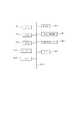
図1は、本実施形態における画像処理装置の構成を示す。同図に示すように、本実施形態における画像処理装置100は、第1画像撮影装置180と形状計測装置184とデータサーバ190とに接続されている。 FIG. 1 shows a configuration of an image processing apparatus according to the present embodiment. As shown in the figure, the image processing apparatus 100 in this embodiment is connected to a first
第1画像撮影装置180としての超音波装置は、プローブから超音波信号を送受信することによって仰臥位の対象物体を撮影する。撮影の際には、プローブの位置姿勢が位置姿勢センサで計測されているものとする。プローブの位置姿勢は、基準座標系(対象物体を基準とした空間中の座標系)における超音波断層画像の位置姿勢に変換した上で、超音波断層画像と対応付けられるものとする。ここで、位置姿勢センサは、プローブの位置姿勢が計測できるのであれば、どのように構成されていてもよく周知技術であるため説明は省略する。基準座標系で表現された超音波断層画像は、断層画像取得部102を介して画像処理装置100に逐次的に入力される。 The ultrasound device as the first image capturing
データサーバ190は、第2画像撮影装置182としてのMRI装置によって伏臥位で対象物体を撮影して得られた3次元画像(第1の3次元画像)を基準座標系に変換して保持しているものとする。データサーバ190が保持する第1の3次元画像は、3次元画像取得部104を介して画像処理装置100に入力される。 The
形状計測装置184としてのレンジセンサは、動的に変化する仰臥位の対象物体の表面形状を実時間で計測して形状データを得る。計測された形状データは、形状データ取得部105を介して画像処理装置100に逐次的に入力される。なお、形状計測装置184は、対象物体の形状を実時間で計測できるのであればどのように構成されていてもよく、レンジセンサに限らず、例えばステレオ画像計測装置などであってもよい。 The range sensor as the shape measuring device 184 obtains shape data by measuring the surface shape of the target object in the supine position that changes dynamically in real time. The measured shape data is sequentially input to the image processing apparatus 100 via the shape data acquisition unit 105. The shape measuring device 184 may be configured in any way as long as the shape of the target object can be measured in real time, and is not limited to the range sensor, and may be a stereo image measuring device, for example.
画像処理装置100は、以下に説明する構成要素により構成されている。 The image processing apparatus 100 is composed of the components described below.
断層画像取得部102は、画像処理装置100へと入力される超音波断層画像を逐次的に取得して、断面設定部108および画像合成部120へと出力する。ここで、超音波断層画像には基準座標系における位置姿勢の情報が付帯しているものとする。 The tomographic
3次元画像取得部104は、画像処理装置100へと入力される第1の3次元画像を取得し、変形データ生成部106及び対応断面画像生成部111へと出力する。 The three-dimensional
形状データ取得部105は、画像処理装置100へと入力される形状データを逐次的に取得し、変形データ生成部106へと出力する。 The shape data acquisition unit 105 sequentially acquires the shape data input to the image processing apparatus 100 and outputs it to the deformation
変形データ生成部106は、第1の3次元画像に変形処理を施し、計測した形状データと変形後の表面形状が略一致するような第2の3次元画像を生成し、これを断面画像生成部110へと出力する。ここで図示しない対応部200は、第1の3次元画像を第2の3次元画像に変形処理する際の各座標の対応関係を表す情報(以下、対応情報)を得てこれを保存する。この対応情報により第1の3次元画像の各座標と第2の3次元画像の各座標とが対応付けられる。また、第2の3次元画像を第1の3次元画像に逆変換するための3次元変位ベクトル群をこの対応情報に基づいて算出し、これを対応断面画像生成部111へと出力する。 The deformation
断面設定部108は、超音波断層画像に付帯する位置姿勢情報に基づいて第2の3次元画像中に断面を設定する。そのために、断層画像取得部102の出力である超音波断層画像を取得する。そして、その付帯情報である基準座標系における超音波断層画像の位置姿勢を、第2の3次元画像中における断面を表す平面の位置姿勢として、断面画像生成部110及び対応断面画像生成部111へと出力する。 The cross
断面画像生成部110は、第2の3次元画像中に設定した断面の画像を生成する。そのために、変形データ生成部106の出力である第2の3次元画像と、断面設定部108の出力である断面の位置姿勢とを取得する。そして、それらに基づいて断面の画像を生成して、画像合成部120へと出力する。 The cross-sectional
対応断面画像生成部111は、取得した各種の情報を利用して、第2の3次元画像中に設定した断面の、第1の3次元画像における対応断面の画像を生成する。そして、生成した画像を画像合成部120へと出力する。なお、対応断面画像生成部111の処理については、画像処理装置100が行う全体の処理手順を示すフローチャートを用いて、後に詳しく説明する。 The corresponding cross-section
画像合成部120は、超音波断層画像と断面の画像と対応断面の画像とを合成表示する。そのために、断層画像取得部102の出力である超音波断層画像と、断面画像生成部110の出力である断面の画像と、対応断面画像生成部111の出力である対応断面の画像とを取得する。そして、それらの画像を合成して表示する。 The
なお、図1に示した画像処理装置100の各部の少なくとも一部は、独立した装置として実現してもよい。または、夫々1つもしくは複数のコンピュータにインストールし、コンピュータのCPUにより実行することで、その機能を実現するソフトウェアとして実現してもよい。本実施形態では、各部は、それぞれソフトウェアにより実現され、同一のコンピュータにインストールされているものとする。 Note that at least a part of each unit of the image processing apparatus 100 illustrated in FIG. 1 may be realized as an independent apparatus. Alternatively, it may be implemented as software that implements its function by being installed in one or a plurality of computers and executed by the CPU of the computer. In the present embodiment, each unit is realized by software and installed in the same computer.
図2は、図1に示した各部の夫々の機能を、ソフトウェアを実行することで実現するためのコンピュータの基本構成を示す図である。 FIG. 2 is a diagram illustrating a basic configuration of a computer for realizing the functions of the respective units illustrated in FIG. 1 by executing software.
CPU1001は、RAM1002やROM1003に格納されたプログラムやデータを用いてコンピュータ全体の制御を行う。また、各部の夫々におけるソフトウェアの実行を制御して、各部の機能を実現する。 The
RAM1002は、外部記憶装置1007や記憶媒体ドライブ1008からロードされたプログラムやデータを一時的に記憶するエリアを備えると共に、CPU1001が各種の処理を行うために必要とするワークエリアを備える。 The
ROM1003は、一般にコンピュータのプログラムや設定データなどが格納されている。キーボード1004、マウス1005は入力デバイスであり、操作者はこれらを用いて、各種の指示をCPU1001に入力することができる。 The
表示部1006は、CRTや液晶ディスプレイなどにより構成されており、超音波断層画像や断面の画像や対応断面の画像の表示を行う。また、表示すべきメッセージやGUI等を表示することができる。 The
外部記憶装置1007は、ハードディスクドライブなどの大容量情報記憶装置として機能する装置であって、ここにOS(オペレーティングシステム)やCPU1001が実行するプログラム等を保存する。また本実施形態の説明において、既知であると説明する情報はここに保存されており、必要に応じてRAM1002にロードされる。 The
記憶媒体ドライブ1008は、CD−ROMやDVD−ROMなどの記憶媒体に記憶されているプログラムやデータをCPU1001からの指示に従って読み出して、RAM1002や外部記憶装置1007に出力する。 The
I/F1009は、アナログビデオポートあるいはIEEE1394等のデジタル入出力ポートや、各種の情報を外部へ出力するためのイーサネット(登録商標)ポート等によって構成される。夫々が入力したデータはI/F1009を介してRAM1002に取り込まれる。断層画像取得部102、3次元画像取得部104、および形状データ取得部105の機能の一部は、I/F1009によって実現される。 The I /
上述した各構成要素は、バス1010によって相互に接続される。 The above-described components are connected to each other by a
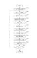
図3は、画像処理装置100が行う全体の処理手順を示すフローチャートである。なお、本実施形態では、同フローチャートはCPU1001が各部の機能を実現するプログラムを実行することにより実現される。なお、以下の処理を行う前段で、同フローチャートに従ったプログラムコードは、例えば外部記憶装置1007からRAM1002に既にロードされているものとする。 FIG. 3 is a flowchart showing an overall processing procedure performed by the image processing apparatus 100. In the present embodiment, the flowchart is realized by the
(S3000) (3次元データの取得)
ステップS3000において、画像処理装置100は、3次元画像取得部104の処理として、画像処理装置100へと入力される第1の3次元画像を取得する。(S3000) (Acquisition of three-dimensional data)
In step S3000, the image processing apparatus 100 acquires a first three-dimensional image input to the image processing apparatus 100 as processing of the three-dimensional
(S3005) (形状データの取得)
ステップS3000において、画像処理装置100は、形状データ取得部105の処理として、現時刻に画像処理装置100に入力されている最新の形状データを取得する。(S3005) (Acquisition of shape data)
In step S3000, the image processing apparatus 100 acquires the latest shape data input to the image processing apparatus 100 at the current time as processing of the shape data acquisition unit 105.
(S3010) (変形データの生成)
ステップS3010において、画像処理装置100は、変形データ生成部106の処理として、上記のステップで取得した第1の3次元画像と形状データに基づいて、第1の3次元画像に変形処理を施し第2の3次元画像を生成する。また、第2の3次元画像を第1の3次元画像に逆変換するための3次元変位ベクトル群を算出する。具体的には、まず、不図示の対応部200が、計測した形状データと第2の3次元画像の表面形状が略一致するという条件を用いて、第1の3次元画像から第2の3次元画像を生成するための情報として、画像間における各座標の対応関係を表す対応情報を求める。これには、例えば非特許文献1に開示されている手法を用いることができる。そして、この対応情報を用いて、第1の3次元画像に変形を施して第2の3次元画像を生成する。さらに、上記の対応情報に基づいて、第2の3次元画像を構成するボクセルの位置の夫々を変形前の第1の3次元画像を構成するボクセルの位置に逆変換するための3次元変位ベクトル群を算出する。(S3010) (Generation of deformation data)
In step S3010, the image processing apparatus 100 performs deformation processing on the first three-dimensional image based on the first three-dimensional image and the shape data acquired in the above step as processing of the deformation
(S3020) (超音波断層画像の取得)
ステップS3020において、画像処理装置100は、断層画像取得部102の処理として、現時刻に画像処理装置100に入力されている最新の超音波断層画像を、その付帯情報である基準座標系における位置姿勢とともに取得する。(S3020) (Acquisition of ultrasonic tomographic image)
In step S3020, as the processing of the tomographic
(S3030) (断面の設定)
ステップS3030において、画像処理装置100は、断面設定部108の処理として、ステップS3020で取得した超音波断層画像の基準座標系における位置姿勢を、断面を表す平面の位置姿勢として設定する。(S3030) (Cross section setting)
In step S3030, the image processing apparatus 100 sets the position and orientation in the reference coordinate system of the ultrasonic tomographic image acquired in step S3020 as the position and orientation of the plane representing the cross section as processing of the
(S3040) (断面画像の生成)
ステップS3040において、画像処理装置100は、断面画像生成部110の処理として、ステップS3010で生成した第2の3次元画像からステップS3030で設定した断面の所定の範囲を切り出した画像(断面画像)を生成する。ここで、指定した断面の画像を3次元画像から切り出して生成する方法については周知であるので、その詳細に関する説明は省略する。(S3040) (Cross-section image generation)
In step S3040, the image processing apparatus 100 performs processing by the cross-sectional
次に、画像処理装置100は、対応断面画像生成部111の中の近似平面算出部(不図示)の処理として、ステップS3050からステップS3070の処理により、第1の3次元画像における対応断面を近似する平面である近似平面を算出する。 Next, the image processing apparatus 100 approximates the corresponding cross section in the first three-dimensional image by the processing from step S3050 to step S3070 as the processing of the approximate plane calculation unit (not shown) in the corresponding cross section
(S3050) (グリッド点群の算出)
ステップS3050において、画像処理装置100は、対応断面画像生成部111の処理として、ステップS3030で設定した断面を表す平面の所定の範囲を等間隔に格子状に分割し、その交点群をグリッド点群として設定する。これらのグリッド点には、少なくとも、断面画像の中心位置を表す断面座標系(断面をXY平面とし、それと直交する軸をZ軸として定義した座標系)の原点が含まれている。また、ステップS3040で断面から画像を切り出した際の、所定の範囲を表す矩形領域の4頂点((−Xmin2,−Ymin2),(Xmin2,−Ymin2),(−Xmin2,Ymin2),(Xmin2,Ymin2))が含まれている。また、断面画像上における断面座標系のX・Y軸の夫々の端点((−Xmin2,0),(Xmin2,0),(0,−Ymin2),(0,Ymin2))が含まれている。そして、各グリッド点の基準座標系における位置を次式によって算出する。
xsn=xin・Tis
ここで、xin=[xin yin zin 1]Tは、断面座標系におけるn番目(n=1〜N;Nはグリッド点の総数)のグリッド点の位置の3次元空間における同次座標表現である。また、xsn=[xsn ysn zsn 1]Tは基準座標系におけるn番目のグリッド点の位置である。そしてTisは、ステップS3030で設定した断面の位置姿勢を表す、断面座標系から基準座標系への4x4の変換行列である。なお、夫々のグリッド点は断面上に存在するので、zin=0(n=1〜N)となる。(S3050) (Calculation of grid point group)
In step S3050, the image processing apparatus 100 divides the predetermined range of the plane representing the cross section set in step S3030 into a grid at equal intervals as the processing of the corresponding cross section
xsn = xin · Tis
Here, xin = [xin yin zin 1]T is the homogeneity in the three-dimensional space of the position of the nth grid point (n = 1 to N; N is the total number of grid points) in the cross-sectional coordinate system. Coordinate representation. Xsn = [xsn ysn zsn 1]T is the position of the nth grid point in the reference coordinate system. Tisis a 4 × 4 transformation matrix from the cross-sectional coordinate system to the reference coordinate system that represents the position and orientation of the cross-section set in step S3030. Since each grid point exists on the cross section, zin = 0 (n = 1 to N).
(S3060) (対応点群の算出)
ステップS3060において、画像処理装置100は、対応断面画像生成部111の処理として、ステップS3050で算出した各グリッド点の位置を、ステップS3010で算出した3次元変位ベクトル群に基づいて変位させる。そして、第2の3次元画像中におけるグリッド点群の変位後の位置に対応する第1の3次元画像中の点群(対応点群)の位置を算出する。具体的には、例えば各グリッド点の位置xsn(n=1〜N)に最も近接する第2の3次元画像を構成するボクセルを選択する。そして、選択されたボクセル位置における3次元変位ベクトルを各グリッド点の位置に足し合わせることで、第1の3次元画像中の対応点の位置xdn(n=1〜N)を算出する。なお、第1の3次元画像と第2の3次元画像は変形の状態が異なるため、対応点群xdn(n=1〜N)は一般的には同一平面上に位置しない。(S3060) (Calculation of corresponding point group)
In step S3060, the image processing apparatus 100 displaces the position of each grid point calculated in step S3050 based on the three-dimensional displacement vector group calculated in step S3010 as processing of the corresponding slice
(S3070) (近似平面の算出)
ステップS3070において、画像処理装置100は、対応断面画像生成部111の処理として、ステップS3060で算出した第1の3次元画像中の点群(対応点群)の位置に基づいて、対応点群を近似する平面を算出する。具体的には、対応点群xdn(n=1〜N)に最もよく当てはまる平面(近似平面)を、最小二乗法や最尤推定法などの一般的な平面当てはめ手法によって算出する。(S3070) (Calculation of approximate plane)
In step S3070, as a process of the corresponding cross-sectional
また、対応断面画像生成部111は、近似平面の算出方法を操作者が不図示のUIを用いて指定した場合には、指定された算出方法によって近似平面の算出を行う。例えば、ステップS3040で得た断面画像から夫々のグリッド点の近傍におけるエッジなどの画像特徴量の強度を抽出し、最小二乗法によって近似平面を求める際の対応点夫々の重みとしてこれを用いるという算出方法が選択できる。また、断面の原点を表すグリッド点の対応点位置を近似平面座標系の原点と定義して(位置を拘束して)、それ以外の対応点群に最もよく当てはまるような近似平面の姿勢を算出するという算出方法が選択できる。 Further, when the operator specifies a calculation method of the approximate plane using a UI (not shown), the corresponding slice
ここで、上記の処理で算出した近似平面には面内の位置と回転に自由度が残っているので、画像処理装置100はさらに、近似平面の面内移動成分の推定を行う。まず、断面の原点を表すグリッド点の対応点から上記近似平面に下ろした垂線の足を求め、その位置を近似平面座標系の原点とする(すなわち、近似平面の面内位置を決定する)。次に、断面のX軸上に位置するグリッド点の対応点の夫々から上記近似平面に下ろした垂線の足を求め、得られた点群を最も近似する直線を近似平面座標系のX軸とする(すなわち、近似平面座標系の面内回転を決定する)。 Here, since the in-plane position and the degree of freedom remain in the approximate plane calculated by the above processing, the image processing apparatus 100 further estimates the in-plane movement component of the approximate plane. First, a perpendicular foot drawn to the approximate plane is obtained from the corresponding point of the grid point representing the origin of the cross section, and the position is set as the origin of the approximate plane coordinate system (that is, the in-plane position of the approximate plane is determined). Next, a perpendicular line drawn from the corresponding points of the grid points located on the X axis of the cross section to the approximate plane is obtained, and the straight line that most closely approximates the obtained point group is defined as the X axis of the approximate plane coordinate system. (That is, determine the in-plane rotation of the approximate plane coordinate system).
さらに、画像処理装置100は、対応点群xdnの夫々から上記近似平面に下ろした垂線の足の全てを含んで、かつ、(−Xmin1,−Ymin1),(Xmin1,−Ymin1),(−Xmin1,Ymin1),(Xmin1,Ymin1)で記述可能な矩形の頂点座標を算出する。そして、この矩形を、次のステップで、対応断面画像の切り出しを行う際に用いる所定の範囲と定義する。Furthermore, the image processing apparatus 100 includes all the legs of the perpendicular linedropped from the corresponding point group xdn to the approximate plane, and (−Xmin1 , −Ymin1 ), (Xmin1 , −Ymin1). ), (−Xmin1 , Ymin1 ), (Xmin1 , Ymin1 ), the rectangular vertex coordinates that can be described are calculated. Then, this rectangle is defined as a predetermined range used when the corresponding cross-sectional image is cut out in the next step.
(S3080) (対応断面画像の生成)
ステップS3080において、画像処理装置100は、対応断面画像生成部111の処理として、第1の3次元画像からステップS3070で算出した近似平面の所定の範囲を切り出した画像を生成して、これを対応断面の画像(対応断面画像)とする。ここで、指定した平面の画像を3次元画像から切り出して生成する方法については周知であるので、その詳細に関する説明は省略する。(S3080) (Generation of corresponding cross-sectional image)
In step S3080, the image processing apparatus 100 generates an image obtained by cutting out the predetermined range of the approximate plane calculated in step S3070 from the first three-dimensional image as the process of the corresponding slice
また、対応断面画像生成部111は、対応断面画像の生成方法を操作者が不図示のUIを用いて指定した場合には、指定された生成方法によって対応断面画像の生成を行う。例えば、第1の3次元画像中の点群(対応点群)の位置に基づいて曲面を算出し、近似平面上の各画素の位置から延ばした垂線と曲面との交点の画素値を対応断面画像の各画素の画素値とする、という生成方法が選択できる。この生成方法によると、近似平面に対応点群を投影した画像が生成される。この場合、断面画像の真の対応断面(曲面)上の各画素を表示することができるため、断面画像との対比が容易となる。なお、曲面を算出する代わりに、対応点群を頂点とする3角形のパッチ群を算出してもよい。 In addition, when the operator specifies a corresponding slice image generation method using a UI (not shown), the corresponding slice
(S3090) (画像の合成)
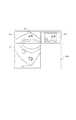
ステップS3090において、画像処理装置100は、画像合成部120の処理として、以下の処理を行う。すなわち、ステップS3020で取得した超音波断層画像と、ステップS3040で生成した断面画像と、ステップS3080で生成した対応断面画像とを、表示部1006に表示する。具体的には、図4に示すように、仰臥位の断面画像400(断面画像)を、乳頭401の側が略上向きとなるように(すなわち、胸壁が下方に位置するように)表示する。また、伏臥位の断面画像402(対応断面画像)を、乳頭403の側が略下向きとなるように(すなわち、胸壁が上方に位置するように)表示する。その際に、両者(400と402)の相対的な位置関係が、仰臥位の断面画像400が上側に、伏臥位の断面画像402が下側に位置するように、夫々の画像を配置して表示する。また、両者(400と402)が略上下対称の鏡像関係となるように、伏臥位の対応断面画像を左右反転させて表示する。なお、超音波断層画像404は断面画像400の左隣または右隣に表示すればよい。(S3090) (Image composition)
In step S <b> 3090, the image processing apparatus 100 performs the following processing as the processing of the
また、画像合成部120は、断面画像の表示方法を操作者が不図示のUIを用いて指定した場合には、指定された表示方法によって断面画像の表示を行う。例えば、仰臥位の断面画像400と伏臥位の断面画像402の何れも乳頭上向きで(すなわち、胸壁が下方に位置するように)、左右反転させずに表示するという表示方法が選択できる。すなわち、伏臥位の断面画像402を、乳頭下向きで左右反転させて表示するか、乳頭上向きで左右反転させずに表示するかを、操作者の好みによって選択できる。 In addition, when the operator designates the display method of the slice image using a UI (not shown), the
(S3100) (終了?)
ステップS3100において、画像処理装置100は、全体の処理を終了するか否かの判定を行う。例えば、表示部1006上に配置された終了ボタンを操作者がマウス1005でクリックするなどして、終了の判定を入力する。終了すると判定した場合には、画像処理装置100の処理の全体を終了させる。一方、終了すると判定しなかった場合には、ステップS3005へと処理を戻し、新たに取得される形状データと超音波断層画像に対して、ステップS3005からステップS3090までの処理を再度実行する。(S3100) (End?)
In step S3100, the image processing apparatus 100 determines whether to end the entire process. For example, when the operator clicks the end button arranged on the
以上によって、画像処理装置100の処理が実施される。 As described above, the processing of the image processing apparatus 100 is performed.
以上のように、本実施形態に係る画像処理装置は、変形後の3次元画像の断面に対応する変形前の3次元画像の対応断面を近似する平面を算出する。そうすることで、2つの3次元画像を同一形状に変形させることなく対応断面を算出して、それらの画像を表示することができる。さらに、体位の違いによって生じる変形前後の断面の画像を分かりやすく並べて表示して容易に比較することができる。 As described above, the image processing apparatus according to the present embodiment calculates a plane that approximates the corresponding cross section of the three-dimensional image before deformation corresponding to the cross section of the three-dimensional image after deformation. By doing so, it is possible to calculate the corresponding cross section without deforming the two three-dimensional images into the same shape, and display the images. Furthermore, images of cross sections before and after deformation caused by the difference in body posture can be displayed side by side in an easy-to-understand manner for easy comparison.
なお、本実施形態では、伏臥位のMRI画像を変形して仰臥位のMRI画像を仮想的に生成する場合を例に述べたが、本発明の実施はこれに限らない。例えば、本実施例とは逆に仰臥位のMRI画像を予め撮像しておき、それを変形して伏臥位のMRI画像を仮想的に生成してもよい。この場合には、変形前の仰臥位のMRI画像を変形後の伏臥位の3次元画像に変換するための3次元変位ベクトル群を保持しておけばよい。また、第1の変形条件下におけるMRI画像を変形して、複数の変形条件下における複数のMRI画像を生成する場合にも、本発明は好適に適用することができる。また、対象物体は人体の乳房に限らず、任意の対象物体であってもよい。 In the present embodiment, the case where the prone MRI image is virtually generated by deforming the prone MRI image has been described as an example, but the present invention is not limited to this. For example, contrary to the present embodiment, a supine position MRI image may be captured in advance, and the prone position MRI image may be virtually generated by deforming it. In this case, a three-dimensional displacement vector group for converting the MRI image in the supine position before deformation into the three-dimensional image in the prone position after deformation may be held. Also, the present invention can be suitably applied to the case where a plurality of MRI images under a plurality of deformation conditions are generated by deforming the MRI image under the first deformation conditions. Further, the target object is not limited to a human breast, and may be any target object.
(第1の実施形態の変形例1) (第2の3次元画像を予め取得)
本実施形態では、対象物体の第2の変形条件下における形状を実時間で計測して、第2の3次元画像と3次元変位ベクトル群を逐次的に算出する場合を例に述べた。しかし、対象物体の形状が第2の変形条件下において動的に変化しない場合(変化しないと仮定しても影響が少ない場合)には、予め生成しておいた第2の3次元画像を取得する構成であってもよい。(Modification 1 of 1st Embodiment) (The 2nd three-dimensional image is acquired beforehand)
In this embodiment, the case where the shape of the target object under the second deformation condition is measured in real time and the second three-dimensional image and the three-dimensional displacement vector group are sequentially calculated has been described as an example. However, when the shape of the target object does not change dynamically under the second deformation condition (when there is little influence even if it is assumed that it does not change), a second 3D image generated in advance is acquired. It may be configured to.
この場合、第1の3次元画像中の対象物体の形状が仰臥位における対象物体の形状と略一致するように、第1の3次元画像を予め変形させた3次元画像(第2の3次元画像)をデータサーバ190に保持しておく。また、変形後の第2の3次元画像を変形前の第1の3次元画像に逆変換するための3次元変位ベクトル群を予め算出し、基準座標系に変換した上でデータサーバ190に保持しておく。ここで、第2の3次元画像は、例えば非特許文献1に開示されている手法によって予め取得することができる。なお、仰臥位における対象物体の形状は、例えば形状計測装置184としてのレンジセンサや、ステレオ画像計測装置や、接触式のデジタイザなどを用いて、第2の変形条件下における対象物体の表面形状を計測することで取得できる。 In this case, a three-dimensional image (second three-dimensional image) obtained by deforming the first three-dimensional image in advance so that the shape of the target object in the first three-dimensional image substantially matches the shape of the target object in the supine position. Image) is stored in the
データサーバ190が保持する第1および第2の3次元画像と3次元変位ベクトル群は、3次元画像取得部104を介して画像処理装置100に入力される。 The first and second 3D images and the 3D displacement vector group held by the
3次元画像取得部104は、画像処理装置100へと入力される第1および第2の3次元画像と3次元変位ベクトル群を取得する。そして、第1の3次元画像と3次元変位ベクトル群を対応断面画像生成部111へと出力し、また、第2の3次元画像を断面画像生成部110へと出力する。 The three-dimensional
以上に説明した方法によれば、対象物体の形状が第2の変形条件下において動的に変化しない場合(変化しないと仮定しても影響が少ない場合)に、より簡便な構成で変形前後の3次元画像の対応断面を算出して、それらの画像を表示することができる。 According to the above-described method, when the shape of the target object does not change dynamically under the second deformation condition (when there is little influence even if it is assumed that the object does not change), a simpler configuration can be used before and after the deformation. The corresponding cross section of the three-dimensional image can be calculated and the images can be displayed.
(第1の実施形態の変形例2) (断面を指定する方法は何でもよい)
本実施形態では、超音波装置によって実時間で仰臥位の対象物体を撮像して得られる超音波断層画像の位置姿勢を断面の位置姿勢として設定する場合を例に述べた。しかし、断面を指定する方法はこれに限られるものではなく、3次元画像に対して断面を設定する一般的な方法のいずれの方法を用いてもよい。例えば、操作者がマウス1005やキーボード1004などを用いて、断面の回転方向および回転角度および各軸方向への移動を指定する一般的な方法を用いることができる。なお、位置姿勢センサなどを装着した位置姿勢指示具を操作者が移動および回転させることによって、当該センサの位置姿勢計測値を断面の位置姿勢として取得する構成であってもよい。(
In this embodiment, the case where the position and orientation of the ultrasonic tomographic image obtained by imaging the target object in the supine position in real time by the ultrasonic apparatus is set as the position and orientation of the cross section has been described as an example. However, the method for designating a cross section is not limited to this, and any of general methods for setting a cross section for a three-dimensional image may be used. For example, it is possible to use a general method in which the operator uses the
(第1の実施形態の変形例3) (MRI以外でもよい)
本実施形態では画像撮影装置2としてMRI装置を用いる場合を例として説明したが、本発明の実施はこれに限らない。例えば、X線CT装置、光音響トモグラフィ装置、OCT装置、PET/SPECT、3次元超音波装置などを用いることができる。(Modification 3 of the first embodiment) (Other than MRI)
Although the case where an MRI apparatus is used as the
(第1の実施形態の変形例4) (MIP画像でもよい)
本実施形態では、ステップS3040およびステップS3080の処理において、指定または算出した断面に基づいて、第1および第2の3次元画像の断面画像を生成していた。しかし、指定または算出した断面に基づいて3次元画像から画像を生成するものであれば、生成する断面画像は、その断面上のボクセル値を画像化した画像でなくてもよい。例えば、断面を中心として法線方向に所定の範囲を設定した上で、当該範囲内における法線方向のボクセル値の最大値を断面上の各点に関して求めた最大値投影画像を断面画像としてもよい。本発明では、指定または算出した断面に関して生成される上記のような画像も、広義の意味で「断面画像」に含めるものとする。(Modification 4 of the first embodiment) (MIP image may be used)
In the present embodiment, the cross-sectional images of the first and second three-dimensional images are generated based on the cross-sections designated or calculated in the processes of step S3040 and step S3080. However, if an image is generated from a three-dimensional image based on a specified or calculated cross section, the generated cross section image may not be an image obtained by imaging the voxel values on the cross section. For example, after setting a predetermined range in the normal direction around the cross section, the maximum value projection image obtained for each point on the cross section with the maximum value of the normal direction voxel value in the range may be used as the cross section image Good. In the present invention, the above-described image generated with respect to the designated or calculated cross section is also included in the “cross-sectional image” in a broad sense.
[第2の実施形態] (近似平面を病変位置に基づいて算出)
第1の実施形態では、対応点群に最もよく当てはまる平面(近似平面)を、最小二乗法や最尤推定法などの一般的な平面当てはめ手法によって算出する場合について説明した。しかし、近似平面の算出方法はこれに限らず、他の方法であってもよい。また、第1の実施形態では、変形後の3次元画像において断面を指定して、これに対応する変形前の3次元画像における対応断面の画像を生成する場合を例に述べた。しかし、変形前後の3次元画像の対応する断面を表示する方法はこれに限らない。本実施形態に係る画像処理装置は、変形前のMRI画像中の断面に対応する変形後のMRI画像中の対応断面(曲面)の近似平面を、MRI画像中の注目点位置(病変位置)に基づいて算出する。そして、断面の画像と対応断面の画像とを生成して並べて表示する。以下、本実施形態に係る画像処理装置について、第1の実施形態との相違部分についてのみ説明する。Second Embodiment (Calculating an approximate plane based on a lesion position)
In the first embodiment, the case where the plane (approximate plane) best applied to the corresponding point group is calculated by a general plane fitting method such as the least square method or the maximum likelihood estimation method has been described. However, the method of calculating the approximate plane is not limited to this, and other methods may be used. Further, in the first embodiment, the case where a cross section is specified in a three-dimensional image after deformation and an image of a corresponding cross section in the three-dimensional image before deformation corresponding thereto is generated is described as an example. However, the method of displaying the corresponding cross section of the three-dimensional image before and after the deformation is not limited to this. The image processing apparatus according to the present embodiment uses the approximate plane of the corresponding cross section (curved surface) in the MRI image after deformation corresponding to the cross section in the MRI image before deformation as the position of interest (lesion position) in the MRI image. Calculate based on Then, a cross-sectional image and a corresponding cross-sectional image are generated and displayed side by side. Hereinafter, only the difference from the first embodiment of the image processing apparatus according to the present embodiment will be described.
図5は、本実施形態に係る画像処理装置の構成を示す。なお、図1と同じ部分については同じ番号、記号を付けており、その説明を省略する。図5に示すように、本実施形態における画像処理装置500は、データサーバ590に接続されている。 FIG. 5 shows a configuration of the image processing apparatus according to the present embodiment. The same parts as those in FIG. 1 are given the same numbers and symbols, and the description thereof is omitted. As shown in FIG. 5, the
データサーバ590は、第2画像撮影装置182としてのMRI装置によって伏臥位で対象物体を撮影して得られた3次元画像(第1の3次元画像)と、第1の3次元画像中における病変位置(第1の病変位置)を保持する。また、データサーバ590は、第1の3次元画像中の対象物体の形状(第1の形状)が仰臥位における対象物体の形状と略一致するように、第1の3次元画像を予め変形させた3次元画像(第2の3次元画像)も保持する。さらに、データサーバ590は、画像間における各座標の対応関係を表す情報(対応情報)として、予め算出された、変形前の第1の3次元画像を変形後の第2の3次元画像に変換するための3次元変位ベクトル群を、基準座標系に変換した上で保持する。データサーバ590が保持する第1および第2の3次元画像と3次元変位ベクトル群は、3次元画像取得部504を介して画像処理装置500に入力される。また、データサーバ590が保持する第1の病変位置は、位置取得部503を介して画像処理装置500に入力される。 The data server 590 includes a three-dimensional image (first three-dimensional image) obtained by photographing a target object in a prone position with an MRI apparatus as the second
位置取得部503は、画像処理装置500へと入力される第1の病変位置を注目点の位置として取得し、変形データ生成部506および対応断面画像生成部511へと出力する。 The position acquisition unit 503 acquires the first lesion position input to the
3次元画像取得部504は、画像処理装置500へと入力される第1および第2の3次元画像と3次元変位ベクトル群を取得する。そして、第1の3次元画像を断面画像生成部510へと出力する。また、第2の3次元画像と3次元変位ベクトル群を対応断面画像生成部511へと出力する。さらに、3次元変位ベクトル群を変形データ生成部506へと出力する。このように、本実施形態では、画像間の対応情報を取得する対応部200(不図示)の機能を、3次元画像取得部504が備えている。 変形データ生成部506は、取得した第1の病変位置と3次元変位ベクトル群に基づいて、第1の病変位置に対応する第2の3次元画像中の位置(第2の病変位置)を算出し、対応断面画像生成部511へと出力する。 The three-dimensional
なお、第2の病変位置を変形データ部506で算出するのではなく、予め算出してデータサーバ590に保持しておいてもよい。この場合、位置取得部503がデータサーバ590から第2の病変位置を取得し、対応断面画像生成部511へと出力する。 Note that the second lesion position may be calculated in advance and stored in the data server 590 instead of being calculated by the deformation data unit 506. In this case, the position acquisition unit 503 acquires the second lesion position from the data server 590 and outputs it to the corresponding slice image generation unit 511.
断面設定部508は、操作者がマウス1005等を用いて画像処理装置500へと入力した、平面の回転方向および回転角度および各軸方向への移動を指定する情報を取得し、その情報に基づいて第1の3次元画像中に断面を設定する。そして、第1の3次元画像中における断面を表す平面の位置姿勢を、断面画像生成部510及び対応断面画像生成部511へと出力する。 The
断面画像生成部510は、第1の3次元画像中に設定した断面の画像を生成する。そのために、3次元画像取得部504の出力である第1の3次元画像と、断面設定部508の出力である断面の位置姿勢とを取得する。そして、それらに基づいて断面の画像を生成して、画像合成部520へと出力する。 The cross-sectional
対応断面画像生成部511は、取得した各種の情報を利用して、第1の3次元画像中に設定した断面の、第1の3次元画像における対応断面の画像を生成する。そして、生成した画像を画像合成部520へと出力する。なお、対応断面画像生成部511の処理については、画像処理装置500が行う全体の処理手順を示すフローチャートを用いて、後に詳しく説明する。 The corresponding cross-section image generation unit 511 generates an image of the corresponding cross section in the first three-dimensional image of the cross section set in the first three-dimensional image using the various types of acquired information. Then, the generated image is output to the
画像合成部520は、断面の画像と対応断面の画像とを合成表示する。そのために、断面画像生成部510の出力である断面の画像と、対応断面画像生成部511の出力である対応断面の画像とを取得する。そして、それらの画像を合成して表示する。 The
なお、画像処理装置500を構成する上記各部の夫々の機能をソフトウェアの実行によって実現するコンピュータの基本構成は、第1の実施形態における図2と同様である。 Note that the basic configuration of a computer that realizes the functions of the above-described units constituting the
図6は、画像処理装置500が行う全体の処理手順を示すフローチャートである。同フローチャートは、本実施形態ではCPU1001が各部の機能を実現するプログラムを実行することにより実現される。なお、以下の処理を行う前段で、同フローチャートに従ったプログラムコードは、例えば外部記憶装置1007からRAM1002に既にロードされているものとする。 FIG. 6 is a flowchart showing an overall processing procedure performed by the
(S6000) (3次元データの取得)
ステップS6000において、画像処理装置500は、3次元画像取得部504の処理として、画像処理装置100へと入力される第1、第2の3次元画像および3次元変位ベクトル群を取得する。(S6000) (Acquisition of three-dimensional data)
In step S6000, the
(S6005) (病変位置の取得)
ステップS6005において、画像処理装置500は、位置取得部503の処理として、データサーバ590から画像処理装置100へと入力される第1の病変位置(例えば図7の712に示す病変部の重心位置)を取得する。(S6005) (Acquisition of lesion position)
In step S <b> 6005, the
(S6010) (変形データの生成)
ステップS6010において、画像処理装置500は、変形データ生成部506の処理として、取得した3次元変位ベクトル群に基づいて、第1の病変位置に対応する第2の3次元画像中の位置(第2の病変位置)を算出する。例えば、第1の病変位置に最も近接する第1の3次元画像を構成するボクセルを選択し、選択されたボクセル位置における3次元変位ベクトルを第1の病変位置に足し合わせることで、第2の病変位置を得る。図7の例では、710に示す病変部の重心位置が算出される。(S6010) (Generation of deformation data)
In step S6010, the
(S6030) (断面の設定)
ステップS6030において、画像処理装置500は、断面設定部508の処理として、操作者の指定に基づいて、断面を表す平面の位置姿勢を設定する。(S6030) (Cross section setting)
In step S <b> 6030, the
(S6040) (断面画像の生成)
ステップS6040において、画像処理装置500は、断面画像生成部510の処理として、ステップS6000で取得した第1の3次元画像からステップS6030で設定した断面の所定の範囲を切り出した画像(断面画像)を生成する。(S6040) (Generation of cross-sectional image)
In step S6040, the
次に、画像処理装置500は、対応断面画像生成部511の中の近似平面算出部(不図示)の処理として、ステップS6050からステップS6070の処理により、第2の3次元画像における対応断面を近似する平面である近似平面を算出する。 Next, the
ステップS6050の処理は、第1の実施形態におけるステップS3050の処理と同様であるので、詳細な説明は省略する。 Since the process of step S6050 is the same as the process of step S3050 in the first embodiment, detailed description thereof is omitted.
(S6060) (対応点群の算出)
ステップS6060において、画像処理装置500は、対応断面画像生成部511の処理として、ステップS6050で算出した各グリッド点の位置を、ステップS6000で取得した3次元変位ベクトル群に基づいて変位させる。そして、第1の3次元画像中におけるグリッド点群の変位後の位置に対応する第2の3次元画像中の点群(対応点群)の位置を算出する。具体的には、例えば各グリッド点の位置xsn(n=1〜N)に最も近接する第1の3次元画像を構成するボクセルを選択する。そして、選択されたボクセル位置における3次元変位ベクトルを各グリッド点の位置に足し合わせることで、第2の3次元画像中の対応点の位置xdn(n=1〜N)を算出する。(S6060) (Calculation of corresponding point group)
In step S6060, the
(S6070) (近似平面の算出)
ステップS6070において、画像処理装置500は、対応断面画像生成部511の処理として、以下の処理を行う。すなわち、ステップS6000で取得した第1の病変位置と、ステップS6010で算出した第2の病変位置と、ステップS6060で算出した第2の3次元画像中の点群(対応点群)の位置とに基づいて、対応点群の近似平面を算出する。具体的には、第1の病変位置から断面までの距離と第2の病変位置から近似平面までの距離とが等しいという制約条件の下で、対応点群xdn(n=1〜N)に当てはまる近似平面を最小二乗法によって算出する。(S6070) (Calculation of approximate plane)
In step S6070, the
また、対応断面画像生成部111は、近似平面の算出方法を操作者が不図示のUIを用いて指定した場合には、指定された算出方法によって近似平面の算出を行う。例えば、第2の病変位置から夫々の対応点までの距離に応じて夫々の対応点に重みを付け、重みつきの最小二乗法によって近似平面を求めるという算出方法が選択できる。また、病変位置に関する情報を利用せずに、第1の実施形態におけるステップS3070の処理と同様な算出方法(例えば、対応点群からの距離の和を最小化する平面を最小二乗法によって求める算出方法)が選択できる。 Further, when the operator specifies a calculation method of the approximate plane using a UI (not shown), the corresponding slice
なお、平面算出後の処理(面内移動成分の推定と対応断面画像の切り出し範囲の算出)に関しては、第1の実施形態におけるステップS3070の処理と同様であるので、説明を省略する。 The processing after plane calculation (estimation of the in-plane moving component and calculation of the cutout range of the corresponding cross-sectional image) is the same as the processing in step S3070 in the first embodiment, and thus description thereof is omitted.
(S6080) (対応断面画像の生成)
ステップS6080において、画像処理装置500は、対応断面画像生成部511の処理として、第2の3次元画像からステップS6070で算出した近似平面を切り出した画像を生成して、これを対応断面の画像(対応断面画像)とする。(S6080) (Generation of Corresponding Section Image)
In step S6080, the
(S6090) (画像の合成)
ステップS6090において、画像処理装置500は、画像合成部520の処理として、ステップS6040で生成した断面画像とステップS6080で生成した対応断面画像とを表示部1006に表示する。具体的には、図7に示すように、伏臥位の断面画像702(断面画像)を乳頭703が略下向きとなるように下側に表示し、仰臥位の断面画像700(対応断面画像)を乳頭701が略上向きとなるように上側に表示する。その際に、両者(700と702)が略上下対称の鏡像関係となるように、伏臥位の断面画像を左右反転させて表示する。(S6090) (Image composition)
In step S6090, the
また、画像合成部520は、断面画像の表示方法を操作者が不図示のUIを用いて指定した場合には、指定された表示方法によって断面画像の表示を行う。例えば、伏臥位の断面画像と仰臥位の断面画像の何れも乳頭上向きで、左右反転させずに表示するという表示方法が選択できる。また、仰臥位の断面画像を乳頭上向きで左右反転させて表示して、伏臥位の断面画像を乳頭下向きで左右反転させずに表示する(すなわち、左右反転させる画像を伏臥位から仰臥位に変更する)という表示方法が選択できる。 In addition, when the operator designates the display method of the cross-sectional image using a UI (not shown), the
(S6100) (終了?)
ステップS6100において、画像処理装置500は、全体の処理を終了するか否かの判定を行う。例えば、表示部1006上に配置された終了ボタンを操作者がマウス1005でクリックするなどして、終了の判定を入力する。終了すると判定した場合には、画像処理装置500の処理の全体を終了させる。一方、終了すると判定しなかった場合には、ステップS6030へと処理を戻し、ステップS6030からステップS6090までの処理を再度実行する。(S6100) (End?)
In step S6100, the
以上によって、画像処理装置500の処理が実施される。 Thus, the processing of the
以上のように、本実施形態に係る画像処理装置は、変形前の3次元画像の断面に対応する変形後の3次元画像の対応断面を近似する平面を病変位置に基づいて算出する。そうすることで、2つの3次元画像を同一形状に変形させることなく対応断面を算出して、それらの画像を表示することができる。さらに、体位の違いによって生じる変形前後の断面の画像を分かりやすく並べて表示して容易に比較することができる。その際に、病変付近の様子を容易に比較することができる。 As described above, the image processing apparatus according to the present embodiment calculates a plane that approximates the corresponding cross section of the three-dimensional image after deformation corresponding to the cross section of the three-dimensional image before deformation based on the lesion position. By doing so, it is possible to calculate the corresponding cross section without deforming the two three-dimensional images into the same shape, and display the images. Furthermore, images of cross sections before and after deformation caused by the difference in body posture can be displayed side by side in an easy-to-understand manner for easy comparison. At that time, the state near the lesion can be easily compared.
(第2の実施形態の変形例1) (超音波断層画像で断面を指定してもよい)
本実施形態では、変形前の3次元画像において断面を指定して、これに対応する変形後の3次元画像における対応断面の画像を生成する場合を例に述べた。しかし、第1の実施形態と同様に、変形後の3次元画像において断面を指定して、これに対応する変形前の3次元画像における対応断面の画像を生成して表示してもよい。この場合の対応断面画像の生成方法は第1の実施形態と同様であるので、詳細な説明は省略する。また、変形前後の何れの3次元画像においても断面の指定が可能であって、一方の3次元画像で断面を指定すると、他方の3次元画像の対応断面を生成して表示するという構成であってもよい。(Modification 1 of 2nd Embodiment) (A cross section may be designated by an ultrasonic tomographic image)
In the present embodiment, an example has been described in which a cross section is specified in a three-dimensional image before deformation, and an image of a corresponding cross section in the three-dimensional image after deformation corresponding thereto is generated. However, similarly to the first embodiment, a cross section may be specified in the three-dimensional image after deformation, and an image of the corresponding cross section in the three-dimensional image before deformation corresponding thereto may be generated and displayed. Since the method for generating the corresponding cross-sectional image in this case is the same as in the first embodiment, detailed description thereof is omitted. In addition, it is possible to specify a cross section in any three-dimensional image before and after the deformation, and when a cross section is specified in one of the three-dimensional images, a corresponding cross section of the other three-dimensional image is generated and displayed. May be.
(第2の実施形態の変形例2) (病変位置をサーバが保持しなくてもよい)
本実施形態では、第1の3次元画像中における病変位置(第1の病変位置)をデータサーバ590が保持する場合を例に述べた。しかし、これに限らず、データサーバ590は病変位置を保持せずに、画像処理装置500の処理の一部として第1の病変位置を設定してもよい。(
In this embodiment, the case where the data server 590 holds the lesion position (first lesion position) in the first three-dimensional image has been described as an example. However, the present invention is not limited to this, and the data server 590 may set the first lesion position as part of the processing of the
例えば、3次元画像中における任意の座標を指定する一般的なUIを用いて、第1の3次元画像中の病変部の重心位置を操作者が指定して、その位置を第1の病変位置として設定してもよい。例えば、断面画像中に病変部が描出された時に、その重心(例えば、図7の712の中心付近)を操作者がマウス1005等を用いて指定して、その位置を第1の病変位置として設定してもよい。この場合、近似平面算出部は、ステップS6070において、第1の病変位置が指定されるまでは、第1の実施形態と同様に病変位置には基づかずに対応点群の位置に基づいて近似平面を算出する。そして、第1の病変位置が設定されたら、それ以降は、その位置に基づいて近似平面を算出する。 For example, using a general UI for designating arbitrary coordinates in the three-dimensional image, the operator designates the barycentric position of the lesioned part in the first three-dimensional image, and the position is designated as the first lesion position. May be set as For example, when a lesion is depicted in a cross-sectional image, the operator designates the center of gravity (for example, near the center of 712 in FIG. 7) using the
なお、病変位置は、画像処理による病変の自動検出の結果に基づいて設定してもよい。この場合、病変の自動検出の信頼度に応じて、ステップS6070で近似平面を算出する際の重みを変えてもよい。例えば、信頼度を0から1までの実数値で算出して、重みの値に掛け合わせてもよい。 The lesion position may be set based on the result of automatic lesion detection by image processing. In this case, the weight for calculating the approximate plane in step S6070 may be changed according to the reliability of the automatic detection of the lesion. For example, the reliability may be calculated as a real value from 0 to 1 and multiplied by the weight value.
[その他の実施形態]
以上、実施形態を詳述したが、本発明は、例えば、システム、装置、方法、プログラムもしくは記憶媒体等としての実施態様をとることが可能である。具体的には、複数の機器から構成されるシステムに適用してもよいし、また、一つの機器からなる装置に適用してもよい。[Other Embodiments]
Although the embodiment has been described in detail above, the present invention can take an embodiment as a system, apparatus, method, program, storage medium, or the like. Specifically, the present invention may be applied to a system composed of a plurality of devices, or may be applied to an apparatus composed of a single device.
尚、本発明は、ソフトウェアのプログラムをシステム或いは装置に直接或いは遠隔から供給し、そのシステム或いは装置のコンピュータが該供給されたプログラムコードを読み出して実行することによって前述した実施形態の機能が達成される場合を含む。この場合、供給されるプログラムは実施形態で図に示したフローチャートに対応したコンピュータプログラムである。 In the present invention, the functions of the above-described embodiments are achieved by supplying a software program directly or remotely to a system or apparatus, and the computer of the system or apparatus reads and executes the supplied program code. Including the case. In this case, the supplied program is a computer program corresponding to the flowchart shown in the drawings in the embodiment.
従って、本発明の機能処理をコンピュータで実現するために、該コンピュータにインストールされるプログラムコード自体も本発明を実現するものである。つまり、本発明は、本発明の機能処理を実現するためのコンピュータプログラム自体も含まれる。 Accordingly, since the functions of the present invention are implemented by computer, the program code installed in the computer also implements the present invention. In other words, the present invention includes a computer program itself for realizing the functional processing of the present invention.
その場合、プログラムの機能を有していれば、オブジェクトコード、インタプリタにより実行されるプログラム、OSに供給するスクリプトデータ等の形態であってもよい。 In that case, as long as it has the function of a program, it may be in the form of object code, a program executed by an interpreter, script data supplied to the OS, and the like.
コンピュータプログラムを供給するためのコンピュータ読み取り可能な記憶媒体としては以下が挙げられる。例えば、フロッピー(登録商標)ディスク、ハードディスク、光ディスク、光磁気ディスク、MO、CD−ROM、CD−R、CD−RW、磁気テープ、不揮発性のメモリカード、ROM、DVD(DVD−ROM、DVD−R)などである。 Examples of the computer-readable storage medium for supplying the computer program include the following. For example, floppy (registered trademark) disk, hard disk, optical disk, magneto-optical disk, MO, CD-ROM, CD-R, CD-RW, magnetic tape, nonvolatile memory card, ROM, DVD (DVD-ROM, DVD- R).
その他、プログラムの供給方法としては、クライアントコンピュータのブラウザを用いてインターネットのホームページに接続し、該ホームページから本発明のコンピュータプログラムをハードディスク等の記録媒体にダウンロードすることが挙げられる。この場合、ダウンロードされるプログラムは、圧縮され自動インストール機能を含むファイルであってもよい。また、本発明のプログラムを構成するプログラムコードを複数のファイルに分割し、それぞれのファイルを異なるホームページからダウンロードすることによっても実現可能である。つまり、本発明の機能処理をコンピュータで実現するためのプログラムファイルを複数のユーザに対してダウンロードさせるWWWサーバも、本発明に含まれるものである。 As another program supply method, a client computer browser is used to connect to a homepage on the Internet, and the computer program of the present invention is downloaded from the homepage to a recording medium such as a hard disk. In this case, the downloaded program may be a compressed file including an automatic installation function. It can also be realized by dividing the program code constituting the program of the present invention into a plurality of files and downloading each file from a different homepage. That is, a WWW server that allows a plurality of users to download a program file for realizing the functional processing of the present invention on a computer is also included in the present invention.
また、本発明のプログラムを暗号化してCD−ROM等の記憶媒体に格納してユーザに配布するという形態をとることもできる。この場合、所定の条件をクリアしたユーザに、インターネットを介してホームページから暗号を解く鍵情報をダウンロードさせ、その鍵情報を使用して暗号化されたプログラムを実行し、プログラムをコンピュータにインストールさせるようにもできる。 Further, the program of the present invention may be encrypted, stored in a storage medium such as a CD-ROM, and distributed to users. In this case, a user who has cleared a predetermined condition is allowed to download key information for decryption from a homepage via the Internet, execute an encrypted program using the key information, and install the program on the computer. You can also.
また、コンピュータが、読み出したプログラムを実行することによって、前述した実施形態の機能が実現される他、そのプログラムの指示に基づき、コンピュータ上で稼動しているOSなどとの協働で実施形態の機能が実現されてもよい。この場合、OSなどが、実際の処理の一部または全部を行い、その処理によって前述した実施形態の機能が実現される。 In addition to the functions of the above-described embodiment being realized by the computer executing the read program, the embodiment of the embodiment is implemented in cooperation with an OS or the like running on the computer based on an instruction of the program. A function may be realized. In this case, the OS or the like performs part or all of the actual processing, and the functions of the above-described embodiments are realized by the processing.
さらに、記録媒体から読み出されたプログラムが、コンピュータに挿入された機能拡張ボードやコンピュータに接続された機能拡張ユニットに備わるメモリに書き込まれて前述の実施形態の機能の一部或いは全てが実現されてもよい。この場合、機能拡張ボードや機能拡張ユニットにプログラムが書き込まれた後、そのプログラムの指示に基づき、その機能拡張ボードや機能拡張ユニットに備わるCPUなどが実際の処理の一部または全部を行う。 Furthermore, the program read from the recording medium is written in a memory provided in a function expansion board inserted into the computer or a function expansion unit connected to the computer, so that part or all of the functions of the above-described embodiments are realized. May be. In this case, after a program is written in the function expansion board or function expansion unit, the CPU or the like provided in the function expansion board or function expansion unit performs part or all of the actual processing based on the instructions of the program.
100 画像処理装置
102 断層画像取得部
104 3次元画像取得部
105 形状データ取得部
106 変形データ生成部
108 断面設定部
110 断面画像生成部
111 対応断面画像生成部
120 画像合成部
200 対応部DESCRIPTION OF SYMBOLS 100
Claims (10)
Translated fromJapanese前記第1の3次元画像、前記第2の3次元画像のいずれか一方に設定された断面に対応する他方の3次元画像の断面画像を、前記対応情報に基づいて生成する対応断面画像生成手段と、
を備えることを特徴とする画像処理装置。Correspondence means for obtaining correspondence information between the first three-dimensional image of the target object and the second three-dimensional image of the target object;
Corresponding cross-sectional image generation means for generating a cross-sectional image of the other three-dimensional image corresponding to the cross-section set to one of the first three-dimensional image and the second three-dimensional image based on the correspondence information When,
An image processing apparatus comprising:
前記対応断面画像生成手段は、前記対応情報と前記位置とに基づいて前記断面画像を生成することを特徴とする請求項1に記載の画像処理装置。A position acquisition means for acquiring a position in the first three-dimensional image or the second three-dimensional image;
The image processing apparatus according to claim 1, wherein the corresponding cross-sectional image generation unit generates the cross-sectional image based on the correspondence information and the position.
前記第2の3次元画像における断面を超音波断層画像によって設定する断面設定手段を有し、
前記対応断面画像生成手段は、前記断面設定手段で設定された断面に対応する断面画像を前記第1の3次元画像から生成することを特徴とする請求項1に記載の画像処理装置。The first three-dimensional image is an image obtained by photographing the target object, and the second three-dimensional image is an image obtained by deforming the first three-dimensional image,
Cross-section setting means for setting a cross-section in the second three-dimensional image by an ultrasonic tomographic image;
The image processing apparatus according to claim 1, wherein the corresponding cross-sectional image generation unit generates a cross-sectional image corresponding to the cross-section set by the cross-section setting unit from the first three-dimensional image.
前記第2の3次元画像に関する断面の画像を乳頭が上向きで、前記第1の3次元画像に関する断面の画像を乳頭が下向きで表示手段に表示させる制御手段をさらに備えることを特徴とする請求項1に記載の画像処理装置。The first three-dimensional image is an image obtained by imaging a breast in a prone position, and the second three-dimensional image is an image obtained by transforming the first three-dimensional image into a supine position,
The apparatus further comprises control means for causing the display means to display a cross-sectional image related to the second three-dimensional image with a nipple facing upward and a cross-sectional image related to the first three-dimensional image facing downward. The image processing apparatus according to 1.
前記第1の3次元画像、前記第2の3次元画像のいずれか一方に設定された断面に対応する他方の3次元画像の断面画像を、前記対応情報に基づいて生成する対応断面画像生成工程と、
を備えることを特徴とする画像処理方法。A corresponding step of acquiring correspondence information between the first three-dimensional image of the target object and the second three-dimensional image of the target object;
Corresponding cross-sectional image generation step of generating a cross-sectional image of the other three-dimensional image corresponding to a cross-section set to one of the first three-dimensional image and the second three-dimensional image based on the correspondence information When,
An image processing method comprising:
Priority Applications (3)
| Application Number | Priority Date | Filing Date | Title |
|---|---|---|---|
| JP2009288457AJP5538862B2 (en) | 2009-12-18 | 2009-12-18 | Image processing apparatus, image processing system, image processing method, and program |
| US12/969,178US8582856B2 (en) | 2009-12-18 | 2010-12-15 | Image processing apparatus, image processing method, and program |
| US14/051,168US8917924B2 (en) | 2009-12-18 | 2013-10-10 | Image processing apparatus, image processing method, and program |
Applications Claiming Priority (1)
| Application Number | Priority Date | Filing Date | Title |
|---|---|---|---|
| JP2009288457AJP5538862B2 (en) | 2009-12-18 | 2009-12-18 | Image processing apparatus, image processing system, image processing method, and program |
Publications (2)
| Publication Number | Publication Date |
|---|---|
| JP2011125570Atrue JP2011125570A (en) | 2011-06-30 |
| JP5538862B2 JP5538862B2 (en) | 2014-07-02 |
Family
ID=44151190
Family Applications (1)
| Application Number | Title | Priority Date | Filing Date |
|---|---|---|---|
| JP2009288457AActiveJP5538862B2 (en) | 2009-12-18 | 2009-12-18 | Image processing apparatus, image processing system, image processing method, and program |
Country Status (2)
| Country | Link |
|---|---|
| US (2) | US8582856B2 (en) |
| JP (1) | JP5538862B2 (en) |
Cited By (11)
| Publication number | Priority date | Publication date | Assignee | Title |
|---|---|---|---|---|
| JP2011224211A (en)* | 2010-04-21 | 2011-11-10 | Canon Inc | Image processing apparatus, image processing method, and program |
| JP2011239974A (en)* | 2010-05-19 | 2011-12-01 | Ge Medical Systems Global Technology Co Llc | Ultrasound diagnostic apparatus |
| WO2013021711A1 (en)* | 2011-08-11 | 2013-02-14 | 株式会社 日立メディコ | Ultrasound diagnostic device and ultrasound image display method |
| JP2013150825A (en)* | 2013-03-22 | 2013-08-08 | Ge Medical Systems Global Technology Co Llc | Image display device |
| JP2014018376A (en)* | 2012-07-17 | 2014-02-03 | Canon Inc | Image processing device and method |
| WO2014034948A1 (en)* | 2012-09-03 | 2014-03-06 | 株式会社東芝 | Ultrasonic diagnostic apparatus and image processing method |
| JP2014140717A (en)* | 2012-12-28 | 2014-08-07 | Canon Inc | Subject information obtaining apparatus, display method, and program |
| JP2014140718A (en)* | 2012-12-28 | 2014-08-07 | Canon Inc | Subject information obtaining apparatus, display method, and program |
| EP3273409A1 (en) | 2016-07-19 | 2018-01-24 | Canon Kabushiki Kaisha | Image processing apparatus and image processing method |
| JP2018167077A (en)* | 2018-08-01 | 2018-11-01 | キヤノン株式会社 | Processing device, processing method, and program |
| US10699424B2 (en) | 2016-07-19 | 2020-06-30 | Canon Kabushiki Kaisha | Image processing apparatus, image processing method, and non-transitory computer readable medium with generation of deformed images |
Families Citing this family (11)
| Publication number | Priority date | Publication date | Assignee | Title |
|---|---|---|---|---|
| JP6025349B2 (en)* | 2012-03-08 | 2016-11-16 | キヤノン株式会社 | Image processing apparatus, optical coherence tomography apparatus, image processing method, and optical coherence tomography method |
| FR2994263B1 (en)* | 2012-08-02 | 2018-09-07 | Vit | METHOD AND DEVICE FOR IDENTIFYING MATERIALS IN A SCENE |
| US10631780B2 (en)* | 2012-12-05 | 2020-04-28 | Philips Image Guided Therapy Corporation | System and method for non-invasive tissue characterization |
| CN104224329B (en)* | 2013-06-18 | 2017-08-25 | 台湾植体科技股份有限公司 | Dental handpiece accessory system and its operating method |
| JP6397269B2 (en)* | 2013-09-06 | 2018-09-26 | キヤノン株式会社 | Image processing apparatus and image processing method |
| WO2015066458A1 (en)* | 2013-11-01 | 2015-05-07 | The Research Foundation For The State University Of New York | Method for measuring the interior three-dimensional movement, stress and strain of an object |
| JP6362420B2 (en)* | 2014-05-26 | 2018-07-25 | キヤノン株式会社 | Subject information acquisition apparatus, subject information acquisition method, and program |
| JP6376873B2 (en)* | 2014-07-16 | 2018-08-22 | キヤノン株式会社 | Image processing apparatus, image processing method, and program |
| US9808213B2 (en)* | 2014-08-11 | 2017-11-07 | Canon Kabushiki Kaisha | Image processing apparatus, image processing method, medical image diagnostic system, and storage medium |
| CN107920859B (en) | 2015-08-17 | 2020-12-08 | 皇家飞利浦有限公司 | Simulating breast deformation |
| CN109256193A (en)* | 2018-09-04 | 2019-01-22 | 北京慧影明图科技有限公司 | Image display method and apparatus, storage medium, electric terminal |
Citations (7)
| Publication number | Priority date | Publication date | Assignee | Title |
|---|---|---|---|---|
| JP2001511031A (en)* | 1997-01-24 | 2001-08-07 | メイヨ ファンデーション フォー メディカル エデュケーション アンド リサーチ | System for two- and three-dimensional imaging of tubular structures in the human body |
| JP2003144412A (en)* | 2001-11-14 | 2003-05-20 | Ge Medical Systems Global Technology Co Llc | Image diagnosis support system and image processing method |
| JP2004016374A (en)* | 2002-06-14 | 2004-01-22 | Hitachi Medical Corp | Medical image pickup apparatus |
| JP2006217939A (en)* | 2005-02-08 | 2006-08-24 | Hitachi Medical Corp | Image display device |
| JP2008086400A (en)* | 2006-09-29 | 2008-04-17 | Gifu Univ | Breast diagnostic imaging system |
| JP2009000328A (en)* | 2007-06-22 | 2009-01-08 | Hitachi Medical Corp | Magnetic resonance imaging method |
| JP2009077780A (en)* | 2007-09-25 | 2009-04-16 | Toshiba Corp | Breast examination system |
Family Cites Families (37)
| Publication number | Priority date | Publication date | Assignee | Title |
|---|---|---|---|---|
| US4787393A (en)* | 1985-11-20 | 1988-11-29 | Matsushita Electric Industrial Co., Ltd. | Ultrasonic tomographic with alternate image scaling |
| US5561696A (en)* | 1987-10-30 | 1996-10-01 | Hewlett-Packard Company | Method and apparatus for inspecting electrical connections |
| US5200910A (en)* | 1991-01-30 | 1993-04-06 | The Board Of Trustees Of The Leland Stanford University | Method for modelling the electron density of a crystal |
| JP3580627B2 (en)* | 1996-01-29 | 2004-10-27 | 株式会社東芝 | Ultrasound diagnostic equipment |
| US7191110B1 (en)* | 1998-02-03 | 2007-03-13 | University Of Illinois, Board Of Trustees | Patient specific circulation model |
| US7142703B2 (en)* | 2001-07-17 | 2006-11-28 | Cedara Software (Usa) Limited | Methods and software for self-gating a set of images |
| JP4958348B2 (en)* | 2001-09-06 | 2012-06-20 | 株式会社日立メディコ | Ultrasonic imaging device |
| US7218766B2 (en)* | 2002-04-15 | 2007-05-15 | General Electric Company | Computer aided detection (CAD) for 3D digital mammography |
| US7260426B2 (en)* | 2002-11-12 | 2007-08-21 | Accuray Incorporated | Method and apparatus for tracking an internal target region without an implanted fiducial |
| US7831296B2 (en)* | 2002-11-27 | 2010-11-09 | Hologic, Inc. | X-ray mammography with tomosynthesis |
| CA2519187A1 (en)* | 2003-03-25 | 2004-10-14 | Imaging Therapeutics, Inc. | Methods for the compensation of imaging technique in the processing of radiographic images |
| US7379576B2 (en)* | 2003-11-03 | 2008-05-27 | Siemens Medical Solutions Usa, Inc. | Method and system for patient identification in 3D digital medical images |
| US7727151B2 (en)* | 2003-11-28 | 2010-06-01 | U-Systems Inc. | Navigation among multiple breast ultrasound volumes |
| US7672705B2 (en)* | 2004-07-19 | 2010-03-02 | Resonant Medical, Inc. | Weighted surface-to-surface mapping |
| JP2006061472A (en)* | 2004-08-27 | 2006-03-09 | Fuji Photo Film Co Ltd | Breast image display device, and program therefor |
| WO2007015365A1 (en)* | 2005-08-01 | 2007-02-08 | National University Corporation NARA Institute of Science and Technology | Information processing device and program |
| US8086010B2 (en)* | 2006-06-30 | 2011-12-27 | Kabushiki Kaisha Toshiba | Medical image diagnosis apparatus and the control method thereof |
| JP4757142B2 (en)* | 2006-08-10 | 2011-08-24 | キヤノン株式会社 | Imaging environment calibration method and information processing apparatus |
| JP2008073305A (en) | 2006-09-22 | 2008-04-03 | Gifu Univ | Ultrasonic breast diagnosis system |
| JP4751282B2 (en)* | 2006-09-27 | 2011-08-17 | 株式会社日立製作所 | Ultrasonic diagnostic equipment |
| JP5148094B2 (en)* | 2006-09-27 | 2013-02-20 | 株式会社東芝 | Ultrasonic diagnostic apparatus, medical image processing apparatus, and program |
| JP4851298B2 (en)* | 2006-10-31 | 2012-01-11 | 富士フイルム株式会社 | Radiation tomographic image generator |
| US7734328B2 (en)* | 2006-12-21 | 2010-06-08 | General Electric Company | System and method to enhance visualization of an object in a vascular vessel |
| US10682107B2 (en)* | 2007-01-31 | 2020-06-16 | Philips Digital Mammography Sweden Ab | Method and arrangement relating to x-ray imaging |
| CN104398240B (en)* | 2007-06-25 | 2017-06-20 | 真实成像有限公司 | Methods, devices and systems for analyzing image |
| US20110255761A1 (en)* | 2007-06-26 | 2011-10-20 | University Of Rochester | Method and system for detecting lung tumors and nodules |
| JP2009018115A (en)* | 2007-07-13 | 2009-01-29 | Toshiba Corp | 3D ultrasonic diagnostic equipment |
| US8290303B2 (en)* | 2007-10-11 | 2012-10-16 | General Electric Company | Enhanced system and method for volume based registration |
| US20090129650A1 (en)* | 2007-11-19 | 2009-05-21 | Carestream Health, Inc. | System for presenting projection image information |
| CN101969877B (en)* | 2007-12-21 | 2014-01-29 | 3M创新有限公司 | Orthodontic treatment monitoring based on reduced images |
| JP4444346B2 (en)* | 2008-05-22 | 2010-03-31 | ザイオソフト株式会社 | Medical image processing method and medical image processing program |
| US20110144500A1 (en)* | 2008-07-22 | 2011-06-16 | Hitachi Medical Corporation | Ultrasonic diagnostic apparatus and method for calculating coordinates of scanned surface thereof |
| WO2010017356A2 (en)* | 2008-08-08 | 2010-02-11 | University Of Pittsburgh - Of The Commonwealth System Of Higher Education | Establishing compatibility between two-and three dimensional optical coherence tomography scans |
| US8131046B2 (en)* | 2008-10-29 | 2012-03-06 | Allegheny-Singer Research Institute | Magnetic resonance imager using cylindrical offset region of excitation, and method |
| JP5147656B2 (en)* | 2008-11-20 | 2013-02-20 | キヤノン株式会社 | Image processing apparatus, image processing method, program, and storage medium |
| JP5737858B2 (en)* | 2010-04-21 | 2015-06-17 | キヤノン株式会社 | Image processing apparatus, image processing method, and program |
| US20120155727A1 (en)* | 2010-12-15 | 2012-06-21 | General Electric Company | Method and apparatus for providing motion-compensated images |
- 2009
- 2009-12-18JPJP2009288457Apatent/JP5538862B2/enactiveActive
- 2010
- 2010-12-15USUS12/969,178patent/US8582856B2/ennot_activeExpired - Fee Related
- 2013
- 2013-10-10USUS14/051,168patent/US8917924B2/enactiveActive
Patent Citations (7)
| Publication number | Priority date | Publication date | Assignee | Title |
|---|---|---|---|---|
| JP2001511031A (en)* | 1997-01-24 | 2001-08-07 | メイヨ ファンデーション フォー メディカル エデュケーション アンド リサーチ | System for two- and three-dimensional imaging of tubular structures in the human body |
| JP2003144412A (en)* | 2001-11-14 | 2003-05-20 | Ge Medical Systems Global Technology Co Llc | Image diagnosis support system and image processing method |
| JP2004016374A (en)* | 2002-06-14 | 2004-01-22 | Hitachi Medical Corp | Medical image pickup apparatus |
| JP2006217939A (en)* | 2005-02-08 | 2006-08-24 | Hitachi Medical Corp | Image display device |
| JP2008086400A (en)* | 2006-09-29 | 2008-04-17 | Gifu Univ | Breast diagnostic imaging system |
| JP2009000328A (en)* | 2007-06-22 | 2009-01-08 | Hitachi Medical Corp | Magnetic resonance imaging method |
| JP2009077780A (en)* | 2007-09-25 | 2009-04-16 | Toshiba Corp | Breast examination system |
Cited By (20)
| Publication number | Priority date | Publication date | Assignee | Title |
|---|---|---|---|---|
| JP2011224211A (en)* | 2010-04-21 | 2011-11-10 | Canon Inc | Image processing apparatus, image processing method, and program |
| JP2011239974A (en)* | 2010-05-19 | 2011-12-01 | Ge Medical Systems Global Technology Co Llc | Ultrasound diagnostic apparatus |
| JPWO2013021711A1 (en)* | 2011-08-11 | 2015-03-05 | 株式会社日立メディコ | Ultrasonic diagnostic apparatus and ultrasonic image display method |
| WO2013021711A1 (en)* | 2011-08-11 | 2013-02-14 | 株式会社 日立メディコ | Ultrasound diagnostic device and ultrasound image display method |
| CN103732150A (en)* | 2011-08-11 | 2014-04-16 | 株式会社日立医疗器械 | Ultrasound diagnostic device and ultrasound image display method |
| US10546377B2 (en) | 2012-07-17 | 2020-01-28 | Canon Kabushiki Kaisha | Image processing apparatus and method, and processing system |
| JP2014018376A (en)* | 2012-07-17 | 2014-02-03 | Canon Inc | Image processing device and method |
| US9767549B2 (en) | 2012-07-17 | 2017-09-19 | Canon Kabushiki Kaisha | Image processing apparatus and method, and processing system |
| WO2014034948A1 (en)* | 2012-09-03 | 2014-03-06 | 株式会社東芝 | Ultrasonic diagnostic apparatus and image processing method |
| US9524551B2 (en) | 2012-09-03 | 2016-12-20 | Toshiba Medical Systems Corporation | Ultrasound diagnosis apparatus and image processing method |
| JP2014061291A (en)* | 2012-09-03 | 2014-04-10 | Toshiba Corp | Ultrasonic diagnostic equipment and image processing method |
| JP2014140718A (en)* | 2012-12-28 | 2014-08-07 | Canon Inc | Subject information obtaining apparatus, display method, and program |
| JP2014140717A (en)* | 2012-12-28 | 2014-08-07 | Canon Inc | Subject information obtaining apparatus, display method, and program |
| US10429233B2 (en) | 2012-12-28 | 2019-10-01 | Canon Kabushiki Kaisha | Object information obtaining device, display method, and non-transitory computer-readable storage medium |
| JP2013150825A (en)* | 2013-03-22 | 2013-08-08 | Ge Medical Systems Global Technology Co Llc | Image display device |
| EP3273409A1 (en) | 2016-07-19 | 2018-01-24 | Canon Kabushiki Kaisha | Image processing apparatus and image processing method |
| US10366544B2 (en) | 2016-07-19 | 2019-07-30 | Canon Kabushiki Kaisha | Image processing apparatus, image processing method, and non-transitory computer-readable medium |
| US10699424B2 (en) | 2016-07-19 | 2020-06-30 | Canon Kabushiki Kaisha | Image processing apparatus, image processing method, and non-transitory computer readable medium with generation of deformed images |
| US10796498B2 (en) | 2016-07-19 | 2020-10-06 | Canon Kabushiki Kaisha | Image processing apparatus, image processing method, and non-transitory computer-readable medium |
| JP2018167077A (en)* | 2018-08-01 | 2018-11-01 | キヤノン株式会社 | Processing device, processing method, and program |
Also Published As
| Publication number | Publication date |
|---|---|
| US8917924B2 (en) | 2014-12-23 |
| US20140037176A1 (en) | 2014-02-06 |
| US20110150310A1 (en) | 2011-06-23 |
| US8582856B2 (en) | 2013-11-12 |
| JP5538862B2 (en) | 2014-07-02 |
Similar Documents
| Publication | Publication Date | Title |
|---|---|---|
| JP5538862B2 (en) | Image processing apparatus, image processing system, image processing method, and program | |
| JP6312898B2 (en) | Information processing apparatus, information processing method, and program | |
| CN102727258B (en) | Image processing apparatus, ultrasonic photographing system, and image processing method | |
| JP5430203B2 (en) | Image processing apparatus and image processing method | |
| JP4709177B2 (en) | Three-dimensional image processing apparatus and method, and program | |
| JP5538861B2 (en) | Information processing apparatus, information processing method, information processing system, and program | |
| JP6039903B2 (en) | Image processing apparatus and operation method thereof | |
| US20110262015A1 (en) | Image processing apparatus, image processing method, and storage medium | |
| JP6200249B2 (en) | Information processing apparatus and information processing method | |
| JP5631453B2 (en) | Image processing apparatus and image processing method | |
| JP2011125568A (en) | Image processor, image processing method, program and image processing system | |
| KR101504162B1 (en) | Information processing apparatus for medical images, imaging system for medical images, and information processing method for medical images | |
| JP5415245B2 (en) | MEDICAL IMAGE DISPLAY DEVICE, METHOD, AND PROGRAM | |
| JP6429958B2 (en) | Image processing apparatus, image processing method, and program | |
| JP5383467B2 (en) | Image processing apparatus, image processing method, image processing system, and program | |
| JP6487999B2 (en) | Information processing apparatus, information processing method, and program | |
| JP5709957B2 (en) | Image processing apparatus, image processing method, image processing system, and program | |
| JP2010240141A (en) | Information processor, image diagnostic system, and display control method of image for diagnosis | |
| JP6263248B2 (en) | Information processing apparatus, information processing method, and program | |
| JP6251002B2 (en) | Image processing apparatus, image processing method, and computer program | |
| JP2012147939A (en) | Image processing apparatus | |
| JP6391544B2 (en) | Medical image processing apparatus, medical image processing method, and program | |
| JP2017202399A (en) | Information processing apparatus and information processing method |
Legal Events
| Date | Code | Title | Description |
|---|---|---|---|
| A621 | Written request for application examination | Free format text:JAPANESE INTERMEDIATE CODE: A621 Effective date:20121127 | |
| A131 | Notification of reasons for refusal | Free format text:JAPANESE INTERMEDIATE CODE: A131 Effective date:20130924 | |
| A977 | Report on retrieval | Free format text:JAPANESE INTERMEDIATE CODE: A971007 Effective date:20130927 | |
| A521 | Request for written amendment filed | Free format text:JAPANESE INTERMEDIATE CODE: A523 Effective date:20131125 | |
| A131 | Notification of reasons for refusal | Free format text:JAPANESE INTERMEDIATE CODE: A131 Effective date:20140107 | |
| A521 | Request for written amendment filed | Free format text:JAPANESE INTERMEDIATE CODE: A523 Effective date:20140310 | |
| TRDD | Decision of grant or rejection written | ||
| A01 | Written decision to grant a patent or to grant a registration (utility model) | Free format text:JAPANESE INTERMEDIATE CODE: A01 Effective date:20140401 | |
| R151 | Written notification of patent or utility model registration | Ref document number:5538862 Country of ref document:JP Free format text:JAPANESE INTERMEDIATE CODE: R151 | |
| A61 | First payment of annual fees (during grant procedure) | Free format text:JAPANESE INTERMEDIATE CODE: A61 Effective date:20140430 |