JP2011125540A - Golf club head - Google Patents
Golf club headDownload PDFInfo
- Publication number
- JP2011125540A JP2011125540AJP2009287878AJP2009287878AJP2011125540AJP 2011125540 AJP2011125540 AJP 2011125540AJP 2009287878 AJP2009287878 AJP 2009287878AJP 2009287878 AJP2009287878 AJP 2009287878AJP 2011125540 AJP2011125540 AJP 2011125540A
- Authority
- JP
- Japan
- Prior art keywords
- golf club
- club head
- adhesive material
- sole
- hosel
- Prior art date
- Legal status (The legal status is an assumption and is not a legal conclusion. Google has not performed a legal analysis and makes no representation as to the accuracy of the status listed.)
- Pending
Links
Images


Classifications
- A—HUMAN NECESSITIES
- A63—SPORTS; GAMES; AMUSEMENTS
- A63B—APPARATUS FOR PHYSICAL TRAINING, GYMNASTICS, SWIMMING, CLIMBING, OR FENCING; BALL GAMES; TRAINING EQUIPMENT
- A63B53/00—Golf clubs
- A63B53/04—Heads
- A63B53/0466—Heads wood-type
- A—HUMAN NECESSITIES
- A63—SPORTS; GAMES; AMUSEMENTS
- A63B—APPARATUS FOR PHYSICAL TRAINING, GYMNASTICS, SWIMMING, CLIMBING, OR FENCING; BALL GAMES; TRAINING EQUIPMENT
- A63B53/00—Golf clubs
- A63B53/04—Heads
- A63B53/0433—Heads with special sole configurations
- A—HUMAN NECESSITIES
- A63—SPORTS; GAMES; AMUSEMENTS
- A63B—APPARATUS FOR PHYSICAL TRAINING, GYMNASTICS, SWIMMING, CLIMBING, OR FENCING; BALL GAMES; TRAINING EQUIPMENT
- A63B53/00—Golf clubs
- A63B53/04—Heads
- A63B53/0437—Heads with special crown configurations
- A—HUMAN NECESSITIES
- A63—SPORTS; GAMES; AMUSEMENTS
- A63B—APPARATUS FOR PHYSICAL TRAINING, GYMNASTICS, SWIMMING, CLIMBING, OR FENCING; BALL GAMES; TRAINING EQUIPMENT
- A63B2209/00—Characteristics of used materials
- A63B2209/10—Characteristics of used materials with adhesive type surfaces, i.e. hook and loop-type fastener
- A—HUMAN NECESSITIES
- A63—SPORTS; GAMES; AMUSEMENTS
- A63B—APPARATUS FOR PHYSICAL TRAINING, GYMNASTICS, SWIMMING, CLIMBING, OR FENCING; BALL GAMES; TRAINING EQUIPMENT
- A63B53/00—Golf clubs
- A63B53/04—Heads
- A63B53/0408—Heads characterised by specific dimensions, e.g. thickness
- A—HUMAN NECESSITIES
- A63—SPORTS; GAMES; AMUSEMENTS
- A63B—APPARATUS FOR PHYSICAL TRAINING, GYMNASTICS, SWIMMING, CLIMBING, OR FENCING; BALL GAMES; TRAINING EQUIPMENT
- A63B60/00—Details or accessories of golf clubs, bats, rackets or the like
- A63B60/002—Resonance frequency related characteristics
Landscapes
- Health & Medical Sciences (AREA)
- General Health & Medical Sciences (AREA)
- Physical Education & Sports Medicine (AREA)
- Life Sciences & Earth Sciences (AREA)
- Engineering & Computer Science (AREA)
- Wood Science & Technology (AREA)
- Golf Clubs (AREA)
Abstract
Translated fromJapaneseDescription
Translated fromJapanese本発明は中空のゴルフクラブヘッドに係り、特に内部に異物を付着させるための粘着材を設けたゴルフクラブヘッドに関する。 The present invention relates to a hollow golf club head, and more particularly to a golf club head provided with an adhesive material for adhering foreign matter inside.
ドライバーやフェアウェーウッドなどのウッド型ゴルフクラブヘッドとして、中空の金属製のものが広く用いられている。一般に、中空のウッド型のゴルフクラブヘッドは、ボールをヒットするためのフェース部と、ゴルフクラブヘッドの上面部を構成するクラウン部と、ゴルフクラブヘッドの底面部を構成するソール部と、ゴルフクラブヘッドのトウ側、バック側及びヒール側の側面部を構成するサイド部と、ホゼル部とを有している。このホゼル部にシャフトが挿入され、接着剤等によってシャフトがゴルフクラブヘッドに固定されることにより、ゴルフクラブが構成される。 Hollow metal golf club heads such as drivers and fairway woods are widely used. In general, a hollow wood-type golf club head includes a face portion for hitting a ball, a crown portion constituting an upper surface portion of the golf club head, a sole portion constituting a bottom surface portion of the golf club head, and a golf club. It has a side part constituting a side part on the toe side, back side and heel side of the head, and a hosel part. A shaft is inserted into the hosel portion, and the shaft is fixed to the golf club head with an adhesive or the like, thereby forming a golf club.
この中空ゴルフクラブヘッドを構成する金属としては、アルミニウム合金、ステンレスやチタン合金が用いられている。なお、ゴルフクラブヘッドの一部を繊維強化合成樹脂にて構成することもある。 As a metal constituting the hollow golf club head, an aluminum alloy, stainless steel, or titanium alloy is used. A part of the golf club head may be made of fiber reinforced synthetic resin.
中空ゴルフクラブヘッドの内部に金属の微小片等よりなる異物が存在すると、ゴルフクラブを動かしたときに該異物がゴルフクラブヘッド内を移動し、チリチリあるいはカラカラといった異音が発生する。このような異物としては、金属製ゴルフクラブヘッドの鋳造滓などが挙げられる。 If there is a foreign object such as a fine metal piece inside the hollow golf club head, the foreign object will move in the golf club head when the golf club is moved, and an abnormal noise such as a dusty or an unevenness will be generated. An example of such a foreign material is a cast iron of a metal golf club head.
特開平7−148288には、ゴルフクラブヘッド内に粘着材層を設けることにより異物粒子を付着させて捕獲することが記載されている。この特開平7−148288では、粘着材層はソール部やクラウン部の内面に広い範囲にわたって設けられている。 Japanese Patent Application Laid-Open No. 7-148288 describes that foreign particles are attached and captured by providing an adhesive layer in a golf club head. In JP-A-7-148288, the adhesive material layer is provided over a wide range on the inner surface of the sole portion or the crown portion.
粘着材層を中空ゴルフクラブヘッドの内部に付着させた場合、ボールを打ったときのゴルフクラブヘッドの一次固有振動数が低下し、打球音の周波数が小さくなり、打球音の音域が低音となる。特に、上記特開平7−148288のように粘着材層をソール部の広い範囲に設けた場合、ソール部の一次固有振動数が小さくなり、「カキーン」というメタルヘッド特有の甲高い爽快な打球音が生じなくなる。そのため、ゴルフクラブ使用者(プレーヤー)は、ナイスショットをしている場合であってもミスショットをしたのではないかという誤解を抱くことがある。 When the adhesive layer is attached to the inside of the hollow golf club head, the primary natural frequency of the golf club head when the ball is hit is reduced, the frequency of the hitting sound is reduced, and the sound range of the hitting sound is low. . In particular, when the adhesive material layer is provided in a wide range of the sole portion as in JP-A-7-148288, the primary natural frequency of the sole portion is reduced, and a high-pitched and refreshing hitting sound peculiar to a metal head called “Kakeen” is produced. No longer occurs. Therefore, the golf club user (player) may have a misunderstanding that he / she has made a miss shot even if he / she is a nice shot.
本発明は、このような問題点を解決し、爽快な打球音を発するゴルフクラブヘッドを提供することを目的とする。 An object of the present invention is to provide a golf club head that solves such problems and emits a refreshing hitting sound.
本発明(請求項1)のゴルフクラブヘッドは、少なくともフェース部、ソール部、サイド部、クラウン部及びホゼル部を有する中空のゴルフクラブヘッドであって、該ゴルフクラブヘッドの内面の一部に、異物を付着させるための粘着材が設けられているゴルフクラブヘッドにおいて、該ソール部に、該粘着材の配置領域を区画するための凸条部を設け、該粘着材を該配置領域に配置したことを特徴とするものである。 The golf club head of the present invention (Claim 1) is a hollow golf club head having at least a face portion, a sole portion, a side portion, a crown portion, and a hosel portion, and a part of the inner surface of the golf club head, In the golf club head provided with an adhesive material for adhering foreign matter, the sole portion is provided with a ridge for partitioning the placement area of the adhesive material, and the adhesive material is placed in the placement area. It is characterized by this.
請求項2のゴルフクラブヘッドは、請求項1において、前記凸条部は前記フェース部から離隔していることを特徴とするものである。 According to a second aspect of the present invention, the golf club head according to the first aspect is characterized in that the protruding portion is separated from the face portion.
請求項3のゴルフクラブヘッドは、請求項1において、前記凸条部は、前記フェース部のうちヒール側に連なっていることを特徴とするものである。 A golf club head according to a third aspect of the present invention is the golf club head according to the first aspect, wherein the ridge portion is connected to the heel side of the face portion.
請求項4のゴルフクラブヘッドは、請求項1ないし3のいずれか1項において、前記ホゼル部は、ゴルフクラブヘッド内外を連通するように貫通しており、前記配置領域は、該ホゼル部の下方領域であることを特徴とするものである。 A golf club head according to a fourth aspect of the present invention is the golf club head according to any one of the first to third aspects, wherein the hosel portion passes through the golf club head so as to communicate with the inside and outside of the golf club head, It is a region.
請求項5のゴルフクラブヘッドは、請求項1ないし4のいずれか1項において、前記凸条部は、その全体が、前記ソール部のトウ・ヒール方向の中間よりもヒール側に設けられていることを特徴とするものである。 According to a fifth aspect of the present invention, in the golf club head according to any one of the first to fourth aspects, the entire protrusion is provided on the heel side with respect to the middle of the sole portion in the toe-heel direction. It is characterized by this.
本発明のゴルフクラブヘッドは、内部に粘着材を備えており、異物が付着して捕集されるので、異物が動くことによる異音が防止される。 The golf club head of the present invention includes an adhesive material inside, and foreign matter adheres and is collected, so that noise due to the movement of the foreign matter is prevented.
本発明では、ソール部に凸条部を設けて粘着材の配置領域を区画し、粘着材をこの配置領域に配置しているので、粘着材はソール部のうち限られた範囲のみ存在する。そのため、粘着材を設けたことによるボールヒット時におけるソール部の一次固有振動数の低下が抑制され、粘着材を入れていないゴルフクラブヘッドと大差ない打球音が発生するようになる。 In the present invention, the protruding portion is provided in the sole portion to partition the adhesive material arrangement area, and the adhesive material is arranged in the arrangement area. Therefore, the adhesive material is present only in a limited range of the sole portion. Therefore, a decrease in the primary natural frequency of the sole portion at the time of a ball hit due to the provision of the adhesive material is suppressed, and a hitting sound that is not much different from a golf club head not containing an adhesive material is generated.
この凸条部をフェース部から離隔させた場合、ボールヒット時におけるフェース部の撓みに影響がなく、ボール打ち出し速度が大きいものとなる。ただし、凸条部がフェース部のヒール側に連なるようにした場合にも、ボールヒット時におけるフェース部の撓みに殆ど影響がなく、ボール打ち出し速度が大きいものとなる。 When the convex portion is separated from the face portion, the deflection of the face portion at the time of a ball hit is not affected, and the ball launch speed is high. However, even when the ridges are connected to the heel side of the face part, there is almost no effect on the deflection of the face part at the time of a ball hit, and the ball launch speed is high.
なお、ホゼル部が貫通穴状である場合、ホゼル部にシャフトを差し込む際などにホゼル部内面やシャフト先端に付着していた異物がゴルフクラブヘッド内に入り込むおそれがある。粘着材配置領域をホゼル部の下方領域に設定しておくと、ホゼル部から落下してきた異物がそのまま粘着材上に落下して捕集されるので、異物に起因した異音発生が確実に防止される。また、ホゼル部から加熱溶融状態の粘着材をゴルフクラブヘッド内に注入したときに、粘着材が凸条部で堰止められ、凸条部よりもヒール側の粘着材配置領域に粘着材が配置される。 In the case where the hosel portion has a through hole shape, there is a possibility that foreign matter adhering to the inner surface of the hosel portion or the shaft tip may enter the golf club head when the shaft is inserted into the hosel portion. If the adhesive material placement area is set in the lower area of the hosel part, the foreign matter that has fallen from the hosel part will fall onto the adhesive material as it is and be collected, so it is possible to reliably prevent the generation of abnormal noise caused by the foreign matter. Is done. In addition, when a hot-melt adhesive material is injected into the golf club head from the hosel part, the adhesive material is blocked by the ridges, and the adhesive material is arranged in the adhesive material arrangement region on the heel side of the ridges. Is done.
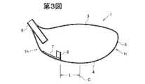
以下、図面を参照して実施の形態について説明する。第1図〜第3図は第1の実施の形態に係るゴルフクラブヘッドを示している。なお、ゴルフクラブヘッド1の構造を明確にするために、第1図では粘着材の図示が省略されている。 Hereinafter, embodiments will be described with reference to the drawings. 1 to 3 show a golf club head according to a first embodiment. In order to clarify the structure of the golf club head 1, the adhesive material is not shown in FIG.
このゴルフクラブヘッド1は、フェース部2と、クラウン部3と、ソール部4と、サイド部5と、ホゼル部6とを有する中空形状であり、全体としてチタン合金などの金属にて一体に構成されている。金属としては、チタン、チタン合金、アルミ合金、ステンレスなど各種のものを用いることができる。ゴルフクラブヘッドの容積は350cc以上例えば400〜460cc程度であることが好ましい。 This golf club head 1 has a hollow shape having a
ホゼル部6は、第3図の通り貫通穴形状である。このホゼル部6の下端の下方領域を粘着材7の配置領域とするために、ソール部4に凸条部8が突設されている。この実施の形態では、凸条部8は、平面視において前部8aと後部8bとが略々直交状に交わったL字形状である。前部8aと後部8bとの交わり部が最もヒール1hから遠い(トウ1tに近い)ものとなっており、前端側及び後端側ほどヒール1hに近づいている。 The
この凸条部8の前端はフェース部2との間から若干(例えば1〜10mm特に2〜5mm)離隔している。この凸条部8の後端は、ヒール1h側のサイド部5に連なっているが、若干(例えば2〜5mm程度)離隔していてもよい。この凸条部8よりもヒール1h側が粘着材7の配置領域である。この凸条部8は、その全体が、ゴルフクラブヘッド1のトウ1tとヒール1hとを結ぶトウ・ヒール方向の中間Cよりもヒール1h側に位置している。容積400〜460cc程度のゴルフクラブヘッドの場合、この中間Cから凸条部8の最もトウ側までの距離L(第3図)は10mm以上例えば12〜30mm程度が好ましい。 The front end of the ridge 8 is slightly separated from the face 2 (for example, 1 to 10 mm, particularly 2 to 5 mm). The rear end of the ridge portion 8 is continuous with the
凸条部8はソール部4と一体の金属製の壁状である。壁の最も高い部分のソール部4からの高さは1〜10mm特に2〜5mm程度が好適である。凸条部8の壁の厚さは3mm以下、例えば0.5〜1.5mm程度が好適である。 The ridge portion 8 has a metal wall shape integral with the
粘着材7としては、粘着付与剤と熱可塑性エラストマーの混合物が好ましく、例えば、粘着付与剤としては、ロジンエステル樹脂、ロジンエステル樹脂、テルペンフェノール樹脂、テルペン樹脂、低分子量のブチルゴム、ポリブテン樹脂などを用い、これに、熱可塑性樹脂または、ポリスチレン系エラストマー、ポリウレタンエラストマーなどの各種エラストマーを混ぜたものが好ましい。ゴルフクラブヘッド1の重量を徒に増大させないようにするために、粘着材7の重量は15g以下例えば2〜12g程度であることが好ましい。 The
この粘着材7は、好ましくは、注入ノズル(図示略)をホゼル部6に通し、加温して粘度を低くして該注入ノズルから配置領域に注入されることにより設けられる。凸条部8を設けてあるので、この粘着材7はソール部4の中心側にまで広がることはなく、粘着材7は前記配置領域に配置される。 This
ソール部4の厚さは0.5〜1.2mm程度が好適である。 The thickness of the
このように構成されたゴルフクラブヘッド1は、内部に粘着材7を備えており、異物が付着して捕集されるので、異物が動くことによる異音が防止される。また、ソール部4に凸条部8を設けて粘着材7の配置領域を区画し、粘着材7をこの配置領域にのみ配置しているので、粘着材7はソール部4のうち限られた範囲にのみ存在する。そのため、粘着材を設けたことによるボールヒット時におけるソール部4の一次固有振動数の低下が抑制され、粘着材を入れていないゴルフクラブヘッドと大差ない打球音が発生するようになる。 The golf club head 1 configured as described above includes an adhesive 7 inside, and foreign matter adheres and is collected, so that abnormal noise due to the movement of the foreign matter is prevented. Further, the protruding portion 8 is provided on the
なお、本発明者の研究によると、打球音の発生部位としてはソール部4が主要部となる。そのため、ソール部4の一次固有振動数を高目に保つことにより、「カキーン」というメタルヘッド特有の甲高い爽快な金属音が強く発生するようになる。 According to the research of the present inventor, the
この実施の形態では、凸条部8をフェース部2から離隔させているので、ボールヒット時におけるフェース部2の撓みに影響がなく、ボール打ち出し速度(初速)が大きいものとなる。ただし、図示はしないが、凸条部8がフェース部2のヒール1h側に連なるようにした場合にも、ボールヒット時におけるフェース部2の撓みに殆ど影響がなく、ボール打ち出し速度が大きいものとなる。 In this embodiment, since the protruding portion 8 is separated from the
この実施の形態では、ホゼル部6が貫通穴状であるので、ホゼル部6にシャフト(図示略)を差し込む際などにホゼル部6の内面やシャフトの先端部に付着していた異物がホゼル部6から落下してゴルフクラブヘッド1内に入り込むおそれがある。この実施の形態では、粘着材7をホゼル部6の下方領域に設けているので、ホゼル部6から落下してきた異物がそのまま粘着材7上に落下して直ちに捕集されるので、異物に起因した異音発生が確実に防止される。 In this embodiment, since the
上記実施の形態では、凸条部8は、平面視においてL字形に屈曲した形状となっているが、第4図のゴルフクラブヘッド1Aの凸条部8Aのようにソール部4の中央側に向って膨出する弧形状に湾曲していてもよい。また、第5図のゴルフクラブヘッド1Bの凸条部8Bのように、前部8aと後部8bとが鈍角状に交わる「く」字形状であってもよく、第6図のゴルフクラブヘッド1Cの凸条部8Cのように一直線状に延在してもよい。第4図〜第6図のゴルフクラブヘッドのその他の構成は第1図〜第3図のゴルフクラブヘッドと同じであり、同一符号は同一部分を示している。図示は省略するが、凸条部の平面視形状は、ジグザグ形、波線形などであってもよい。 In the above embodiment, the ridge portion 8 is bent in an L shape in plan view, but on the center side of the
上記実施の形態では、ゴルフクラブヘッドは全体として金属製であるが、一部例えばクラウン部の一部又は全体を繊維強化合成樹脂など金属以外の材料で構成してもよい。 In the above-described embodiment, the golf club head is entirely made of metal, but a part, for example, a part or the whole of the crown portion may be made of a material other than metal such as fiber reinforced synthetic resin.
実施例1
容積が460ccの第1図〜第3図に図示の構成のゴルフクラブヘッド1を4個製作した。ゴルフクラブヘッドのフェース部2以外の本体部はインベストメント鋳造法により作られた(Ti−6Al−4V)α−β型チタン合金で作成した。フェース部2はβ型チタン合金を鍛造して製作し、本体部に対しレーザ溶接した。Example 1
Four golf club heads 1 having a volume of 460 cc and having the structure shown in FIGS. 1 to 3 were manufactured. The main body portion other than the
ゴルフクラブヘッドの各部分の厚さについては、クラウン部は0.7mm、サイド部は0.8mm、ソール部は0.8mmとした。フェース部の肉厚は、周縁部で2.2mmとし、中央部に向って徐々に肉厚を大きくし、中央部で3.0mmとした。 Regarding the thickness of each part of the golf club head, the crown part was 0.7 mm, the side part was 0.8 mm, and the sole part was 0.8 mm. The thickness of the face portion was 2.2 mm at the peripheral portion, the thickness was gradually increased toward the central portion, and 3.0 mm at the central portion.
凸条部8の長さは、前部8aを19mm、後部8bを50mmとした。前部8aと後部8bとの交わり角度を約90°とし、この交わり部から中央Cまでの距離Lを24mmとし、凸条部8の高さは交わり部付近で10mmとし、壁の肉厚は1mmとした。 The length of the protruding portion 8 was 19 mm for the
ホゼル部6に注入ノズルを差し込み、150℃に加温した粘着剤(スチレン系エラストマーとロジンエステル樹脂やポリブテン樹脂を混ぜたもの)を3.4g配置領域に注入した。ファイバースコープをホゼル部6からゴルフクラブヘッド1内に差し込んで観察したところ、粘着材は凸条部8よりもヒール側の配置領域にのみ薄く広がっていることが確認された。 An injection nozzle was inserted into the
このゴルフクラブヘッドに長さ45インチのカーボンシャフトを装着してゴルフクラブを製作し、ゴルフクラブヘッドのソール部の一次固有振動数を測定した。参考のために、粘着材注入前のゴルフクラブヘッドを用いたゴルフクラブについてもソール部の一次固有振動数を測定した。 A golf club was manufactured by attaching a carbon shaft having a length of 45 inches to this golf club head, and the primary natural frequency of the sole portion of the golf club head was measured. For reference, the primary natural frequency of the sole portion was also measured for the golf club using the golf club head before injection of the adhesive material.
ソール部の一次固有振動数の測定は、ソール部に加速度計を接着剤で取り付け、ソール部をインパルスハンマーで叩いたときの一次固有振動数をデータステーションを介してパソコン(PC)に入力し、解析することにより行った。PCには、周波数応答関数を算出するFFT解析ソフトおよびモーダルパラメータを算出するモーダル解析ソフトがインストールされている。 To measure the primary natural frequency of the sole part, an accelerometer is attached to the sole part with an adhesive, and the primary natural frequency when the sole part is hit with an impulse hammer is input to a personal computer (PC) via a data station, This was done by analysis. The PC is installed with FFT analysis software for calculating a frequency response function and modal analysis software for calculating a modal parameter.
具体的には、各機器として以下のものを用いた。
・データステーション:小野測器(株)製DS2000
・インパルスハンマー:DYTRAN社製5800SL
・加速度計:小野測器(株)製NP3210
・FFT解析ソフト:小野測器(株)製DS0221
・モーダル解析ソフト:VibrantTechnology社製Visual ModalSpecifically, the following devices were used.
・ Data station: DS2000 manufactured by Ono Sokki Co., Ltd.
・ Impulse hammer: DYTRAN 5800SL
Accelerometer: NP3210 manufactured by Ono Sokki Co., Ltd.
-FFT analysis software: DS0221 manufactured by Ono Sokki Co., Ltd.
-Modal analysis software: Visual Model made by VibrantTechnology
実施例2
凸条部の高さを15mmとし、粘着材の注入量を6.1gとしたこと以外は実施例1と同様とし、ソール部の一次固有振動数を測定した。参考のために、粘着材注入前のゴルフクラブヘッドを用いたゴルフクラブについてもソール部の一次固有振動数を測定した。Example 2
The primary natural frequency of the sole portion was measured in the same manner as in Example 1 except that the height of the protruding portion was 15 mm and the injection amount of the adhesive material was 6.1 g. For reference, the primary natural frequency of the sole portion was also measured for the golf club using the golf club head before injection of the adhesive material.
比較例1
リブを設けず、粘着材をソール部の中央付近に注入したこと以外は実施例1と同様とし、ソール部の一次固有振動数を測定した。参考のために、粘着材注入前のゴルフクラブヘッドを用いたゴルフクラブについてもソール部の一次固有振動数を測定した。Comparative Example 1
The primary natural frequency of the sole portion was measured in the same manner as in Example 1 except that the rib was not provided and the adhesive material was injected near the center of the sole portion. For reference, the primary natural frequency of the sole portion was also measured for the golf club using the golf club head before injection of the adhesive material.
比較例2
リブを設けず、粘着材をソール部の中央付近に注入したこと以外は実施例2と同様とし、ソール部の一次固有振動数を測定した。参考のために、粘着材注入前のゴルフクラブヘッドを用いたゴルフクラブについてもソール部の一次固有振動数を測定した。Comparative Example 2
The primary natural frequency of the sole portion was measured in the same manner as in Example 2 except that no rib was provided and the adhesive material was injected near the center of the sole portion. For reference, the primary natural frequency of the sole portion was also measured for the golf club using the golf club head before injection of the adhesive material.

表1の実施例1と比較例1との対比及び実施例2と比較例2との対比から明らかな通り、粘着材をヒール側に注入した場合、ソール部中央付近に注入した場合に比べてソール部の一次固有振動数の低下が少なくなることが認められる。なお、ソール部の一次固有振動数と打球音とには強い相関関係があり、ソール部の一次固有振動数が小さいほど打球音の周波数は低音側となる。 As is clear from the comparison between Example 1 and Comparative Example 1 in Table 1 and the comparison between Example 2 and Comparative Example 2, when the adhesive material was injected on the heel side, compared with the case where it was injected near the center of the sole part. It can be seen that the decrease in the primary natural frequency of the sole portion is reduced. Note that there is a strong correlation between the primary natural frequency of the sole portion and the hitting sound, and the lower the primary natural frequency of the sole portion, the lower the frequency of the hitting sound.
1 ゴルフクラブヘッド
1h ヒール
1t トウ
2 フェース部
3 クラウン部
4 ソール部
5 サイド部
6 ホゼル部
7 粘着材
8 凸条部DESCRIPTION OF SYMBOLS 1
Claims (5)
Translated fromJapanese該ゴルフクラブヘッドの内面の一部に、異物を付着させるための粘着材が設けられているゴルフクラブヘッドにおいて、
該ソール部に、該粘着材の配置領域を区画するための凸条部を設け、
該粘着材を該配置領域に配置したことを特徴とするゴルフクラブヘッド。A hollow golf club head having at least a face portion, a sole portion, a side portion, a crown portion, and a hosel portion,
In the golf club head provided with an adhesive material for attaching foreign matter to a part of the inner surface of the golf club head,
Providing the sole part with a protruding line part for partitioning the arrangement region of the adhesive material,
A golf club head, wherein the adhesive material is arranged in the arrangement region.
前記配置領域は、該ホゼル部の下方領域であることを特徴とするゴルフクラブヘッド。In any 1 item | term of the Claims 1 thru | or 3, The said hosel part has penetrated so that the inside and outside of a golf club head may be connected,
The golf club head according to claim 1, wherein the arrangement region is a region below the hosel portion.
Priority Applications (2)
| Application Number | Priority Date | Filing Date | Title |
|---|---|---|---|
| JP2009287878AJP2011125540A (en) | 2009-12-18 | 2009-12-18 | Golf club head |
| US12/970,064US20110152004A1 (en) | 2009-12-18 | 2010-12-16 | Golf club head |
Applications Claiming Priority (1)
| Application Number | Priority Date | Filing Date | Title |
|---|---|---|---|
| JP2009287878AJP2011125540A (en) | 2009-12-18 | 2009-12-18 | Golf club head |
Publications (1)
| Publication Number | Publication Date |
|---|---|
| JP2011125540Atrue JP2011125540A (en) | 2011-06-30 |
Family
ID=44151880
Family Applications (1)
| Application Number | Title | Priority Date | Filing Date |
|---|---|---|---|
| JP2009287878APendingJP2011125540A (en) | 2009-12-18 | 2009-12-18 | Golf club head |
Country Status (2)
| Country | Link |
|---|---|
| US (1) | US20110152004A1 (en) |
| JP (1) | JP2011125540A (en) |
Cited By (1)
| Publication number | Priority date | Publication date | Assignee | Title |
|---|---|---|---|---|
| JP2014180531A (en)* | 2013-03-19 | 2014-09-29 | Fusheng Precision Co Ltd | Alloy for golf club head and method for manufacturing golf club head using alloy |
Families Citing this family (2)
| Publication number | Priority date | Publication date | Assignee | Title |
|---|---|---|---|---|
| KR102850007B1 (en) | 2018-06-27 | 2025-08-22 | 카스턴 매뉴팩츄어링 코오포레이숀 | Golf club head with flexible sole |
| JP7423987B2 (en)* | 2019-11-07 | 2024-01-30 | 住友ゴム工業株式会社 | golf club head |
Citations (5)
| Publication number | Priority date | Publication date | Assignee | Title |
|---|---|---|---|---|
| JPS60153169U (en)* | 1984-03-22 | 1985-10-12 | 住友ゴム工業株式会社 | golf club head |
| JP2916390B2 (en)* | 1995-03-27 | 1999-07-05 | 住友ゴム工業株式会社 | Golf club head and method of manufacturing the same |
| JP2000325507A (en)* | 1999-05-24 | 2000-11-28 | Sumitomo Rubber Ind Ltd | Golf club head |
| JP2001170225A (en)* | 1999-12-16 | 2001-06-26 | Endo Mfg Co Ltd | Golf club and manufacturing method thereof |
| JP2004121744A (en)* | 2002-10-07 | 2004-04-22 | Sumitomo Rubber Ind Ltd | Golf club head |
Family Cites Families (13)
| Publication number | Priority date | Publication date | Assignee | Title |
|---|---|---|---|---|
| FR2689407A1 (en)* | 1992-04-01 | 1993-10-08 | Taylor Made Golf Co | Golf club head composed of a plastic hollow body and a sealing element. |
| US5244211A (en)* | 1992-04-07 | 1993-09-14 | Ram Golf Corporation | Golf club and method of manufacture |
| US5310186A (en)* | 1993-03-17 | 1994-05-10 | Karsten Manufacturing Corporation | Golf club head with weight pad |
| JPH07255882A (en)* | 1994-03-22 | 1995-10-09 | Daiwa Golf Kk | Golf club head |
| US5755624A (en)* | 1996-01-22 | 1998-05-26 | Callaway Golf Company | Selectively balanced golf club heads and method of head selection |
| JP4057286B2 (en)* | 2001-11-28 | 2008-03-05 | Sriスポーツ株式会社 | Manufacturing method of golf club head |
| US6974393B2 (en)* | 2002-12-20 | 2005-12-13 | Ceramixgolf.Com | Golf club head |
| JP2006526703A (en)* | 2003-06-02 | 2006-11-24 | イー・アイ・デュポン・ドウ・ヌムール・アンド・カンパニー | Ionomers modified with rosin and articles therefrom |
| JP2005028106A (en)* | 2003-06-18 | 2005-02-03 | Bridgestone Sports Co Ltd | Golf club head |
| US7059973B2 (en)* | 2004-09-10 | 2006-06-13 | Callaway Golf Company | Multiple material golf club head |
| US7775906B2 (en)* | 2006-07-19 | 2010-08-17 | Daiwa Seiko, Inc. | Golf club |
| US7828676B2 (en)* | 2008-03-28 | 2010-11-09 | Bridgestone Sports Co., Ltd | Golf club head |
| JP5095546B2 (en)* | 2008-07-28 | 2012-12-12 | ダンロップスポーツ株式会社 | Golf club head |
- 2009
- 2009-12-18JPJP2009287878Apatent/JP2011125540A/enactivePending
- 2010
- 2010-12-16USUS12/970,064patent/US20110152004A1/ennot_activeAbandoned
Patent Citations (5)
| Publication number | Priority date | Publication date | Assignee | Title |
|---|---|---|---|---|
| JPS60153169U (en)* | 1984-03-22 | 1985-10-12 | 住友ゴム工業株式会社 | golf club head |
| JP2916390B2 (en)* | 1995-03-27 | 1999-07-05 | 住友ゴム工業株式会社 | Golf club head and method of manufacturing the same |
| JP2000325507A (en)* | 1999-05-24 | 2000-11-28 | Sumitomo Rubber Ind Ltd | Golf club head |
| JP2001170225A (en)* | 1999-12-16 | 2001-06-26 | Endo Mfg Co Ltd | Golf club and manufacturing method thereof |
| JP2004121744A (en)* | 2002-10-07 | 2004-04-22 | Sumitomo Rubber Ind Ltd | Golf club head |
Cited By (1)
| Publication number | Priority date | Publication date | Assignee | Title |
|---|---|---|---|---|
| JP2014180531A (en)* | 2013-03-19 | 2014-09-29 | Fusheng Precision Co Ltd | Alloy for golf club head and method for manufacturing golf club head using alloy |
Also Published As
| Publication number | Publication date |
|---|---|
| US20110152004A1 (en) | 2011-06-23 |
Similar Documents
| Publication | Publication Date | Title |
|---|---|---|
| JP4116336B2 (en) | Golf club head | |
| JP6405710B2 (en) | Iron type golf club head | |
| US9138622B1 (en) | Multiple-material iron | |
| US6623374B1 (en) | Golf club head and set of golf clubs | |
| JP5989509B2 (en) | Golf club head and golf club | |
| JP5616037B2 (en) | Golf club head | |
| JP4990484B2 (en) | Reinforced golf club head having a sandwich structure | |
| JP6077820B2 (en) | Wood type golf club head | |
| KR102008025B1 (en) | Golf club head | |
| KR102081048B1 (en) | Golf club head | |
| JP2005160947A (en) | Golf club head | |
| US8663028B2 (en) | Golf club head | |
| JP2004305724A (en) | Golf club head and golf club | |
| JP5342393B2 (en) | Golf club | |
| US10561908B2 (en) | Golf club head | |
| JP2011101711A (en) | Golf club head | |
| JP2010234108A (en) | Golf club head | |
| JP2015019746A (en) | Iron type golf club head | |
| JP2011125540A (en) | Golf club head | |
| JP5525570B2 (en) | Iron type golf club head | |
| JP2016087008A (en) | Golf club head | |
| JP5075047B2 (en) | Iron type golf club head | |
| JP5156994B2 (en) | Iron golf club head and iron golf club | |
| JP6267540B2 (en) | Golf club head | |
| JP5162039B2 (en) | Iron type golf club head |
Legal Events
| Date | Code | Title | Description |
|---|---|---|---|
| A621 | Written request for application examination | Free format text:JAPANESE INTERMEDIATE CODE: A621 Effective date:20121116 | |
| A131 | Notification of reasons for refusal | Free format text:JAPANESE INTERMEDIATE CODE: A131 Effective date:20130820 | |
| A977 | Report on retrieval | Free format text:JAPANESE INTERMEDIATE CODE: A971007 Effective date:20130823 | |
| A521 | Written amendment | Free format text:JAPANESE INTERMEDIATE CODE: A523 Effective date:20131010 | |
| A131 | Notification of reasons for refusal | Free format text:JAPANESE INTERMEDIATE CODE: A131 Effective date:20131224 | |
| A02 | Decision of refusal | Free format text:JAPANESE INTERMEDIATE CODE: A02 Effective date:20140430 |