JP2011125195A - Supporter for indirect hot-line work - Google Patents
Supporter for indirect hot-line workDownload PDFInfo
- Publication number
- JP2011125195A JP2011125195AJP2009283103AJP2009283103AJP2011125195AJP 2011125195 AJP2011125195 AJP 2011125195AJP 2009283103 AJP2009283103 AJP 2009283103AJP 2009283103 AJP2009283103 AJP 2009283103AJP 2011125195 AJP2011125195 AJP 2011125195A
- Authority
- JP
- Japan
- Prior art keywords
- guide
- rope
- indirect hot
- work tool
- indirect
- Prior art date
- Legal status (The legal status is an assumption and is not a legal conclusion. Google has not performed a legal analysis and makes no representation as to the accuracy of the status listed.)
- Granted
Links
- 238000004804windingMethods0.000claimsabstractdescription51
- 238000003780insertionMethods0.000description12
- 230000037431insertionEffects0.000description12
- 230000007246mechanismEffects0.000description12
- 210000000078clawAnatomy0.000description11
- 230000002093peripheral effectEffects0.000description7
- 230000005540biological transmissionEffects0.000description6
- 239000000463materialSubstances0.000description6
- 238000010292electrical insulationMethods0.000description4
- 239000011347resinSubstances0.000description4
- 229920005989resinPolymers0.000description4
- 239000000835fiberSubstances0.000description3
- 239000003365glass fiberSubstances0.000description3
- 230000009471actionEffects0.000description2
- 239000002184metalSubstances0.000description2
- 229920000271Kevlar®Polymers0.000description1
- 239000004760aramidSubstances0.000description1
- 229920003235aromatic polyamidePolymers0.000description1
- 238000005452bendingMethods0.000description1
- 230000008859changeEffects0.000description1
- 238000010276constructionMethods0.000description1
- 230000000694effectsEffects0.000description1
- 238000000605extractionMethods0.000description1
- 230000006872improvementEffects0.000description1
- 230000002401inhibitory effectEffects0.000description1
- 238000009413insulationMethods0.000description1
- 239000004761kevlarSubstances0.000description1
- 238000012423maintenanceMethods0.000description1
- 238000000034methodMethods0.000description1
- 230000003014reinforcing effectEffects0.000description1
- 230000004044responseEffects0.000description1
- 239000007787solidSubstances0.000description1
- 239000000725suspensionSubstances0.000description1
- 238000009941weavingMethods0.000description1
Images


Landscapes
- Electric Cable Installation (AREA)
Abstract
Description
Translated fromJapanese本発明は、作業者が電力ケーブル等の活線に対する作業を行うときに、該作業に用いられる各種用具を補助的に支持する支持装置に関し、より詳しくは、作業内容に応じた工具や機構を先端部に装備した一方向に長手をなす間接活線作業用具を操作可能に支持するための間接活線作業用具支持装置に関する。 The present invention relates to a support device that assists various tools used for work when the worker performs work on a live wire such as a power cable, and more specifically, a tool or mechanism corresponding to the work content. The present invention relates to an indirect hot wire working tool support device for operably supporting an indirect hot wire working tool having a longitudinal direction installed in a tip portion.
近年、感電災害の発生の防止を図るべく、電力ケーブル等の活線に直接触れることなく作業者が作業を行う間接活線工法が普及しつつある。 In recent years, in order to prevent the occurrence of an electric shock disaster, an indirect hot wire construction method in which an operator works without directly touching a live wire such as a power cable is becoming widespread.
かかる間接活線工法は、作業内容に応じた工具が先端部に着脱可能(交換可能)に取り付けられ、一方向に長手をなす棒状の絶縁操作棒や、一方向に長手をなす本体の先端部にケーブル等を把持する把持機構が装備された絶縁ヤットコ等の間接活線作業用具を用いて作業を行う。 This indirect hot-wire method is a tool that can be attached to and removed from the tip (replaceable) according to the work content, and has a bar-like insulation operating rod that is elongated in one direction, or the tip of the main body that is elongated in one direction. The work is performed using an indirect hot wire working tool such as an insulated jacket equipped with a gripping mechanism for gripping cables and the like.
そして、前記間接活線作業用具は、作業者の把持する部分と先端部の工具等との間で電気絶縁を図るとともに、作業対象物と作業者との距離を保てるようになっている。 And the said indirect hot wire work tool can maintain the distance of a work target and a worker while aiming at electrical insulation between the part which a worker hold | grips, the tool of a front-end | tip part, etc. FIG.
ところで、活線に対する作業を行う際、作業者は高所作業車のバケットに乗って間接活線作業用具を操作することになるが、間接活線作業用具は、一方向に長手をなす上に、先端部に工具等が取り付けられているため、作業者の腕にかかる荷重負担が大きく、作業者に大きな作業負担を負わせてしまう。 By the way, when working on a live line, an operator will ride on a bucket of an aerial work vehicle and operate an indirect live line work tool, but the indirect live line work tool has a longitudinal direction in one direction. Since a tool or the like is attached to the distal end portion, a load load applied to the worker's arm is large, and the worker is burdened with a large work load.
このような現状のなか、作業者の作業負担を軽減すべく、作業を行うときに間接活線作業用具を補助的に支持する支持具や支持装置が提供されている。 In such a current situation, in order to reduce the work burden on the worker, a support tool and a support device for supporting the indirect hot wire work tool in an auxiliary manner when performing work are provided.
かかる支持具は、作業者の胴体の前方に配置させる胴前体と、作業者の首や肩に掛けて作業者の胴体の前方に胴前体を吊り下げる吊下手段とを備えている。そして、該支持具は、胴前体の前面に間接活線作業用具の基端部を支持させる支持部が設けられており、間接活線作業用具の基端部を支持部に支持させた状態で、該間接活線作業用具を上下左右に傾動させて操作を行えるようになっている。 Such a support includes a trunk front body that is disposed in front of the operator's torso, and suspension means that hangs on the operator's neck and shoulders and suspends the trunk body in front of the operator's trunk. And the support tool is provided with a support part for supporting the base end part of the indirect live-line work tool on the front surface of the trunk front body, and the base part of the indirect live-line work tool is supported by the support part. Thus, the indirect live-line work tool can be operated by tilting it vertically and horizontally.
これにより、前記支持具は、作業者が作業を行うときに、間接活線作業用具の荷重を作業者の首や肩で受けることになるため、作業者の腕にかかる荷重負担を軽減できるとされている(例えば、特許文献1参照)。 Thereby, when the worker performs the work, the load of the indirect live work tool is received by the operator's neck and shoulder, and therefore the load burden on the worker's arm can be reduced. (For example, refer to Patent Document 1).
これに対し、支持装置は、バケットに取り付けられるベースと、ベースに連設されて横方向に延び、上下方向での昇降や傾動、上下方向に延びる軸線周りでの旋回を可能とする支持アームと、該支持アームの先端に傾動可能に設けられ、間接活線作業用具を保持可能な保持手段と、支持アームや支持部に作用する力と対抗する(反対向きの)力を付与するバランス力発生手段とを備えている。 On the other hand, the support device includes a base attached to the bucket, a support arm that is connected to the base and extends in the lateral direction, and can be lifted and tilted in the vertical direction and swiveled around an axis extending in the vertical direction. , A holding means that can be tilted at the tip of the support arm and can hold an indirect live work tool, and a balance force that generates a force that opposes the force acting on the support arm and the support portion (opposite direction) Means.
かかる支持装置は、間接活線作業用具を保持手段に保持させ、この状態で支持アームを昇降させたり、支持アーム及び支持部を傾動させたりすることで、間接活線作業用具の先端部に装備された工具等を作業位置に移動させて作業を行える上に、バランス力発生手段による力の付与で、間接活線作業用具の配置や姿勢を維持できるようになっている。 Such a support device is provided at the tip of the indirect live work tool by holding the indirect live work tool in the holding means and moving the support arm up and down in this state or tilting the support arm and the support part. The work can be performed by moving the tool or the like moved to the work position, and the arrangement and posture of the indirect live-line work tool can be maintained by applying force by the balance force generating means.
従って、前記支持装置は、作業を行う作業者に間接活線作業用具の荷重が作用することがないため、作業者の作業負担を軽減できるとされている(例えば、特許文献2参照)。 Therefore, since the load of an indirect hot wire work tool does not act on the worker who performs work, the support device is said to be able to reduce the work load of the worker (see, for example, Patent Document 2).
しかしながら、前記支持具は、作業者の首や肩に吊り下げた胴前部の支持部で間接活線作業用具を支持するようになっているため、作業者の腕にかかる荷重負担を軽減できるものの、間接活線作業用具の荷重を作業者が受けることになり、作業者の作業負担を軽減するといった観点で改善の余地がある。また、前記支持具は、胴前部の支持部に間接活線作業用具の基端部を支持させるため、間接活線作業用具の操作範囲が制限される結果、間接活線作業用具の操作が阻害されることがある。すなわち、前記支持具は、間接活線作業用具の操作が限られた範囲でしか行うことができず、作業の自由度が制限されるといった問題がある。 However, since the support tool is configured to support the indirect hot wire work tool by the support part of the front part of the trunk suspended from the neck and shoulder of the worker, the load burden on the worker's arm can be reduced. However, there is room for improvement from the viewpoint of reducing the work burden on the worker because the worker receives the load of the indirect hot wire work tool. In addition, since the support tool supports the base end portion of the indirect live-line work tool on the support part of the front part of the trunk, the operation range of the indirect live-line work tool is limited. May be inhibited. That is, the support tool can be operated only within a limited range of operations of the indirect hot-line work tool, and there is a problem that the degree of freedom of work is limited.
これに対し、前記支持装置は、間接活線作業用具を保持手段に保持させるため、作業者が間接活線作業用具の荷重を受けることがなく、作業者の作業負担を軽減するといった観点で上記支持具よりも優れている。 On the other hand, since the support device holds the indirect live-line work tool on the holding means, the worker does not receive the load of the indirect live-line work tool, and the above-mentioned viewpoint reduces the work load on the worker. Better than the support.
しかしながら、前記支持装置は、支持アームの昇降範囲や支持アーム及び保持手段の傾動範囲に限りがあるため、間接活線作業用具の操作範囲が制限される結果、間接活線作業用具の操作が阻害されることがある。すなわち、前記支持装置は、前記支持具と同様に、間接活線作業用具の操作が限られた範囲でしか行うことができず、作業の自由度が制限されるといった問題がある。 However, since the support device is limited in the lifting and lowering range of the support arm and the tilting range of the support arm and the holding means, the operation range of the indirect live work tool is restricted, and the operation of the indirect live work tool is hindered. May be. That is, like the support tool, the support device can be operated only within a limited range of operation of the indirect hot-line work tool, and there is a problem that the degree of freedom of work is limited.
そこで、本発明は、斯かる実情に鑑み、間接活線作業用具の操作を阻害することなく該間接活線作業用具を補助的に支持することのできる間接活線作業用具支持装置を提供することを課題とする。 Then, in view of such a situation, the present invention provides an indirect live-line work tool support device that can support the indirect live-line work tool in an auxiliary manner without inhibiting the operation of the indirect live-line work tool. Is an issue.
本発明に係る間接活線作業用具支持装置は、一方向に長手をなす間接活線作業用具を操作可能に支持するための間接活線作業用具支持装置であって、索条を巻き取る巻取ドラムが所定の軸回りで回転可能に内装された装置本体と、該装置本体に連設され、巻取ドラムから引き出される索条をガイドする索条案内体とを備え、前記装置本体は、高所作業車のバケットを画定する側壁に対して取り付け可能に構成されるとともに、巻取ドラムに対して索条を巻き取る方向に回転力を付与する付勢手段を備え、前記索条案内体は、装置本体から上方に向けて延びる第一案内部と、該第一案内部の上端に連設され、バケットに搭乗した作業者の頭よりも高い位置で前記第一案内部と交差方向に延びる第二案内部とを備えるとともに、巻取ドラムから引き出された索条を第一案内部及び第二案内部に沿ってガイドするように構成され、前記索条の先端部には、間接活線作業用具を保持する保持手段が設けられていることを特徴とする。なお、ここで索条とは、巻取ドラムで巻取可能な長尺なものを意味する。すなわち、索条は、材質に関係なく湾曲自在なものであればよく、例えば、断面丸形状や扁平状に形成されたロープやチェーン等を含むものである。 An indirect hot-wire work tool support device according to the present invention is an indirect hot-wire work tool support device for operably supporting an indirect hot wire work tool having a longitudinal direction in one direction, and winds up a wire. An apparatus main body in which a drum is rotatably mounted around a predetermined axis, and a cable guide body that is connected to the apparatus main body and guides a cable drawn out from a winding drum. And a biasing means configured to apply a rotational force in a direction in which the rope is wound around the winding drum, the rope guide body being configured to be attachable to a side wall defining a bucket of the work vehicle. A first guide portion extending upward from the apparatus main body, and being connected to an upper end of the first guide portion and extending in a direction intersecting with the first guide portion at a position higher than the head of an operator who has boarded the bucket. A second guide and a pull from the take-up drum. It is comprised so that the taken-out rope may be guided along a 1st guide part and a 2nd guide part, and the holding means holding an indirect hot wire work tool is provided in the front-end | tip part of the said rope It is characterized by. In addition, a rope means here the elongate thing which can be wound up with a winding drum. That is, the rope may be anything that can be bent regardless of the material, and includes, for example, a rope or a chain formed in a round cross section or a flat shape.
上記構成の間接活線作業用具支持装置は、装置本体を高所作業車のバケットの側壁に取り付けることで、巻取ドラムからの索条が索条案内体(第一案内部及び第二案内部)にガイドされてバケットに搭乗する作業者の頭よりも高い位置に導かれた状態になり、該索条の先端に設けられた保持手段が索条案内体の先端(上端)から吊り下げられた状態となる。 The indirect hot wire work tool support device having the above-described configuration is configured such that the rope from the winding drum is a rope guide body (first guide part and second guide part) by attaching the apparatus main body to the side wall of the bucket of the aerial work vehicle. ) And is guided to a position higher than the head of the worker who rides on the bucket, and the holding means provided at the tip of the rope is suspended from the tip (upper end) of the rope guide body. It becomes the state.
そして、上記構成の間接活線作業用具支持装置は、保持手段に保持させた間接活線作用工具を作業者が操作すると、該間接活線作業用具の移動に伴って索条が引っ張られて巻取ドラムから引き出される。この時、付勢手段によって巻取ドラムに付与された回転力が、索条に作用する力(引き出し力)に対抗し、保持手段(保持された間接活線作業用具)を索条案内体の上端に向けて引き上げようとする力が作用するため、作業者が間接活線作業用具を操作するとき、該間接活線作業用具の荷重(下向きの力)が保持手段を引き上げようとする力(上向きの力)と相殺される。従って、上記構成の間接活線作業用具支持装置は、作業者が間接活線作業用具の荷重を負担することなく作業を行えることができる。 The indirect hot wire working tool support device having the above-described configuration is configured such that when the operator operates the indirect hot wire working tool held by the holding means, the rope is pulled along with the movement of the indirect hot wire working tool. It is pulled out from the take drum. At this time, the rotational force applied to the take-up drum by the urging means opposes the force (drawing force) acting on the rope, and the holding means (the held indirect live wire work tool) is connected to the rope guide body. Since a force to pull up toward the upper end acts, when the operator operates the indirect live-line work tool, the load (downward force) of the indirect live-line work tool is a force to pull up the holding means ( Is offset by upward force). Therefore, the indirect hot-wire work tool support device having the above-described configuration can perform work without an operator burdening the load of the indirect hot-wire work tool.
また、該間接活線作業用具支持装置は、巻取ドラムから索条を引き出し可能に構成され、また、巻取ドラムに巻き取り可能、すなわち、湾曲自在な索条の先端に設けられた保持手段に間接活線作業用具を保持させるようになっているため、間接活線作業用具を操作(移動)に対応して索条が引き出されたり湾曲したりすることになる。 In addition, the indirect hot wire working tool support device is configured to be able to pull out the strip from the winding drum, and can be wound around the winding drum, that is, holding means provided at the tip of the curved strip. Since the indirect live-line work tool is held by the cable, the rope is pulled out or curved in response to the operation (movement) of the indirect live-line work tool.
従って、上記構成の間接活線作業用具支持装置は、高所作業での間接活線作業用具の落下防止と作業者の作業負担の軽減とを図ることができる上に、間接活線作業用具の操作が阻害されることなく間接活線作業を行うことができる。 Therefore, the indirect live-line work tool support device having the above-described configuration can prevent the indirect live-line work tool from being dropped in high-altitude work and can reduce the work burden on the operator. Indirect hot-line work can be performed without hindering operation.
本発明の一態様として、前記索条案内体は、第一案内部の軸線周りで回転可能に構成されてもよい。このようにすれば、間接活線作業用具の操作(移動)に追従するように、索条の吊り下げ位置を横方向で位置変更できるため、よりいっそう間接活線作業用具の操作性を高めることができる。 As one aspect of the present invention, the rope guide body may be configured to be rotatable around the axis of the first guide portion. In this way, the suspending position of the rope can be changed in the lateral direction so as to follow the operation (movement) of the indirect live line work tool, so that the operability of the indirect live line work tool is further enhanced. Can do.
本発明の他態様として、前記索条案内体は、第一案内部が上下方向で伸縮可能に構成されてもよい。このようにすれば、索条の吊り下げ位置の高さを変更できるため、例えば、索条の吊り下げ位置をバケットに搭乗する作業者の背の高さに応じて位置(頭の上方位置)に変更することができる。 As another aspect of the present invention, the rope guide body may be configured such that the first guide portion is extendable in the vertical direction. In this way, since the height of the hanging position of the rope can be changed, for example, the hanging position of the rope is positioned according to the height of the operator riding on the bucket (position above the head). Can be changed.
以上のように、本発明によれば、間接活線作業用具の操作を阻害することなく該間接活線作業用具を補助的に支持することができるといった優れた効果を奏し得る。 As described above, according to the present invention, it is possible to achieve an excellent effect that the indirect live-line work tool can be supplementarily supported without hindering the operation of the indirect live-line work tool.
以下、本発明の一実施形態に係る間接活線作業用具支持装置について、添付図面を参照しつつ説明する。 Hereinafter, an indirect hot wire work tool support device according to an embodiment of the present invention will be described with reference to the accompanying drawings.
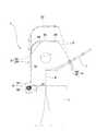
本実施形態に係る間接活線作業用具支持装置は、図1に示す如く、高所作業車(図示しない)のバケットCに取り付けられるもので、一方向に長手をなす長尺な索条10を巻き取る巻取ドラム200が所定の軸回りで回転可能に内装された装置本体20と、該装置本体20に連設されて巻取ドラム200から引き出された索条10をガイドする索条案内体30とを備えている。 As shown in FIG. 1, the indirect hot wire working tool support device according to the present embodiment is attached to a bucket C of an aerial work vehicle (not shown), and has a
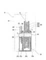
前記装置本体20は、高所作業車のバケットCを画定する側壁に対して取り付け可能に構成されている。本実施形態に係る装置本体20は、巻取ドラム200を内装する箱形のケーシング201を備えており、該ケーシング201の外面にバケットCの側壁に掛止させるフック202が取り付けられている。また、装置本体20は、図2に示す如く、巻取ドラム200で索条10を巻き取る方向に巻取ドラム200に回転力を付与する付勢手段203を備えている。 The apparatus
より具体的に説明すると、本実施形態に係る装置本体20は、一方向に長手をなした索条10を巻き取る巻取ドラム200と、該巻取ドラム200を軸支するフレーム205と、索条10を巻き取る方向に巻取ドラム200に回転力を付与する付勢手段203と、これらが内装されるケーシング201とを備えている。 More specifically, the apparatus
前記索条10は、ロープやチェーンが採用される。そして、索条10は、少なくとも外面に電気絶縁性を有していればよく、例えば、電気絶縁性を有する材料で外面が被覆されたものや、全体が電気絶縁性のある素材(例えば、樹脂や繊維)で形成されたものが採用される。本実施形態に係る索条10には、樹脂繊維を編み込んだ扁平状のロープが採用されている。より詳しくは、芳香族ポリアミド系樹脂製の繊維(ケブラー(登録商標))を断面扁平状になるように編み込んで作成されたロープが索条10として採用されている。そして、索条10の先端部には、間接活線作業用具Tを保持する保持手段40が設けられている(図1及び図3参照)。 The
本実施形態に係る巻取ドラム200は、プーリーの如く形成されている。すなわち、円柱状のドラム本体部200aと、該ドラム本体部200aの両端部から径方向外方延出した一対の鍔状部200b,200cとを備えている。本実施形態に係る間接活線作業用具支持装置1は、索条10に断面扁平状のロープを採用しているため、巻取ドラム200は、一対の鍔状部200b,200cの間隔がロープの幅(扁平方向と直交する方向の幅)に対応しており、一対の鍔状部200b,200c間でロープを一列に巻き取るようになっている。 The winding
そして、巻取ドラム200は、ドラム本体部200aの中心に軸体204が挿通されている。本実施形態において、前記軸体204は、巻取ドラム200に対して回り止め(本実施形態においてはキーKによる回り止め)がなされている。そして、軸体204は、フレーム205に取り付けられた軸受206,206によって巻取ドラム200の両側で軸支されている。これにより、巻取ドラム200は、軸体204とともに該軸体204の軸線周りで回転自在に設けられている。 The winding
また、本実施形態に係る間接活線作業用具支持装置1は、付勢手段203による付勢を巻取ドラム200に伝達するための伝達部材207を備えている。伝達部材207は、円板状に形成されており、巻取ドラム200と一体的になった前記軸体204の一端側が挿通されており、該軸体204に対して回り止め(本実施形態においてはキーKによる回り止め)がなされている。本実施形態においては、上述の如く、巻取ドラム200の両側で軸体204が軸受206,206を介して軸支されているため、前記伝達部材207は、軸体204における一方の軸受206から外方に延出した部分に固定されている。そして、前記伝達部材207は、付勢手段203の付勢(回転力)を受けるべく、付勢手段203が連結される第一連結部208が設けられている。 Further, the indirect hot wire working
前記フレーム205は、前記軸体204を軸支する一対の軸支部205a,205bと、付勢手段203が巻取ドラム200を付勢する際に生じる反力を受ける回転力対抗部205cとを備えている。一対の軸支部205a,205b、及び回転力対抗部205cは、何れもプレート状に形成されており、一対の軸支部205a,205bは、巻取ドラム200が介装可能な間隔をあけ、回転力対抗部205cは、一方の軸支部205aに対して、付勢手段203及び伝達部材207を介装可能な間隔をあけて配置されている。そして、本実施形態において、一対の軸支部205a,205b及び回転力対抗部205cは、それぞれの下端が共通のベース205dに連結されて一体的になっている。 The
一対の軸支部205a,205bのそれぞれには、上述の如く、軸体204を軸支する軸受206,206が装着されている。なお、言うまでもないが、各軸支部205a,205bの軸受206,206は、同心になるように配置されている。 As described above, the
前記回転力対抗部205cは、付勢手段203の付勢(回転力)の反力を受けるべく、付勢手段203が連結される第二連結部209が設けられている。なお、第一連結部208は、回転力対抗部205c側に設けられ、第二連結部209は一方の軸支部205a側に設けられている。 The rotational force
本実施形態に係る付勢手段203は、渦巻きバネ203で構成されており、中央に前記軸体204が遊挿されている。そして、渦巻きバネ203は、軸体204が遊挿された状態で、一端が第一連結部208に連結され、他端が第二連結部209に連結されている。これにより、巻取ドラム200を一方向(索条10を引き出す方向)に回転させると渦巻きバネ203が弾性変形し、その復元力によって巻取ドラム200に対して一方向とは反対側の他方向(索条10を巻き取る方向)の付勢力(回転力)を作用させるようになっている。 The biasing means 203 according to the present embodiment is constituted by a
前記ケーシング201は、上述の如く、巻取ドラム200、フレーム205、及び付勢手段203が内装されるもので箱状に形成されており、底部にフレーム205(ベース205d)が固定されている。そして、図3に示す如く、ケーシング201には、巻取ドラム200から引き出された索条10を外部に引き出すための引出口210(開口)が設けられている。本実施形態においては、ケーシング201の上部に引出口210が設けられている。 As described above, the
前記索条案内体30は、装置本体20から上方に向けて延びる第一案内部300と、該第一案内部300の上端に連設され、装置本体20がバケットCに取り付けられた状態で該バケットCに搭乗した作業者Wの頭よりも高い位置(図1参照)で前記第一案内部300と交差方向に延びる第二案内部301とを備えている。 The
本実施形態に係る索条案内体30は、パイプで構成されており、索条10を挿通可能な内径に設定されている。 The
より具体的に説明すると、前記第一案内部300は、索条10の幅方向の寸法よりも大きな内径に設定され、下端が装置本体20に連結された内筒体302と、該内筒体302に外嵌された外筒体303とで構成されている。そして、第一案内部300は、外筒体303が内筒体302に沿って上下方向にスライド可能になっている。また、本実施形態に係る第一案内部300は、内筒体302周り(上下方向に延びる軸線回り)で回転可能になっている。 More specifically, the
本実施形態に係る間接活線作業用具支持装置1は、図4に示す如く、スライド方向における複数位置で内筒体302に対して外筒体303を固定する固定手段304が設けられている。本実施形態に係る固定手段304は、内筒体302の外周面上に軸線方向に間隔をあけて形成された複数の環状溝304a…と、外筒体303内に出退可能に外筒体303に装備されたロックピン304bとで構成されており、ロックピン304bの先端部を何れか一つの環状溝304a…に嵌入させるようになっている。これにより、外筒体303は、縦方向の複数位置で固定可能とされつつ各固定位置で軸線を中心にして回転可能とされる。 As shown in FIG. 4, the indirect hot wire work
図3に戻り、本実施形態に係る索条案内体30は、索条10の幅方向寸法よりも大きな内径(内筒体302の外径よりも大きな内径)に設定された一本のパイプを曲げ加工することで、第一案内部300の外筒体303と第二案内部301の一部とが一体的に形成されている。かかるパイプは、電気絶縁性を有する素材で構成されており、本実施形態においてはグラスファイバーで形成されている。 Returning to FIG. 3, the
そして、本実施形態に係る索条案内体30は、上述の如く、第一案内部300(内筒体302)の下端が装置本体20(ケーシング201)に連結されており、巻取ドラム200から引き出した索条10が挿通されている。すなわち、索条案内体30の内筒体302は、ケーシング201の引出口210と内穴とが連通するようにケーシング201の上部に下端が連結されている。 And the
本実施形態に係る第二案内部301は、上述の如く、一部(後述する第二案内部本体305)が第一案内部300(外筒体303)と一体的に形成され、その先端に索条10の引き出しに伴って作用する下向きの力が大きくなったときに索条10の引き出しを停止するブレーキ機構306が設けられている。すなわち、本実施形態に係る第二案内部301は、第一案内部300に接続される第二案内部本体305と、該第二案内部本体305の先端に連結されたブレーキ機構306とで構成されている。 As described above, a part of the
前記第二案内部本体305は、上述の如く、グラスファイバー製のパイプで構成されており、これに伴ってパイプの先端側の内部に、該パイプと同心をなすように補強用の筒状部材307が内装されている。これに対し、ブレーキ機構306は、図5(a)及び図5(b)に示す如く、第二案内部本体305と同径のパイプで構成された索条挿通部308と、該索条挿通部308の一端に互いに対向するように延設された一対の延出部309a,309bと、該一対の延出部309a,309bの先端に延設された爪部310とを備えている。 As described above, the second guide portion
かかるブレーキ機構306は、一対の延出部309a,309bが第二案内部本体305の内部に挿入された状態で、横方向に延びる軸線周りで回転可能となるように第二案内部本体305(本実施形態においては筒状部材307)に枢着されている。本実施形態に係るブレーキ機構306は、第二案内部本体305内(穴の中央領域)に回転軸が存在しないように、一対の延出部309a,309bが第二案内部本体305に連結されている。すなわち、一対の延出部309a,309bは、第二案内部本体305(本実施形態においては筒状部材307)の内周面と対向する外面にピン状の軸部311が凸設されており、第二案内部本体305(本実施形態においては筒状部材307)の内周面に設けられた凹部又は穴内に軸部311が挿入されている。これにより、該ブレーキ機構306は、横方向に延びる軸線周りで回転(傾動)可能になっている。 The
そして、ブレーキ機構306は、常態で索条挿通部308が第二案内部本体305と連続した姿勢(索条挿通部308の中心線と第二案内部本体305の中心線とが連続した姿勢)になるように、該索条挿通部308を上方に向けて付勢する復帰用付勢手段(図示しない)が設けられている。なお、復帰用付勢手段は、捻りコイルバネ等のバネ材料が採用される。 The
そして、前記爪部310は、常態(索条挿通部308が第二案内部本体305と連続した正規の姿勢)で、回転中心(軸部311)の下方側に位置するように設けられている。すなわち、爪部310は、正規の姿勢で第二案内部本体305の中心よりも下方側に変位した位置に位置するように形成されている。そして、第一案内部300及び第二案内部301に挿通される索条10は、爪部310の上方側を通過するように索条挿通部308に挿通されている。 And the said nail | claw
これにより、本実施形態に係る間接活線作業用具支持装置1は、図5(b)に示す如く、索条10の引き出し力が下方側に向いて作用し、且つ、その引き出し力が復帰用付勢手段の付勢力に勝ったときに、索条挿通部308が軸部311を支点にして傾動し、これに伴って軸部311を支点にして回転する爪部310が第二案内部本体305(筒状部材307)の内周面とともに索条10を挟み込んで該索条10の引き出しを停止するようになっている。そして、下向きの力が復帰用付勢手段の付勢力よりも小さくなると、図5(a)に示す如く、索条挿通部308が正規の姿勢に復帰し、これに伴って爪部310が第二案内部本体305(筒状部材307)の内周面から離間する結果、索条10の挟み込みが解除される(索条10の引き出し或いは巻取ドラム200による巻き取りが可能となる)ようになっている。 Thereby, as shown in FIG.5 (b), the indirect hot wire work
図1に戻り、前記保持手段40は、間接活線作業用具Tを保持できれば種々態様のものを採用することができ、本実施形態においては、間接活線作業用具Tの基端部を挿通させる筒状の保持部材400と、保持部材400を縮径させる締付部材401とで構成されている。前記保持部材400は、外周に雄ねじ(図示しない)が形成されるとともに、一端から他端側に向けて延びるスリット(図示しない)が周方向に間隔をあけて二つ以上形成されている。これに対して、締付部材401は、筒状に形成され、内周に前記保持部材400の雄ねじと螺合する雌ねじ(図示しない)が形成されている。上記構成の保持手段40は、保持部材400に間接活線作業用具Tの基端部を挿通させた上で、締付部材401を保持部材400に螺合させることで、スリットの形成された部分が縮径し、間接活線作業用具Tを保持できるようになっている。 Returning to FIG. 1, various types of holding means 40 can be adopted as long as the holding means 40 can hold the indirect hot wire working tool T. In the present embodiment, the base end portion of the indirect hot wire working tool T is inserted. A cylindrical holding
本実施形態に係る間接活線作業用具支持装置1は、以上の通りであり、次に、該間接活線作業用具支持装置1の作動について説明する。 The indirect hot-wire work
本実施形態に係る間接活線作業用具支持装置1は、装置本体20を高所作業車のバケットCの側壁に取り付けた状態で、巻取ドラム200からの索条10が索条案内体30(第一案内部300及び第二案内部301)にガイドされてバケットCに搭乗する作業者Wの頭よりも高い位置に導かれた状態になり、該索条10の先端に設けられた保持手段40が索条案内体30の上端から吊り下げられた状態となる。 In the indirect hot wire work
ここで、作業者Wの身長差によって頭が索条案内体30の第二案内部301よりも高い位置にある場合や、作業者Wの頭から第二案内部301が離れすぎているような場合、索条案内体30(第一案内部300)を上下方向に伸縮させ、第二案内部301を作業者Wの頭上の適正な位置に配置する。すなわち、外筒体303のロックピン304bを内筒体302の環状溝304a…から抜いた上で、外筒体303を上下方向にスライドさせ、第二案内部301を適正な配置にし、その位置に対応する環状溝304a…内にロックピン304bを嵌入する(図4参照)。 Here, when the head is at a higher position than the
そして、作業者Wは、間接活線作業用具Tを保持させ易い位置まで保持手段40を移動させた上で、作業内容に応じた間接活線作業用具Tの基端部側(把持部側)を保持手段40に保持させる。 Then, the worker W moves the holding means 40 to a position where the indirect live line work tool T can be easily held, and then the base end side (gripping part side) of the indirect live line work tool T according to the work content. Is held by the holding means 40.
このとき、保持手段40の移動に伴って索条10に引っ張り力が作用し、巻取ドラム200から保持手段40の移動量に応じた長さの索条10が引き出される。また、このように索条10の引き出しに伴って、巻取ドラム200が回転すると、付勢手段203(渦巻きバネ203)の一端が軸体204周りで回転し、螺旋ピッチが狭まるように弾性変形して巻取ドラム200に索条10を巻き取る方向の回転力を付与することになる(図2参照)。 At this time, a pulling force acts on the
これにより、保持手段40に間接活線作業用具支持装置1を保持させるまでに作業者Wが誤って保持手段40を離すと、索条10に対する引っ張り力の作用が解除される結果、巻取ドラム200が付勢手段203の付勢によって回転し、引き出されていた索条10が該巻取ドラム200に巻き取られることになる。これに伴い、保持手段40は、索条案内体30の上端に向けて移動して常態の位置にまで戻ることになる。 As a result, if the operator W accidentally releases the holding means 40 before the holding means 40 holds the indirect hot-wire work
これに対し、保持手段40に間接活線作業用具Tを保持させた上で作業者Wが誤って保持手段40及び間接活線作業用具Tを離すと、付勢手段203の付勢力が間接活線作業用具Tの荷重に勝る場合においては、索条10に対する引っ張り力の作用が解除される結果、巻取ドラム200が付勢手段203の付勢によって回転し、引き出されていた索条10が該巻取ドラム200に巻き取られることになる。これに伴い、保持手段40及び間接活線作業用具Tは、索条案内体30の上端に向けて移動することになる。また、付勢手段203の付勢力が間接活線作業用具Tの荷重とバランスがとれている場合においては、巻取ドラム200がそのままの状態を維持することになり、間接活線作業用具Tは第二案内部301の先端から垂下する索条10を介して吊り下げられた状態で維持することになる。 On the other hand, if the worker W accidentally releases the holding means 40 and the indirect live wire work tool T after the holding means 40 holds the indirect live wire work tool T, the urging force of the urging means 203 is indirectly activated. In the case where the load of the wire work tool T is exceeded, the action of the pulling force on the
これに対し、索条10の引き出し易さを考慮して付勢手段203の付勢力を小さく設定していると、該付勢手段203の付勢力に対して間接活線作業用具Tの荷重が勝ることになり、間接活線作業用具支持装置1は、索条10を引き出しつつ下方に移動することになるが、付勢手段203の付勢が作用しているため、自由落下のような高速で移動することがなく、間接活線作業用具TがバケットCから地上に落下してしまうまでに索条10を手繰り寄せて間接活線作業用具Tを回収することができる。 On the other hand, if the biasing force of the biasing means 203 is set small in consideration of the easiness of pulling out the
本実施形態においては、上述の如く、第二案内部301にブレーキ機構306を設けているため、上述の如く、付勢手段203の付勢が小さい場合であっても間接活線作業用具Tが下方に向けて移動することはない。すなわち、作業者Wが誤って手を離したとき、索条10が第二案内部301の先端から真っすく下方に延びた状態で間接活線作業用具Tが吊り下げられることになるため、その真下に向けて作用する力(荷重)が索条挿通部308の先端に作用し、索条挿通部308が軸部311を支点にして下方に傾動する。そうすると、爪部310も軸部311を支点にして回転し、該爪部310の上方で挿通されていた索条10が爪部310によって上方に押され、爪部310が第二案内部本体305(筒状部材307)の内周面とともに索条10を挟み込むことになり、索条10の移動が規制されることになる。従って、付勢手段203の付勢力が間接活線作業用具Tの荷重に比して小さく設定されていたとしても、間接活線作業用具Tが落下することはない。 In the present embodiment, since the
そして、保持手段40に保持させた間接活線作用工具を作業者Wが操作すると、該間接活線作業用具Tの移動に伴って索条10が引っ張られて巻取ドラム200から引き出されるかあるいは、巻取ドラム200に巻き取られることになる。この時、付勢手段203によって巻取ドラム200に付与された回転力が、索条10に作用する力(引き出し力)に対抗し、保持手段40(保持された間接活線作業用具T)を索条案内体30の上端に向けて引き上げようとする力が作用するため、作業者Wが間接活線作業用具Tを操作するとき、該間接活線作業用具Tの荷重(下向きの力)が保持手段40を引き上げようとする力(上向きの力)と相殺される。従って、作業者Wは、間接活線作業用具Tの荷重を負担することなく作業を行うことができる。 Then, when the operator W operates the indirect hot wire working tool held by the holding means 40, the
また、本実施形態に係る間接活線作業用具支持装置1は、巻取ドラム200から索条10を引き出し可能に構成され、また、巻取ドラム200に巻き取り可能、すなわち、湾曲自在な索条10の先端に設けられた保持手段40に間接活線作業用具Tを保持させるようになっているため、間接活線作業用具Tを操作(移動)に対応して索条10が引き出されたり湾曲したりすることになる。また、本実施形態において、前記索条案内体30は、第一案内部300の軸線周りで回転可能に構成されるため、間接活線作業用具Tが第二案内部301の延出方向に対して交差方向に移動すると、索条案内体30が上下方向に延びる軸線回りで回転し、間接活線作業用具Tの操作(移動)に追従するように索条10の吊り下げ位置が横方向で位置変更する。これにより間接活線作業用具Tの操作性を高めることができる。 Further, the indirect hot wire working
従って、上記構成の間接活線作業用具支持装置1は、高所作業での間接活線作業用具Tの落下防止と作業者Wの作業負担の軽減とを図ることができる上に、間接活線作業用具Tの操作が阻害されることなく間接活線作業を行うことができる。 Therefore, the indirect hot-wire work
なお、本発明に係る間接活線作業用具支持装置は、上記実施形態に限定されるものではなく、本発明の要旨を逸脱しない範囲で、適宜変更し得ることは勿論のことである。 In addition, the indirect hot wire work tool support device according to the present invention is not limited to the above-described embodiment, and it is needless to say that the apparatus can be appropriately changed without departing from the gist of the present invention.
上記実施形態において、ブレーキ機構306を設けたが、これに限定されるものではなく、付勢手段203の付勢力で間接活線作業用具Tの荷重とのバランスを図るようにしてもよい。 In the above embodiment, the
上記実施形態において、索条10として扁平状のロープを採用したが、これに限定されるものではなく、例えば、断面円形状をなす一般的なロープであってもよい。また、索条10は、ロープに限定されるものでなく、チェーンであってもよい。すなわち、索条10は、一方向に長手をなした長尺なものであれば、種々態様のものを採用することができる。 In the said embodiment, although the flat rope was employ | adopted as the
上記実施形態において、索条案内体30をグラスファイバーで形成したが、これに限定されるものではなく、樹脂や金属製のものであってもよい。但し、索条案内体30を金属で構成する場合には、少なくとも外周面を絶縁処理する(例えば、電気絶縁性を有する材料でコーティングする)ことが好ましい。 In the said embodiment, although the
上記実施形態において、前記索条案内体30を第一案内部300の軸線周りで回転可能に構成するとともに、第一案内部300を上下方向で伸縮可能に構成したが、これに限定されるものではなく、例えば、索条案内体30を回転不能としつつ第一案内部300を上下方向で伸縮可能に構成してもよいし、索条案内体30を上下方向で延びる軸線周りで回転可能としつつ、第一案内部300を上下方向で伸縮不能に構成してもよい。また、索条案内体30を回転不能で且つ伸縮不能にしてもよい。 In the above embodiment, the
上記実施形態において、固定手段304を機械的に構成しているが、例えば、固定手段304としてのダンパー(オイルダンパーやガスダンパー等)を起立状態で配置し、該ダンパーの一端を外筒体303に連結し、該ガスダンパーの他端をケーシング201又は内筒体302の下端側に連結してもよい。このようにすれば、第一案内部300を伸縮させたときに、外筒体303を任意の位置で停止させることができる。 In the above embodiment, the fixing
また、保持手段40は、上記実施形態で説明したものに限定されるものではなく、例えば、保持手段40を二つに分割した分割体で構成し、該二つの分割体で間接活線作業用具Tの基端側を挟み込むことで、間接活線作業用具Tを保持(連結)できるようにしたものであってもよい。なお、二つの分割体で保持手段40を構成する場合、何れか一方の分割体に索条10を連結するか、二つの分割体の両方に索条10を連結すればよい。 Further, the holding means 40 is not limited to the one described in the above embodiment. For example, the holding means 40 is constituted by a divided body divided into two, and the indirect hot-line work tool is formed by the two divided bodies. It may be configured such that the indirect hot wire working tool T can be held (connected) by sandwiching the proximal end side of T. In addition, when comprising the holding means 40 with two division bodies, the
上記実施形態において、索条案内体30をパイプで構成し、索条10を索条案内体30内に挿通するようにしたが、これに限定されるものではなく、例えば、索条案内体30(第一案内部300及び第二案内部301)を、中実又は中空の棒体と、該棒体の長手方向に間隔をあけて配置された複数のガイドリングとで構成し、索条10をガイドリングに挿通して作業者Wの頭上にまで導く(ガイドする)ようにしてもよい。 In the said embodiment, although the
1…間接活線作業用具支持装置、10…索条、20…装置本体、30…索条案内体、40…保持手段、200…巻取ドラム、200a…ドラム本体部、200b,200c…鍔状部、201…ケーシング、202…フック、203…渦巻きバネ(付勢手段)、204…軸体、205…フレーム、205a,205b…軸支部、205c…回転力対抗部、205d…ベース、206,206…軸受、207…伝達部材、208…第一連結部、209…第二連結部、210…引出口、300…第一案内部、301…第二案内部、302…内筒体、303…外筒体、304…固定手段、304a…環状溝、304b…ロックピン、305…第二案内部本体、306…ブレーキ機構、307…筒状部材、308…索条挿通部、309a,309b…延出部、310…爪部、311…軸部、400…保持部材、401…締付部材、C…バケット、K…キー、T…間接活線作業用具、W…作業者 DESCRIPTION OF
Claims (3)
Translated fromJapanese間接活線作業用具支持装置。The indirect hot wire work tool support device according to claim 1, wherein the rope guide body is configured to be rotatable around an axis of the first guide portion.
Priority Applications (1)
| Application Number | Priority Date | Filing Date | Title |
|---|---|---|---|
| JP2009283103AJP5579427B2 (en) | 2009-12-14 | 2009-12-14 | Indirect hot wire work tool support device |
Applications Claiming Priority (1)
| Application Number | Priority Date | Filing Date | Title |
|---|---|---|---|
| JP2009283103AJP5579427B2 (en) | 2009-12-14 | 2009-12-14 | Indirect hot wire work tool support device |
Publications (2)
| Publication Number | Publication Date |
|---|---|
| JP2011125195Atrue JP2011125195A (en) | 2011-06-23 |
| JP5579427B2 JP5579427B2 (en) | 2014-08-27 |
Family
ID=44288507
Family Applications (1)
| Application Number | Title | Priority Date | Filing Date |
|---|---|---|---|
| JP2009283103AExpired - Fee RelatedJP5579427B2 (en) | 2009-12-14 | 2009-12-14 | Indirect hot wire work tool support device |
Country Status (1)
| Country | Link |
|---|---|
| JP (1) | JP5579427B2 (en) |
Cited By (211)
| Publication number | Priority date | Publication date | Assignee | Title |
|---|---|---|---|---|
| US8366709B2 (en) | 2004-09-21 | 2013-02-05 | Covidien Ag | Articulating bipolar electrosurgical instrument |
| US8430876B2 (en) | 2009-08-27 | 2013-04-30 | Tyco Healthcare Group Lp | Vessel sealer and divider with knife lockout |
| US8454602B2 (en) | 2009-05-07 | 2013-06-04 | Covidien Lp | Apparatus, system, and method for performing an electrosurgical procedure |
| US8523898B2 (en) | 2009-07-08 | 2013-09-03 | Covidien Lp | Endoscopic electrosurgical jaws with offset knife |
| US8540712B2 (en) | 2010-08-20 | 2013-09-24 | Covidien Lp | Surgical instrument configured for use with interchangeable hand grips |
| US8568444B2 (en) | 2008-10-03 | 2013-10-29 | Covidien Lp | Method of transferring rotational motion in an articulating surgical instrument |
| US8574230B2 (en) | 2009-09-03 | 2013-11-05 | Covidien Lp | Open vessel sealing instrument with pivot assembly |
| US8591506B2 (en) | 1998-10-23 | 2013-11-26 | Covidien Ag | Vessel sealing system |
| US8597296B2 (en) | 2003-11-17 | 2013-12-03 | Covidien Ag | Bipolar forceps having monopolar extension |
| US8628557B2 (en) | 2011-07-11 | 2014-01-14 | Covidien Lp | Surgical forceps |
| US8679140B2 (en) | 2012-05-30 | 2014-03-25 | Covidien Lp | Surgical clamping device with ratcheting grip lock |
| US8702737B2 (en) | 2011-08-08 | 2014-04-22 | Covidien Lp | Surgical forceps |
| US8702749B2 (en) | 2011-06-09 | 2014-04-22 | Covidien Lp | Lever latch assemblies for vessel sealer and divider |
| US8747434B2 (en) | 2012-02-20 | 2014-06-10 | Covidien Lp | Knife deployment mechanisms for surgical forceps |
| US8752264B2 (en) | 2012-03-06 | 2014-06-17 | Covidien Lp | Surgical tissue sealer |
| US8756785B2 (en) | 2011-09-29 | 2014-06-24 | Covidien Lp | Surgical instrument shafts and methods of manufacturing shafts for surgical instruments |
| US8764749B2 (en) | 2008-04-22 | 2014-07-01 | Covidien | Jaw closure detection system |
| US8852228B2 (en) | 2009-01-13 | 2014-10-07 | Covidien Lp | Apparatus, system, and method for performing an electrosurgical procedure |
| US8864753B2 (en) | 2011-12-13 | 2014-10-21 | Covidien Lp | Surgical Forceps Connected to Treatment Light Source |
| US8864795B2 (en) | 2011-10-03 | 2014-10-21 | Covidien Lp | Surgical forceps |
| US8887373B2 (en) | 2012-02-24 | 2014-11-18 | Covidien Lp | Vessel sealing instrument with reduced thermal spread and method of manufacture therefor |
| US8898888B2 (en) | 2009-09-28 | 2014-12-02 | Covidien Lp | System for manufacturing electrosurgical seal plates |
| US8920461B2 (en) | 2012-05-01 | 2014-12-30 | Covidien Lp | Surgical forceps with bifurcated flanged jaw components |
| US8939975B2 (en) | 2012-07-17 | 2015-01-27 | Covidien Lp | Gap control via overmold teeth and hard stops |
| US8961514B2 (en) | 2012-03-06 | 2015-02-24 | Covidien Lp | Articulating surgical apparatus |
| US8961515B2 (en) | 2011-09-28 | 2015-02-24 | Covidien Lp | Electrosurgical instrument |
| US8961513B2 (en) | 2012-01-25 | 2015-02-24 | Covidien Lp | Surgical tissue sealer |
| US8968310B2 (en) | 2011-11-30 | 2015-03-03 | Covidien Lp | Electrosurgical instrument with a knife blade lockout mechanism |
| US8968309B2 (en) | 2011-11-10 | 2015-03-03 | Covidien Lp | Surgical forceps |
| US8968313B2 (en) | 2012-06-12 | 2015-03-03 | Covidien Lp | Electrosurgical instrument with a knife blade stop |
| US8968308B2 (en) | 2011-10-20 | 2015-03-03 | Covidien Lp | Multi-circuit seal plates |
| US8968360B2 (en) | 2012-01-25 | 2015-03-03 | Covidien Lp | Surgical instrument with resilient driving member and related methods of use |
| US8968298B2 (en) | 2012-03-15 | 2015-03-03 | Covidien Lp | Electrosurgical instrument |
| US8968311B2 (en) | 2012-05-01 | 2015-03-03 | Covidien Lp | Surgical instrument with stamped double-flag jaws and actuation mechanism |
| US8968306B2 (en) | 2011-08-09 | 2015-03-03 | Covidien Lp | Surgical forceps |
| USD726910S1 (en) | 2013-08-07 | 2015-04-14 | Covidien Lp | Reusable forceps for open vessel sealer with mechanical cutter |
| US9011435B2 (en) | 2012-02-24 | 2015-04-21 | Covidien Lp | Method for manufacturing vessel sealing instrument with reduced thermal spread |
| US9011436B2 (en) | 2012-06-26 | 2015-04-21 | Covidien Lp | Double-length jaw system for electrosurgical instrument |
| US9023035B2 (en) | 2012-01-06 | 2015-05-05 | Covidien Lp | Monopolar pencil with integrated bipolar/ligasure tweezers |
| USD728786S1 (en) | 2013-05-03 | 2015-05-05 | Covidien Lp | Vessel sealer with mechanical cutter and pistol-grip-style trigger |
| US9024237B2 (en) | 2009-09-29 | 2015-05-05 | Covidien Lp | Material fusing apparatus, system and method of use |
| US9028493B2 (en) | 2009-09-18 | 2015-05-12 | Covidien Lp | In vivo attachable and detachable end effector assembly and laparoscopic surgical instrument and methods therefor |
| US9033981B2 (en) | 2008-12-10 | 2015-05-19 | Covidien Lp | Vessel sealer and divider |
| US9034009B2 (en) | 2012-05-01 | 2015-05-19 | Covidien Lp | Surgical forceps |
| US9039691B2 (en) | 2012-06-29 | 2015-05-26 | Covidien Lp | Surgical forceps |
| US9039731B2 (en) | 2012-05-08 | 2015-05-26 | Covidien Lp | Surgical forceps including blade safety mechanism |
| US9060780B2 (en) | 2011-09-29 | 2015-06-23 | Covidien Lp | Methods of manufacturing shafts for surgical instruments |
| US9072524B2 (en) | 2012-06-29 | 2015-07-07 | Covidien Lp | Surgical forceps |
| USD736920S1 (en) | 2013-08-07 | 2015-08-18 | Covidien Lp | Open vessel sealer with mechanical cutter |
| US9113909B2 (en) | 2011-09-01 | 2015-08-25 | Covidien Lp | Surgical vessel sealer and divider |
| US9113940B2 (en) | 2011-01-14 | 2015-08-25 | Covidien Lp | Trigger lockout and kickback mechanism for surgical instruments |
| US9113905B2 (en) | 2008-07-21 | 2015-08-25 | Covidien Lp | Variable resistor jaw |
| US9113906B2 (en) | 2010-01-22 | 2015-08-25 | Covidien Lp | Compact jaw including split pivot pin |
| US9113903B2 (en) | 2006-01-24 | 2015-08-25 | Covidien Lp | Endoscopic vessel sealer and divider for large tissue structures |
| US9113899B2 (en) | 2011-11-29 | 2015-08-25 | Covidien Lp | Coupling mechanisms for surgical instruments |
| US9113882B2 (en) | 2012-01-23 | 2015-08-25 | Covidien Lp | Method of manufacturing an electrosurgical instrument |
| US9113897B2 (en) | 2012-01-23 | 2015-08-25 | Covidien Lp | Partitioned surgical instrument |
| US9113901B2 (en) | 2012-05-14 | 2015-08-25 | Covidien Lp | Modular surgical instrument with contained electrical or mechanical systems |
| US9168052B2 (en) | 2010-06-02 | 2015-10-27 | Covidien Lp | Apparatus for performing an electrosurgical procedure |
| US9192432B2 (en) | 2012-05-29 | 2015-11-24 | Covidien Lp | Lever latch assemblies for surgical improvements |
| US9192421B2 (en) | 2012-07-24 | 2015-11-24 | Covidien Lp | Blade lockout mechanism for surgical forceps |
| US9192433B2 (en) | 2010-06-02 | 2015-11-24 | Covidien Lp | Apparatus for performing an electrosurgical procedure |
| USD744644S1 (en) | 2013-08-07 | 2015-12-01 | Covidien Lp | Disposable housing for open vessel sealer with mechanical cutter |
| US9204924B2 (en) | 2006-10-06 | 2015-12-08 | Covidien Lp | Endoscopic vessel sealer and divider having a flexible articulating shaft |
| US9259266B2 (en) | 2008-02-15 | 2016-02-16 | Covidien Lp | Method and system for sterilizing an electrosurgical instrument |
| US9259268B2 (en) | 2011-12-06 | 2016-02-16 | Covidien Lp | Vessel sealing using microwave energy |
| US9265565B2 (en) | 2011-11-29 | 2016-02-23 | Covidien Lp | Open vessel sealing instrument and method of manufacturing the same |
| US9265569B2 (en) | 2012-03-29 | 2016-02-23 | Covidien Lp | Method of manufacturing an electrosurgical forceps |
| US9301798B2 (en) | 2012-07-19 | 2016-04-05 | Covidien Lp | Surgical forceps including reposable end effector assemblies |
| US9318691B2 (en) | 2010-04-29 | 2016-04-19 | Covidien Lp | Method of constructing a jaw member for an end effector assembly |
| US9314295B2 (en) | 2011-10-20 | 2016-04-19 | Covidien Lp | Dissection scissors on surgical device |
| US9345534B2 (en) | 2010-10-04 | 2016-05-24 | Covidien Lp | Vessel sealing instrument |
| US9375262B2 (en) | 2013-02-27 | 2016-06-28 | Covidien Lp | Limited use medical devices |
| US9375260B2 (en) | 2010-04-12 | 2016-06-28 | Covidien Lp | Surgical instrument with non-contact electrical coupling |
| US9375267B2 (en) | 2010-06-02 | 2016-06-28 | Covidien Lp | Apparatus for performing an electrosurgical procedure |
| US9375282B2 (en) | 2012-03-26 | 2016-06-28 | Covidien Lp | Light energy sealing, cutting and sensing surgical device |
| US9375258B2 (en) | 2012-05-08 | 2016-06-28 | Covidien Lp | Surgical forceps |
| US9375256B2 (en) | 2013-02-05 | 2016-06-28 | Covidien Lp | Electrosurgical forceps |
| US9375205B2 (en) | 2012-11-15 | 2016-06-28 | Covidien Lp | Deployment mechanisms for surgical instruments |
| US9375259B2 (en) | 2012-10-24 | 2016-06-28 | Covidien Lp | Electrosurgical instrument including an adhesive applicator assembly |
| US9439717B2 (en) | 2013-08-13 | 2016-09-13 | Covidien Lp | Surgical forceps including thermal spread control |
| US9439711B2 (en) | 2012-10-02 | 2016-09-13 | Covidien Lp | Medical devices for thermally treating tissue |
| US9445865B2 (en) | 2013-09-16 | 2016-09-20 | Covidien Lp | Electrosurgical instrument with end-effector assembly including electrically-conductive, tissue-engaging surfaces and switchable bipolar electrodes |
| US9456863B2 (en) | 2013-03-11 | 2016-10-04 | Covidien Lp | Surgical instrument with switch activation control |
| US9468453B2 (en) | 2013-05-03 | 2016-10-18 | Covidien Lp | Endoscopic surgical forceps |
| US9486220B2 (en) | 2011-09-28 | 2016-11-08 | Covidien Lp | Surgical tissue occluding device |
| US9492223B2 (en) | 2010-06-02 | 2016-11-15 | Covidien Lp | Apparatus for performing an electrosurgical procedure |
| US9492221B2 (en) | 2011-10-20 | 2016-11-15 | Covidien Lp | Dissection scissors on surgical device |
| US9498281B2 (en) | 2012-11-27 | 2016-11-22 | Covidien Lp | Surgical apparatus |
| US9510891B2 (en) | 2012-06-26 | 2016-12-06 | Covidien Lp | Surgical instruments with structures to provide access for cleaning |
| US9526564B2 (en) | 2012-10-08 | 2016-12-27 | Covidien Lp | Electric stapler device |
| US9526567B2 (en) | 2011-05-16 | 2016-12-27 | Covidien Lp | Thread-like knife for tissue cutting |
| US9545262B2 (en) | 2010-06-02 | 2017-01-17 | Covidien Lp | Apparatus for performing an electrosurgical procedure |
| US9549749B2 (en) | 2012-10-08 | 2017-01-24 | Covidien Lp | Surgical forceps |
| US9554845B2 (en) | 2013-07-18 | 2017-01-31 | Covidien Lp | Surgical forceps for treating and cutting tissue |
| US9572529B2 (en) | 2012-10-31 | 2017-02-21 | Covidien Lp | Surgical devices and methods utilizing optical coherence tomography (OCT) to monitor and control tissue sealing |
| US9579145B2 (en) | 2005-09-30 | 2017-02-28 | Covidien Ag | Flexible endoscopic catheter with ligasure |
| US9622810B2 (en) | 2013-05-10 | 2017-04-18 | Covidien Lp | Surgical forceps |
| US9636169B2 (en) | 2011-09-19 | 2017-05-02 | Covidien Lp | Electrosurgical instrument |
| US9636168B2 (en) | 2012-08-09 | 2017-05-02 | Covidien Lp | Electrosurgical instrument including nested knife assembly |
| US9642671B2 (en) | 2013-09-30 | 2017-05-09 | Covidien Lp | Limited-use medical device |
| US9649151B2 (en) | 2013-05-31 | 2017-05-16 | Covidien Lp | End effector assemblies and methods of manufacturing end effector assemblies for treating and/or cutting tissue |
| US9655673B2 (en) | 2013-03-11 | 2017-05-23 | Covidien Lp | Surgical instrument |
| US9668807B2 (en) | 2012-05-01 | 2017-06-06 | Covidien Lp | Simplified spring load mechanism for delivering shaft force of a surgical instrument |
| US9668808B2 (en) | 2011-05-06 | 2017-06-06 | Covidien Lp | Bifurcated shaft for surgical instrument |
| US9681908B2 (en) | 2012-10-08 | 2017-06-20 | Covidien Lp | Jaw assemblies for electrosurgical instruments and methods of manufacturing jaw assemblies |
| US9687290B2 (en) | 2012-10-02 | 2017-06-27 | Covidien Lp | Energy-based medical devices |
| US9687295B2 (en) | 2014-04-17 | 2017-06-27 | Covidien Lp | Methods of manufacturing a pair of jaw members of an end-effector assembly for a surgical instrument |
| US9693816B2 (en) | 2012-01-30 | 2017-07-04 | Covidien Lp | Electrosurgical apparatus with integrated energy sensing at tissue site |
| US9713493B2 (en) | 2012-04-30 | 2017-07-25 | Covidien Lp | Method of switching energy modality on a cordless RF device |
| US9713491B2 (en) | 2013-02-19 | 2017-07-25 | Covidien Lp | Method for manufacturing an electrode assembly configured for use with an electrosurigcal instrument |
| US9717548B2 (en) | 2013-09-24 | 2017-08-01 | Covidien Lp | Electrode for use in a bipolar electrosurgical instrument |
| US9724116B2 (en) | 2009-10-06 | 2017-08-08 | Covidien Lp | Jaw, blade and gap manufacturing for surgical instruments with small jaws |
| US9770288B2 (en) | 2010-08-23 | 2017-09-26 | Covidien Lp | Method of manufacturing tissue sealing electrodes |
| US9770255B2 (en) | 2012-06-26 | 2017-09-26 | Covidien Lp | One-piece handle assembly |
| US9820765B2 (en) | 2012-05-01 | 2017-11-21 | Covidien Lp | Surgical instrument with stamped double-flange jaws |
| US9833285B2 (en) | 2012-07-17 | 2017-12-05 | Covidien Lp | Optical sealing device with cutting ability |
| US9839467B2 (en) | 2010-01-29 | 2017-12-12 | Covidien Lp | Surgical forceps capable of adjusting seal plate width based on vessel size |
| US9848935B2 (en) | 2015-05-27 | 2017-12-26 | Covidien Lp | Surgical instruments including components and features facilitating the assembly and manufacturing thereof |
| US9877777B2 (en) | 2014-09-17 | 2018-01-30 | Covidien Lp | Surgical instrument having a bipolar end effector assembly and a deployable monopolar assembly |
| US9877775B2 (en) | 2013-03-12 | 2018-01-30 | Covidien Lp | Electrosurgical instrument with a knife blade stop |
| US9918785B2 (en) | 2014-09-17 | 2018-03-20 | Covidien Lp | Deployment mechanisms for surgical instruments |
| US9924999B2 (en) | 2012-09-07 | 2018-03-27 | Covidien Lp | Instruments, systems and methods for sealing tissue structures |
| US9931158B2 (en) | 2014-09-17 | 2018-04-03 | Covidien Lp | Deployment mechanisms for surgical instruments |
| US9943357B2 (en) | 2013-09-16 | 2018-04-17 | Covidien Lp | Split electrode for use in a bipolar electrosurgical instrument |
| US9956022B2 (en) | 2015-05-27 | 2018-05-01 | Covidien Lp | Surgical forceps and methods of manufacturing the same |
| US9974602B2 (en) | 2015-05-27 | 2018-05-22 | Covidien Lp | Surgical instruments and devices and methods facilitating the manufacture of the same |
| US9974601B2 (en) | 2013-11-19 | 2018-05-22 | Covidien Lp | Vessel sealing instrument with suction system |
| USD819815S1 (en) | 2016-03-09 | 2018-06-05 | Covidien Lp | L-shaped blade trigger for an electrosurgical instrument |
| US9987076B2 (en) | 2014-09-17 | 2018-06-05 | Covidien Lp | Multi-function surgical instruments |
| US10058377B2 (en) | 2014-04-02 | 2018-08-28 | Covidien Lp | Electrosurgical devices including transverse electrode configurations |
| USD828554S1 (en) | 2016-03-09 | 2018-09-11 | Covidien Lp | Contoured blade trigger for an electrosurgical instrument |
| US10070916B2 (en) | 2013-03-11 | 2018-09-11 | Covidien Lp | Surgical instrument with system and method for springing open jaw members |
| US10080606B2 (en) | 2014-09-17 | 2018-09-25 | Covidien Lp | Method of forming a member of an end effector |
| US10080605B2 (en) | 2014-09-17 | 2018-09-25 | Covidien Lp | Deployment mechanisms for surgical instruments |
| US10130413B2 (en) | 2014-02-11 | 2018-11-20 | Covidien Lp | Temperature-sensing electrically-conductive tissue-contacting plate and methods of manufacturing same |
| US10154848B2 (en) | 2011-07-11 | 2018-12-18 | Covidien Lp | Stand alone energy-based tissue clips |
| US10154877B2 (en) | 2015-11-04 | 2018-12-18 | Covidien Lp | Endoscopic surgical instrument |
| US10172612B2 (en) | 2015-01-21 | 2019-01-08 | Covidien Lp | Surgical instruments with force applier and methods of use |
| US10172672B2 (en) | 2016-01-11 | 2019-01-08 | Covidien Lp | Jaw force control for electrosurgical forceps |
| US10206583B2 (en) | 2012-10-31 | 2019-02-19 | Covidien Lp | Surgical devices and methods utilizing optical coherence tomography (OCT) to monitor and control tissue sealing |
| US10206736B2 (en) | 2015-03-13 | 2019-02-19 | Covidien Lp | Surgical forceps with scalpel functionality |
| US10213221B2 (en) | 2015-10-28 | 2019-02-26 | Covidien Lp | Surgical instruments including cam surfaces |
| US10226269B2 (en) | 2015-05-27 | 2019-03-12 | Covidien Lp | Surgical forceps |
| US10231772B2 (en) | 2013-09-25 | 2019-03-19 | Covidien Lp | Wire retention unit for a surgical instrument |
| US10231776B2 (en) | 2014-01-29 | 2019-03-19 | Covidien Lp | Tissue sealing instrument with tissue-dissecting electrode |
| US10251696B2 (en) | 2001-04-06 | 2019-04-09 | Covidien Ag | Vessel sealer and divider with stop members |
| US10258360B2 (en) | 2014-09-25 | 2019-04-16 | Covidien Lp | Surgical instruments |
| US10265119B2 (en) | 2013-02-15 | 2019-04-23 | Covidien Lp | Electrosurgical forceps |
| US10278768B2 (en) | 2014-04-02 | 2019-05-07 | Covidien Lp | Electrosurgical devices including transverse electrode configurations |
| US10303641B2 (en) | 2014-05-07 | 2019-05-28 | Covidien Lp | Authentication and information system for reusable surgical instruments |
| USD854149S1 (en) | 2017-06-08 | 2019-07-16 | Covidien Lp | End effector for open vessel sealer |
| USD854684S1 (en) | 2017-06-08 | 2019-07-23 | Covidien Lp | Open vessel sealer with mechanical cutter |
| US10368945B2 (en) | 2012-07-17 | 2019-08-06 | Covidien Lp | Surgical instrument for energy-based tissue treatment |
| US10405874B2 (en) | 2013-08-13 | 2019-09-10 | Covidien Lp | Surgical instrument |
| USD859658S1 (en) | 2017-06-16 | 2019-09-10 | Covidien Lp | Vessel sealer for tonsillectomy |
| JP2019161778A (en)* | 2018-03-09 | 2019-09-19 | 中国電力株式会社 | Auxiliary tool for insulation operation bar |
| US10441305B2 (en) | 2016-08-18 | 2019-10-15 | Covidien Lp | Surgical forceps |
| US10441340B2 (en) | 2015-05-27 | 2019-10-15 | Covidien Lp | Surgical forceps |
| US10463422B2 (en) | 2014-12-18 | 2019-11-05 | Covidien Lp | Surgical instrument with stopper assembly |
| US10499975B2 (en) | 2013-08-07 | 2019-12-10 | Covidien Lp | Bipolar surgical instrument |
| US10512501B2 (en) | 2017-06-08 | 2019-12-24 | Covidien Lp | Electrosurgical apparatus |
| US10517665B2 (en) | 2016-07-14 | 2019-12-31 | Covidien Lp | Devices and methods for tissue sealing and mechanical clipping |
| US10537381B2 (en) | 2016-02-26 | 2020-01-21 | Covidien Lp | Surgical instrument having a bipolar end effector assembly and a deployable monopolar assembly |
| US10595933B2 (en) | 2015-04-24 | 2020-03-24 | Covidien Lp | Multifunctional vessel sealing and divider device |
| US10610289B2 (en) | 2013-09-25 | 2020-04-07 | Covidien Lp | Devices, systems, and methods for grasping, treating, and dividing tissue |
| US10631887B2 (en) | 2016-08-15 | 2020-04-28 | Covidien Lp | Electrosurgical forceps for video assisted thoracoscopic surgery and other surgical procedures |
| US10653475B2 (en) | 2017-06-08 | 2020-05-19 | Covidien Lp | Knife lockout for electrosurgical forceps |
| US10653476B2 (en) | 2015-03-12 | 2020-05-19 | Covidien Lp | Mapping vessels for resecting body tissue |
| US10660694B2 (en) | 2014-08-27 | 2020-05-26 | Covidien Lp | Vessel sealing instrument and switch assemblies thereof |
| US10695123B2 (en) | 2016-01-29 | 2020-06-30 | Covidien Lp | Surgical instrument with sensor |
| US10722292B2 (en) | 2013-05-31 | 2020-07-28 | Covidien Lp | Surgical device with an end-effector assembly and system for monitoring of tissue during a surgical procedure |
| US10722293B2 (en) | 2015-05-29 | 2020-07-28 | Covidien Lp | Surgical device with an end effector assembly and system for monitoring of tissue before and after a surgical procedure |
| US10758257B2 (en) | 2015-04-24 | 2020-09-01 | Covidien Lp | Vessel sealing device with fine dissection function |
| US10772674B2 (en) | 2012-11-15 | 2020-09-15 | Covidien Lp | Deployment mechanisms for surgical instruments |
| US10772642B2 (en) | 2016-08-18 | 2020-09-15 | Covidien Lp | Surgical forceps |
| US10780544B2 (en) | 2018-04-24 | 2020-09-22 | Covidien Lp | Systems and methods facilitating reprocessing of surgical instruments |
| US10813695B2 (en) | 2017-01-27 | 2020-10-27 | Covidien Lp | Reflectors for optical-based vessel sealing |
| US10820939B2 (en) | 2014-09-15 | 2020-11-03 | Covidien Lp | Vessel-sealing device including force-balance interface and electrosurgical system including same |
| US10828756B2 (en) | 2018-04-24 | 2020-11-10 | Covidien Lp | Disassembly methods facilitating reprocessing of multi-function surgical instruments |
| US10864003B2 (en) | 2016-02-05 | 2020-12-15 | Covidien Lp | Articulation assemblies for use with endoscopic surgical instruments |
| US10881445B2 (en) | 2017-02-09 | 2021-01-05 | Covidien Lp | Adapters, systems incorporating the same, and methods for providing an electrosurgical forceps with clip-applying functionality |
| US10881452B2 (en) | 2018-10-16 | 2021-01-05 | Covidien Lp | Method of assembling an end effector for a surgical instrument |
| US10966780B2 (en) | 2012-04-17 | 2021-04-06 | Covidien Lp | Electrosurgical instrument having a coated electrode |
| US10973567B2 (en) | 2017-05-12 | 2021-04-13 | Covidien Lp | Electrosurgical forceps for grasping, treating, and/or dividing tissue |
| US11033289B2 (en) | 2018-05-02 | 2021-06-15 | Covidien Lp | Jaw guard for surgical forceps |
| US11090109B2 (en) | 2014-02-11 | 2021-08-17 | Covidien Lp | Temperature-sensing electrically-conductive tissue-contacting plate configured for use in an electrosurgical jaw member, electrosurgical system including same, and methods of controlling vessel sealing using same |
| US11109930B2 (en) | 2018-06-08 | 2021-09-07 | Covidien Lp | Enhanced haptic feedback system |
| US11123132B2 (en) | 2018-04-09 | 2021-09-21 | Covidien Lp | Multi-function surgical instruments and assemblies therefor |
| US11147613B2 (en) | 2019-03-15 | 2021-10-19 | Covidien Lp | Surgical instrument with increased lever stroke |
| US11154348B2 (en) | 2017-08-29 | 2021-10-26 | Covidien Lp | Surgical instruments and methods of assembling surgical instruments |
| US11172980B2 (en) | 2017-05-12 | 2021-11-16 | Covidien Lp | Electrosurgical forceps for grasping, treating, and/or dividing tissue |
| US11207091B2 (en) | 2016-11-08 | 2021-12-28 | Covidien Lp | Surgical instrument for grasping, treating, and/or dividing tissue |
| US11229480B2 (en) | 2017-02-02 | 2022-01-25 | Covidien Lp | Latching mechanism for in-line activated electrosurgical device |
| US11246648B2 (en) | 2018-12-10 | 2022-02-15 | Covidien Lp | Surgical forceps with bilateral and unilateral jaw members |
| US11350982B2 (en) | 2018-12-05 | 2022-06-07 | Covidien Lp | Electrosurgical forceps |
| US11376062B2 (en) | 2018-10-12 | 2022-07-05 | Covidien Lp | Electrosurgical forceps |
| US11376030B2 (en) | 2020-02-10 | 2022-07-05 | Covidien Lp | Devices and methods facilitating the manufacture of surgical instruments |
| US11471211B2 (en) | 2018-10-12 | 2022-10-18 | Covidien Lp | Electrosurgical forceps |
| US11490916B2 (en) | 2019-03-29 | 2022-11-08 | Covidien Lp | Engagement features and methods for attaching a drive rod to a knife blade in an articulating surgical instrument |
| US11490917B2 (en) | 2019-03-29 | 2022-11-08 | Covidien Lp | Drive rod and knife blade for an articulating surgical instrument |
| US11523861B2 (en) | 2019-03-22 | 2022-12-13 | Covidien Lp | Methods for manufacturing a jaw assembly for an electrosurgical forceps |
| US11540872B2 (en) | 2017-03-13 | 2023-01-03 | Covidien Lp | Electrosurgical instrument with trigger driven cutting function |
| US11576696B2 (en) | 2019-03-29 | 2023-02-14 | Covidien Lp | Engagement features and methods for attaching a drive rod to a knife blade in an articulating surgical instrument |
| US11607267B2 (en) | 2019-06-10 | 2023-03-21 | Covidien Lp | Electrosurgical forceps |
| US11612403B2 (en) | 2018-10-03 | 2023-03-28 | Covidien Lp | Multi-function surgical transection instrument |
| US11617612B2 (en) | 2020-03-16 | 2023-04-04 | Covidien Lp | Forceps with linear trigger mechanism |
| US11844562B2 (en) | 2020-03-23 | 2023-12-19 | Covidien Lp | Electrosurgical forceps for grasping, treating, and/or dividing tissue |
| US11896291B2 (en) | 2018-07-02 | 2024-02-13 | Covidien Lp | Electrically-insulative shafts, methods of manufacturing electrically-insulative shafts, and energy-based surgical instruments incorporating electrically-insulative shafts |
| US12220159B2 (en) | 2019-03-15 | 2025-02-11 | Covidien Lp | Surgical instrument with eccentric cam |
| US12408970B2 (en) | 2020-04-02 | 2025-09-09 | Covidien Lp | Systems and methods for sealing and dissecting tissue using an electrosurgical forceps including a thermal cutting element |
Citations (1)
| Publication number | Priority date | Publication date | Assignee | Title |
|---|---|---|---|---|
| JPH0670409U (en)* | 1993-03-05 | 1994-09-30 | 東北電力株式会社 | Indirect live wire tool suspension device |
- 2009
- 2009-12-14JPJP2009283103Apatent/JP5579427B2/ennot_activeExpired - Fee Related
Patent Citations (1)
| Publication number | Priority date | Publication date | Assignee | Title |
|---|---|---|---|---|
| JPH0670409U (en)* | 1993-03-05 | 1994-09-30 | 東北電力株式会社 | Indirect live wire tool suspension device |
Cited By (423)
| Publication number | Priority date | Publication date | Assignee | Title |
|---|---|---|---|---|
| US9463067B2 (en) | 1998-10-23 | 2016-10-11 | Covidien Ag | Vessel sealing system |
| US9375271B2 (en) | 1998-10-23 | 2016-06-28 | Covidien Ag | Vessel sealing system |
| US9375270B2 (en) | 1998-10-23 | 2016-06-28 | Covidien Ag | Vessel sealing system |
| US8591506B2 (en) | 1998-10-23 | 2013-11-26 | Covidien Ag | Vessel sealing system |
| US10687887B2 (en) | 2001-04-06 | 2020-06-23 | Covidien Ag | Vessel sealer and divider |
| US10265121B2 (en) | 2001-04-06 | 2019-04-23 | Covidien Ag | Vessel sealer and divider |
| US10251696B2 (en) | 2001-04-06 | 2019-04-09 | Covidien Ag | Vessel sealer and divider with stop members |
| US10441350B2 (en) | 2003-11-17 | 2019-10-15 | Covidien Ag | Bipolar forceps having monopolar extension |
| US8597296B2 (en) | 2003-11-17 | 2013-12-03 | Covidien Ag | Bipolar forceps having monopolar extension |
| US8366709B2 (en) | 2004-09-21 | 2013-02-05 | Covidien Ag | Articulating bipolar electrosurgical instrument |
| US9579145B2 (en) | 2005-09-30 | 2017-02-28 | Covidien Ag | Flexible endoscopic catheter with ligasure |
| US9918782B2 (en) | 2006-01-24 | 2018-03-20 | Covidien Lp | Endoscopic vessel sealer and divider for large tissue structures |
| US9113903B2 (en) | 2006-01-24 | 2015-08-25 | Covidien Lp | Endoscopic vessel sealer and divider for large tissue structures |
| US9204924B2 (en) | 2006-10-06 | 2015-12-08 | Covidien Lp | Endoscopic vessel sealer and divider having a flexible articulating shaft |
| US9259266B2 (en) | 2008-02-15 | 2016-02-16 | Covidien Lp | Method and system for sterilizing an electrosurgical instrument |
| US8764749B2 (en) | 2008-04-22 | 2014-07-01 | Covidien | Jaw closure detection system |
| US10245104B2 (en) | 2008-04-22 | 2019-04-02 | Covidien Lp | Jaw closure detection system |
| US11497547B2 (en) | 2008-04-22 | 2022-11-15 | Covidien Lp | Jaw closure detection system |
| US9474570B2 (en) | 2008-04-22 | 2016-10-25 | Covidien Lp | Jaw closure detection system |
| US9247988B2 (en) | 2008-07-21 | 2016-02-02 | Covidien Lp | Variable resistor jaw |
| US9113905B2 (en) | 2008-07-21 | 2015-08-25 | Covidien Lp | Variable resistor jaw |
| US8568444B2 (en) | 2008-10-03 | 2013-10-29 | Covidien Lp | Method of transferring rotational motion in an articulating surgical instrument |
| US9033981B2 (en) | 2008-12-10 | 2015-05-19 | Covidien Lp | Vessel sealer and divider |
| US9655675B2 (en) | 2008-12-10 | 2017-05-23 | Covidien Lp | Vessel sealer and divider |
| US9655674B2 (en) | 2009-01-13 | 2017-05-23 | Covidien Lp | Apparatus, system and method for performing an electrosurgical procedure |
| US8852228B2 (en) | 2009-01-13 | 2014-10-07 | Covidien Lp | Apparatus, system, and method for performing an electrosurgical procedure |
| US9345535B2 (en) | 2009-05-07 | 2016-05-24 | Covidien Lp | Apparatus, system and method for performing an electrosurgical procedure |
| US10085794B2 (en) | 2009-05-07 | 2018-10-02 | Covidien Lp | Apparatus, system and method for performing an electrosurgical procedure |
| US8858554B2 (en) | 2009-05-07 | 2014-10-14 | Covidien Lp | Apparatus, system, and method for performing an electrosurgical procedure |
| US8454602B2 (en) | 2009-05-07 | 2013-06-04 | Covidien Lp | Apparatus, system, and method for performing an electrosurgical procedure |
| US9364247B2 (en) | 2009-07-08 | 2016-06-14 | Covidien Lp | Endoscopic electrosurgical jaws with offset knife |
| US8523898B2 (en) | 2009-07-08 | 2013-09-03 | Covidien Lp | Endoscopic electrosurgical jaws with offset knife |
| US8529566B2 (en) | 2009-08-27 | 2013-09-10 | Covidien Lp | Vessel sealer and divider with knife lockout |
| US8430876B2 (en) | 2009-08-27 | 2013-04-30 | Tyco Healthcare Group Lp | Vessel sealer and divider with knife lockout |
| US9113941B2 (en) | 2009-08-27 | 2015-08-25 | Covidien Lp | Vessel sealer and divider with knife lockout |
| USRE46570E1 (en) | 2009-09-03 | 2017-10-17 | Covidien Lp | Open vessel sealing instrument with pivot assembly |
| US8591511B2 (en) | 2009-09-03 | 2013-11-26 | Covidien Lp | Open vessel sealing instrument with pivot assembly |
| US8574230B2 (en) | 2009-09-03 | 2013-11-05 | Covidien Lp | Open vessel sealing instrument with pivot assembly |
| US9931131B2 (en) | 2009-09-18 | 2018-04-03 | Covidien Lp | In vivo attachable and detachable end effector assembly and laparoscopic surgical instrument and methods therefor |
| US9028493B2 (en) | 2009-09-18 | 2015-05-12 | Covidien Lp | In vivo attachable and detachable end effector assembly and laparoscopic surgical instrument and methods therefor |
| US9750561B2 (en) | 2009-09-28 | 2017-09-05 | Covidien Lp | System for manufacturing electrosurgical seal plates |
| US10188454B2 (en) | 2009-09-28 | 2019-01-29 | Covidien Lp | System for manufacturing electrosurgical seal plates |
| US11026741B2 (en) | 2009-09-28 | 2021-06-08 | Covidien Lp | Electrosurgical seal plates |
| US11490955B2 (en) | 2009-09-28 | 2022-11-08 | Covidien Lp | Electrosurgical seal plates |
| US8898888B2 (en) | 2009-09-28 | 2014-12-02 | Covidien Lp | System for manufacturing electrosurgical seal plates |
| US9265552B2 (en) | 2009-09-28 | 2016-02-23 | Covidien Lp | Method of manufacturing electrosurgical seal plates |
| US9024237B2 (en) | 2009-09-29 | 2015-05-05 | Covidien Lp | Material fusing apparatus, system and method of use |
| US10675046B2 (en) | 2009-10-06 | 2020-06-09 | Covidien Lp | Jaw, blade and gap manufacturing for surgical instruments with small jaws |
| US11622782B2 (en) | 2009-10-06 | 2023-04-11 | Covidien Lp | Jaw, blade and gap manufacturing for surgical instruments with small jaws |
| US9724116B2 (en) | 2009-10-06 | 2017-08-08 | Covidien Lp | Jaw, blade and gap manufacturing for surgical instruments with small jaws |
| US9113906B2 (en) | 2010-01-22 | 2015-08-25 | Covidien Lp | Compact jaw including split pivot pin |
| US12279806B2 (en) | 2010-01-22 | 2025-04-22 | Covidien Lp | Compact jaw including split pivot pin |
| US11638605B2 (en) | 2010-01-22 | 2023-05-02 | Covidien Lp | Compact jaw including split pivot pin |
| US10709494B2 (en) | 2010-01-22 | 2020-07-14 | Covidien Lp | Compact jaw including split pivot pin |
| US9839467B2 (en) | 2010-01-29 | 2017-12-12 | Covidien Lp | Surgical forceps capable of adjusting seal plate width based on vessel size |
| US9375260B2 (en) | 2010-04-12 | 2016-06-28 | Covidien Lp | Surgical instrument with non-contact electrical coupling |
| US10278770B2 (en) | 2010-04-12 | 2019-05-07 | Covidien Lp | Surgical instrument with non-contact electrical coupling |
| US9318691B2 (en) | 2010-04-29 | 2016-04-19 | Covidien Lp | Method of constructing a jaw member for an end effector assembly |
| US11557714B2 (en) | 2010-04-29 | 2023-01-17 | Covidien Lp | Method of constructing a jaw member for an end effector assembly |
| US10862021B2 (en) | 2010-04-29 | 2020-12-08 | Covidien Lp | Method of constructing a jaw member for an end effector assembly |
| US9918783B2 (en) | 2010-04-29 | 2018-03-20 | Covidien Lp | Method of constructing a jaw member for an end effector assembly |
| US9492223B2 (en) | 2010-06-02 | 2016-11-15 | Covidien Lp | Apparatus for performing an electrosurgical procedure |
| US9192433B2 (en) | 2010-06-02 | 2015-11-24 | Covidien Lp | Apparatus for performing an electrosurgical procedure |
| US9545262B2 (en) | 2010-06-02 | 2017-01-17 | Covidien Lp | Apparatus for performing an electrosurgical procedure |
| US11116565B2 (en) | 2010-06-02 | 2021-09-14 | Covidien Lp | Apparatus for performing an electrosurgical procedure |
| US11007006B2 (en) | 2010-06-02 | 2021-05-18 | Covidien Lp | Apparatus for performing an electrosurgical procedure |
| US9168052B2 (en) | 2010-06-02 | 2015-10-27 | Covidien Lp | Apparatus for performing an electrosurgical procedure |
| US10136940B2 (en) | 2010-06-02 | 2018-11-27 | Covidien Lp | Apparatus for performing an electrosurgical procedure |
| US9375267B2 (en) | 2010-06-02 | 2016-06-28 | Covidien Lp | Apparatus for performing an electrosurgical procedure |
| US10245101B2 (en) | 2010-06-02 | 2019-04-02 | Covidien Lp | Apparatus for performing an electrosurgical procedure |
| US10327838B2 (en) | 2010-06-02 | 2019-06-25 | Covidien Lp | Apparatus for performing an electrosurgical procedure |
| US8540712B2 (en) | 2010-08-20 | 2013-09-24 | Covidien Lp | Surgical instrument configured for use with interchangeable hand grips |
| US9770288B2 (en) | 2010-08-23 | 2017-09-26 | Covidien Lp | Method of manufacturing tissue sealing electrodes |
| US10716616B2 (en) | 2010-08-23 | 2020-07-21 | Covidien Lp | Method of manufacturing tissue sealing electrodes |
| US10245099B2 (en) | 2010-10-04 | 2019-04-02 | Covidien Lp | Vessel sealing instrument |
| US9345534B2 (en) | 2010-10-04 | 2016-05-24 | Covidien Lp | Vessel sealing instrument |
| US10383649B2 (en) | 2011-01-14 | 2019-08-20 | Covidien Lp | Trigger lockout and kickback mechanism for surgical instruments |
| US11660108B2 (en) | 2011-01-14 | 2023-05-30 | Covidien Lp | Trigger lockout and kickback mechanism for surgical instruments |
| US9113940B2 (en) | 2011-01-14 | 2015-08-25 | Covidien Lp | Trigger lockout and kickback mechanism for surgical instruments |
| US9668808B2 (en) | 2011-05-06 | 2017-06-06 | Covidien Lp | Bifurcated shaft for surgical instrument |
| US10039587B2 (en) | 2011-05-16 | 2018-08-07 | Covidien Lp | Thread-like knife for tissue cutting |
| US9526567B2 (en) | 2011-05-16 | 2016-12-27 | Covidien Lp | Thread-like knife for tissue cutting |
| US8702749B2 (en) | 2011-06-09 | 2014-04-22 | Covidien Lp | Lever latch assemblies for vessel sealer and divider |
| US9113937B2 (en) | 2011-07-11 | 2015-08-25 | Covidien Lp | Surgical forceps |
| US8628557B2 (en) | 2011-07-11 | 2014-01-14 | Covidien Lp | Surgical forceps |
| US10524874B2 (en) | 2011-07-11 | 2020-01-07 | Covidien Lp | Surgical forceps |
| US10154848B2 (en) | 2011-07-11 | 2018-12-18 | Covidien Lp | Stand alone energy-based tissue clips |
| US8702737B2 (en) | 2011-08-08 | 2014-04-22 | Covidien Lp | Surgical forceps |
| US9770253B2 (en) | 2011-08-09 | 2017-09-26 | Covidien Lp | Surgical forceps |
| US8968306B2 (en) | 2011-08-09 | 2015-03-03 | Covidien Lp | Surgical forceps |
| US9113909B2 (en) | 2011-09-01 | 2015-08-25 | Covidien Lp | Surgical vessel sealer and divider |
| US9636169B2 (en) | 2011-09-19 | 2017-05-02 | Covidien Lp | Electrosurgical instrument |
| US9186206B2 (en) | 2011-09-28 | 2015-11-17 | Covidien Lp | Electrosurgical instrument |
| US9375266B2 (en) | 2011-09-28 | 2016-06-28 | Covidien Lp | Electrosurgical instrument |
| US8961515B2 (en) | 2011-09-28 | 2015-02-24 | Covidien Lp | Electrosurgical instrument |
| US9486220B2 (en) | 2011-09-28 | 2016-11-08 | Covidien Lp | Surgical tissue occluding device |
| US8756785B2 (en) | 2011-09-29 | 2014-06-24 | Covidien Lp | Surgical instrument shafts and methods of manufacturing shafts for surgical instruments |
| US9795402B2 (en) | 2011-09-29 | 2017-10-24 | Covidien Lp | Surgical instrument shafts and methods of manufacturing shafts for surgical instruments |
| US9060780B2 (en) | 2011-09-29 | 2015-06-23 | Covidien Lp | Methods of manufacturing shafts for surgical instruments |
| US9717549B2 (en) | 2011-10-03 | 2017-08-01 | Covidien Lp | Surgical forceps |
| US9504519B2 (en) | 2011-10-03 | 2016-11-29 | Covidien Lp | Surgical forceps |
| US11523862B2 (en) | 2011-10-03 | 2022-12-13 | Covidien Lp | Surgical forceps |
| US10376306B2 (en) | 2011-10-03 | 2019-08-13 | Covidien Lp | Surgical forceps |
| US8864795B2 (en) | 2011-10-03 | 2014-10-21 | Covidien Lp | Surgical forceps |
| US9375264B2 (en) | 2011-10-20 | 2016-06-28 | Covidien Lp | Multi-circuit seal plates |
| US9717550B2 (en) | 2011-10-20 | 2017-08-01 | Covidien Lp | Multi-circuit seal plates |
| US10299851B2 (en) | 2011-10-20 | 2019-05-28 | Covidien Lp | Dissection scissors on surgical device |
| US9314295B2 (en) | 2011-10-20 | 2016-04-19 | Covidien Lp | Dissection scissors on surgical device |
| US9492221B2 (en) | 2011-10-20 | 2016-11-15 | Covidien Lp | Dissection scissors on surgical device |
| US8968308B2 (en) | 2011-10-20 | 2015-03-03 | Covidien Lp | Multi-circuit seal plates |
| US10993762B2 (en) | 2011-10-20 | 2021-05-04 | Covidien Lp | Dissection scissors on surgical device |
| US8968309B2 (en) | 2011-11-10 | 2015-03-03 | Covidien Lp | Surgical forceps |
| US9375245B2 (en) | 2011-11-10 | 2016-06-28 | Covidien Lp | Surgical forceps |
| US9168088B2 (en) | 2011-11-10 | 2015-10-27 | Covidien Lp | Surgical forceps |
| US9113899B2 (en) | 2011-11-29 | 2015-08-25 | Covidien Lp | Coupling mechanisms for surgical instruments |
| US9554844B2 (en) | 2011-11-29 | 2017-01-31 | Covidien Lp | Open vessel sealing instrument and method of manufacturing the same |
| US9265565B2 (en) | 2011-11-29 | 2016-02-23 | Covidien Lp | Open vessel sealing instrument and method of manufacturing the same |
| US9750519B2 (en) | 2011-11-29 | 2017-09-05 | Covidien Lp | Coupling mechanisms for surgical instruments |
| US8968310B2 (en) | 2011-11-30 | 2015-03-03 | Covidien Lp | Electrosurgical instrument with a knife blade lockout mechanism |
| US10595932B2 (en) | 2011-11-30 | 2020-03-24 | Covidien Lp | Electrosurgical instrument with a knife blade lockout mechanism |
| US9610116B2 (en) | 2011-11-30 | 2017-04-04 | Covidien Lp | Electrosurgical instrument with a knife blade lockout mechanism |
| US9259268B2 (en) | 2011-12-06 | 2016-02-16 | Covidien Lp | Vessel sealing using microwave energy |
| US10390855B2 (en) | 2011-12-13 | 2019-08-27 | Covidien Lp | Surgical forceps |
| US8864753B2 (en) | 2011-12-13 | 2014-10-21 | Covidien Lp | Surgical Forceps Connected to Treatment Light Source |
| US9358069B2 (en) | 2011-12-13 | 2016-06-07 | Covidien Lp | Surgical forceps |
| US9539049B2 (en) | 2012-01-06 | 2017-01-10 | Covidien Lp | Monopolar pencil with integrated bipolar/ligasure tweezers |
| US9023035B2 (en) | 2012-01-06 | 2015-05-05 | Covidien Lp | Monopolar pencil with integrated bipolar/ligasure tweezers |
| US9918777B2 (en) | 2012-01-23 | 2018-03-20 | Covidien Lp | Partitioned surgical instrument |
| US9113882B2 (en) | 2012-01-23 | 2015-08-25 | Covidien Lp | Method of manufacturing an electrosurgical instrument |
| US11007000B2 (en) | 2012-01-23 | 2021-05-18 | Covidien Lp | Partitioned surgical instrument |
| US9113897B2 (en) | 2012-01-23 | 2015-08-25 | Covidien Lp | Partitioned surgical instrument |
| US11324545B2 (en) | 2012-01-25 | 2022-05-10 | Covidien Lp | Surgical instrument with resilient driving member and related methods of use |
| US10639095B2 (en) | 2012-01-25 | 2020-05-05 | Covidien Lp | Surgical instrument with resilient driving member and related methods of use |
| US12114913B2 (en) | 2012-01-25 | 2024-10-15 | Covidien Lp | Surgical instrument with resilient driving member and related methods of use |
| US8961513B2 (en) | 2012-01-25 | 2015-02-24 | Covidien Lp | Surgical tissue sealer |
| US9504514B2 (en) | 2012-01-25 | 2016-11-29 | Covidien Lp | Surgical instrument with resilient driving member and related methods of use |
| US9974605B2 (en) | 2012-01-25 | 2018-05-22 | Covidien Lp | Surgical instrument with resilient driving member and related methods of use |
| US8968360B2 (en) | 2012-01-25 | 2015-03-03 | Covidien Lp | Surgical instrument with resilient driving member and related methods of use |
| US9693816B2 (en) | 2012-01-30 | 2017-07-04 | Covidien Lp | Electrosurgical apparatus with integrated energy sensing at tissue site |
| US9867658B2 (en) | 2012-02-20 | 2018-01-16 | Covidien Lp | Knife deployment mechanisms for surgical forceps |
| US8747434B2 (en) | 2012-02-20 | 2014-06-10 | Covidien Lp | Knife deployment mechanisms for surgical forceps |
| US10639094B2 (en) | 2012-02-20 | 2020-05-05 | Covidien Lp | Knife deployment mechanisms for surgical forceps |
| US9084608B2 (en) | 2012-02-20 | 2015-07-21 | Covidien Lp | Knife deployment mechanisms for surgical forceps |
| US9468491B2 (en) | 2012-02-24 | 2016-10-18 | Covidien Lp | Vessel sealing instrument with reduced thermal spread and method of manufacture therefor |
| US8887373B2 (en) | 2012-02-24 | 2014-11-18 | Covidien Lp | Vessel sealing instrument with reduced thermal spread and method of manufacture therefor |
| US9011435B2 (en) | 2012-02-24 | 2015-04-21 | Covidien Lp | Method for manufacturing vessel sealing instrument with reduced thermal spread |
| US9161806B2 (en) | 2012-02-24 | 2015-10-20 | Covidien Lp | Vessel sealing instrument with reduced thermal spread and method of manufacture therefor |
| US9204919B2 (en) | 2012-02-24 | 2015-12-08 | Covidien Lp | Vessel sealing instrument with reduced thermal spread and method of manufacturing therefor |
| US9867659B2 (en) | 2012-02-24 | 2018-01-16 | Covidien Lp | Vessel sealing instrument with reduced thermal spread and method of manufacture therefor |
| US9211657B2 (en) | 2012-03-06 | 2015-12-15 | Covidien Lp | Surgical tissue sealer |
| US10327834B2 (en) | 2012-03-06 | 2019-06-25 | Covidien Lp | Surgical tissue sealer |
| US9308012B2 (en) | 2012-03-06 | 2016-04-12 | Covidien Lp | Articulating surgical apparatus |
| US8752264B2 (en) | 2012-03-06 | 2014-06-17 | Covidien Lp | Surgical tissue sealer |
| US8961514B2 (en) | 2012-03-06 | 2015-02-24 | Covidien Lp | Articulating surgical apparatus |
| US8968298B2 (en) | 2012-03-15 | 2015-03-03 | Covidien Lp | Electrosurgical instrument |
| US9610121B2 (en) | 2012-03-26 | 2017-04-04 | Covidien Lp | Light energy sealing, cutting and sensing surgical device |
| US10806514B2 (en) | 2012-03-26 | 2020-10-20 | Covidien Lp | Light energy sealing, cutting and sensing surgical device |
| US10806515B2 (en) | 2012-03-26 | 2020-10-20 | Covidien Lp | Light energy sealing, cutting, and sensing surgical device |
| US9925008B2 (en) | 2012-03-26 | 2018-03-27 | Covidien Lp | Light energy sealing, cutting and sensing surgical device |
| US9375282B2 (en) | 2012-03-26 | 2016-06-28 | Covidien Lp | Light energy sealing, cutting and sensing surgical device |
| US11819270B2 (en) | 2012-03-26 | 2023-11-21 | Covidien Lp | Light energy sealing, cutting and sensing surgical device |
| US10342597B2 (en) | 2012-03-29 | 2019-07-09 | Covidien Lp | Electrosurgical forceps jaw member and seal plate |
| US9265569B2 (en) | 2012-03-29 | 2016-02-23 | Covidien Lp | Method of manufacturing an electrosurgical forceps |
| US11707313B2 (en) | 2012-03-29 | 2023-07-25 | Covidien Lp | Electrosurgical forceps and method of manufacturing the same |
| US10966780B2 (en) | 2012-04-17 | 2021-04-06 | Covidien Lp | Electrosurgical instrument having a coated electrode |
| US9713493B2 (en) | 2012-04-30 | 2017-07-25 | Covidien Lp | Method of switching energy modality on a cordless RF device |
| US9034009B2 (en) | 2012-05-01 | 2015-05-19 | Covidien Lp | Surgical forceps |
| US11219482B2 (en) | 2012-05-01 | 2022-01-11 | Covidien Lp | Surgical instrument with stamped double-flange jaws and actuation mechanism |
| US9956030B2 (en) | 2012-05-01 | 2018-05-01 | Covidien Lp | Electrosurgical forceps with stamped double-flange jaws and u-shaped drive actuation mechanism |
| US12059166B2 (en) | 2012-05-01 | 2024-08-13 | Covidien Lp | Surgical instrument for treating tissue |
| US9345536B2 (en) | 2012-05-01 | 2016-05-24 | Covidien Lp | Surgical forceps with bifurcated flanged jaw components |
| US9820765B2 (en) | 2012-05-01 | 2017-11-21 | Covidien Lp | Surgical instrument with stamped double-flange jaws |
| US9265571B2 (en) | 2012-05-01 | 2016-02-23 | Covidien Lp | Surgical forceps |
| US10588651B2 (en) | 2012-05-01 | 2020-03-17 | Covidien Lp | Surgical instrument with stamped double-flange jaws |
| US11672592B2 (en) | 2012-05-01 | 2023-06-13 | Covidien Lp | Electrosurgical instrument |
| US9861378B2 (en) | 2012-05-01 | 2018-01-09 | Covidien Lp | Surgical instrument with stamped double-flange jaws |
| US10271897B2 (en) | 2012-05-01 | 2019-04-30 | Covidien Lp | Surgical instrument with stamped double-flange jaws and actuation mechanism |
| US8920461B2 (en) | 2012-05-01 | 2014-12-30 | Covidien Lp | Surgical forceps with bifurcated flanged jaw components |
| US9668807B2 (en) | 2012-05-01 | 2017-06-06 | Covidien Lp | Simplified spring load mechanism for delivering shaft force of a surgical instrument |
| US8968311B2 (en) | 2012-05-01 | 2015-03-03 | Covidien Lp | Surgical instrument with stamped double-flag jaws and actuation mechanism |
| US9375263B2 (en) | 2012-05-01 | 2016-06-28 | Covidien Lp | Surgical instrument with stamped double-flange jaws and actuation mechanism |
| US9375258B2 (en) | 2012-05-08 | 2016-06-28 | Covidien Lp | Surgical forceps |
| US9039731B2 (en) | 2012-05-08 | 2015-05-26 | Covidien Lp | Surgical forceps including blade safety mechanism |
| US9743976B2 (en) | 2012-05-08 | 2017-08-29 | Covidien Lp | Surgical forceps |
| US9668810B2 (en) | 2012-05-14 | 2017-06-06 | Covidien Lp | Modular surgical instrument with contained electrical or mechanical systems |
| US9113901B2 (en) | 2012-05-14 | 2015-08-25 | Covidien Lp | Modular surgical instrument with contained electrical or mechanical systems |
| US10117709B2 (en) | 2012-05-14 | 2018-11-06 | Covidien Lp | Modular surgical instruments with contained electrical or mechanical systems |
| US9192432B2 (en) | 2012-05-29 | 2015-11-24 | Covidien Lp | Lever latch assemblies for surgical improvements |
| US9974604B2 (en) | 2012-05-29 | 2018-05-22 | Covidien Lp | Lever latch assemblies for surgical instruments |
| US8679140B2 (en) | 2012-05-30 | 2014-03-25 | Covidien Lp | Surgical clamping device with ratcheting grip lock |
| US8968313B2 (en) | 2012-06-12 | 2015-03-03 | Covidien Lp | Electrosurgical instrument with a knife blade stop |
| US9314297B2 (en) | 2012-06-12 | 2016-04-19 | Covidien Lp | Electrosurgical instrument with a knife blade stop |
| US9011436B2 (en) | 2012-06-26 | 2015-04-21 | Covidien Lp | Double-length jaw system for electrosurgical instrument |
| US10588686B2 (en) | 2012-06-26 | 2020-03-17 | Covidien Lp | Surgical instruments with structures to provide access for cleaning |
| US9510891B2 (en) | 2012-06-26 | 2016-12-06 | Covidien Lp | Surgical instruments with structures to provide access for cleaning |
| US9770255B2 (en) | 2012-06-26 | 2017-09-26 | Covidien Lp | One-piece handle assembly |
| US9333028B2 (en) | 2012-06-26 | 2016-05-10 | Covidien Lp | Double-length jaw system for electrosurgical instrument |
| US10709496B2 (en) | 2012-06-29 | 2020-07-14 | Covidien Lp | Surgical forceps |
| US9649152B2 (en) | 2012-06-29 | 2017-05-16 | Covidien Lp | Surgical forceps |
| US9072524B2 (en) | 2012-06-29 | 2015-07-07 | Covidien Lp | Surgical forceps |
| US9358028B2 (en) | 2012-06-29 | 2016-06-07 | Covidien Lp | Surgical forceps |
| US9039691B2 (en) | 2012-06-29 | 2015-05-26 | Covidien Lp | Surgical forceps |
| US9918784B2 (en) | 2012-06-29 | 2018-03-20 | Covidien Lp | Surgical forceps |
| US9833285B2 (en) | 2012-07-17 | 2017-12-05 | Covidien Lp | Optical sealing device with cutting ability |
| US10702332B2 (en) | 2012-07-17 | 2020-07-07 | Covidien Lp | Gap control via overmold teeth and hard stops |
| US8939975B2 (en) | 2012-07-17 | 2015-01-27 | Covidien Lp | Gap control via overmold teeth and hard stops |
| US11490959B2 (en) | 2012-07-17 | 2022-11-08 | Covidien Lp | Surgical instrument for energy-based tissue treatment |
| US10368945B2 (en) | 2012-07-17 | 2019-08-06 | Covidien Lp | Surgical instrument for energy-based tissue treatment |
| US9468490B2 (en) | 2012-07-17 | 2016-10-18 | Covidien Lp | Gap control via overmold teeth and hard stops |
| US9192434B2 (en) | 2012-07-17 | 2015-11-24 | Covidien Lp | Gap control via overmold teeth and hard stops |
| US12336749B2 (en) | 2012-07-17 | 2025-06-24 | Covidien Lp | Gap control via overmold teeth and hard stops |
| US11490954B2 (en) | 2012-07-17 | 2022-11-08 | Covidien Lp | Gap control via overmold teeth and hard stops |
| US9931159B2 (en) | 2012-07-17 | 2018-04-03 | Covidien Lp | Gap control via overmold teeth and hard stops |
| US11596465B2 (en) | 2012-07-19 | 2023-03-07 | Covidien Lp | Surgical forceps including reposable end effector assemblies |
| US10413353B2 (en) | 2012-07-19 | 2019-09-17 | Covidien Lp | Surgical forceps including reposable end effector assemblies |
| US9301798B2 (en) | 2012-07-19 | 2016-04-05 | Covidien Lp | Surgical forceps including reposable end effector assemblies |
| US9192421B2 (en) | 2012-07-24 | 2015-11-24 | Covidien Lp | Blade lockout mechanism for surgical forceps |
| US9498280B2 (en) | 2012-07-24 | 2016-11-22 | Covidien Lp | Blade lockout mechanism for surgical forceps |
| US9636168B2 (en) | 2012-08-09 | 2017-05-02 | Covidien Lp | Electrosurgical instrument including nested knife assembly |
| US10098690B2 (en) | 2012-09-07 | 2018-10-16 | Covidien Lp | Instruments, systems, and methods for sealing tissue structures |
| US9924999B2 (en) | 2012-09-07 | 2018-03-27 | Covidien Lp | Instruments, systems and methods for sealing tissue structures |
| US9439711B2 (en) | 2012-10-02 | 2016-09-13 | Covidien Lp | Medical devices for thermally treating tissue |
| US10154872B2 (en) | 2012-10-02 | 2018-12-18 | Covidien Lp | Medical devices for thermally treating tissue |
| US10595926B2 (en) | 2012-10-02 | 2020-03-24 | Covidien Lp | Energy-based medical devices |
| US9687290B2 (en) | 2012-10-02 | 2017-06-27 | Covidien Lp | Energy-based medical devices |
| US9681908B2 (en) | 2012-10-08 | 2017-06-20 | Covidien Lp | Jaw assemblies for electrosurgical instruments and methods of manufacturing jaw assemblies |
| US11033320B2 (en) | 2012-10-08 | 2021-06-15 | Covidien Lp | Jaw assemblies for electrosurgical instruments and methods of manufacturing jaw assemblies |
| US10548658B2 (en) | 2012-10-08 | 2020-02-04 | Covidien Lp | Electric stapler device |
| US9526564B2 (en) | 2012-10-08 | 2016-12-27 | Covidien Lp | Electric stapler device |
| US11207129B2 (en) | 2012-10-08 | 2021-12-28 | Covidien Lp | Electric stapler device |
| US11253280B2 (en) | 2012-10-08 | 2022-02-22 | Covidien Lp | Surgical forceps |
| US10314639B2 (en) | 2012-10-08 | 2019-06-11 | Covidien Lp | Jaw assemblies for electrosurgical instruments and methods of manufacturing jaw assemblies |
| US9549749B2 (en) | 2012-10-08 | 2017-01-24 | Covidien Lp | Surgical forceps |
| US10441303B2 (en) | 2012-10-08 | 2019-10-15 | Covidien Lp | Surgical forceps |
| US12213720B2 (en) | 2012-10-08 | 2025-02-04 | Covidien Lp | Jaw assemblies for electrosurgical instruments and methods of manufacturing jaw assemblies |
| US10245102B2 (en) | 2012-10-24 | 2019-04-02 | Covidien Lp | Electrosurgical instrument including an adhesive applicator assembly |
| US9375259B2 (en) | 2012-10-24 | 2016-06-28 | Covidien Lp | Electrosurgical instrument including an adhesive applicator assembly |
| US10206583B2 (en) | 2012-10-31 | 2019-02-19 | Covidien Lp | Surgical devices and methods utilizing optical coherence tomography (OCT) to monitor and control tissue sealing |
| US11103135B2 (en) | 2012-10-31 | 2021-08-31 | Covidien Lp | Surgical devices and methods utilizing optical coherence tomography (OCT) to monitor and control tissue sealing |
| US9572529B2 (en) | 2012-10-31 | 2017-02-21 | Covidien Lp | Surgical devices and methods utilizing optical coherence tomography (OCT) to monitor and control tissue sealing |
| US10499847B2 (en) | 2012-10-31 | 2019-12-10 | Covidien Lp | Surgical devices and methods utilizing optical coherence tomography (OCT) to monitor and control tissue sealing |
| US11647907B2 (en) | 2012-10-31 | 2023-05-16 | Covidien Lp | Surgical devices and methods utilizing optical coherence tomography (OCT) to monitor and control tissue sealing |
| US11864822B2 (en) | 2012-11-15 | 2024-01-09 | Covidien Lp | Deployment mechanisms for surgical instruments |
| US10751112B2 (en) | 2012-11-15 | 2020-08-25 | Covidien Lp | Deployment mechanisms for surgical instruments |
| US9375205B2 (en) | 2012-11-15 | 2016-06-28 | Covidien Lp | Deployment mechanisms for surgical instruments |
| US12048475B2 (en) | 2012-11-15 | 2024-07-30 | Covidien Lp | Deployment mechanism for surgical instruments |
| US10772674B2 (en) | 2012-11-15 | 2020-09-15 | Covidien Lp | Deployment mechanisms for surgical instruments |
| US11172952B2 (en) | 2012-11-27 | 2021-11-16 | Covidien Lp | Surgical apparatus |
| US9498281B2 (en) | 2012-11-27 | 2016-11-22 | Covidien Lp | Surgical apparatus |
| US9375256B2 (en) | 2013-02-05 | 2016-06-28 | Covidien Lp | Electrosurgical forceps |
| US10299853B2 (en) | 2013-02-05 | 2019-05-28 | Covidien Lp | Electrosurgical forceps |
| US10265119B2 (en) | 2013-02-15 | 2019-04-23 | Covidien Lp | Electrosurgical forceps |
| US9713491B2 (en) | 2013-02-19 | 2017-07-25 | Covidien Lp | Method for manufacturing an electrode assembly configured for use with an electrosurigcal instrument |
| US10806508B2 (en) | 2013-02-19 | 2020-10-20 | Covidien Lp | Method for manufacturing an electrode assembly configured for use with an electrosurgical instrument |
| US9375262B2 (en) | 2013-02-27 | 2016-06-28 | Covidien Lp | Limited use medical devices |
| US10335228B2 (en) | 2013-03-11 | 2019-07-02 | Covidien Lp | Surgical instrument with switch activation control |
| US11090111B2 (en) | 2013-03-11 | 2021-08-17 | Covidien Lp | Surgical instrument with switch activation control |
| US10687886B2 (en) | 2013-03-11 | 2020-06-23 | Covidien Lp | Surgical instrument |
| US9456863B2 (en) | 2013-03-11 | 2016-10-04 | Covidien Lp | Surgical instrument with switch activation control |
| US9655673B2 (en) | 2013-03-11 | 2017-05-23 | Covidien Lp | Surgical instrument |
| US12048476B2 (en) | 2013-03-11 | 2024-07-30 | Covidien Lp | Surgical instrument with switch activation control |
| US11207128B2 (en) | 2013-03-11 | 2021-12-28 | Covidien Lp | Surgical instrument with system and method for springing open jaw members |
| US12011208B2 (en) | 2013-03-11 | 2024-06-18 | Covidien Lp | Surgical instrument |
| US11974802B2 (en) | 2013-03-11 | 2024-05-07 | Covidien Lp | Surgical instrument with system and method for springing open jaw members |
| US10070916B2 (en) | 2013-03-11 | 2018-09-11 | Covidien Lp | Surgical instrument with system and method for springing open jaw members |
| US9877775B2 (en) | 2013-03-12 | 2018-01-30 | Covidien Lp | Electrosurgical instrument with a knife blade stop |
| USD728786S1 (en) | 2013-05-03 | 2015-05-05 | Covidien Lp | Vessel sealer with mechanical cutter and pistol-grip-style trigger |
| US9468453B2 (en) | 2013-05-03 | 2016-10-18 | Covidien Lp | Endoscopic surgical forceps |
| US9622810B2 (en) | 2013-05-10 | 2017-04-18 | Covidien Lp | Surgical forceps |
| US10792090B2 (en) | 2013-05-10 | 2020-10-06 | Covidien Lp | Surgical forceps |
| US10245103B2 (en) | 2013-05-31 | 2019-04-02 | Covidien Lp | End effector assemblies and methods of manufacturing end effector assemblies for treating and/or cutting tissue |
| US9649151B2 (en) | 2013-05-31 | 2017-05-16 | Covidien Lp | End effector assemblies and methods of manufacturing end effector assemblies for treating and/or cutting tissue |
| US10722292B2 (en) | 2013-05-31 | 2020-07-28 | Covidien Lp | Surgical device with an end-effector assembly and system for monitoring of tissue during a surgical procedure |
| US11166760B2 (en) | 2013-05-31 | 2021-11-09 | Covidien Lp | Surgical device with an end-effector assembly and system for monitoring of tissue during a surgical procedure |
| US9554845B2 (en) | 2013-07-18 | 2017-01-31 | Covidien Lp | Surgical forceps for treating and cutting tissue |
| USD775333S1 (en) | 2013-08-07 | 2016-12-27 | Covidien Lp | Open vessel sealer with mechanical cutter |
| US11224476B2 (en) | 2013-08-07 | 2022-01-18 | Covidien Lp | Bipolar surgical instrument |
| USD726910S1 (en) | 2013-08-07 | 2015-04-14 | Covidien Lp | Reusable forceps for open vessel sealer with mechanical cutter |
| USD744644S1 (en) | 2013-08-07 | 2015-12-01 | Covidien Lp | Disposable housing for open vessel sealer with mechanical cutter |
| USD736920S1 (en) | 2013-08-07 | 2015-08-18 | Covidien Lp | Open vessel sealer with mechanical cutter |
| USD774190S1 (en) | 2013-08-07 | 2016-12-13 | Covidien Lp | Open vessel sealer with mechanical cutter |
| USD738499S1 (en) | 2013-08-07 | 2015-09-08 | Covidien Lp | Open vessel sealer with mechanical cutter |
| USD737439S1 (en) | 2013-08-07 | 2015-08-25 | Covidien Lp | Open vessel sealer with mechanical cutter |
| US10499975B2 (en) | 2013-08-07 | 2019-12-10 | Covidien Lp | Bipolar surgical instrument |
| USD818584S1 (en) | 2013-08-07 | 2018-05-22 | Covidien Lp | Disposable housing for open vessel sealer with mechanical cutter |
| US9439717B2 (en) | 2013-08-13 | 2016-09-13 | Covidien Lp | Surgical forceps including thermal spread control |
| US10405874B2 (en) | 2013-08-13 | 2019-09-10 | Covidien Lp | Surgical instrument |
| US9445865B2 (en) | 2013-09-16 | 2016-09-20 | Covidien Lp | Electrosurgical instrument with end-effector assembly including electrically-conductive, tissue-engaging surfaces and switchable bipolar electrodes |
| US10271896B2 (en) | 2013-09-16 | 2019-04-30 | Covidien Lp | Electrosurgical instrument with end-effector assembly including electrically-conductive, tissue-engaging surfaces and switchable bipolar electrodes |
| US9943357B2 (en) | 2013-09-16 | 2018-04-17 | Covidien Lp | Split electrode for use in a bipolar electrosurgical instrument |
| US11364068B2 (en) | 2013-09-16 | 2022-06-21 | Covidien Lp | Split electrode for use in a bipolar electrosurgical instrument |
| US11179191B2 (en) | 2013-09-16 | 2021-11-23 | Covidien Lp | Electrosurgical instrument with end-effector assembly including electrically-conductive, tissue-engaging surfaces and switchable bipolar electrodes |
| US9717548B2 (en) | 2013-09-24 | 2017-08-01 | Covidien Lp | Electrode for use in a bipolar electrosurgical instrument |
| US11730534B2 (en) | 2013-09-25 | 2023-08-22 | Covidien Lp | Devices, systems, and methods for grasping, treating, and dividing tissue |
| US10231772B2 (en) | 2013-09-25 | 2019-03-19 | Covidien Lp | Wire retention unit for a surgical instrument |
| US10610289B2 (en) | 2013-09-25 | 2020-04-07 | Covidien Lp | Devices, systems, and methods for grasping, treating, and dividing tissue |
| US9642671B2 (en) | 2013-09-30 | 2017-05-09 | Covidien Lp | Limited-use medical device |
| US10335229B2 (en) | 2013-11-19 | 2019-07-02 | Covidien Lp | Vessel sealing instrument with suction system |
| US11026742B2 (en) | 2013-11-19 | 2021-06-08 | Covidien Lp | Vessel sealing instrument with suction system |
| US9974601B2 (en) | 2013-11-19 | 2018-05-22 | Covidien Lp | Vessel sealing instrument with suction system |
| US10231776B2 (en) | 2014-01-29 | 2019-03-19 | Covidien Lp | Tissue sealing instrument with tissue-dissecting electrode |
| US11350983B2 (en) | 2014-01-29 | 2022-06-07 | Covidien Lp | Tissue sealing instrument with tissue-dissecting electrode |
| US10130413B2 (en) | 2014-02-11 | 2018-11-20 | Covidien Lp | Temperature-sensing electrically-conductive tissue-contacting plate and methods of manufacturing same |
| US11090109B2 (en) | 2014-02-11 | 2021-08-17 | Covidien Lp | Temperature-sensing electrically-conductive tissue-contacting plate configured for use in an electrosurgical jaw member, electrosurgical system including same, and methods of controlling vessel sealing using same |
| US10058377B2 (en) | 2014-04-02 | 2018-08-28 | Covidien Lp | Electrosurgical devices including transverse electrode configurations |
| US10123835B2 (en) | 2014-04-02 | 2018-11-13 | Covidien Lp | Electrosurgical devices including transverse electrode configurations and methods relating to the same |
| US10278768B2 (en) | 2014-04-02 | 2019-05-07 | Covidien Lp | Electrosurgical devices including transverse electrode configurations |
| US11278347B2 (en) | 2014-04-02 | 2022-03-22 | Covidien Lp | Electrosurgical devices including transverse electrode configurations |
| US10524853B2 (en) | 2014-04-02 | 2020-01-07 | Covidien Lp | Electrosurgical devices including transverse electrode configurations and methods relating to the same |
| US10342601B2 (en) | 2014-04-02 | 2019-07-09 | Covidien Lp | Electrosurgical devices including transverse electrode configurations |
| US10499979B2 (en) | 2014-04-17 | 2019-12-10 | Covidien Lp | Methods of manufacturing a pair of jaw members of an end-effector assembly for a surgical instrument |
| US9687295B2 (en) | 2014-04-17 | 2017-06-27 | Covidien Lp | Methods of manufacturing a pair of jaw members of an end-effector assembly for a surgical instrument |
| US10820940B2 (en) | 2014-04-17 | 2020-11-03 | Covidien Lp | Methods of manufacturing a pair of jaw members of an end-effector assembly for a surgical instrument |
| US11144495B2 (en) | 2014-05-07 | 2021-10-12 | Covidien Lp | Authentication and information system for reusable surgical instruments |
| US12282445B2 (en) | 2014-05-07 | 2025-04-22 | Covidien Lp | Authentication and information system for reusable surgical instruments |
| US10303641B2 (en) | 2014-05-07 | 2019-05-28 | Covidien Lp | Authentication and information system for reusable surgical instruments |
| US11886373B2 (en) | 2014-05-07 | 2024-01-30 | Covidien Lp | Authentication and information system for reusable surgical instruments |
| US10585839B2 (en) | 2014-05-07 | 2020-03-10 | Covidien Lp | Authentication and information system for reusable surgical instruments |
| US10660694B2 (en) | 2014-08-27 | 2020-05-26 | Covidien Lp | Vessel sealing instrument and switch assemblies thereof |
| US11712289B2 (en) | 2014-09-15 | 2023-08-01 | Covidien Lp | Vessel-sealing device including force-balance interface and electrosurgical system including same |
| US10820939B2 (en) | 2014-09-15 | 2020-11-03 | Covidien Lp | Vessel-sealing device including force-balance interface and electrosurgical system including same |
| US9987077B2 (en) | 2014-09-17 | 2018-06-05 | Covidien Lp | Surgical instrument having a bipolar end effector assembly and a deployable monopolar assembly |
| US10342605B2 (en) | 2014-09-17 | 2019-07-09 | Covidien Lp | Method of forming a member of an end effector |
| US9931158B2 (en) | 2014-09-17 | 2018-04-03 | Covidien Lp | Deployment mechanisms for surgical instruments |
| US10039593B2 (en) | 2014-09-17 | 2018-08-07 | Covidien Lp | Surgical instrument having a bipolar end effector assembly and a deployable monopolar assembly |
| US10080606B2 (en) | 2014-09-17 | 2018-09-25 | Covidien Lp | Method of forming a member of an end effector |
| US9974603B2 (en) | 2014-09-17 | 2018-05-22 | Covidien Lp | Surgical instrument having a bipolar end effector assembly and a deployable monopolar assembly |
| US9877777B2 (en) | 2014-09-17 | 2018-01-30 | Covidien Lp | Surgical instrument having a bipolar end effector assembly and a deployable monopolar assembly |
| US10039592B2 (en) | 2014-09-17 | 2018-08-07 | Covidien Lp | Deployment mechanisms for surgical instruments |
| US11298180B2 (en) | 2014-09-17 | 2022-04-12 | Covidien Lp | Gear assembly for surgical instruments |
| US10080605B2 (en) | 2014-09-17 | 2018-09-25 | Covidien Lp | Deployment mechanisms for surgical instruments |
| US11707315B2 (en) | 2014-09-17 | 2023-07-25 | Covidien Lp | Deployment mechanisms for surgical instruments |
| US9918785B2 (en) | 2014-09-17 | 2018-03-20 | Covidien Lp | Deployment mechanisms for surgical instruments |
| US9987076B2 (en) | 2014-09-17 | 2018-06-05 | Covidien Lp | Multi-function surgical instruments |
| US10258360B2 (en) | 2014-09-25 | 2019-04-16 | Covidien Lp | Surgical instruments |
| US10463422B2 (en) | 2014-12-18 | 2019-11-05 | Covidien Lp | Surgical instrument with stopper assembly |
| US10172612B2 (en) | 2015-01-21 | 2019-01-08 | Covidien Lp | Surgical instruments with force applier and methods of use |
| US10653476B2 (en) | 2015-03-12 | 2020-05-19 | Covidien Lp | Mapping vessels for resecting body tissue |
| US11583333B2 (en) | 2015-03-12 | 2023-02-21 | Covidien Lp | Mapping vessels for resecting body tissue |
| US10206736B2 (en) | 2015-03-13 | 2019-02-19 | Covidien Lp | Surgical forceps with scalpel functionality |
| US10595933B2 (en) | 2015-04-24 | 2020-03-24 | Covidien Lp | Multifunctional vessel sealing and divider device |
| US10758257B2 (en) | 2015-04-24 | 2020-09-01 | Covidien Lp | Vessel sealing device with fine dissection function |
| US11406407B2 (en) | 2015-04-24 | 2022-08-09 | Covidien Lp | Vessel sealing with fine dissection function |
| US9974602B2 (en) | 2015-05-27 | 2018-05-22 | Covidien Lp | Surgical instruments and devices and methods facilitating the manufacture of the same |
| US10226269B2 (en) | 2015-05-27 | 2019-03-12 | Covidien Lp | Surgical forceps |
| US9956022B2 (en) | 2015-05-27 | 2018-05-01 | Covidien Lp | Surgical forceps and methods of manufacturing the same |
| US10441340B2 (en) | 2015-05-27 | 2019-10-15 | Covidien Lp | Surgical forceps |
| US10993733B2 (en) | 2015-05-27 | 2021-05-04 | Covidien Lp | Surgical forceps |
| US9848935B2 (en) | 2015-05-27 | 2017-12-26 | Covidien Lp | Surgical instruments including components and features facilitating the assembly and manufacturing thereof |
| US11090099B2 (en) | 2015-05-27 | 2021-08-17 | Covidien Lp | Surgical forceps and methods of manufacturing the same |
| US10722293B2 (en) | 2015-05-29 | 2020-07-28 | Covidien Lp | Surgical device with an end effector assembly and system for monitoring of tissue before and after a surgical procedure |
| US10213221B2 (en) | 2015-10-28 | 2019-02-26 | Covidien Lp | Surgical instruments including cam surfaces |
| US10154877B2 (en) | 2015-11-04 | 2018-12-18 | Covidien Lp | Endoscopic surgical instrument |
| US10172672B2 (en) | 2016-01-11 | 2019-01-08 | Covidien Lp | Jaw force control for electrosurgical forceps |
| US10695123B2 (en) | 2016-01-29 | 2020-06-30 | Covidien Lp | Surgical instrument with sensor |
| US11871983B2 (en) | 2016-01-29 | 2024-01-16 | Covidien Lp | Surgical instrument with sensor |
| US11090112B2 (en) | 2016-01-29 | 2021-08-17 | Covidien Lp | Surgical instrument with sensor |
| US10864003B2 (en) | 2016-02-05 | 2020-12-15 | Covidien Lp | Articulation assemblies for use with endoscopic surgical instruments |
| US10537381B2 (en) | 2016-02-26 | 2020-01-21 | Covidien Lp | Surgical instrument having a bipolar end effector assembly and a deployable monopolar assembly |
| USD911523S1 (en) | 2016-03-09 | 2021-02-23 | Covidien Lp | L-shaped blade trigger for an electrosurgical instrument |
| USD819815S1 (en) | 2016-03-09 | 2018-06-05 | Covidien Lp | L-shaped blade trigger for an electrosurgical instrument |
| USD828554S1 (en) | 2016-03-09 | 2018-09-11 | Covidien Lp | Contoured blade trigger for an electrosurgical instrument |
| USD1013871S1 (en) | 2016-03-09 | 2024-02-06 | Covidien Lp | L-shaped blade trigger for an electrosurgical instrument |
| US10517665B2 (en) | 2016-07-14 | 2019-12-31 | Covidien Lp | Devices and methods for tissue sealing and mechanical clipping |
| US12004766B2 (en) | 2016-08-15 | 2024-06-11 | Covidien Lp | Electrosurgical forceps for video assisted thoracoscopic surgery and other surgical procedures |
| US10631887B2 (en) | 2016-08-15 | 2020-04-28 | Covidien Lp | Electrosurgical forceps for video assisted thoracoscopic surgery and other surgical procedures |
| US11576697B2 (en) | 2016-08-15 | 2023-02-14 | Covidien Lp | Electrosurgical forceps for video assisted thoracoscopic surgery and other surgical procedures |
| US10441305B2 (en) | 2016-08-18 | 2019-10-15 | Covidien Lp | Surgical forceps |
| US10772642B2 (en) | 2016-08-18 | 2020-09-15 | Covidien Lp | Surgical forceps |
| US11207091B2 (en) | 2016-11-08 | 2021-12-28 | Covidien Lp | Surgical instrument for grasping, treating, and/or dividing tissue |
| US11596476B2 (en) | 2017-01-27 | 2023-03-07 | Covidien Lp | Reflectors for optical-based vessel sealing |
| US12279814B2 (en) | 2017-01-27 | 2025-04-22 | Covidien Lp | Reflectors for optical-based vessel sealing |
| US10813695B2 (en) | 2017-01-27 | 2020-10-27 | Covidien Lp | Reflectors for optical-based vessel sealing |
| US11229480B2 (en) | 2017-02-02 | 2022-01-25 | Covidien Lp | Latching mechanism for in-line activated electrosurgical device |
| US10881445B2 (en) | 2017-02-09 | 2021-01-05 | Covidien Lp | Adapters, systems incorporating the same, and methods for providing an electrosurgical forceps with clip-applying functionality |
| US11540872B2 (en) | 2017-03-13 | 2023-01-03 | Covidien Lp | Electrosurgical instrument with trigger driven cutting function |
| US12127784B2 (en) | 2017-05-12 | 2024-10-29 | Covidien Lp | Electrosurgical forceps for grasping, treating, and/or dividing tissue |
| US11172980B2 (en) | 2017-05-12 | 2021-11-16 | Covidien Lp | Electrosurgical forceps for grasping, treating, and/or dividing tissue |
| US12011209B2 (en) | 2017-05-12 | 2024-06-18 | Covidien Lp | Electrosurgical forceps for grasping, treating, and/or dividing tissue |
| US10973567B2 (en) | 2017-05-12 | 2021-04-13 | Covidien Lp | Electrosurgical forceps for grasping, treating, and/or dividing tissue |
| US10653475B2 (en) | 2017-06-08 | 2020-05-19 | Covidien Lp | Knife lockout for electrosurgical forceps |
| US10512501B2 (en) | 2017-06-08 | 2019-12-24 | Covidien Lp | Electrosurgical apparatus |
| US11690666B2 (en) | 2017-06-08 | 2023-07-04 | Covidien Lp | Knife lockout for electrosurgical forceps |
| USD854684S1 (en) | 2017-06-08 | 2019-07-23 | Covidien Lp | Open vessel sealer with mechanical cutter |
| USD854149S1 (en) | 2017-06-08 | 2019-07-16 | Covidien Lp | End effector for open vessel sealer |
| USD859658S1 (en) | 2017-06-16 | 2019-09-10 | Covidien Lp | Vessel sealer for tonsillectomy |
| US11154348B2 (en) | 2017-08-29 | 2021-10-26 | Covidien Lp | Surgical instruments and methods of assembling surgical instruments |
| JP7022324B2 (en) | 2018-03-09 | 2022-02-18 | 中国電力株式会社 | Auxiliary tool for insulation operation rod |
| JP2019161778A (en)* | 2018-03-09 | 2019-09-19 | 中国電力株式会社 | Auxiliary tool for insulation operation bar |
| US11123132B2 (en) | 2018-04-09 | 2021-09-21 | Covidien Lp | Multi-function surgical instruments and assemblies therefor |
| US10780544B2 (en) | 2018-04-24 | 2020-09-22 | Covidien Lp | Systems and methods facilitating reprocessing of surgical instruments |
| US10828756B2 (en) | 2018-04-24 | 2020-11-10 | Covidien Lp | Disassembly methods facilitating reprocessing of multi-function surgical instruments |
| US11033289B2 (en) | 2018-05-02 | 2021-06-15 | Covidien Lp | Jaw guard for surgical forceps |
| US11896256B2 (en) | 2018-05-02 | 2024-02-13 | Covidien Lp | Jaw guard for surgical forceps |
| US11109930B2 (en) | 2018-06-08 | 2021-09-07 | Covidien Lp | Enhanced haptic feedback system |
| US11660158B2 (en) | 2018-06-08 | 2023-05-30 | Covidien Lp | Enhanced haptic feedback system |
| US11896291B2 (en) | 2018-07-02 | 2024-02-13 | Covidien Lp | Electrically-insulative shafts, methods of manufacturing electrically-insulative shafts, and energy-based surgical instruments incorporating electrically-insulative shafts |
| US11612403B2 (en) | 2018-10-03 | 2023-03-28 | Covidien Lp | Multi-function surgical transection instrument |
| US11471211B2 (en) | 2018-10-12 | 2022-10-18 | Covidien Lp | Electrosurgical forceps |
| US11376062B2 (en) | 2018-10-12 | 2022-07-05 | Covidien Lp | Electrosurgical forceps |
| US12133673B2 (en) | 2018-10-12 | 2024-11-05 | Covidien Lp | Electrosurgical forceps |
| US10881452B2 (en) | 2018-10-16 | 2021-01-05 | Covidien Lp | Method of assembling an end effector for a surgical instrument |
| US11350982B2 (en) | 2018-12-05 | 2022-06-07 | Covidien Lp | Electrosurgical forceps |
| US11246648B2 (en) | 2018-12-10 | 2022-02-15 | Covidien Lp | Surgical forceps with bilateral and unilateral jaw members |
| US12220159B2 (en) | 2019-03-15 | 2025-02-11 | Covidien Lp | Surgical instrument with eccentric cam |
| US11147613B2 (en) | 2019-03-15 | 2021-10-19 | Covidien Lp | Surgical instrument with increased lever stroke |
| US12150695B2 (en) | 2019-03-15 | 2024-11-26 | Covidien Lp | Surgical instrument with increased lever stroke |
| US11523861B2 (en) | 2019-03-22 | 2022-12-13 | Covidien Lp | Methods for manufacturing a jaw assembly for an electrosurgical forceps |
| US12295606B2 (en) | 2019-03-29 | 2025-05-13 | Covidien Lp | Engagement features and methods for attaching a drive rod to a knife blade in an articulating surgical instrument |
| US11490916B2 (en) | 2019-03-29 | 2022-11-08 | Covidien Lp | Engagement features and methods for attaching a drive rod to a knife blade in an articulating surgical instrument |
| US12213693B2 (en) | 2019-03-29 | 2025-02-04 | Covidien Lp | Engagement features and methods for attaching a drive rod to a knife blade in an articulating surgical instrument |
| US11576696B2 (en) | 2019-03-29 | 2023-02-14 | Covidien Lp | Engagement features and methods for attaching a drive rod to a knife blade in an articulating surgical instrument |
| US12171452B2 (en) | 2019-03-29 | 2024-12-24 | Covidien Lp | Drive rod and knife blade for an articulating surgical instrument |
| US11490917B2 (en) | 2019-03-29 | 2022-11-08 | Covidien Lp | Drive rod and knife blade for an articulating surgical instrument |
| US11607267B2 (en) | 2019-06-10 | 2023-03-21 | Covidien Lp | Electrosurgical forceps |
| US11376030B2 (en) | 2020-02-10 | 2022-07-05 | Covidien Lp | Devices and methods facilitating the manufacture of surgical instruments |
| US11617612B2 (en) | 2020-03-16 | 2023-04-04 | Covidien Lp | Forceps with linear trigger mechanism |
| US11622804B2 (en) | 2020-03-16 | 2023-04-11 | Covidien Lp | Forceps with linear trigger mechanism |
| US11628008B2 (en) | 2020-03-16 | 2023-04-18 | Covidien Lp | Forceps with linear trigger kickout mechanism |
| US11944369B2 (en) | 2020-03-16 | 2024-04-02 | Covidien Lp | Forceps with linear trigger kickout mechanism |
| US12408969B2 (en) | 2020-03-16 | 2025-09-09 | Covidien Lp | Forceps with linear trigger mechanism |
| US11844562B2 (en) | 2020-03-23 | 2023-12-19 | Covidien Lp | Electrosurgical forceps for grasping, treating, and/or dividing tissue |
| US12408970B2 (en) | 2020-04-02 | 2025-09-09 | Covidien Lp | Systems and methods for sealing and dissecting tissue using an electrosurgical forceps including a thermal cutting element |
Also Published As
| Publication number | Publication date |
|---|---|
| JP5579427B2 (en) | 2014-08-27 |
Similar Documents
| Publication | Publication Date | Title |
|---|---|---|
| JP5579427B2 (en) | Indirect hot wire work tool support device | |
| EP2493800B1 (en) | Hose reel mounting tube constraint | |
| CN108892063A (en) | A kind of integrated form winding device and the electric clothes hanger using the device | |
| EA032366B1 (en) | Coiling machine for winding fiber-optic cable | |
| KR101440071B1 (en) | Up and down operating apparatus of laundry hanger | |
| KR102390667B1 (en) | Temporary hook for indirect live wire working | |
| JP4264063B2 (en) | Suspension control device | |
| JP6467210B2 (en) | Clothes drying equipment | |
| CN210559213U (en) | One-way locking device and lifter | |
| JP6446746B1 (en) | Overhead laying equipment | |
| KR20180131760A (en) | Apparatus for cultivating at high position | |
| JP7732735B1 (en) | Wire extension wheel mounting device and wire extension wheel mounting method | |
| JP2008013046A (en) | Tension balancer for overhead wire | |
| KR102506253B1 (en) | Clamp head for smart stick and the smart stick equipped with it | |
| JP5848299B2 (en) | Cable hangers | |
| JP6489424B2 (en) | Tensile insulators | |
| JP2000281265A (en) | Cable feeding device | |
| JP2016174492A (en) | Protective member support apparatus and installation method of the protective member | |
| KR200334685Y1 (en) | Apparatus for arranging a aerial optical cable | |
| JP2010035379A (en) | Auxiliary protection pipe mounting device and method of mounting protection pipe using the same | |
| KR102606220B1 (en) | Handle type semi-automatic clothes dryer | |
| KR101468195B1 (en) | apparatus for laying cable | |
| JP7032767B2 (en) | Optical reel | |
| JP5153816B2 (en) | Cable surplus length processing tool and method for processing surplus length of cable | |
| KR20090130996A (en) | Emergency escape steel |
Legal Events
| Date | Code | Title | Description |
|---|---|---|---|
| A621 | Written request for application examination | Free format text:JAPANESE INTERMEDIATE CODE: A621 Effective date:20121211 | |
| RD04 | Notification of resignation of power of attorney | Free format text:JAPANESE INTERMEDIATE CODE: A7424 Effective date:20130809 | |
| A977 | Report on retrieval | Free format text:JAPANESE INTERMEDIATE CODE: A971007 Effective date:20131108 | |
| A131 | Notification of reasons for refusal | Free format text:JAPANESE INTERMEDIATE CODE: A131 Effective date:20140207 | |
| A521 | Request for written amendment filed | Free format text:JAPANESE INTERMEDIATE CODE: A523 Effective date:20140314 | |
| TRDD | Decision of grant or rejection written | ||
| A01 | Written decision to grant a patent or to grant a registration (utility model) | Free format text:JAPANESE INTERMEDIATE CODE: A01 Effective date:20140704 | |
| A61 | First payment of annual fees (during grant procedure) | Free format text:JAPANESE INTERMEDIATE CODE: A61 Effective date:20140709 | |
| R150 | Certificate of patent or registration of utility model | Ref document number:5579427 Country of ref document:JP Free format text:JAPANESE INTERMEDIATE CODE: R150 | |
| R250 | Receipt of annual fees | Free format text:JAPANESE INTERMEDIATE CODE: R250 | |
| LAPS | Cancellation because of no payment of annual fees |