JP2011121344A - Inkjet printer - Google Patents
Inkjet printerDownload PDFInfo
- Publication number
- JP2011121344A JP2011121344AJP2009283332AJP2009283332AJP2011121344AJP 2011121344 AJP2011121344 AJP 2011121344AJP 2009283332 AJP2009283332 AJP 2009283332AJP 2009283332 AJP2009283332 AJP 2009283332AJP 2011121344 AJP2011121344 AJP 2011121344A
- Authority
- JP
- Japan
- Prior art keywords
- ink
- sub tank
- tank
- pump
- pressure sensor
- Prior art date
- Legal status (The legal status is an assumption and is not a legal conclusion. Google has not performed a legal analysis and makes no representation as to the accuracy of the status listed.)
- Granted
Links
- 238000011084recoveryMethods0.000claimsabstractdescription16
- 230000015572biosynthetic processEffects0.000claimsdescription24
- 238000003756stirringMethods0.000claimsdescription15
- 238000005259measurementMethods0.000claimsdescription9
- 238000007599dischargingMethods0.000claimsdescription4
- 230000007246mechanismEffects0.000claimsdescription2
- 239000000976inkSubstances0.000description337
- 238000001514detection methodMethods0.000description41
- 238000010586diagramMethods0.000description10
- 239000007788liquidSubstances0.000description10
- 239000000049pigmentSubstances0.000description10
- 239000002699waste materialSubstances0.000description8
- 238000000034methodMethods0.000description5
- GWEVSGVZZGPLCZ-UHFFFAOYSA-NTitan oxideChemical compoundO=[Ti]=OGWEVSGVZZGPLCZ-UHFFFAOYSA-N0.000description4
- 230000001133accelerationEffects0.000description4
- OGIDPMRJRNCKJF-UHFFFAOYSA-Ntitanium oxideInorganic materials[Ti]=OOGIDPMRJRNCKJF-UHFFFAOYSA-N0.000description4
- 230000008859changeEffects0.000description3
- 230000005484gravityEffects0.000description3
- 230000005499meniscusEffects0.000description3
- 238000001556precipitationMethods0.000description3
- 230000003247decreasing effectEffects0.000description2
- 239000000463materialSubstances0.000description2
- 230000008569processEffects0.000description2
- 238000004140cleaningMethods0.000description1
- 239000003086colorantSubstances0.000description1
- 239000004744fabricSubstances0.000description1
- 230000006870functionEffects0.000description1
- 230000006872improvementEffects0.000description1
- 239000000123paperSubstances0.000description1
- 239000002245particleSubstances0.000description1
- 239000002244precipitateSubstances0.000description1
- 238000005086pumpingMethods0.000description1
- 239000011347resinSubstances0.000description1
- 229920005989resinPolymers0.000description1
- 239000002904solventSubstances0.000description1
Images


Classifications
- B—PERFORMING OPERATIONS; TRANSPORTING
- B41—PRINTING; LINING MACHINES; TYPEWRITERS; STAMPS
- B41J—TYPEWRITERS; SELECTIVE PRINTING MECHANISMS, i.e. MECHANISMS PRINTING OTHERWISE THAN FROM A FORME; CORRECTION OF TYPOGRAPHICAL ERRORS
- B41J2/00—Typewriters or selective printing mechanisms characterised by the printing or marking process for which they are designed
- B41J2/005—Typewriters or selective printing mechanisms characterised by the printing or marking process for which they are designed characterised by bringing liquid or particles selectively into contact with a printing material
- B41J2/01—Ink jet
- B41J2/17—Ink jet characterised by ink handling
- B41J2/175—Ink supply systems ; Circuit parts therefor
- B41J2/17503—Ink cartridges
- B41J2/17506—Refilling of the cartridge
- B41J2/17509—Whilst mounted in the printer
Landscapes
- Ink Jet (AREA)
Abstract
Description
Translated fromJapanese本発明は、インクジェットプリンタに関する。 The present invention relates to an inkjet printer.
一般に、インクジェットプリンタは、インクタンクからインクジェットヘッドへ供給したインクを、インクジェットヘッドのノズルから記録媒体上に吐出することにより、記録媒体上に所望の画像を形成する。インクは、チューブを介して、インクタンクからインクジェットヘッドへ供給される。インクの供給はポンプを用いて行い、画像形成を行っていないときはポンプを停止して、インクジェットヘッド及びチューブ中にインクを満たした状態に保持する。 In general, an ink jet printer forms a desired image on a recording medium by discharging ink supplied from an ink tank to the ink jet head from a nozzle of the ink jet head onto the recording medium. Ink is supplied from the ink tank to the inkjet head via a tube. The ink is supplied using a pump, and when the image is not formed, the pump is stopped and the ink jet head and the tube are kept filled with ink.
インクジェットプリンタに用いるインクは、画像が形成される記録媒体の種類その他の条件に対応した成分を備える。インクは、溶媒と顔料または染料を含有している。近年は、記録媒体が多様化しており、紙のように画像形成面が白色である記録媒体のほかに、白色以外の色や透明の記録媒体に画像形成する場合も増えつつあり、白色インクを用いる機会が増えている。 The ink used in the ink jet printer includes components corresponding to the type of recording medium on which an image is formed and other conditions. The ink contains a solvent and a pigment or dye. In recent years, the number of recording media has been diversified, and in addition to recording media having a white image forming surface such as paper, there is an increasing number of cases where images are formed on recording media having colors other than white or transparent. Opportunities to use are increasing.
白色インクは、遮蔽性を高めるためには、粒径の大きな顔料を含有する構成とすることが好ましく、顔料としては、例えば酸化チタンが用いられる。酸化チタンの比重は、従来のカラーインクに用いる顔料の比重の数倍である。 In order to improve the shielding property, the white ink preferably contains a pigment having a large particle diameter. As the pigment, for example, titanium oxide is used. The specific gravity of titanium oxide is several times the specific gravity of pigments used in conventional color inks.
このため、酸化チタンを顔料とする白色インクをインクタンク中に長時間放置していると、比重の大きな酸化チタンが沈殿してしまいやすい。このような状態となったインクをインクタンクからインクジェットヘッドに供給しても、顔料の濃度が不均一であるため、形成される画像の品質が低下するとともに、画像品質のばらつきが大きくなる。また、沈殿して凝集した顔料によって、インクジェットヘッドのノズルが詰まってしまうおそれがある。 For this reason, if a white ink containing titanium oxide as a pigment is left in the ink tank for a long time, titanium oxide having a large specific gravity tends to precipitate. Even if the ink in such a state is supplied from the ink tank to the inkjet head, the density of the pigment is not uniform, so that the quality of the formed image is lowered and the variation in the image quality is increased. Moreover, there is a possibility that the nozzles of the inkjet head are clogged by the pigment that has precipitated and aggregated.
これに対して、特許文献1記載の画像記録装置では、インクタンク内に攪拌装置を設けて、白色インクを供給する前にインクタンク中のインクを攪拌している。 On the other hand, in the image recording apparatus described in
しかしながら、特許文献1の画像記録装置では、インクタンク中のインクの攪拌を行うことはできるものの、顔料の沈殿はインクタンクのみならず、インクジェットヘッド及びチューブ内でも起き得るため、画像品質を均一かつ所望のレベルに維持することは困難である。 However, in the image recording apparatus of
そこで本発明は、遮蔽性その他のインク特性を維持しつつ、インクの濃度を一定に保持することのできるインクジェットプリンタを提供することを目的とする。 SUMMARY OF THE INVENTION An object of the present invention is to provide an ink jet printer that can maintain a constant ink density while maintaining the shielding properties and other ink characteristics.
上記課題を解決するために、請求項1に記載のインクジェットプリンタは、記録媒体にインクを吐出するインクジェットヘッドと、インクジェットヘッドにインクを供給するサブタンクと、サブタンクに供給するインクを保持するメインタンクと、メインタンクからサブタンクにインクを送るインク供給手段と、サブタンクからメインタンクにインクを送るインク回収手段と、を備えることを特徴としている。 In order to solve the above problem, an ink jet printer according to
このような構成を有する請求項1に記載のインクジェットプリンタは、インク供給手段とインク回収手段を駆動し、インクを循環させることによりインクの濃度を一定に保持することができる。 The ink jet printer according to
請求項2に記載のインクジェットプリンタは、請求項1に記載のインクジェットプリンタにおいて、メインタンクに保持されているインクを攪拌する機構を備えることを特徴としている。 An ink jet printer according to a second aspect is the ink jet printer according to the first aspect, further comprising a mechanism for stirring the ink held in the main tank.
請求項3に記載のインクジェットプリンタは、請求項1または請求項2に記載のインクジェットプリンタにおいて、サブタンク内のインクに作用するインク圧を所定の値に調整するためのインク圧力調整手段を備えることを特徴としている。 According to a third aspect of the present invention, there is provided the ink jet printer according to the first or second aspect, further comprising an ink pressure adjusting means for adjusting an ink pressure acting on the ink in the sub tank to a predetermined value. It is a feature.
請求項4に記載のインクジェットプリンタは、請求項3に記載のインクジェットプリンタにおいて、インク圧を検出するインク圧センサを備え、インク圧センサの測定結果に基づいてインク圧力調整手段を駆動し、インク圧を所定の値に調整することを特徴としている。 An ink jet printer according to a fourth aspect of the invention is the ink jet printer according to the third aspect, further comprising an ink pressure sensor for detecting the ink pressure, and driving the ink pressure adjusting means on the basis of the measurement result of the ink pressure sensor. Is adjusted to a predetermined value.
請求項5に記載のインクジェットプリンタは、請求項3に記載のインクジェットプリンタにおいて、サブタンク内の空気圧を検出する空気圧センサを有し、空気圧センサの測定結果に基づいてインク圧力調整手段を駆動し、インク圧を所定の値に調整することを特徴としている。 The ink jet printer according to claim 5 is the ink jet printer according to claim 3, further comprising an air pressure sensor for detecting an air pressure in the sub tank, and driving ink pressure adjusting means based on a measurement result of the air pressure sensor. The pressure is adjusted to a predetermined value.
請求項6に記載のインクジェットプリンタは、請求項5に記載のインクジェットプリンタにおいて、空気圧センサの測定結果と、サブタンク内のインク量の測定値または推定値と、に基づいてインク圧力調整手段を駆動し、インク圧を所定の値に調整することを特徴としている。 According to a sixth aspect of the present invention, in the ink jet printer according to the fifth aspect, the ink pressure adjusting means is driven based on the measurement result of the air pressure sensor and the measured value or estimated value of the ink amount in the sub tank. The ink pressure is adjusted to a predetermined value.
請求項7に記載のインクジェットプリンタは、請求項3から請求項6のいずれか1項に記載のインクジェットプリンタにおいて、記録媒体の搬送方向に対して交差する方向に往復移動するキャリッジにサブタンクを搭載することを特徴としている。 An ink jet printer according to a seventh aspect is the ink jet printer according to any one of the third to sixth aspects, wherein the sub tank is mounted on a carriage that reciprocates in a direction that intersects the conveyance direction of the recording medium. It is characterized by that.
請求項8に記載のインクジェットプリンタは、請求項1から請求項7のいずれか1項に記載のインクジェットプリンタにおいて、画像形成せずに所定時間が経過したときに、インク供給手段とインク回収手段を駆動し、メインタンクとサブタンクとインク供給手段とインク回収手段に存在するインクを循環させるステップを所定のタイミングで行う制御手段を有することを特徴としている。 An ink jet printer according to an eighth aspect of the invention is the ink jet printer according to any one of the first to seventh aspects, wherein the ink supply means and the ink recovery means are provided when a predetermined time has elapsed without image formation. It has a control means for driving and circulating the ink existing in the main tank, the sub tank, the ink supply means, and the ink recovery means at a predetermined timing.
請求項9に記載のインクジェットプリンタは、請求項1から請求項8のいずれか1項に記載のインクジェットプリンタにおいて、画像形成せずに所定時間が経過したときに、インクジェットヘッド内のインクを排出する排出ステップを所定のタイミングで行う制御手段を有することを特徴としている。 The ink jet printer according to claim 9 is an ink jet printer according to any one of
本発明によると、遮蔽性その他のインク特性を維持しつつ、インクの濃度を一定に保持することのできるインクジェットプリンタを提供することができる。 According to the present invention, it is possible to provide an ink jet printer capable of maintaining a constant ink concentration while maintaining shielding properties and other ink characteristics.
以下、本発明の実施形態に係るインクジェットプリンタについて図面を参照しつつ詳しく説明する。 Hereinafter, an inkjet printer according to an embodiment of the present invention will be described in detail with reference to the drawings.
<第1実施形態>
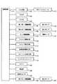
図1、図2を参照して第1実施形態に係るインクジェットプリンタについて説明する。図1は、第1実施形態に係るインクジェットプリンタ100の概略構成を示す図である。図2は、第1実施形態に係るインクジェットプリンタ100の構成を示すブロック図である。<First Embodiment>
The inkjet printer according to the first embodiment will be described with reference to FIGS. 1 and 2. FIG. 1 is a diagram illustrating a schematic configuration of an
第1実施形態に係るインクジェットプリンタ100は、図1に示すように、インクジェットヘッド110と、サブタンク141と、インクジェットヘッド110とサブタンク141を接続する第3チューブ144と、メインタンク131と、第1ポンプ136を含むインク供給手段と、第2ポンプ137を含むインク回収手段と、攪拌装置としての攪拌モータ133及び攪拌子134と、を備える。 As shown in FIG. 1, the
第1チューブ138は一端がサブタンク141に収容され、他端はメインタンク131に収容されている。第2チューブ139は一端がサブタンク141に収容され、他端はメインタンク131に収容されている。第3チューブ144は一端がサブタンク141に接続され、他端はインクジェットヘッド110に接続されている。なお、第1チューブ138、第2チューブ139、第3チューブ144は、インクジェットプリンタの仕様に対応した任意のチューブを使用することができる。 One end of the
インク供給手段は、第1ポンプ136と第1チューブ138で構成される。第1チューブ138は、途中に第1ポンプ136を備える。第1ポンプ136は第1ポンプ駆動回路181によって動作し、その動作は制御回路171が制御する。第1ポンプ136を駆動させると、第1チューブ138内部のインク132はメインタンク131側からサブタンク141側へ移送される。なお、インク供給手段は第1チューブ138の途中に不図示の交換可能なフィルタを備えることが好ましい。 The ink supply means includes a
インク回収手段は、第2ポンプ137と第2チューブ139で構成される。第2チューブ139は、途中に第2ポンプ137を備える。第2ポンプ137は第2ポンプ駆動回路182によって動作し、その動作は制御回路171が制御する。第2ポンプ137を駆動させると、第2チューブ139内部のインクはサブタンク141側からメインタンク131側へ移送される。 The ink collecting means includes a
第1チューブ138と第2チューブ139は、サブタンク141及びメインタンク131を介してインク循環経路を構成する。第1チューブ138及び第3チューブ144は、サブタンク141を介してメインタンク131からインクジェットヘッド110へのインク供給経路を構成する。 The
インクジェットヘッド110は、ノズルから記録媒体124上へインクを吐出して記録媒体124上に画像を形成する。記録媒体124は、搬送ローラ122、123を含む記録媒体搬送手段178によって搬送される。インクジェットヘッド110は、ノズル面がプラテン121に対向するように配置され、インクはプラテン121上に搬送された記録媒体124上に吐出される。 The
ここで、記録媒体124としては、例えば、紙、布、樹脂シートを挙げることができ、その画像形成面は透明、黒色、白色その他の任意のものを用いることができる。 Here, examples of the
インクジェットヘッド110は、キャリッジ走査手段179によって、プラテン121の上方において記録媒体124の搬送方向と直交する方向、すなわち図1の紙面奥行き方向、に沿って移動する。 The
画像データは、入力手段172を介してホストコンピュータ173から入力され、RAM(Random Access Memory)174に記憶され、画像形成時に制御回路171によって読み出される。入力手段172としては、例えば電源スイッチ、キーボード、マウス、外部機器とのインターフェイス回路などを挙げることができる。制御回路171は、画像データにしたがって、記録媒体搬送手段178及びキャリッジ走査手段179を動作させて、記録媒体124の搬送及びインクジェットヘッド110の走査をそれぞれ制御するとともに、インクジェットヘッド110の所定ノズルから所定のタイミングでインクを吐出させて記録媒体124上に画像を形成させる。 The image data is input from the
記録媒体124の搬送制御、インクジェットヘッド110の走査制御、及び、インク吐出パターンの制御は、ROM(Read Only Memory)175に予め記憶されたプログラムにしたがって、制御回路171が行う。 The
インクジェットヘッド110の走査方向の一端にはホームポジションが設けられている。ホームポジションでは、キャップによりノズル面を気密に覆った状態でインクを吐出または吸引させることができ、これにより、ノズル内のインクの状態の調整やノズル面の洗浄を行うことができる。 A home position is provided at one end of the
キャップは、インクジェットヘッド110がホームポジションで静止しているときに、キャップ昇降手段176によって退避位置からインクジェットヘッド110のノズル面を覆う位置に移動する。キャップ昇降手段176の動作は制御回路171が制御する。 The cap is moved from the retracted position to a position covering the nozzle surface of the
また、キャップにはキャップ吸引手段177が接続されており、気密に覆った状態でノズル面及びノズル内のインクを吸引する。キャップ吸引手段177は、例えばポンプであって、制御回路171がその動作を制御する。 Further, a cap suction means 177 is connected to the cap, and sucks ink in the nozzle surface and the nozzle in a state of being airtightly covered. The cap suction means 177 is, for example, a pump, and the
サブタンク141は、インクジェットヘッド110に供給するインク142を内部に収容する。サブタンク141は、収容するインクの種類や外部環境に対応した耐久性を備えていれば任意の材質で構成できる。また、容量やインクジェットプリンタ100の構造によっては、複数の容器で構成してもよい。 The
サブタンク141は、図2に示すように、内部のインク量を複数段階で検出する検出部143を備える。検出部143としては、サブタンク141内のインク142の組成に影響を与えないものであれば任意のものを用いることができ、例えば光学的または電気的または磁気的にインク量を検出するものを用いることができる。検出部143による検出結果は制御回路171へ出力される。 As shown in FIG. 2, the
検出部143は、サブタンク141内のインク量を複数段階、具体的には、容量の100%、75%、50%、25%、または0%の5段階、で検出できると好ましい。しかし、検出部143の検出機能が限られている場合、具体的には1段階検出の場合、検出部143はインク量の上限値検出用として使用することが好ましい。この場合、インク量の下限値検出は、インクジェットヘッド110からのインク吐出量と、第2ポンプ137によるインク回収量とを制御回路171によって計算し、サブタンク141内のインク量上限値からインク吐出量とインク回収量とを減ずることで得られるサブタンク141内のインク量推定値、をもって代用可能である。 It is preferable that the
メインタンク131は、サブタンク141に供給するインク132を内部に収容する。メインタンク131は、収容するインクの種類や外部環境に対応した耐久性を備えていれば任意の材質で構成できる。さらに、容量やインクジェットプリンタ100の構造によっては、複数の容器で構成してもよい。 The
メインタンク131内にはインク132を攪拌するための攪拌子134が配されている。この攪拌子134はメインタンク131の外部に配置された攪拌モータ133によって回転駆動される。攪拌モータ133はモータ駆動回路135によって動作し、その動作は制御回路171によって制御される。攪拌装置は、攪拌モータ133、攪拌子134、及びモータ駆動回路135によって構成される。攪拌装置は本実施形態において必須の構成ではなく、インク特性に応じて、攪拌装置の有無を選択できる。 A
インクの循環について説明する。まず、第2ポンプ137を駆動させることによってサブタンク141内のインク142をメインタンク131に回収する。 The ink circulation will be described. First, the
サブタンク141内のインク142が予め設定された量まで減少したことを検出部143が検出すると、制御回路171は、第1ポンプ136を駆動させてメインタンク131からサブタンク141へインクを供給する。検出部143によるインク量検出の代わりに、前述のサブタンク141内のインク量推定値、を用いてもよい。 When the
サブタンク141へのインク供給においては、第2ポンプ137を駆動させ続けてもよいが、サブタンク141へ供給する量を回収される量よりも多くする観点からは、第2ポンプ137を停止することが好ましい。 In supplying ink to the
サブタンク141内のインク量が所定量に達したことを検出部143が検出すると、制御回路171は、第1ポンプ136を停止して第1チューブ138内のインクの流れを停止させる。 When the
サブタンク141へのインク供給についてより具体的に説明する。サブタンク141のインク量の制御は、制御回路171でおこなう。ROM175内に予めインク容量の下限値と上限値を記憶させ、制御回路171は検出部143によってサブタンク141のインク量を検出し、検出されたインク量と記憶された下限値あるいは上限値を比較する。検出部143によるインク量検出の代わりに、前述のサブタンク141内のインク量推定値、を用いることができる。 The ink supply to the
比較の結果に基づいて第1ポンプ136の動作を制御し、サブタンク141内へのインク供給を制御する。すなわち、制御回路171は、検出部143、または前述のサブタンク141内のインク量推定値、によってサブタンク141内のインク量が記憶された下限値、例えばサブタンク容量の25%、を下回ることを検出すると、第1ポンプ駆動回路181に第1ポンプ136を駆動するように指令をする。第1ポンプ136が駆動されると、インクがメインタンク131からサブタンク141内に供給される。制御回路171は、検出部143によって検出されるサブタンク141内のインク量が記憶された上限値、例えばサブタンク容量の100%、になるまで、第1ポンプ駆動回路181を制御して第1ポンプ136を駆動させる。制御回路171は、検出部143によってサブタンク141内のインク量が記憶された上限値、例えばサブタンク容量の100%、であることを検出すると、第1ポンプ駆動回路181を制御して第1ポンプ136を停止させる。 Based on the comparison result, the operation of the
インクの循環は以上のように行う。ここで、第1ポンプ136と第2ポンプ137のインク送液能力が同一とすると、両者を駆動させた状態でインクの循環を継続することができる。なお、この場合も、インクの循環はまずサブタンク141内のインクを回収することから開始する。 The ink circulation is performed as described above. Here, if the ink pumping capabilities of the
画像形成中は、サブタンク141には常にインクがあることが必要であり、例えばインク量がサブタンク容量の25%から100%の範囲内に収まるように制御する。より好ましくは、サブタンク容量の75%から100%の範囲である。メインタンク131のインク残容量がない場合、メインタンク131に不図示の手段によりインクを追加するまでの間、サブタンク141内のインクだけで画像形成させ続ける必要があるので、サブタンク141のインク量の下限値は大きい値、具体的にはサブタンク容量の75%、に設定するのが好ましい。 During image formation, it is necessary for the
循環動作中は、サブタンク141のインク量の下限値が大きい値、具体的にはサブタンク容量の75%、に設定されていると、サブタンク141内のインク142の一部が入れ替わらずに滞留し、沈殿する可能性があるので好ましくない。したがって、循環動作中のみ、一時的にサブタンク141の下限値を小さい値、具体的にはサブタンク容量の25%、に設定できることが好ましい。 During the circulation operation, if the lower limit value of the ink amount in the
画像形成中以外に循環動作を行う場合は、サブタンク141内のインク量の下限値検出を行わずに、予め設定された時間をかけて第2ポンプ137を駆動し、サブタンク141内のインク142を空にしてから、第1ポンプ136を駆動し、メインタンク131からサブタンク141へインクを供給してもよい。 When the circulation operation is performed other than during image formation, the
このような構成にすることにより、インク循環経路でインクを循環させることができるため、顔料の沈殿を防止してインクの濃度を一定に維持することが可能となる。 With such a configuration, the ink can be circulated through the ink circulation path, so that the precipitation of the pigment can be prevented and the ink concentration can be kept constant.
インクの循環動作は、入力手段172またはタイマ180からの信号に基づいて、制御回路171が制御する。 The
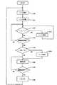
ここで、タイマ180を用いてインクの循環動作を行う場合の処理の流れについて、図3を参照して説明する。図3は、画像形成及びインク処理の流れを示すフローチャートである。 Here, the flow of processing when the ink circulation operation is performed using the
まず、ステップS100において、インク供給の前に攪拌子134を回転させてメインタンク131内のインク132を攪拌し、インク132の濃度を均一にする。 First, in step S100, the
つづいて、ステップS101において、第1ポンプ136を駆動してメインタンク131内のインク132をサブタンク141に供給する。 Subsequently, in step S101, the
サブタンク141にインクを充填した後は、キャップ昇降手段176を上昇させインクジェットヘッド110をキャップし、キャップ吸引手段177を駆動してインクジェットヘッド110からインクを吸引する。これにより、サブタンク141内のインク142を、第3チューブ144を介してインクジェットヘッド110に充填する。 After the
インクジェットヘッド110にインクを充填した後は、タイマ180で経過時間t1、t2を測定する。ここでt1はインク循環を管理する変数、t2はインクジェットヘッドからのインク排出を管理する変数である。ステップS102において、制御回路171は、経過時間t1が予め定めた所定時間T1に達したか否かを判断する。所定時間T1は、インク特性に応じて、インクが沈殿しない時間を設定することが好ましく、例えば24時間に設定する。 After the
経過時間t1が所定時間T1に達した場合、すなわちステップS102でYESの場合、ステップS107においてインクを循環させる。ここで、図4のフローチャートを参照して、ステップS107のインク循環について詳細に説明する。 If the elapsed time t1 reaches the predetermined time T1, that is, if YES in step S102, the ink is circulated in step S107. Here, the ink circulation in step S107 will be described in detail with reference to the flowchart of FIG.
ステップS107のインク循環に移行すると、ステップS200において、攪拌子134を回転させてメインタンク131内のインク132を攪拌し、インク132の濃度を均一にする。 After shifting to the ink circulation in step S107, in step S200, the
次に、ステップS201において、第2ポンプ137を駆動させてサブタンク141内のインク142をメインタンク131へ回収する。サブタンク141内のインク量が予め設定された量、例えばサブタンク容量の25%、まで減少したことを検出部143が検出すると、制御回路171は第2ポンプ137を停止する。前述した通り、検出部143によるインク量検出のかわりに、前述のサブタンク141内のインク量推定値、を用いることができる。 Next, in step S <b> 201, the
次に、ステップS202において、第1ポンプ136を駆動させて、メインタンク131内のインク132をサブタンク141へ供給する。サブタンク141内のインク量が予め設定された量、例えばサブタンク容量の100%、に達したことを検出部143が検出すると、制御回路171は、第1ポンプ136を停止する。 Next, in step S202, the
次に、ステップS203において、制御回路171はインク循環回数nが予め定めた所定回数Nに達したか否かを判断する。所定回数Nは、サブタンク141と第1チューブ138と第2チューブ139のインクがすべて入れ替わる回数に設定することが好ましく、例えば10回に設定する。 In step S203, the
インク循環回数nが所定回数Nに達していない場合、すなわちステップS203でNOの場合、ステップS206においてインク循環回数nに1を加え、ステップS201に戻る。 If the ink circulation number n has not reached the predetermined number N, that is, if NO in step S203, 1 is added to the ink circulation number n in step S206, and the process returns to step S201.
インク循環回数nが所定回数Nに達した場合、すなわちステップS203でYESの場合、ステップS204において、攪拌子134を回転させてメインタンク131内のインク132を攪拌し、インク132の濃度を均一にする。続いて、ステップS205において、インク循環回数nを0に戻し、経過時間t1を0に戻し、ステップS107のインク循環を終了する。ステップS107のインク循環を終了したら、ステップS102において、タイマ180による経過時間t1の測定を再開する。 When the ink circulation number n reaches the predetermined number N, that is, when YES in step S203, in step S204, the
経過時間t1が所定時間T1に達していない場合、すなわちステップS102でNOの場合、ステップS103で画像形成を行うか否かを判断する。この判断は、画像形成開始信号の入力の有無に対応する。 If the elapsed time t1 has not reached the predetermined time T1, that is, if NO in step S102, it is determined in step S103 whether or not to perform image formation. This determination corresponds to whether or not an image formation start signal is input.
画像形成を開始しない場合、すなわちステップS103においてNOの場合、ステップS102において、タイマ180による経過時間t1の測定を継続する。 If image formation is not started, that is, if NO in step S103, measurement of elapsed time t1 by
画像形成を開始する場合、すなわちステップS103においてYESの場合、ステップS104において、制御回路171は、経過時間t2が予め定めた所定時間T2に達したか否かを判断する。所定時間T2は、インク特性に応じて、インクが沈殿しない時間を設定することが好ましく、例えば24時間に設定する。 When image formation is started, that is, when YES in step S103, in step S104, the
経過時間t2が所定時間T2に達した場合、すなわちステップS104においてYESの場合、ステップS108において、インクジェットヘッド110をホームポジションに移動して、キャップ昇降手段176及びキャップ吸引手段177を用いてノズルからインクを吸引して外部へ排出させる。この工程においては、インクジェットヘッド110及び第3チューブ144内のインクを排出することが好ましい。ステップS108におけるインク排出後は、ステップS105において画像形成を開始する。 If the elapsed time t2 reaches the predetermined time T2, that is, if YES in step S104, the
一方、経過時間t2が所定時間T2に達しない場合、すなわちステップS104においてNOの場合、ステップS105において画像形成を開始する。 On the other hand, if the elapsed time t2 does not reach the predetermined time T2, that is, if NO in step S104, image formation is started in step S105.
画像形成が終了した場合、すなわちステップS106においてYESの場合、ステップS109において経過時間t1、t2をそれぞれ0に戻してから、ステップS100のインク攪拌、ステップS101のインク充填を行い、ステップS102において、タイマ180による経過時間t1の測定を再開する。 When the image formation is completed, that is, in the case of YES in step S106, after the elapsed times t1 and t2 are returned to 0 in step S109, ink stirring in step S100 and ink filling in step S101 are performed, and in step S102, a timer is set. The measurement of the elapsed time t1 by 180 is resumed.
このように、タイマ180を用いてインク循環を行っていない時間を測定し、経過時間t1が所定時間T1を経過した場合に、ステップS107のインク循環を行うと、サブタンク141とメインタンク131と第1チューブ138と第2チューブ139で構成されるインク循環経路内に存在するインクの顔料の沈殿を防止してインク濃度を所望の一定値に維持することができる。 As described above, when the time during which ink circulation is not performed is measured using the
さらに、タイマ180を用いてインク排出を行っていない時間を測定し、経過時間t2が所定時間T2を経過した場合は、ステップS105の画像形成を開始する前に、ステップS108において、インクジェットヘッド110及び第3チューブ144内のインクを排出すると、メインタンク131からインクジェットヘッド110までのインク供給経路は、濃度を所望の一定値に維持されたインクで満たされるため、濃度が不均一なインクによる画像形成を防ぐことができる。 Furthermore, when the time during which ink is not discharged is measured using the
このように、所定時間T2以上画像形成を行わずにインクジェットヘッド110及び第3チューブ144からインクを排出させても、インク排出は画像形成開始前の1回のみであり、その排出量が少ないためインクを無駄に消費してしまうことを防ぐことができる。 As described above, even if the ink is discharged from the
<第2実施形態>
つづいて、図5、図6を参照して、本発明の第2実施形態について説明する。図5は、第2実施形態に係るインクジェットプリンタ200の概略構成を示す図である。図6は、第2実施形態に係るインクジェットプリンタ200の構成を示すブロック図である。Second Embodiment
Next, a second embodiment of the present invention will be described with reference to FIGS. FIG. 5 is a diagram illustrating a schematic configuration of an
第2実施形態に係るインクジェットプリンタ200においては、サブタンク141内のインク142に作用するインク圧を所定の値に調整するためのインク圧力調整手段が設けられ、さらにインク圧を検出するインク圧センサ245を備えている点が第1実施形態に係るインクジェットプリンタ100と異なる。その他の構成は第1実施形態と同様であって、同じ部材については同じ参照符号を使用する。 In the
インクジェットプリンタ200では、インク圧力調整手段によりサブタンク141内のインク142に作用するインク圧を所定の値に調整することができるため、サブタンク141は記録媒体の搬送方向に対して交差する方向に往復移動するキャリッジに搭載することが可能である。 In the
インクジェットプリンタ200では、第4チューブ246は、一端がサブタンク141内に収容され、他端は大気開放された廃インクタンク253内に収容されている。第4チューブ246は、空気を移送する経路であるため、端部がサブタンク141内のインク142や廃インクタンク253内の廃インクで塞がれないように配置する。 In the
廃インクタンク253は、他の目的で用意された廃インクタンク、例えばキャップ吸引したインクを回収する廃インクタンク、と共通化することが可能である。なお、第4チューブ246は、インクジェットプリンタの仕様に対応した任意のチューブを使用することができる。 The
インク圧力調整手段は、第3ポンプ252と第4チューブ246で構成される。第4チューブ246は、途中に第3ポンプ252を備える。第3ポンプ252は第3ポンプ駆動回路283によって動作し、その動作は制御回路171が制御する。第3ポンプ252の駆動は正転、逆転の両方が選択でき、本実施形態ではサブタンク141内部の空気が減圧される方向、すなわちサブタンク141内部の空気がサブタンク141から廃インクタンク253へ移送される方向、を第3ポンプ252の正転とする。 The ink pressure adjusting means includes a
なお、インク圧力調整手段は、サブタンク141内部の急激な空気圧変動を緩和するために、サブタンク141と第3ポンプ252を接続する第4チューブ246の途中に、バッファタンク251を備えることが好ましい。 The ink pressure adjusting means preferably includes a
インク圧センサ245は、サブタンク141内のインク142に作用するインク圧を検出できる位置に配置する。 The
インクジェットヘッド110内のインクと、第3チューブ144内のインクと、サブタンク141内のインク142は、連続する一塊の液体であるため、ある1点のインク圧を検出できれば、他点のインク圧は水頭差を考慮することにより求めることができる。具体的には、インク圧センサ245は、図5のように第3チューブ144に接続する位置のほか、インクジェットヘッド110に接続する位置、サブタンク141に接続する位置に配置してもインク142に作用するインク圧を検出することができる。 Since the ink in the
インク圧センサ245の検出結果は制御回路171へ出力される。インク圧センサ245の検出結果が所定の目標値と一致しないとき、制御回路171は、第3ポンプ252を正転または逆転させてサブタンク141内の空気圧を変動させ、インク圧センサ245の検出結果が所定の目標値と一致するように制御する。 The detection result of the
第2実施形態におけるインク圧力調整手段の動作について、より具体的に説明する。 The operation of the ink pressure adjusting means in the second embodiment will be described more specifically.
安定的に画像形成を行うためには、インクジェットヘッド110において、インクがノズル面でメニスカスを形成し、ノズルを満たした状態を保つようにする必要がある。ノズル面におけるインク圧Pnは弱負圧、具体的には−3[kPa]以上0[kPa]以下、であることが好ましい。 In order to stably form an image, in the
インクジェット110のノズル面と、インク圧センサ245の検出位置との鉛直方向距離をhとする。インク圧センサ245の検出値Psとノズル面におけるインク圧Pnの関係は、インク密度ρ、重力加速度gを用いて
Ps=Pn−ρgh・・・(1)
と表される。例えば、ノズル面におけるインク圧Pnの目標値が−1.0[kPa]、h=0.1[m]、インク密度ρ=1.0[kg/m^3]、重力加速度g=9.8[m/s^2]のとき、検出値Psの目標値は−1.98[kPa]である。The vertical distance between the nozzle surface of the
It is expressed. For example, the target value of the ink pressure Pn on the nozzle surface is −1.0 [kPa], h = 0.1 [m], the ink density ρ = 1.0 [kg / m ^ 3], and the gravitational acceleration g = 9. When 8 [m / s ^ 2], the target value of the detection value Ps is −1.98 [kPa].
インク圧センサ245の検出値Psが正圧側に変動したとき、例えば検出値Psが−1.80[kPa]のとき、制御回路171は、第3ポンプ252を正転させてサブタンク141内の空気を減圧し、検出値Psが目標値と一致するように制御する。 When the detected value Ps of the
逆に、検出値Psが負圧側に変動したとき、例えば検出値Psが−2.2[kPa]のとき、制御回路171は、第3ポンプ252を逆転させてサブタンク141内の空気を加圧し、検出値Psが目標値と一致するように制御する。 Conversely, when the detected value Ps fluctuates to the negative pressure side, for example, when the detected value Ps is -2.2 [kPa], the
インクの循環の動作と手順は第1実施形態と同様である。 The operation and procedure of ink circulation are the same as in the first embodiment.
第2実施形態に係るインクジェットプリンタ200では、インク供給とインク回収の際に生じるインク圧の変動を、上記インク圧力調整手段により緩和し、インクジェットヘッド110のノズル面におけるインク圧Pnを適切な弱負圧に維持することが可能である。 In the
したがって、第2実施形態に係るインクジェットプリンタ200では、画像形成中であってもインク供給やインク回収、インク循環を行うことができる。 Therefore, the
<第3実施形態>
つづいて、図7、図8を参照して、本発明の第3実施形態について説明する。図7は、第3実施形態に係るインクジェットプリンタ300の概略構成を示す図である。図8は、第3実施形態に係るインクジェットプリンタ300の構成を示すブロック図である。<Third Embodiment>
Next, a third embodiment of the present invention will be described with reference to FIGS. FIG. 7 is a diagram illustrating a schematic configuration of an
第3実施形態に係るインクジェットプリンタ300においては、第2実施形態のサブタンク141と第3ポンプ252を接続する第4チューブ246の途中に、空気圧センサ354が設けられている点が第2実施形態と異なる。第3実施形態においては、インク圧センサ245は必須の構成要素ではないため不図示とした。 The
第3実施形態において、バッファタンク251を備える場合、バッファタンク251は空気圧センサ354と第3ポンプ252を接続する第4チューブ246の途中に配置することが好ましい。 In the third embodiment, when the
その他の構成は第2実施形態と同様であって、同じ部材については同じ参照符号を使用する。 Other configurations are the same as those of the second embodiment, and the same reference numerals are used for the same members.
空気圧センサ354の検出結果は制御回路171へ出力される。空気圧センサ354の検出結果が所定の目標値と一致しないとき、制御回路171は、第3ポンプ252を正転または逆転させてサブタンク141内の空気圧を変動させ、空気圧センサ354の検出結果が所定の目標値と一致するように制御する。 The detection result of the
第3実施形態におけるインク圧力調整手段の動作について、より具体的に説明する。 The operation of the ink pressure adjusting means in the third embodiment will be described more specifically.
安定的に画像形成を行うためには、インクジェットヘッド110において、インクがノズル面でメニスカスを形成し、ノズルを満たした状態を保つようにする必要がある。ノズル面におけるインク圧Pnは弱負圧、具体的には−3[kPa]以上0[kPa]以下、であることが好ましい。 In order to stably form an image, in the
インクジェットヘッド110のノズル面と、サブタンク141内のインク142の液面との鉛直方向距離をHとする。空気圧センサ354の検出値Paとノズル面におけるインク圧Pnの関係は
Pa=Pn−ρgH・・・(2)
と表される。The vertical distance between the nozzle surface of the
It is expressed.
(2)式において、Hの変化が少ない場合、言い換えると、Hが一定とみなせる場合、について具体的に説明する。ノズル面におけるインク圧Pnの目標値が−1.0[kPa]、H=0.2[m]、インク密度ρ=1.0[kg/m^3]、重力加速度g=9.8[m/s^2]のとき、検出値Paの目標値Ptは−2.96[kPa]である。 In the formula (2), the case where the change of H is small, in other words, the case where H can be regarded as constant will be specifically described. The target value of the ink pressure Pn on the nozzle surface is −1.0 [kPa], H = 0.2 [m], the ink density ρ = 1.0 [kg / m ^ 3], and the gravitational acceleration g = 9.8 [ When m / s ^ 2], the target value Pt of the detected value Pa is -2.96 [kPa].
空気圧センサ354の検出値Paが正圧側に変動したとき、例えば検出値Paが−2.80[kPa]のとき、制御回路171は、第3ポンプ252を正転させてサブタンク141内の空気を減圧し、検出値Paが目標値Ptと一致するように制御する。 When the detection value Pa of the
逆に、検出値Paが負圧側に変動したとき、例えば検出値Paが−3.2[kPa]のとき、制御回路171は、第3ポンプ252を逆転させてサブタンク141内の空気を加圧し、検出値Paが目標値Ptと一致するように制御する。 Conversely, when the detected value Pa changes to the negative pressure side, for example, when the detected value Pa is −3.2 [kPa], the
(2)式において、Hが変数の場合については第4実施形態にて説明する。 In the formula (2), the case where H is a variable will be described in the fourth embodiment.
インクの循環の動作と手順は第1実施形態と同様である。 The operation and procedure of ink circulation are the same as in the first embodiment.
第3実施形態に係るインクジェットプリンタ300では、インク供給とインク回収の際に生じるインク圧の変動を、上記インク圧力調整手段により緩和し、インクジェットヘッド110のノズル面におけるインク圧Pnを適切な弱負圧に維持することが可能である。 In the
したがって、第3実施形態に係るインクジェットプリンタ300では、画像形成中であってもインク供給やインク回収、インク循環を行うことができる。 Therefore, the
<第4実施形態>
つづいて、本発明の第4実施形態について説明する。第4実施形態の構成は第3実施形態と同様であって、同じ部材については同じ参照符号を使用する。<Fourth embodiment>
Subsequently, a fourth embodiment of the present invention will be described. The configuration of the fourth embodiment is the same as that of the third embodiment, and the same reference numerals are used for the same members.
第4実施形態においては、インクジェットヘッド110のノズル面と、サブタンク141内のインク142の液面との鉛直方向距離を変数として扱うため、空気圧センサ354の目標値も変数になる点が第3実施形態と異なる。 In the fourth embodiment, since the vertical distance between the nozzle surface of the
制御回路171は、所定のタイミングで、サブタンク141内のインク142の液面位置を把握し、インクジェットヘッド110のノズル面と、インク142の液面との鉛直方向距離を算出する。算出した鉛直方向距離を(2)式に適用し、空気圧センサ354の目標値を求める。空気圧センサ354の検出結果が目標値と一致しないとき、制御回路171は、第3ポンプ252を正転または逆転させてサブタンク141内の空気圧を変動させ、空気圧センサ354の検出結果が所定の目標値と一致するように制御する。 The
第4実施形態におけるインク圧力調整手段の動作について、より具体的に説明する。 The operation of the ink pressure adjusting means in the fourth embodiment will be described more specifically.
安定的に画像形成を行うためには、インクジェットヘッド110において、インクがノズル面でメニスカスを形成し、ノズルを満たした状態を保つようにする必要がある。ノズル面におけるインク圧Pnは弱負圧、具体的には−3[kPa]以上0[kPa]以下、であることが好ましい。 In order to stably form an image, in the
サブタンク141内のインク142の液面位置は、第1実施形態で説明したサブタンク141内のインク量推定値、または検出部143によって把握できる。ただし、検出部143の検出点が限られている場合、例えば5点検出の場合、はインク142の液面位置を正確に把握することができないので、前述のインク量推定値を用いることが好ましい。 The liquid level position of the
インクジェットヘッド110のノズル面と、インク142の液面位置との鉛直方向距離がH[m]、ノズル面におけるインク圧Pnの目標値が−1.0[kPa]、インク密度ρ=1.0[kg/m^3]、重力加速度g=9.8[m/s^2]のとき、空気圧センサ354の目標値Ptは(2)式より
Pt=−1.0−9.8H・・・(3)
と表される。The vertical distance between the nozzle surface of the
It is expressed.
まず、制御回路171は、所定のタイミングで、サブタンク141内のインク142の液面位置を把握する。次に、インク142の液面位置をもとに鉛直方向距離Hを算出し、(3)式により空気圧センサ354の目標値Ptを定める。 First, the
空気圧センサ354の検出結果Paが目標値Ptと一致しないとき、制御回路171は、第3ポンプ252を正転または逆転させてサブタンク141内の空気圧を変動させ、空気圧センサ354の検出結果Paが目標値Ptと一致するように制御する。 When the detection result Pa of the
インクの循環の動作と手順は第1実施形態と同様である。 The operation and procedure of ink circulation are the same as in the first embodiment.
第4実施形態に係るインクジェットプリンタでは、インク供給とインク回収の際に生じるインク圧の変動を、上記インク圧力調整手段により緩和し、インクジェットヘッド110のノズル面におけるインク圧Pnを適切な弱負圧に維持することが可能である。 In the ink jet printer according to the fourth embodiment, fluctuations in ink pressure that occur during ink supply and ink recovery are alleviated by the ink pressure adjusting means, and the ink pressure Pn on the nozzle surface of the
さらに、第4実施形態に係るインクジェットプリンタは、サブタンク141内のインク量の変化による水頭値変動を補正することができるため、第3実施形態と比較してインクジェットヘッド110のノズル面におけるインク圧Pnをより適切な弱負圧に維持することが可能である。 Furthermore, since the ink jet printer according to the fourth embodiment can correct the head value fluctuation due to the change in the ink amount in the
したがって、第4実施形態に係るインクジェットプリンタでは、画像形成中であってもインク供給やインク回収、インク循環を行うことができる。 Therefore, the ink jet printer according to the fourth embodiment can perform ink supply, ink recovery, and ink circulation even during image formation.
本発明について上記実施形態を参照しつつ説明したが、本発明は上記実施形態に限定されるものではなく、改良の目的または本発明の思想の範囲内において改良または変更が可能である。 Although the present invention has been described with reference to the above embodiment, the present invention is not limited to the above embodiment, and can be improved or changed within the scope of the purpose of the improvement or the idea of the present invention.
以上のように、本発明に係るインクジェットプリンタは、長時間の放置によりインク濃度が変化しやすいインクを用いる場合に有用である。 As described above, the ink jet printer according to the present invention is useful when using an ink whose ink density is likely to change when left for a long time.
100 インクジェットプリンタ
110 インクジェットヘッド
121 プラテン
122 搬送ローラ
123 搬送ローラ
124 記録媒体
131 メインタンク
132 インク
133 攪拌モータ
134 攪拌子
135 モータ駆動回路
136 第1ポンプ
137 第2ポンプ
138 第1チューブ
139 第2チューブ
141 サブタンク
142 インク
143 検出部
144 第3チューブ
171 制御回路
172 入力手段
173 ホストコンピュータ
174 RAM
175 ROM
176 キャップ昇降手段
177 キャップ吸引手段
178 記録媒体搬送手段
179 キャリッジ走査手段
180 タイマ
181 第1ポンプ駆動回路
182 第2ポンプ駆動回路
200 インクジェットプリンタ
245 インク圧センサ
246 第4チューブ
251 バッファタンク
252 第3ポンプ
253 廃インクタンク
283 第3ポンプ駆動回路
300 インクジェットプリンタ
354 空気圧センサDESCRIPTION OF
175 ROM
176 Cap raising / lowering means 177 Cap suction means 178 Recording medium conveying means 179 Carriage scanning means 180
Claims (9)
Translated fromJapanesePriority Applications (2)
| Application Number | Priority Date | Filing Date | Title |
|---|---|---|---|
| JP2009283332AJP5297363B2 (en) | 2009-12-14 | 2009-12-14 | Inkjet printer |
| PCT/JP2010/068681WO2011074324A1 (en) | 2009-12-14 | 2010-10-22 | Ink-jet printer |
Applications Claiming Priority (1)
| Application Number | Priority Date | Filing Date | Title |
|---|---|---|---|
| JP2009283332AJP5297363B2 (en) | 2009-12-14 | 2009-12-14 | Inkjet printer |
Publications (2)
| Publication Number | Publication Date |
|---|---|
| JP2011121344Atrue JP2011121344A (en) | 2011-06-23 |
| JP5297363B2 JP5297363B2 (en) | 2013-09-25 |
Family
ID=44167090
Family Applications (1)
| Application Number | Title | Priority Date | Filing Date |
|---|---|---|---|
| JP2009283332AExpired - Fee RelatedJP5297363B2 (en) | 2009-12-14 | 2009-12-14 | Inkjet printer |
Country Status (2)
| Country | Link |
|---|---|
| JP (1) | JP5297363B2 (en) |
| WO (1) | WO2011074324A1 (en) |
Cited By (9)
| Publication number | Priority date | Publication date | Assignee | Title |
|---|---|---|---|---|
| JP2014076577A (en)* | 2012-10-10 | 2014-05-01 | Seiko Epson Corp | Printer and maintenance method therefor |
| JP2015024653A (en)* | 2013-06-19 | 2015-02-05 | セイコーエプソン株式会社 | inkjet printer |
| CN105415886A (en)* | 2014-09-11 | 2016-03-23 | 精工爱普生株式会社 | Flow Path Member, Liquid Ejecting Head, Liquid Ejecting Apparatus And Liquid Stirring Method |
| JP2017075302A (en)* | 2015-10-07 | 2017-04-20 | 花王株式会社 | Inkjet recording method |
| CN110154540A (en)* | 2016-01-08 | 2019-08-23 | 佳能株式会社 | Printing device and printing method |
| US10464337B2 (en) | 2018-01-19 | 2019-11-05 | Ricoh Company, Ltd. | Liquid discharge unit and image forming apparatus |
| US10550278B2 (en) | 2015-08-18 | 2020-02-04 | Kao Corporation | Water-based ink for ink-jet recording |
| US10807372B2 (en) | 2018-01-29 | 2020-10-20 | Ricoh Company, Ltd. | Liquid droplet discharging unit, liquid droplet forming device, and stirring device |
| WO2021065463A1 (en)* | 2019-09-30 | 2021-04-08 | ブラザー工業株式会社 | Printing device and computer program |
Citations (5)
| Publication number | Priority date | Publication date | Assignee | Title |
|---|---|---|---|---|
| WO1999034982A1 (en)* | 1998-01-09 | 1999-07-15 | Hitachi, Ltd. | Ink jet recorder |
| JPH11254698A (en)* | 1998-03-09 | 1999-09-21 | Hitachi Ltd | Ink jet recording device |
| JP2005138488A (en)* | 2003-11-07 | 2005-06-02 | Konica Minolta Medical & Graphic Inc | Image recorder |
| JP2006168341A (en)* | 2004-11-16 | 2006-06-29 | Canon Finetech Inc | Ink supply device |
| JP2007137026A (en)* | 2005-11-22 | 2007-06-07 | Fujifilm Corp | Liquid ejection device and liquid stirring method |
- 2009
- 2009-12-14JPJP2009283332Apatent/JP5297363B2/ennot_activeExpired - Fee Related
- 2010
- 2010-10-22WOPCT/JP2010/068681patent/WO2011074324A1/enactiveApplication Filing
Patent Citations (5)
| Publication number | Priority date | Publication date | Assignee | Title |
|---|---|---|---|---|
| WO1999034982A1 (en)* | 1998-01-09 | 1999-07-15 | Hitachi, Ltd. | Ink jet recorder |
| JPH11254698A (en)* | 1998-03-09 | 1999-09-21 | Hitachi Ltd | Ink jet recording device |
| JP2005138488A (en)* | 2003-11-07 | 2005-06-02 | Konica Minolta Medical & Graphic Inc | Image recorder |
| JP2006168341A (en)* | 2004-11-16 | 2006-06-29 | Canon Finetech Inc | Ink supply device |
| JP2007137026A (en)* | 2005-11-22 | 2007-06-07 | Fujifilm Corp | Liquid ejection device and liquid stirring method |
Cited By (15)
| Publication number | Priority date | Publication date | Assignee | Title |
|---|---|---|---|---|
| JP2014076577A (en)* | 2012-10-10 | 2014-05-01 | Seiko Epson Corp | Printer and maintenance method therefor |
| JP2015024653A (en)* | 2013-06-19 | 2015-02-05 | セイコーエプソン株式会社 | inkjet printer |
| CN105415886A (en)* | 2014-09-11 | 2016-03-23 | 精工爱普生株式会社 | Flow Path Member, Liquid Ejecting Head, Liquid Ejecting Apparatus And Liquid Stirring Method |
| US10550278B2 (en) | 2015-08-18 | 2020-02-04 | Kao Corporation | Water-based ink for ink-jet recording |
| JP2017075302A (en)* | 2015-10-07 | 2017-04-20 | 花王株式会社 | Inkjet recording method |
| US10717292B2 (en) | 2015-10-07 | 2020-07-21 | Kao Corporation | Inkjet recording method |
| CN110154540A (en)* | 2016-01-08 | 2019-08-23 | 佳能株式会社 | Printing device and printing method |
| CN110154540B (en)* | 2016-01-08 | 2021-12-24 | 佳能株式会社 | Printing apparatus and printing method |
| US10464337B2 (en) | 2018-01-19 | 2019-11-05 | Ricoh Company, Ltd. | Liquid discharge unit and image forming apparatus |
| US10807372B2 (en) | 2018-01-29 | 2020-10-20 | Ricoh Company, Ltd. | Liquid droplet discharging unit, liquid droplet forming device, and stirring device |
| WO2021065463A1 (en)* | 2019-09-30 | 2021-04-08 | ブラザー工業株式会社 | Printing device and computer program |
| JP2021053975A (en)* | 2019-09-30 | 2021-04-08 | ブラザー工業株式会社 | Printer and computer program |
| US20220212477A1 (en)* | 2019-09-30 | 2022-07-07 | Brother Kogyo Kabushiki Kaisha | Printing apparatus and non-transitory computer-readable storage medium |
| JP7327062B2 (en) | 2019-09-30 | 2023-08-16 | ブラザー工業株式会社 | printing device and computer program |
| US12077002B2 (en)* | 2019-09-30 | 2024-09-03 | Brother Kogyo Kabushiki Kaisha | Printing apparatus and non-transitory computer-readable storage medium |
Also Published As
| Publication number | Publication date |
|---|---|
| WO2011074324A1 (en) | 2011-06-23 |
| JP5297363B2 (en) | 2013-09-25 |
Similar Documents
| Publication | Publication Date | Title |
|---|---|---|
| JP5297363B2 (en) | Inkjet printer | |
| JP5249070B2 (en) | Inkjet printer | |
| JP6543994B2 (en) | Printing device | |
| JP6102167B2 (en) | Printing device | |
| JP7676616B2 (en) | Recording device, control method, and program | |
| JP5879862B2 (en) | Printing apparatus and printing method | |
| US7618115B2 (en) | Image forming apparatus | |
| JP5995187B2 (en) | Image forming apparatus | |
| EP3785919B1 (en) | Printing apparatus and printing system | |
| JP2006088488A (en) | Inkjet recorder and inkjet recording method | |
| JP2015044379A (en) | Liquid discharge device and control method of the same | |
| US9283790B2 (en) | Liquid ejecting method and liquid ejecting apparatus | |
| JP3933660B2 (en) | Image forming apparatus | |
| JP5828389B2 (en) | Liquid filling method and liquid discharge apparatus | |
| JP6569577B2 (en) | Ink jet recording apparatus and refresh method for ink jet recording apparatus | |
| US10434806B2 (en) | Inkjet printer | |
| JP2014079973A (en) | Ink jet recorder | |
| JP6930342B2 (en) | Liquid discharge device | |
| JP5249069B2 (en) | Inkjet printer | |
| JP2016175377A (en) | Liquid consuming device | |
| JP2007268964A (en) | Inkjet recording method and apparatus | |
| JP2008179108A (en) | Recorder | |
| JP5899732B2 (en) | Liquid ejection device | |
| JP2015044378A (en) | Recording device and control method of the same | |
| JP2021169179A (en) | Image formation device |
Legal Events
| Date | Code | Title | Description |
|---|---|---|---|
| A621 | Written request for application examination | Free format text:JAPANESE INTERMEDIATE CODE: A621 Effective date:20121011 | |
| A131 | Notification of reasons for refusal | Free format text:JAPANESE INTERMEDIATE CODE: A131 Effective date:20130129 | |
| A521 | Written amendment | Free format text:JAPANESE INTERMEDIATE CODE: A523 Effective date:20130304 | |
| TRDD | Decision of grant or rejection written | ||
| A01 | Written decision to grant a patent or to grant a registration (utility model) | Free format text:JAPANESE INTERMEDIATE CODE: A01 Effective date:20130611 | |
| A61 | First payment of annual fees (during grant procedure) | Free format text:JAPANESE INTERMEDIATE CODE: A61 Effective date:20130614 | |
| R150 | Certificate of patent or registration of utility model | Ref document number:5297363 Country of ref document:JP Free format text:JAPANESE INTERMEDIATE CODE: R150 Free format text:JAPANESE INTERMEDIATE CODE: R150 | |
| RD04 | Notification of resignation of power of attorney | Free format text:JAPANESE INTERMEDIATE CODE: R3D04 | |
| R250 | Receipt of annual fees | Free format text:JAPANESE INTERMEDIATE CODE: R250 | |
| R250 | Receipt of annual fees | Free format text:JAPANESE INTERMEDIATE CODE: R250 | |
| R250 | Receipt of annual fees | Free format text:JAPANESE INTERMEDIATE CODE: R250 | |
| S111 | Request for change of ownership or part of ownership | Free format text:JAPANESE INTERMEDIATE CODE: R313111 | |
| R350 | Written notification of registration of transfer | Free format text:JAPANESE INTERMEDIATE CODE: R350 | |
| LAPS | Cancellation because of no payment of annual fees |