JP2011120008A - Address conversion apparatus - Google Patents
Address conversion apparatusDownload PDFInfo
- Publication number
- JP2011120008A JP2011120008AJP2009275689AJP2009275689AJP2011120008AJP 2011120008 AJP2011120008 AJP 2011120008AJP 2009275689 AJP2009275689 AJP 2009275689AJP 2009275689 AJP2009275689 AJP 2009275689AJP 2011120008 AJP2011120008 AJP 2011120008A
- Authority
- JP
- Japan
- Prior art keywords
- address
- port number
- source
- gateway
- call
- Prior art date
- Legal status (The legal status is an assumption and is not a legal conclusion. Google has not performed a legal analysis and makes no representation as to the accuracy of the status listed.)
- Pending
Links
- 238000006243chemical reactionMethods0.000titleclaimsabstractdescription31
- 230000005540biological transmissionEffects0.000claimsabstractdescription43
- 238000013519translationMethods0.000claimsdescription71
- 238000012544monitoring processMethods0.000claimsdescription16
- 238000013075data extractionMethods0.000claimsdescription4
- 238000004891communicationMethods0.000abstractdescription13
- 238000012545processingMethods0.000abstractdescription12
- 238000000605extractionMethods0.000description19
- 238000000034methodMethods0.000description7
- 239000000284extractSubstances0.000description6
- 238000000926separation methodMethods0.000description4
- 238000010586diagramMethods0.000description3
- 230000003111delayed effectEffects0.000description1
- 238000001514detection methodMethods0.000description1
Images


Landscapes
- Small-Scale Networks (AREA)
Abstract
Description
Translated fromJapanese本発明は、アドレス変換装置に係り、特にIP回線を使用した音声通話を行なうネットワーク上にあるゲートウェイに付随するアドレス変換装置に関する。 The present invention relates to an address translation device, and more particularly to an address translation device associated with a gateway on a network for performing a voice call using an IP line.
IP電話機のようにIPパケットを使用した音声通話において、ゲートウェイを介して他のネットワークと通話を行う場合、ゲートウェイで音声パケットに関してもアドレス変換を行ない送受信する。この際に、1つのゲートウェイに対して複数の機器が通話を行なうと送受信される音声パケットの量が多くなる。この結果、ゲートウェイでのアドレス変換処理の負荷が非常に大きく、音声パケットの遅延、場合によっては欠落が発生することが考えられる。 In a voice call using an IP packet like an IP telephone, when a call is made with another network via a gateway, the gateway also performs address conversion on the voice packet and transmits / receives it. At this time, when a plurality of devices make a call to one gateway, the amount of voice packets transmitted and received increases. As a result, the load of address translation processing at the gateway is very large, and it is conceivable that voice packets are delayed and possibly lost.
このような特定のパケット送受信の負荷分散に対して、特許文献1では特定のパケットをゲートウェイが受け取った場合、配下にある装置へと前記特定のパケットを転送している。 In contrast to such specific packet transmission / reception load distribution, in Patent Document 1, when a gateway receives a specific packet, the specific packet is transferred to a device under its control.
しかし、特許文献1の技術において、音声通話などの特定のパケットは、ゲートウェイに到達し、且つゲートウェイ内で一旦パケットの種別判定までを行なっている。そのため特定のパケットの受信頻度が高い場合、ゲートウェイ内での処理負荷が大きくパケットの遅延、場合によっては欠落の発生の可能性がある。 However, in the technique of Patent Document 1, a specific packet such as a voice call reaches the gateway, and once the type of the packet is determined in the gateway. For this reason, when the reception frequency of a specific packet is high, the processing load in the gateway is large, and there is a possibility of packet delay and possibly loss.
上述した課題は、外部ネットワークと通信するためにアドレス変換をおこなうゲートウェイ装置と内部ネットワークとに接続し、前記ゲートウェイ装置と前記内部ネットワークとの間でパケットデータを中継し、内部ネットワークから前記ゲートウェイ装置へ中継するパケットデータのうち、呼制御に係るメッセージを監視するメッセージ監視手段と、メッセージ監視手段が発呼または着呼に係るメッセージを検出すると、当該メッセージの送信元アドレスおよび送信元ポート番号並びに該メッセージに含まれる送信先アドレスおよび送信先ポート番号を呼IDと対応付けて記憶するアドレス記憶手段と、内部ネットワークから前記ゲートウェイへ中継する前記パケットデータのうち、リアルタイムパケットデータを抽出するリアルタイムパケットデータ抽出手段と、リアルタイムパケットデータ抽出手段が抽出したリアルタイムパケットデータの送信元アドレスおよび送信元ポート番号を取得し、取得した送信元アドレスおよび送信元ポート番号を検索キーとしてアドレス記憶手段を検索するアドレス検索手段と、一致する送信元アドレスおよび送信元ポート番号を検出したならば、前記抽出したリアルタイムパケットデータの送信先アドレスおよび送信先ポート番号を、アドレス検索手段が検出した送信元アドレスおよび送信元ポート番号に対応する送信先アドレスおよび送信先ポート番号に変換し、ゲートウェイ装置へ中継せずに前記内部ネットワークに送信するアドレス変換送信手段と、を有するアドレス変換装置により、達成できる。 The above-described problem is that the gateway device that performs address conversion to communicate with an external network and the internal network are connected, the packet data is relayed between the gateway device and the internal network, and the internal network to the gateway device. Among the packet data to be relayed, a message monitoring unit that monitors a message related to call control, and when the message monitoring unit detects a message related to an outgoing call or an incoming call, the source address and source port number of the message and the message An address storage means for storing a destination address and a destination port number included in the network in association with a call ID, and a real-time packet for extracting real-time packet data from the packet data relayed from an internal network to the gateway. Address to retrieve the address storage means using the obtained source address and source port number as a search key, and obtain the source address and source port number of the real-time packet data extracted by the packet data extraction means and the real-time packet data extraction means If the transmission means address and the transmission source port number that coincide with the search means are detected, the transmission destination address and transmission destination port number of the extracted real-time packet data are indicated by the transmission source address and the transmission source port detected by the address search means. This can be achieved by an address translation device having address translation and transmission means for translating to a destination address and a destination port number corresponding to the number and transmitting to the internal network without relaying to the gateway device.
本発明に依れば、アドレス変換装置は、ゲートウェイとLANの間に設置し所定のRTPパケットをLANから受信するとゲートウェイには中継せずにアドレス変換処理してLANに送信するので、ゲートウェイの処理軽減となり、パケット遅延または欠落が無く通信をすることが可能となる。 According to the present invention, when the address translation device is installed between the gateway and the LAN and receives a predetermined RTP packet from the LAN, the address translation processing is performed without being relayed to the gateway and is transmitted to the LAN. Thus, communication can be performed without packet delay or loss.
以下、本発明の実施の形態について、実施例を用い図面を参照しながら詳細に説明する。なお、実質同一部位には同じ参照番号を振り、説明は繰り返さない。 Hereinafter, embodiments of the present invention will be described in detail with reference to the drawings using examples. The same reference numerals are assigned to substantially the same parts, and the description will not be repeated.
まず、図1を参照して、通信システムの構成を説明する。図1において、通信システム1000は、外線ネットワーク500に接続されたルータ400、相手電話装置800、相手情報端末700−2と、ルータ400に接続されたLAN100と、LAN100に接続されたSIPサーバ900、アドレス変換装置200、電話装置600、情報端末700−1と、アドレス変換装置200に接続されたゲートウェイ300とから構成されている。 First, the configuration of the communication system will be described with reference to FIG. In FIG. 1, a
ゲートウェイ300は、SIPサーバ900に従属するメディアゲートウェイであって、電話装置600からIPパケットを受信すると、受信したIPパケットを外線ネットワーク500上の相手に送信するために対応するアドレスを変換して、ルータ400に送信する。またアドレス変換したIPパケットをゲートウェイ300から受け取ったルータ400は、外線ネットワーク500上の相手に送信する。外線ネットワーク500からルータ400を介してIPパケット受信した場合も同様である。 When the
SIPサーバ900は、電話装置600と相手電話装置800の間の呼を制御する。アドレス変換装置200は、ゲートウェイ300とLAN100を接続する。電話装置600は、ゲートウェイ300およびルータ400を介して外線ネットワーク500に接続され、相手電話装置800と通信を行なう。情報端末700−1は、ルータ400を介して外線ネットワーク500に接続され、相手情報端末700−2と通信を行なう。図1中の点線は、情報端末700−1、700−2のIPパケットの処理経路を示している。 The SIP server 900 controls calls between the
この通信において、情報端末700−1と相手情報端末700−2の通信に関して、アドレス変換装置200は、何も介入しない。電話装置600と相手電話装置800が通話する場合、アドレス変換装置200は、通話開始時および終了時のSIPメッセージを検出する。アドレス変換装置200は、検出したSIPメッセージから通話に利用するアドレス情報を取得する。アドレス変換装置200は、通話時にはRTPパケットについて、ゲートウェイ300に代わってアドレス変換を行なう。この結果、ゲートウェイ300にはRTPパケットが流れない。 In this communication, the
具体的には、RTPパケットにおけるアドレス変換を説明する。電話装置600から相手電話装置800への送信では、RTPパケットのIPヘッダにある送信元IPアドレスに電話装置600のIPアドレスを送信先IPアドレスにゲートウェイ300のIPアドレスを割り振る。またUDPまたはTCPヘッダにある送信元ポート番号に電話装置の呼で使用する待ち受けポート番号を送信先ポート番号にゲートウェイ300のポート番号を割り振る。 Specifically, address translation in the RTP packet will be described. In transmission from the
アドレス変換装置200は、前記RTPパケットの送信先IPアドレスおよびポート番号がゲートウェイ300宛であることと送信元IPアドレスおよびポート番号が一致するテーブルを検索し、RTPパケットの送信先IPアドレスおよびポート番号をテーブルにあるデータに変換する。ここでは相手電話装置800のIPアドレスおよびポート番号となる。 The
なお、ゲートウェイ300が情報端末700−1と相手情報端末700−2の通信のアドレス変換を行い、アドレス変換装置200がSIPプロトコル以外の音声通信、映像配信等の通信プロトコルも解析できる場合、通話同様に、アドレス変換装置200がゲートウェイ300に代わってアドレス変換を行ってもよい。 If the
また、図1中の実線は、電話装置600と相手電話装置800のRTPパケットの処理経路を示している。一方、一点鎖線は、電話装置600と相手電話装置800のRTPパケットの処理経路を示している。 Further, the solid line in FIG. 1 indicates the processing path of the RTP packet between the
図2を参照して、アドレス変換装置の機能ブロックを説明する。図2において、アドレス変換装置200は、LAN側接続インターフェース部201、LAN→ゲートウェイの中継部202、SIPメッセージ監視部203、変換アドレス抽出部204、変換アドレス記憶部205、RTPパケット抽出部206、ペイロード分離部207、変換RTPパケット送信部208、RTPパケット変換部209、ゲートウェイ→LANの中継部210、ゲートウェイ側接続インターフェース部211から構成される。 With reference to FIG. 2, the functional blocks of the address translation apparatus will be described. 2, the
接続インターフェース部201は、LAN100との接続部である。接続インターフェース部201は、LAN100から受信したパケットデータを全て中継部202へ送信する。また、接続インターフェース部201は、変換RTPパケット送信部208および中継部210から送られてきたパケットデータをLAN100へと送信する。 The
中継部202は、接続インターフェース部201を介してLAN100からパケットデータを受信すると、ゲートウェイ側接続インターフェース部211に送信する。また、中継部202は、RTPパケット抽出部206がRTPパケットを抽出すると、抽出されたRTPパケットを接続インターフェース部211側に送信しない。 When receiving the packet data from the
SIPメッセージ監視部203は、接続インターフェース部201から受け取ったパケットデータのSIPプロトコルを監視する。SIPメッセージ監視部203は、アドレス変換装置に接続されたゲートウェイ300宛のSIPメッセージのうちINVITE、200 OKまたはBYEであれば、当該SIPメッセージを複製する。SIPメッセージ監視部203は、複製したSIPメッセージを、変換アドレス抽出部204へ送信する。また、SIPメッセージ監視部203は、SIPメッセージを含む全てのパケットデータをRTPパケット抽出部206へと送信する。 The SIP
RTPパケット抽出部206は、RTPパケットの送信元IPアドレスおよび送信元ポート番号がSIPメッセージ監視部203からパケットデータを受け取ったとき、変換アドレス記憶部205に記憶されているネットワークアドレスおよびポート番号と一致するか判定する。RTPパケット抽出部206は、一致するRTPパケットのとき、ペイロード分離部207へ送信する。 The RTP
変換アドレス抽出部204は、SIPメッセージ監視部203から受け取ったSIPメッセージの内容を解析する。INVITEまたは200 OKであれば、変換アドレス抽出部204は、通話時に使用するRTPパケットを判別するためのアドレス変換前とアドレス変換後のネットワークアドレスおよびポート番号情報を抜き出す。変換アドレス抽出部204は、変換アドレス記憶部205へ新規にID番号を割り振って保存する。 The translated
図3と図4を参照して、INVITEリクエストおよび200 OKレスポンスの例を説明する。図3と図4において、INVITEリクエスト240と200 OKレスポンス220は、それぞれMethod欄と、URI欄と、SIPバージョン欄と、From欄と、To欄と、Call−ID欄と、Cseq欄と、Content−Type欄と、v欄と、o欄と、s欄と、c欄241、221と、t欄と、m欄242、222とから構成される。 An example of an INVITE request and a 200 OK response will be described with reference to FIGS. 3 and 4, the
図3において、Method欄は、リクエストの種類としてINVITEを記載する。URI欄は、送信元アドレスを記載する。SIPバージョン欄は、バージョンである2.0を記載する。From欄は、送信元アドレスを記載する。To欄は、送信先アドレスを記載する。Call−ID欄は、一連の呼を識別するIDを記載する。Cseq欄は、リクエストの順序を示す番号であり、INVITEを記載する。Content−Type欄は、Application/sdp(session description protocol)を記載する。v欄は、セッションレベル情報であり、0を記載する。o欄は、セッション作成者である。s欄は、セッション名であり、ここでは未定義である。c欄241は、コネクション情報であるIN IP4 192.168.1.101を記録する。t欄は、セッションが有効な期間であり、0 0を記録する。m欄242は、メディア情報であり、audio 5002 RTP/AVP 0 18(PCM)を記載する。 In FIG. 3, the Method column describes INVITE as the request type. The URI column describes the source address. In the SIP version column, 2.0 as the version is described. The From column describes the source address. The To column describes the destination address. The Call-ID column describes an ID for identifying a series of calls. The Cseq column is a number indicating the order of requests and describes INVITE. The Content-Type column describes Application / sdp (session description protocol). The v column is session level information, and 0 is described. The o column is the session creator. The s column is a session name, which is undefined here. The
c欄241の192.168.1.101は、INVITEリクエストの送信元IPアドレスである。また、m欄の5002は、INVITEリクエストの送信元ポート番号である。 192.1688.1.101 in the
図4において、Method欄は、リクエストの種類として200 OKを記載する。URI欄は、送信元IPアドレスを記載する。SIPバージョン欄は、バージョンである2.0を記載する。From欄は、送信元IPアドレスを記載する。To欄は、送信先アドレスを記載する。Call−ID欄は、一連の呼を識別するIDを記載する。Cseq欄は、リクエストの順序を示す番号であり、200 OKを記載する。Content−Type欄は、Application/sdpを記載する。v欄は、0を記載する。o欄とs欄とは、空欄である。c欄221は、コネクション情報であるIN IP4 192.168.48.2を記録する。t欄は、00を記録する。m欄222は、メディア情報であり、audio 8002 RTP/AVP 0 18を記載する。 In FIG. 4, the Method column describes 200 OK as the request type. The URI column describes the source IP address. In the SIP version column, 2.0 as the version is described. The From column describes the source IP address. The To column describes the destination address. The Call-ID column describes an ID for identifying a series of calls. The Cseq column is a number indicating the order of requests and describes 200 OK. The Content-Type column describes Application / sdp. In the v column, 0 is written. The o column and the s column are blank. The
c欄221の192.168.48.2は、200 OKレスポンスの送信元IPアドレスである。また、m欄の8002は、200 OKレスポンスの送信元ポート番号である。 192.1688.48.2 in the
図3と図4で空欄である箇所も実際の通信時にはプロトコルに基づいた値が入ることになるが、ここでは省略する。 In FIG. 3 and FIG. 4, values that are blank are entered based on the protocol during actual communication, but are omitted here.
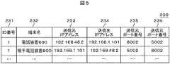
図5を参照して、RTPパケットアドレス変換テーブルを説明する。図5において、RTPパケットアドレス変換テーブル230は、ID番号231と、端末名232と、送信元IPアドレス233と、送信先IPアドレス234と、送信元ポート番号235と、送信先ポート番号236とを保持する。変換アドレス抽出部204は、RTPパケットアドレス変換テーブル230について、変換アドレス記憶部205に保持し、更新する。 The RTP packet address conversion table will be described with reference to FIG. 5, the RTP packet address conversion table 230 includes an
図3のINVITEおよび図4の200OKを受信すると、変換アドレス抽出部204は、INVITE210と200 OK210のコネクション情報:c241、221から、送信元IPアドレスを抽出し、INVITE210と、200 OK210のメディア情報:m242、222から、送信元ポート番号を抽出する。 Upon receiving the INVITE in FIG. 3 and the 200 OK in FIG. 4, the translated
そして、抽出したアドレスを対応付けて記憶する。本実施例では、わかりやすく説明するために、電話装置600および相手電話装置800それぞれの通話路について分けて説明する。 Then, the extracted addresses are stored in association with each other. In the present embodiment, for easy understanding, the telephone paths of the
図3および図5において、INVITEの送信元は、図1の電話装置600である。したがって、図5の最初のレコードのID番号231は、変換アドレス抽出部204が割り振った「1」である。端末名232は、「電話装置600」である。送信元IPアドレス233は、図示しないINVITEメッセージの送信元IPアドレス「192.168.48.2」、送信元ポート番号235は、図示しないINVITEメッセージ送信元ポート番号「8002」である。また、送信先IPアドレス234は、INVITEメッセージの図3のc欄241に記載された「192.168.1.101」である。さらに、送信先ポート番号236は、図3のm欄242に記載された「5002」である。 3 and 5, the source of INVITE is the
図4および図5において、200OKの送信元は、図1の相手電話装置800である。したがって、図5の最初のレコードのID番号231は、変換アドレス抽出部204が割り振った「1」である。端末名232は、「相手電話装置800」である。送信元IPアドレス233は、図示しない200OKメッセージの送信元IPアドレス「192.168.1.101」、送信元ポート番号235は、図示しない200OKメッセージ送信元ポート番号「5002」である。また、送信先IPアドレス234は、200OKメッセージの図3のc欄221に記載された「192.168.48.2」である。さらに、送信先ポート番号236は、図3のm欄222に記載された「8002」である。 4 and 5, the transmission source of 200 OK is the
尚本実施例では、SIPメッセージINVITEのContent−Typeno cおよびmを参照して相手のIPアドレスおよびポート番号を抽出し、RTPパケットのアドレス変換を行っているが本願はこれに限定しない。予め図3および図4のINVITEおよび200OKのFrom、toのみを監視し、From、toが一致する場合に、SIPメッセージの各送信元アドレスおよびポート番号を抽出し、変換テーブルに記憶してもよいし、RTPパケットのみを監視し、RTPパケットの送信元IPアドレスおよび送信元ポート番号並びに送信先IPアドレスおよび送信先ポート番号が双方向で通信を行っていることを検出し、アドレス変換してもよい。 In this embodiment, the other party's IP address and port number are extracted by referring to the Content-Type c and m of the SIP message INVITE, and the address conversion of the RTP packet is performed. However, the present invention is not limited to this. Only the INVITE and 200OK From and to of FIG. 3 and FIG. 4 are monitored in advance, and when From and to match, each source address and port number of the SIP message may be extracted and stored in the conversion table And monitoring only the RTP packet, detecting that the source IP address and source port number of the RTP packet and the destination IP address and destination port number are communicating bidirectionally, Good.
さらに、SIPメッセージがBYEであれば、BYEメッセージから通話に使用していた送信元IPアドレスおよび送信元ポート番号を抽出し、図5の送信元IPアドレスおよび送信元ポート番号または送信先IPアドレスおよび送信先ポート番号が対応するレコードを、RTPパケットアドレス変換テーブル230から削除する。 Further, if the SIP message is BYE, the source IP address and source port number used for the call are extracted from the BYE message, and the source IP address and source port number or destination IP address of FIG. The record corresponding to the transmission destination port number is deleted from the RTP packet address conversion table 230.
変換アドレス記憶部205は、RTPパケットアドレス変換テーブル230を記憶する。変換アドレス記憶部205は、変換アドレス抽出部204からの指示によりネットワークアドレスおよびポート番号情報の保存または削除を行なう。また、変換アドレス記憶部205は、RTPパケット抽出部204からの要求に従い、RTPパケットを判別するためのアドレス変換前のネットワークアドレスおよびポート番号情報を通知する。変換アドレス記憶部205は、さらに、RTPパケットアドレス変換部209からの要求に従い、RTPパケットのアドレス変換後のネットワークアドレスおよびポート番号情報を通知する。 The translation
変換アドレス抽出部204は、RTPパケットアドレス変換テーブル230について、通話毎にID番号231を付加して管理する。変換アドレス抽出部204は、INVITEよりINVITE送信側の送信元IPアドレスおよびポート番号を抽出し、INVITE受信側の送信先IPアドレスおよびポート番号と組み合わせて記憶する。また、変換アドレス抽出部204は、200 OKより200 OK送信側の送信元IPアドレスおよびポート番号を抽出し、200 OK受信側の送信先IPアドレスおよびポート番号と組み合わせて、記憶する。また、変換アドレス抽出部204は、該当する通話のBYEによりRTPパケットアドレス変換テーブル230から該当する通話IDのレコードを削除する。 The translation
ペイロード分離部207は、RTPパケット抽出部204からパケットデータを受信するとパケットのペイロード部分を抜き出してRTPパケットアドレス変換部209へと送信する。 When receiving the packet data from the RTP
RTPパケットアドレス変換部209は、ペイロード分離部207からパケットのペイロードデータおよびID番号を受け取ると、このペイロードデータを一時保存する。RTPパケットアドレス変換部209は、ID番号に対応したアドレス変換後のネットワークアドレスおよびポート番号情報を変換アドレス記憶部205より読み出し、一時保存したペイロードデータと合わせてパケットデータとして変換する。さらに、RTPパケットアドレス変換部209は、アドレス変換したRTPパケットをRTPパケット送信部208へ送信する。 When the RTP packet
変換RTPパケット送信部208は、RTPパケットアドレス変換部209より受信したパケットデータを接続インターフェース部201を介してLAN100へと送信する。
中継部210は、接続インターフェース部202より受信したパケットデータを接続インターフェース部201を介してLAN100へと送信する。The converted RTP
The
接続インターフェース部202は、ゲートウェイ300との接続部である。接続インターフェース部202は、RTPパケット抽出部206から受信したパケットデータをゲートウェイ300へと送信する。接続インターフェース部202は、またゲートウェイ300からパケットデータを受信すると中継部209へ送信する。 The
図6は、アドレス変換装置が行うRTPパケットのアドレス変換を模式的に説明する図である。図6において、電話装置600は、IPアドレスとして、192.168.48.2が、URIとして、itl@example1.comが割当てられている。また、待ち受けポート番号は、8002である。ゲートウェイ300は、IPアドレスとして、192.168.48.1.が割当てられている。また、ポート番号は、8002である。一方、相手電話装置800は、IPアドレスとして、192.168.1.101が、URIとして、nyc@example2.comが割当てられている。また、待ち受けポート番号は、5002である。 FIG. 6 is a diagram schematically illustrating address conversion of the RTP packet performed by the address conversion device. In FIG. 6, the
電話装置600は、ゲートウェイ300にnyc@example2.com宛のINVITEメッセージを送信する。図6(a)のINVITEメッセージのIPヘッダ部には、送信元IPアドレスとして、電話装置600のIPアドレス(192.168.48.2)、送信先IPアドレスとして、ゲートウェイ300のIPアドレス(192.168.48.1)が記載されている。また、UDPまたはTCPヘッダ部の送信元ポート番号は、電話装置600の待ち受けポート番号(8002)、送信先ポート番号は、ゲートウェイ300のポート番号(8002)を記載する。 The
ゲートウェイ300は、INVITEメッセージのIPヘッダ部の送信先IPアドレスを相手電話装置800のIPアドレス(192.168.1.101)に書き換える。ゲートウェイ300は、INVITEメッセージのUDPまたはTCPヘッダ部の送信先ポート番号を相手電話装置800の待ち受けポート番号(6002)に書き換える。
アドレス変換装置200は、電話装置600からゲートウェイ300へのRTPパケットの送信先IPアドレスと、送信先ポート番号をゲートウェイ300に代わって、図6(a)から図6(b)に書き換える。 The
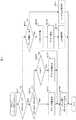
図7を参照して、アドレス変換装置の処理フローを説明する。図7において、処理フローは、アドレス変換装置がLAN100からSIPメッセージのパケットデータまたはRTPパケットデータを受信したところから開始される。アドレス変換装置200は、接続インターフェース部201でパケットデータを受信すると、パケットデータがSIPメッセージかどうか判定する(S401)。SIPメッセージのとき(YES)、アドレス変換装置200は、さらにSIPメッセージの内容がINVITE/200OKかを確認する(S402)。SIPメッセージがINVITE/200OKのとき(S402:YES)、アドレス変換装置200は、RTPパケットの抽出と変換に用いるアドレス情報(ネットワークアドレスおよびポート番号)を取得し、対応するID番号と共に変換アドレス記憶部205で記憶する(S403)。アドレス変換装置200は、SIPメッセージを接続インターフェース部211から送信して(S406)、終了する。 With reference to FIG. 7, the processing flow of the address translation apparatus will be described. In FIG. 7, the processing flow starts when the address translation device receives packet data or RTP packet data of a SIP message from the
ステップ402でINVITE/200 OKでないとき(NO)、アドレス変換装置200は、SIPメッセージの内容がS403で変換アドレス記憶部205に記憶させたINVITE/200 OKに対応するByeメッセージかどうかを確認する(S404)。SIPメッセージがINVITE/200 OKに対応するByeメッセージのとき(YES)、アドレス変換装置200は、アドレス情報(ネットワークアドレスおよびポート番号)と対応するID番号の情報を変換アドレス記憶部205より消去して(S405)、ステップ406に遷移する。ステップ404でNOのとき、そのままステップ406に遷移する。 When it is not INVITE / 200 OK in step 402 (NO), the
ステップ401でパケットデータがSIPメッセージでないとき(NO)(RTPパケットであった時)、アドレス変換装置200は、RTPパケットの送信元IPアドレスおよび送信元ポート番号と変換アドレス記憶部205に記憶されたアドレス情報(ネットワークアドレスおよびポート番号)との比較検出を行なう(S407)。記憶されたアドレス情報と一致が検出されたとき(YES)、アドレス変換装置200は、パケットデータからペイロード部分を分離する(S408)。アドレス変換装置200は、変換アドレス記憶部205に記憶されている一致したアドレス情報と同じレコードの変換後アドレス情報を読み出し、アドレス変換する(S409)。
アドレス変換されたパケットデータについて、アドレス変換装置200は、接続インターフェース部201よりLAN100側へ送信する(S410)。When the packet data is not a SIP message in step 401 (NO) (when it is an RTP packet), the
The
ステップ407で記憶されたアドレス情報と一致が検出されないとき(NO)、アドレス変換装置200は、当該パケットを接続インターフェース部210よりゲートウェイ側へ送信する(S411)。 When a match with the address information stored in
上述した実施例に拠れば、ゲートウェイの処理軽減により、パケット遅延または欠落が無く通信をすることが可能となる。
なお、上述した実施例ではアドレス変換装置をゲートウェイの外に設けたが、ゲートウェイに内蔵してもよい。According to the above-described embodiment, communication can be performed without any packet delay or omission due to the reduction of the gateway processing.
In the above-described embodiment, the address translation device is provided outside the gateway, but may be incorporated in the gateway.
100…LAN、200…アドレス変換装置、220…200 OKレスポンス、230…RTPパケットアドレス変換テーブル、240…INVITEリクエスト、300…ゲートウェイ、400…ルータ、500…外線ネットワーク、600…電話装置、700…情報端末、800…相手電話装置、900…SIPサーバ、1000…通信システム。 DESCRIPTION OF
Claims (2)
Translated fromJapanese前記内部ネットワークから前記ゲートウェイ装置へ中継する前記パケットデータのうち、呼制御に係るメッセージを監視するメッセージ監視手段と、
前記メッセージ監視手段が発呼または着呼に係るメッセージを検出すると、当該メッセージの送信元アドレスおよび送信元ポート番号並びに該メッセージに含まれる送信先アドレスおよび送信先ポート番号を呼IDと対応付けて記憶するアドレス記憶手段と、
前記内部ネットワークから前記ゲートウェイへ中継する前記パケットデータのうち、リアルタイムパケットデータを抽出するリアルタイムパケットデータ抽出手段と、
前記リアルタイムパケットデータ抽出手段が抽出したリアルタイムパケットデータの送信元アドレスおよび送信元ポート番号を取得し、前記取得した送信元アドレスおよび送信元ポート番号を検索キーとして前記アドレス記憶手段を検索するアドレス検索手段と、
一致する送信元アドレスおよび送信元ポート番号を検出したならば、前記抽出したリアルタイムパケットデータの送信先アドレスおよび送信先ポート番号を、アドレス検索手段が前記検出した送信元アドレスおよび送信元ポート番号に対応する送信先アドレスおよび送信先ポート番号に変換し、前記ゲートウェイ装置へ中継せずに前記内部ネットワークに送信するアドレス変換送信手段と、を有することを特徴とするアドレス変換装置。An address translation device that connects to a gateway device that performs address translation to communicate with an external network and an internal network, and relays packet data between the gateway device and the internal network,
Among the packet data relayed from the internal network to the gateway device, message monitoring means for monitoring a message related to call control;
When the message monitoring means detects a message related to an outgoing call or an incoming call, the source address and source port number of the message and the destination address and destination port number included in the message are stored in association with the call ID. Address storage means for
Real-time packet data extraction means for extracting real-time packet data out of the packet data relayed from the internal network to the gateway;
Address search means for acquiring a transmission source address and a transmission source port number of the real-time packet data extracted by the real-time packet data extraction means, and searching the address storage means using the acquired transmission source address and transmission source port number as a search key When,
If a matching source address and source port number are detected, the destination address and destination port number of the extracted real-time packet data correspond to the source address and source port number detected by the address search means. An address translation device comprising: address translation and transmission means for translating to a destination address and destination port number to be transmitted and transmitting to the internal network without relaying to the gateway device.
前記メッセージ監視手段が、当該発呼または着呼の通話終了に係るメッセージを検出すると、当該発呼の通話終了に係るメッセージの送信元アドレスおよび送信元ポート番号を取得し、前記取得した送信元アドレスおよび送信元ポート番号を検索キーとして前記アドレス記憶手段を検索し、一致する送信元アドレスおよび送信元ポート番号を検出したならば、当該一致する送信元アドレスおよび送信元ポート番号並びに当該一致する送信元アドレスおよび送信元ポート番号に対応する送信先アドレスおよび送信先ポート番号を消去するアドレス消去手段とをさらに有することを特徴とするアドレス変換装置。The address translation device according to claim 1,
When the message monitoring unit detects a message related to the call termination of the call or the call, the message monitoring unit acquires a source address and a source port number of the message related to the call termination of the call, and the acquired source address If the address storage means is searched using the source port number as a search key and a matching source address and source port number are detected, the matching source address and source port number and the matching source An address conversion device further comprising: an address erasing unit for erasing a transmission destination address and a transmission destination port number corresponding to the address and the transmission source port number.
Priority Applications (1)
| Application Number | Priority Date | Filing Date | Title |
|---|---|---|---|
| JP2009275689AJP2011120008A (en) | 2009-12-03 | 2009-12-03 | Address conversion apparatus |
Applications Claiming Priority (1)
| Application Number | Priority Date | Filing Date | Title |
|---|---|---|---|
| JP2009275689AJP2011120008A (en) | 2009-12-03 | 2009-12-03 | Address conversion apparatus |
Publications (1)
| Publication Number | Publication Date |
|---|---|
| JP2011120008Atrue JP2011120008A (en) | 2011-06-16 |
Family
ID=44284785
Family Applications (1)
| Application Number | Title | Priority Date | Filing Date |
|---|---|---|---|
| JP2009275689APendingJP2011120008A (en) | 2009-12-03 | 2009-12-03 | Address conversion apparatus |
Country Status (1)
| Country | Link |
|---|---|
| JP (1) | JP2011120008A (en) |
Citations (1)
| Publication number | Priority date | Publication date | Assignee | Title |
|---|---|---|---|---|
| JP2003174466A (en)* | 2001-12-07 | 2003-06-20 | Hitachi Ltd | Address translation device, message processing method and device |
- 2009
- 2009-12-03JPJP2009275689Apatent/JP2011120008A/enactivePending
Patent Citations (1)
| Publication number | Priority date | Publication date | Assignee | Title |
|---|---|---|---|---|
| JP2003174466A (en)* | 2001-12-07 | 2003-06-20 | Hitachi Ltd | Address translation device, message processing method and device |
Similar Documents
| Publication | Publication Date | Title |
|---|---|---|
| KR100765325B1 (en) | Symmetric Network Address Translation System Using STBN and Its Method | |
| US8650312B2 (en) | Connection establishing management methods for use in a network system and network systems using the same | |
| US8296447B2 (en) | Method for copying session information, call control server for executing the same, and computer product | |
| US20060193323A1 (en) | Apparatus and method for providing session initiation protocol (SIP) service in private network | |
| CN102111514B (en) | VoIP recording system and recording method | |
| WO2006082576A2 (en) | A method and apparatus for server-side nat detection | |
| US20130117460A1 (en) | Data management methods for use in a network system and network systems using the same | |
| JP2005236824A (en) | IPv6 / IPv4 translator | |
| JP2005229273A (en) | Server backup device | |
| JP4266188B2 (en) | COMMUNICATION SYSTEM, COMMUNICATION TERMINAL DEVICE USED IN THIS COMMUNICATION SYSTEM, AND COMMUNICATION METHOD USED IN COMMUNICATION SYSTEM | |
| US8656001B2 (en) | Communication system, application server and communication method for server cooperation | |
| US8130425B2 (en) | Methods and apparatus to route fax calls in an internet protocol (IP) multimedia subsystem (IMS) network | |
| US20100002701A1 (en) | System and method for media communication through network address translation | |
| JP2011147007A (en) | Speech recording apparatus and speech recording system | |
| CN103152495B (en) | A kind of method of media transfer, Apparatus and system | |
| CN101179491A (en) | Method, equipment, device and system for communication between internal terminals in private network | |
| US8194686B2 (en) | Communications relay device, program and method, and network system | |
| TWI255113B (en) | Method of media relay passing through Network Address Translation equipments to be decreased | |
| JP4541333B2 (en) | Terminal device, system, method, and program | |
| KR101666594B1 (en) | System and method for providing sip service | |
| JP2011120008A (en) | Address conversion apparatus | |
| CN104363149A (en) | SIP (session initiation protocol)-based system and method for achieving VOIP (voice over Internet protocol) network state monitoring | |
| JP2011071853A (en) | Ip telephone system, communication content recorder and communication method | |
| JP2010011120A (en) | Nat conversion apparatus and nat conversion program in uni connection | |
| JP4889617B2 (en) | Gateway apparatus and communication control method |
Legal Events
| Date | Code | Title | Description |
|---|---|---|---|
| A621 | Written request for application examination | Effective date:20121011 Free format text:JAPANESE INTERMEDIATE CODE: A621 | |
| A977 | Report on retrieval | Free format text:JAPANESE INTERMEDIATE CODE: A971007 Effective date:20130909 | |
| A131 | Notification of reasons for refusal | Effective date:20130917 Free format text:JAPANESE INTERMEDIATE CODE: A131 | |
| A131 | Notification of reasons for refusal | Free format text:JAPANESE INTERMEDIATE CODE: A131 Effective date:20131224 | |
| A02 | Decision of refusal | Effective date:20140507 Free format text:JAPANESE INTERMEDIATE CODE: A02 |