Movatterモバイル変換


[0]ホーム

URL:


JP2011117261A - Faucet - Google Patents

Faucet
Download PDF

Info

Publication number
JP2011117261A
JP2011117261AJP2010001025AJP2010001025AJP2011117261AJP 2011117261 AJP2011117261 AJP 2011117261AJP 2010001025 AJP2010001025 AJP 2010001025AJP 2010001025 AJP2010001025 AJP 2010001025AJP 2011117261 AJP2011117261 AJP 2011117261A
Authority
JP
Japan
Prior art keywords
tube
outer tube
faucet
water discharge
pipe
Prior art date
Legal status (The legal status is an assumption and is not a legal conclusion. Google has not performed a legal analysis and makes no representation as to the accuracy of the status listed.)
Granted
Application number
JP2010001025A
Other languages
Japanese (ja)
Other versions
JP5604113B2 (en
Inventor
美保 ▲くわ▼田
Miho Kuwata
Atsushi Imai
敦司 今井
Current Assignee (The listed assignees may be inaccurate. Google has not performed a legal analysis and makes no representation or warranty as to the accuracy of the list.)
Kakudai Mfg Co Ltd
Original Assignee
Kakudai Mfg Co Ltd
Priority date (The priority date is an assumption and is not a legal conclusion. Google has not performed a legal analysis and makes no representation as to the accuracy of the date listed.)
Filing date
Publication date
Application filed by Kakudai Mfg Co LtdfiledCriticalKakudai Mfg Co Ltd
Priority to JP2010001025ApriorityCriticalpatent/JP5604113B2/en
Publication of JP2011117261ApublicationCriticalpatent/JP2011117261A/en
Application grantedgrantedCritical
Publication of JP5604113B2publicationCriticalpatent/JP5604113B2/en
Activelegal-statusCriticalCurrent
Anticipated expirationlegal-statusCritical

Links

Images

Landscapes

Abstract

Translated fromJapanese

【課題】外観的に優れ、疲労、摩擦等による漏水を来す心配の無い水栓を提供する。
【解決手段】水栓は、水栓本体11と、水栓本体11から吐水するための吐水パイプ12とを備えている。吐水パイプ12は、内外二重構造の外管41および内管42を有している。外管41の先端部に着脱自在に取付られている。内管42の基端部が水栓本体11に、その先端部が吐水ヘッド43にそれぞれ通水可能に接続されている。外管41は、剛性を有している。内管42は、撓性を有している。外管41の周方向の一部に、外管軸方向にのびかつ先端開放スリット51が形成されている。外管41の先端部から吐水ヘッド43を取外した状態で、内管42の撓みにともない、スリット51を通じて、外管41から内管42が引出し可能である。
【選択図】図1
Provided is a faucet that is excellent in appearance and does not have to worry about water leakage due to fatigue, friction, or the like.
A faucet includes a faucet body and a water discharge pipe for discharging water from the faucet body. The water discharge pipe 12 has an outer tube 41 and an inner tube 42 having an inner / outer double structure. The outer tube 41 is detachably attached to the distal end portion. The proximal end portion of the inner pipe 42 is connected to the faucet body 11 and the distal end portion thereof is connected to the water discharge head 43 so as to allow water to pass therethrough. The outer tube 41 has rigidity. The inner tube 42 has flexibility. A part of the outer tube 41 in the circumferential direction is formed with a slit 51 that opens in the axial direction of the outer tube and has a distal end. With the water discharge head 43 removed from the tip of the outer tube 41, the inner tube 42 can be pulled out from the outer tube 41 through the slit 51 as the inner tube 42 is bent.
[Selection] Figure 1

Description

Translated fromJapanese

この発明は、水栓、とくに、シャワーヘッド等の先端吐水部の位置を任意に変更できるようにした水栓に関する。  The present invention relates to a faucet, and more particularly to a faucet that can arbitrarily change the position of a tip water discharger such as a shower head.

この種の水栓としては、吐水パイプがフレキシブルパイプによって構成されており、吐水パイプの先端にシャワーヘッドが取付られているものが知られている。  As this type of faucet, there is known a faucet in which a water discharge pipe is constituted by a flexible pipe, and a shower head is attached to the tip of the water discharge pipe.

この水栓では、シャワーヘッドの重みで吐水パイプが垂れ下がることがあった。そのため、吐水パイプの付け根が金属疲労等によって破損する恐れがあった。さらに、フレキシブルパイプ露出しているため、見た目が悪かった。  In this faucet, the water discharge pipe sometimes hangs down due to the weight of the shower head. Therefore, the base of the water discharge pipe may be damaged due to metal fatigue or the like. Furthermore, because the flexible pipe was exposed, it looked bad.

他の水栓としては、吐水パイプが、螺旋管およびインナーチューブよりなる撓性ホースによって構成されており、吐水パイプを、U字状に屈曲させた状態で、シンク裏側等のスペースに引出可能に収納し、引出口を通じて吐水パイプを引出して使用するようにしたものが知られている。  As another faucet, the water discharge pipe is composed of a flexible hose made of a spiral tube and an inner tube, and the water discharge pipe can be pulled out to a space on the back side of the sink or the like with the water discharge pipe bent in a U shape. What is stored and used to draw out a water discharge pipe through a pull-out port is known.

この水栓では、吐水パイプの引入・引出時に、吐水パイプが引出口縁部との摩擦等によって損傷し、漏水を起こす恐れがあった。漏水を起こした場合、吐水パイプの、スペース内にある部分はメンテナンスが容易ではない。さらに、漏水によってフローリングが損害を受けると、その損害による経済的負担が大であった。  In this faucet, when the water discharge pipe is drawn in and pulled out, the water discharge pipe may be damaged due to friction with the edge of the outlet and may cause water leakage. When water leaks, the part of the water discharge pipe in the space is not easy to maintain. Furthermore, when the flooring is damaged by water leakage, the economic burden due to the damage was large.

この発明の目的は、外観的に優れ、疲労、摩擦等による漏水を来す心配の無い水栓を提供することにある。  An object of the present invention is to provide a faucet which is excellent in appearance and has no fear of causing water leakage due to fatigue, friction or the like.

この発明による水栓は、水栓本体と、水栓本体から吐水するための吐水パイプとを備えており、吐水パイプは、内外二重構造の外管および内管を有しており、外管の先端部に吐水ヘッドが着脱自在に取付られており、内管の基端部が水栓本体に、その先端部が吐水ヘッドにそれぞれ通水可能に接続されており、外管は、剛性を有しており、内管は、撓性を有しており、外管の周方向の一部に、外管軸方向にのびかつ先端開放スリットが形成されており、外管の先端部から吐水ヘッドを取外した状態で、内管の撓みにともない、スリットを通じて、外管から内管が引出し可能であるものである。  The faucet according to the present invention includes a faucet body and a water discharge pipe for discharging water from the faucet body, and the water discharge pipe has an outer tube and an inner tube having a double structure inside and outside, and the outer tube. The water discharge head is detachably attached to the distal end of the inner tube, the proximal end of the inner tube is connected to the faucet body, and the distal end is connected to the water discharge head so that water can pass through. The inner tube has flexibility, and a slit extending in the axial direction of the outer tube is formed in a part of the outer tube in the circumferential direction, and water is discharged from the distal end portion of the outer tube. With the head removed, the inner tube can be pulled out from the outer tube through the slit as the inner tube bends.

この発明による水栓では、撓性内管の先端部が吐水ヘッドを介して剛性外管によって支持されるから、内管がその重みで垂れ下がる心配が無い。さらに、外管内の内管は、外管の内面にそう伸張状態であり、引出時には、スリットを通じて、内管の撓みによって、その半径方向に引出されるため、外管に対する内管の摩擦を可及的に低減することができ、摩擦等によって、内管が損傷して漏水することを防止できる。  In the faucet according to the present invention, since the distal end portion of the flexible inner tube is supported by the rigid outer tube via the water discharge head, there is no fear that the inner tube hangs down due to its weight. Furthermore, the inner tube in the outer tube is stretched to the inner surface of the outer tube, and when pulled out, the inner tube is pulled out through the slit by the bending of the inner tube in the radial direction. As a result, the inner pipe can be prevented from being damaged and leaking due to friction or the like.

さらに、外管の少なくとも一部に、外向き凸状屈曲部が設けられており、スリットは、屈曲部の内面側をのびていると、外管の屈曲部に内管がそわされた状態では、内管の自重による撓みを防止することができ、引出に際しては、内管の先端側から順次引出されるため、スリットから内管をスムースに引出ことができる。  Further, at least a part of the outer tube is provided with an outward convex bent portion, and when the slit extends on the inner surface side of the bent portion, in a state where the inner tube is deflected to the bent portion of the outer tube, The inner tube can be prevented from being bent due to its own weight, and when being pulled out, the inner tube is sequentially pulled out from the distal end side of the inner tube, so that the inner tube can be smoothly pulled out from the slit.

また、外管および内管の基端部は、外管および内管の対応する軸線周りにそれぞれ回転自在に水栓本体に支持されていると、吐水ヘッドの位置を、水平面内に自在に変更することができ、便利である。  In addition, if the base end of the outer tube and inner tube are supported by the faucet body so as to be rotatable around the corresponding axis of the outer tube and inner tube, the position of the water discharge head can be freely changed within the horizontal plane. Can be convenient.

また、外管および内管の先端部と、吐水ヘッドとは、外管および内管の対応する軸線周りにそれぞれ相対回転自在であると、吐水ヘッドの向きを、吐水ヘッドが外管の先端部に取付られているか、否かに関わりなく、その軸線の周りまわりに自在に回転させることができる。  Further, when the distal end of the outer tube and the inner tube and the water discharge head are relatively rotatable around corresponding axes of the outer tube and the inner tube, respectively, the direction of the water discharge head is determined. Regardless of whether it is attached to or not, it can be freely rotated around its axis.

また、スリットにカバーが被覆されており、カバーは、スリット長手方向にのびかつ相対させた縁部を有する一対のカバー半体を備えており、各カバー半体は、撓み性を有しており、各カバー半体の撓みにともない、同両縁部間を、内管が通過可能であるから、外管内の内管は、カバーによって隠されることになり、内管を保護することができ、同時に、吐水パイプの美観を向上させることがてきる。  In addition, the cover is covered with the slit, and the cover includes a pair of cover halves having edges that extend in the slit longitudinal direction and face each other, and each cover half has flexibility. The inner tube can pass between the edges of the cover halves, so the inner tube in the outer tube is hidden by the cover, and the inner tube can be protected. At the same time, the beauty of the water discharge pipe can be improved.

また、外管が、その長さ方向において、スリットの無い閉鎖管部およびスリットの有る開放管部に区画されており、開放管部において、スリットを除いて、内管を取囲む部分が、内管保護用合成樹脂によって形成されていると、外管に対する内管の接触による損傷を防止することができる。  In addition, the outer tube is divided in the length direction into a closed tube portion without a slit and an open tube portion with a slit. In the open tube portion, the portion surrounding the inner tube excluding the slit is If it is formed of a synthetic resin for protecting a tube, damage due to contact of the inner tube with the outer tube can be prevented.

また、外管の先端部に吐水ヘッドが取付られた状態で、外管の先端部に差込解除自在に差込まれかつ内管を通した差込筒部が吐水ヘッドに設けられており、差込筒部の周壁に、差込筒部の差込解除方向の移動を規制するためのストッパが設けられており、ストッパは、差込筒部の外面に対して出入自在であり、外管の先端部内面に、出入するストッパを進退させうる凹所が形成されており、凹所に対するストッパの進退によって、ストッパが作動・解除しうるようになされていると、外管に対する吐水ヘッドの着脱を容易に行うことがき、同時に、外管に吐水ヘッドが取付られた状態で、吐水ヘッドの不用意な脱落を防止することができる。  In addition, with the water discharge head attached to the distal end portion of the outer tube, the water discharge head is provided with an insertion tube portion inserted into the distal end portion of the outer tube so as to be freely releasable and passed through the inner tube, A stopper is provided on the peripheral wall of the insertion tube portion to restrict the movement of the insertion tube portion in the insertion release direction. The stopper can be moved in and out of the outer surface of the insertion tube portion. On the inner surface of the tip, there is a recess that allows the stopper to be moved in and out, so that the stopper can be operated and released by the movement of the stopper relative to the recess. At the same time, it is possible to prevent inadvertent dropping of the water discharge head with the water discharge head attached to the outer tube.

この発明によれば、外観的に優れ、疲労、摩擦等による漏水を来す心配の無い水栓が提される。  According to the present invention, there is provided a faucet which is excellent in appearance and has no fear of causing water leakage due to fatigue, friction or the like.

この発明による水栓の破砕断面を含む側面図である。It is a side view containing the crushing cross section of the faucet by this invention.同水栓の水栓本体部周辺を示す垂直縦断面図である。It is a vertical longitudinal cross-sectional view which shows the faucet body part periphery of the faucet.同水栓の外管基端部を示す斜視図である。It is a perspective view which shows the outer pipe base end part of the same faucet.同水栓の外管先端部および吐水ヘッドを示す分解斜視図である。It is a disassembled perspective view which shows the outer tube | pipe front-end | tip part and water discharging head of the same faucet.図4に示す部分の垂直縦断面図である。It is a vertical longitudinal cross-sectional view of the part shown in FIG.図5のV−V線にそう水平縦断面図である。FIG. 6 is a horizontal longitudinal sectional view taken along line VV in FIG. 5.他の実施例による水栓を示す図2相当の垂直縦断面図である。It is the vertical longitudinal cross-sectional view equivalent to FIG. 2 which shows the water tap by another Example.さらに他の実施例による水栓を示す図1相当の側面図である。It is a side view equivalent to FIG. 1 which shows the water tap by other Example.図8に示す水栓の拡大横断面図である。FIG. 9 is an enlarged cross-sectional view of the water faucet shown in FIG. 8.図8に示す水栓の変形例を示す図9相当の拡大横断面図である。FIG. 10 is an enlarged cross-sectional view corresponding to FIG. 9 showing a modification of the faucet shown in FIG. 8.図8に示す水栓の他の変形例を示す図9相当の拡大横断面図である。FIG. 10 is an enlarged cross-sectional view corresponding to FIG. 9 showing another modification of the faucet shown in FIG. 8.同水栓の外管の変形例を示す斜視図である。It is a perspective view which shows the modification of the outer tube | pipe of the same faucet.図12に示す外管の拡大横断面図である。FIG. 13 is an enlarged cross-sectional view of the outer tube shown in FIG. 12.図13に示す外管の変形例を示す拡大横断面図である。FIG. 14 is an enlarged cross-sectional view showing a modification of the outer tube shown in FIG. 13.同水栓の外管の他の変形例を示す斜視図である。It is a perspective view which shows the other modification of the outer tube | pipe of the same faucet.同水栓の外管のさらなる他の変形例を示す斜視図である。It is a perspective view which shows the further another modification of the outer tube | pipe of the same faucet.同水栓の外管に対する吐水ヘッドの取付構造の変形例を示す図4相当の分解斜視図である。It is a disassembled perspective view equivalent to FIG. 4 which shows the modification of the attachment structure of the water discharging head with respect to the outer tube | pipe of the same faucet.同取付構造の他の変形例を示す図4相当の分解斜視図である。It is a disassembled perspective view equivalent to FIG. 4 which shows the other modification of the attachment structure.同取付構造の要部拡大断面図である。It is a principal part expanded sectional view of the attachment structure.同取付構造のさらなる他の変形例を示す図4相当の分解斜視図である。It is a disassembled perspective view equivalent to FIG. 4 which shows the further another modification of the same attachment structure.外管に対する吐水ヘッドのアタッチメントを示す斜視図である。It is a perspective view which shows the attachment of the water discharging head with respect to an outer tube | pipe.同アタッチメントの変形例を示す斜視図である。It is a perspective view which shows the modification of the attachment.

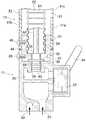
図1を参照すると、水栓は、湯水混合栓であって、水栓本体11と、水栓本体11から吐水するための吐水パイプ12とを備えている。  Referring to FIG. 1, the faucet is a hot and cold water mixing faucet, and includes afaucet body 11 and awater discharge pipe 12 for discharging water from thefaucet body 11.

水栓本体11は、図2に詳細に示すように、互いに並行して上向きにのびている冷水ポート21および湯水ポート22を有している。冷水ポート21および湯水ポート22の上端は、ミキシングカートリッジ23に接続されている。ミキシングカートリッジ23は、操作ハンドル24を有しかつ混合水チャンバ25に連通させられている。混合水チャンバ25の頂壁には給水口26が設けられている。給水口26を取り囲んで、混合水チャンバ25の頂壁には上方突出垂直筒状ソケット27が設けられている。ソケット27の周壁外側には抜止ボルト28が貫通状にねじ込まれている。  As shown in detail in FIG. 2, thefaucet body 11 has acold water port 21 and ahot water port 22 that extend upward in parallel with each other. The upper ends of thecold water port 21 and thehot water port 22 are connected to themixing cartridge 23. Themixing cartridge 23 has anoperation handle 24 and communicates with themixing water chamber 25. Awater supply port 26 is provided on the top wall of the mixedwater chamber 25. A verticallycylindrical socket 27 protruding upward is provided on the top wall of the mixedwater chamber 25 so as to surround thewater supply port 26. Aretaining bolt 28 is screwed in a penetrating manner on the outer peripheral wall of thesocket 27.

ソケット27には垂直筒状ロータリコネクタ31の下部がはめ入れられている。コネクタ31外面の下端寄りの部分には、抜止ボルト28の先端部をはめ入れた環状ガイド溝32がコネクタ31の軸線周りの回転を自在とするように形成されている。コネクタ31内面の下端寄りの部分には縮径部33が設けられている。縮径部33を挟んでその上側に上部段付孔34が、その下側に下部段付孔35がそれぞれ形成されている。  Thesocket 27 is fitted with the lower part of the vertical cylindricalrotary connector 31. An annular guide groove 32 into which the tip end portion of theretaining bolt 28 is fitted is formed in a portion near the lower end of the outer surface of theconnector 31 so as to freely rotate around the axis of theconnector 31. A reduceddiameter portion 33 is provided in a portion near the lower end of the inner surface of theconnector 31. An upper steppedhole 34 is formed on the upper side of the reduceddiameter portion 33, and a lower steppedhole 35 is formed on the lower side thereof.

吐水パイプ12は、内外二重構造の外管41および内管42と、外管41の先端部に着脱自在に取付られかつ内管42の先端部に通水可能に接続されている吐水ヘッド43とよりなる。  Thewater discharge pipe 12 includes anouter tube 41 and aninner tube 42 having an inner / outer double structure, and awater discharge head 43 that is detachably attached to the distal end portion of theouter tube 41 and is connected to the distal end portion of theinner tube 42 so as to allow water to pass therethrough. And more.

外管41は、横断面方形状鋼管を略逆L字状に屈曲したもので、上向き凸のアーチ状屈曲部41Wを有しかつ内壁41a、外壁41bおよび左右一対の側壁41cよりなる。  Theouter tube 41 is obtained by bending a steel pipe having a transverse cross section into a substantially inverted L shape, and has an upwardly projecting arch-shapedbent portion 41W and includes aninner wall 41a, anouter wall 41b, and a pair of left andright side walls 41c.

外管41の基端部において、ソケット27上端面および外管41基端面がスリップワッシャ44を介して重ね合わされるように外管41の基端部がコネクタ31の上方突出部にはめ被せられている。この状態で、外管41の内外両側壁41a、41bがコネクタ31の上方突出部を内外から挟んでいる。外管41外壁41bおよびコネクタ31の重ねあわされた部分は、止めボルト45によって固定されている。  At the base end portion of theouter tube 41, the base end portion of theouter tube 41 is fitted over the upper protruding portion of theconnector 31 so that the upper end surface of thesocket 27 and the base end surface of theouter tube 41 are overlapped via theslip washer 44. Yes. In this state, the inner andouter side walls 41a and 41b of theouter tube 41 sandwich the upward projecting portion of theconnector 31 from the inside and outside. The overlapped portion of theouter wall 41b of theouter tube 41 and theconnector 31 is fixed by aset bolt 45.

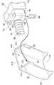
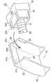
図1に加えて、図4を参照すると、外管41内壁41aの先端から基端近くにかけて、内壁41aのほぼ全体が除去され、これにより、外管41に先端開放スリット51が形成されている。スリット51の左右両縁部開放端には一対のガイド52が左右対向突出状に形成されている。外壁41b内面の先端近くには一対の円形状窪み53が形成されている。これらのガイド52および窪み53を含む外管41の先端部が嵌合凹部54を形成している。  Referring to FIG. 4 in addition to FIG. 1, almost the entireinner wall 41a is removed from the distal end of theinner wall 41a of theouter tube 41 to the vicinity of the proximal end, whereby a distal end opening slit 51 is formed in theouter tube 41. . A pair ofguides 52 are formed on the left and right edge open ends of theslit 51 so as to protrude left and right. A pair ofcircular recesses 53 are formed near the tip of the inner surface of theouter wall 41b. A distal end portion of theouter tube 41 including theguide 52 and therecess 53 forms afitting recess 54.

内管42は、螺旋鋼管製撓みホース61と、撓みホース61内に挿入されて、基端部および先端部を撓みホース61外にそれぞれ突出させている弾性材製通水ホース62とよりなる。  Theinner pipe 42 includes a helical steel pipe-madeflexible hose 61 and an elastic material water-permeable hose 62 that is inserted into theflexible hose 61 and has a proximal end portion and a distal end portion protruding from theflexible hose 61, respectively.

撓みホース61の基端部は、上部段付孔34内に相対回転自在に挿入されている。通水ホース62の基端部には基端パイプ63がかしめ止められている。基端パイプ63外面の長さの中程には鍔64が設けられている。この鍔64が下部段付孔35内に挿入されて、混合水チャンバ25頂壁の頂面および下部段付孔35底面で挟まれ、これにより、通水ホース62の基端部の抜け止めが果たされている。この状態で、基端パイプ63の、鍔64より上方部分が縮径部33に通され、その下方部分が給水口26に通されている。  The base end portion of theflexible hose 61 is inserted into the upper steppedhole 34 so as to be relatively rotatable. Aproximal pipe 63 is caulked to the proximal end of thewater flow hose 62. Aflange 64 is provided in the middle of the length of the outer surface of theproximal end pipe 63. Thistrough 64 is inserted into thelower step hole 35 and is sandwiched between the top surface of the top wall of themixed water chamber 25 and the bottom surface of thelower step hole 35, thereby preventing the base end of thewater flow hose 62 from coming off. Has been fulfilled. In this state, a portion of thebase end pipe 63 that is above theflange 64 is passed through the reduceddiameter portion 33, and a lower portion thereof is passed through thewater supply port 26.

図5および図6を参照すると、通水ホース62の先端部には先端パイプ65がかしめ止められている。先端パイプ65は、基端パイプ63と同じ構造のもので、外面に鍔66を有している。  Referring to FIGS. 5 and 6, atip pipe 65 is caulked to the tip of thewater hose 62. Thedistal end pipe 65 has the same structure as theproximal end pipe 63 and has aflange 66 on the outer surface.

吐水ヘッド43は、下向き吐水口71を有するヘッド本体72と、ヘッド本体72から一側方に突出状に設けられかつ嵌合凹部54に出入自在に差し込まれている略直方体状差込ブロック73とよりなる。差込ブロック73は、嵌合凹部54内面と合致させられた周面を有し、嵌合凹部54に対応する嵌合凸部を形成している。  Thewater discharge head 43 includes a headmain body 72 having a downwardwater discharge port 71, a substantially rectangularparallelepiped insertion block 73 that is provided so as to protrude from the headmain body 72 to one side and is inserted into thefitting recess 54 so as to freely enter and exit. It becomes more. Theinsertion block 73 has a peripheral surface matched with the inner surface of thefitting recess 54, and forms a fitting projection corresponding to thefitting recess 54.

ヘッド本体72には、吐水口軸線と直交する方向にのびかつ吐水口71に連通させられた連通ポート74が形成されている。連通ポート74の開口縁部には段付孔75が形成されている。  The headmain body 72 is formed with acommunication port 74 that extends in a direction orthogonal to the water discharge port axis and communicates with thewater discharge port 71. A steppedhole 75 is formed at the opening edge of thecommunication port 74.

差込ブロック73には、連通ポート74と一直線上に連通させられたホース孔81が形成されている。ホース孔81の長さの中程には縮径部82が設けられている。縮径部82よりも置くであって、ホース孔81の基部に連通させられるように下方開放部83が形成されている。  Theinsertion block 73 is formed with ahose hole 81 communicating with thecommunication port 74 in a straight line. A reduceddiameter portion 82 is provided in the middle of the length of thehose hole 81. A loweropen part 83 is formed so as to be placed more than the reduceddiameter part 82 and communicate with the base part of thehose hole 81.

ホース孔81の縮径部82より先端側には、撓みホース61の先端部が相対回転自在に挿入されている。先端パイプ65の鍔66より先端側が連通ポート74に挿入され、その鍔66は、段付孔75内に挿入されている。下方開放部83には略逆U字状固定具84が挿入されている。固定具84の平行線状部によって、段付孔75とは反対側から鍔66が押さえられ、これにより、通水ホース62先端部の抜け止めが果たされている。  The distal end portion of theflexible hose 61 is inserted in a relatively rotatable manner on the distal end side of the reduceddiameter portion 82 of thehose hole 81. A distal end side of thedistal end pipe 65 from theflange 66 is inserted into thecommunication port 74, and theflange 66 is inserted into the steppedhole 75. A substantially invertedU-shaped fixture 84 is inserted into thelower opening 83. By the parallel linear portion of thefixture 84, theflange 66 is pressed from the side opposite to the steppedhole 75, thereby preventing the tip of thewater hose 62 from coming off.

差込ブロック73の頂面には、両窪み53にはめ入れられた一対のストッパ91が備えられている。両ストッパ91は、連通ポート74を挟んでその両側を互いに平行にのびた一対の上下貫通状ばね孔92の上端開口縁部に進退自在に保持されかつ同ばね孔92に挿入された圧縮コイルばね93によって進出側に付勢されている。  On the top surface of theinsertion block 73, a pair ofstoppers 91 fitted in bothdepressions 53 are provided. Bothstoppers 91 arecompression coil springs 93 movably held at the upper end opening edges of a pair of upper and lower penetrating spring holes 92 extending parallel to each other across thecommunication port 74 and inserted into the spring holes 92. Is urged by the advance side.

差込ブロック73の両側面および底面の交差する部分にそって、一対のガイド溝94がそれぞれ形成されている。各ガイド溝94は、外管41の対応する側のガイド52と外管41軸方向にスライド自在にはめ合わされている。  A pair ofguide grooves 94 are formed along portions where both side surfaces and the bottom surface of theinsertion block 73 intersect. Eachguide groove 94 is slidably fitted in the axial direction of theouter tube 41 with theguide 52 on the corresponding side of theouter tube 41.

水栓の使用に際し、外管41に吐出ヘッド43を取付けた状態で、外管41の内面に内管42がそわされ、外管41の屈曲部41Aにそって内管42もアーチ状に屈曲させられている。この内管42のアーチ状屈曲部により、内管42の保形性が保たれる。ガイド52およびガイド溝94のはめ合いによって、外管41から吐出ヘッド43が不用意に取外される心配は、無い。操作ハンドル24によって、冷水、湯水またはこれらの混合水が吐出口71から吐出され、また、吐出停止される。外管41の押動によって、外管41とともにコネクタ31が回転させられ、コネクタ31とともに内管42が外管41と同時に回転させられる。  When using the faucet, with thedischarge head 43 attached to theouter tube 41, theinner tube 42 is deflected to the inner surface of theouter tube 41, and theinner tube 42 is also bent in an arch shape along thebent portion 41A of theouter tube 41. It has been made. Due to the arcuate bent portion of theinner tube 42, the shape retention of theinner tube 42 is maintained. There is no fear that thedischarge head 43 is inadvertently removed from theouter tube 41 due to the fitting of theguide 52 and theguide groove 94. Cold water, hot water, or a mixed water thereof is discharged from thedischarge port 71 by theoperation handle 24, and the discharge is stopped. By pushing theouter tube 41, theconnector 31 is rotated together with theouter tube 41, and theinner tube 42 is rotated simultaneously with theouter tube 41 together with theconnector 31.

吐出ヘッド43を手前側に引っ張り、嵌合凹部54から差込ブロック73を引出せば、外管41から吐出ヘッド43が取外される。この場合、窪み53からストッパ91が抜き出され、ガイド52にそってガイド溝94がスライドさせられ、吐出ヘッド43がスムースに移動させられる。外管41から吐出ヘッド43が取外された状態で、吐出ヘッド43をさらに手前に引っ張ると、吐出ヘッド43の移動にともない、外管41から内管42がその撓性によってスムースに引出される。逆の手順によって、外管41内に内管42が収納される。  When theejection head 43 is pulled toward the front side and theinsertion block 73 is pulled out from thefitting recess 54, theejection head 43 is removed from theouter tube 41. In this case, thestopper 91 is extracted from therecess 53, theguide groove 94 is slid along theguide 52, and thedischarge head 43 is smoothly moved. When thedischarge head 43 is pulled further forward with thedischarge head 43 removed from theouter tube 41, theinner tube 42 is smoothly pulled out of theouter tube 41 due to its flexibility as thedischarge head 43 moves. . Theinner tube 42 is accommodated in theouter tube 41 by the reverse procedure.

そして、以下に、上記水栓の様々なバリエーションを説明する。以下の説明において、上記した部分と対応するカ所には、同一の符号を付し、重複説明は、省略するものとする。  In the following, various variations of the faucet will be described. In the following description, parts corresponding to those described above are denoted by the same reference numerals, and redundant description is omitted.

図7には、一般的なJIS規格水栓の水栓本体111が示されている。この水栓本体111のソケット111A外面には雄ねじ112が形成されている。ソケット111A内面の段113の上には環状Uパッキン114が載置されている。このUパッキン114は、JIS規格によれば、パッキン押さえによって押さえられることになるが、この例では、筒状ホース受金具115によって押さえられている。ホース受金具115には、通水ホース62の基端パイプ63が回転自在にはめ入れられている。ホース受金具115の外面上端部には、水栓本体111上端面で受けられたフランジ116が設けられている。フランジ116上には、図2に示すコネクタ31とは別構造のロータリコネクタ117が載置されている。コネクタ117の内面下部には縮径部118が設けられている。コネクタ117内面の縮径部118上方に撓みホース61の基端部が回転自在にはめ入れられている。通水ホース62の基端部は、縮径部118を介してホース受金具115まで達している。コネクタ117外面下端部にはフランジ119が設けられている。ホース受金具115およびコネクタ117のフランジ116、119同士を重ね合わせた状態で、これを、雄ねじ112にねじはめられた押さえナット121によって緩く締付けている。外管41は、コネクタ117に止ねじ122によって固定されている。  FIG. 7 shows afaucet body 111 of a general JIS standard faucet. Amale screw 112 is formed on the outer surface of thesocket 111A of thefaucet body 111. Anannular U-packing 114 is placed on thestep 113 on the inner surface of thesocket 111A. According to the JIS standard, the U packing 114 is pressed by a packing presser. In this example, the U packing 114 is pressed by acylindrical hose bracket 115. In thehose bracket 115, theproximal end pipe 63 of thewater flow hose 62 is rotatably fitted. Aflange 116 received at the upper end surface of thefaucet body 111 is provided at the upper end portion of the outer surface of thehose bracket 115. On theflange 116, arotary connector 117 having a structure different from that of theconnector 31 shown in FIG. A diameter-reducedportion 118 is provided at the lower inner surface of theconnector 117. The base end portion of theflexible hose 61 is rotatably inserted above the reduceddiameter portion 118 on the inner surface of theconnector 117. The proximal end portion of thewater flow hose 62 reaches thehose receiving bracket 115 through the reduceddiameter portion 118. Aflange 119 is provided at the lower end of the outer surface of theconnector 117. In a state where thehose bracket 115 and theflanges 116 and 119 of theconnector 117 are overlapped with each other, they are loosely tightened by a holdingnut 121 screwed onto themale screw 112. Theouter tube 41 is fixed to theconnector 117 with aset screw 122.

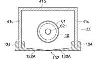
図8および図9を参照すると、外管41に、カバーベース131と、カバーベース131と一体化されかつスリット51に被覆されている目隠し用カバー132とが備えられている。  Referring to FIGS. 8 and 9, theouter tube 41 is provided with acover base 131 and ablindfold cover 132 integrated with thecover base 131 and covered with theslit 51.

カバーベース131およびカバー132は、軟質合成樹脂によって、全体として、屈曲状角筒体をなして、スリット51を除いて、外管41の内面に止ねじ133によって密着状に固定されている。  Thecover base 131 and thecover 132 are made of a soft synthetic resin to form a bent rectangular tube as a whole, and are fixed in close contact with the inner surface of theouter tube 41 by aset screw 133 except for theslit 51.

カバーベース131は、外管41の外壁41bおよび両側壁41cに対応して、横断面コ字状をなしている。  Thecover base 131 has a U-shaped cross section corresponding to theouter wall 41b and bothside walls 41c of theouter tube 41.

カバー132は、スリット51を含めて、外管41の内壁41aに対応しかつカバーベース131の両開口縁部に先端縁部同士を相対させるように連なる一対の平板状カバー半体132Aよりなる。  Thecover 132 includes a pair of flatplate cover halves 132A that include theslit 51 and that correspond to theinner wall 41a of theouter tube 41 and that are continuous with the opening edges of thecover base 131 facing each other.

外管41に吐水ヘッド43が取付られた状態では、内管42は、カバー132に隠されていて、内管42を外から見ることはできない。  In a state where thewater discharge head 43 is attached to theouter tube 41, theinner tube 42 is hidden by thecover 132, and theinner tube 42 cannot be seen from the outside.

外管41から吐水ヘッド43を取外し、スリット51から内管42を引出す場合、内管42が両カバー半体132Aの先端対向縁部を押動し、各カバー半体132Aの撓みによって、その押動部分が拡げられて、その拡げられた部分を内管42が通過させられる。  When thewater discharge head 43 is removed from theouter tube 41 and theinner tube 42 is pulled out from theslit 51, theinner tube 42 pushes the edges of the opposite ends of the cover halves 132A, and the cover halves 132A are bent to push them. The moving portion is expanded, and theinner tube 42 is allowed to pass through the expanded portion.

図10に、カバー132の別の態様が示されている。この態様のカバー132では、各カバー半体132Aの基部に、これと一体的に横断面略U字状挟持部134が設けられている。各カバー半体132Aの挟持部134は、スリット51の長手方向開口縁部であって、外管41の対応する側の各側壁41cの自由縁部に挟み止められている。  FIG. 10 shows another embodiment of thecover 132. In thecover 132 of this embodiment, asandwiching part 134 having a substantially U-shaped cross section is provided integrally with the base of eachcover half 132A. The sandwichingportion 134 of eachcover half 132A is an opening edge in the longitudinal direction of theslit 51, and is clamped by the free edge of eachside wall 41c on the corresponding side of theouter tube 41.

図11は、カバー132のさらなる別の態様を示すものである。図11では、上記外管41の両側壁41cが基部を残して除去され、外壁41bのみが残されている。外壁41bの内面に、これによって、上記カバーベース131の外面の全体が当てられている。カバーベース131の内面には、これにそって、帯板状補強板135が当てられている。カバーベース131および補強板134は、止ねじ136によって、外壁41bに固定されている。  FIG. 11 shows still another embodiment of thecover 132. In FIG. 11, bothside walls 41c of theouter tube 41 are removed leaving the base, and only theouter wall 41b is left. Thus, the entire outer surface of thecover base 131 is applied to the inner surface of theouter wall 41b. A strip-shaped reinforcingplate 135 is applied to the inner surface of thecover base 131 along the inner surface. Thecover base 131 and the reinforcingplate 134 are fixed to theouter wall 41b by aset screw 136.

つぎに、外管41のバリエーションを説明する。  Next, variations of theouter tube 41 will be described.

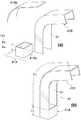
図12に、2ピース構造の外管41が示されている。すなわち、外管41は、上記外管41と同一の材料の鋼管製外管本体41Aおよび合成樹脂製スリット形成体41Bよりなる。 外管本体41Aおよびスリット形成体41Bは、全体として、その長さ方向において、スリット51の無い閉鎖管部Pcおよびスリット51の有る開放管部Poに区画されている。  FIG. 12 shows anouter tube 41 having a two-piece structure. That is, theouter tube 41 includes a steel tubeouter tube body 41A and a synthetic resin slit formedbody 41B made of the same material as theouter tube 41. The outer tubemain body 41A and theslit forming body 41B as a whole are partitioned into a closed tube portion Pc without theslit 51 and an open tube portion Po with theslit 51 in the length direction.

閉鎖管部Pcは、上記外管41の相当部分と実質的に同一構造のものである。開放管部Poは、その半径方向において、外面部材141および内面部材142に分割されている。  The closed tube portion Pc has substantially the same structure as the corresponding portion of theouter tube 41. The open pipe portion Po is divided into anouter surface member 141 and aninner surface member 142 in the radial direction.

図13に詳細に示すように、外面部材141は、横断面コ字状をなすものであって、その占有領域において、上記外管41の外壁41b全体に相当する外面底壁141aと、これの両縁部に隣接して、上記外管41の両側壁41cの一部に相当する一対の外面側壁141bとよりなる。外面部材141の全体が凹状嵌合部143を形成している。  As shown in detail in FIG. 13, theouter surface member 141 has a U-shaped cross section, and in its occupied area, an outersurface bottom wall 141a corresponding to the entireouter wall 41b of theouter tube 41, and Adjacent to both edges, a pair ofouter side walls 141b corresponding to a part of bothside walls 41c of theouter tube 41 is formed. The entireouter surface member 141 forms a concavefitting portion 143.

内面部材142は、横断面コ字状に成形され、同外面底壁141aに内側から重ね合わされた内面底壁142aと、上記外管41の両側壁41cから、外面側壁141bを除いた残りの側壁41cに相当しかつ外面側壁141bと面一となされた一対の内面側壁142bとよりなる。内面底壁142aおよびこれに隣接する内面側壁142bの一部によって、凸状嵌合部144が構成されている。凹状嵌合部143および凸状嵌合部144がはめ合わされた状態で、止ねじ145によって、外面部材141および内面部材142が相互に固定されている。両内面側壁142bの開口は、スリット51を形成している。  Theinner surface member 142 is formed in a U-shaped cross section, and the innersurface bottom wall 142a superimposed on the outersurface bottom wall 141a from the inside, and the remaining side walls excluding the outersurface side wall 141b from bothside walls 41c of theouter tube 41. It is composed of a pair ofinner side wall 142b corresponding to 41c and flush with theouter side wall 141b. A convexfitting portion 144 is constituted by theinner bottom wall 142a and a part of theinner side wall 142b adjacent thereto. In a state where the concavefitting portion 143 and the convexfitting portion 144 are fitted, theouter surface member 141 and theinner surface member 142 are fixed to each other by theset screw 145. Openings in bothinner side walls 142b form slits 51.

図14に示すように、凹状嵌合部143および凸状嵌合部144に相互に係止された抜止め突起146、147が形成されていると、止ねじ145による固定は不要となる。  As shown in FIG. 14, when the retainingprotrusions 146 and 147 locked to the concavefitting portion 143 and the convexfitting portion 144 are formed, the fixing with theset screw 145 becomes unnecessary.

図15は、3ピース構造の外管41を示すものである。この3ピース構造の外管41は、上記2ピース構造の外管41と同様に、外管本体41Aおよびスリット形成体41Bよりなる。  FIG. 15 shows anouter tube 41 having a three-piece structure. Similar to the two-piece structureouter tube 41, the three-piece structureouter tube 41 includes anouter tube body 41A and aslit forming body 41B.

外管本体41Aは、さらに、筒状本体41Aaおよび板状本体41Abに2分割されている。筒状本体41Aaは、長尺角パイプ材を所要長さにカットしたものである。板状本体41Abは、平坦状帯板を屈曲形成したものである。筒状本体41Aaおよび板状本体41Abは、止めねじ151によって相互に固定されている。  The outer tubemain body 41A is further divided into two parts, a cylindrical main body 41Aa and a plate-shaped main body 41Ab. The cylindrical main body 41Aa is obtained by cutting a long rectangular pipe material to a required length. The plate-like main body 41Ab is formed by bending a flat strip. The cylindrical main body 41Aa and the plate-shaped main body 41Ab are fixed to each other by aset screw 151.

外管本体41Aを2分割構造とすることによって、製造コストに低減設計の自由度が図れる。角パイプに代えて、丸パイプを採用しても良く、平坦状帯板を丸棒としてもよい。  By making the outer tubemain body 41A into a two-part structure, it is possible to reduce the manufacturing cost and increase the degree of freedom in design. A round pipe may be employed instead of the square pipe, and the flat strip may be a round bar.

一方、この3ピース構造の外管41を、長さ方向から観察すると、2ピース構造の外管41と同様に、スリット51の無い閉鎖管部Pcおよびスリット51の有る開放管部Poに区画することができる。スリット形成体41Bは、2ピース構造の外管のものに類似する。  On the other hand, when theouter tube 41 having the three-piece structure is observed from the length direction, it is divided into a closed tube portion Pc having noslit 51 and an open tube portion Po having theslit 51, like theouter tube 41 having the two-piece structure. be able to. Theslit forming body 41B is similar to that of a two-piece outer tube.

図16では、4ピース構造の外管41が示されている。この4ピース構造の外管41においても、上記2ピース構造および3ピース構造の外管41と同様に、外管本体41Aおよびスリット形成体41Bよりなる構成が採用されている。さらに、外管41は、閉鎖管部Pcおよび開放管部Poに区画されている。  In FIG. 16, anouter tube 41 having a four-piece structure is shown. In the four-piece structureouter tube 41 as well, the configuration including the outer tubemain body 41A and theslit forming body 41B is adopted in the same manner as the two-piece structure and the three-piece structureouter tube 41. Further, theouter tube 41 is divided into a closed tube portion Pc and an open tube portion Po.

外管本体41Aは、大径パイプ状本体41Aaおよび小径パイプ状本体41Abよりなる。大径パイプ状本体41Aaは、横断面略円形状アルミニウム押出型材よりなる。大径パイプ状本体41Aaの外面の一部には長手方向突条161が設けられている。突条161の先端部には横断面半円形状抜止突起162が設けられている。小径パイプ状本体41Abは、横断面円形状鋼管よりなる。小径パイプ状本体41Abの周壁の一部には長手方向条溝163が形成されている。  The outer tubemain body 41A includes a large-diameter pipe-shaped main body 41Aa and a small-diameter pipe-shaped main body 41Ab. The large-diameter pipe-shaped main body 41Aa is made of an aluminum extrusion mold material having a substantially circular cross section. Alongitudinal ridge 161 is provided on a part of the outer surface of the large-diameter pipe-shaped main body 41Aa. Asemi-circular retaining protrusion 162 having a transverse cross section is provided at the tip of theprotrusion 161. The small-diameter pipe-shaped main body 41Ab is made of a steel pipe having a circular cross section. Alongitudinal groove 163 is formed in a part of the peripheral wall of the small-diameter pipe-shaped main body 41Ab.

大径パイプ状本体41Aaおよび小径パイプ状本体41Abの連結は、双方を長手方向に相対移動させることによって、抜止突起162を小径パイプ状本体41Ab内に収容され、突条161が条溝163に通されることによる。  The large-diameter pipe body 41Aa and the small-diameter pipe body 41Ab are connected by moving both of them in the longitudinal direction so that the retainingprojection 162 is accommodated in the small-diameter pipe body 41Ab, and theprotrusion 161 passes through thegroove 163. By being done.

スリット形成体41Bは、長尺部材41Baおよび短尺部材41Bbよりなる。長尺部材41Baは、横断面略C字状軟質合成樹脂成型品よりなる。長尺部材41Baの頂点には、大径パイプ状本体41Aaの突条161および抜止突起162の横断面と同一横断面をもつ突条164および抜止突起165が設けられている。短尺部材41Bbは、硬質合成樹脂または亜鉛ダイキャスト成型品よりなる。短尺部材41Bbは、長尺部材41Baの横断面と同一の横断面をもつもので、突条166および抜止突起167を有している。  Theslit forming body 41B includes a long member 41Ba and a short member 41Bb. The long member 41Ba is formed of a soft synthetic resin molded product having a substantially C-shaped cross section. At the apex of the long member 41Ba, aprotrusion 164 and a retainingprotrusion 165 having the same cross section as theprotrusion 161 and the retainingprotrusion 162 of the large-diameter pipe-shaped main body 41Aa are provided. The short member 41Bb is made of a hard synthetic resin or a zinc die cast product. The short member 41Bb has the same cross section as that of the long member 41Ba, and includes aprotrusion 166 and a retainingprotrusion 167.

小径パイプ状本体41Abに、長尺部材41Baおよび短尺部材41Bbを連結するための手順は、大径パイプ状本体41Aaおよび小径パイプ状本体41Abを連結する場合に準じる。  The procedure for connecting the long member 41Ba and the short member 41Bb to the small-diameter pipe-shaped main body 41Ab is the same as that for connecting the large-diameter pipe-shaped main body 41Aa and the small-diameter pipe-shaped main body 41Ab.

スリット形成体41Bを、長尺部材41Baおよび短尺部材41Bbに2分割することによる利点は、外管41に対する吐水ヘッド43の取付構造を変更する場合、長尺部材41Baはそのままにしておいて、短尺部材41Bbだけを変更すれば、その変更に対応しうる。  The advantage of splitting theslit forming body 41B into the long member 41Ba and the short member 41Bb is that when the mounting structure of thewater discharge head 43 to theouter tube 41 is changed, the long member 41Ba is left as it is. If only the member 41Bb is changed, the change can be dealt with.

つづいて、吐水ヘッド43のバリエーションを説明する。  Next, variations of thewater discharge head 43 will be described.

図17に示す吐水ヘッド43では、図4に示す吐水ヘッド43の差込ブロック73に代えて、外管41先端部にはめ入れ可能とする横断面方形状差込筒201が設けられている。差込筒201の頂壁から、これに続くヘッド本体72の一部にかけて、略U字状スリット202が形成されている。スリット202によって囲まれた部分には、片持方形状弾性変形部203が形成されている。弾性変形部203の先端部には横断面略三角形状ストッパ204が設けられている。弾性変形部203の基端部には、複数の並列状滑止用突条205が設けられている。  In thewater discharge head 43 shown in FIG. 17, instead of theinsertion block 73 of thewater discharge head 43 shown in FIG. 4, a cross-sectionalsquare insertion tube 201 that can be inserted into the distal end portion of theouter tube 41 is provided. A substantiallyU-shaped slit 202 is formed from the top wall of the plug-incylinder 201 to a part of thehead body 72 following the top wall. In a portion surrounded by theslit 202, a cantilever-shapedelastic deformation portion 203 is formed. Astopper 204 having a substantially triangular cross section is provided at the tip of theelastic deformation portion 203. A plurality of parallelanti-slip ridges 205 are provided at the base end portion of theelastic deformation portion 203.

一方、外管41先端部内面には、図4に示すくぼみ53に代わり、ストッパ204を係合させるための凹所206形成されている。  On the other hand, arecess 206 for engaging thestopper 204 is formed on the inner surface of the distal end portion of theouter tube 41 in place of therecess 53 shown in FIG.

外管41から吐水ヘッド43を取外した状態では、ストッパ204の先端部分は、差込筒201頂面から突出させられている。外管41先端部に差込筒201をはめ入れると、外管41内面によってストッパ204が押下げられ、ストッパ204が凹所206に達すると、ストッパ204の変形が解放されて、ストッパ204が凹所206に係合される。  In a state where thewater discharge head 43 is removed from theouter tube 41, the tip end portion of thestopper 204 is projected from the top surface of theinsertion tube 201. When theinsertion tube 201 is inserted into the tip of theouter tube 41, thestopper 204 is pushed down by the inner surface of theouter tube 41. When thestopper 204 reaches therecess 206, the deformation of thestopper 204 is released and thestopper 204 is recessed. Is engaged at apoint 206.

逆に、外管41から吐水ヘッド43を取外す場合、突条205の部分を押すと、弾性変形部203の先端部分がストッパ204とともに下げられ、ストッパ204および凹所206の係合が解除される。  Conversely, when removing thewater discharge head 43 from theouter tube 41, if the portion of theprotrusion 205 is pushed, the tip portion of theelastic deformation portion 203 is lowered together with thestopper 204, and the engagement between thestopper 204 and therecess 206 is released. .

図18に示す吐水ヘッド43の差込筒211の頂壁には、一対のスリット212が形成されている。両スリット212は、差込筒211の基端から先端にかけて、互いに平行にのびかつ差込筒211先端に開放されている。両スリット212の内側には帯状弾性変形部213が設けられている。弾性変形部213の先端にはストッパ214が設けられている。各スリット212の外側にはこれと平行に一対の逃げ溝215が形成されている。  A pair ofslits 212 are formed on the top wall of theinsertion tube 211 of thewater discharge head 43 shown in FIG. Both slits 212 extend parallel to each other from the proximal end to the distal end of theinsertion tube 211 and open to the distal end of theinsertion tube 211. A belt-likeelastic deformation portion 213 is provided inside bothslits 212. Astopper 214 is provided at the tip of theelastic deformation portion 213. A pair ofescape grooves 215 are formed on the outer side of each slit 212 in parallel therewith.

一方、外筒41先端部の頂壁には開口部221が形成されている。開口部221は、正対視方形状のもので、外筒先端側縁部には係合突起222を有している。開口部221にはストッパ解除用スライドスイッチ223が被覆されている。スライドスイッチ223は、開口部221の周縁部上面に摺接させられた平板状のものである。スライドスイッチ223下面には、開口部221の縦方向縁部を摺動自在に抱きかかえた一対のガイド224が垂下状に設けられている。各ガイド224およびこれと相対する開口部221縁部間には圧縮コイルバネ225が介在させられている。両ガイド224間にはストッパ解除用押動カム226が下方突出状に設けられている。押動カム226は、傾斜状押動面227を有している。  On the other hand, anopening 221 is formed in the top wall of the distal end portion of theouter cylinder 41. Theopening 221 has a shape facing the front, and has anengagement protrusion 222 at the outer cylinder tip side edge. Theopening 221 is covered with a stopperrelease slide switch 223. Theslide switch 223 has a flat plate shape that is brought into sliding contact with the upper surface of the peripheral edge of theopening 221. On the lower surface of theslide switch 223, a pair ofguides 224 that slidably hold the longitudinal edge portion of theopening 221 is provided in a hanging shape. Acompression coil spring 225 is interposed between eachguide 224 and the edge of theopening 221 opposed thereto. A stopper releasingpush cam 226 is provided between theguides 224 so as to protrude downward. Thepush cam 226 has aninclined push face 227.

外管41から吐水ヘッド43を取外した状態では、スライドスイッチ223は、バネ225によって、外管41先端部から遠去かる方向に付勢されている。  In a state where thewater discharge head 43 is removed from theouter tube 41, theslide switch 223 is urged by aspring 225 in a direction away from the distal end portion of theouter tube 41.

外管41先端部に差込筒211をはめ入れると、外管41内面によってストッパ214が押下げられ、ストッパ214が係合突起221を乗り越えると、これに、ストッパ214が係合させられる(図19a)。  When theinsertion tube 211 is fitted into the distal end portion of theouter tube 41, thestopper 214 is pushed down by the inner surface of theouter tube 41. 19a).

外管41から吐水ヘッド43を取外す場合、スライドスイッチ223を、バネ225に抗して、外管41先端部側にスライドさせる。そうすると、押動カム226の押動面227によって、ストッパ214が押下げられ、係合突起221に対するストッパ214の係合が解除される(図19b)。このときに、スライドスイッチ223をスライドさせる場合、ガイド224は逃げ溝215に入り込みことになり、双方の干渉が避けられる。  When removing thewater discharge head 43 from theouter tube 41, theslide switch 223 is slid toward the distal end side of theouter tube 41 against thespring 225. Then, thestopper 214 is pushed down by the pushingsurface 227 of the pushingcam 226, and the engagement of thestopper 214 with the engagingprotrusion 221 is released (FIG. 19b). At this time, when theslide switch 223 is slid, theguide 224 enters theescape groove 215, and interference between the two is avoided.

図20に示す吐水ヘッド43の差込筒231の両側壁内面には一対の磁石232が固定されている。一方、外管41先端部内面には、磁石232を吸引させるための鉄板233が固定されている。  A pair ofmagnets 232 are fixed to the inner surfaces of both side walls of theinsertion tube 231 of thewater discharge head 43 shown in FIG. On the other hand, aniron plate 233 for attracting themagnet 232 is fixed to the inner surface of the distal end portion of theouter tube 41.

最後に、吐水ヘッド43のアタッチメントを説明する。以下に説明するアタッチメントを利用すれば、吐水ヘッド43の取付構造のバリエーションの自由度が増加する。  Finally, the attachment of thewater discharge head 43 will be described. If the attachment described below is used, the degree of freedom of variation in the mounting structure of thewater discharge head 43 increases.

図21に示すアタッチメント241は、合成樹脂によって一体成形されたもので、外管41の先端部内面に合致させられた外面を有しかつ横断面欠円形状差込口242を有している。アタッチメント241の外面には互いに平行にのびた一対の抜止め243が設けられている。外管41の先端部頂壁には、各抜止め243を挿入させた一対の切込み244が形成されている。差込口には丸筒状差込筒(図示しない)が差込み可能である。  Anattachment 241 shown in FIG. 21 is integrally formed of a synthetic resin, has an outer surface matched with the inner surface of the distal end portion of theouter tube 41, and has a cross-sectionally notchedcircular insertion port 242. A pair of retainingmembers 243 extending in parallel with each other are provided on the outer surface of theattachment 241. A pair ofincisions 244 into which the retainingmembers 243 are inserted are formed in the top wall of the distal end portion of theouter tube 41. A round cylindrical insertion tube (not shown) can be inserted into the insertion port.

図22では、別のアタッチメント251が示されている。このアタッチメント251は、その全体が外管41の先端部にはめ入れられかつ止めネジ152によって固定されている。
In FIG. 22, anotherattachment 251 is shown. Theentire attachment 251 is fitted into the distal end portion of theouter tube 41 and is fixed by a set screw 152.

この発明による水栓は、シャワーヘッド等の先端吐水部の位置を任意に変更することを達成するのに適している。  The faucet according to the present invention is suitable for accomplishing arbitrarily changing the position of the tip water discharger such as a shower head.

11 水栓本体
12 吐水パイプ
41 外管
42 内管
43 吐水ヘッド
51 スリット
11 faucet body
12 Water discharge pipe
41 outer pipe
42 Inner pipe
43 Water discharge head
51 Slit

Claims (7)

Translated fromJapanese
水栓本体と、水栓本体から吐水するための吐水パイプとを備えており、吐水パイプは、内外二重構造の外管および内管を有しており、外管の先端部に吐水ヘッドが着脱自在に取付られており、内管の基端部が水栓本体に、その先端部が吐水ヘッドにそれぞれ通水可能に接続されており、外管は、剛性を有しており、内管は、撓性を有しており、外管の周方向の一部に、外管軸方向にのびかつ先端開放スリットが形成されており、外管の先端部から吐水ヘッドを取外した状態で、内管の撓みにともない、スリットを通じて、外管から内管が引出し可能である水栓。  A faucet body and a water discharge pipe for discharging water from the water faucet body. The water discharge pipe has an outer tube and an inner tube of an inner / outer double structure, and a water discharge head is provided at the tip of the outer tube. The inner pipe has a proximal end connected to the faucet body and a distal end connected to the water discharge head so that water can pass through. The outer pipe has rigidity, and the inner pipe Has flexibility, a part extending in the circumferential direction of the outer tube, extending in the direction of the outer tube axis and forming a tip opening slit, with the water discharge head removed from the tip of the outer tube, A faucet that allows the inner tube to be pulled out from the outer tube through the slit as the inner tube bends. 外管の少なくとも一部に、外向き凸状屈曲部が設けられており、スリットは、屈曲部の内面側をのびている請求項1に記載の水栓。  The faucet according to claim 1, wherein an outward convex bent portion is provided in at least a part of the outer tube, and the slit extends on the inner surface side of the bent portion. 外管および内管の基端部は、外管および内管の対応する軸線周りにそれぞれ回転自在に水栓本体に支持されている請求項1または2に記載の水栓。  The faucet according to claim 1 or 2, wherein the proximal end portions of the outer tube and the inner tube are supported by the faucet body so as to be rotatable around corresponding axes of the outer tube and the inner tube, respectively. 外管および内管の先端部と、吐水ヘッドとは、外管および内管の対応する軸線周りにそれぞれ相対回転自在である請求項1〜3のいずれか1つに記載の水栓。  The faucet according to any one of claims 1 to 3, wherein a distal end portion of the outer tube and the inner tube and the water discharge head are relatively rotatable around corresponding axes of the outer tube and the inner tube.スリットにカバーが被覆されており、カバーは、スリット長手方向にのびかつ相対させた縁部を有する一対のカバー半体を備えており、各カバー半体は、撓み性を有しており、各カバー半体の撓みにともない、同両縁部間を、内管が通過可能である請求項1〜4のいずれか1つに記載の水栓。The cover is covered with a slit, and the cover includes a pair of cover halves having edges extending in the slit longitudinal direction and opposed to each other, each cover half having flexibility, The water faucet according to any one of claims 1 to 4, wherein the inner pipe can pass between both edge portions as the cover half body is bent. 外管が、その長さ方向において、スリットの無い閉鎖管部およびスリットの有る開放管部に区画されており、開放管部において、スリットを除いて、内管を取囲む部分が、内管保護用合成樹脂によって形成されている請求項1〜5のいずれか1つに記載の水栓。  The outer tube is partitioned into a closed tube portion without slits and an open tube portion with slits in the length direction, and the portion surrounding the inner tube except for the slits in the open tube portion protects the inner tube. The faucet according to any one of claims 1 to 5, wherein the faucet is formed of a synthetic resin. 外管の先端部に吐水ヘッドが取付られた状態で、外管の先端部に差込解除自在に差込まれかつ内管を通した差込筒部が吐水ヘッドに設けられており、差込筒部の周壁に、差込筒部の差込解除方向の移動を規制するためのストッパが設けられており、ストッパは、差込筒部の外面に対して出入自在であり、外管の先端部内面に、出入するストッパを進退させうる凹所が形成されており、凹所に対するストッパの進退によって、ストッパが作動・解除しうるようになされている請求項1〜6いずれか1つに記載の水栓。  With the water discharge head attached to the distal end of the outer pipe, the water discharge head is provided with a plug cylinder that is inserted into the distal end of the outer pipe so as to be freely releasable and through the inner pipe. A stopper is provided on the peripheral wall of the tube portion to restrict the movement of the plug tube portion in the insertion release direction. The stopper can be moved in and out of the outer surface of the plug tube portion, and the tip of the outer tube. A recess is formed on the inner surface of the part so that the stopper to be moved in and out can be moved back and forth, and the stopper can be operated and released by the movement of the stopper with respect to the recess. Water faucet.
JP2010001025A2009-11-062010-01-06 Water faucetActiveJP5604113B2 (en)

Priority Applications (1)

Application NumberPriority DateFiling DateTitle
JP2010001025AJP5604113B2 (en)2009-11-062010-01-06 Water faucet

Applications Claiming Priority (3)

Application NumberPriority DateFiling DateTitle
JP20092549962009-11-06
JP2010001025AJP5604113B2 (en)2009-11-062010-01-06 Water faucet

Publications (2)

Publication NumberPublication Date
JP2011117261Atrue JP2011117261A (en)2011-06-16
JP5604113B2 JP5604113B2 (en)2014-10-08

Family

ID=44282890

Family Applications (1)

Application NumberTitlePriority DateFiling Date
JP2010001025AActiveJP5604113B2 (en)2009-11-062010-01-06 Water faucet

Country Status (1)

CountryLink
JP (1)JP5604113B2 (en)

Cited By (7)

* Cited by examiner, † Cited by third party
Publication numberPriority datePublication dateAssigneeTitle
CN104863217A (en)*2015-05-052015-08-26宁波鑫力洁金属制品有限公司Lifting type water tap
JP2017141660A (en)*2016-02-052017-08-17株式会社Lixil Faucet and spout head mounted on faucet
JP2018111996A (en)*2017-01-122018-07-19Toto株式会社Faucet device and washstand including the same
JP2018161220A (en)*2017-03-242018-10-18東邦瓦斯株式会社Shoulder warm water device
US11053670B2 (en)2018-08-232021-07-06Spectrum Brands, Inc.Faucet spray head alignment system
US11346088B2 (en)2018-08-232022-05-31Spectrum Brands, Inc.Faucet head alignment system
US12442164B2 (en)2023-11-202025-10-14Assa Abloy Americas Residential Inc.Faucet spray head alignment system

Citations (6)

* Cited by examiner, † Cited by third party
Publication numberPriority datePublication dateAssigneeTitle
JP2000220175A (en)*1999-01-292000-08-08Toto LtdWater plug device
JP2001182112A (en)*1999-12-282001-07-03Kvk Corp Shower stand
JP2005042433A (en)*2003-07-232005-02-17Mym CorpWater discharge pipe and faucet equipped with the same
JP2007523660A (en)*2003-02-062007-08-23ラツィオナル アクチエンゲゼルシャフト Hand-held spray device for hose reel
JP2007262760A (en)*2006-03-282007-10-11Toto LtdFaucet device
JP2008184731A (en)*2007-01-262008-08-14San-Ei Faucet Mfg Co LtdShower hose pulling-out mechanism

Patent Citations (6)

* Cited by examiner, † Cited by third party
Publication numberPriority datePublication dateAssigneeTitle
JP2000220175A (en)*1999-01-292000-08-08Toto LtdWater plug device
JP2001182112A (en)*1999-12-282001-07-03Kvk Corp Shower stand
JP2007523660A (en)*2003-02-062007-08-23ラツィオナル アクチエンゲゼルシャフト Hand-held spray device for hose reel
JP2005042433A (en)*2003-07-232005-02-17Mym CorpWater discharge pipe and faucet equipped with the same
JP2007262760A (en)*2006-03-282007-10-11Toto LtdFaucet device
JP2008184731A (en)*2007-01-262008-08-14San-Ei Faucet Mfg Co LtdShower hose pulling-out mechanism

Cited By (8)

* Cited by examiner, † Cited by third party
Publication numberPriority datePublication dateAssigneeTitle
CN104863217A (en)*2015-05-052015-08-26宁波鑫力洁金属制品有限公司Lifting type water tap
JP2017141660A (en)*2016-02-052017-08-17株式会社Lixil Faucet and spout head mounted on faucet
JP2018111996A (en)*2017-01-122018-07-19Toto株式会社Faucet device and washstand including the same
JP2018161220A (en)*2017-03-242018-10-18東邦瓦斯株式会社Shoulder warm water device
US11053670B2 (en)2018-08-232021-07-06Spectrum Brands, Inc.Faucet spray head alignment system
US11346088B2 (en)2018-08-232022-05-31Spectrum Brands, Inc.Faucet head alignment system
US11859374B2 (en)2018-08-232024-01-02Assa Abloy Americas Residential Inc.Faucet spray head alignment system
US12442164B2 (en)2023-11-202025-10-14Assa Abloy Americas Residential Inc.Faucet spray head alignment system

Also Published As

Publication numberPublication date
JP5604113B2 (en)2014-10-08

Similar Documents

PublicationPublication DateTitle
JP5604113B2 (en) Water faucet
JP5247392B2 (en) Automatic faucet
US20100102014A1 (en)Over arm shower caddy
KR101603046B1 (en)Slide-button shower head
CA3037951A1 (en)Weight assembly for a faucet
KR100683478B1 (en) Holder device for connection of faucet and water hose
TW201506292A (en)One-touch injection pipe connection device with easy component assembly
KR20170054122A (en)Fitting Apparatus for water purifier
JP4831533B2 (en) Faucet device
JP2022551053A (en) cleaning tools
KR200489827Y1 (en)Flexible hose
JPS6320135B2 (en)
JP2012046956A (en)Faucet
JP2002267080A (en)Easy release joint
JP5103200B2 (en) Bath circulator
KR200482672Y1 (en)A connector for connecting shower hose
KR200475865Y1 (en)Connection adapter for gas container
JP4186621B2 (en) Piping connection device and clip
JP2012072561A (en)Faucet and facet construction method
KR200479755Y1 (en)Drain plug
JP5095465B2 (en) Piping structure of joint housing box and hot and cold water mixing faucet
KR200399786Y1 (en)Holder device for connection of a tap and water supply hose
JP4755471B2 (en) Stopper for hose
JP2020070578A (en) Faucet device
KR20170059848A (en)The Storage Box of Shower Hose

Legal Events

DateCodeTitleDescription
A621Written request for application examination

Free format text:JAPANESE INTERMEDIATE CODE: A621

Effective date:20121225

A977Report on retrieval

Free format text:JAPANESE INTERMEDIATE CODE: A971007

Effective date:20140115

A131Notification of reasons for refusal

Free format text:JAPANESE INTERMEDIATE CODE: A131

Effective date:20140121

A521Request for written amendment filed

Free format text:JAPANESE INTERMEDIATE CODE: A523

Effective date:20140319

TRDDDecision of grant or rejection written
A01Written decision to grant a patent or to grant a registration (utility model)

Free format text:JAPANESE INTERMEDIATE CODE: A01

Effective date:20140729

A61First payment of annual fees (during grant procedure)

Free format text:JAPANESE INTERMEDIATE CODE: A61

Effective date:20140825

R150Certificate of patent or registration of utility model

Ref document number:5604113

Country of ref document:JP

Free format text:JAPANESE INTERMEDIATE CODE: R150

R250Receipt of annual fees

Free format text:JAPANESE INTERMEDIATE CODE: R250

R250Receipt of annual fees

Free format text:JAPANESE INTERMEDIATE CODE: R250

R250Receipt of annual fees

Free format text:JAPANESE INTERMEDIATE CODE: R250

R250Receipt of annual fees

Free format text:JAPANESE INTERMEDIATE CODE: R250

R250Receipt of annual fees

Free format text:JAPANESE INTERMEDIATE CODE: R250

R250Receipt of annual fees

Free format text:JAPANESE INTERMEDIATE CODE: R250

R250Receipt of annual fees

Free format text:JAPANESE INTERMEDIATE CODE: R250

R250Receipt of annual fees

Free format text:JAPANESE INTERMEDIATE CODE: R250

R250Receipt of annual fees

Free format text:JAPANESE INTERMEDIATE CODE: R250


[8]ページ先頭

©2009-2025 Movatter.jp